Embed Size (px)
Citation preview
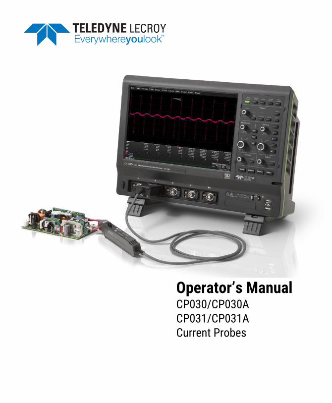
Operator’s Manual CP030/CP030A CP031/CP031A Current Probes

CP03x/CP03xA Current Probes Operator’s Manual
July, 2017
CP030/CP030A and CP031/CP031A Current Probes Operator’s Manual
© 2017 Teledyne LeCroy, Inc. All rights reserved.
Unauthorized duplication of Teledyne LeCroy documentation materials other than for internal sales and distribution purposes is strictly prohibited. However, clients are encouraged to duplicate and distribute Teledyne LeCroy documentation for internal educational purposes.
Teledyne LeCroy is a registered trademark of Teledyne LeCroy, Inc. Windows is a registered trademark of Microsoft Corporation. Other product or brand names are trademarks or requested trademarks of their respective holders. Information in this publication supersedes all earlier versions. Specifications are subject to change without notice.
928616-00 Rev A July, 2017
Operator’s Manual
i
Contents Safety Instructions ..................................................................................................................... 1
Symbols .............................................................................................................................................. 1
Precautions ........................................................................................................................................ 1
Introduction ................................................................................................................................ 3
Specifications ............................................................................................................................. 4
Warranted Characteristics ................................................................................................................ 4
Nominal Characteristics .................................................................................................................... 4
Typical Characteristics ...................................................................................................................... 5
Environmental Characteristics ......................................................................................................... 5
Physical Characteristics ................................................................................................................... 5
Safety Ratings .................................................................................................................................... 6
CP030/CP030A Derating Curve - Maximum Input Current vs. Frequency*................................... 7
CP030/CP030A Insertion Impedance vs. Frequency* .................................................................... 7
CP031/CP031A Derating Curve - Maximum Input Current vs. Frequency .................................... 8
CP031/CP031A Insertion Impedance vs. Frequency ...................................................................... 8
Operation .................................................................................................................................... 9
Precautions ........................................................................................................................................ 9
Connecting to the Test Instrument ................................................................................................10
Connecting to the Test Circuit ........................................................................................................10
Operating with an Oscilloscope ......................................................................................................11
Performance Verification .......................................................................................................... 13
Test Equipment Required ................................................................................................................14
Preliminary Procedure .....................................................................................................................14
Functional Check .............................................................................................................................15
Check LF Accuracy ..........................................................................................................................15
CP03x Test Record ..........................................................................................................................17
CP03x/CP03xA Current Probes
ii
Care and Maintenance .............................................................................................................. 18
Cleaning ............................................................................................................................................18
Calibration Interval ..........................................................................................................................18
Service Strategy ...............................................................................................................................18
Troubleshooting ...............................................................................................................................18
Returning a Product for Service ................................................................................................ 19
Technical Support ..................................................................................................................... 20
Live Support .....................................................................................................................................20
Resources .........................................................................................................................................20
Service Centers ................................................................................................................................20
Warranty ................................................................................................................................... 21
Certifications ............................................................................................................................ 22
EMC Compliance ..............................................................................................................................22
Safety Compliance ...........................................................................................................................23
Environmental Compliance .............................................................................................................24
Operator’s Manual
1
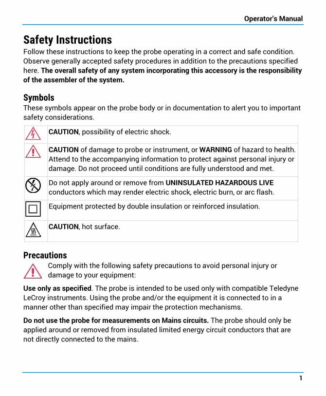
Safety Instructions Follow these instructions to keep the probe operating in a correct and safe condition. Observe generally accepted safety procedures in addition to the precautions specified here. The overall safety of any system incorporating this accessory is the responsibility of the assembler of the system.
Symbols These symbols appear on the probe body or in documentation to alert you to important safety considerations.
CAUTION, possibility of electric shock.
CAUTION of damage to probe or instrument, or WARNING of hazard to health. Attend to the accompanying information to protect against personal injury or damage. Do not proceed until conditions are fully understood and met.
Do not apply around or remove from UNINSULATED HAZARDOUS LIVE conductors which may render electric shock, electric burn, or arc flash.
Equipment protected by double insulation or reinforced insulation.
CAUTION, hot surface.
Precautions Comply with the following safety precautions to avoid personal injury or damage to your equipment:
Use only as specified. The probe is intended to be used only with compatible Teledyne LeCroy instruments. Using the probe and/or the equipment it is connected to in a manner other than specified may impair the protection mechanisms.
Do not use the probe for measurements on Mains circuits. The probe should only be applied around or removed from insulated limited energy circuit conductors that are not directly connected to the mains.
CP03x/CP03xA Current Probes
2
Do not overload; observe all ratings. To avoid electric shock or fire, do not connect the current probe to any wire that carries voltages or currents that exceed the ratings of the probe.
Connect and disconnect properly. Connect the probe to the measurement instrument before connecting to the circuit/conductor being measured. Avoid damaging the cable through excessive bending.
Never install or remove the probe on bare conductors which are energized. The transformer core and shield are grounded but not insulated and may contact the conductor when the locking lever is open.
Be careful not to damage the insulation surface when making measurements. Before clamping to the conductor being measured, check that the insulation on the conductor is undamaged, and take care not to damage the insulation when clamping the conductor. Any damage to the insulation could cause an electric shock.
Use only indoors and within the operational environment listed. Do not use in wet or explosive atmospheres.
Do not remove the probe's casing. Touching exposed connections may result in electric shock.
Keep product surfaces clean and dry.
Comply with the maximum input current vs. frequency derating when measuring current that includes a high frequency component. Using the probe at high frequencies or in strong magnetic fields may cause the device to become abnormally hot, resulting in fire, equipment damage or burns.
Do not operate with suspected failures. Before each use, inspect the probe and accessories for any damage such as tears or other defects in the probe body, cable jacket, accessories, etc. If any part is damaged, cease operation immediately and sequester the probe from inadvertent use.
NOTE: Depending on the amplitude and frequency of the current being measured, the sensor head may emit a resonant sound. This sound may also occur during demagnetizing operation, but it does not represent a malfunction (device failure).
Operator’s Manual
3
Introduction The CP030, CP030A, CP031, and CP031A current probes are designed for easy, highly accurate current measurements. The compact probes offer wide bandwidth with over-current protection. The probes utilize a combination of Hall-effect and transformer technology which enables measurements to be made on DC, AC and impulse currents.
The CP030 and CP030A have a 50 MHz bandwidth and are designed to measure continuous currents up to 30 Amp. The CP030-3M probe has a 10 MHz bandwidth and is designed to measure continuous currents up to 30 Amp.
NOTE: All CP030A probes, regardless of cable length, will indicate default probe bandwidth of 50 MHz in the Attributes section of the Probe dialog.
The CP031 and CP031A have a 100 MHz bandwidth and are designed to measure continuous currents up to 30 Amp.
The CP03x probes are compatible with most Teledyne LeCroy MAUI oscilloscopes with a ProBus interface running Windows XP Professional® or later.
The CP03xA probes are compatible with most Teledyne LeCroy MAUI oscilloscopes with a ProBus interface running X-Stream™ firmware version 7.8.x.x or later.
See the product page at teledynelecroy.com/probes for compatibility, or contact your local service center. Your oscilloscope may be made compatible with the probes with appropriate software upgrades.
With the ProBus interface, the probe becomes an integral part of the measuring instrument. The bandwidth limit, Auto Zero and Degauss functions are all controlled from the instrument’s touch screen user interface. The interface provides power to the probe, so no external power supply is needed.
CP03x/CP03xA Current Probes
4
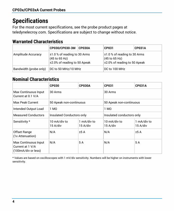
Specifications For the most current specifications, see the probe product pages at teledynelecroy.com. Specifications are subject to change without notice.
Warranted Characteristics CP030/CP030-3M CP030A CP031 CP031A
Amplitude Accuracy ±1.0 % of reading to 30 Arms (45 to 65 Hz) ±2.0% of reading to 50 Apeak
±1.0 % of reading to 30 Arms (45 to 65 Hz) ±2.0% of reading to 50 Apeak
Bandwidth (probe only) DC to 50 MHz/10 MHz DC to 100 MHz
Nominal Characteristics CP030 CP030A CP031 CP031A
Max Continuous Input Current at 0.1 V/A
30 Arms 30 Arms
Max Peak Current 50 Apeak non-continuous 50 Apeak non-continuous
Intended Output Load 1 MΩ 1 MΩ
Measured Conductors Insulated Conductors only Insulated conductors only
Sensitivity * 10 mA/div to 15 A/div
1 mA/div to 15 A/div
10 mA/div to 15 A/div
1 mA/div to 15 A/div
Offset Range (1x Attenuation)
N/A ±5 A N/A ±5 A
Max Continuous Input Current at 1 V/A (100mA/div or less)
N/A 5 A N/A 5 A
* Values are based on oscilloscopes with 1 mV/div sensitivity. Numbers will be higher on instruments with lower sensitivity.
Operator’s Manual
5
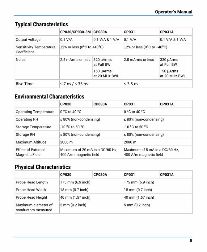
Typical Characteristics CP030/CP030-3M CP030A CP031 CP031A
Output voltage 0.1 V/A 0.1 V/A & 1 V/A 0.1 V/A 0.1 V/A & 1 V/A
Sensitivity Temperature Coefficient
±2% or less (0⁰C to +40⁰C) ±2% or less (0⁰C to +40⁰C)
Noise 2.5 mArms or less 320 µArms at Full BW
150 µArms at 20 MHz BWL
2.5 mArms or less 320 µArms at Full BW
150 µArms at 20 MHz BWL
Rise Time ≤ 7 ns / ≤ 35 ns ≤ 3.5 ns
Environmental Characteristics CP030 CP030A CP031 CP031A
Operating Temperature 0 ⁰C to 40 ⁰C 0 ⁰C to 40 ⁰C
Operating RH ≤ 80% (non-condensing) ≤ 80% (non-condensing)
Storage Temperature -10 ⁰C to 50 ⁰C -10 ⁰C to 50 ⁰C
Storage RH ≤ 80% (non-condensing) ≤ 80% (non-condensing)
Maximum Altitude 2000 m 2000 m
Effect of External Magnetic Field
Maximum of 20 mA in a DC/60 Hz, 400 A/m magnetic field
Maximum of 5 mA in a DC/60 Hz, 400 A/m magnetic field
Physical Characteristics CP030 CP030A CP031 CP031A
Probe Head Length 175 mm (6.9 inch) 175 mm (6.9 inch)
Probe Head Width 18 mm (0.7 inch) 18 mm (0.7 inch)
Probe Head Height 40 mm (1.57 inch) 40 mm (1.57 inch)
Maximum diameter of conductors measured
5 mm (0.2 inch) 5 mm (0.2 inch)
CP03x/CP03xA Current Probes
6
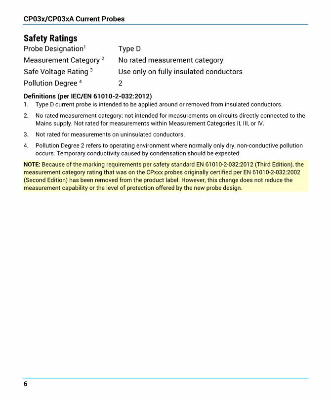
Safety Ratings Probe Designation1 Type D Measurement Category 2 No rated measurement category Safe Voltage Rating 3 Use only on fully insulated conductors Pollution Degree 4 2
Definitions (per IEC/EN 61010-2-032:2012) 1. Type D current probe is intended to be applied around or removed from insulated conductors.
2. No rated measurement category; not intended for measurements on circuits directly connected to the Mains supply. Not rated for measurements within Measurement Categories II, III, or IV.
3. Not rated for measurements on uninsulated conductors.
4. Pollution Degree 2 refers to operating environment where normally only dry, non-conductive pollution occurs. Temporary conductivity caused by condensation should be expected.
NOTE: Because of the marking requirements per safety standard EN 61010-2-032:2012 (Third Edition), the measurement category rating that was on the CPxxx probes originally certified per EN 61010-2-032:2002 (Second Edition) has been removed from the product label. However, this change does not reduce the measurement capability or the level of protection offered by the new probe design.
Operator’s Manual
7
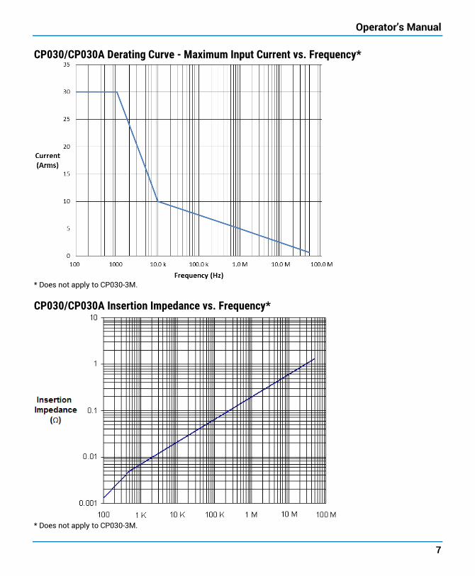
CP030/CP030A Derating Curve - Maximum Input Current vs. Frequency*
* Does not apply to CP030-3M.
CP030/CP030A Insertion Impedance vs. Frequency*
* Does not apply to CP030-3M.
CP03x/CP03xA Current Probes
8
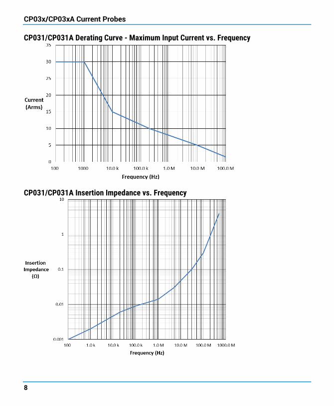
CP031/CP031A Derating Curve - Maximum Input Current vs. Frequency
CP031/CP031A Insertion Impedance vs. Frequency
Operator’s Manual
9
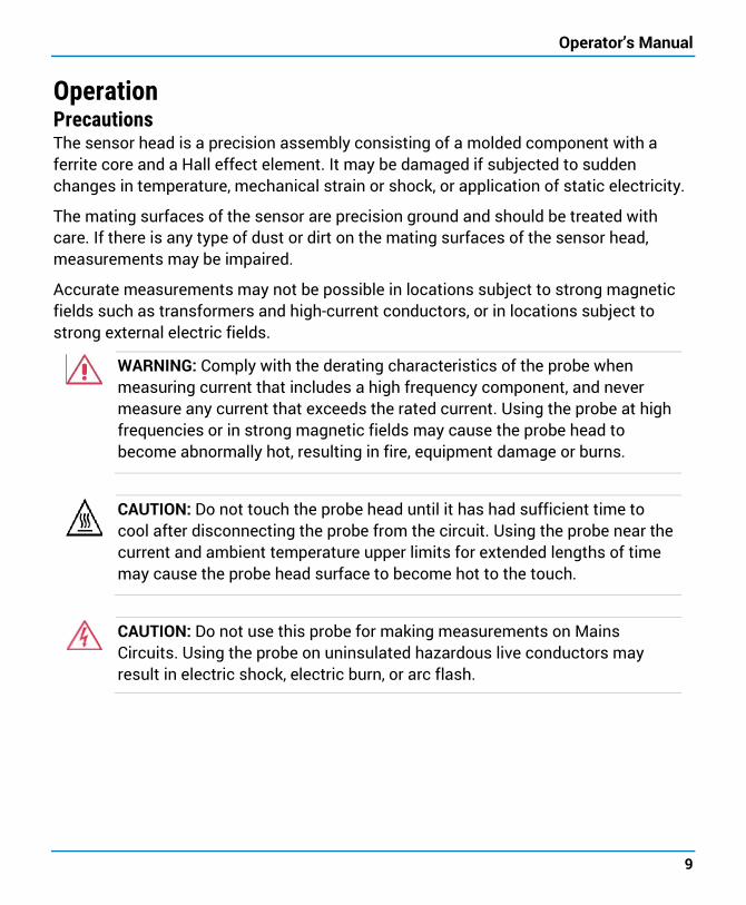
Operation Precautions The sensor head is a precision assembly consisting of a molded component with a ferrite core and a Hall effect element. It may be damaged if subjected to sudden changes in temperature, mechanical strain or shock, or application of static electricity.
The mating surfaces of the sensor are precision ground and should be treated with care. If there is any type of dust or dirt on the mating surfaces of the sensor head, measurements may be impaired.
Accurate measurements may not be possible in locations subject to strong magnetic fields such as transformers and high-current conductors, or in locations subject to strong external electric fields.
WARNING: Comply with the derating characteristics of the probe when measuring current that includes a high frequency component, and never measure any current that exceeds the rated current. Using the probe at high frequencies or in strong magnetic fields may cause the probe head to become abnormally hot, resulting in fire, equipment damage or burns.
CAUTION: Do not touch the probe head until it has had sufficient time to cool after disconnecting the probe from the circuit. Using the probe near the current and ambient temperature upper limits for extended lengths of time may cause the probe head surface to become hot to the touch.
CAUTION: Do not use this probe for making measurements on Mains Circuits. Using the probe on uninsulated hazardous live conductors may result in electric shock, electric burn, or arc flash.
CP03x/CP03xA Current Probes
10
Connecting to the Test Instrument The probe has been designed for use with the Teledyne LeCroy instruments equipped with the ProBus interface. When you attach the probe output connector to the instrument’s input connector, the instrument will:
• Recognize the probe model
• Set the input termination to 1 MΩ
• Activate the probe control functions in the touch screen user interface.
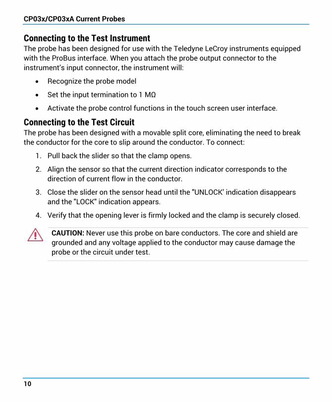
Connecting to the Test Circuit The probe has been designed with a movable split core, eliminating the need to break the conductor for the core to slip around the conductor. To connect:
1. Pull back the slider so that the clamp opens.
2. Align the sensor so that the current direction indicator corresponds to the direction of current flow in the conductor.
3. Close the slider on the sensor head until the "UNLOCK’ indication disappears and the "LOCK" indication appears.
4. Verify that the opening lever is firmly locked and the clamp is securely closed.
CAUTION: Never use this probe on bare conductors. The core and shield are grounded and any voltage applied to the conductor may cause damage the probe or the circuit under test.
Operator’s Manual
11
Operating with an Oscilloscope When connected to a Teledyne LeCroy oscilloscope, the displayed scale factor and measurement values will be adjusted to account for the effective gain of the probe.
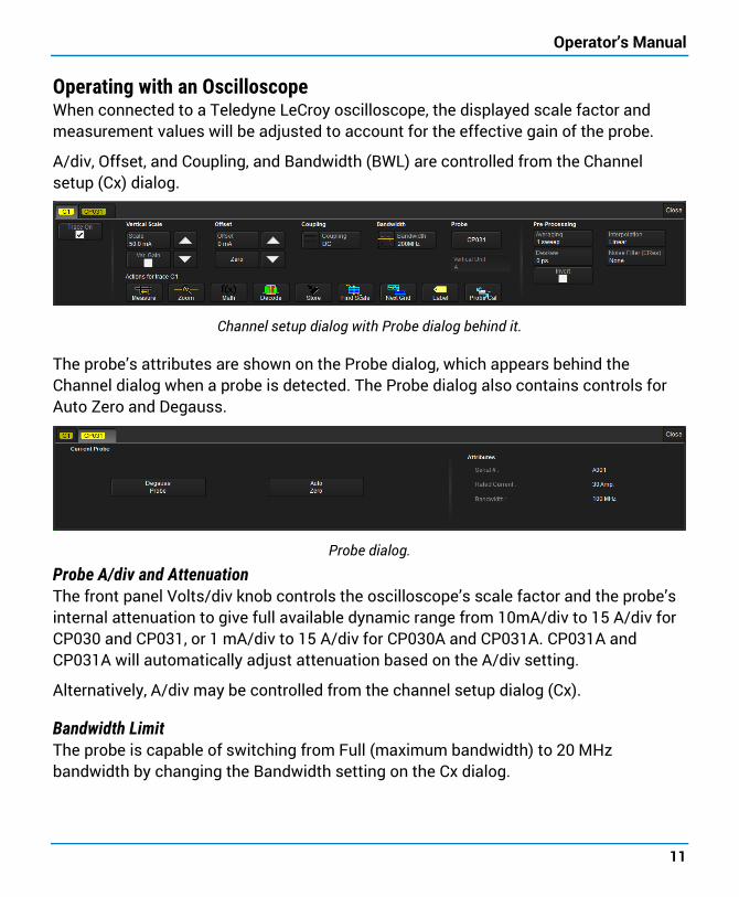
A/div, Offset, and Coupling, and Bandwidth (BWL) are controlled from the Channel setup (Cx) dialog.
Channel setup dialog with Probe dialog behind it.
The probe’s attributes are shown on the Probe dialog, which appears behind the Channel dialog when a probe is detected. The Probe dialog also contains controls for Auto Zero and Degauss.
Probe dialog.
Probe A/div and Attenuation The front panel Volts/div knob controls the oscilloscope’s scale factor and the probe’s internal attenuation to give full available dynamic range from 10mA/div to 15 A/div for CP030 and CP031, or 1 mA/div to 15 A/div for CP030A and CP031A. CP031A and CP031A will automatically adjust attenuation based on the A/div setting.
Alternatively, A/div may be controlled from the channel setup dialog (Cx).
Bandwidth Limit The probe is capable of switching from Full (maximum bandwidth) to 20 MHz bandwidth by changing the Bandwidth setting on the Cx dialog.
CP03x/CP03xA Current Probes
12
AC Coupling In general, using offset to adjust a DC current on the screen is the preferred method to measure transient signals in the presence of a larger DC currents. The offset has limits that will cause a signal that is beyond the linear operating range of the probe to go off the screen, preventing measurement errors.
There are times, however, when it is convenient to use AC coupling to remove the DC component of the measured signal from the measurement. Selecting AC uses the scope AC coupling at the probe output to remove any steady state value from the displayed voltage.
NOTE: Since this AC coupling is on the probe output, DC current beyond the linear range of the probe will cause the probe to saturate and make the displayed waveform inaccurate. It is important not to exceed the maximum linear input values when using AC coupling. The maximum DC input current is 30A when the probe is in 0.1 V/A sensitivity (>100mA/div), and 5A when the probe is in 1 V/A (≤100mA/div).
Auto Zero The Probe dialog incorporates an Auto Zero function to remove the DC offset from the current probe. Auto Zero must be invoked by the user. After several minutes of warm-up, or when the probe is exposed to a large shift in ambient temperature, some DC offset drift may occur. Open the Probe dialog and touch AUTO ZERO.
Degauss If the probe has been magnetized by external magnetic field or by excessive input, the core can be demagnetized by degaussing. The demagnetizing process takes about 5 seconds and should always be performed before taking a measurement.
Without clamping the probe around a conductor, slide the opening lever to close and lock the probe. Open the Probe dialog and touch DEGAUSS.
An Auto Zero is automatically performed as part of the degauss cycle.
Operator’s Manual
13
Performance Verification This procedure can be used to verify the warranted characteristics of the probe. The recommended calibration interval for the models CP030, CP030-3M, CP030A, CP031, and CP031A Current Probes is one year. The complete performance verification procedure should be performed as the first step of annual calibration. Performance verification can be completed without removing the probe covers or exposing the user to hazardous voltages. Test results can be recorded on a photocopy of the Test Record provided at the end of the manual.
The warranted characteristics of the probe are valid at any temperature within the Environmental Characteristics listed in the Specifications. However, some of the other test equipment used to verify the performance may have environmental limitations required to meet the accuracy needed for the procedure. Make sure that the ambient conditions meet the requirements of all the test instruments used in his procedure.
NOTE: Operation of the probe as described requires software version 4.3.0.0 or higher for CP03x and 7.8.x.x or higher for CP03xA. To confirm the version installed, choose Utilities > Utilities Setup from the oscilloscope menu bar, then open the Status tab.
CP03x/CP03xA Current Probes
14
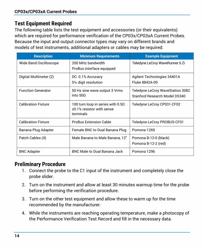
Test Equipment Required The following table lists the test equipment and accessories (or their equivalents) which are required for performance verification of the CP03x/CP03xA Current Probes. Because the input and output connector types may vary on different brands and models of test instruments, additional adapters or cables may be required.
Description Minimum Requirements Example Equipment
Wide Band Oscilloscope 200 MHz bandwidth ProBus interface equipped
Teledyne LeCroy WaveRunner 6 Zi
Digital Multimeter (2) DC: 0.1% Accuracy 5½ digit resolution
Agilent Technologies 34401A Fluke 8842A-09
Function Generator 50 Hz sine wave output 3 Vrms into 50Ω
Teledyne LeCroy WaveStation 3082 Stanford Research Model DS340
Calibration Fixture 100 turn loop in series with 0.5Ω ±0.1% resistor with sense terminals
Teledyne LeCroy CP031-CF02
Calibration Fixture ProBus Extension Cable Teledyne LeCroy PROBUS-CF01
Banana Plug Adapter Female BNC to Dual Banana Plug Pomona 1269
Patch Cables (4) Male Banana to Male Banana, 12" Pomona B-12-0 (black) Pomona B-12-2 (red)
BNC Adapter BNC Male to Dual Banana Jack Pomona 1296
Preliminary Procedure 1. Connect the probe to the C1 input of the instrument and completely close the
probe slider.
2. Turn on the instrument and allow at least 30 minutes warmup time for the probe before performing the verification procedure.
3. Turn on the other test equipment and allow these to warm up for the time recommended by the manufacturer.
4. While the instruments are reaching operating temperature, make a photocopy of the Performance Verification Test Record and fill in the necessary data.
Operator’s Manual
15
Functional Check The functional check will verify the basic operation of the probe functions. It is recommended to perform the functional check prior to the performance verification procedure.
1. Open the C1 setup dialog and confirm that the bandwidth is set to Full (BWL OFF).
2. Verify that the probe is sensed and the probe dialog (CP03x or CP03xA tab) appears behind the C1 setup dialog.
3. Open the probe dialog and degauss the probe by touching DEGAUSS, then OK.
4. Confirm that the message "Performing Degauss on CP03x...." is displayed in the message bar and that no error messages are displayed.
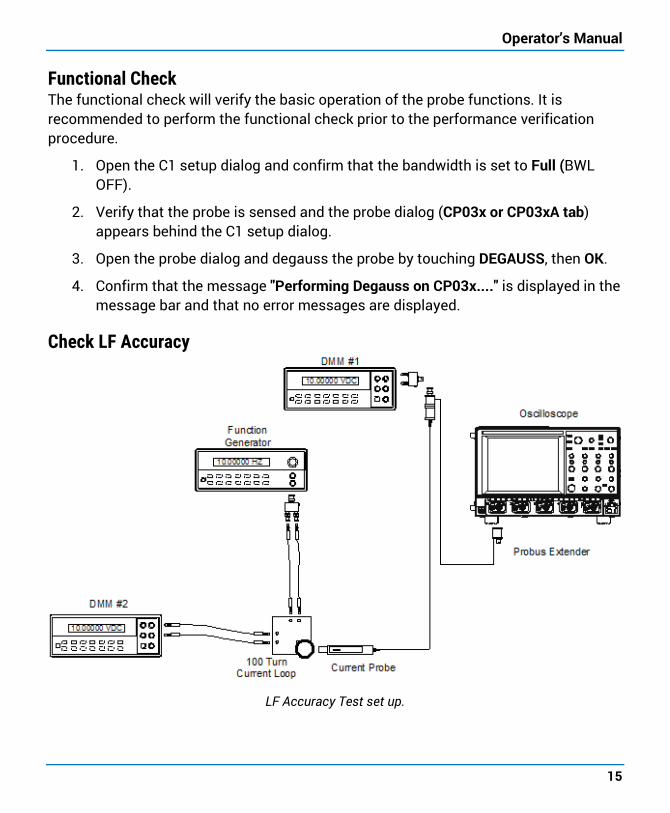
Check LF Accuracy
LF Accuracy Test set up.
CP03x/CP03xA Current Probes
16
1. Set the Function generator to 50 Hz sine wave, output voltage at 3 Vrms with 50Ω output.
2. Remove the probe from the instrument and reconnect using the ProBus extension cable. Connect the BNC male connector of the ProBus extension to DMM #1 using a BNC Female to Dual Banana adapter.
3. Using Banana Patch cords and the BNC to Dual Banana Plug adapter, connect the ’V Source’ and ’V Return’ terminals of the 100 Turn Calibration Loop to the output of the Function Generator.
4. Connect the Current Sense terminals of the 100 Turn Calibration Loop to the voltage inputs of DMM #2.
5. Set both DMMs to measure AC Volt.
6. With the probe removed from any signal and the slider returned to the LOCKED position, degauss the probe by pressing the DEGAUSS button.
7. Set the current probe channel sensitivity to 1 A/div.
8. Open the probe slider and position the probe input around the 100 Turn loop. Close and LOCK the slider.
9. Adjust the Function generator voltage until the voltage measured at the ’Current Sense’ terminals (DMM #2) reads 50 mV ±0.05 mV. (This corresponds to 10 A at the probe head).
10. Record the voltage measured by DMM #1 on the Test Record.
11. Verify that the measured voltage is between 0.989 volt and 1.011 volt.
Operator’s Manual
17
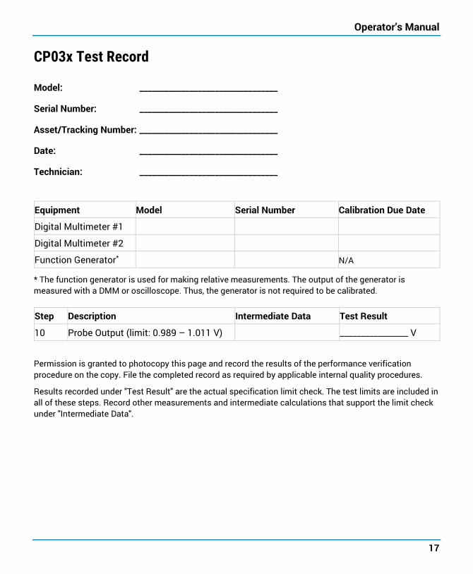
CP03x Test Record
Model: _________________________________
Serial Number: _________________________________
Asset/Tracking Number: _________________________________
Date: _________________________________
Technician: _________________________________
Equipment Model Serial Number Calibration Due Date
Digital Multimeter #1
Digital Multimeter #2
Function Generator* N/A
* The function generator is used for making relative measurements. The output of the generator is measured with a DMM or oscilloscope. Thus, the generator is not required to be calibrated.
Step Description Intermediate Data Test Result
10 Probe Output (limit: 0.989 – 1.011 V) ________________ V
Permission is granted to photocopy this page and record the results of the performance verification procedure on the copy. File the completed record as required by applicable internal quality procedures.
Results recorded under "Test Result" are the actual specification limit check. The test limits are included in all of these steps. Record other measurements and intermediate calculations that support the limit check under "Intermediate Data".
CP03x/CP03xA Current Probes
18
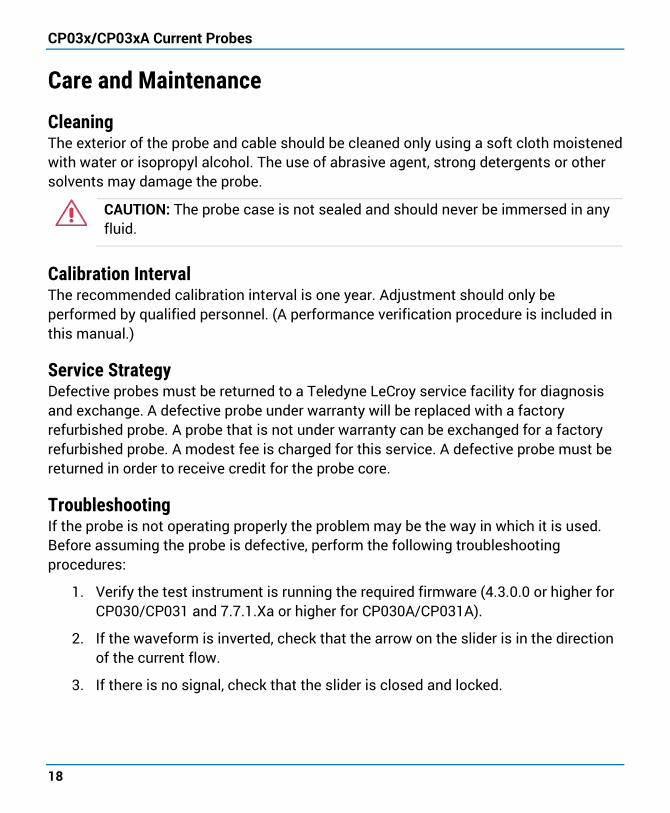
Care and Maintenance
Cleaning The exterior of the probe and cable should be cleaned only using a soft cloth moistened with water or isopropyl alcohol. The use of abrasive agent, strong detergents or other solvents may damage the probe.
CAUTION: The probe case is not sealed and should never be immersed in any fluid.
Calibration Interval The recommended calibration interval is one year. Adjustment should only be performed by qualified personnel. (A performance verification procedure is included in this manual.)
Service Strategy Defective probes must be returned to a Teledyne LeCroy service facility for diagnosis and exchange. A defective probe under warranty will be replaced with a factory refurbished probe. A probe that is not under warranty can be exchanged for a factory refurbished probe. A modest fee is charged for this service. A defective probe must be returned in order to receive credit for the probe core.
Troubleshooting If the probe is not operating properly the problem may be the way in which it is used. Before assuming the probe is defective, perform the following troubleshooting procedures:
1. Verify the test instrument is running the required firmware (4.3.0.0 or higher for CP030/CP031 and 7.7.1.Xa or higher for CP030A/CP031A).
2. If the waveform is inverted, check that the arrow on the slider is in the direction of the current flow.
3. If there is no signal, check that the slider is closed and locked.
Operator’s Manual
19
Returning a Product for Service Contact your regional Teledyne LeCroy service center for calibration or other service. If the product cannot be serviced on location, the service center will give you a Return Material Authorization (RMA) code and instruct you where to ship the product. All products returned to the factory must have an RMA. Return shipments must be prepaid.
Teledyne LeCroy cannot accept COD or Collect shipments. We recommend air-freighting. Insure the item you’re returning for at least the replacement cost.
1. Remove all accessories from the probe. Do not include the manual.
2. Pack the probe in its case, surrounded by the original packing material (or equivalent).
3. Label the case with a tag containing: • The RMA • Name and address of the owner • Probe model and serial number • Description of failure or requisite service
4. Package the probe case in a cardboard shipping box with adequate padding to avoid damage in transit.
5. Mark the outside of the box with the shipping address given to you by Teledyne LeCroy; be sure to add the following:
• ATTN: <RMA code assigned by the Teledyne LeCroy> • FRAGILE
6. Insure the item for the replacement cost of the probe.
7. If returning a probe to a different country: • Mark the shipment as a “Return of US manufactured goods for warranty
repair/recalibration.”
• If there is a cost for the service, list the cost in the value column and the original purchase price “For insurance purposes only.”
• Be very specific as to the reason for shipment. Duties may have to be paid on the value of the service.

CP03x/CP03xA Current Probes
20
Technical Support
Live Support Registered users can contact their local Teledyne LeCroy service center at the number listed on our website. You can also request Technical Support via the website at:
teledynelecroy.com/support/techhelp
Resources Teledyne LeCroy publishes a free Technical Library on its website. Manuals, tutorials, application notes, white papers, and videos are available to help you get the most out of your Teledyne LeCroy products. Visit:
teledynelecroy.com/support/techlib
Service Centers For a complete list of offices by country, including our sales and distribution partners, visit:
teledynelecroy.com/support/contact
Teledyne LeCroy 700 Chestnut Ridge Road Chestnut Ridge, NY, 10977, USA
Sales and Service: Ph: 800-553-2769 / 845-425-2000 FAX: 845-578-5985 [email protected]
Support: Ph: 800-553-2769 [email protected]
Operator’s Manual
21
Warranty Teledyne LeCroy warrants this oscilloscope accessory for normal use and operation within specification for a period of one year from the date of shipment. Spare parts, replacement parts and repairs are warranted for 90 days.
In exercising its warranty, Teledyne LeCroy, at its option, will either repair or replace any assembly returned within its warranty period to the Customer Service Department or an authorized service center. However, this will be done only if the product is determined by Teledyne LeCroy’s examination to be defective due to workmanship or materials, and the defect is not caused by misuse, neglect, accident, abnormal conditions of operation, or damage resulting from attempted repair or modifications by a non-authorized service facility.
The customer will be responsible for the transportation and insurance charges for the return of products to the service facility. Teledyne LeCroy will return all products under warranty with transportation charges prepaid.
This warranty replaces all other warranties, expressed or implied, including but not limited to any implied warranty of merchantability, fitness or adequacy for any particular purposes or use. Teledyne LeCroy shall not be liable for any special, incidental, or consequential damages, whether in contract or otherwise.
CP03x/CP03xA Current Probes
22
Certifications Teledyne LeCroy certifies compliance to the following standards as of the date of publication. As standards evolve, these may no longer be current. Please see the Declaration of Conformity certificate shipped with your product.
EMC Compliance EC Declaration of Conformity - EMC The CP030, CP030A, CP031, and CP031A probes meet the intent of EC Directive 2014/30/EU for Electromagnetic Compatibility. Compliance was demonstrated to the following specifications as listed in the Official Journal of the European Communities:
EN 61326-1:2013 EMC requirements for electrical equipment for measurement, control, and laboratory use. 1
ELECTROMAGNETIC EMISSIONS: EN 55011/A1:2010 Radiated and Conducted Emissions Group 1 Class A 2 3
ELECTROMAGNETIC IMMUNITY: EN 61000-4-2:2009 Electrostatic Discharge, 4 kV contact, 8 kV air, 4 kV vertical/horizontal coupling planes 4
EN 61000-4-3/A2:2010 RF Radiated Electromagnetic Field, 3 V/m, 80-1000 MHz; 3 V/m, 1400 MHz - 2 GHz; 1 V/m, 2 GHz - 2.7 GHz
EN 61000-4-8:2010 Power Frequency Magnetic Field, 3 A/m, 50 Hz; 3 A/m, 60 Hz 1 To ensure compliance with the applicable EMC standards, use high quality shielded interface cables.
2 This product is intended for use in nonresidential areas only. Use in residential areas may cause electromagnetic interference.
3 Emissions which exceed the levels required by this standard may occur when the probe is connected to a test object.
4 Meets Performance Criteria “B” limits of the respective standard: during the disturbance, product undergoes a temporary degradation or loss of function or performance which is self-recoverable.
Operator’s Manual
23
EUROPEAN CONTACT:* Teledyne LeCroy Europe GmbH Im Breitspiel 11c D-69126 Heidelberg Germany Tel: (49) 6221 82700
Australia & New Zealand Declaration of Conformity - EMC The probe complies with the EMC provision of the Radio Communications Act per the following standards, in accordance with requirements imposed by the Australian Communication and Media Authority (ACMA):
AS/NZS CISPR 11:2009/A1:2010, EN 55011:2009/A1:2010 Radiated and Conducted Emissions, Group 1, Class A.
AUSTRALIA / NEW ZEALAND CONTACTS:* RS Components Pty Ltd. Suite 326 The Parade West Kent Town, South Australia 5067
RS Components Ltd. Unit 30 & 31 Warehouse World 761 Great South Road Penrose, Auckland, New Zealand
* Visit teledynelecroy.com/support/contact for the latest contact information.
Safety Compliance EC Declaration of Conformity – Low Voltage The probe meets the intent of EC Directive 2014/35/EU for Product Safety. Compliance was demonstrated to the following specifications as listed in the Official Journal of the European Communities:
IEC/EN 61010-1:2010 Safety requirements for electrical equipment for measurement, control, and laboratory use – Part 1: General requirements
IEC/EN 61010-2-032:2012 Safety Requirements for Electrical Equipment for Measurement, Control, and Laboratory Use – Part 2-032: Particular Requirements for Hand-Held and Hand Manipulated Current Sensors for Electrical Test and Measurement.
CP03x/CP03xA Current Probes
24
Environmental Compliance End-Of-Life Handling
The probe is marked with this symbol to indicate that it complies with the applicable European Union requirements to Directives 2002/96/EC and 2006/66/EC on Waste Electrical and Electronic Equipment (WEEE) and Batteries.
The probe is subject to disposal and recycling regulations that vary by country and region. Many countries prohibit the disposal of waste electronic
equipment in standard waste receptacles. For more information about proper disposal and recycling of your Teledyne LeCroy product, visit teledynelecroy.com/recycle.
Restriction of Hazardous Substances (RoHS) The product and its accessories conform to the 2011/65/EU RoHS2 Directive.


928616-00 Rev A July, 2017