Embed Size (px)
Citation preview
1
CPSC 310 – Software Engineering
Design: UML Review
Short review assuming background from CPSC 210
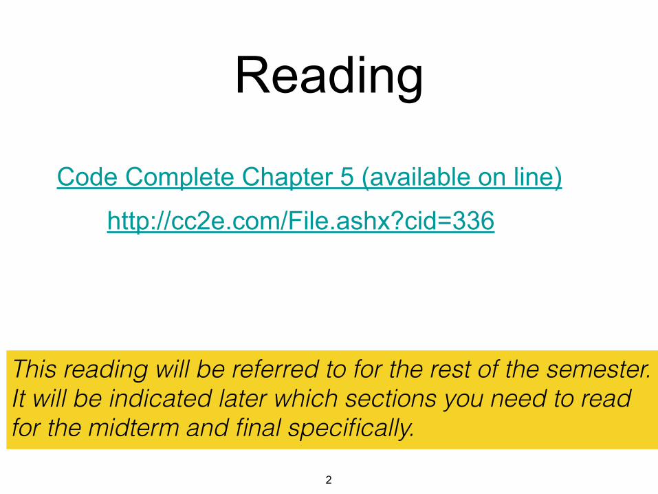
Reading
Code Complete Chapter 5 (available on line)
http://cc2e.com/File.ashx?cid=336
2
This reading will be referred to for the rest of the semester. It will be indicated later which sections you need to read for the midterm and final specifically.
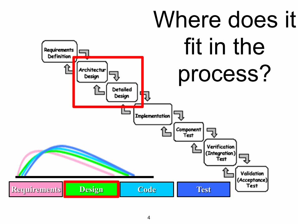
4
Requirements Design Code Test
Where does it fit in the process?
5
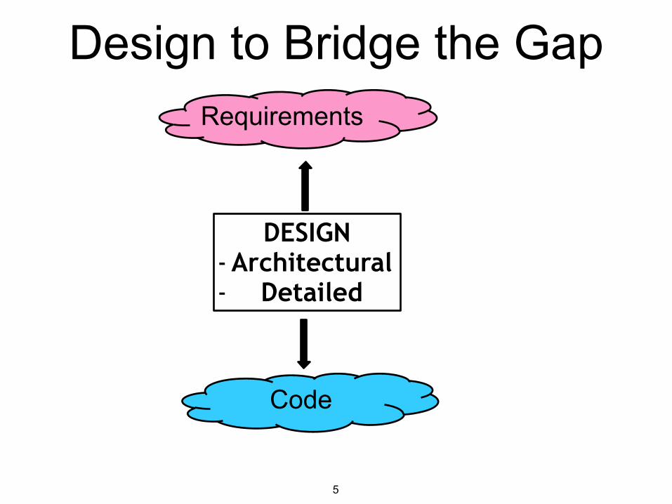
Requirements
Code
DESIGN -Architectural - Detailed
Design to Bridge the Gap
6
■ Facilitates communication ■ Eases system understanding ■ Eases implementation ■ Helps discover problems early ■ Increases product quality ■ Reduces maintenance costs ■ Facilitates product upgrade
Why Design?
7
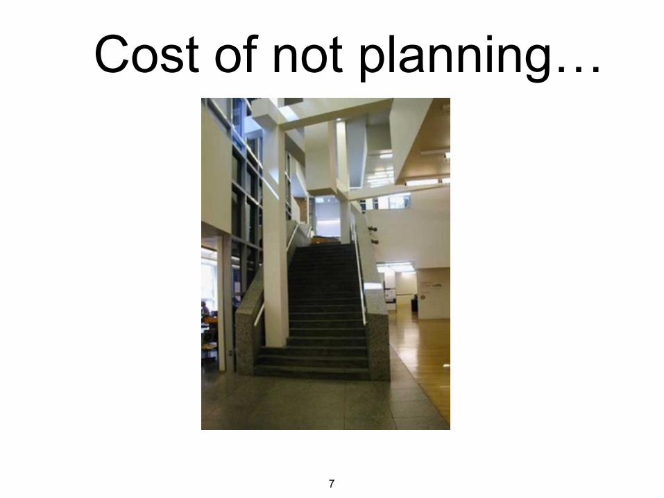
Cost of not planning…
8
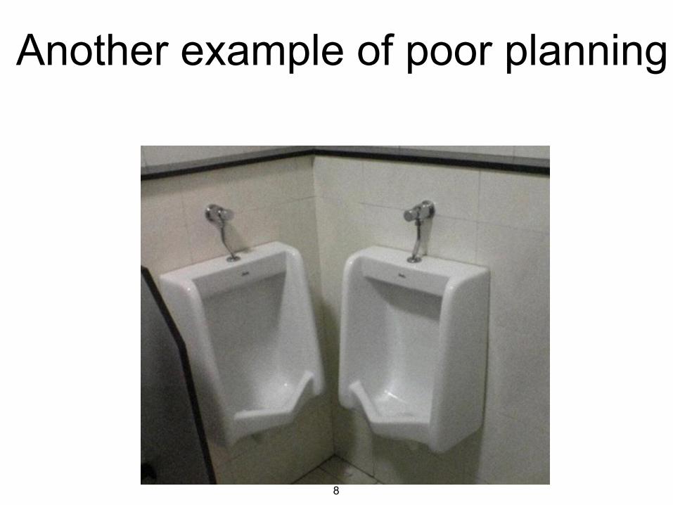
Another example of poor planning
9
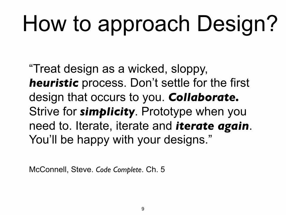
“Treat design as a wicked, sloppy, heuristic process. Don’t settle for the first design that occurs to you. Collaborate. Strive for simplicity. Prototype when you need to. Iterate, iterate and iterate again. You’ll be happy with your designs.” !McConnell, Steve. Code Complete. Ch. 5
How to approach Design?
10
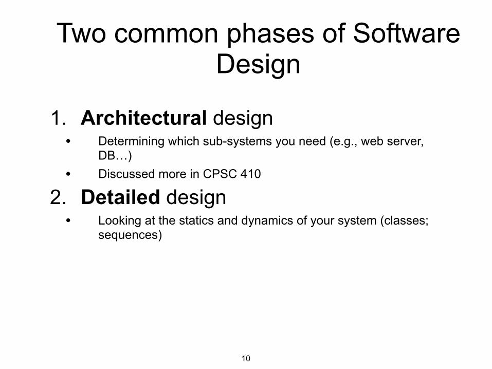
1. Architectural design • Determining which sub-systems you need (e.g., web server,
DB…) • Discussed more in CPSC 410
2. Detailed design • Looking at the statics and dynamics of your system (classes;
sequences)
Two common phases of Software Design
11
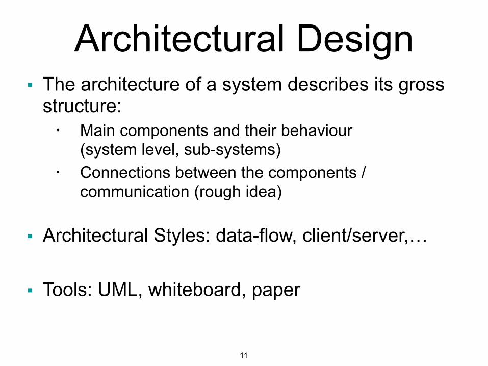
■ The architecture of a system describes its gross structure: • Main components and their behaviour
(system level, sub-systems)
• Connections between the components / communication (rough idea)
!■ Architectural Styles: data-flow, client/server,… !
■ Tools: UML, whiteboard, paper
Architectural Design
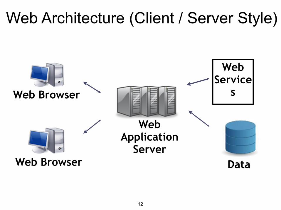
12
Web Browser
Web Application
ServerDataWeb Browser
Web Service
s
Web Architecture (Client / Server Style)
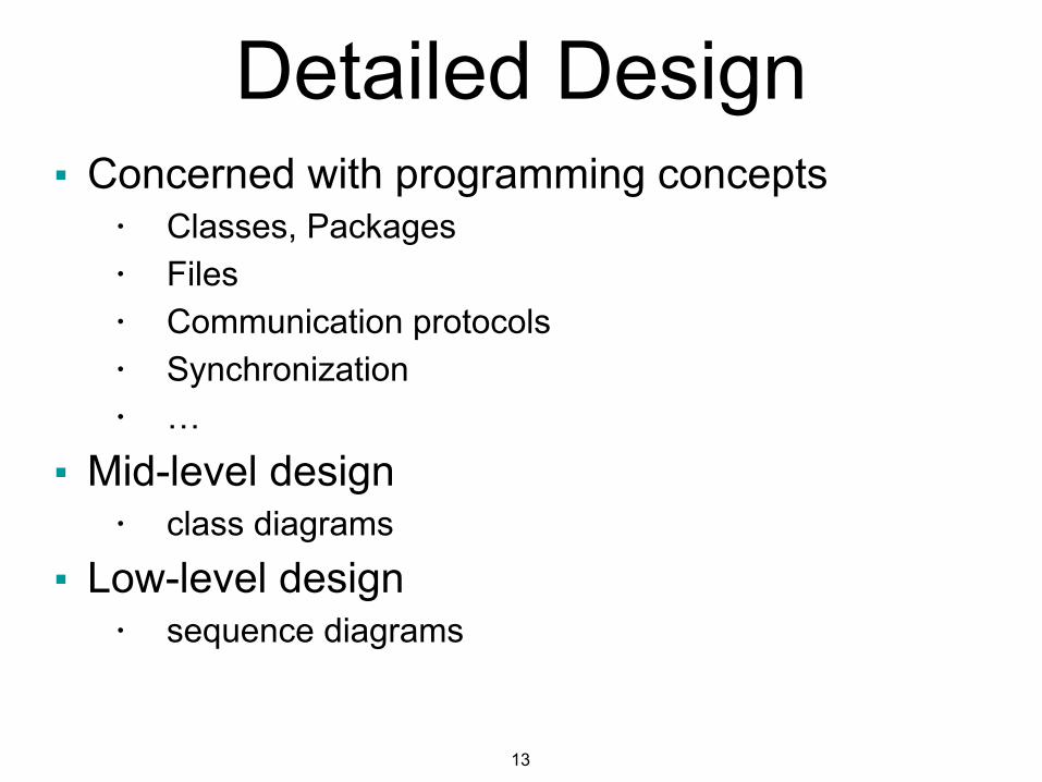
13
■ Concerned with programming concepts • Classes, Packages
• Files
• Communication protocols
• Synchronization
• …
■ Mid-level design • class diagrams
■ Low-level design • sequence diagrams
Detailed Design
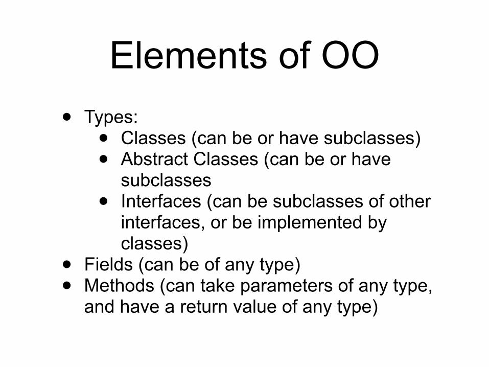
Elements of OO• Types: • Classes (can be or have subclasses) • Abstract Classes (can be or have
subclasses • Interfaces (can be subclasses of other
interfaces, or be implemented by classes)
• Fields (can be of any type) • Methods (can take parameters of any type,
and have a return value of any type)
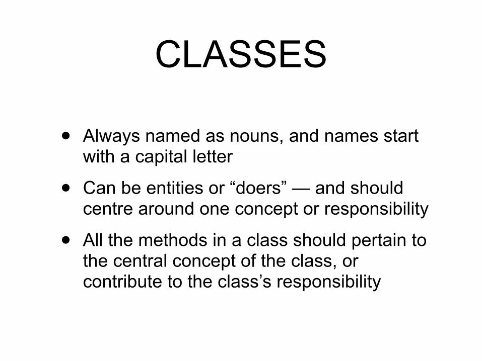
CLASSES
• Always named as nouns, and names start with a capital letter
• Can be entities or “doers” — and should centre around one concept or responsibility
• All the methods in a class should pertain to the central concept of the class, or contribute to the class’s responsibility
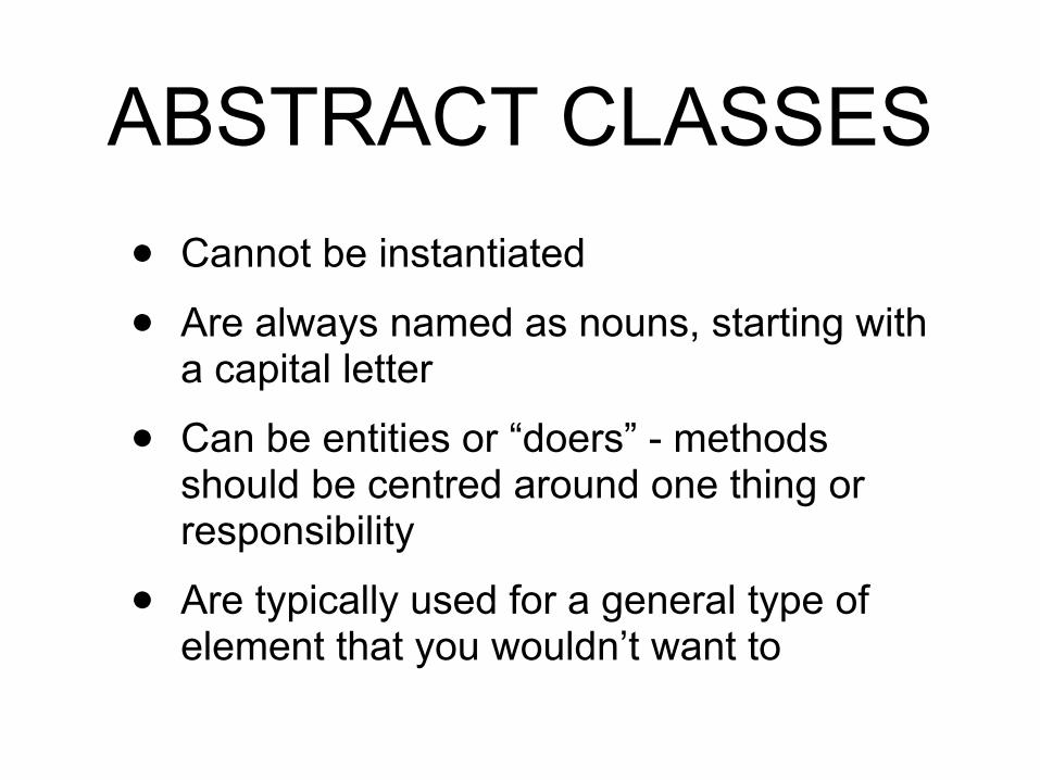
ABSTRACT CLASSES• Cannot be instantiated
• Are always named as nouns, starting with a capital letter
• Can be entities or “doers” - methods should be centred around one thing or responsibility
• Are typically used for a general type of element that you wouldn’t want to
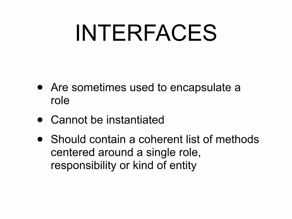
INTERFACES
• Are sometimes used to encapsulate a role
• Cannot be instantiated
• Should contain a coherent list of methods centered around a single role, responsibility or kind of entity
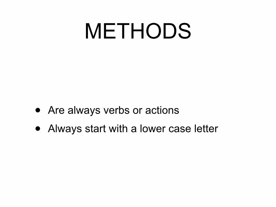
METHODS
• Are always verbs or actions
• Always start with a lower case letter
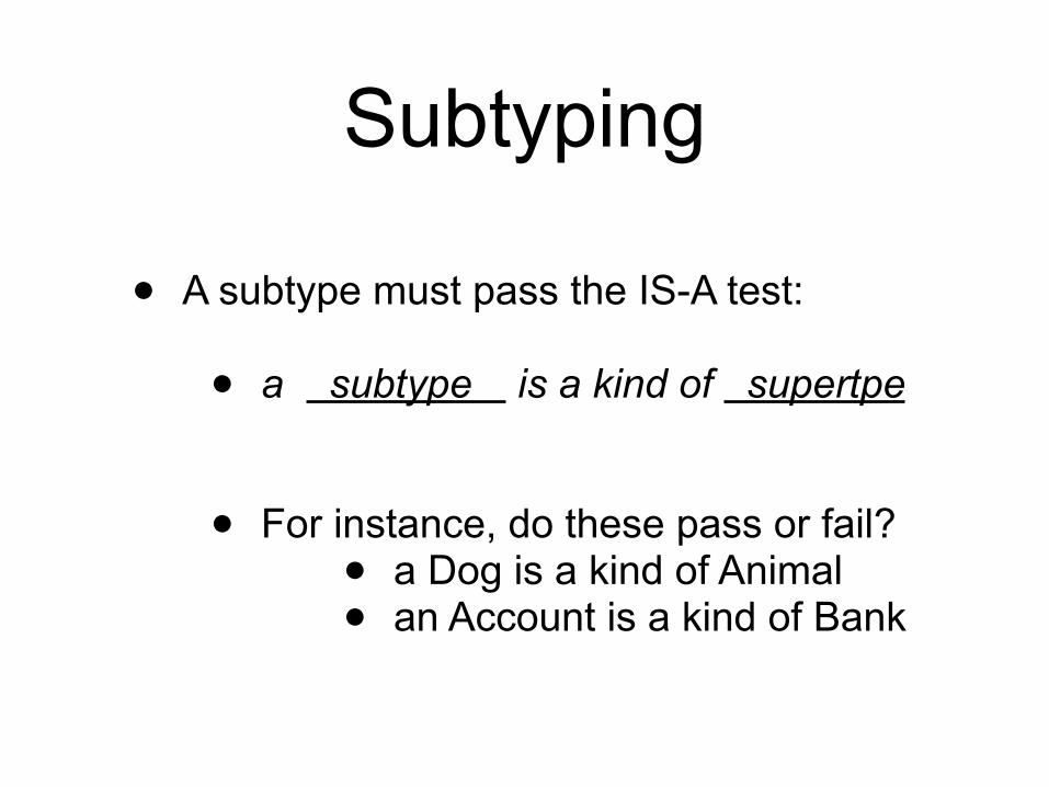
Subtyping
• A subtype must pass the IS-A test: !• a subtype is a kind of supertpe
!!• For instance, do these pass or fail? • a Dog is a kind of Animal • an Account is a kind of Bank
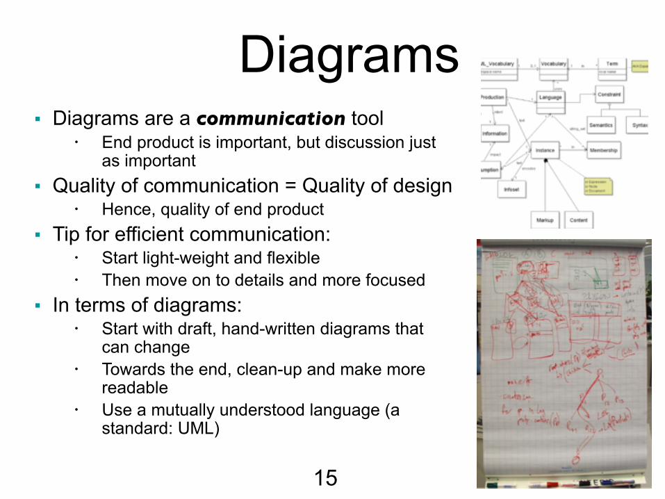
■ Diagrams are a communication tool • End product is important, but discussion just
as important ■ Quality of communication = Quality of design
• Hence, quality of end product ■ Tip for efficient communication:
• Start light-weight and flexible • Then move on to details and more focused
■ In terms of diagrams: • Start with draft, hand-written diagrams that
can change • Towards the end, clean-up and make more
readable • Use a mutually understood language (a
standard: UML)
Diagrams
15
16
!■Used to describe the relationships between classes (and/or packages) in the system !■UML: Unified Modeling Language (not only class diagrams)
!■Main elements of UML class diagrams
• Classes • Relationships
• Generalization (Subtyping) • Association • Aggregation
Class Diagrams
17
!!!!
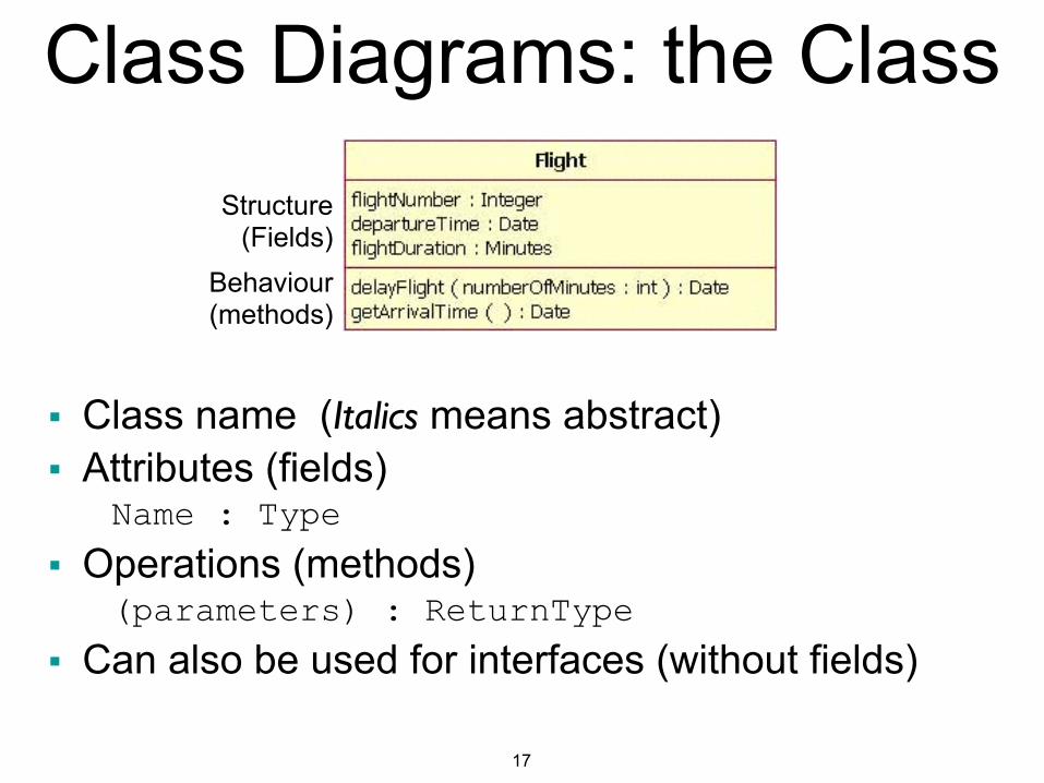
■ Class name (Italics means abstract) ■ Attributes (fields)
Name : Type ■ Operations (methods)
(parameters) : ReturnType ■ Can also be used for interfaces (without fields)
Class Diagrams: the ClassStructure
(Fields)Behaviour (methods)
17
!!!!
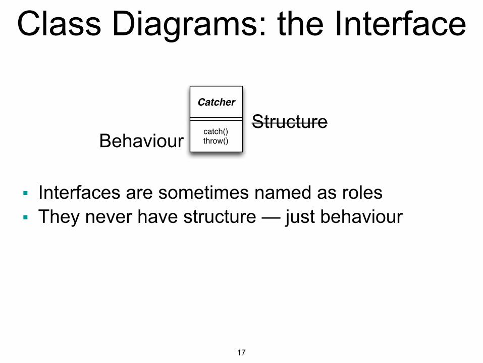
■ Interfaces are sometimes named as roles ■ They never have structure — just behaviour
Class Diagrams: the Interface
StructureBehaviour
Catcher
catch()throw()

18
!!!!!!
Used for: • Inheritance • Interface implementation
Class Diagrams: GeneralizationAre you doing it correctly? Remember:
Use the Is-A test,
19
!!!!!
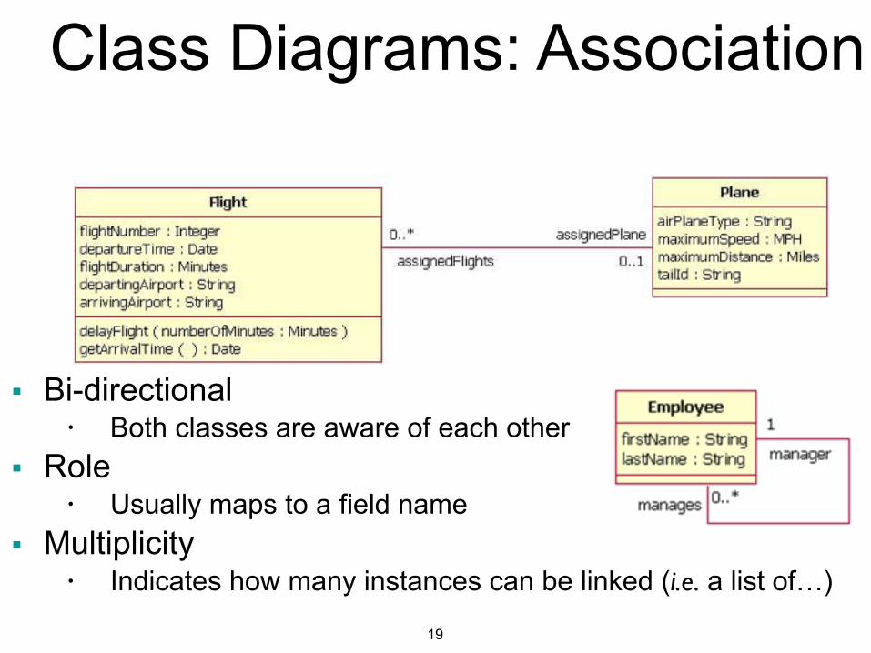
■ Bi-directional • Both classes are aware of each other
■ Role • Usually maps to a field name
■ Multiplicity • Indicates how many instances can be linked (i.e. a list of…)
Class Diagrams: Association
20
!!!!
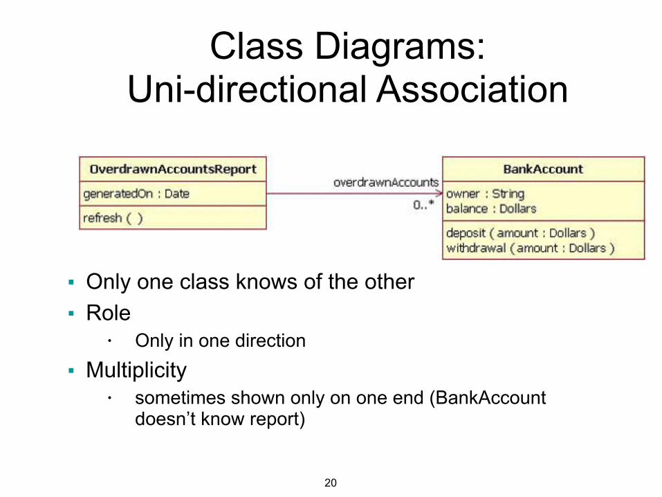
■ Only one class knows of the other ■ Role
• Only in one direction
■ Multiplicity • sometimes shown only on one end (BankAccount
doesn’t know report)
Class Diagrams: Uni-directional Association
21
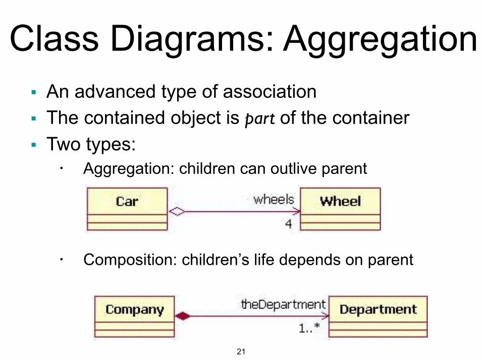
■ An advanced type of association ■ The contained object is part of the container ■ Two types:
• Aggregation: children can outlive parent !!!
• Composition: children’s life depends on parent
Class Diagrams: Aggregation
22
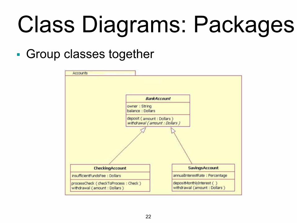
■ Group classes together
Class Diagrams: Packages
23
■ Used to describe sequences of invocations between the objects that comprise the system • Focus less on type of messages, more on the
sequence in which they are received !■ Elements of UML sequence diagrams:
• Lifelines • Messages
Sequence Diagrams
24
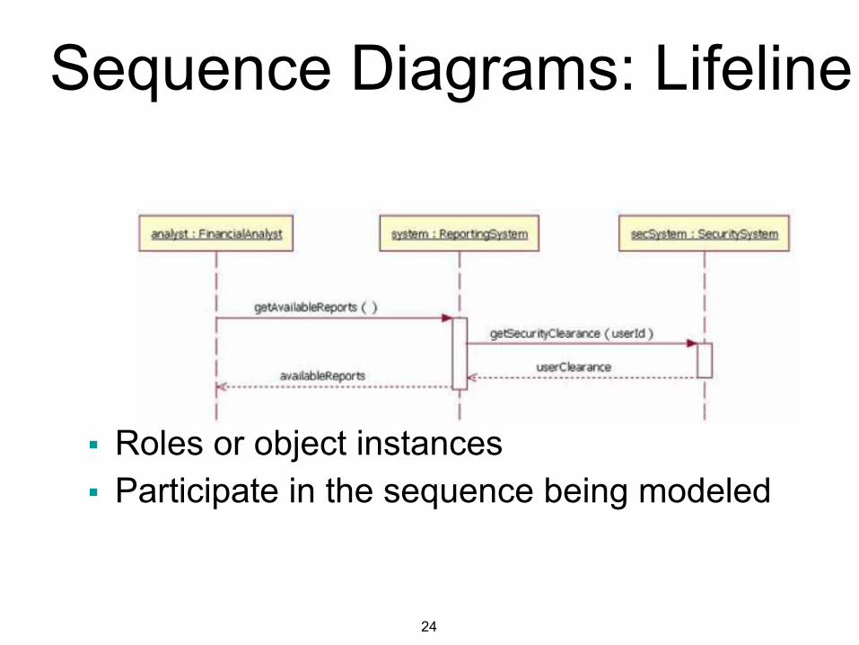
!!!!!
■ Roles or object instances ■ Participate in the sequence being modeled
Sequence Diagrams: Lifeline
25
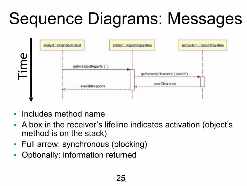
!!!!!
■ Includes method name ■ A box in the receiver’s lifeline indicates activation (object’s
method is on the stack) ■ Full arrow: synchronous (blocking) ■ Optionally: information returned
Time
Sequence Diagrams: Messages
25
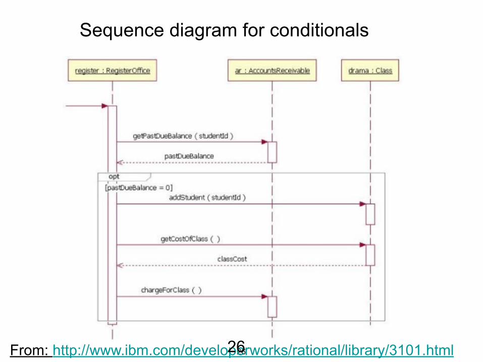
26From: http://www.ibm.com/developerworks/rational/library/3101.html
Sequence diagram for conditionals
26
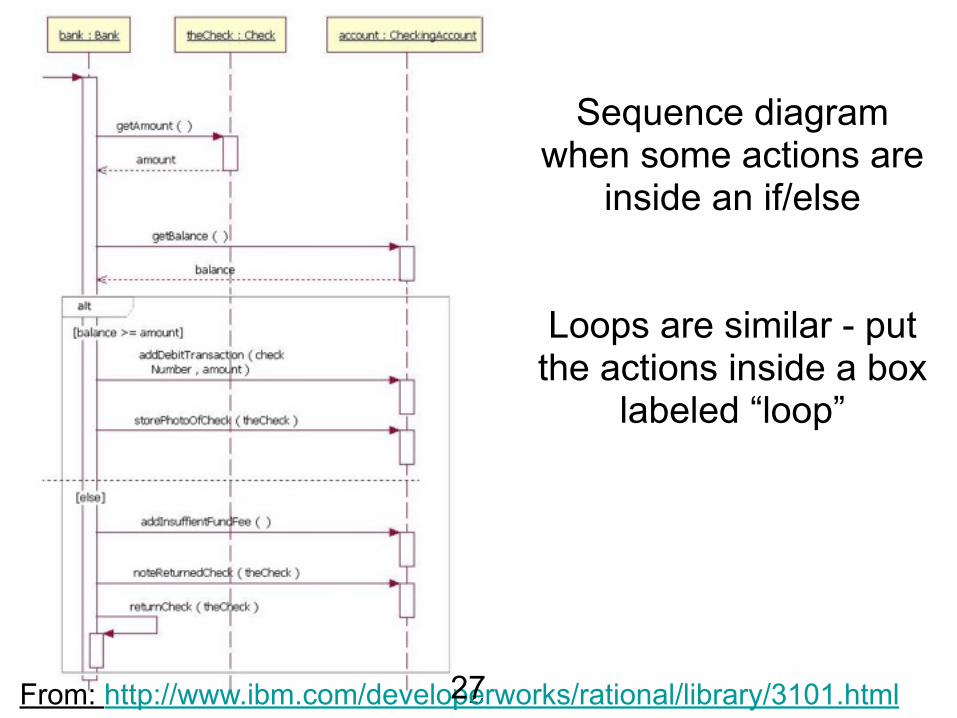
27
Sequence diagram when some actions are
inside an if/else !!
Loops are similar - put the actions inside a box
labeled “loop”
From: http://www.ibm.com/developerworks/rational/library/3101.html27
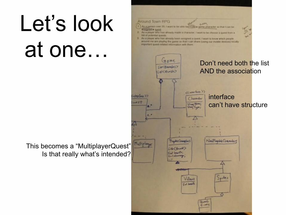
Let’s look at one…
interface can’t have structure
Don’t need both the list AND the association
This becomes a “MultiplayerQuest” Is that really what’s intended?
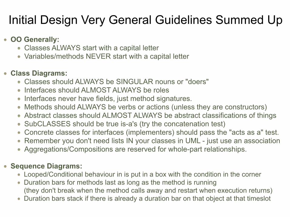
Initial Design Very General Guidelines Summed UpOO Generally:
Classes ALWAYS start with a capital letter Variables/methods NEVER start with a capital letter !
Class Diagrams: Classes should ALWAYS be SINGULAR nouns or "doers" Interfaces should ALMOST ALWAYS be roles Interfaces never have fields, just method signatures. Methods should ALWAYS be verbs or actions (unless they are constructors) Abstract classes should ALMOST ALWAYS be abstract classifications of things SubCLASSES should be true is-a's (try the concatenation test) Concrete classes for interfaces (implementers) should pass the "acts as a" test. Remember you don't need lists IN your classes in UML - just use an association Aggregations/Compositions are reserved for whole-part relationships.
!Sequence Diagrams:
Looped/Conditional behaviour in is put in a box with the condition in the corner Duration bars for methods last as long as the method is running (they don't break when the method calls away and restart when execution returns) Duration bars stack if there is already a duration bar on that object at that timeslot