Embed Size (px)
Citation preview

CP
TMay 2016225-708-00 D
P
C-P
rog
ram
mab
le S
ign
al I
sola
ter/
Co
nver
ter
All product names are registered trademarks of their respective companies.
CPTHLPRG
PC-Programmable SignalIsolater/Converter

Table of Contents
Introduction ............................................................................................................................................. 4
About this Manual ............................................................................................................ 4
The CPT ........................................................................................................................... 4
Model and Serial Numbers............................................................................................... 4
Options ............................................................................................................................. 4
Specifi cations ................................................................................................. 5
Dimensions ...................................................................................................................... 6
Confi guring the CPT ....................................................................................... 7
Installing the Confi guration Software ............................................................................... 8
Connecting the CPT to the PC ........................................................................................ 8
PC Confi guration Software Summary .......................................................... 9
Confi guration ............................................................................................... 10
Output Level if Failure .................................................................................................... 10
Broken Wire Test Override ............................................................................................. 10
Alarms ............................................................................................................................ 11
Trimming/Damping ....................................................................................... 12
Sensor Trim .................................................................................................................... 12
Output Trim ..................................................................................................................... 14
Loop Test ........................................................................................................................ 14
Output Damping ............................................................................................................. 15
Output if Measurement OFF .......................................................................................... 15

Custom Table ................................................................................................ 16
Installation ..................................................................................................... 17
Mounting the CPT .......................................................................................................... 17
Making the Electrical Connections ................................................................................. 17
Recommended Ground Wiring Practices ....................................................................... 17
CE Conformity ................................................................................................................ 17
Operation ....................................................................................................... 17
Maintenance ................................................................................................................... 17

CPT
4 The Interface Solution Experts
PC-Programmable SignalIsolater/Converter
The CPT The CPT is a PC-Programmable, user-confi gurable, transmitter. The instrument includes an analog output and an optional alarm (relay) output. The alarm can be confi gured as a trip or fault alarm. The CPT has a READY LED to indicate the health of the unit, an INPUT LED to indicate the status of the input and a dual color LED to indicate alarm status.
Model and Serial NumbersMoore Industries uses a system of model and serial numbers to keep track of all of the information on every unit it sells and services. If a problem occurs with your CPT, check for a tag affi xed to the unit listing these numbers. Supply the Customer Support representative with this information when calling.
InputsThe current input range of your unit is from 0 – 50mA. The voltage input range is from 0.0 – 10V.
OutputsThe CPT has a factory confi gurable current or voltage output. The curent output range is 0-20mA. The voltage output is 0-10V. An Analog Output (-AO) is standard. The current output is a factory confi gurable sink or source. Please notify Moore Industries of your required confi guration. The output may also be confi gured to narrower spans from the PC Confi guration Program.
TX PowerA transmitter excitation power supply is standard on the CPT (HLPRG). You may access this at the TX and COM terminals. This is a fi xed power supply at 23Vdc, ±3% and 24mA max.
Options
Relay Output (-C)An optional Relay Output (-C) is available. This is a one relay output with 5A@250Vac or 5A@24Vdc, 50/60Hz non-inductive contact rating. The relay contact arrangement is SPDT. All relay contacts (NO, NC and COM) are available for use. No jumpers are required.
RF Option (-RF)An RF option is also available. This version provides 30V/m RFI/EMI immunity compared to our standard model which offers 10V/m RFI/EMI immunity.
IntroductionThis is the users’ manual for the Moore Industries CPT PC-Programmable Transmitter (HLPRG: Volt and Milliamp input limits). It contains all of the information needed to confi gure, install, operate, and maintain this instrument.
About this ManualWherever you see a “ Note”, “ Caution”, or “ WARNING ” pay particular attention.
WARNING - Hazardous procedure or condition that could injure the operator.
Caution - Hazardous procedure or condition that could damage or destroy the unit.
Note - Information that is helpful for a procedure, condition, or operation of the unit.
Figure 1. The CPT (HLPRG)
INPUT
READY
ALARM
COM
COMPUTER PROGRAMMABLE TRANSMITTER

The Interface Solution Experts 5
CPTPC-Programmable Signal
Isolater/Converter
Specifi cations and information subject to change without notice.
Specifi cations Input Accuracy: Current, ±0.01% of max. span (±2 microamps); Voltage, ±0.01% of max. span (±1mV)Output Accuracy: Current, ±0.01% of max span (±2 microamps); Voltage, ±0.01% of max. span (±1mV)Overall Accuracy: The overall accuracy of the unit is the combined input and output (if any) accuracies. It includes the combined effects of linearity, hysteresis, repeatability, and adjustment resolution. It does not include ambient temperature effect Mimimum Span at Specifi ed Accuracy: Current, 4mA; Voltage, 1VStability: See Table 1 Response Time: 256msec maximum (128msec typical) for the output to change from 10 to 90% of its scale for an input step change of 0 to 100% Ripple: 50mVp-p maximum on voltage output; 10mVp-p measured across a 250 ohm load resistor for current output (Frequencies up to 120Hz)Output Limiting: Input over range, -0.2V/0mA and 10.5V/21.4mA; Input failure, -0.5V/0mA and 11V/24mAOutput CurrentLimiting: 25mA max.Load Effect: 0.01% of span from 0 to maximum load resistance
Maximum Load Resistance: 1kohmLine Voltage Effect: ±0.002% of span per 1% change in line voltage (ac or dc)Isolation: Standard unit, 1000Vrms between case, input and output. 1500Vrms between power and input and between power and output; Unit with -RF option, 500Vrms between case, input, output and powerPower Consumption: 2.5W typical, 3W max.Power Supply Effect: ±0.002% of span per 1% of line changeInput Impedance: 20ohms for current inputs; 1.1Mohm for voltage inputs Input Over-Range Protection: ±100mA for current inputs; ±30Vdc for voltage inputs
WITH ALARM TRIP OUTPUT: Alarm Trip Repeatability: Current, ±0.01% of max. span (±2microamps); Voltage, ±0.01% of max. span (±1 mV)Response Time: 300msec (Defi ned as time from step change on input to alarm state change when alarm is set to trip midpoint)Alarm Deadband: Programmable from0-100% of input rangeAlarm Trip Delay: 0-120 seconds
LED Type: INPUT LED: Dual color LED indicates input failureREADY LED: Green LED indicates unit is operating properlyALARM 1 LED: Dual color LED indicates alarm status
Operating & Storage Range: -40°C to +85°C (-40°F to +185°F)Relay Range: -25°C to +70°C (-13°F to +158°F)Relative Humidity: 0-95%, non-condensingAmbient Temperature Effect: ±0.015% of maximum span/°CRFI/EMI Immunity (Standard Unit): 10V/m@20-1000MHz, 1kHz when tested according to IEC1000-4-3-1995 with 0.5% of span or less errorRFI Immunity (with -RF Option): 30V/m@20-1000MHz, 1kHz AM when tested according to IEC1000-4-3-1995 with 0.5% of span or less errorNoise Rejection: Common mode: 100dB@50/60Hz; Normal Mode: Current Input, 100dB typical at 50mAp-p@50/60Hz; Voltage Input, 100dB typical at 1Vp-p@50/60Hz
535 g (17.2 oz)
Performance Indicators
AmbientConditions
Weight
Performancewith Alarm
Trip (-C Option)
Performance(continued)
Table 1. Long-Term Stability
Current Inputs
Voltage Inputs
Input-to-Analog Output (Years)
Input-to-RelayOutput (Years)
Stability (% of maximum
span) 1
0.081
0.093
3
0.14
0.16
5
0.18
0.21
1
0.047
0.066
3
0.081
0.114
5
0.105
0.147

CPT
6 The Interface Solution Experts
PC-Programmable SignalIsolater/Converter
Figure 2. CPT (HLPRG) Dimensions
INPUT
READY
ALARM 100mm(3.94 in)
124mm
53mm(2.09 in)
48mm(1.89 in)
CL
136mm(5.36 in)
131mm(5.16 in)
WHEN INSTALLED
WHEN INSTALLED
35mm(1.38 in) (4.89 in)
COM
COMPUTERPROGRAMMABLETRANSMITTER
Table 2. Terminal Designations
Input Type
Current Input (HLPRG)
Voltage Input (HLPRG)
Top Terminals (Left to Right)
T1 T2 T3 T4 T5 T6
KEY:AC/DC = Power InputACC/DCC = Power Input CM = Relay CommonCOM = Analog CommonGND = Ground
NOTES:1. Terminal blocks can accomodate 14-22 AWG solid wiring.2. NO/CM/NC labeling is present only when the unit is equipped with the Alarm Trip (-C) option.
Power/Options
Standard Unit
With Alarm Trip (-C) Option
Bottom Terminals (Left to Right)
B1 B2 B3 B4 B5 B6
I = Current InputV = Voltage Input OUT = Current OutputNO = Normally OpenNC = Normally Closed
SPDT = Single-Pole/Double-ThrowTX = Power for 2-wire transmitter
Tx +I COMNot
Used+OUT –OUT
+OUT –OUTNotUsed
NotUsed
COM +V
NotUsed ACC/DCC GND
NotUsed
NotUsed AC/DC
ACC/DCC GNDAC/DCCM NCNO
The Interface Solution Experts 7
CPTPC-Programmable Signal
Isolater/Converter
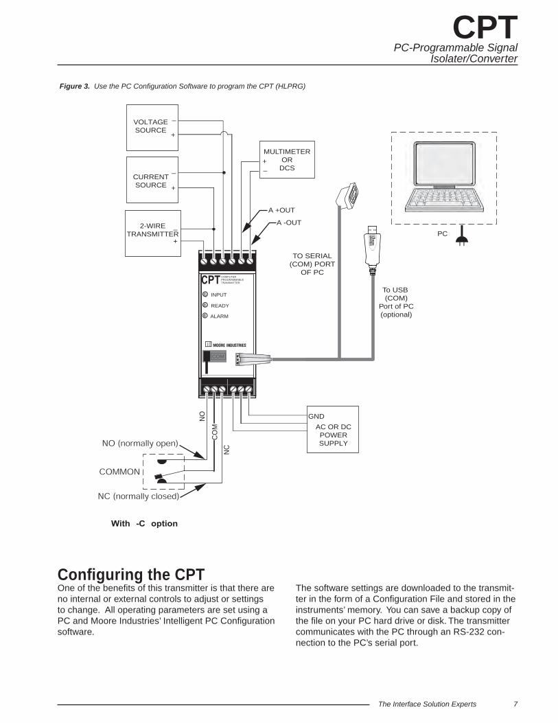
Figure 3. Use the PC Confi guration Software to program the CPT (HLPRG)
Confi guring the CPT One of the benefi ts of this transmitter is that there are no internal or external controls to adjust or settings to change. All operating parameters are set using a PC and Moore Industries’ Intelligent PC Confi guration software.
The software settings are downloaded to the transmit-ter in the form of a Confi guration File and stored in the instruments’ memory. You can save a backup copy of the fi le on your PC hard drive or disk. The transmitter communicates with the PC through an RS-232 con-nection to the PC’s serial port.
NO
CO
M
TO SERIAL(COM) PORT
OF PC
INPUT
READY
ALARM
COM
COMPUTERPROGRAMMABLETRANSMITTER
VOLTAGESOURCE
_
+
CURRENTSOURCE
_
+
2-WIRETRANSMITTER
_
+
AC OR DCPOWERSUPPLY
GND
NC
PC
+–
MULTIMETEROR
DCS
A -OUT
A +OUT
To USB (COM)
Port of PC(optional)

CPT
8 The Interface Solution Experts
PC-Programmable SignalIsolater/Converter
Table 3. Assembling the equipment needed to confi gure the CPT (HLPRG)
Connecting the CPT to the PCConnect the RS-232 end of the cable to the PC’s COM port.
See Table 3 for information on the necessary equipment
Installing the Confi guration SoftwareRefer to Table 3 for the equipment needed.
1. Insert the Moore Industries Interface Solution PC Confi guration Software CD into the CD drive of the PC. Access the CD and open the “CPA CPT PC Confi guration Software” folder.
2. Double-click the installation program located in the folder. Follow the prompts to correctly install the program.
Once the Confi guration Program is installed on the PC, the CPT can be connected to equipment to simulate input and monitor output. You can then change the transmitter’s operating parameters.
No Transmitter NeededIt is not necessary to connect the transmitter to a PC to create confi guration fi les using the software. The Confi guration Program can be run without connecting a transmitter, and most parameters can be set without benefi t of input from a CPT.
This makes it easy to create a set of operating parameters, save them to disk, and download them to one or more transmitters at a later time.
The CPT must be connected to the PC in order to: trim input, trim output, assign a tag, perform a loop test, receive (via download) a confi guration fi le, and save the confi guration fi le from the transmitter’s memory.
Power Supply 24Vdc, ±10% or 117/230Vac (depending on confi guration)
Device Specifi cations
Accurate to ±0.009% of span; e.g., HP Model 3478A
80386-based(or faster) IBM PC, or 100% compatible;4Mb free RAM; 8Mb recommended; 20Mb free disk space on hard drive (More RAM & hard disk space is required for Windows NT, 2000, XP, Vista, or 7)Microsoft Windows® NT, 2000, XP, Vista, or 7Internet Explorer 3.0+ 1 (one) serial port (COM 1, 2, 3, or 4) set to 9600 baud, no parity, 8 data bits, and 1 stop bit or one available USB port (with optional USB cable)
Version 1.0 or greater, successfully installed to the hard driveMoore Industries PC
Confi guration Software
Communication Cable
Current or Voltage Source Accurate to 0.05% of span for the intended application
Multimeter (optional)
Personal Computer
Part# 803-053-26 or optional USB cable, Part# 208-236-00A

The Interface Solution Experts 9
CPTPC-Programmable Signal
Isolater/Converter
Figure 4. Most of the CPT (HLPRG) Operating Parameters can be set from the Main Screen of the Confi guration Program
Once the default confi guration has been saved to disk, it is safe to program other parameters. The PC Soft-ware is made up of these sections:
1. Status– This portion of the program displays the activity of the connected unit. It will show the COM Port being used and the Measurement Mode.
2. Measurements– Displays current software pro-cesses and indications. Allows you to select the deci-mal place of your process variable (Decimal Places (PV)) indication and monitor up to two confi guration variables (Monitored Vars).
3. Device Information– This “read-only” display indicates fi rmware version, hardware revision, serial number, calibration date, software version and con-fi guration date and the last confi guration source.
4. Communication– From here you may enable Start Measurements and Stop Measurements, upload your confi guration to PC or download your confi guration to the unit, save your confi guration to a fi le, and print out your confi guration settings.
5. Input Confi guration– Select 50/60Hz Rejection Selection. Allows you to choose input type. You may also enable Input Trim, Output Trim, Custom Table and Broken Wire Test functions.
6. Device Confi guration– Use this parameter to place an identifying “Message” (32 alphanumeric characters max.), select an “I.D. Tag” (8 alphanumeric characters max.) and a “Descriptor” (16 alphanumeric characters max.).
7. Output Confi guration– Use this section to select your output confi guration and output limits.
8. Output Level if Failure– Used to select confi gu-ration of Upscale/Downscale Drive failure detection. Refer to Output Level if Failure section for a complete description.
9. Broken Wire Test Override– Allows you to enable or disable the Broken Wire Test Override feature by clicking the “BW ON” or “BW OFF” buttons. Refer to the Broken Wire Test Override section for a complete description.
PC Confi guration Software Summary
1
2
3
4
5
6
7
8
9
11 12
10

CPT
10 The Interface Solution Experts
PC-Programmable SignalIsolater/Converter
10. Alarm Parameters– Use this to choose an alarm mode and confi gure as either a Trip, Fault or Band alarm. Select whether to use as a Fail Safe or NON Fail Safe Alarm. You may also choose a Delay (0-120sec) and a Deadband (0-100%). Refer to the Alarms section for a complete description.
11. Trimming/Damping Tab– Selecting this parameter allows you to perform Sensor Trim, Output Trim and Output Damping functions. Refer to the Trimming/Damping section for a complete description.
12. Custom Table Tab– The CPT has two modes of operation: linear mode and custom mode. In linear mode, the scaled output is proportional to the scaled input. In custom mode, reached by selecting the Custom Table Tab, you defi ne a special linearization function. Refer to the Custom Table section for a complete description.
Confi guration
Output Level if Failure In the Output Level if Failure section you will notice Down Scale and Up Scale selection. Using its output, the CPA can be confi gured to provide a special warning of a breakdown or failure. Use this setting to confi gure the instrument to drive its output either up or down when a failure is detected. For current outputs, limits are 3.6mA (downscale) and 23.6mA (upscale); for voltage outputs, limits are -0.5V (downscale) and 11.0V (upscale).
When a failure is detected, the “Fail Last” feature, if enabled, holds the last measured value before the failure occurred.
If the “User Selected” feature is enabled, you may enter any value, within the range, to view at the output when a failure is detected.
Broken Wire Test OverrideThe CPT monitors your primary variable. If the monitored value falls equal to or below a set value, then a state of Broken Wire is declared.
Select the value of the primary variable which will be considered “failure” and place it in the “Broken Wire Level” text box. The range of this value must be higher than zero (0.00mA or 0.00V) and less than the “Zero Input Range”. Normally, a value of 0.1 or 0.2 is suffi cient.
When a failure is detected, “Broken Wire Failure” in the Process Information section will light along with the associated “Broken Wire” light(s) to indicate a problem.
If you are using the Trip or Band Alarm function, your alarm status will remain unchanged as a result of the failure. If the Fault Alarm is enabled, the alarm is activated and resets once the failure has been corrected.
In order to activate Broken Wire detection, you must check the “BW ON” box and enter your selected “failure” value.
Note:Once you have confi gured all parameters,
download to the unit by either selecting “Download Confi guration” in the Confi guration dropdown menu located in the Communications bar or by clicking the
button.

The Interface Solution Experts 11
CPTPC-Programmable Signal
Isolater/Converter
Alarms
Trip Low and Trip High AlarmsIn the Alarm Parameters portion of our CPT Confi guration Program you may choose a “Trip Low” and “Trip High” limit. In choosing your limits you are setting the parameters for your unit to notify you if your process input drops below (Trip Low) or exceeds (Trip High) your trip point setting.
DeadbandDeadband (0-100%) is a type of buffer zone. It allows an alarm to remain tripped even after the process input has returned to, or passed, the trip point. If no deadband is set, the alarm will reset itself once reaching the trip point.
Fail Safe/NON Fail Safe AlarmsA Fail Safe alarm, if in the alarm condition, will remain in the alarm condition even if power to the unit is removed.
Fail Safe alarm trip relays are energized whenever the process input is in a non-alarm condition (including any deadband setting). These relays de-energize when the process input trips the alarm.
NON Fail Safe alarm trip relays are energized whenever the process input is in an alarm condition. These relays de-energize when the process input returns to the reset point (including any deadband).
Band AlarmThe Band Alarm incorporates Low and High Trip points, Deadband and Delay (0-120sec).
The Band Alarm combines two Trip Alarm settings. The fi rst alarm is always confi gured as Low Trip (Trip Point Low) and the second as High Trip (Trip Point High). See Figure 5 for information on alarm parameters.
The Band Alarm is activated when the Process Variable is outside of the Low/High Trip point ranges. The Trip Low is always lower than the Trip High and their deadbands are inside the range of Low/High Trip. The span between the Low and High Trip is not limited, which allows control of measurements in a very narrow range.
Fault AlarmTo simply be alerted in the case of any fault that may arise, select the “Fault Alarm” button. This requires no parameters to be set and will notify you anytime a fault is sensed.
Note:Once you have confi gured all parameters,
download to the unit by either selecting “Download Confi guration” in the Confi guration dropdown menu located in the Communications bar or by clicking the
button.
Figure 5. Band Alarm Parameter Graph

CPT
12 The Interface Solution Experts
PC-Programmable SignalIsolater/Converter
Figure 6. PC Confi guration Software Trimming/Damping Tab
Trimming/Damping
To access the Trim feature, click the Trimming/Damping tab . Trimming increases the measurement accuracy of the parameter you are trimming by either matching the reading of its actual input to its scaling (Sensor Trimming) or calibrating the output to the device receiving the output (Output Trimming). Damping allows you to introduce a delay into the response of your transmitter in order to stop short-lived spikes from setting off alarms. Refer to Figure 7 for hookup.
Sensor TrimSensor Trimming increases the measurement accuracy of your CPT by matching the reading of its actual input to either a calibrated source or the device to which it is connected. This verifi es that the input from the sensor to the alarm is being interpreted correctly.
The CPT can trim any point along the scale. Note that one-point trimming applies an offset to the sensor reading, while two-point trimming applies both an offset and a gain.
Before you attempt to perform the Sensor Trim function ensure that the Status section of the screen indicates “Measurements On”. Sensor Trim can be done only when the measurements are on. To do this click the Mode dropdown box, from the menu bar, and select “Measurements On”.
1. Select either one trim point or two trim points by clicking the appropriate button. Each pair consists of “trim” and “captured” values.
2. Enter the values that need to be trimmed into the corresponding fi elds.
3. Apply the targeted signal to the input, wait until it settles and click “Point 1 Trim” to capture the measured value. If you chose “Two-point Trim” repeat the step above for the second point and click “Point 2 Trim”.
4. To enable input trim and the values stored, click the “Input Trim ON”.

The Interface Solution Experts 13
CPTPC-Programmable Signal
Isolater/Converter
Figure 7. Trimming the CPT (HLPRG)
+–
MULTIMETEROR
DCS
NO
INPUT
READY
ALARM
COM
COMPUTERPROGRAMMABLETRANSMITTER
VOLTAGESOURCE
_
+
CURRENTSOURCE
_
+
_
+
AC OR DCPOWERSUPPLY
GND
CO
M
NC
2-WIRETRANSMITTER
A -OUT
A +OUT

CPT
14 The Interface Solution Experts
PC-Programmable SignalIsolater/Converter
Output TrimOutput Trimming increases the measurement accuracy of your CPT by calibrating its output to the device that is receiving the output. This ensures that the instrument is being correctly interpreted.
Before you attempt to perform the Output Trim function ensure that the Status section of the screen indicates “Measurements Off”. To do this click the Mode dropdown box, from the menu bar, and select “Measurements Off”.
1. Review your Model Number label to determine if your unit is built for Current (0-20mA) or Voltage (0-10V) output.
2. Attach a multimeter to the analog output and select the “4mA” or “0V” button (whichever is appropriate). Use the scroll bar to trim the measured output to your desired value.
3. With the multimeter still connected select the “20mA” or “10V” button (whichever is appropriate). Use the scroll bar to trim the measured output to your desired value.
4. To enable Output Trim and the values stored, click the “Output Trim ON”.
5. Set Status back to “Measurements On”.
If selected, the User trim values will be used and the manufacturer settings will be nullifi ed.
Loop TestA Loop Test may be performed in order to check output performance and accuracy and to trim other instruments in the loop. Your output will be a current value, in mA, or a voltage equal to the value you input. You can check the other current devices on the loop and calibrate them to this signal.
This feature is independent of the input. If you fi nd that the output requires adjustment you may perform the Output Trim function.
1. To use the Loop Test function select the Mode dropdown box in the Communications bar and select “Measurements Off”.
2. Next, in the “Output Value %” box, type the percentage of the output value you wish to test. You may also use your mouse, left click and adjust the scroll bar to adjust to your desired value. Hit “Enter”.
3. In the “Output Value” box enter the value, within your confi guration range, that you wish to signify as your output value. Hit “Enter”.
4. Perform your test and calibration.
5. When you are fi nished, return to Mode in the Communications bar and reset your status to “Measurements On”.

The Interface Solution Experts 15
CPTPC-Programmable Signal
Isolater/Converter
Output if Measurement OFFChoose “Zero Range” to read zero volts or mA at output if measurement was off.
Choose “Stay Last” to read the last value held before the measurement was off.
Note:Once you have confi gured all parameters,
download to the unit by either selecting “Download Confi guration” in the Confi guration dropdown menu located in the Communications bar or by clicking the
button.
Output DampingOutput Damping allows you to introduce a delay into the response of your unit in order to stop short-lived spikes from setting off alarms. Output Damping is activated when the value set in the “Output Step Threshold” fi eld is exceeded.
1. To enable output damping, select the “Enabled” button. If you do not wish to use the damping feature, then select “Disabled”.
2. Insert a value between 1 and 16mA in the “Output Step Threshold” fi eld. This is how much of an output step change is allowed in a specifi ed time frame before fl agging the software.
3. Insert a value between .5 and 120sec in the “Damping Sec” fi eld. This is the amount of time it will take for the output to reach 63% of the step output change once the input exceeds the value in the “Output Step Threshold” fi eld.
By checking the appropriate box in the Other Damping Options section, you may also choose to select Output Damping to occur upon power up or start up from a PC, upon broken wire failure detection or upon resolution of broken wire failure.
A typical damping situation would be described as a step change in output which causes the output to go from 5.6mA to 20mA. After fi ve seconds the output reaches 14.58mA which equals 63% of the output step change. This is graphed in Figure 8.
Figure 8. Typical Damping Scenario
In this case, an instrument malfunction or Adc/EEPROM failure may be to blame.
A possible source for the occurence above is a rapid change on the input. Another possiblity would be an existing output level of 5.6mA upon Start Measurements from a PC.
Figure 9 gives another damping example where the output has been driven upscale to 23.6mA. After fi ve seconds the 63% output change is reached at 16.98mA.
Figure 9. Damping When Output Driven Upscale to 23.6mA

CPT
16 The Interface Solution Experts
PC-Programmable SignalIsolater/Converter
Figure 10. PC Confi guration Software Custom Table Tab
The Custom Table feature allows you to setup your own custom curve table (Figure 10). This allows you to tell the CPA what it should output when it receives a certain input. This feature also allows you the ability to write a table in Microsoft® Excel, save it in a .csv format. The fi les are saved to/read to/read from the “Moore Industries\Custom Curves” folder. This makes it simple to save the custom table for downloading to multiple units or for backup purposes.
The linearization will be in the form of X, Y coordinates. You may choose up to 128 points.
To access this function click the Custom Table tab.
1. Select the number of points you are to set and insert this value into the “Number Of Points” line, hit “Enter”. This will highlight the number of points you have selected.
Note:To clear the table and start over at any time, click
“Clear Table”.
2. Type your individual values in the X and Y columns. Source variables are inserted into the X Column while the corresponding data is inserted into the Y Column.
3. To save the displayed custom table to your hard drive click the “Save Table” button.
To open or use this saved table at a later time, click the “Open Table” button and select the folder in which it has been saved.
Use the “Table EGU” box to enter any alphanumeric engineering unit (up to 6 digits).
To use the Custom Table feature in your operation check the “Custom Table ON” box.
Note:Once you have confi gured all parameters,
download to the unit by either selecting “Download Confi guration” in the Confi guration dropdown menu located in the Communications bar or by clicking the
button.
Custom Table

The Interface Solution Experts 17
CPTPC-Programmable Signal
Isolater/Converter
Customer SupportMoore Industries is recognized as the industry leader in delivering top quality to its customers in products and services. We perform a battery of stringent quality assurance checks on every unit we ship. If any Moore Industries product fails to perform up to rated speci-fi cations, call us for help. Our highly skilled staff of trained technicians and engineers pride themselves on their ability to provide timely, accurate, and practical answers to your process instrumentation questions.
Factory phone numbers are listed on the back cover of this manual.
If problems involve a particular CPT, there are several pieces of information that can be gathered before you call the factory that will help our staff get the an-swers you need in the shortest time possible. For the fastest service, gather the complete model and serial number(s) of the problem unit(s) and the job number of the original sale.
InstallationInstallation consists of physically mounting the unit and completing the electrical connections.
Mounting the CPT The CPT can be mounted on standard DIN mounting rails.
Making the Electrical ConnectionsPlease refer to Figure 3 for electrical connections.
Recommended Ground Wiring PracticesMoore Industries recommends the following ground wiring practices:
• Any Moore Industries product in a metal case or housing should be grounded.
• The protective earth conductor must be connected to a system safety earth ground before making any other connections.
• All input signals to, and output signals from, Moore Industries’ products should be wired using a shielded, twisted pair technique. Shields are to be connected to an earth or safety ground at the unit itself.
• The maximum length of unshielded input and/or output signal wiring should be two inches.
CE ConformityInstallation of any Moore Industries’ products that carry the CE certifi cation must adhere to the guidelines above in order to meet the requirements set forth in the European EMC and Low Voltage Directives (EN 61326 and EN 61010). Consult the factory for the most current information on products that have been CE certifi ed.
OperationOnce programmed, calibrated, installed, and supplied with the correct power, the CPT transmitter begins to operate immediately. Depending upon environmental conditions, it can be expected to operate unattended for extended periods of time.
MaintenanceMoore Industries suggests a check for terminal tightness and general unit condition every 6-8 months. Always adhere to any site requirements for programmed maintenance.

WARRANTY DISCLAIMERTHE COMPANY MAKES NO EXPRESS, IMPLIED OR STATUTORY WAR-RANTIES (INCLUDING ANY WARRANTY OF MERCHANTABILITY OR OF FITNESS FOR A PARTICULAR PURPOSE) WITH RESPECT TO ANY GOODS OR SERVICES SOLD BY THE COMPANY. THE COMPANY DIS-CLAIMS ALL WARRANTIES ARISING FROM ANY COURSE OF DEALING OR TRADE USAGE, AND ANY BUYER OF GOODS OR SERVICES FROM THE COMPANY ACKNOWLEDGES THAT THERE ARE NO WARRANTIES IMPLIED BY CUSTOM OR USAGE IN THE TRADE OF THE BUYER AND OF THE COMPANY, AND THAT ANY PRIOR DEALINGS OF THE BUYER WITH THE COMPANY DO NOT IMPLY THAT THE COMPANY WARRANTS THE GOODS OR SERVICES IN ANY WAY. ANY BUYER OF GOODS OR SERVICES FROM THE COMPANY AGREES WITH THE COMPANY THAT THE SOLE AND EXCLUSIVE REMEDIES FOR BREACH OF ANY WARRANTY CONCERNING THE GOODS OR SERVICES SHALL BE FOR THE COMPANY, AT ITS OPTION, TO REPAIR OR REPLACE THE GOODS OR SERVICES OR REFUND THE PURCHASE PRICE. THE COMPANY SHALL IN NO EVENT BE LIABLE FOR ANY CONSEQUENTIAL OR INCIDENTAL DAMAGES EVEN IF THE COMPANY FAILS IN ANY AT-TEMPT TO REMEDY DEFECTS IN THE GOODS OR SERVICES , BUT IN SUCH CASE THE BUYER SHALL BE ENTITLED TO NO MORE THAN A REFUND OF ALL MONIES PAID TO THE COMPANY BY THE BUYER FOR PURCHASE OF THE GOODS OR SERVICES.
RETURN PROCEDURESTo return equipment to Moore Industries for repair, perform the following:
1. Notify the local Moore Industries’ Sales Representative or a factory Customer Service Repre-sentative that you are returning equipment for repair. Furnish the Moore Industries’ represen-tative with the model and serial number(s) of the equipment to be returned.
2. In a cover letter or note, describe completely the following:
a. the symptoms that indicate the equipment needs repair
b. the environment in which the equipment has been operating (vibration, temperature, etc.)
c. approximate number of operating hours or approximate installation date (if known)
d. complete shipping information for return of the equipment after repair
e. the name and phone number of the person to contact if questions arise at the factory
3. Enclose the cover letter, packing list, copies of rejection or discrepancy reports (if available), and purchase order or purchase order number with the equipment.
4. Use suffi cient packing material and carefully pack the equipment in a sturdy shipping contain-er.
5. Ship the equipment to the Customer Service Department nearest you.
The returned equipment will be inspected and tested at the factory. A Moore Industries’ represen-tative will contact the person designated in the cover letter if more information is needed.
In case of repair pursuant to Moore Industries’ return policy, the defective equipment will be either replaced, or the purchase price refunded, at Moore Industries option. The equipment or its replacement will be returned to you in accordance with the shipping instructions furnished in your cover letter.
In other cases, the Moore Industries’ representative will advise you of the repair cost and esti-mated return date, if requested in your letter. Repair in such instances must be authorized by a purchase order number before the equipment can be repaired and returned.
ANY CAUSE OF ACTION FOR BREACH OF ANY WARRANTY BY THE COMPANY SHALL BE BARRED UNLESS THE COMPANY RECEIVES FROM THE BUYER A WRITTEN NOTICE OF THE ALLEGED DEFECT OR BREACH WITHIN TEN DAYS FROM THE EARLIEST DATE ON WHICH THE BUYER COULD REASONABLY HAVE DISCOVERED THE ALLEGED DEFECT OR BREACH, AND NO ACTION FOR THE BREACH OF ANY WARRANTY SHALL BE COMMENCED BY THE BUYER NO LATER THAN TWELVE MONTHS FROM THE EARLIEST DATE ON WHICH THE BUYER COULD REASONABLY HAVE DISCOVERED THE ALLEGED DEFECT OR BREACH.
RETURN POLICYFor a period of thirty-six (36) months from the date of shipment, and under normal conditions of use and service, Moore Industries (“The Company”) will at its option replace, repair or refund the purchase price for any of its manufactured products found, upon return to the Company (transportation charges prepaid and otherwise in accordance with the return procedures established by The Company), to be defective in material or workmanship. This policy extends to the original Buyer only and not to Buyer’s customers or the users of Buyer’s products, unless Buyer is an engineering contractor in which case the policy shall extend to Buyer’s immediate customer only. This policy shall not apply if the product has been subject to alteration, misuse, accident, neglect or improper application, installation, or operation. THE COMPANY SHALL IN NO EVENT BE LIABLE FOR ANY INCIDENTAL OR CONSEQUENTIAL DAMAGES.
Specifi cations and information subject to change without notice.© 2005 Moore Industries-International, Inc.