Embed Size (px)
Citation preview
DEEN
DEEN
DEEN
DEEN
DEEN
DEEN
DEEN
DEEN
DE
BetriebsanleitungOperating instructions Additional languages www.stahl-ex.com
DE EN
CPU & Power Modul für Zone 1 / Div. 1
CPU & Power Module for Zone 1 / Div. 1
Reihe 9440/22, 9490
Series 9440/22, 9490


DEDEDEDEDEDEDEDEDEDEDEDEDEDEDEDEDEDEDEDEDEDEDEDEDE
BetriebsanleitungAdditional languages www.stahl-ex.com
DE
CPU & Power Modul für Zone 1 / Div. 1
Reihe 9440/22, 9490
2 162277 / 94406073102016-03-24·BA00·III·de·05
CPU & Power Modul für Zone 1 / Div. 1Reihe 9440/22, 9490
DEDEDEDEDEDEDEDEDEDEDEDEDEDEDEDEDEDEDEDEDEDEDEDEDE
Inhaltsverzeichnis1 Allgemeine Angaben ...........................................................................................31.1 Hersteller .............................................................................................................31.2 Angaben zur Betriebsanleitung ...........................................................................31.3 Weitere Dokumente ............................................................................................31.4 Konformität zu Normen und Bestimmungen .......................................................32 Erläuterung der Symbole ....................................................................................42.1 Symbole in der Betriebsanleitung .......................................................................42.2 Warnhinweise .....................................................................................................42.3 Symbole am Gerät ..............................................................................................53 Sicherheitshinweise ............................................................................................53.1 Aufbewahrung der Betriebsanleitung ..................................................................53.2 Sichere Verwendung ...........................................................................................53.3 Umbauten und Änderungen ................................................................................64 Funktion und Geräteaufbau ................................................................................64.1 Funktion ..............................................................................................................74.2 Geräteaufbau ......................................................................................................75 Technische Daten ...............................................................................................86 Projektierung .....................................................................................................136.1 Hilfsenergieanschluss .......................................................................................136.2 Sub-D-Buchsen X1, X2, X3 ..............................................................................147 Transport und Lagerung ...................................................................................148 Montage und Installation ...................................................................................158.1 Maßangaben / Befestigungsmaße ....................................................................168.2 Montage / Demontage, Gebrauchslage ............................................................178.3 Installation .........................................................................................................199 Parametrierung und Inbetriebnahme ................................................................209.1 Parametrierungen .............................................................................................2010 Betrieb ...............................................................................................................2210.1 Betrieb ...............................................................................................................2210.2 Anzeigen ...........................................................................................................2210.3 Fehlerbeseitigung .............................................................................................2711 Instandhaltung, Wartung, Reparatur .................................................................2811.1 Instandhaltung ..................................................................................................2811.2 Wartung ............................................................................................................2811.3 Reparatur ..........................................................................................................2811.4 Rücksendung ....................................................................................................2912 Reinigung ..........................................................................................................2913 Entsorgung ........................................................................................................2914 Zubehör und Ersatzteile ...................................................................................29
162277 / 94406073102016-03-24·BA00·III·de·05
Allgemeine Angaben
3
DEDEDEDEDEDEDEDEDEDEDEDEDEDEDEDEDEDEDEDEDEDEDEDEDE
CPU & Power Modul für Zone 1 / Div. 1Reihe 9440/22, 9490
1 Allgemeine Angaben
1.1 HerstellerR. STAHL Schaltgeräte GmbHAm Bahnhof 3074638 Waldenburg Germany
Tel.: +49 7942 943-0Fax: +49 7942 943-4333Internet: www.stahl-ex.comE-Mail: [email protected]
1.2 Angaben zur BetriebsanleitungID-Nr.: 162277 / 9440607310Publikationsnummer: 2016-03-24·BA00·III·de·05
Die Originalbetriebsanleitung ist die englische Ausgabe.Diese ist rechtsverbindlich in allen juristischen Angelegenheiten.
1.3 Weitere Dokumente• Datenblatt• Kopplungsbeschreibung IS1 (Download unter www.stahl-ex.com)Dokumente in weiteren Sprachen, siehe www.stahl-ex.com.
1.4 Konformität zu Normen und BestimmungenSiehe Zertifikate und EG-Konformitätserklärung: www.stahl-ex.com.Das Gerät verfügt über eine IECEx-Zulassung. Siehe IECEx-Homepage: http://iecex.iec.ch/Weitere nationale Zertifikate stehen unter dem folgenden Link zum Download bereit: http://www.r-stahl.com/downloads/certificates.html.
Erläuterung der Symbole
4 162277 / 94406073102016-03-24·BA00·III·de·05
CPU & Power Modul für Zone 1 / Div. 1Reihe 9440/22, 9490
DEDEDEDEDEDEDEDEDEDEDEDEDEDEDEDEDEDEDEDEDEDEDEDEDE
2 Erläuterung der Symbole
2.1 Symbole in der Betriebsanleitung
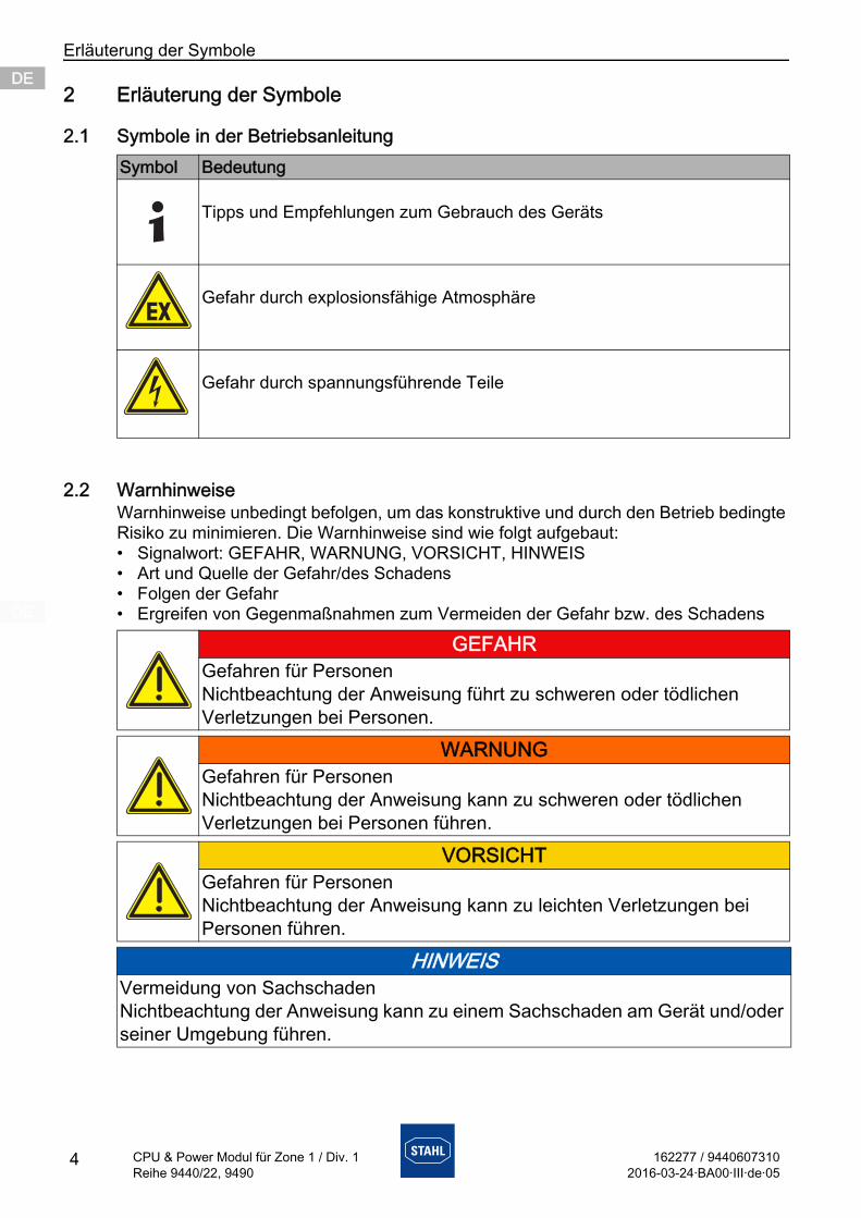
2.2 WarnhinweiseWarnhinweise unbedingt befolgen, um das konstruktive und durch den Betrieb bedingte Risiko zu minimieren. Die Warnhinweise sind wie folgt aufgebaut:• Signalwort: GEFAHR, WARNUNG, VORSICHT, HINWEIS• Art und Quelle der Gefahr/des Schadens• Folgen der Gefahr• Ergreifen von Gegenmaßnahmen zum Vermeiden der Gefahr bzw. des Schadens
Symbol Bedeutung
Tipps und Empfehlungen zum Gebrauch des Geräts
Gefahr durch explosionsfähige Atmosphäre
Gefahr durch spannungsführende Teile
GEFAHRGefahren für PersonenNichtbeachtung der Anweisung führt zu schweren oder tödlichen Verletzungen bei Personen.
WARNUNGGefahren für PersonenNichtbeachtung der Anweisung kann zu schweren oder tödlichen Verletzungen bei Personen führen.
VORSICHTGefahren für PersonenNichtbeachtung der Anweisung kann zu leichten Verletzungen bei Personen führen.
HINWEISVermeidung von SachschadenNichtbeachtung der Anweisung kann zu einem Sachschaden am Gerät und/oder seiner Umgebung führen.
162277 / 94406073102016-03-24·BA00·III·de·05
Sicherheitshinweise
5
DEDEDEDEDEDEDEDEDEDEDEDEDEDEDEDEDEDEDEDEDEDEDEDEDE
CPU & Power Modul für Zone 1 / Div. 1Reihe 9440/22, 9490
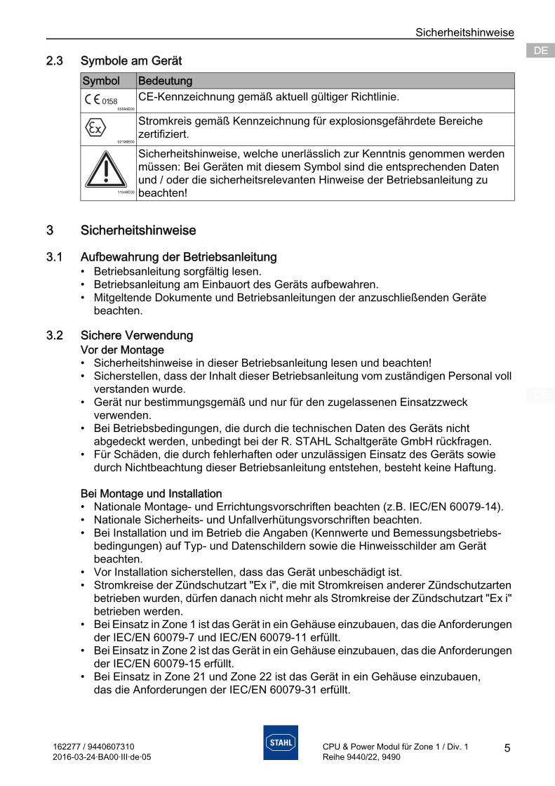
2.3 Symbole am Gerät
3 Sicherheitshinweise
3.1 Aufbewahrung der Betriebsanleitung• Betriebsanleitung sorgfältig lesen.• Betriebsanleitung am Einbauort des Geräts aufbewahren.• Mitgeltende Dokumente und Betriebsanleitungen der anzuschließenden Geräte
beachten.
3.2 Sichere VerwendungVor der Montage• Sicherheitshinweise in dieser Betriebsanleitung lesen und beachten!• Sicherstellen, dass der Inhalt dieser Betriebsanleitung vom zuständigen Personal voll
verstanden wurde.• Gerät nur bestimmungsgemäß und nur für den zugelassenen Einsatzzweck
verwenden.• Bei Betriebsbedingungen, die durch die technischen Daten des Geräts nicht
abgedeckt werden, unbedingt bei der R. STAHL Schaltgeräte GmbH rückfragen.• Für Schäden, die durch fehlerhaften oder unzulässigen Einsatz des Geräts sowie
durch Nichtbeachtung dieser Betriebsanleitung entstehen, besteht keine Haftung.
Bei Montage und Installation• Nationale Montage- und Errichtungsvorschriften beachten (z.B. IEC/EN 60079-14).• Nationale Sicherheits- und Unfallverhütungsvorschriften beachten.• Bei Installation und im Betrieb die Angaben (Kennwerte und Bemessungsbetriebs-
bedingungen) auf Typ- und Datenschildern sowie die Hinweisschilder am Gerät beachten.
• Vor Installation sicherstellen, dass das Gerät unbeschädigt ist.• Stromkreise der Zündschutzart "Ex i", die mit Stromkreisen anderer Zündschutzarten
betrieben wurden, dürfen danach nicht mehr als Stromkreise der Zündschutzart "Ex i" betrieben werden.
• Bei Einsatz in Zone 1 ist das Gerät in ein Gehäuse einzubauen, das die Anforderungen der IEC/EN 60079-7 und IEC/EN 60079-11 erfüllt.
• Bei Einsatz in Zone 2 ist das Gerät in ein Gehäuse einzubauen, das die Anforderungen der IEC/EN 60079-15 erfüllt.
• Bei Einsatz in Zone 21 und Zone 22 ist das Gerät in ein Gehäuse einzubauen, das die Anforderungen der IEC/EN 60079-31 erfüllt.
Symbol Bedeutung
05594E00
CE-Kennzeichnung gemäß aktuell gültiger Richtlinie.
02198E00
Stromkreis gemäß Kennzeichnung für explosionsgefährdete Bereiche zertifiziert.
11048E00
Sicherheitshinweise, welche unerlässlich zur Kenntnis genommen werden müssen: Bei Geräten mit diesem Symbol sind die entsprechenden Daten und / oder die sicherheitsrelevanten Hinweise der Betriebsanleitung zu beachten!
Funktion und Geräteaufbau
6 162277 / 94406073102016-03-24·BA00·III·de·05
CPU & Power Modul für Zone 1 / Div. 1Reihe 9440/22, 9490
DEDEDEDEDEDEDEDEDEDEDEDEDEDEDEDEDEDEDEDEDEDEDEDEDE
• Bei der Installation nach NEC ist die Control drawing zu beachten!• Eigensichere und nicht-eigensichere Feldstromkreise nur in getrennten Kabelkanälen
führen.• Zwischen den Anschlussstellen eigensicherer und nicht-eigensicherer Stromkreise
Mindestabstand oder Fadenmaß von 50 mm, am besten um eine isolierende oder geerdete metallische Trennplatte herum vorsehen.
• Unbenutzte Leiter beim Sockel mit Kabelschwanz isolieren, z.B. durch Auflegen auf eine Ex-e-Klemme.
• Pro Sockel nur eine, zulässige Hilfsenergie anschließen. Dazu benötigte spezifische Daten zu den Anschlüssen im Kapitel "Technische Daten" nachschlagen.
• Schutzart IP30 an der Ex e Klemme sicherstellen.• Nicht belegte Anschlussklemmen durch Berührungsschutz sichern.• Nur Leiter mit einem maximalen Querschnitt von 2,5 mm2 anschließen.• Alle Geräte, an RS-485-Schnittstellen angeschlossen sind, galvanisch voneinander
und von allen Stromkreisen trennen.
Wartung, Reparatur, Inbetriebnahme• Vor Inbetriebnahme sicherstellen, dass das Gerät unbeschädigt ist.• Arbeiten am Gerät, wie Installation, Instandhaltung, Wartung, Störungsbeseitigung,
nur von dazu befugtem und entsprechend geschultem Personal durchführen lassen.• Nur Wartungsarbeiten bzw. Reparaturen durchführen, die in dieser Betriebsanleitung
beschrieben sind.• Gerät nur mit einem feuchten Tuch reinigen, um elektrostatische Aufladung zu
vermeiden.
3.3 Umbauten und Änderungen
4 Funktion und Geräteaufbau
GEFAHRExplosionsgefahr durch Umbauten und Änderungen am Gerät!
Nichtbeachten führt zu schweren oder tödlichen Verletzungen.• Gerät nicht umbauen oder verändern.
Für Schäden, die durch Umbauten und Änderungen entstehen, besteht keine Haftung und keine Gewährleistung.
GEFAHRExplosionsgefahr durch zweckentfremdete Verwendung!
Nichtbeachten führt zu schweren oder tödlichen Verletzungen.• Gerät nur entsprechend den in dieser Betriebsanleitung
festgelegten Betriebsbedingungen verwenden.• Gerät nur entsprechend dem in dieser Betriebsanleitung
genannten Einsatzzweck verwenden.
162277 / 94406073102016-03-24·BA00·III·de·05
Funktion und Geräteaufbau
7
DEDEDEDEDEDEDEDEDEDEDEDEDEDEDEDEDEDEDEDEDEDEDEDEDE
CPU & Power Modul für Zone 1 / Div. 1Reihe 9440/22, 9490
4.1 FunktionFunktionDas CPU & Power Modul (CPM) 9440/22 hat die Funktion eines Gateways zwischen dem internen Bus einer IS1+ Feldstation und dem Feldbus, der die Feldstation einfach oder redundant mit dem Automatisierungssystem verbindet.
EinsatzbereichDas CPM ist für IS1+ Feldstationen bestimmt und darf in explosionsgefährdeten Bereichen der Zone 1 / Division 1, Zone 2 / Division 2 oder Zone 21 und 22 sowie im sicheren Bereich installiert werden.
ArbeitsweiseDas CPM enthält ein Netzteil zur eigenen Stromversorgung als auch für die Versorgung der I/O-Module und der Feldstromkreise. Das Netzteil ist mit einer Unterspannungs-Überwachung ausgestattet. Die Stromversorgung der I/O-Module erfolgt über die BusRail. Die Kommunikation mit den I/O Modulen erfolgt über die Adress- und Datenleitungen der BusRail. Die Schnittstelle des CPU & Power Moduls zum internen Datenbus der BusRail ist redundant ausgeführt.
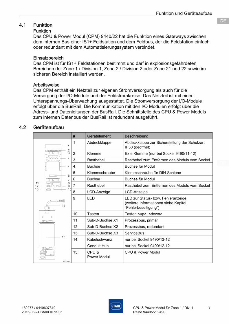
4.2 Geräteaufbau# Gerätelement Beschreibung
12223E00
1 Abdeckklappe Abdeckklappe zur Sicherstellung der Schutzart IP30 (geöffnet)
2 Klemme Ex e Klemme (nur bei Sockel 9490/11-12)3 Rasthebel Rasthebel zum Entfernen des Moduls vom Sockel4 Buchse Buchse für Modul5 Klemmschraube Klemmschraube für DIN-Schiene6 Buchse Buchse für Modul7 Rasthebel Rasthebel zum Entfernen des Moduls vom Sockel8 LCD-Anzeige LCD-Anzeige9 LED LED zur Status- bzw. Fehleranzeige
(weitere Informationen siehe Kapitel "Fehlerbeseitigung")
10 Tasten Tasten <up>, <down>11 Sub-D-Buchse X1 Prozessbus, primär 12 Sub-D-Buchse X2 Prozessbus, redundant 13 Sub-D-Buchse X3 ServiceBus 14 Kabelschwanz nur bei Sockel 9490/13-12
Conduit Hub nur bei Sockel 9490/12-1215 CPU &
Power ModulCPU & Power Modul
1
23
4
5
6
78
109
111213
15
14
Technische Daten
8 162277 / 94406073102016-03-24·BA00·III·de·05
CPU & Power Modul für Zone 1 / Div. 1Reihe 9440/22, 9490
DEDEDEDEDEDEDEDEDEDEDEDEDEDEDEDEDEDEDEDEDEDEDEDEDE
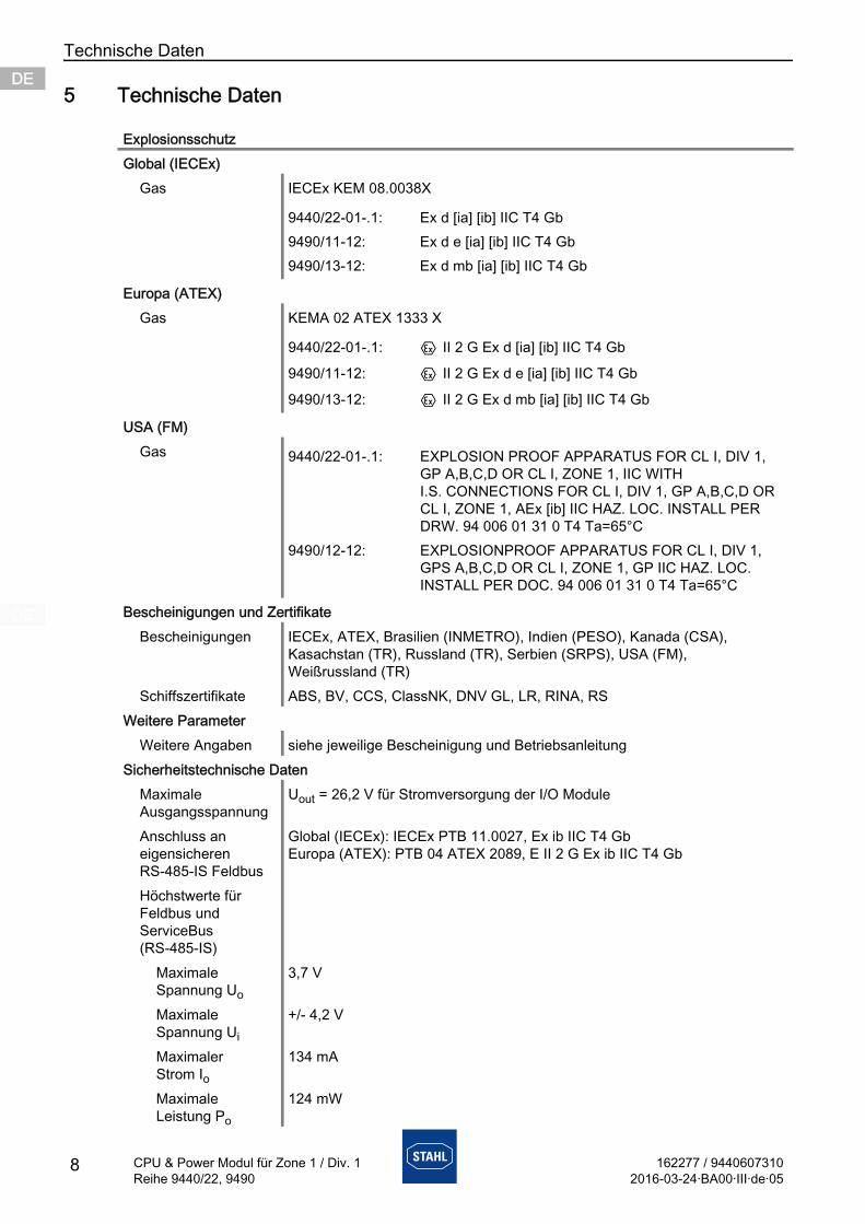
5 Technische Daten
ExplosionsschutzGlobal (IECEx)
Gas IECEx KEM 08.0038X
Europa (ATEX)Gas KEMA 02 ATEX 1333 X
USA (FM)Gas
Bescheinigungen und ZertifikateBescheinigungen IECEx, ATEX, Brasilien (INMETRO), Indien (PESO), Kanada (CSA),
Kasachstan (TR), Russland (TR), Serbien (SRPS), USA (FM), Weißrussland (TR)
Schiffszertifikate ABS, BV, CCS, ClassNK, DNV GL, LR, RINA, RSWeitere Parameter
Weitere Angaben siehe jeweilige Bescheinigung und BetriebsanleitungSicherheitstechnische Daten
Maximale Ausgangsspannung
Uout = 26,2 V für Stromversorgung der I/O Module
Anschluss an eigensicheren RS-485-IS Feldbus
Global (IECEx): IECEx PTB 11.0027, Ex ib IIC T4 GbEuropa (ATEX): PTB 04 ATEX 2089, E II 2 G Ex ib IIC T4 Gb
Höchstwerte für Feldbus und ServiceBus (RS-485-IS)
Maximale Spannung Uo
3,7 V
Maximale Spannung Ui
+/- 4,2 V
Maximaler Strom Io
134 mA
Maximale Leistung Po
124 mW
9440/22-01-.1: Ex d [ia] [ib] IIC T4 Gb9490/11-12: Ex d e [ia] [ib] IIC T4 Gb9490/13-12: Ex d mb [ia] [ib] IIC T4 Gb
9440/22-01-.1: E II 2 G Ex d [ia] [ib] IIC T4 Gb
9490/11-12: E II 2 G Ex d e [ia] [ib] IIC T4 Gb
9490/13-12: E II 2 G Ex d mb [ia] [ib] IIC T4 Gb
9440/22-01-.1: EXPLOSION PROOF APPARATUS FOR CL I, DIV 1, GP A,B,C,D OR CL I, ZONE 1, IIC WITH I.S. CONNECTIONS FOR CL I, DIV 1, GP A,B,C,D OR CL I, ZONE 1, AEx [ib] IIC HAZ. LOC. INSTALL PER DRW. 94 006 01 31 0 T4 Ta=65°C
9490/12-12: EXPLOSIONPROOF APPARATUS FOR CL I, DIV 1, GPS A,B,C,D OR CL I, ZONE 1, GP IIC HAZ. LOC. INSTALL PER DOC. 94 006 01 31 0 T4 Ta=65°C
162277 / 94406073102016-03-24·BA00·III·de·05
Technische Daten
9
DEDEDEDEDEDEDEDEDEDEDEDEDEDEDEDEDEDEDEDEDEDEDEDEDE
CPU & Power Modul für Zone 1 / Div. 1Reihe 9440/22, 9490
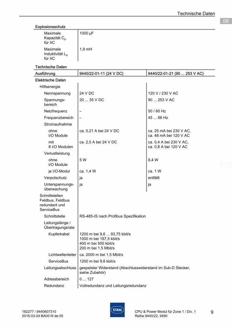
Maximale Kapazität Co für IIC
1000 mF
Maximale Induktivität Lo für IIC
1,9 mH
Technische DatenAusführung 9440/22-01-11 (24 V DC) 9440/22-01-21 (90 ... 253 V AC)Elektrische Daten
HilfsenergieNennspannung 24 V DC 120 V / 230 V ACSpannungs- bereich
20 ... 35 V DC 90 ... 253 V AC
Netzfrequenz – 50 / 60 HzFrequenzbereich – 45 ... 66 HzStromaufnahme
ohne I/O Module
ca. 0,21 A bei 24 V DC ca. 25 mA bei 230 V AC,ca. 48 mA bei 120 V AC
mit 8 I/O Modulen
ca. 2,5 A bei 24 V DC ca. 0,4 A bei 230 V AC,ca. 0,8 A bei 120 V AC
Verlustleistungohne I/O Module
5 W 8,4 W
je I/O-Modul ca. 1,4 W ca. 1 WVerpolschutz ja entfälltUnterspannungs- überwachung
ja ja
Schnittstellen Feldbus, Feldbus redundant und ServiceBus
Schnittstelle RS-485-IS nach Profibus SpezifikationLeitungslänge / Übertragungsrate
Kupferkabel 1200 m bei 9,6 ... 93,75 kbit/s1000 m bei 187,5 kbit/s400 m bei 500 kbit/s200 m bei 1,5 Mbit/s
Lichtwellenleiter ca. 2000 m bei 1,5 Mbit/sServiceBus 1200 m bei 9,6 kbit/s
Leitungsabschluss gespeister Widerstand (Abschlusswiderstand im Sub-D Stecker, siehe Zubehör)
Adressbereich 0 ... 127Redundanz Vollredundanz und Leitungsredundanz
Explosionsschutz

Technische Daten
10 162277 / 94406073102016-03-24·BA00·III·de·05
CPU & Power Modul für Zone 1 / Div. 1Reihe 9440/22, 9490
DEDEDEDEDEDEDEDEDEDEDEDEDEDEDEDEDEDEDEDEDEDEDEDEDE
ProfibusVersionen DP V0, DP V1, DP V1 HARTÜbertragungs- geschwindigkeit
9,6 kbit/s ... 1,5 Mbit/s
Datenübertragung ca. 40 16-Bit-Worte / ms (zyklisch, netto bei 1,5 Mbit/s)Modbus RTU
Übertragungs- geschwindigkeit
9,6 ... 38,4 kbit/s
Datenübertragung ca. 1000 16-Bit-Register / s (bei 38,4 kbit/s)Funktionen Read, Write; siehe Kopplungsbeschreibung Modbus RTU
KennwerteMax. interne Signalver- zögerung bei 8 I/O Modulen (ohne Modul- verzögerung)
für Digital-Module
7 ms
für Analog-Module
10 ms
Bediener- Schnittstelle
Software IS1 Geräte DTM oder IS WizardBetrieb LED grün "RUN"Fehler LED rot "ERR"LCD-Anzeige 2 x 16 ZeichenEinstellungen BusadresseAnzeigen Busadresse, Alarme / Fehler, Informationen (Typ, Revision usw.) für die
Ebenen Feldstation, Module und Signale, Werte der Eingänge und AusgängeDiagnose und Parametrierung
Funktionen • Konfigurationsdaten und Parameter in IS1-Feldstationen laden oder rücklesen
• Eingänge lesen• Ausgänge lesen und schreiben• Diagnosedaten übertragen (z.B. Konfig-Fehler, Hardware-Fehler,
Signal-Fehler)• HART-Kommandos von / zu HART-Feldgeräten übertragen
Anschließbare Softwarepakete
• IS Wizard (über R. STAHL ServiceBus)• R. STAHL DTM• AMS von Emerson Process Management• PDM von Siemens• PRM und Fieldmate von Yokogawa• FieldCare von Endress + Hauser• FDM von Honeywell• etc.
Technische Daten
162277 / 94406073102016-03-24·BA00·III·de·05
Technische Daten
11
DEDEDEDEDEDEDEDEDEDEDEDEDEDEDEDEDEDEDEDEDEDEDEDEDE
CPU & Power Modul für Zone 1 / Div. 1Reihe 9440/22, 9490
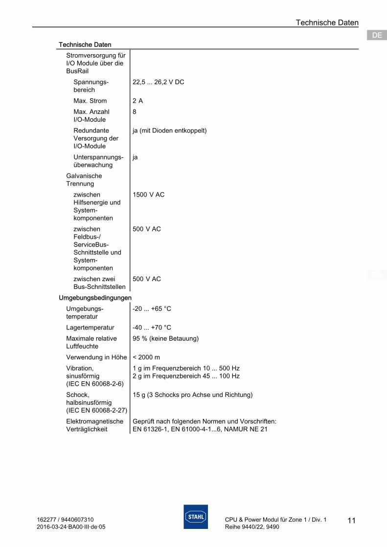
Stromversorgung für I/O Module über die BusRail
Spannungs- bereich
22,5 ... 26,2 V DC
Max. Strom 2 A Max. Anzahl I/O-Module
8
Redundante Versorgung der I/O-Module
ja (mit Dioden entkoppelt)
Unterspannungs- überwachung
ja
Galvanische Trennung
zwischen Hilfsenergie und System- komponenten
1500 V AC
zwischen Feldbus-/ ServiceBus-Schnittstelle und System- komponenten
500 V AC
zwischen zwei Bus-Schnittstellen
500 V AC
UmgebungsbedingungenUmgebungs- temperatur
-20 ... +65 °C
Lagertemperatur -40 ... +70 °CMaximale relative Luftfeuchte
95 % (keine Betauung)
Verwendung in Höhe < 2000 mVibration, sinusförmig (IEC EN 60068-2-6)
1 g im Frequenzbereich 10 ... 500 Hz2 g im Frequenzbereich 45 ... 100 Hz
Schock, halbsinusförmig (IEC EN 60068-2-27)
15 g (3 Schocks pro Achse und Richtung)
Elektromagnetische Verträglichkeit
Geprüft nach folgenden Normen und Vorschriften: EN 61326-1, EN 61000-4-1...6, NAMUR NE 21
Technische Daten
Technische Daten
12 162277 / 94406073102016-03-24·BA00·III·de·05
CPU & Power Modul für Zone 1 / Div. 1Reihe 9440/22, 9490
DEDEDEDEDEDEDEDEDEDEDEDEDEDEDEDEDEDEDEDEDEDEDEDEDE
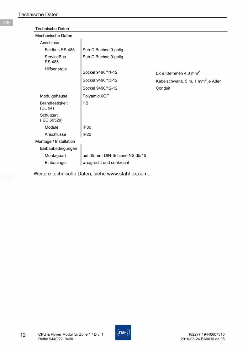
Weitere technische Daten, siehe www.stahl-ex.com.
Mechanische DatenAnschluss
Feldbus RS 485 Sub-D Buchse 9-poligServiceBus RS 485
Sub-D Buchse 9-polig
Hilfsenergie
Modulgehäuse Polyamid 6GFBrandfestigkeit (UL 94)
HB
Schutzart (IEC 60529)
Module IP30Anschlüsse IP20
Montage / InstallationEinbaubedingungen
Montageart auf 35-mm-DIN-Schiene NS 35/15Einbaulage waagrecht und senkrecht
Technische Daten
Sockel 9490/11-12 Ex e Klemmen 4,0 mm2
Sockel 9490/13-12 Kabelschwanz, 5 m, 1 mm2 je AderSockel 9490/12-12 Conduit
162277 / 94406073102016-03-24·BA00·III·de·05
Projektierung
13
DEDEDEDEDEDEDEDEDEDEDEDEDEDEDEDEDEDEDEDEDEDEDEDEDE
CPU & Power Modul für Zone 1 / Div. 1Reihe 9440/22, 9490
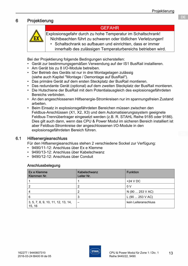
6 Projektierung
Bei der Projektierung folgende Bedingungen sicherstellen:• Gerät zur bestimmungsgemäßen Verwendung auf der IS1 BusRail installieren.• Am Gerät bis zu 8 I/O-Module betreiben.• Der Betrieb des Geräts ist nur in drei Montagelagen zulässig
(siehe auch Kapitel "Montage / Demontage auf BusRail").• Das primäre Gerät auf dem ersten Steckplatz der BusRail montieren.• Das redundante Gerät (optional) auf dem zweiten Steckplatz der BusRail montieren.• Die Hutschiene der BusRail mit dem Potentialausgleich des explosionsgefährdeten
Bereichs verbinden.• An den angeschlossenen Hilfsenergie-Stromkreisen nur im spannungsfreien Zustand
arbeiten.• Beim Einsatz in explosionsgefährdeten Bereichen müssen zwischen den
Feldbus-Anschlüssen (X1, X2, X3) und dem Automatisierungssystem geeignete Feldbus-Trennübertrager eingesetzt werden (z.B. R. STAHL Reihe 9185 oder 9186). Dies gilt auch dann, wenn das CPU & Power Modul im sicheren Bereich installiert ist aber Feldbus-Stromkreise der angeschlossenen I/O-Module in den explosionsgefährdeten Bereich führen.
6.1 HilfsenergieanschlussFür den Hilfsenergieanschluss stehen 2 verschiedene Sockel zur Verfügung:• 9490/11-12: Anschluss über Ex e Klemme• 9490/13-12: Anschluss über Kabelschwanz• 9490/12-12: Anschluss über Conduit
Anschlussbelegung
GEFAHRExplosionsgefahr durch zu hohe Temperatur im Schaltschrank!
Nichtbeachten führt zu schweren oder tödlichen Verletzungen!• Schaltschrank so aufbauen und einrichten, dass er immer
innerhalb des zulässigen Temperaturbereichs betrieben wird.
Ex e KlemmeKlemmen Nr.
KabelschwanzLeiter Nr.
Funktion
1 1 +24 V DC2 2 0 V4 2 N (90 ... 253 V AC)6 3 L (90 ... 253 V AC)3, 5, 7, 8, 9, 10, 11, 12, 13, 14, 15, 16
– kein Leiteranschluss
Transport und Lagerung
14 162277 / 94406073102016-03-24·BA00·III·de·05
CPU & Power Modul für Zone 1 / Div. 1Reihe 9440/22, 9490
DEDEDEDEDEDEDEDEDEDEDEDEDEDEDEDEDEDEDEDEDEDEDEDEDE
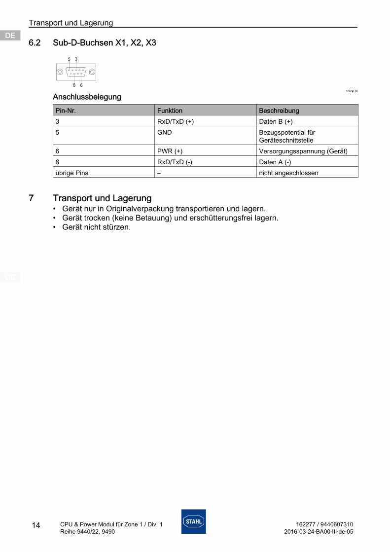
6.2 Sub-D-Buchsen X1, X2, X3
12224E00
Anschlussbelegung
7 Transport und Lagerung• Gerät nur in Originalverpackung transportieren und lagern.• Gerät trocken (keine Betauung) und erschütterungsfrei lagern.• Gerät nicht stürzen.
Pin-Nr. Funktion Beschreibung3 RxD/TxD (+) Daten B (+)5 GND Bezugspotential für
Geräteschnittstelle6 PWR (+) Versorgungsspannung (Gerät)8 RxD/TxD (-) Daten A (-)übrige Pins – nicht angeschlossen
5 3
8 6
162277 / 94406073102016-03-24·BA00·III·de·05
Montage und Installation
15
DEDEDEDEDEDEDEDEDEDEDEDEDEDEDEDEDEDEDEDEDEDEDEDEDE
CPU & Power Modul für Zone 1 / Div. 1Reihe 9440/22, 9490
8 Montage und InstallationDas Gerät ist für den Einsatz in gasexplosionsgefährdeten Bereichen der Zonen 1/ Division 1 und Zone 2/Division 2, in staubexplosionsgefährdeten Bereichen der Zonen 21 und 22 sowie auch im sicheren Bereich zugelassen.
GEFAHRExplosionsgefahr bei Installation ohne zugelassenes Feldgehäuse!
Nichtbeachten führt zu schweren oder tödlichen Verletzungen!• Bei Einsatz in Zone 1 ist das Gerät in ein Gehäuse einzubauen,
das die Anforderungen der IEC/EN 60079-11 und IEC/EN 60079-7erfüllt.
• Bei Einsatz in Zone 2 ist das Gerät in ein Gehäuse einzubauen, das die Anforderungen der IEC/EN 60079-15 erfüllt.
• Bei Einsatz in Zone 21 und 22 ist das Gerät in ein Gehäuse einzubauen, das den Anforderungen der IEC/EN 60079-31 erfüllt.
GEFAHRExplosionsgefahr durch falsche Installation des Geräts!
Nichtbeachten führt zu schweren oder tödlichen Verletzungen.• Installation strikt nach Anleitung und unter Berücksichtigung der
nationalen Sicherheits- und Unfallverhütungsvorschriften durchführen, damit der Explosionsschutz erhalten bleibt.
• Das elektrische Gerät so auswählen bzw. installieren, dass der Explosionsschutz aufgrund äußerer Einflüsse nicht beeinträchtigt wird, z.B. Druckbedingungen, chemische, mechanische, thermische, elektrische Einflüsse sowie Schwingungen, Feuchte, Korrosion (siehe IEC/EN 60079-14).
• Gerät nur durch geschultes und mit den einschlägigen Normen vertrautes Fachpersonal installieren lassen.
Montage und Installation
16 162277 / 94406073102016-03-24·BA00·III·de·05
CPU & Power Modul für Zone 1 / Div. 1Reihe 9440/22, 9490
DEDEDEDEDEDEDEDEDEDEDEDEDEDEDEDEDEDEDEDEDEDEDEDEDE
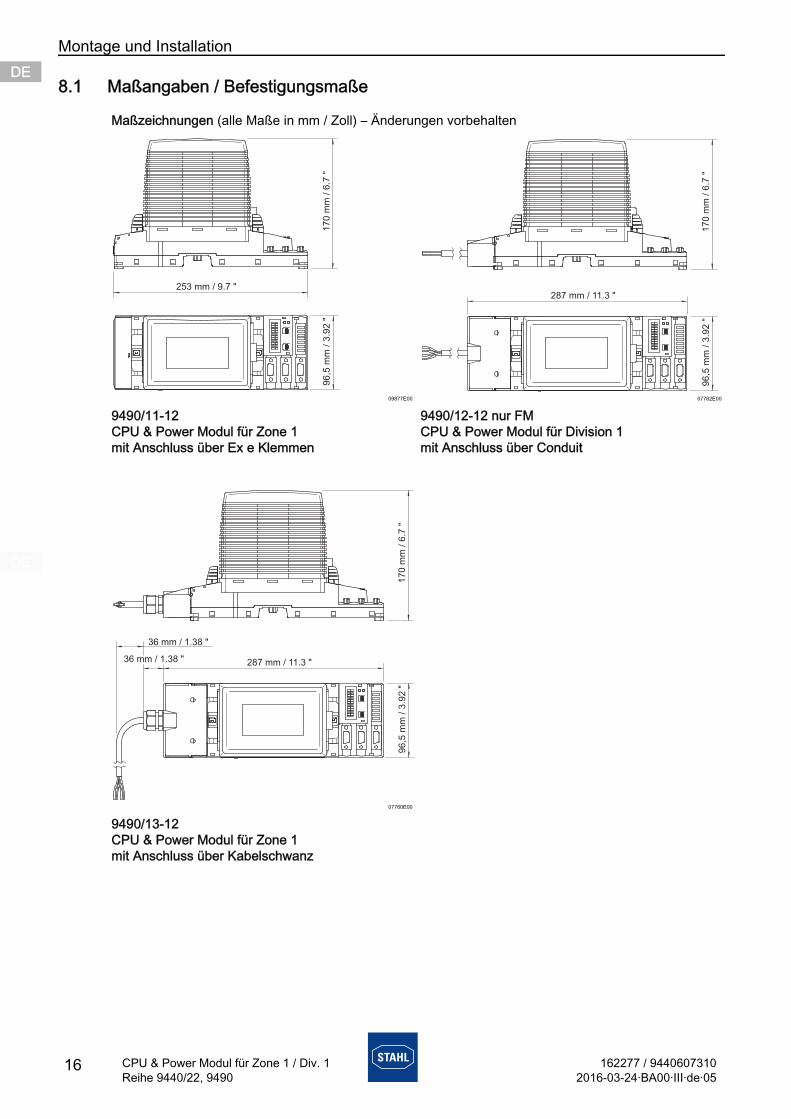
8.1 Maßangaben / Befestigungsmaße
Maßzeichnungen (alle Maße in mm / Zoll) – Änderungen vorbehalten
09877E00 07762E00
9490/11-12CPU & Power Modul für Zone 1 mit Anschluss über Ex e Klemmen
9490/12-12 nur FMCPU & Power Modul für Division 1 mit Anschluss über Conduit
07760E00
9490/13-12CPU & Power Modul für Zone 1 mit Anschluss über Kabelschwanz
287 mm / 11.3 "
96
,5 m
m /
3.9
2 "
17
0 m
m /
6.7
"
162277 / 94406073102016-03-24·BA00·III·de·05
Montage und Installation
17
DEDEDEDEDEDEDEDEDEDEDEDEDEDEDEDEDEDEDEDEDEDEDEDEDE
CPU & Power Modul für Zone 1 / Div. 1Reihe 9440/22, 9490
8.2 Montage / Demontage, Gebrauchslage
8.2.1 Montage / Demontage auf BusRail
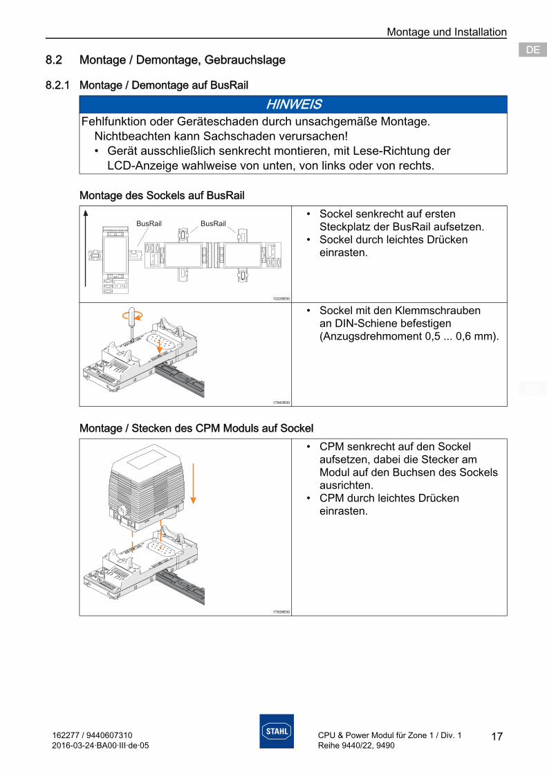
Montage des Sockels auf BusRail
Montage / Stecken des CPM Moduls auf Sockel
HINWEISFehlfunktion oder Geräteschaden durch unsachgemäße Montage.
Nichtbeachten kann Sachschaden verursachen!• Gerät ausschließlich senkrecht montieren, mit Lese-Richtung der
LCD-Anzeige wahlweise von unten, von links oder von rechts.
12225E00
• Sockel senkrecht auf ersten Steckplatz der BusRail aufsetzen.
• Sockel durch leichtes Drücken einrasten.
17942E00
• Sockel mit den Klemmschrauben an DIN-Schiene befestigen (Anzugsdrehmoment 0,5 ... 0,6 mm).
17939E00
• CPM senkrecht auf den Sockel aufsetzen, dabei die Stecker am Modul auf den Buchsen des Sockels ausrichten.
• CPM durch leichtes Drücken einrasten.
BusRailBusRail
Montage und Installation
18 162277 / 94406073102016-03-24·BA00·III·de·05
CPU & Power Modul für Zone 1 / Div. 1Reihe 9440/22, 9490
DEDEDEDEDEDEDEDEDEDEDEDEDEDEDEDEDEDEDEDEDEDEDEDEDE
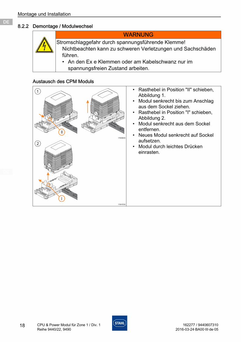
8.2.2 Demontage / Modulwechsel
Austausch des CPM Moduls
WARNUNGStromschlaggefahr durch spannungsführende Klemme!
Nichtbeachten kann zu schweren Verletzungen und Sachschäden führen.• An den Ex e Klemmen oder am Kabelschwanz nur im
spannungsfreien Zustand arbeiten.
17940E00
17941E00
• Rasthebel in Position "II" schieben, Abbildung 1.
• Modul senkrecht bis zum Anschlag aus dem Sockel ziehen.
• Rasthebel in Position "I" schieben, Abbildung 2.
• Modul senkrecht aus dem Sockel entfernen.
• Neues Modul senkrecht auf Sockel aufsetzen.
• Modul durch leichtes Drücken einrasten.
162277 / 94406073102016-03-24·BA00·III·de·05
Montage und Installation
19
DEDEDEDEDEDEDEDEDEDEDEDEDEDEDEDEDEDEDEDEDEDEDEDEDE
CPU & Power Modul für Zone 1 / Div. 1Reihe 9440/22, 9490
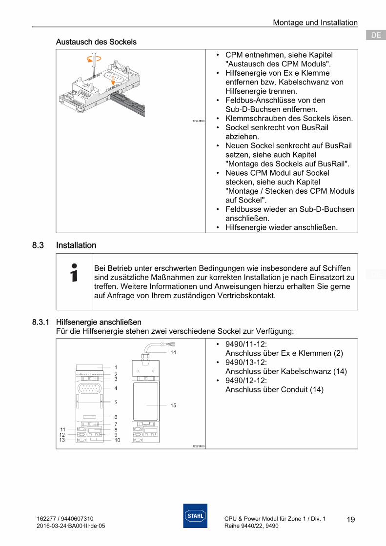
Austausch des Sockels
8.3 Installation
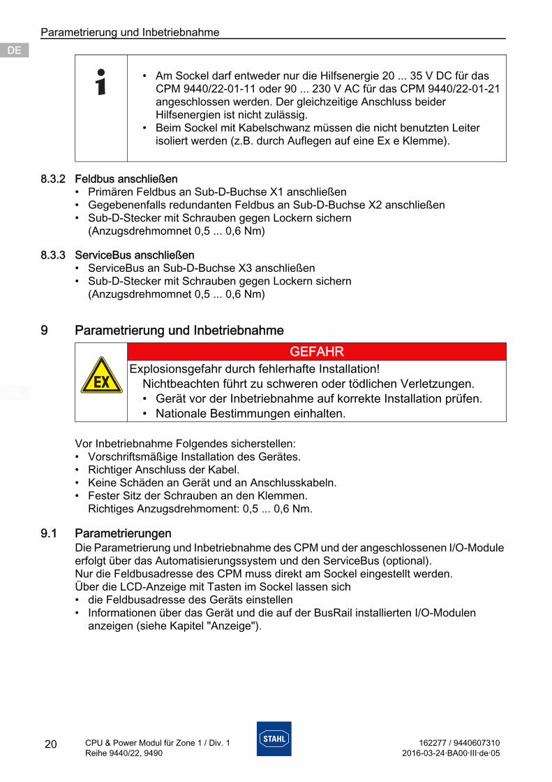
8.3.1 Hilfsenergie anschließenFür die Hilfsenergie stehen zwei verschiedene Sockel zur Verfügung:
17943E00
• CPM entnehmen, siehe Kapitel "Austausch des CPM Moduls".
• Hilfsenergie von Ex e Klemme entfernen bzw. Kabelschwanz von Hilfsenergie trennen.
• Feldbus-Anschlüsse von den Sub-D-Buchsen entfernen.
• Klemmschrauben des Sockels lösen.• Sockel senkrecht von BusRail
abziehen.• Neuen Sockel senkrecht auf BusRail
setzen, siehe auch Kapitel "Montage des Sockels auf BusRail".
• Neues CPM Modul auf Sockel stecken, siehe auch Kapitel "Montage / Stecken des CPM Moduls auf Sockel".
• Feldbusse wieder an Sub-D-Buchsen anschließen.
• Hilfsenergie wieder anschließen.
Bei Betrieb unter erschwerten Bedingungen wie insbesondere auf Schiffen sind zusätzliche Maßnahmen zur korrekten Installation je nach Einsatzort zu treffen. Weitere Informationen und Anweisungen hierzu erhalten Sie gerne auf Anfrage von Ihrem zuständigen Vertriebskontakt.
12223E00
• 9490/11-12: Anschluss über Ex e Klemmen (2)
• 9490/13-12: Anschluss über Kabelschwanz (14)
• 9490/12-12: Anschluss über Conduit (14)
15
1
23
4
5
6
78
109
111213
14
Parametrierung und Inbetriebnahme
20 162277 / 94406073102016-03-24·BA00·III·de·05
CPU & Power Modul für Zone 1 / Div. 1Reihe 9440/22, 9490
DEDEDEDEDEDEDEDEDEDEDEDEDEDEDEDEDEDEDEDEDEDEDEDEDE
8.3.2 Feldbus anschließen• Primären Feldbus an Sub-D-Buchse X1 anschließen• Gegebenenfalls redundanten Feldbus an Sub-D-Buchse X2 anschließen• Sub-D-Stecker mit Schrauben gegen Lockern sichern
(Anzugsdrehmomnet 0,5 ... 0,6 Nm)
8.3.3 ServiceBus anschließen• ServiceBus an Sub-D-Buchse X3 anschließen• Sub-D-Stecker mit Schrauben gegen Lockern sichern
(Anzugsdrehmomnet 0,5 ... 0,6 Nm)
9 Parametrierung und Inbetriebnahme
Vor Inbetriebnahme Folgendes sicherstellen:• Vorschriftsmäßige Installation des Gerätes.• Richtiger Anschluss der Kabel.• Keine Schäden an Gerät und an Anschlusskabeln.• Fester Sitz der Schrauben an den Klemmen.
Richtiges Anzugsdrehmoment: 0,5 ... 0,6 Nm.
9.1 ParametrierungenDie Parametrierung und Inbetriebnahme des CPM und der angeschlossenen I/O-Module erfolgt über das Automatisierungssystem und den ServiceBus (optional).Nur die Feldbusadresse des CPM muss direkt am Sockel eingestellt werden.Über die LCD-Anzeige mit Tasten im Sockel lassen sich• die Feldbusadresse des Geräts einstellen• Informationen über das Gerät und die auf der BusRail installierten I/O-Modulen
anzeigen (siehe Kapitel "Anzeige").
• Am Sockel darf entweder nur die Hilfsenergie 20 ... 35 V DC für das CPM 9440/22-01-11 oder 90 ... 230 V AC für das CPM 9440/22-01-21 angeschlossen werden. Der gleichzeitige Anschluss beider Hilfsenergien ist nicht zulässig.
• Beim Sockel mit Kabelschwanz müssen die nicht benutzten Leiter isoliert werden (z.B. durch Auflegen auf eine Ex e Klemme).
GEFAHRExplosionsgefahr durch fehlerhafte Installation!
Nichtbeachten führt zu schweren oder tödlichen Verletzungen.• Gerät vor der Inbetriebnahme auf korrekte Installation prüfen.• Nationale Bestimmungen einhalten.
162277 / 94406073102016-03-24·BA00·III·de·05
Parametrierung und Inbetriebnahme
21
DEDEDEDEDEDEDEDEDEDEDEDEDEDEDEDEDEDEDEDEDEDEDEDEDE
CPU & Power Modul für Zone 1 / Div. 1Reihe 9440/22, 9490
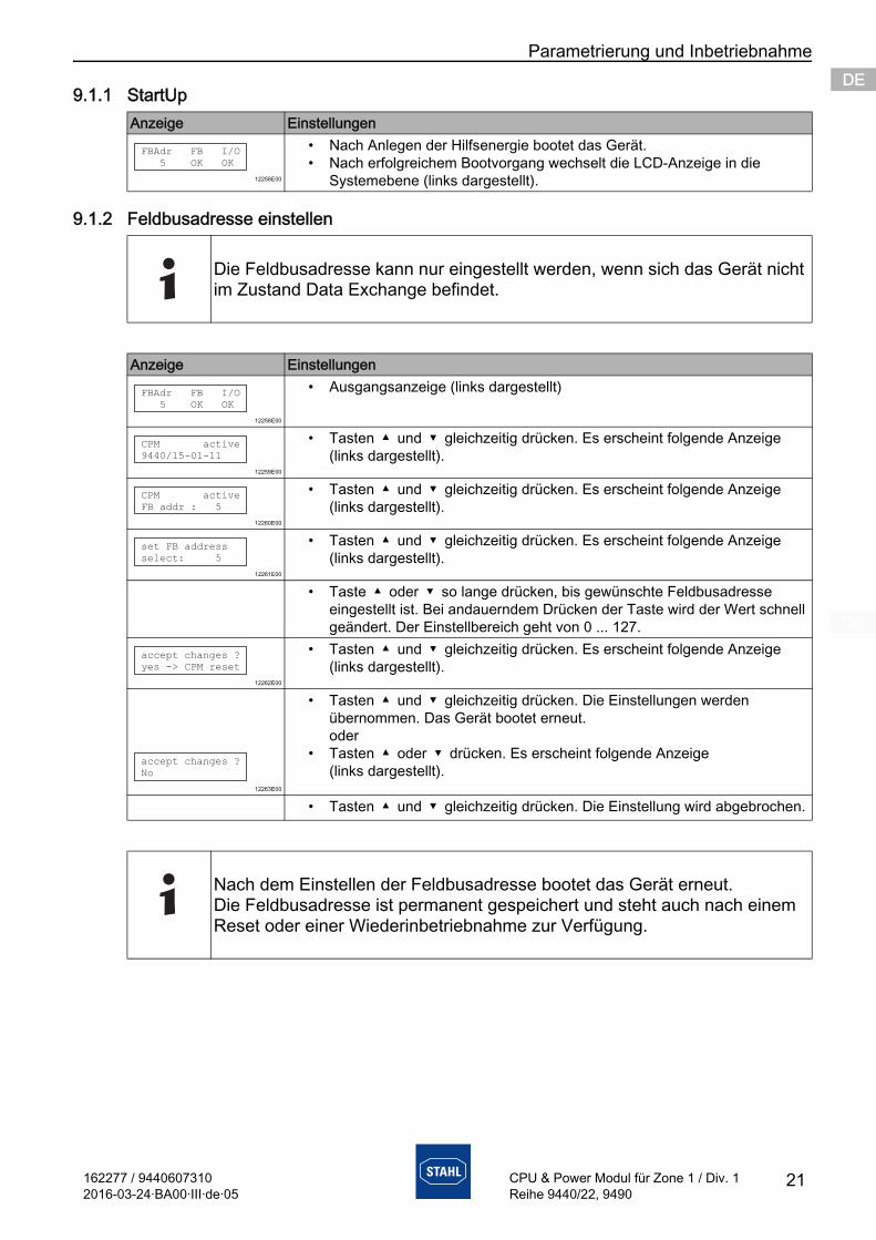
9.1.1 StartUp
9.1.2 Feldbusadresse einstellen
Anzeige Einstellungen
12258E00
• Nach Anlegen der Hilfsenergie bootet das Gerät.• Nach erfolgreichem Bootvorgang wechselt die LCD-Anzeige in die
Systemebene (links dargestellt).
Die Feldbusadresse kann nur eingestellt werden, wenn sich das Gerät nicht im Zustand Data Exchange befindet.
Anzeige Einstellungen
12258E00
• Ausgangsanzeige (links dargestellt)
12259E00
• Tasten und gleichzeitig drücken. Es erscheint folgende Anzeige (links dargestellt).
12260E00
• Tasten und gleichzeitig drücken. Es erscheint folgende Anzeige (links dargestellt).
12261E00
• Tasten und gleichzeitig drücken. Es erscheint folgende Anzeige (links dargestellt).
• Taste oder so lange drücken, bis gewünschte Feldbusadresse eingestellt ist. Bei andauerndem Drücken der Taste wird der Wert schnell geändert. Der Einstellbereich geht von 0 ... 127.
12262E00
• Tasten und gleichzeitig drücken. Es erscheint folgende Anzeige (links dargestellt).
12263E00
• Tasten und gleichzeitig drücken. Die Einstellungen werden übernommen. Das Gerät bootet erneut. oder
• Tasten oder drücken. Es erscheint folgende Anzeige (links dargestellt).
• Tasten und gleichzeitig drücken. Die Einstellung wird abgebrochen.
Nach dem Einstellen der Feldbusadresse bootet das Gerät erneut.Die Feldbusadresse ist permanent gespeichert und steht auch nach einem Reset oder einer Wiederinbetriebnahme zur Verfügung.
FBAdr FB I/O
5 OK OK
FBAdr FB I/O
5 OK OK
CPM active
9440/15-01-11
CPM active
FB addr : 5
set FB address
select: 5
accept changes ?
yes -> CPM reset
accept changes ?
No
Betrieb
22 162277 / 94406073102016-03-24·BA00·III·de·05
CPU & Power Modul für Zone 1 / Div. 1Reihe 9440/22, 9490
DEDEDEDEDEDEDEDEDEDEDEDEDEDEDEDEDEDEDEDEDEDEDEDEDE
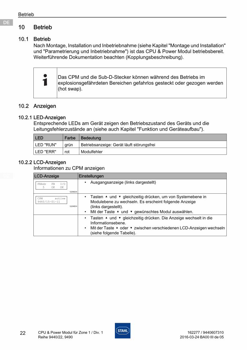
10 Betrieb
10.1 BetriebNach Montage, Installation und Inbetriebnahme (siehe Kapitel "Montage und Installation" und "Parametrierung und Inbetriebnahme") ist das CPU & Power Modul betriebsbereit.Weiterführende Dokumentation beachten (Kopplungsbeschreibung).
10.2 Anzeigen
10.2.1 LED-AnzeigenEntsprechende LEDs am Gerät zeigen den Betriebszustand des Geräts und die Leitungsfehlerzustände an (siehe auch Kapitel "Funktion und Geräteaufbau").
10.2.2 LCD-AnzeigenInformationen zu CPM anzeigen
Das CPM und die Sub-D-Stecker können während des Betriebs im explosionsgefährdeten Bereichen gefahrlos gesteckt oder gezogen werden (hot swap).
LED Farbe BedeutungLED "RUN" grün Betriebsanzeige: Gerät läuft störungsfreiLED "ERR" rot Modulfehler
LCD-Anzeige Einstellungen
12258E00
• Ausgangsanzeige (links dargestellt)
12259E00
• Tasten und gleichzeitig drücken, um von Systemebene in Modulebene zu wechseln. Es erscheint folgende Anzeige (links dargestellt).
• Mit der Taste und gewünschtes Modul auswählen.• Tasten und gleichzeitig drücken. Die Anzeige wechselt in die
Informationsebene.• Mit der Taste oder zwischen verschiedenen LCD-Anzeigen wechseln
(siehe folgende Tabelle).
FBAdr FB I/O
5 OK OK
CPM active
9440/15-01-11
162277 / 94406073102016-03-24·BA00·III·de·05
Betrieb
23
DEDEDEDEDEDEDEDEDEDEDEDEDEDEDEDEDEDEDEDEDEDEDEDEDE
CPU & Power Modul für Zone 1 / Div. 1Reihe 9440/22, 9490
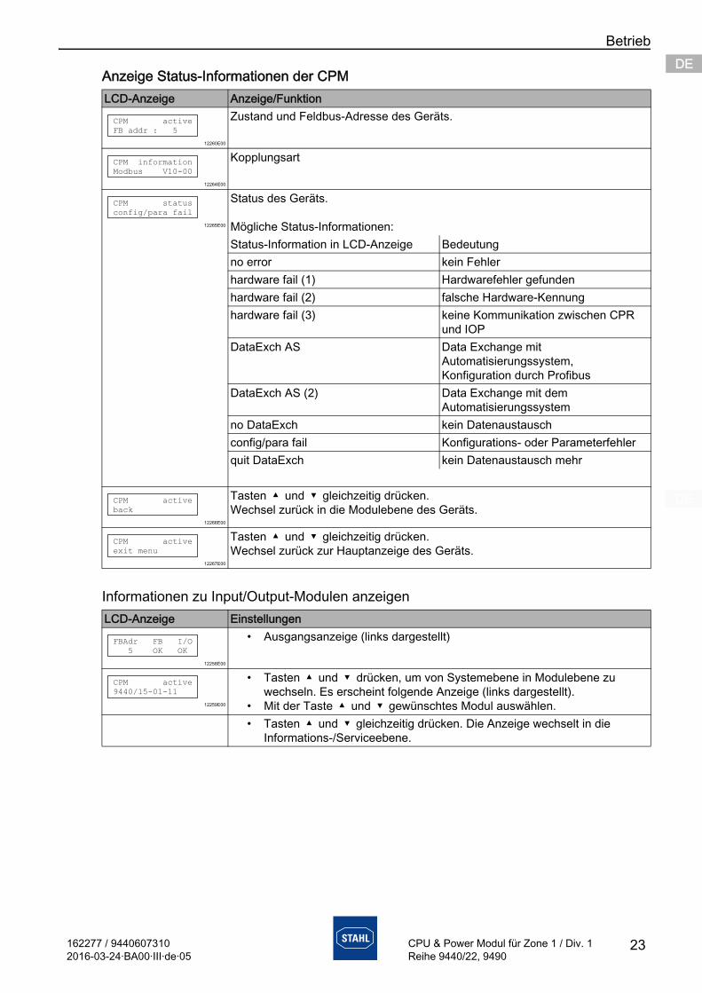
Anzeige Status-Informationen der CPM
Informationen zu Input/Output-Modulen anzeigen
LCD-Anzeige Anzeige/Funktion
12260E00
Zustand und Feldbus-Adresse des Geräts.
12264E00
Kopplungsart
12265E00
Status des Geräts.
Mögliche Status-Informationen:Status-Information in LCD-Anzeige Bedeutungno error kein Fehlerhardware fail (1) Hardwarefehler gefundenhardware fail (2) falsche Hardware-Kennunghardware fail (3) keine Kommunikation zwischen CPR
und IOPDataExch AS Data Exchange mit
Automatisierungssystem, Konfiguration durch Profibus
DataExch AS (2) Data Exchange mit dem Automatisierungssystem
no DataExch kein Datenaustauschconfig/para fail Konfigurations- oder Parameterfehlerquit DataExch kein Datenaustausch mehr
12266E00
Tasten und gleichzeitig drücken. Wechsel zurück in die Modulebene des Geräts.
12267E00
Tasten und gleichzeitig drücken. Wechsel zurück zur Hauptanzeige des Geräts.
LCD-Anzeige Einstellungen
12258E00
• Ausgangsanzeige (links dargestellt)
12259E00
• Tasten und drücken, um von Systemebene in Modulebene zu wechseln. Es erscheint folgende Anzeige (links dargestellt).
• Mit der Taste und gewünschtes Modul auswählen.• Tasten und gleichzeitig drücken. Die Anzeige wechselt in die
Informations-/Serviceebene.
CPM active
FB addr : 5
CPM information
Modbus V10-00
CPM status
config/para fail
CPM active
back
CPM active
exit menu
FBAdr FB I/O
5 OK OK
CPM active
9440/15-01-11
Betrieb
24 162277 / 94406073102016-03-24·BA00·III·de·05
CPU & Power Modul für Zone 1 / Div. 1Reihe 9440/22, 9490
DEDEDEDEDEDEDEDEDEDEDEDEDEDEDEDEDEDEDEDEDEDEDEDEDE
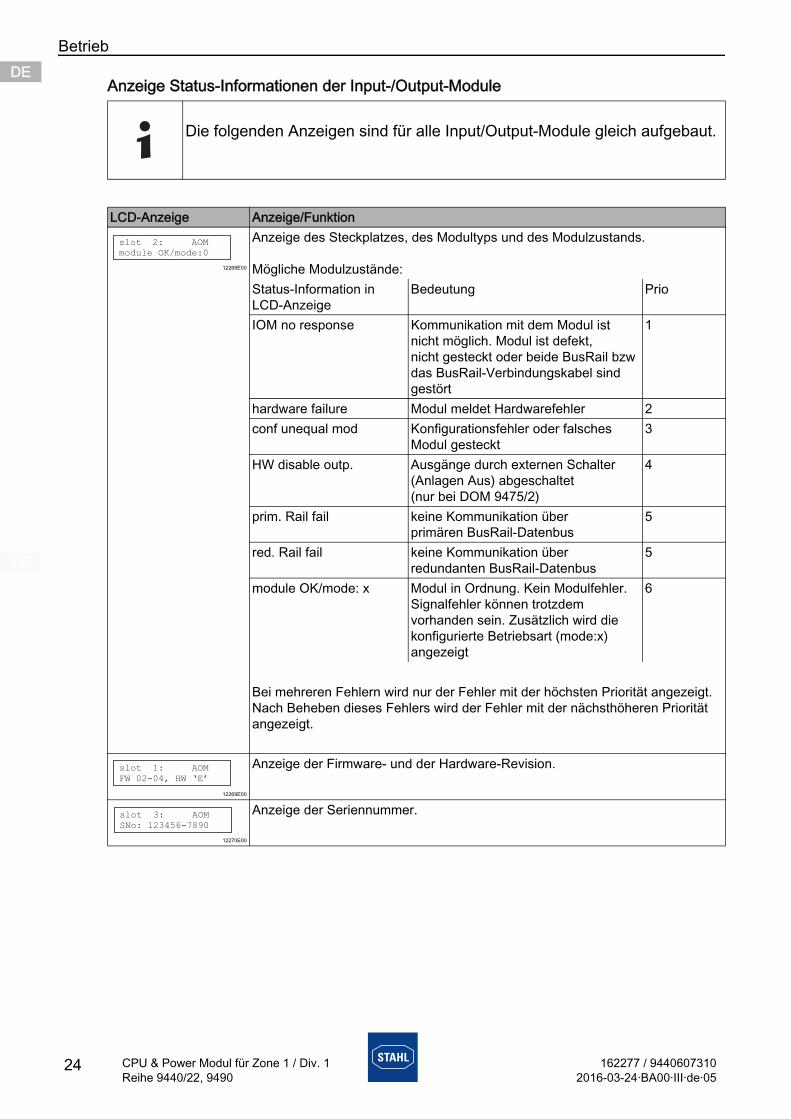
Anzeige Status-Informationen der Input-/Output-Module
Die folgenden Anzeigen sind für alle Input/Output-Module gleich aufgebaut.
LCD-Anzeige Anzeige/Funktion
12268E00
Anzeige des Steckplatzes, des Modultyps und des Modulzustands.
Mögliche Modulzustände:Status-Information in LCD-Anzeige
Bedeutung Prio
IOM no response Kommunikation mit dem Modul ist nicht möglich. Modul ist defekt, nicht gesteckt oder beide BusRail bzw das BusRail-Verbindungskabel sind gestört
1
hardware failure Modul meldet Hardwarefehler 2conf unequal mod Konfigurationsfehler oder falsches
Modul gesteckt3
HW disable outp. Ausgänge durch externen Schalter (Anlagen Aus) abgeschaltet (nur bei DOM 9475/2)
4
prim. Rail fail keine Kommunikation über primären BusRail-Datenbus
5
red. Rail fail keine Kommunikation über redundanten BusRail-Datenbus
5
module OK/mode: x Modul in Ordnung. Kein Modulfehler. Signalfehler können trotzdem vorhanden sein. Zusätzlich wird die konfigurierte Betriebsart (mode:x) angezeigt
6
Bei mehreren Fehlern wird nur der Fehler mit der höchsten Priorität angezeigt. Nach Beheben dieses Fehlers wird der Fehler mit der nächsthöheren Priorität angezeigt.
12269E00
Anzeige der Firmware- und der Hardware-Revision.
12270E00
Anzeige der Seriennummer.
slot 2: AOM
module OK/mode:0
slot 1: AOM
FW 02-04, HW ‘E’
slot 3: AOM
SNo: 123456-7890
162277 / 94406073102016-03-24·BA00·III·de·05
Betrieb
25
DEDEDEDEDEDEDEDEDEDEDEDEDEDEDEDEDEDEDEDEDEDEDEDEDE
CPU & Power Modul für Zone 1 / Div. 1Reihe 9440/22, 9490
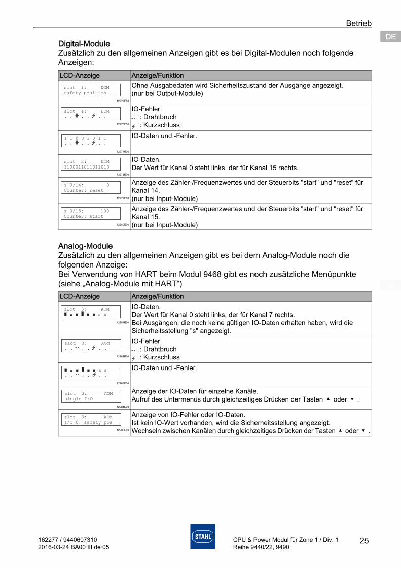
Digital-ModuleZusätzlich zu den allgemeinen Anzeigen gibt es bei Digital-Modulen noch folgende Anzeigen:
Analog-ModuleZusätzlich zu den allgemeinen Anzeigen gibt es bei dem Analog-Module noch die folgenden Anzeige:Bei Verwendung von HART beim Modul 9468 gibt es noch zusätzliche Menüpunkte (siehe „Analog-Module mit HART“)
LCD-Anzeige Anzeige/Funktion
12272E00
Ohne Ausgabedaten wird Sicherheitszustand der Ausgänge angezeigt.(nur bei Output-Module)
12273E00
IO-Fehler.: Drahtbruch: Kurzschluss
12274E00
IO-Daten und -Fehler.
12276E00
IO-Daten.Der Wert für Kanal 0 steht links, der für Kanal 15 rechts.
12279E00
Anzeige des Zähler-/Frequenzwertes und der Steuerbits "start" und "reset" für Kanal 14.(nur bei Input-Module)
12280E00
Anzeige des Zähler-/Frequenzwertes und der Steuerbits "start" und "reset" für Kanal 15.(nur bei Input-Module)
LCD-Anzeige Anzeige/Funktion
12281E00
IO-Daten.Der Wert für Kanal 0 steht links, der für Kanal 7 rechts.Bei Ausgängen, die noch keine gültigen IO-Daten erhalten haben, wird die Sicherheitsstellung "s" angezeigt.
12282E00
IO-Fehler.: Drahtbruch: Kurzschluss
12283E00
IO-Daten und -Fehler.
12284E00
Anzeige der IO-Daten für einzelne Kanäle.Aufruf des Untermenüs durch gleichzeitiges Drücken der Tasten oder .
12285E00
Anzeige von IO-Fehler oder IO-Daten.Ist kein IO-Wert vorhanden, wird die Sicherheitsstellung angezeigt.Wechseln zwischen Kanälen durch gleichzeitiges Drücken der Tasten oder .
slot 1: DOM
safety position
slot 1: DOM
. . . . . .
1 1 0 0 1 0 1 1
. . . . . .
slot 2: DIM
1100011011011010
s 3/14: 0
Counter: reset
s 3/15: 100
Counter: start
slot 3: AOM
s s
slot 3: AOM
. . . . . .
s s
. . . . . .
slot 3: AOM
single I/O
slot 3: AOM
I/O 0: safety pos
Betrieb
26 162277 / 94406073102016-03-24·BA00·III·de·05
CPU & Power Modul für Zone 1 / Div. 1Reihe 9440/22, 9490
DEDEDEDEDEDEDEDEDEDEDEDEDEDEDEDEDEDEDEDEDEDEDEDEDE
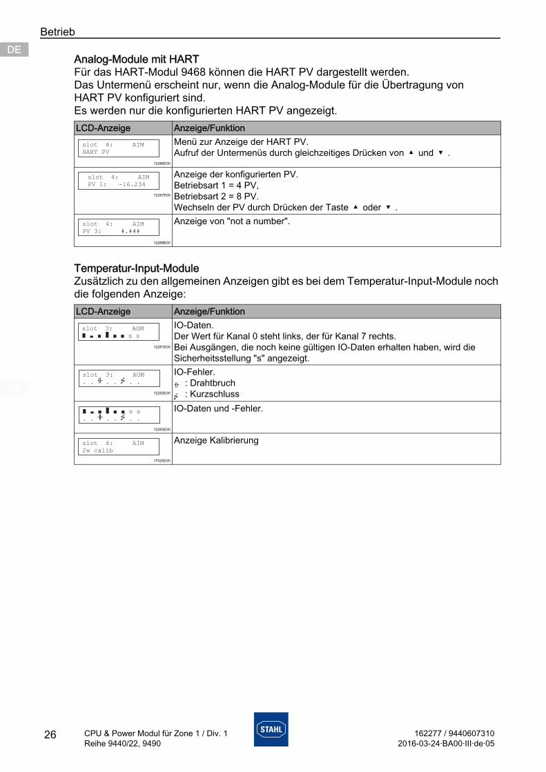
Analog-Module mit HARTFür das HART-Modul 9468 können die HART PV dargestellt werden.Das Untermenü erscheint nur, wenn die Analog-Module für die Übertragung von HART PV konfiguriert sind.Es werden nur die konfigurierten HART PV angezeigt.
Temperatur-Input-ModuleZusätzlich zu den allgemeinen Anzeigen gibt es bei dem Temperatur-Input-Module noch die folgenden Anzeige:
LCD-Anzeige Anzeige/Funktion
12286E00
Menü zur Anzeige der HART PV.Aufruf der Untermenüs durch gleichzeitiges Drücken von und .
12287E00
Anzeige der konfigurierten PV.Betriebsart 1 = 4 PV,Betriebsart 2 = 8 PV.Wechseln der PV durch Drücken der Taste oder .
12288E00
Anzeige von "not a number".
LCD-Anzeige Anzeige/Funktion
12281E00
IO-Daten.Der Wert für Kanal 0 steht links, der für Kanal 7 rechts.Bei Ausgängen, die noch keine gültigen IO-Daten erhalten haben, wird die Sicherheitsstellung "s" angezeigt.
12282E00
IO-Fehler.: Drahtbruch: Kurzschluss
12283E00
IO-Daten und -Fehler.
17025E00
Anzeige Kalibrierung
slot 4: AIM
HART PV
slot 4: AIM
PV 1: -16.234
slot 4: AIM
PV 3: #.###
slot 3: AOM
s s
slot 3: AOM
. . . . . .
s s
. . . . . .
slot 4: AIM
2w calib
162277 / 94406073102016-03-24·BA00·III·de·05
Betrieb
27
DEDEDEDEDEDEDEDEDEDEDEDEDEDEDEDEDEDEDEDEDEDEDEDEDE
CPU & Power Modul für Zone 1 / Div. 1Reihe 9440/22, 9490
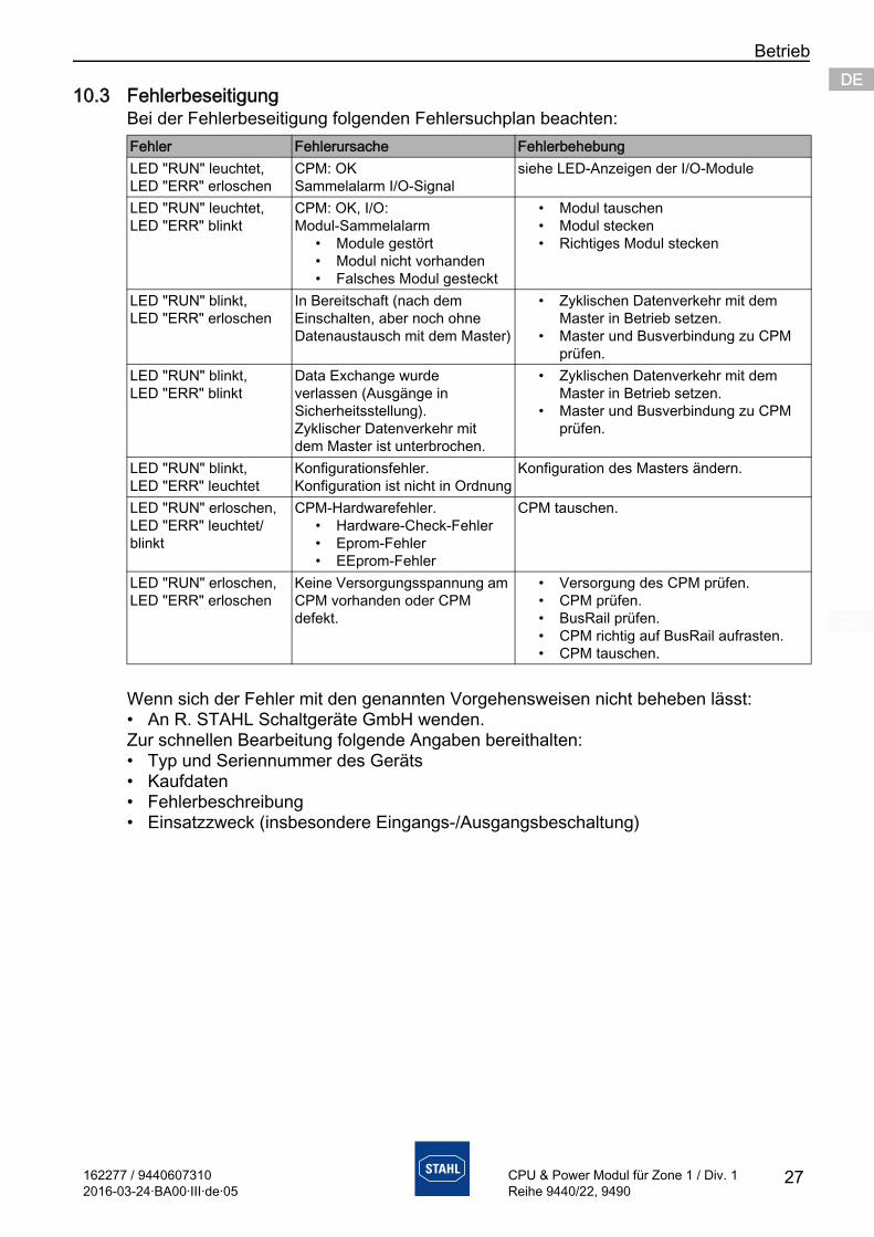
10.3 FehlerbeseitigungBei der Fehlerbeseitigung folgenden Fehlersuchplan beachten:
Wenn sich der Fehler mit den genannten Vorgehensweisen nicht beheben lässt:• An R. STAHL Schaltgeräte GmbH wenden.Zur schnellen Bearbeitung folgende Angaben bereithalten: • Typ und Seriennummer des Geräts• Kaufdaten • Fehlerbeschreibung • Einsatzzweck (insbesondere Eingangs-/Ausgangsbeschaltung)
Fehler Fehlerursache FehlerbehebungLED "RUN" leuchtet,LED "ERR" erloschen
CPM: OKSammelalarm I/O-Signal
siehe LED-Anzeigen der I/O-Module
LED "RUN" leuchtet,LED "ERR" blinkt
CPM: OK, I/O: Modul-Sammelalarm
• Module gestört• Modul nicht vorhanden• Falsches Modul gesteckt
• Modul tauschen• Modul stecken• Richtiges Modul stecken
LED "RUN" blinkt,LED "ERR" erloschen
In Bereitschaft (nach dem Einschalten, aber noch ohne Datenaustausch mit dem Master)
• Zyklischen Datenverkehr mit dem Master in Betrieb setzen.
• Master und Busverbindung zu CPM prüfen.
LED "RUN" blinkt,LED "ERR" blinkt
Data Exchange wurde verlassen (Ausgänge in Sicherheitsstellung).Zyklischer Datenverkehr mit dem Master ist unterbrochen.
• Zyklischen Datenverkehr mit dem Master in Betrieb setzen.
• Master und Busverbindung zu CPM prüfen.
LED "RUN" blinkt,LED "ERR" leuchtet
Konfigurationsfehler.Konfiguration ist nicht in Ordnung
Konfiguration des Masters ändern.
LED "RUN" erloschen,LED "ERR" leuchtet/blinkt
CPM-Hardwarefehler.• Hardware-Check-Fehler• Eprom-Fehler• EEprom-Fehler
CPM tauschen.
LED "RUN" erloschen,LED "ERR" erloschen
Keine Versorgungsspannung am CPM vorhanden oder CPM defekt.
• Versorgung des CPM prüfen.• CPM prüfen.• BusRail prüfen.• CPM richtig auf BusRail aufrasten.• CPM tauschen.
Instandhaltung, Wartung, Reparatur
28 162277 / 94406073102016-03-24·BA00·III·de·05
CPU & Power Modul für Zone 1 / Div. 1Reihe 9440/22, 9490
DEDEDEDEDEDEDEDEDEDEDEDEDEDEDEDEDEDEDEDEDEDEDEDEDE
11 Instandhaltung, Wartung, Reparatur
11.1 Instandhaltung• Art und Umfang der Prüfungen den entsprechenden nationalen Vorschriften
entnehmen.• Prüfungsintervalle an Betriebsbedingungen anpassen.
Bei der Instandhaltung des Geräts mindestens folgende Punkte prüfen:• fester Sitz der untergeklemmten Leitungen,• Rissbildung und andere sichtbare Schäden am Gerätegehäuse und / oder
Schutzgehäuse, • Einhaltung der zulässigen Umgebungstemperaturen,• bestimmungsgemäße Funktion.
11.2 WartungDas Gerät benötigt keine regelmäßige Wartung.
11.3 Reparatur
VORSICHTStromschlaggefahr bzw. Fehlfunktion des Geräts durch unbefugte Arbeiten!
Nichtbeachten kann zu leichten Verletzungen führen!• Vor Arbeiten am Gerät Spannung abschalten.• Arbeiten am Gerät ausschließlich von dazu autorisierter und
entsprechend geschulter Elektro-Fachkraft ausführen lassen.
Die geltenden nationalen Bestimmungen im Einsatzland beachten.
GEFAHRExplosionsgefahr durch unsachgemäße Reparatur!
Nichtbeachten führt zu schweren oder tödlichen Verletzungen.• Reparaturen an den Geräten ausschließlich durch
R. STAHL Schaltgeräte GmbH ausführen lassen.
162277 / 94406073102016-03-24·BA00·III·de·05
Reinigung
29
DEDEDEDEDEDEDEDEDEDEDEDEDEDEDEDEDEDEDEDEDEDEDEDEDE
CPU & Power Modul für Zone 1 / Div. 1Reihe 9440/22, 9490
11.4 RücksendungFür die Rücksendung im Reparatur- bzw. Servicefall das Formular "Serviceschein" verwenden. Auf der Internetseite "www.stahl-ex.com" im Menü "Downloads > Kundenservice":• Serviceschein herunterladen.• Serviceschein ausfüllen.• Gerät zusammen mit dem Serviceschein in der Originalverpackung an die
R. STAHL Schaltgeräte GmbH senden.
12 Reinigung• Zur Vermeidung elektrostatischer Aufladung dürfen die Geräte in
explosionsgefährdeten Bereichen nur mit einem feuchten Tuch gereinigt werden.• Bei feuchter Reinigung: Wasser oder milde, nicht scheuernde, nicht kratzende
Reinigungsmittel verwenden.• Keine aggressiven Reinigungsmittel oder Lösungsmittel verwenden.
13 Entsorgung• Nationale und lokal gültige Vorschriften und gesetzliche Bestimmungen zur
Entsorgung beachten.• Materialien getrennt dem Recycling zuführen.• Umweltgerechte Entsorgung aller Bauteile gemäß den gesetzlichen Bestimmungen
sicherstellen.
14 Zubehör und Ersatzteile HINWEIS
Fehlfunktion oder Geräteschaden durch den Einsatz nicht originaler Bauteile.Nichtbeachten kann Sachschaden verursachen!• Nur Original-Zubehör und Original-Ersatzteile der
R. STAHL Schaltgeräte GmbH verwenden.
Zubehör und Ersatzteile, siehe Datenblatt auf Homepage www.stahl-ex.com.


ENENENENENENENENENENENENENENENENENENENENENENENENEN
Operating instructions Additional languages www.stahl-ex.com
EN
CPU & Power Module for Zone 1 / Div. 1
Series 9440/22, 9490
2 162277 / 94406073102016-03-24·BA00·III·en·05
CPU & Power Module for Zone 1 / Div. 1Series 9440/22, 9490
ENENENENENENENENENENENENENENENENENENENENENENENENEN
Contents1 General Information ............................................................................................31.1 Manufacturer .......................................................................................................31.2 Information regarding the Operating Instructions ................................................31.3 Further Documents .............................................................................................31.4 Conformity with Standards and Regulations .......................................................32 Explanation of the Symbols ................................................................................42.1 Symbols in these Operating Instructions ............................................................42.2 Warning Notes ....................................................................................................42.3 Symbols on the Device .......................................................................................53 Safety Notes .......................................................................................................53.1 Operating Instructions Storage ...........................................................................53.2 Safe Use .............................................................................................................53.3 Modifications and Alterations ..............................................................................64 Function and Device Design ...............................................................................64.1 Function ..............................................................................................................74.2 Device Design .....................................................................................................75 Technical Data ....................................................................................................86 Engineering .......................................................................................................136.1 Auxiliary Power Connection ..............................................................................136.2 Sub-D Sockets X1, X2, X3 ................................................................................147 Transport and Storage ......................................................................................148 Mounting and Installation ..................................................................................158.1 Dimensions / Fastening Dimensions .................................................................168.2 Mounting / Dismounting, Operating Position .....................................................178.3 Installation .........................................................................................................199 Parameterization and Commissioning ..............................................................209.1 Parameterizations .............................................................................................2010 Operation ..........................................................................................................2210.1 Operation ..........................................................................................................2210.2 Indications .........................................................................................................2210.3 Troubleshooting ................................................................................................2711 Maintenance and Repair ...................................................................................2811.1 Maintenance .....................................................................................................2811.2 Maintenance .....................................................................................................2811.3 Repair ...............................................................................................................2811.4 Returning the Device ........................................................................................2912 Cleaning ............................................................................................................2913 Disposal ............................................................................................................2914 Accessories and Spare Parts ...........................................................................29
162277 / 94406073102016-03-24·BA00·III·en·05
General Information
3
ENENENENENENENENENENENENENENENENENENENENENENENENEN
CPU & Power Module for Zone 1 / Div. 1Series 9440/22, 9490
1 General Information
1.1 ManufacturerR. STAHL Schaltgeräte GmbHAm Bahnhof 3074638 Waldenburg Germany
Phone: +49 7942 943-0Fax: +49 7942 943-4333Internet: www.stahl-ex.comE-Mail: [email protected]
1.2 Information regarding the Operating InstructionsID-No.: 162277 / 9440607310Publication Code: 2016-03-24·BA00·III·en·05
The original instructions are the English edition.They are legally binding in all legal affairs.
1.3 Further Documents• Data sheet• Coupling description IS1 (download from www.stahl-ex.com)For documents in additional languages, see www.stahl-ex.com.
1.4 Conformity with Standards and RegulationsSee certificates and EC Declaration of Conformity: www.stahl-ex.com.The device has IECEx approval. See IECEx homepage: http://iecex.iec.ch/Further national certificates can be downloaded via the following link: http://www.r-stahl.com/downloads/certificates.html.

Explanation of the Symbols
4 162277 / 94406073102016-03-24·BA00·III·en·05
CPU & Power Module for Zone 1 / Div. 1Series 9440/22, 9490
ENENENENENENENENENENENENENENENENENENENENENENENENEN
2 Explanation of the Symbols
2.1 Symbols in these Operating Instructions
2.2 Warning NotesWarnings must be observed under all circumstances, in order to minimize the risk due to construction and operation. The warning notes have the following structure:• Signalling word: DANGER, WARNING, CAUTION, NOTICE• Type and source of danger/damage• Consequences of danger• Taking countermeasures to avoid the danger or damage
Symbol Meaning
Tips and recommendations on the use of the device
Danger due to explosive atmosphere
Danger due to live components
DANGERDanger to personsNon-compliance with the instruction results in severe or fatal injuries to persons.
WARNINGDanger to personsNon-compliance with the instruction can result in severe or fatal injuries to persons.
CAUTIONDanger to personsNon-compliance with the instruction can result in light injuries to persons.
NOTICEAvoiding material damageNon-compliance with the instruction can result in material damage to the device and / or its environment.
162277 / 94406073102016-03-24·BA00·III·en·05
Safety Notes
5
ENENENENENENENENENENENENENENENENENENENENENENENENEN
CPU & Power Module for Zone 1 / Div. 1Series 9440/22, 9490
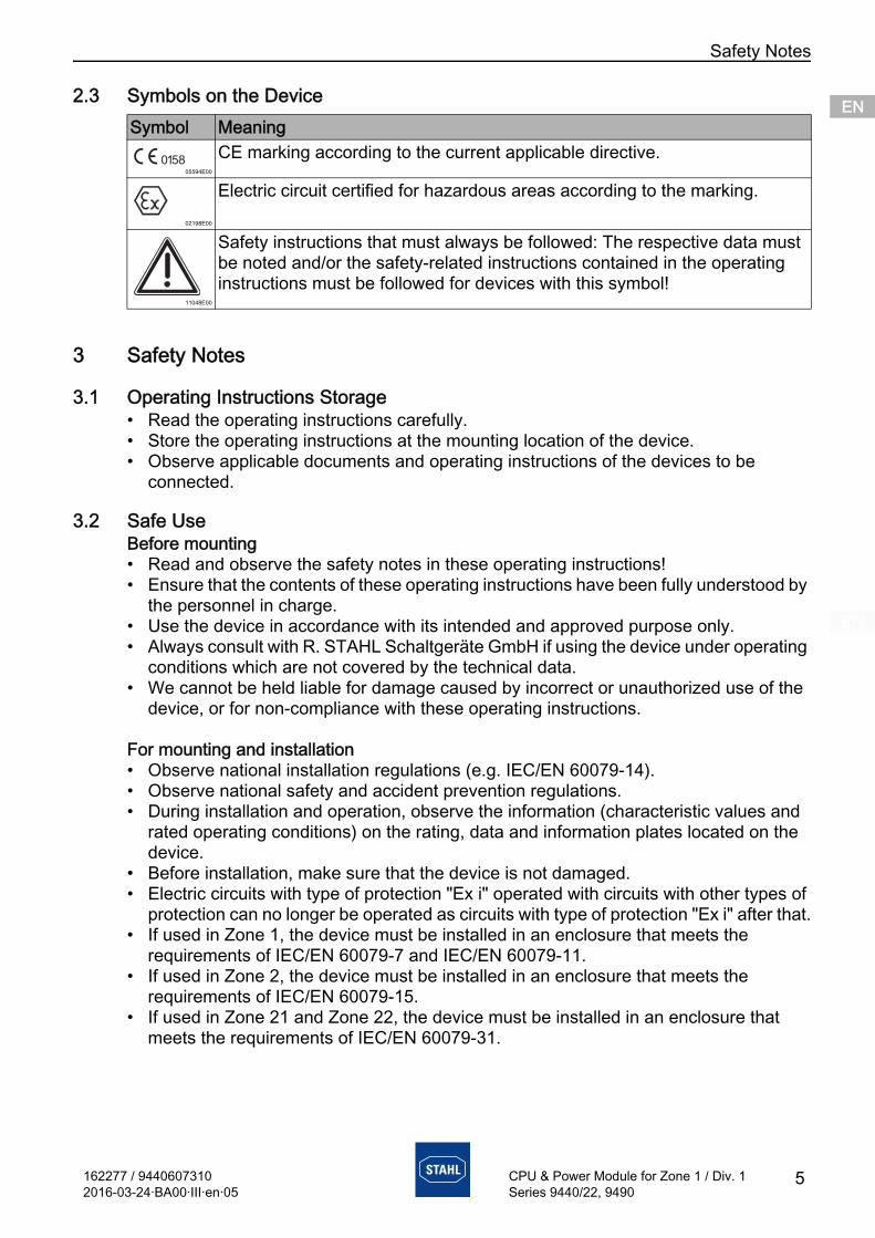
2.3 Symbols on the Device
3 Safety Notes
3.1 Operating Instructions Storage• Read the operating instructions carefully.• Store the operating instructions at the mounting location of the device.• Observe applicable documents and operating instructions of the devices to be
connected.
3.2 Safe UseBefore mounting• Read and observe the safety notes in these operating instructions!• Ensure that the contents of these operating instructions have been fully understood by
the personnel in charge.• Use the device in accordance with its intended and approved purpose only.• Always consult with R. STAHL Schaltgeräte GmbH if using the device under operating
conditions which are not covered by the technical data.• We cannot be held liable for damage caused by incorrect or unauthorized use of the
device, or for non-compliance with these operating instructions.
For mounting and installation• Observe national installation regulations (e.g. IEC/EN 60079-14).• Observe national safety and accident prevention regulations.• During installation and operation, observe the information (characteristic values and
rated operating conditions) on the rating, data and information plates located on the device.
• Before installation, make sure that the device is not damaged.• Electric circuits with type of protection "Ex i" operated with circuits with other types of
protection can no longer be operated as circuits with type of protection "Ex i" after that.• If used in Zone 1, the device must be installed in an enclosure that meets the
requirements of IEC/EN 60079-7 and IEC/EN 60079-11.• If used in Zone 2, the device must be installed in an enclosure that meets the
requirements of IEC/EN 60079-15.• If used in Zone 21 and Zone 22, the device must be installed in an enclosure that
meets the requirements of IEC/EN 60079-31.
Symbol Meaning
05594E00
CE marking according to the current applicable directive.
02198E00
Electric circuit certified for hazardous areas according to the marking.
11048E00
Safety instructions that must always be followed: The respective data must be noted and/or the safety-related instructions contained in the operating instructions must be followed for devices with this symbol!
Function and Device Design
6 162277 / 94406073102016-03-24·BA00·III·en·05
CPU & Power Module for Zone 1 / Div. 1Series 9440/22, 9490
ENENENENENENENENENENENENENENENENENENENENENENENENEN
• If installation is performed according to NEC, the Control drawing must be observed!• Guide intrinsically safe and non-intrinsically safe field circuits only in separate cable
ducts.• A minimum distance or tight string length of 50 mm ideally around an insulating or
earthed metal isolating plate must be provided between the connection points of intrinsically-safe and non-intrinsically safe circuits.
• Insulate unused conductors at the base with an unconnected cable end, e.g. by connecting to an Ex e terminal.
• Connect only one, permitted auxiliary power per base. Look up the corresponding required specific data about the connections in the "Technical data" chapter.
• Ensure degree of protection IP30 at the Ex e terminal.• Secure unoccupied connection terminals using protection against accidental contact.• Connect only conductors with a maximum cross section of 2.5 mm 2.• Galvanically isolate all devices connected to RS-485 interfaces from each other and
from all electric circuits.
Maintenance, repair, commissioning• Before commissioning, make sure that the device is not damaged.• Work on the device, such as installation, maintenance, overhaul, repair, may only be
carried out by appropriately authorised and trained personnel.• Perform only overhaul work or repair described in these operating instructions.• Always clean the device with a damp cloth to avoid electrostatic charge.
3.3 Modifications and Alterations
4 Function and Device Design
DANGERExplosion hazard due to modifications and alterations to the device!
Non-compliance results in severe or fatal injuries.• Do not modify or alter the device.
No liability or warranty for damage resulting from modifications and alterations.
DANGERExplosion hazard due to improper use!
Non-compliance results in severe or fatal injuries.• Use the device only in accordance with the operating conditions
described in these operating instructions.• Use the device only for the intended purpose specified in these
operating instructions.
162277 / 94406073102016-03-24·BA00·III·en·05
Function and Device Design
7
ENENENENENENENENENENENENENENENENENENENENENENENENEN
CPU & Power Module for Zone 1 / Div. 1Series 9440/22, 9490
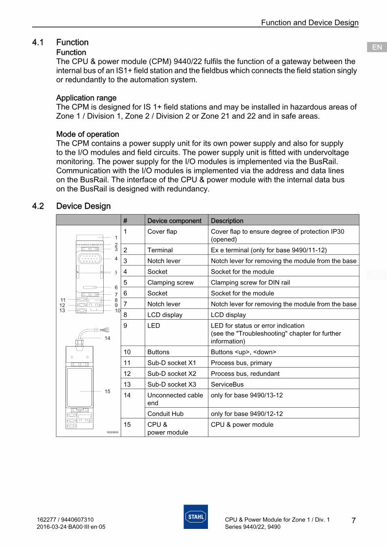
4.1 FunctionFunctionThe CPU & power module (CPM) 9440/22 fulfils the function of a gateway between the internal bus of an IS1+ field station and the fieldbus which connects the field station singly or redundantly to the automation system.
Application rangeThe CPM is designed for IS 1+ field stations and may be installed in hazardous areas of Zone 1 / Division 1, Zone 2 / Division 2 or Zone 21 and 22 and in safe areas.
Mode of operationThe CPM contains a power supply unit for its own power supply and also for supply to the I/O modules and field circuits. The power supply unit is fitted with undervoltage monitoring. The power supply for the I/O modules is implemented via the BusRail. Communication with the I/O modules is implemented via the address and data lines on the BusRail. The interface of the CPU & power module with the internal data bus on the BusRail is designed with redundancy.
4.2 Device Design# Device component Description
12223E00
1 Cover flap Cover flap to ensure degree of protection IP30 (opened)
2 Terminal Ex e terminal (only for base 9490/11-12)3 Notch lever Notch lever for removing the module from the base4 Socket Socket for the module5 Clamping screw Clamping screw for DIN rail6 Socket Socket for the module7 Notch lever Notch lever for removing the module from the base8 LCD display LCD display9 LED LED for status or error indication
(see the "Troubleshooting" chapter for further information)
10 Buttons Buttons <up>, <down>11 Sub-D socket X1 Process bus, primary 12 Sub-D socket X2 Process bus, redundant 13 Sub-D socket X3 ServiceBus 14 Unconnected cable
endonly for base 9490/13-12
Conduit Hub only for base 9490/12-1215 CPU &
power moduleCPU & power module
1
23
4
5
6
78
109
111213
15
14
Technical Data
8 162277 / 94406073102016-03-24·BA00·III·en·05
CPU & Power Module for Zone 1 / Div. 1Series 9440/22, 9490
ENENENENENENENENENENENENENENENENENENENENENENENENEN
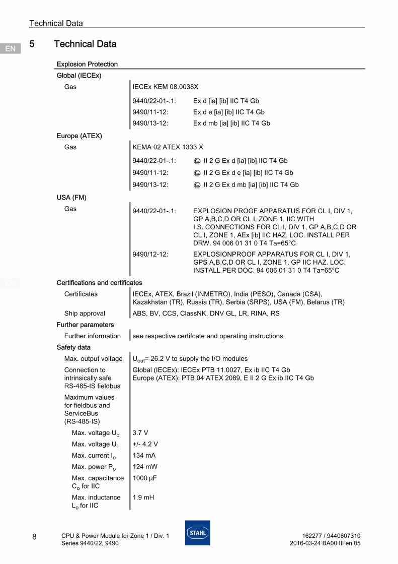
5 Technical Data
Explosion ProtectionGlobal (IECEx)
Gas IECEx KEM 08.0038X
Europe (ATEX)Gas KEMA 02 ATEX 1333 X
USA (FM)Gas
Certifications and certificatesCertificates IECEx, ATEX, Brazil (INMETRO), India (PESO), Canada (CSA),
Kazakhstan (TR), Russia (TR), Serbia (SRPS), USA (FM), Belarus (TR)Ship approval ABS, BV, CCS, ClassNK, DNV GL, LR, RINA, RS
Further parametersFurther information see respective certifcate and operating instructions
Safety dataMax. output voltage Uout= 26.2 V to supply the I/O modulesConnection to intrinsically safe RS-485-IS fieldbus
Global (IECEx): IECEx PTB 11.0027, Ex ib IIC T4 GbEurope (ATEX): PTB 04 ATEX 2089, E II 2 G Ex ib IIC T4 Gb
Maximum values for fieldbus and ServiceBus (RS-485-IS)
Max. voltage Uo 3.7 VMax. voltage Ui +/- 4.2 VMax. current Io 134 mAMax. power Po 124 mWMax. capacitance Co for IIC
1000 mF
Max. inductance Lo for IIC
1.9 mH
9440/22-01-.1: Ex d [ia] [ib] IIC T4 Gb9490/11-12: Ex d e [ia] [ib] IIC T4 Gb9490/13-12: Ex d mb [ia] [ib] IIC T4 Gb
9440/22-01-.1: E II 2 G Ex d [ia] [ib] IIC T4 Gb
9490/11-12: E II 2 G Ex d e [ia] [ib] IIC T4 Gb
9490/13-12: E II 2 G Ex d mb [ia] [ib] IIC T4 Gb
9440/22-01-.1: EXPLOSION PROOF APPARATUS FOR CL I, DIV 1, GP A,B,C,D OR CL I, ZONE 1, IIC WITH I.S. CONNECTIONS FOR CL I, DIV 1, GP A,B,C,D OR CL I, ZONE 1, AEx [ib] IIC HAZ. LOC. INSTALL PER DRW. 94 006 01 31 0 T4 Ta=65°C
9490/12-12: EXPLOSIONPROOF APPARATUS FOR CL I, DIV 1, GPS A,B,C,D OR CL I, ZONE 1, GP IIC HAZ. LOC. INSTALL PER DOC. 94 006 01 31 0 T4 Ta=65°C

162277 / 94406073102016-03-24·BA00·III·en·05
Technical Data
9
ENENENENENENENENENENENENENENENENENENENENENENENENEN
CPU & Power Module for Zone 1 / Div. 1Series 9440/22, 9490
Technical DataDesign 9440/22-01-11 (24 V DC) 9440/22-01-21 (90 to 253 V AC)Electrical data
Auxiliary powerNominal voltage 24 V DC 120 V / 230 V ACVoltage range 20 to 35 V DC 90 to 253 V ACMains frequency – 50 / 60 HzFrequency range – 45 to 66 HzCurrent consumption
without I/O modules
approx. 0.21 A at 24 V DC approx. 25 mA at 230 V AC,approx. 48 mA at 120 V AC
with 8 I/O modules
approx. 2.5 A at 24 V DC approx. 0.4 A at 230 V AC,approx. 0.8 A at 120 V AC
Power dissipationwithout I/O modules
5 W 8.4 W
per I/O module approx. 1.4 W approx. 1 WPolarity reversal protection
yes not applicable
Undervoltage monitoring
yes yes
Interfaces for fieldbus, redundant fieldbus and ServiceBus
Interface RS 485-IS acc. to Profibus specificationCable length / Transfer rate
Copper cable 1200 m with 9.6 ... 93.75 kbit/s1000 m with 187.5 kbit/s400 m with 500 kbit/s200 m with 1.5 Mbit/s
Fibre optic cable
approx. 2000 m with 1.5 Mbit/s
ServiceBus 1200 m with 9.6 kbit/sLine termination powered resistor (termination resistor is installed in the Sub-D plug,
see accessories)Address range 0 ... 127Redundancy Full redundancy and line redundancy
Technical Data
10 162277 / 94406073102016-03-24·BA00·III·en·05
CPU & Power Module for Zone 1 / Div. 1Series 9440/22, 9490
ENENENENENENENENENENENENENENENENENENENENENENENENEN
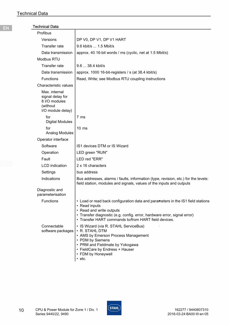
ProfibusVersions DP V0, DP V1, DP V1 HARTTransfer rate 9.6 kbit/s ... 1.5 Mbit/sData transmission approx. 40 16-bit words / ms (cyclic, net at 1.5 Mbit/s)
Modbus RTUTransfer rate 9.6 ... 38.4 kbit/sData transmission approx. 1000 16-bit-registers / s (at 38.4 kbit/s)Functions Read, Write; see Modbus RTU coupling instructions
Characteristic valuesMax. internal signal delay for 8 I/O modules (without I/O module delay)
for Digital Modules
7 ms
for Analog Modules
10 ms
Operator interfaceSoftware IS1 devices DTM or IS WizardOperation LED green "RUN"Fault LED red "ERR"LCD indication 2 x 16 charactersSettings bus addressIndications Bus addresses, alarms / faults, information (type, revision, etc.) for the levels:
field station, modules and signals, values of the inputs and outputsDiagnostic and parameterisation
•Functions • Load or read back configuration data and parameters in the IS1 field stations• Read inputs• Read and write outputs• Transfer diagnostic (e.g. config. error, hardware error, signal error)• Transfer HART commands to/from HART field devices.
•Connectable software packages
• IS Wizard (via R. STAHL ServiceBus)
• R. STAHL DTM• AMS by Emerson Process Management• PDM by Siemens• PRM and Fieldmate by Yokogawa• FieldCare by Endress + Hauser• FDM by Honeywell• etc.
Technical Data
162277 / 94406073102016-03-24·BA00·III·en·05
Technical Data
11
ENENENENENENENENENENENENENENENENENENENENENENENENEN
CPU & Power Module for Zone 1 / Div. 1Series 9440/22, 9490
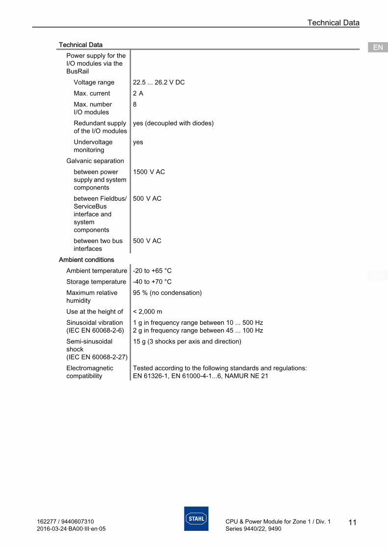
Power supply for the I/O modules via the BusRail
Voltage range 22.5 ... 26.2 V DC Max. current 2 A
Max. number I/O modules
8
Redundant supply of the I/O modules
yes (decoupled with diodes)
Undervoltage monitoring
yes
Galvanic separation between power
supply and system components
1500 V AC
between Fieldbus/ServiceBus interface and system components
500 V AC
between two bus interfaces
500 V AC
Ambient conditionsAmbient temperature -20 to +65 °CStorage temperature -40 to +70 °CMaximum relative humidity
95 % (no condensation)
Use at the height of < 2,000 mSinusoidal vibration (IEC EN 60068-2-6)
1 g in frequency range between 10 ... 500 Hz2 g in frequency range between 45 ... 100 Hz
Semi-sinusoidal shock (IEC EN 60068-2-27)
15 g (3 shocks per axis and direction)
Electromagnetic compatibility
Tested according to the following standards and regulations: EN 61326-1, EN 61000-4-1...6, NAMUR NE 21
Technical Data
Technical Data
12 162277 / 94406073102016-03-24·BA00·III·en·05
CPU & Power Module for Zone 1 / Div. 1Series 9440/22, 9490
ENENENENENENENENENENENENENENENENENENENENENENENENEN
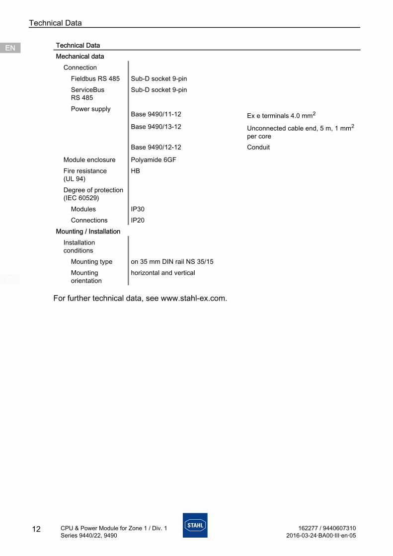
For further technical data, see www.stahl-ex.com.
Mechanical dataConnection
Fieldbus RS 485 Sub-D socket 9-pinServiceBus RS 485
Sub-D socket 9-pin
Power supply
Module enclosure Polyamide 6GFFire resistance (UL 94)
HB
Degree of protection (IEC 60529)
Modules IP30Connections IP20
Mounting / InstallationInstallation conditions
Mounting type on 35 mm DIN rail NS 35/15Mounting orientation
horizontal and vertical
Technical Data
Base 9490/11-12 Ex e terminals 4.0 mm2
Base 9490/13-12 Unconnected cable end, 5 m, 1 mm2 per core
Base 9490/12-12 Conduit
162277 / 94406073102016-03-24·BA00·III·en·05
Engineering
13
ENENENENENENENENENENENENENENENENENENENENENENENENEN
CPU & Power Module for Zone 1 / Div. 1Series 9440/22, 9490
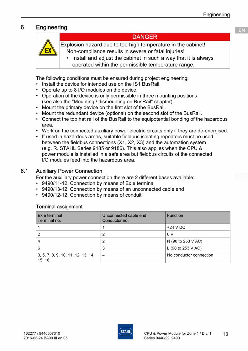
6 Engineering
The following conditions must be ensured during project engineering:• Install the device for intended use on the IS1 BusRail.• Operate up to 8 I/O modules on the device.• Operation of the device is only permissible in three mounting positions
(see also the "Mounting / dismounting on BusRail" chapter).• Mount the primary device on the first slot of the BusRail.• Mount the redundant device (optional) on the second slot of the BusRail.• Connect the top hat rail of the BusRail to the equipotential bonding of the hazardous
area.• Work on the connected auxiliary power electric circuits only if they are de-energised.• If used in hazardous areas, suitable fieldbus isolating repeaters must be used
between the fieldbus connections (X1, X2, X3) and the automation system (e.g. R. STAHL Series 9185 or 9186). This also applies when the CPU & power module is installed in a safe area but fieldbus circuits of the connected I/O modules feed into the hazardous area.
6.1 Auxiliary Power ConnectionFor the auxiliary power connection there are 2 different bases available:• 9490/11-12: Connection by means of Ex e terminal• 9490/13-12: Connection by means of an unconnected cable end• 9490/12-12: Connection by means of conduit
Terminal assignment
DANGERExplosion hazard due to too high temperature in the cabinet!
Non-compliance results in severe or fatal injuries!• Install and adjust the cabinet in such a way that it is always
operated within the permissible temperature range.
Ex e terminalTerminal no.
Unconnected cable endConductor no.
Function
1 1 +24 V DC2 2 0 V4 2 N (90 to 253 V AC)6 3 L (90 to 253 V AC)3, 5, 7, 8, 9, 10, 11, 12, 13, 14, 15, 16
– No conductor connection
Transport and Storage
14 162277 / 94406073102016-03-24·BA00·III·en·05
CPU & Power Module for Zone 1 / Div. 1Series 9440/22, 9490
ENENENENENENENENENENENENENENENENENENENENENENENENEN
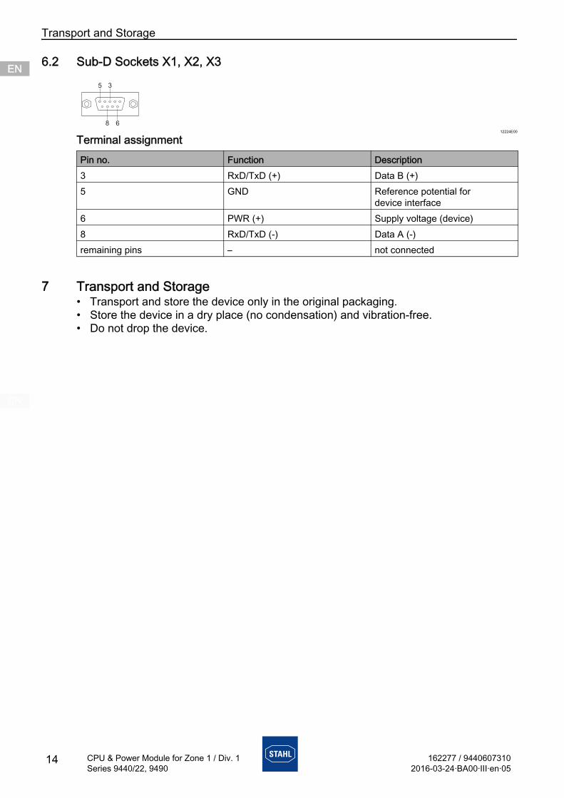
6.2 Sub-D Sockets X1, X2, X3
12224E00
Terminal assignment
7 Transport and Storage• Transport and store the device only in the original packaging.• Store the device in a dry place (no condensation) and vibration-free.• Do not drop the device.
Pin no. Function Description3 RxD/TxD (+) Data B (+)5 GND Reference potential for
device interface6 PWR (+) Supply voltage (device)8 RxD/TxD (-) Data A (-)remaining pins – not connected
5 3
8 6
162277 / 94406073102016-03-24·BA00·III·en·05
Mounting and Installation
15
ENENENENENENENENENENENENENENENENENENENENENENENENEN
CPU & Power Module for Zone 1 / Div. 1Series 9440/22, 9490
8 Mounting and InstallationThe device is approved for use in gas explosion hazardous areas of Zone 1/Division 1 and Zone 2/Division 2, in dust explosion hazardous areas of Zones 21 and 22 and in safe areas.
DANGERExplosion hazard due to installation without approved field enclosure!
Non-compliance results in severe or fatal injuries!• If used in Zone 1, the device must be installed in an enclosure
that meets the requirements of IEC/EN 60079-11 and IEC/EN 60079-7.
• If used in Zone 2, the device must be installed in an enclosure that meets the requirements of IEC/EN 60079-15.
• If used in Zone 21 and 22, the device must be installed in an enclosure that meets the requirements of IEC/EN 60079-31.
DANGERExplosion hazard due to incorrect installation of the device!
Non-compliance results in severe or fatal injuries.• Carry out installation strictly according to the instructions and
national safety and accident prevention regulations to maintain the explosion protection.
• Select and install the electrical device so that explosion protection is not affected due to external influences, i.e. pressure conditions, chemical, mechanical, thermal and electric impact such as vibration, humidity and corrosion (see IEC/EN 60079-14).
• The device must only be installed by trained qualified personnel who is familiar with the relevant standards.
Mounting and Installation
16 162277 / 94406073102016-03-24·BA00·III·en·05
CPU & Power Module for Zone 1 / Div. 1Series 9440/22, 9490
ENENENENENENENENENENENENENENENENENENENENENENENENEN
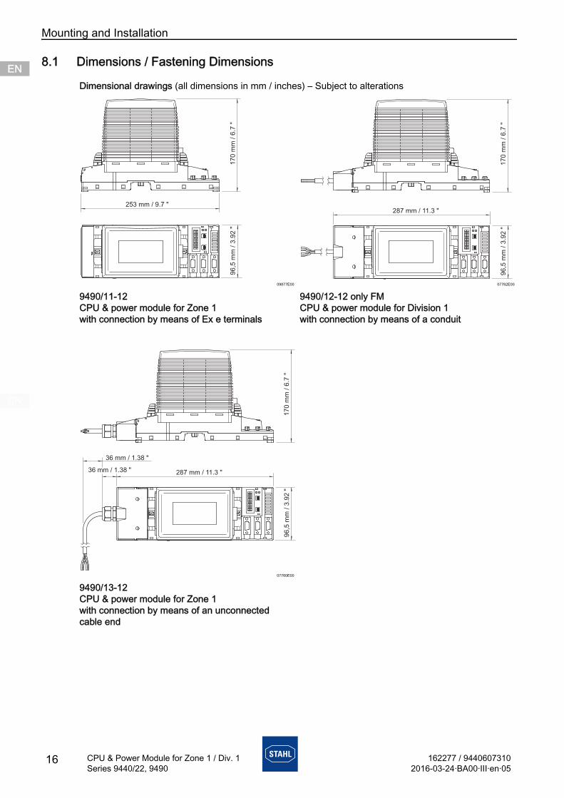
8.1 Dimensions / Fastening Dimensions
Dimensional drawings (all dimensions in mm / inches) – Subject to alterations
09877E00 07762E00
9490/11-12CPU & power module for Zone 1 with connection by means of Ex e terminals
9490/12-12 only FMCPU & power module for Division 1 with connection by means of a conduit
07760E00
9490/13-12CPU & power module for Zone 1 with connection by means of an unconnected cable end
287 mm / 11.3 "
96
,5 m
m /
3.9
2 "
17
0 m
m /
6.7
"
162277 / 94406073102016-03-24·BA00·III·en·05
Mounting and Installation
17
ENENENENENENENENENENENENENENENENENENENENENENENENEN
CPU & Power Module for Zone 1 / Div. 1Series 9440/22, 9490
8.2 Mounting / Dismounting, Operating Position
8.2.1 Mounting / Dismounting on BusRail
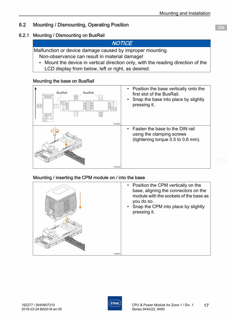
Mounting the base on BusRail
Mounting / inserting the CPM module on / into the base
NOTICEMalfunction or device damage caused by improper mounting.
Non-observance can result in material damage!• Mount the device in vertical direction only, with the reading direction of the
LCD display from below, left or right, as desired.
12225E00
• Position the base vertically onto the first slot of the BusRail.
• Snap the base into place by slightly pressing it.
17942E00
• Fasten the base to the DIN rail using the clamping screws (tightening torque 0.5 to 0.6 mm).
17939E00
• Position the CPM vertically on the base, aligning the connectors on the module with the sockets of the base as you do so.
• Snap the CPM into place by slightly pressing it.
BusRailBusRail
Mounting and Installation
18 162277 / 94406073102016-03-24·BA00·III·en·05
CPU & Power Module for Zone 1 / Div. 1Series 9440/22, 9490
ENENENENENENENENENENENENENENENENENENENENENENENENEN
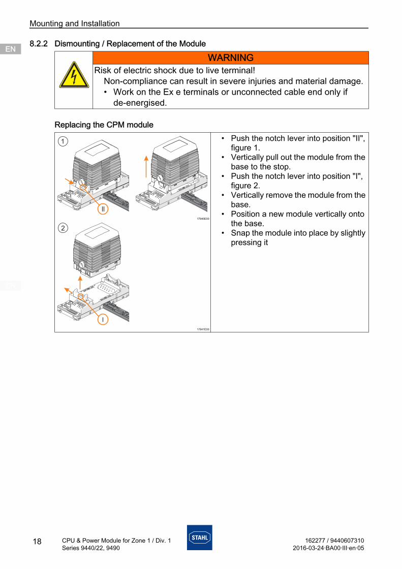
8.2.2 Dismounting / Replacement of the Module
Replacing the CPM module
WARNINGRisk of electric shock due to live terminal!
Non-compliance can result in severe injuries and material damage.• Work on the Ex e terminals or unconnected cable end only if
de-energised.
17940E00
17941E00
• Push the notch lever into position "II", figure 1.
• Vertically pull out the module from the base to the stop.
• Push the notch lever into position "I", figure 2.
• Vertically remove the module from the base.
• Position a new module vertically onto the base.
• Snap the module into place by slightly pressing it
162277 / 94406073102016-03-24·BA00·III·en·05
Mounting and Installation
19
ENENENENENENENENENENENENENENENENENENENENENENENENEN
CPU & Power Module for Zone 1 / Div. 1Series 9440/22, 9490
Replacing the base
8.3 Installation
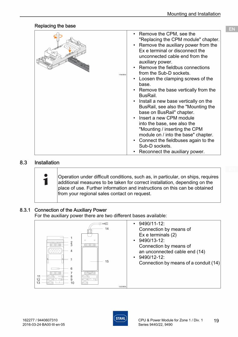
8.3.1 Connection of the Auxiliary PowerFor the auxiliary power there are two different bases available:
17943E00
• Remove the CPM, see the "Replacing the CPM module" chapter.
• Remove the auxiliary power from the Ex e terminal or disconnect the unconnected cable end from the auxiliary power.
• Remove the fieldbus connections from the Sub-D sockets.
• Loosen the clamping screws of the base.
• Remove the base vertically from the BusRail.
• Install a new base vertically on the BusRail, see also the "Mounting the base on BusRail" chapter.
• Insert a new CPM module into the base, see also the "Mounting / inserting the CPM module on / into the base" chapter.
• Connect the fieldbuses again to the Sub-D sockets.
• Reconnect the auxiliary power.
Operation under difficult conditions, such as, in particular, on ships, requires additional measures to be taken for correct installation, depending on the place of use. Further information and instructions on this can be obtained from your regional sales contact on request.
12223E00
• 9490/11-12: Connection by means of Ex e terminals (2)
• 9490/13-12: Connection by means of an unconnected cable end (14)
• 9490/12-12: Connection by means of a conduit (14)15
1
23
4
5
6
78
109
111213
14
Parameterization and Commissioning
20 162277 / 94406073102016-03-24·BA00·III·en·05
CPU & Power Module for Zone 1 / Div. 1Series 9440/22, 9490
ENENENENENENENENENENENENENENENENENENENENENENENENEN
8.3.2 Connecting the Fieldbus• Connect the primary fieldbus to the Sub-D socket X1• If necessary, connect the redundant fieldbus to the Sub-D socket X2• Secure Sub-D connector against loosening using screws
(tightening torque 0.5 ... 0.6 Nm)
8.3.3 Connecting the ServiceBus• Connect the ServiceBus to Sub-D socket X3• Secure Sub-D connector against loosening using screws
(tightening torque 0.5 ... 0.6 Nm)
9 Parameterization and Commissioning
Before commissioning, ensure the following:• Installation of the device according to regulations.• Correct connection of the cables.• No damage at the device and connection cables.• Tight seat of the screws at the terminals.
Correct tightening torque: 0.5 ... 0.6 Nm.
9.1 ParameterizationsParameterization and commissioning of the CPM and of the connected I/O modules is carried out using the automation system and the ServiceBus (optional).Only the fieldbus address of the CPM must be set directly at the base.The buttons of the LCD display in the base can be used• to set the fieldbus address of the device• to display information about the CPU & power module and the I/O modules installed
on the BusRail (see the "Display" chapter).
• Either only the auxiliary power 20 to 35 V DC for the CPM 9440/22-01-11 or 90 to 230 V AC for the CPM 9440/22-01-21 may be connected to the base. Simultaneous connection of both auxiliary powers is not permitted.
• Unused conductors at the base with an unconnected cable end must be insulated (e.g. by connecting to an Ex e terminal).
DANGERExplosion hazard due to incorrect installation!
Non-compliance results in severe or fatal injuries.• Check the device for proper installation before commissioning.• Comply with national regulations.
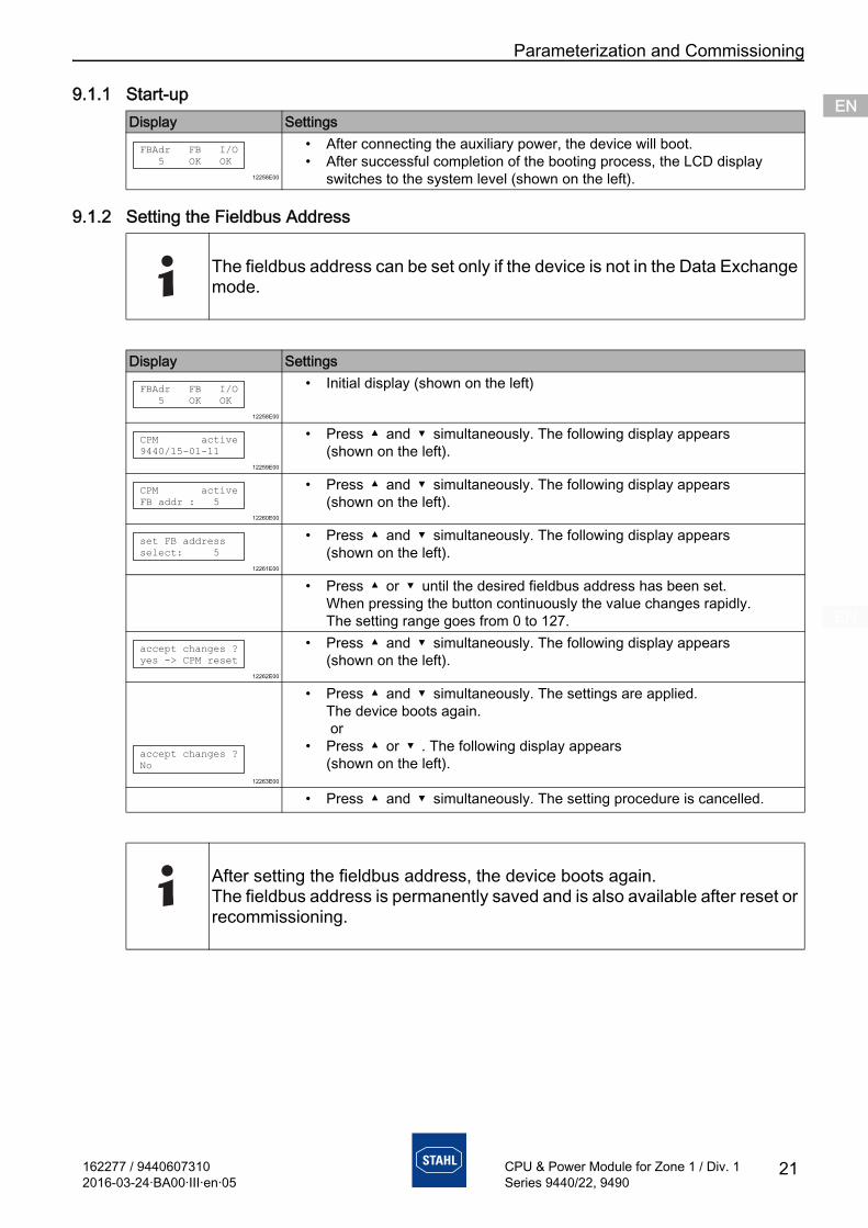
162277 / 94406073102016-03-24·BA00·III·en·05
Parameterization and Commissioning
21
ENENENENENENENENENENENENENENENENENENENENENENENENEN
CPU & Power Module for Zone 1 / Div. 1Series 9440/22, 9490
9.1.1 Start-up
9.1.2 Setting the Fieldbus Address
Display Settings
12258E00
• After connecting the auxiliary power, the device will boot.• After successful completion of the booting process, the LCD display
switches to the system level (shown on the left).
The fieldbus address can be set only if the device is not in the Data Exchange mode.
Display Settings
12258E00
• Initial display (shown on the left)
12259E00
• Press and simultaneously. The following display appears (shown on the left).
12260E00
• Press and simultaneously. The following display appears (shown on the left).
12261E00
• Press and simultaneously. The following display appears (shown on the left).
• Press or until the desired fieldbus address has been set. When pressing the button continuously the value changes rapidly. The setting range goes from 0 to 127.
12262E00
• Press and simultaneously. The following display appears (shown on the left).
12263E00
• Press and simultaneously. The settings are applied. The device boots again. or
• Press or . The following display appears (shown on the left).
• Press and simultaneously. The setting procedure is cancelled.
After setting the fieldbus address, the device boots again.The fieldbus address is permanently saved and is also available after reset or recommissioning.
FBAdr FB I/O
5 OK OK
FBAdr FB I/O
5 OK OK
CPM active
9440/15-01-11
CPM active
FB addr : 5
set FB address
select: 5
accept changes ?
yes -> CPM reset
accept changes ?
No
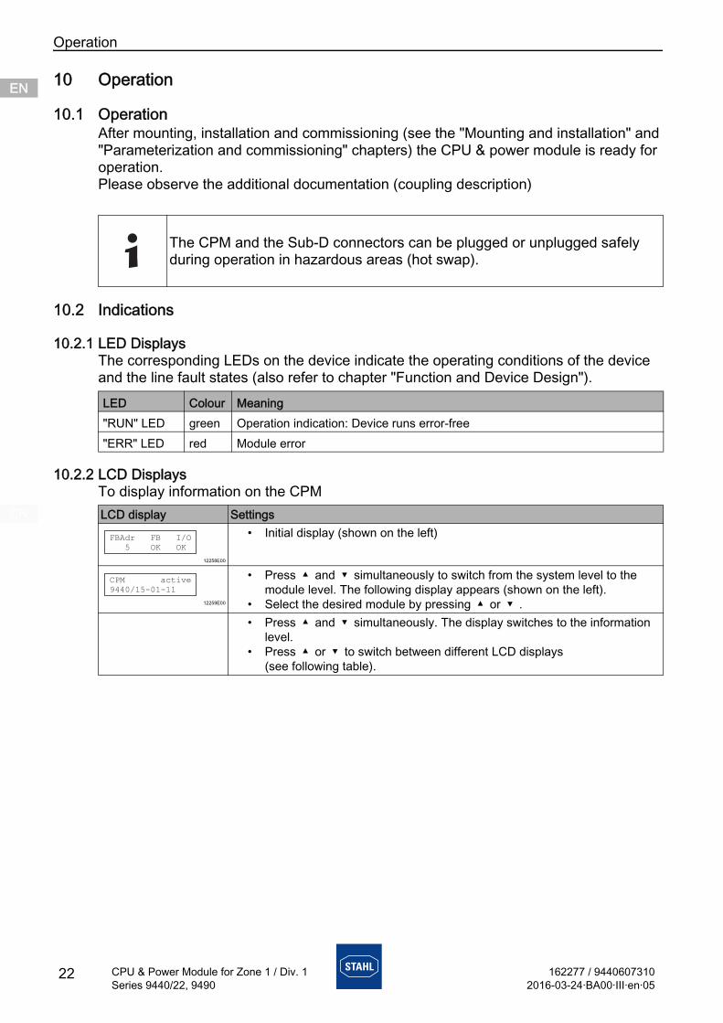
Operation
22 162277 / 94406073102016-03-24·BA00·III·en·05
CPU & Power Module for Zone 1 / Div. 1Series 9440/22, 9490
ENENENENENENENENENENENENENENENENENENENENENENENENEN
10 Operation
10.1 OperationAfter mounting, installation and commissioning (see the "Mounting and installation" and "Parameterization and commissioning" chapters) the CPU & power module is ready for operation.Please observe the additional documentation (coupling description)
10.2 Indications
10.2.1 LED DisplaysThe corresponding LEDs on the device indicate the operating conditions of the device and the line fault states (also refer to chapter "Function and Device Design").
10.2.2 LCD DisplaysTo display information on the CPM
The CPM and the Sub-D connectors can be plugged or unplugged safely during operation in hazardous areas (hot swap).
LED Colour Meaning"RUN" LED green Operation indication: Device runs error-free"ERR" LED red Module error
LCD display Settings
12258E00
• Initial display (shown on the left)
12259E00
• Press and simultaneously to switch from the system level to the module level. The following display appears (shown on the left).
• Select the desired module by pressing or .• Press and simultaneously. The display switches to the information
level.• Press or to switch between different LCD displays
(see following table).
FBAdr FB I/O
5 OK OK
CPM active
9440/15-01-11
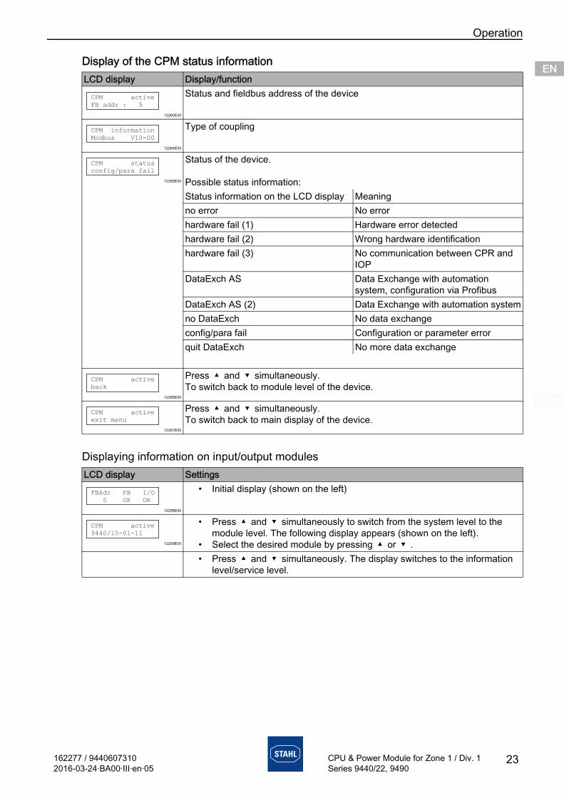
162277 / 94406073102016-03-24·BA00·III·en·05
Operation
23
ENENENENENENENENENENENENENENENENENENENENENENENENEN
CPU & Power Module for Zone 1 / Div. 1Series 9440/22, 9490
Display of the CPM status information
Displaying information on input/output modules
LCD display Display/function
12260E00
Status and fieldbus address of the device
12264E00
Type of coupling
12265E00
Status of the device.
Possible status information:Status information on the LCD display Meaningno error No errorhardware fail (1) Hardware error detectedhardware fail (2) Wrong hardware identificationhardware fail (3) No communication between CPR and
IOPDataExch AS Data Exchange with automation
system, configuration via ProfibusDataExch AS (2) Data Exchange with automation systemno DataExch No data exchangeconfig/para fail Configuration or parameter errorquit DataExch No more data exchange
12266E00
Press and simultaneously. To switch back to module level of the device.
12267E00
Press and simultaneously. To switch back to main display of the device.
LCD display Settings
12258E00
• Initial display (shown on the left)
12259E00
• Press and simultaneously to switch from the system level to the module level. The following display appears (shown on the left).
• Select the desired module by pressing or .• Press and simultaneously. The display switches to the information
level/service level.
CPM active
FB addr : 5
CPM information
Modbus V10-00
CPM status
config/para fail
CPM active
back
CPM active
exit menu
FBAdr FB I/O
5 OK OK
CPM active
9440/15-01-11

Operation
24 162277 / 94406073102016-03-24·BA00·III·en·05
CPU & Power Module for Zone 1 / Div. 1Series 9440/22, 9490
ENENENENENENENENENENENENENENENENENENENENENENENENEN
Displaying status information of the input / output modules
The following displays show the same design for all output/input modules.
LCD display Display/function
12268E00
Display of the slot, module type and module status.
Possible module statuses:Status information on the LCD display
Meaning Prio
IOM no response Communication with the module is not possible. The module is defective, not plugged in or both BusRails or the BusRail connecting cable are defective
1
hardware failure The module reports a hardware fault 2conf unequal mod Configuration error or the wrong
module was plugged in3
HW disable outp. The outputs disconnected by an external switch (installation off) (only with DOM 9475/2)
4
prim. Rail fail No communication via primary BusRail data bus
5
red. Rail fail No communication via redundant BusRail data bus
5
module OK/mode: x Module is OK. No module error. Signal errors are still possible. In addition, the configured operating mode (mode:x) is displayed
6
In case of several faults only the fault with the highest priority is displayed. After eliminating this fault the next fault with the next highest priority is displayed.
12269E00
Display of the firmware and hardware revisions.
12270E00
Display of the serial number.
slot 2: AOM
module OK/mode:0
slot 1: AOM
FW 02-04, HW ‘E’
slot 3: AOM
SNo: 123456-7890
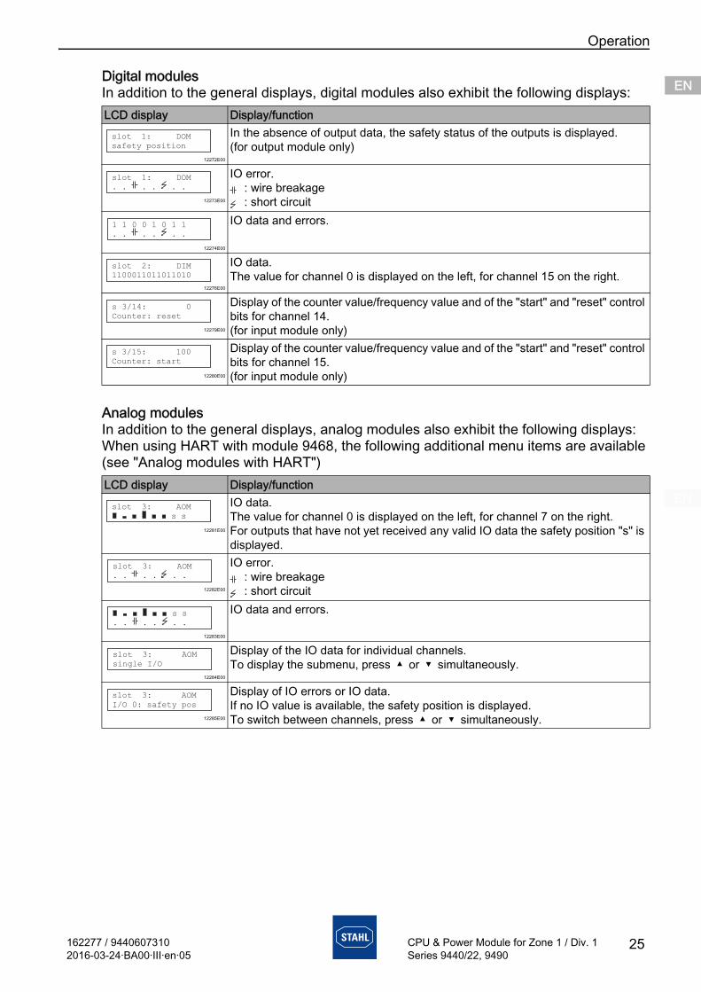
162277 / 94406073102016-03-24·BA00·III·en·05
Operation
25
ENENENENENENENENENENENENENENENENENENENENENENENENEN
CPU & Power Module for Zone 1 / Div. 1Series 9440/22, 9490
Digital modulesIn addition to the general displays, digital modules also exhibit the following displays:
Analog modulesIn addition to the general displays, analog modules also exhibit the following displays:When using HART with module 9468, the following additional menu items are available (see "Analog modules with HART")
LCD display Display/function
12272E00
In the absence of output data, the safety status of the outputs is displayed.(for output module only)
12273E00
IO error.: wire breakage: short circuit
12274E00
IO data and errors.
12276E00
IO data.The value for channel 0 is displayed on the left, for channel 15 on the right.
12279E00
Display of the counter value/frequency value and of the "start" and "reset" control bits for channel 14.(for input module only)
12280E00
Display of the counter value/frequency value and of the "start" and "reset" control bits for channel 15.(for input module only)
LCD display Display/function
12281E00
IO data.The value for channel 0 is displayed on the left, for channel 7 on the right.For outputs that have not yet received any valid IO data the safety position "s" is displayed.
12282E00
IO error.: wire breakage: short circuit
12283E00
IO data and errors.
12284E00
Display of the IO data for individual channels.To display the submenu, press or simultaneously.
12285E00
Display of IO errors or IO data.If no IO value is available, the safety position is displayed.To switch between channels, press or simultaneously.
slot 1: DOM
safety position
slot 1: DOM
. . . . . .
1 1 0 0 1 0 1 1
. . . . . .
slot 2: DIM
1100011011011010
s 3/14: 0
Counter: reset
s 3/15: 100
Counter: start
slot 3: AOM
s s
slot 3: AOM
. . . . . .
s s
. . . . . .
slot 3: AOM
single I/O
slot 3: AOM
I/O 0: safety pos
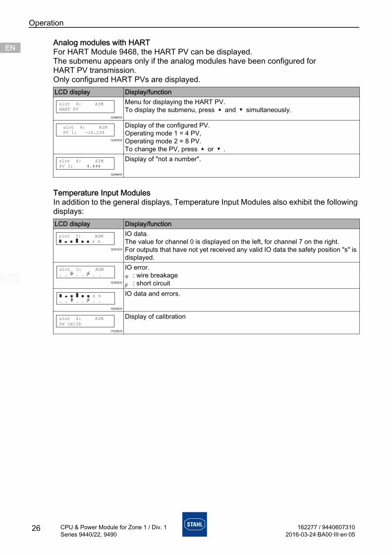
Operation
26 162277 / 94406073102016-03-24·BA00·III·en·05
CPU & Power Module for Zone 1 / Div. 1Series 9440/22, 9490
ENENENENENENENENENENENENENENENENENENENENENENENENEN
Analog modules with HARTFor HART Module 9468, the HART PV can be displayed.The submenu appears only if the analog modules have been configured for HART PV transmission.Only configured HART PVs are displayed.
Temperature Input ModulesIn addition to the general displays, Temperature Input Modules also exhibit the following displays:
LCD display Display/function
12286E00
Menu for displaying the HART PV.To display the submenu, press and simultaneously.
12287E00
Display of the configured PV.Operating mode 1 = 4 PV,Operating mode 2 = 8 PV.To change the PV, press or .
12288E00
Display of "not a number".
LCD display Display/function
12281E00
IO data.The value for channel 0 is displayed on the left, for channel 7 on the right.For outputs that have not yet received any valid IO data the safety position "s" is displayed.
12282E00
IO error.: wire breakage: short circuit
12283E00
IO data and errors.
17025E00
Display of calibration
slot 4: AIM
HART PV
slot 4: AIM
PV 1: -16.234
slot 4: AIM
PV 3: #.###
slot 3: AOM
s s
slot 3: AOM
. . . . . .
s s
. . . . . .
slot 4: AIM
2w calib
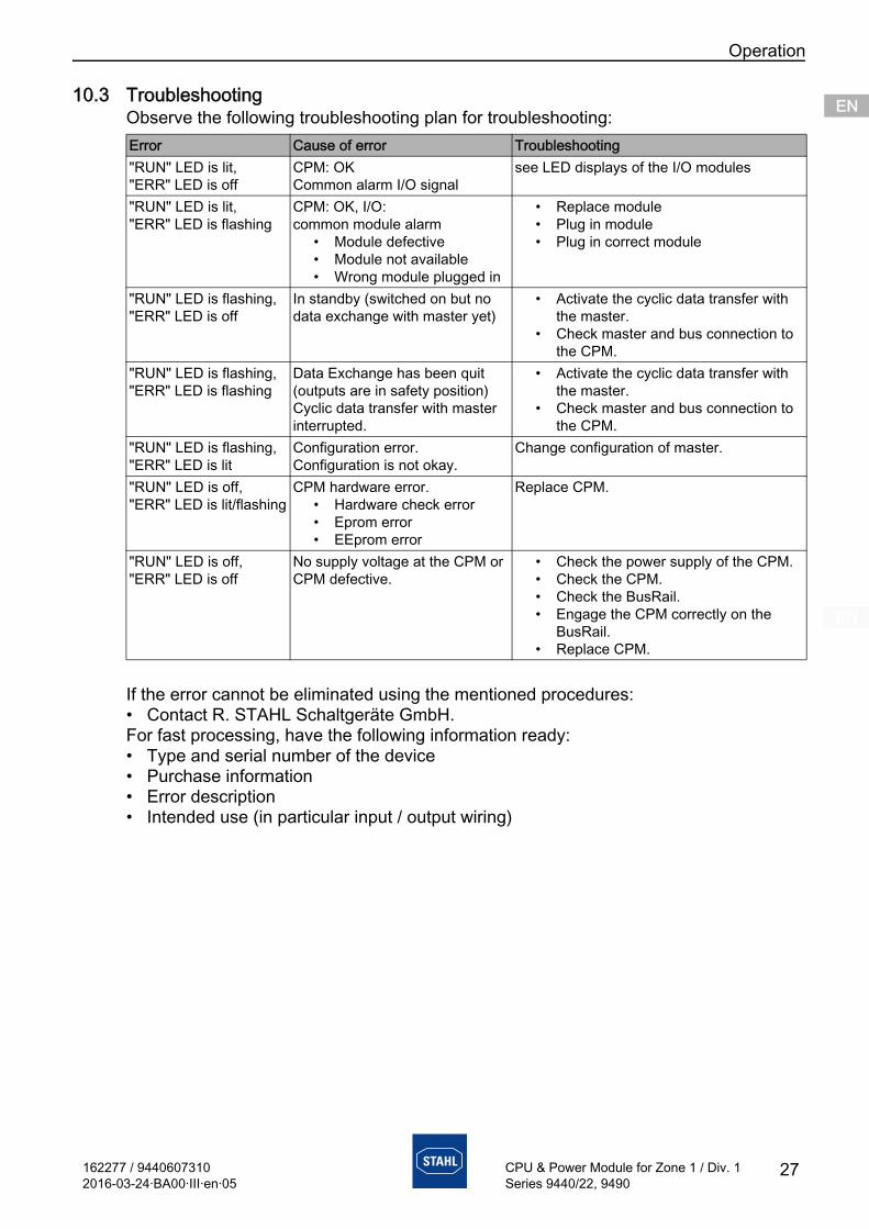
162277 / 94406073102016-03-24·BA00·III·en·05
Operation
27
ENENENENENENENENENENENENENENENENENENENENENENENENEN
CPU & Power Module for Zone 1 / Div. 1Series 9440/22, 9490
10.3 TroubleshootingObserve the following troubleshooting plan for troubleshooting:
If the error cannot be eliminated using the mentioned procedures:• Contact R. STAHL Schaltgeräte GmbH.For fast processing, have the following information ready: • Type and serial number of the device• Purchase information • Error description • Intended use (in particular input / output wiring)
Error Cause of error Troubleshooting"RUN" LED is lit,"ERR" LED is off
CPM: OKCommon alarm I/O signal
see LED displays of the I/O modules
"RUN" LED is lit,"ERR" LED is flashing
CPM: OK, I/O: common module alarm
• Module defective• Module not available• Wrong module plugged in
• Replace module• Plug in module• Plug in correct module
"RUN" LED is flashing,"ERR" LED is off
In standby (switched on but no data exchange with master yet)
• Activate the cyclic data transfer with the master.
• Check master and bus connection to the CPM.
"RUN" LED is flashing,"ERR" LED is flashing
Data Exchange has been quit (outputs are in safety position)Cyclic data transfer with master interrupted.
• Activate the cyclic data transfer with the master.
• Check master and bus connection to the CPM.
"RUN" LED is flashing,"ERR" LED is lit
Configuration error.Configuration is not okay.
Change configuration of master.
"RUN" LED is off,"ERR" LED is lit/flashing
CPM hardware error.• Hardware check error• Eprom error• EEprom error
Replace CPM.
"RUN" LED is off,"ERR" LED is off
No supply voltage at the CPM or CPM defective.
• Check the power supply of the CPM.• Check the CPM.• Check the BusRail.• Engage the CPM correctly on the
BusRail.• Replace CPM.
Maintenance and Repair
28 162277 / 94406073102016-03-24·BA00·III·en·05
CPU & Power Module for Zone 1 / Div. 1Series 9440/22, 9490
ENENENENENENENENENENENENENENENENENENENENENENENENEN
11 Maintenance and Repair
11.1 Maintenance• Consult the relevant national regulations to determine the type and extent of
inspections.• Adapt inspection intervals to the operating conditions.
During maintenance of the device, check at least:• whether the clamping screws holding the electric lines are securely seated,• whether the device enclosure and / or protective enclosure have cracks or other visible
signs of damage, • whether the permissible ambient temperatures are observed,• whether the device is used according to its designated use.
11.2 MaintenanceThe device does not require regular maintenance.
11.3 Repair
CAUTIONRisk of electric shock or malfunction of the device due to unauthorized work!
Non-compliance can result in light injuries!• Before carrying out work on the device, switch off voltage supply.• Work performed on the device must only be carried out by
authorized and appropriately trained qualified electricians.
Observe the relevant national regulations in the country of use.
DANGERExplosion hazard due to improper repair!
Non-compliance results in severe or fatal injuries.• Repair work on the devices must be performed only by
R. STAHL Schaltgeräte GmbH.
162277 / 94406073102016-03-24·BA00·III·en·05
Cleaning
29
ENENENENENENENENENENENENENENENENENENENENENENENENEN
CPU & Power Module for Zone 1 / Div. 1Series 9440/22, 9490
11.4 Returning the DeviceUse the "Service form" to return the device if repair or service is required. On the internet site "www.stahl-ex.com" under "Downloads > Customer service":• Download the service form.• Fill out the service form.• Send the device along with the service form in the original packaging to
R. STAHL Schaltgeräte GmbH.
12 Cleaning• To avoid electrostatic charging, the devices located in potentially explosive areas may
only be cleaned using a damp cloth.• When cleaning with a damp cloth, use water or mild, non-abrasive, non-scratching
cleaning agents.• Do not use aggressive detergents or solvents.
13 Disposal• Observe national and local regulations and statutory regulation regarding disposal.• Separate materials when sending it for recycling.• Ensure environmentally friendly disposal of all components according to the statutory
regulations.
14 Accessories and Spare Parts NOTE
Malfunction or damage to the device due to the use of non-original components.Non-compliance can result in material damage.• Use only original accessories and spare parts from
R. STAHL Schaltgeräte GmbH.
For accessories and spare parts, see data sheet on our homepage www.stahl-ex.com.
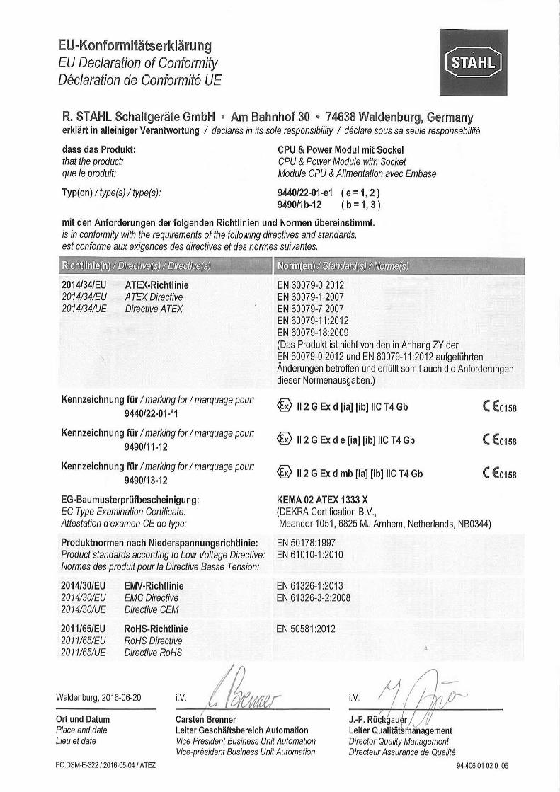
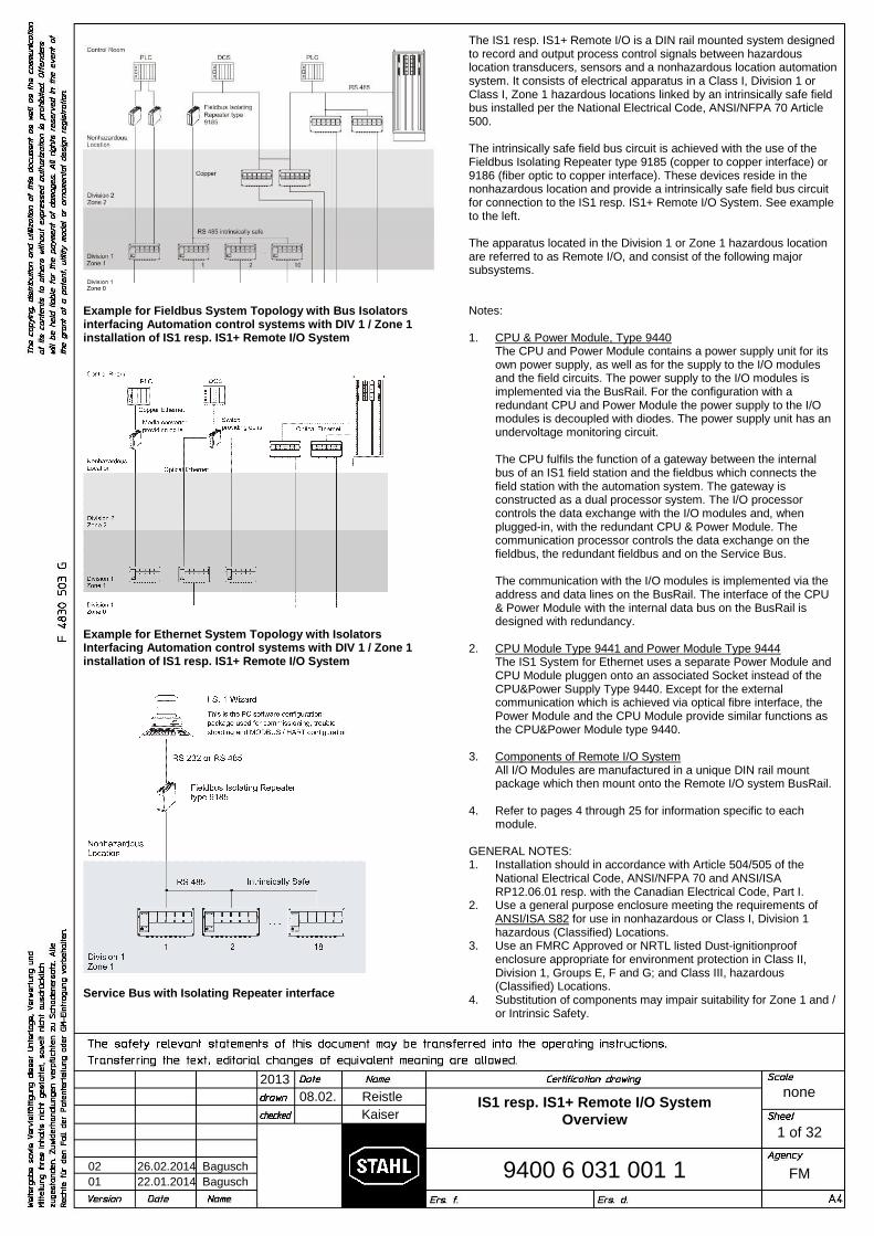
08.02. Reistle
2013
9400 6 031 001 1
none
FM
Kaiser
1 of 32
02 26.02.2014 Bagusch
01 22.01.2014 Bagusch
IS1 resp. IS1+ Remote I/O SystemOverview
Example for Fieldbus System Topology with Bus Isolatorsinterfacing Automation control systems with DIV 1 / Zone 1installation of IS1 resp. IS1+ Remote I/O System
Example for Ethernet System Topology with IsolatorsInterfacing Automation control systems with DIV 1 / Zone 1installation of IS1 resp. IS1+ Remote I/O System
Service Bus with Isolating Repeater interface
The IS1 resp. IS1+ Remote I/O is a DIN rail mounted system designedto record and output process control signals between hazardouslocation transducers, sensors and a nonhazardous location automationsystem. It consists of electrical apparatus in a Class I, Division 1 orClass I, Zone 1 hazardous locations linked by an intrinsically safe fieldbus installed per the National Electrical Code, ANSI/NFPA 70 Article500.
The intrinsically safe field bus circuit is achieved with the use of theFieldbus Isolating Repeater type 9185 (copper to copper interface) or9186 (fiber optic to copper interface). These devices reside in thenonhazardous location and provide a intrinsically safe field bus circuitfor connection to the IS1 resp. IS1+ Remote I/O System. See exampleto the left.
The apparatus located in the Division 1 or Zone 1 hazardous locationare referred to as Remote I/O, and consist of the following majorsubsystems.
Notes:
1. CPU & Power Module, Type 9440The CPU and Power Module contains a power supply unit for itsown power supply, as well as for the supply to the I/O modulesand the field circuits. The power supply to the I/O modules isimplemented via the BusRail. For the configuration with aredundant CPU and Power Module the power supply to the I/Omodules is decoupled with diodes. The power supply unit has anundervoltage monitoring circuit.
The CPU fulfils the function of a gateway between the internalbus of an IS1 field station and the fieldbus which connects thefield station with the automation system. The gateway isconstructed as a dual processor system. The I/O processorcontrols the data exchange with the I/O modules and, whenplugged-in, with the redundant CPU & Power Module. Thecommunication processor controls the data exchange on thefieldbus, the redundant fieldbus and on the Service Bus.
The communication with the I/O modules is implemented via theaddress and data lines on the BusRail. The interface of the CPU& Power Module with the internal data bus on the BusRail isdesigned with redundancy.
2. CPU Module Type 9441 and Power Module Type 9444The IS1 System for Ethernet uses a separate Power Module andCPU Module pluggen onto an associated Socket instead of theCPU&Power Supply Type 9440. Except for the externalcommunication which is achieved via optical fibre interface, thePower Module and the CPU Module provide similar functions asthe CPU&Power Module type 9440.
3. Components of Remote I/O SystemAll I/O Modules are manufactured in a unique DIN rail mountpackage which then mount onto the Remote I/O system BusRail.
4. Refer to pages 4 through 25 for information specific to eachmodule.
GENERAL NOTES:1. Installation should in accordance with Article 504/505 of the
National Electrical Code, ANSI/NFPA 70 and ANSI/ISARP12.06.01 resp. with the Canadian Electrical Code, Part I.
2. Use a general purpose enclosure meeting the requirements ofANSI/ISA S82 for use in nonhazardous or Class I, Division 1hazardous (Classified) Locations.
3. Use an FMRC Approved or NRTL listed Dust-ignitionproofenclosure appropriate for environment protection in Class II,Division 1, Groups E, F and G; and Class III, hazardous(Classified) Locations.
4. Substitution of components may impair suitability for Zone 1 and /or Intrinsic Safety.
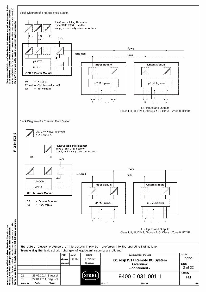
08.02. Reistle
2013
9400 6 031 001 1
none
FM
Kaiser
2 of 32
02 26.02.2014 Bagusch
01 22.01.2014 Bagusch
IS1 resp IS1+ Remote I/O SystemOverview
- continued -
Block Diagram of a RS485 Field Station
Block Diagram of a Ethernet Field Station
I.S. Inputs and OutputsClass I, II, III, DIV 1, Groups A-G; Class I, Zone 0, IIC/IIB
I.S. Inputs and OutputsClass I, II, III, DIV 1, Groups A-G; Class I, Zone 0, IIC/IIB

08.02. Reistle
2013
9400 6 031 001 1
none
FM
Kaiser
3 of 32
02 26.02.2014 Bagusch
01 22.01.2014 Bagusch
IS1 resp. IS1+ Remote I/O SystemOverview
- continued -
Construction diagram for assembly of a sample IS1 resp. IS1+ System
DIV 1 / Zone 1 Assembly Illustration shown
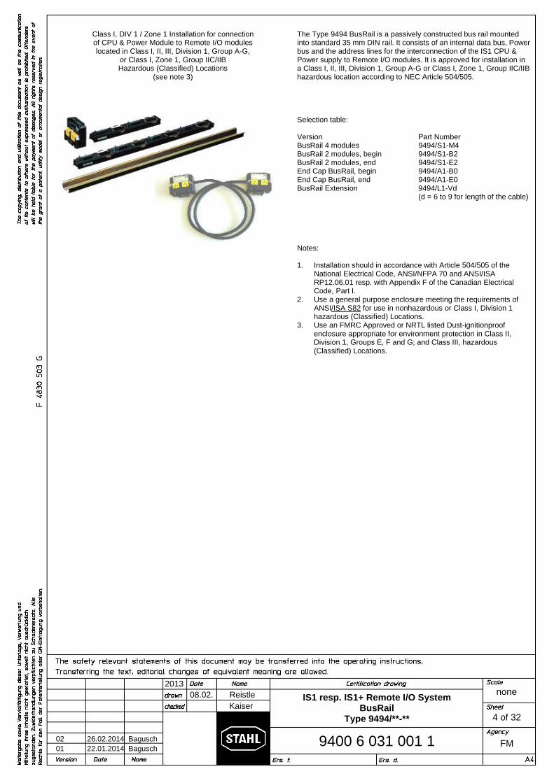
08.02. Reistle
2013
9400 6 031 001 1
none
FM
Kaiser
4 of 32
02 26.02.2014 Bagusch
01 22.01.2014 Bagusch
IS1 resp. IS1+ Remote I/O SystemBusRail
Type 9494/**-**
Class I, DIV 1 / Zone 1 Installation for connectionof CPU & Power Module to Remote I/O moduleslocated in Class I, II, III, Division 1, Group A-G,
or Class I, Zone 1, Group IIC/IIBHazardous (Classified) Locations
(see note 3)
The Type 9494 BusRail is a passively constructed bus rail mountedinto standard 35 mm DIN rail. It consists of an internal data bus, Powerbus and the address lines for the interconnection of the IS1 CPU &Power supply to Remote I/O modules. It is approved for installation ina Class I, II, III, Division 1, Group A-G or Class I, Zone 1, Group IIC/IIBhazardous location according to NEC Article 504/505.
Selection table:
Version Part NumberBusRail 4 modulesBusRail 2 modules, beginBusRail 2 modules, endEnd Cap BusRail, beginEnd Cap BusRail, endBusRail Extension
9494/S1-M49494/S1-B29494/S1-E29494/A1-B09494/A1-E09494/L1-Vd(d = 6 to 9 for length of the cable)
Notes:
1. Installation should in accordance with Article 504/505 of theNational Electrical Code, ANSI/NFPA 70 and ANSI/ISARP12.06.01 resp. with Appendix F of the Canadian ElectricalCode, Part I.
2. Use a general purpose enclosure meeting the requirements ofANSI/ISA S82 for use in nonhazardous or Class I, Division 1hazardous (Classified) Locations.
3. Use an FMRC Approved or NRTL listed Dust-ignitionproofenclosure appropriate for environment protection in Class II,Division 1, Groups E, F and G; and Class III, hazardous(Classified) Locations.
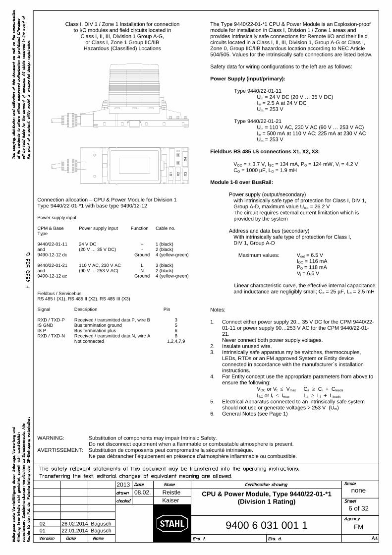
08.02. Reistle
2013
9400 6 031 001 1
none
FM
Kaiser
6 of 32
02 26.02.2014 Bagusch
01 22.01.2014 Bagusch
CPU & Power Module, Type 9440/22-01-*1(Division 1 Rating)
Class I, DIV 1 / Zone 1 Installation for connectionto I/O modules and field circuits located in
Class I, II, III, Division 1 Group A-G,or Class I, Zone 1 Group IIC/IIB
Hazardous (Classified) Locations
Connection allocation – CPU & Power Module for Division 1Type 9440/22-01-*1 with base type 9490/12-12
Power supply input
CPM & BaseType
Power supply input Function Cable no.
9440/22-01-11and9490-12-12 dc
24 V DC(20 V … 35 V DC)
+-
Ground
1 (black)2 (black)4 (yellow-green)
9440/22-01-21and9490-12-12 ac
110 V AC, 230 V AC(90 V … 253 V AC)
LN
Ground
3 (black)2 (black)4 (yellow-green)
Fieldbus / ServicebusRS 485 I (X1), RS 485 II (X2), RS 485 III (X3)
Signal Description Pin
RXD / TXD-PIS GNDIS PRXD / TXD-N
Received / transmitted data P, wire BBus termination groundBus termination plusReceived / transmitted data N, wire ANot connected
3568
1,2,4,7,9
The Type 9440/22-01-*1 CPU & Power Module is an Explosion-proofmodule for installation in Class I, Division 1 / Zone 1 areas andprovides intrinsically safe connections for Remote I/O and their fieldcircuits located in a Class I, II, III, Division 1, Group A-G or Class I,Zone 0, Group IIC/IIB hazardous location according to NEC Article504/505. Values for the intrinsically safe connections are listed below.
Safety data for wiring configurations to the left are as follows:
Power Supply (input/primary):
Type 9440/22-01-11Uin = 24 V DC (20 V … 35 V DC)Iin = 2.5 A at 24 V DCUm = 253 V
Type 9440/22-01-21Uin = 110 V AC, 230 V AC (90 V … 253 V AC)Iin = 500 mA at 110 V AC; 225 mA at 230 V ACUm = 253 V
Fieldbus RS 485 I.S connections X1, X2, X3:
VOC = 3.7 V, ISC = 134 mA, PO = 124 mW, Vi = 4.2 VCO = 1000 µF, LO = 1.9 mH
Module 1-8 over BusRail:
Power supply (output/secondary)with intrinsically safe type of protection for Class I, DIV 1,Group A-D, maximum value Uout = 26.2 VThe circuit requires external current limitation which isprovided by the system
Address and data bus (secondary)With intrinsically safe type of protection for Class I,DIV 1, Group A-D
Maximum values: Vout = 6.5 VIOC = 116 mAPO = 118 mAVi = 6.6 V
Linear characteristic curve, the effective internal capacitanceand inductance are negligibly small; Co = 25 µF, Lo = 2.5 mH
Notes:
1. Connect either power supply 20... 35 V DC for the CPM 9440/22-01-11 or power supply 90…253 V AC for the CPM 9440/22-01-21.Never connect both power supply voltages.
2. Insulate unused wire.3. Intrinsically safe apparatus my be switches, thermocouples,
LEDs, RTDs or an FM approved System or Entity deviceconnected in accordance with the manufacturer´s installationinstructions.
4. For Entity concept use the appropriate parameters from above toensure the following:
VOC or Vt Vmax Ca Ci + Cleads
ISC or It Imax La Li + Lleads
5. Electrical Apparatus connected to an intrinsically safe systemshould not use or generate voltages > 253 V (Um)
6. General Notes (see Page 1)
WARNING: Substitution of components may impair Intrinsic Safety.Do not disconnect equipment when a flammable or combustable atmosphere is present.
AVERTISSEMENT: Substitution de composants peut compromettre la sécurité intrinsèque.Ne pas débrancher l’équipement en présence d’atmosphère inflammable ou combustible.
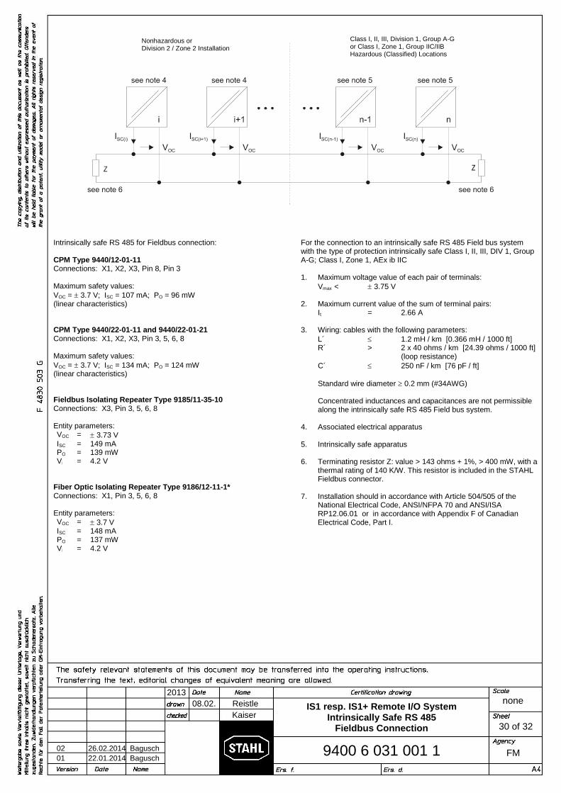
08.02. Reistle
2013
9400 6 031 001 1
none
FM
Kaiser
30 of 32
02 26.02.2014 Bagusch
01 22.01.2014 Bagusch
Intrinsically safe RS 485 for Fieldbus connection:
CPM Type 9440/12-01-11Connections: X1, X2, X3, Pin 8, Pin 3
Maximum safety values:VOC = 3.7 V; ISC = 107 mA; PO = 96 mW(linear characteristics)
CPM Type 9440/22-01-11 and 9440/22-01-21Connections: X1, X2, X3, Pin 3, 5, 6, 8
Maximum safety values:VOC = 3.7 V; ISC = 134 mA; PO = 124 mW(linear characteristics)
Fieldbus Isolating Repeater Type 9185/11-35-10Connections: X3, Pin 3, 5, 6, 8
Entity parameters:VOC = 3.73 VISC = 149 mAPO = 139 mWVi = 4.2 V
Fiber Optic Isolating Repeater Type 9186/12-11-1*Connections: X1, Pin 3, 5, 6, 8
Entity parameters:VOC = 3.7 VISC = 148 mAPO = 137 mWVi = 4.2 V
For the connection to an intrinsically safe RS 485 Field bus systemwith the type of protection intrinsically safe Class I, II, III, DIV 1, GroupA-G; Class I, Zone 1, AEx ib IIC
1. Maximum voltage value of each pair of terminals:Vmax < 3.75 V
2. Maximum current value of the sum of terminal pairs:It = 2.66 A
3. Wiring: cables with the following parameters:L´ 1.2 mH / km [0.366 mH / 1000 ft]R´ > 2 x 40 ohms / km [24.39 ohms / 1000 ft]
(loop resistance)C´ 250 nF / km [76 pF / ft]
Standard wire diameter 0.2 mm (#34AWG)
Concentrated inductances and capacitances are not permissiblealong the intrinsically safe RS 485 Field bus system.
4. Associated electrical apparatus
5. Intrinsically safe apparatus
6. Terminating resistor Z: value > 143 ohms + 1%, > 400 mW, with athermal rating of 140 K/W. This resistor is included in the STAHLFieldbus connector.
7. Installation should in accordance with Article 504/505 of theNational Electrical Code, ANSI/NFPA 70 and ANSI/ISARP12.06.01 or in accordance with Appendix F of CanadianElectrical Code, Part I.
IS1 resp. IS1+ Remote I/O SystemIntrinsically Safe RS 485
Fieldbus Connection
Class I, II, III, Division 1, Group A-Gor Class I, Zone 1, Group IIC/IIBHazardous (Classified) Locations
Nonhazardous orDivision 2 / Zone 2 Installation
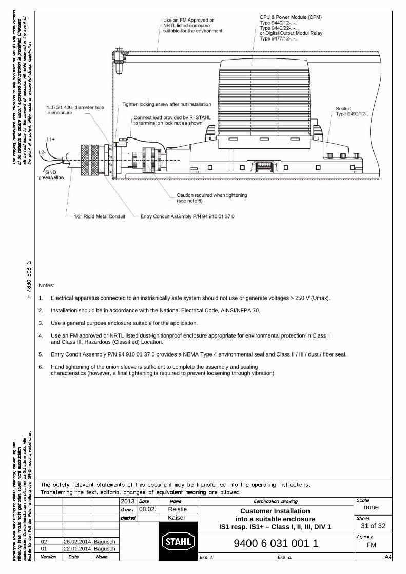
08.02. Reistle
2013
9400 6 031 001 1
none
FM
Kaiser
31 of 32
02 26.02.2014 Bagusch
01 22.01.2014 Bagusch
Notes:
1. Electrical apparatus connected to an instrisnically safe system should not use or generate voltages > 250 V (Umax).
2. Installation should be in accordance with the National Electrical Code, AINSI/NFPA 70.
3. Use a general purpose enclosure suitable for the application.
4. Use an FM approved or NRTL listed dust-ignitionproof enclosure appropriate for environmental protection in Class IIand Class III, Hazardous (Classified) Location.
5. Entry Condit Assembly P/N 94 910 01 37 0 provides a NEMA Type 4 environmental seal and Class II / III / dust / fiber seal.
6. Hand tightening of the union sleeve is sufficient to complete the assembly and sealingcharacteristics (however, a final tightening is required to prevent loosening through vibration).
Customer Installationinto a suitable enclosure
IS1 resp. IS1+ – Class I, II, III, DIV 1
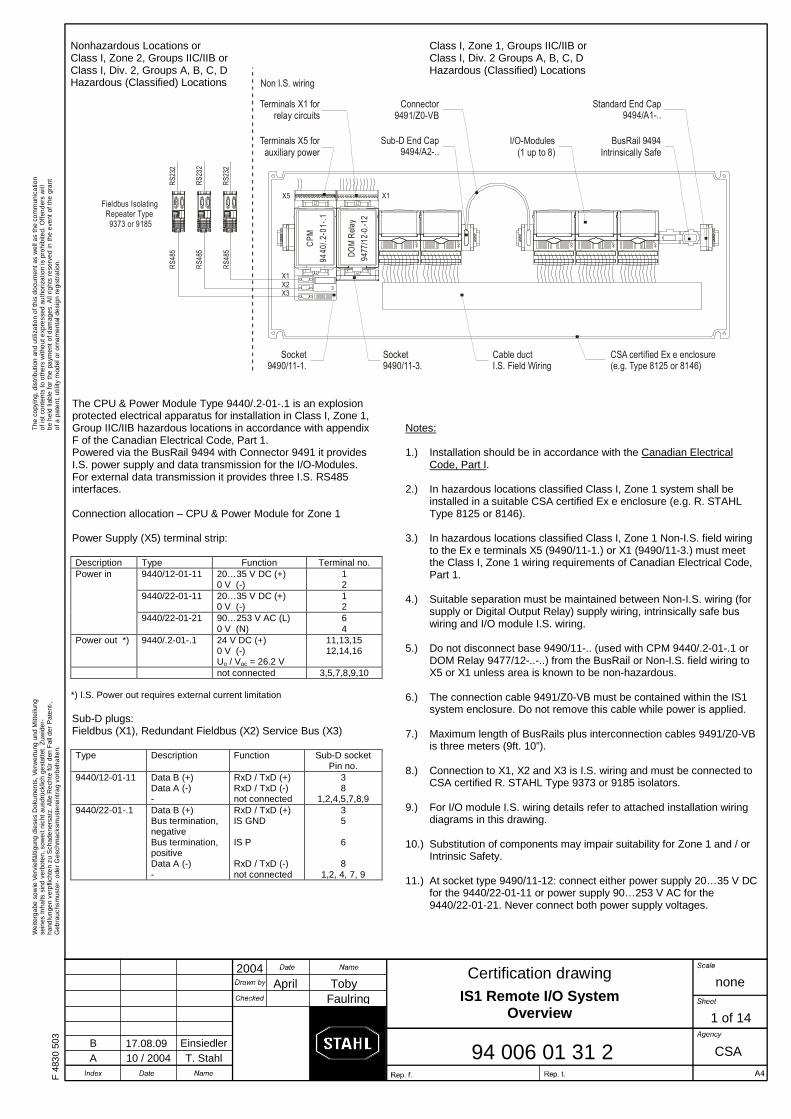
F 4
830
503
The
cop
ying
, dis
trib
utio
n an
d ut
iliza
tion
of th
is d
ocum
ent a
s w
ell a
s th
e co
mm
unic
atio
nof
ist c
onte
nts
to o
ther
s w
ithou
t exp
ress
ed a
utho
rizat
ion
is p
rohi
bite
d. O
ffend
ers
will
be h
eld
liabl
e fo
r th
e pa
ymen
t of d
amag
es. A
ll rig
hts
rese
rved
in th
e ev
ent o
f the
gra
ntof
a p
aten
t, ut
ility
mod
el o
r or
nam
enta
l des
ign
regi
stra
tion.
Wei
terg
abe
sow
ie V
ervi
elfä
ltigu
ng d
iese
s D
okum
ents
, Ver
wer
tung
und
Mitt
eilu
ngse
ines
Inha
lts s
ind
verb
oten
, sow
eit n
icht
aus
drüc
klic
h ge
stat
tet.
Zuw
ider
-ha
ndlu
ngen
ver
pflic
hten
zu
Sch
aden
ersa
tz. A
lle R
echt
e fü
r de
n F
all d
er P
aten
t-,G
ebra
uchs
mus
ter-
ode
r Ges
chm
acks
mus
tere
intr
ag v
orbe
halte
n.
Certification drawing
April Toby 2004
94 006 01 31 2
none
CSA
Faulring
A 10 / 2004 T. Stahl B 17.08.09 Einsiedler
The CPU & Power Module Type 9440/.2-01-.1 is an explosion
protected electrical apparatus for installation in Class I, Zone 1, Group IIC/IIB hazardous locations in accordance with appendix F of the Canadian Electrical Code, Part 1.
Powered via the BusRail 9494 with Connector 9491 it provides I.S. power supply and data transmission for the I/O-Modules. For external data transmission it provides three I.S. RS485 interfaces.
Connection allocation – CPU & Power Module for Zone 1
Power Supply (X5) terminal strip:
Description Type Function Terminal no. Power in 9440/12-01-11 20…35 V DC (+)
0 V (-) 1 2
9440/22-01-11 20…35 V DC (+) 0 V (-)
1 2
9440/22-01-21 90…253 V AC (L) 0 V (N)
6 4
Power out *) 9440/.2-01-.1 24 V DC (+) 0 V (-) Uo / Voc = 26.2 V
11,13,15 12,14,16
not connected 3,5,7,8,9,10 *) I.S. Power out requires external current limitation Sub-D plugs:
Fieldbus (X1), Redundant Fieldbus (X2) Service Bus (X3)
Type Description Function Sub-D socket Pin no.
9440/12-01-11 Data B (+) Data A (-) -
RxD / TxD (+) RxD / TxD (-) not connected
3 8
1,2,4,5,7,8,9 9440/22-01-.1 Data B (+)
Bus termination, negative Bus termination, positive Data A (-) -
RxD / TxD (+) IS GND IS P RxD / TxD (-) not connected
3 5 6 8
1,2, 4, 7, 9
Notes: 1.) Installation should be in accordance with the Canadian Electrical
Code, Part I. 2.) In hazardous locations classified Class I, Zone 1 system shall be
installed in a suitable CSA certified Ex e enclosure (e.g. R. STAHL Type 8125 or 8146).
3.) In hazardous locations classified Class I, Zone 1 Non-I.S. field wiring to the Ex e terminals X5 (9490/11-1.) or X1 (9490/11-3.) must meet the Class I, Zone 1 wiring requirements of Canadian Electrical Code, Part 1.
4.) Suitable separation must be maintained between Non-I.S. wiring (for
supply or Digital Output Relay) supply wiring, intrinsically safe bus wiring and I/O module I.S. wiring.
5.) Do not disconnect base 9490/11-.. (used with CPM 9440/.2-01-.1 or
DOM Relay 9477/12-..-..) from the BusRail or Non-I.S. field wiring to X5 or X1 unless area is known to be non-hazardous.
6.) The connection cable 9491/Z0-VB must be contained within the IS1
system enclosure. Do not remove this cable while power is applied. 7.) Maximum length of BusRails plus interconnection cables 9491/Z0-VB
is three meters (9ft. 10”). 8.) Connection to X1, X2 and X3 is I.S. wiring and must be connected to
CSA certified R. STAHL Type 9373 or 9185 isolators. 9.) For I/O module I.S. wiring details refer to attached installation wiring
diagrams in this drawing. 10.) Substitution of components may impair suitability for Zone 1 and / or
Intrinsic Safety. 11.) At socket type 9490/11-12: connect either power supply 20…35 V DC
for the 9440/22-01-11 or power supply 90…253 V AC for the 9440/22-01-21. Never connect both power supply voltages.
IS1 Remote I/O System Overview
Nonhazardous Locations or Class I, Zone 2, Groups IIC/IIB or Class I, Div. 2, Groups A, B, C, D Hazardous (Classified) Locations
Class I, Zone 1, Groups IIC/IIB or Class I, Div. 2 Groups A, B, C, D Hazardous (Classified) Locations
1 of 14
X5 X1
X1X2X3
DO
M R
ela
y
947
7/1
2-0.
-12
CP
M
94
40
/.2
-01
-.1
RS
232
RS
485
RS
232
RS
485
RS
232
RS
485
BusRail 9494Intrinsically Safe
Standard End Cap9494/A1-..
Sub-D End Cap9494/A2-..
Connector9491/Z0-VB
Fieldbus IsolatingRepeater Type 9373 or 9185
Cable ductI.S. Field Wiring
CSA certified Ex e enclosure(e.g. Type 8125 or 8146)
I/O-Modules(1 up to 8)
Terminals X5 forauxiliary power
Non I.S. wiring
Terminals X1 forrelay circuits
Socket 9490/11-1.
Socket 9490/11-3.
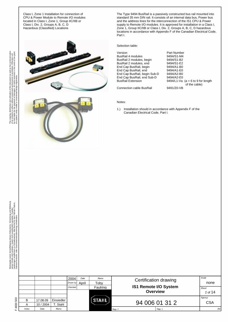
F 4
830
503
The
cop
ying
, dis
trib
utio
n an
d ut
iliza
tion
of th
is d
ocum
ent a
s w
ell a
s th
e co
mm
unic
atio
nof
ist c
onte
nts
to o
ther
s w
ithou
t exp
ress
ed a
utho
rizat
ion
is p
rohi
bite
d. O
ffend
ers
will
be h
eld
liabl
e fo
r th
e pa
ymen
t of d
amag
es. A
ll rig
hts
rese
rved
in th
e ev
ent o
f the
gra
ntof
a p
aten
t, ut
ility
mod
el o
r or
nam
enta
l des
ign
regi
stra
tion.
Wei
terg
abe
sow
ie V
ervi
elfä
ltigu
ng d
iese
s D
okum
ents
, Ver
wer
tung
und
Mitt
eilu
ngse
ines
Inha
lts s
ind
verb
oten
, sow
eit n
icht
aus
drüc
klic
h ge
stat
tet.
Zuw
ider
-ha
ndlu
ngen
ver
pflic
hten
zu
Sch
aden
ersa
tz. A
lle R
echt
e fü
r de
n F
all d
er P
aten
t-,G
ebra
uchs
mus
ter-
ode
r Ges
chm
acks
mus
tere
intr
ag v
orbe
halte
n.
Certification drawing
April Toby 2004
94 006 01 31 2
none
CSA
Faulring
A 10 / 2004 T. Stahl B 17.08.09 Einsiedler
Class I, Zone 1 Installation for connection of CPU & Power Module to Remote I/O modules located in Class I, Zone 1, Group IIC/IIB or Class I, Div. 2, Groups A, B, C, D Hazardous (Classified) Locations
The Type 9494 BusRail is a passively constructed bus rail mounted into standard 35 mm DIN rail. It consists of an internal data bus, Power bus and the address lines for the interconnection of the IS1 CPU & Power supply to Remote I/O modules. It is approved for installation in a Class I, Zone 1, Group IIC/IIB or Class I, Div. 2, Groups A, B, C, D hazardous locations in accordance with Appendix F of the Canadian Electrical Code, Part I. Selection table: Version Part Number BusRail 4 modules BusRail 2 modules, begin BusRail 2 modules, end End Cap BusRail, begin End Cap BusRail, end End Cap BusRail, begin Sub-D End Cap BusRail, end Sub-D BusRail Extension Connection cable BusRail
9494/S1-M4 9494/S1-B2 9494/S1-E2 9494/A1-B0 9494/A1-E0 9494/A2-B0 9494/A2-E0 9494/L1-Va (a = 6 to 9 for length of the cable) 9491/Z0-VB
Notes: 1.) Installation should in accordance with Appendix F of the
Canadian Electrical Code, Part I.
IS1 Remote I/O System Overview
2 of 14
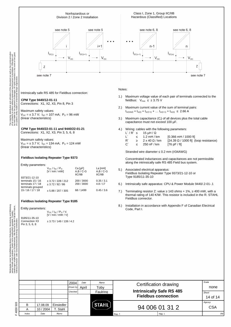
F 4
830
503
The
cop
ying
, dis
trib
utio
n an
d ut
iliza
tion
of th
is d
ocum
ent a
s w
ell a
s th
e co
mm
unic
atio
nof
ist c
onte
nts
to o
ther
s w
ithou
t exp
ress
ed a
utho
rizat
ion
is p
rohi
bite
d. O
ffend
ers
will
be h
eld
liabl
e fo
r th
e pa
ymen
t of d
amag
es. A
ll rig
hts
rese
rved
in th
e ev
ent o
f the
gra
ntof
a p
aten
t, ut
ility
mod
el o
r or
nam
enta
l des
ign
regi
stra
tion.
Wei
terg
abe
sow
ie V
ervi
elfä
ltigu
ng d
iese
s D
okum
ents
, Ver
wer
tung
und
Mitt
eilu
ngse
ines
Inha
lts s
ind
verb
oten
, sow
eit n
icht
aus
drüc
klic
h ge
stat
tet.
Zuw
ider
-ha
ndlu
ngen
ver
pflic
hten
zu
Sch
aden
ersa
tz. A
lle R
echt
e fü
r de
n F
all d
er P
aten
t-,G
ebra
uchs
mus
ter-
ode
r Ges
chm
acks
mus
tere
intr
ag v
orbe
halte
n.
Certification drawing
April Toby 2004
94 006 01 31 2
none
CSA
Faulring
A 10 / 2004 T. Stahl B 17.08.09 Einsiedler
Intrinsically safe RS 485 for Fieldbus connection: CPM Type 9440/12-01-11 Connections: X1, X2, X3, Pin 8, Pin 3 Maximum safety values: VOC = ± 3.7 V; ISC = 107 mA; PO = 96 mW (linear characteristics) CPM Type 9440/22-01-11 and 9440/22-01-21 Connections: X1, X2, X3, Pin 3, 5, 6, 8 Maximum safety values: VOC = ± 3.7 V; ISC = 134 mA; PO = 124 mW (linear characteristics) Fieldbus Isolating Repeater Type 9373 Entity parameters:
VOC / ISC / PO [V / mA / mW]
Ca [µF] A,B / C-G IIC/IIB
La [mH] A,B / C-G IIC/IIB
9373/21-12-10 terminals 15 / 16 terminals 17 / 18 terminals grouped 15 / 16 / 17 / 18
± 3.72 / 228 / 212 ± 3.72 / 92 / 86 ± 5.88 / 207 / 305
200 / 3000 200 / 3000 68 / 1499
0.35 / 3.1 4.8 / 17 0.45 / 3.6
Fieldbus Isolating Repeater Type 9185 Entity parameters:
VOC / ISC / PO / Vi [V / mA / mW / V]
9185/11-35-10 Connection X3 Pin 3, 5, 6, 8
± 3.73 / 149 / 139 / 4.2
Notes: 1.) Maximum voltage value of each pair of terminals connected to the
fieldbus: Vmax ≤ ± 3.75 V 2.) Maximum current value of the sum of terminal pairs:
Isc(total) = Isc(i) + Isc(I+1) + … Isc(n-1) + Isc(n) ≤ 2.66 A 3.) Maximum capacitance (Ci) of all devices plus the total cable
capacitance must not exceed 100 µF.
4.) Wiring: cables with the following parameters: L´ / R´ ≤ 15 µH / Ω
L´ ≤ 1.2 mH / km [0.366 mH / 1000 ft] R´ ≥ 2 x 40 Ω / km [24.39 Ω / 1000 ft] (loop resistance) C´ ≤ 250 nF / km [76 pF / ft] Stranded wire diameter ≤ 0.2 mm (#34AWG) Concentrated inductances and capacitances are not permissible along the intrinsically safe RS 485 Field bus system.
5.) Associated electrical apparatus:
Fieldbus Isolating Repeater Type 9373/21-12-10 or Type 9185/11-35-10
6.) Intrinsically safe apparatus: CPU & Power Module 9440/.2-01-.1 7.) Terminating resistor Z: value ≥ 143 ohms + 1%, ≥ 400 mW, with a
thermal rating of 140 K/W. This resistor is included in the R. STAHL Fieldbus connector.
8.) Installation in accordance with Appendix F of Canadian Electrical
Code, Part I.
14 of 14
Class I, Zone 1, Group IIC/IIB Hazardous (Classified) Locations
Nonhazardous or Division 2 / Zone 2 Installation
Intrinsically Safe RS 485 Fieldbus connection