Embed Size (px)
Citation preview
FlameGuard®
CPVC Fire Sprinkler ProductsINSTALLATION INSTRUCTIONS
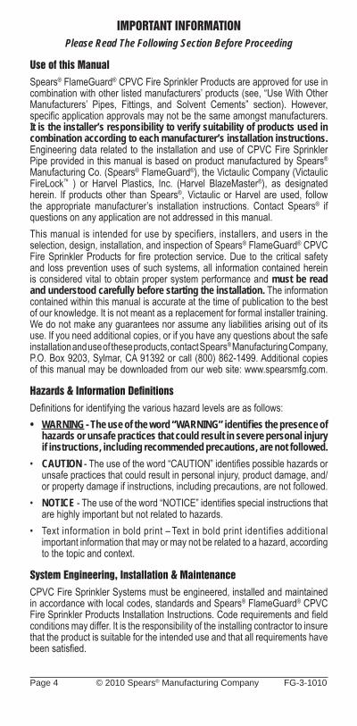
If You Feel You MUST Use Tape Sealant . . .
October 4, 2010 Printed 09/11 FG-3-1010
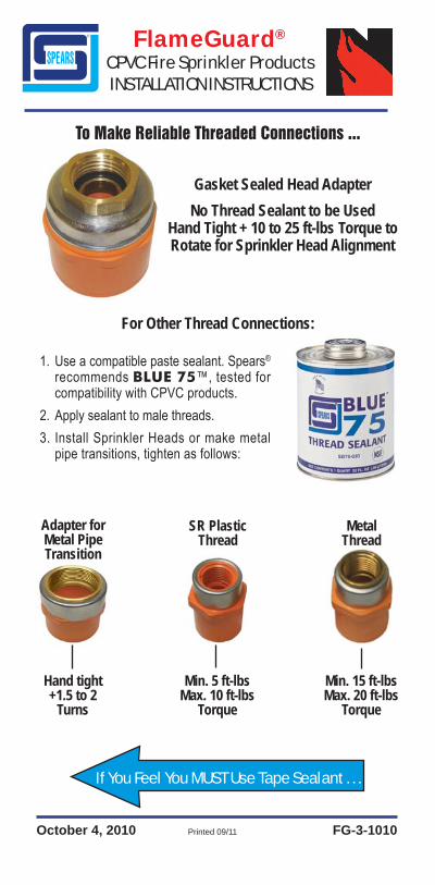
Adapter forMetal PipeTransition
SR PlasticThread
For Other Thread Connections:
MetalThread
Min. 5 ft-lbsMax. 10 ft-lbs
Torque
Hand tight+1.5 to 2
Turns
Min. 15 ft-lbsMax. 20 ft-lbs
Torque
1. Use a compatible paste sealant. Spears® recommends BLUE 75™, tested for compatibility with CPVC products.
2. Apply sealant to male threads.3. Install Sprinkler Heads or make metal
pipe transitions, tighten as follows:
Gasket Sealed Head Adapter
To Make Reliable Threaded Connections ...
No Thread Sealant to be UsedHand Tight + 10 to 25 ft-lbs Torque to Rotate for Sprinkler Head Alignment
Equipment Ltd.National FireEquipment Ltd.National Fire
Equipment Ltd.National Fire
FlameGuard® LIMITED LIFETIME WARRANTYExcept as otherwise specifi ed for certain products, mandated by law or herein provided, Spears® Manufacturing Company (“Company”) warrants Standard Catalog Products (“Products”) which have been directly manufactured by them to be free from defects in material and workmanship for as long as the original intended end user of the Products (“End User”) retains ownership and possession of the Products and complies with this Warranty (“Warranty Period”). Each other person or entity acquiring or employing the Products, including buyers, contractors and installers (“Buyer”) and End Users (“Buyer/End User”) agrees that this Warranty shall be effective only during the Warranty Period so long as the Products are used solely for the normal purposes for which they are intended and in conformance with industry established standards, engineering, installation, operating, and maintenance specifi cations, recommendations and instructions including explicit instructions by the Company; the Products are properly installed, operated and used, and have not been modifi ed; and all the other terms of this Warranty are complied with. Any violation thereof shall void this Warranty and relieve Company from all obligations arising from this Warranty and the Products.Upon receipt or discovery of any Products that appear questionable or defective each Buyer/End User shall promptly inspect and return any such Product to the Company at 15853 Olden Street, Sylmar, California 91342, accompanied by a letter stating the nature of any problems. If the Products are determined by Company to be defective in materials or workmanship directly provided by Company, Company, at its sole option, may either repair or replace the defective Products, or reimburse applicable Buyer/End User for the cost of such Products. The applicable Buyer/End User shall bear all applicable shipping costs. THIS SHALL BE BUYERS/END USERS’ SOLE REMEDY. EACH BUYER/END USER AGREES THAT COMPANY WILL NOT BE RESPONSIBLE FOR ANY OTHER OBLIGATIONS RELATING TO THE PRODUCTS, INCLUDING ANY OTHER MATERIALS OR LABOR COSTS, LOSS OF USE OR ANY OTHER ITEM OR FOR ANY DELAYS IN COMPLYING WITH THIS WARRANTY BEYOND COMPANY’S REASONABLE CONTROL. COMPANY SHALL NOT BE LIABLE FOR, DOES NOT ASSUME, AND EXPRESSLY DISCLAIMS, ANY LIABILITY, RESPONSIBILITY AND DAMAGES: DUE TO ANY BUYER/END USER’S FAILURE TO COMPLY WITH THIS WARRANTY, INCLUDING IMPROPER INSTALLATION, USE OR OPERATION; USE WITH PRODUCTS FROM OTHER MANUFACTURERS THAT DO NOT MEET ASTM OR OTHER APPLICABLE PRODUCT STANDARDS; IMPROPER CONTROL OF SYSTEM HYDRAULICS, IMPROPER WINTERIZATION PROCEDURES, IMPROPER VOLTAGE SUPPLY, CONTACT WITH INCOMPATIBLE MATERIALS OR CHEMICALS, EXCAVATION/DIGGING, EXCESSIVE WEIGHT, AND VANDALISM; DUE TO REASONABLE WEAR AND TEAR AND DUE TO ANY ACTS OF NATURE, INCLUDING LIGHTNING, EARTHQUAKES, GROUND MOVEMENT, FROST HEAVE, OR FLOODS.COMPANY EXTENDS ONLY THIS WARRANTY AND EXPLICITLY DISCLAIMS ALL OTHER WARRANTIES, WHETHER IMPLIED OR OTHERWISE EXPRESSED, WHETHER ORAL, STATUTORY OR OTHERWISE, INCLUDING ANY IMPLIED WARRANTIES OR AFFIRMATIONS FOR SUITABILITY, MERCHANTABILITY OR FITNESS FOR A PARTICULAR PURPOSE. NO AFFIRMATION BY COMPANY OR ANY OF ITS REPRESENTATIVES, BY WORDS, CONDUCT OR OTHERWISE, SHALL CONSTITUTE A WARRANTY. THIS WARRANTY MAY NOT BE TRANSFERRED, EXTENDED, ALTERED OR OTHERWISE MODIFIED IN ANY MANNER, EXCEPT BY WRITTEN AGREEMENT SIGNED BY COMPANY. BY ITS ACCEPTANCE OF THE PRODUCTS, EACH BUYER/END USER EXPRESSLY WAIVES ALL OTHER LIABILITY OR OBLIGATION OF ANY KIND OR CHARACTER OF COMPANY, INCLUDING LIABILITY PREDICATED UPON CONTRACT, TORT, STRICT LIABILITY OR OTHER LEGAL OR EQUITABLE GROUNDS, AND ALL, IF ANY, DAMAGES AND LOSSES AS A RESULT THEREOF, INCLUDING ALL, IF ANY, COMPENSATORY, GENERAL, SPECIAL, CONSEQUENTIAL, INCIDENTAL, OR PUNITIVE DAMAGES. WITH RESPECT TO SUCH WAIVERS, EACH BUYER/END USER EXPLICITLY WAIVES CALIFORNIA CIVIL CODE §1542 WHICH STATES “A GENERAL RELEASE DOES NOT EXTEND TO CLAIMS WHICH THE CREDITOR DOES NOT KNOW OR SUSPECT TO EXIST IN HIS FAVOR AT THE TIME OF EXECUTING THIS RELEASE, WHICH IF KNOWN BY HIM MUST HAVE MATERIALLY ADVERSELY AFFECTED HIS SETTLEMENT WITH DEBTOR” AND ALL OTHER SIMILAR STATUTORY, COMMON AND CASE LAW RIGHTS, DEFENSES AND LIMITATIONS. Having previously independently inspected the Products, or a sample, as fully as desired, or having the opportunity to and having not done so, upon acceptance of delivery of the Products, and except as otherwise herein explicitly provided, each Buyer/End User by acceptance or use of the Products accepts them in their “AS IS” and “WITH ALL FAULTS” condition without any other warranty, expressed, implied or otherwise, and accepts and assumes the entire risk and cost of all servicing, remediation and consequences thereof. This Warranty shall be governed by California law and any unenforceable provisions severed without affecting the remaining provisions. As used herein, “including” includes “without limitation.”
FG-3-1010 © 2010 Spears® Manufacturing Company Page 3
TABLE OF CONTENTSWarranty .......................................................................................................... Inside CoverIMPORTANT INFORMATION ..............................................................................................4 Use of this Manual • Hazards & Information Defi nitions ...............................................4 System Engineering, Installation & Maintenance ..........................................................4 Installer Training ............................................................................................................5General Installation Safety Instructions ...........................................................................5Introduction .........................................................................................................................5Handling & Storage ............................................................................................................6 Pipe & Fittings ...............................................................................................................6 One-Step Solvent Cement ............................................................................................6Listing, Approvals, Application & Use ..............................................................................7 Light Hazard Occupancies ............................................................................................7 Residential Occupancies ...............................................................................................7 Low Pressure Dry Pipe and Pre-action Systems ..........................................................8 Concealed Installations .................................................................................................9 Combustible Concealed Installation with Specifi c Use Sprinklers.................................9 Combustible Attic Spaces with Specifi c Use Sprinklers ..............................................10 Exposed Installations ..................................................................................................10 Expanded Use with Light Hazard Extended Coverage and Residential Sprinklers ....10 Unfi nished Basement with Exposed Solid Wood Joist Installation ..............................11 Extended Coverage Quick Response Sprinklers ........................................................14 Return Air Plenum Installation • Garage Installations ..................................................15 Ambient Temperature Limitations • High Temperature Areas ......................................15 Cold Temperature Areas ............................................................................................. 15 Fire Sprinkler System Risers .......................................................................................16 Underground Fire Service • C-UL Listing Requirements .............................................18 Factory Mutual Approvals ............................................................................................20 Loss Prevention Certifi cation Board LPCB..................................................................20 NSF® International .......................................................................................................21 Penetrating Fire-related Walls & Partitions .................................................................21 Heat Sources & Open Ceiling Areas ...........................................................................21 Use With Other Manufacturers’ Pipes, Fittings & Solvent Cement .............................22Installation & Joining .......................................................................................................22 Solvent Cement Welded Joints ...................................................................................22 Solvent Cement Requirements ...................................................................................27 Threaded Connections ................................................................................................27 TorqueSafe™Gasket Sealed Thread Connections .......................................................29 Painting Pipe & Fittings • Cleaning ..............................................................................30 Transition to Other Materials • Flanged Connections ..................................................30 Flange Data & Bolt Torque • Grooved Coupling Adapters ...........................................31 Adjustable Sprinkler Head Adapter Installation ...........................................................33 Flushing System .........................................................................................................34 System Acceptance Testing (Hydrostatic Pressure Test) ..........................................34 Recommended Cut-in Procedures for Systems Modifi cation or Repair ......................35Engineering Data ..............................................................................................................37 Pipe & Fitting Specifi cations • Hydraulic Design .........................................................37 Allowance for Friction Loss in Fittings .........................................................................38 Hanger & Supports ......................................................................................................38 Riser Support ..............................................................................................................41 Exposed Installations • Earthquake Bracing • Trenching ............................................42 Snaking/Defl ection of Pipe ..........................................................................................43 Backfi lling ....................................................................................................................45 Material Properties ......................................................................................................46 Expansion & Contraction .............................................................................................47 Expansion Loop & Offset Confi gurations ....................................................................49Review - Do’s & Don’ts.....................................................................................................52Material Safety Data Sheet ...............................................................................................53
Page 4 © 2010 Spears® Manufacturing Company FG-3-1010
IMPORTANT INFORMATIONPlease Read The Following Section Before Proceeding
Use of this ManualSpears® FlameGuard® CPVC Fire Sprinkler Products are approved for use in combination with other listed manufacturers’ products (see, “Use With Other Manufacturers’ Pipes, Fittings, and Solvent Cements” section). However, specifi c application approvals may not be the same amongst manufacturers. It is the installer’s responsibility to verify suitability of products used in combination according to each manufacturer’s installation instructions. Engineering data related to the installation and use of CPVC Fire Sprinkler Pipe provided in this manual is based on product manufactured by Spears® Manufacturing Co. (Spears® FlameGuard®), the Victaulic Company (Victaulic FireLock™ ) or Harvel Plastics, Inc. (Harvel BlazeMaster®), as designated herein. If products other than Spears ®, Victaulic or Harvel are used, follow the appropriate manufacturer’s installation instructions. Contact Spears® if questions on any application are not addressed in this manual.This manual is intended for use by specifiers, installers, and users in the selection, design, installation, and inspection of Spears® FlameGuard® CPVC Fire Sprinkler Products for fi re protection service. Due to the critical safety and loss prevention uses of such systems, all information contained herein is considered vital to obtain proper system performance and must be read and understood carefully before starting the installation. The information contained within this manual is accurate at the time of publication to the best of our knowledge. It is not meant as a replacement for formal installer training. We do not make any guarantees nor assume any liabilities arising out of its use. If you need additional copies, or if you have any questions about the safe installation and use of these products, contact Spears® Manufacturing Company, P.O. Box 9203, Sylmar, CA 91392 or call (800) 862-1499. Additional copies of this manual may be downloaded from our web site: www.spearsmfg.com.
Hazards & Information Defi nitionsDefi nitions for identifying the various hazard levels are as follows:• WARNING - The use of the word “WARNING” identifi es the presence of
hazards or unsafe practices that could result in severe personal injury if instructions, including recommended precautions, are not followed.
• CAUTION - The use of the word “CAUTION” identifi es possible hazards or unsafe practices that could result in personal injury, product damage, and/or property damage if instructions, including precautions, are not followed.
• NOTICE - The use of the word “NOTICE” identifi es special instructions that are highly important but not related to hazards.
• Text information in bold print – Text in bold print identifies additional important information that may or may not be related to a hazard, according to the topic and context.
System Engineering, Installation & MaintenanceCPVC Fire Sprinkler Systems must be engineered, installed and maintained in accordance with local codes, standards and Spears® FlameGuard® CPVC Fire Sprinkler Products Installation Instructions. Code requirements and fi eld conditions may differ. It is the responsibility of the installing contractor to insure that the product is suitable for the intended use and that all requirements have been satisfi ed.

FG-3-1010 © 2010 Spears® Manufacturing Company Page 5
Installer TrainingSpears® Manufacturing Company recommends that installers receive proper installation training and that training be renewed every two (2) years. Training will be provided at no charge by contacting an authorized Spears® FlameGuard® CPVC Fire Sprinkler Products distributor or your nearest Spears® Regional Distribution Center.
General Installation Safety Instructions• Use only recommended accessories. Use of improper accessories or
unapproved system components in conjunction with Spears® FlameGuard® CPVC Fire Sprinkler Products will void the warranty and may result in improper operation of the system.
• CAUTION: Avoid dangerous environments. If utilizing electrically powered tools for installation, be sure that the area is free of moisture or wetness that could create an unsafe condition. Keep work area clean and well illuminated. Allow sufficient space for measuring and system dry-fit to accommodate proper installation.
• Prevent back injury. Always practice safe lifting and installation techniques.• Use only tools specifi cally designed for plastic pipe and fi ttings.• Inspect the products. Be sure that all parts are included and that you have
all necessary tools available to properly install the system.
CAUTION: Follow all workplace safety requirements. Wear safety glasses, hardhat, and safety footwear. Always practice safety fi rst.
• When solvent cementing, always work in a well-ventilated area. Avoid sources of heat or open fl ames. DO NOT smoke. Wear protective gloves. PVA-coated protective gloves are recommended for use while solvent cementing. If hands come in contact with solvent cement, use a waterless, abrasive soap.
• Wear ear protection. Protect your hearing if you are exposed to long periods of very noisy job-site operations.
INTRODUCTION
Spears® FlameGuard® CPVC Fire Sprinkler Products are manufactured from high quality, Post-Chlorinated Poly Vinyl Chloride (CPVC), a specialty thermoplastic material tested and approved by certifying agencies for use in CPVC fi re sprinkler systems. Spears® FlameGuard® CPVC Fire Sprinkler Products provide unique advantages over traditional metal fi re sprinkler systems through superior hydraulics, ease of installation and handling and quick assembly using readily available, inexpensive tools.
Page 6 © 2010 Spears® Manufacturing Company FG-3-1010
Handling & StoragePipe & FittingsSpears® FlameGuard® CPVC Fire Sprinkler Products resist attack from a large group of chemicals that are corrosive to metallic piping. However, care must be taken to avoid contact with chemicals that are harmful to CPVC including those found in some common construction products. Specifi c chemicals or chemical vapors that contact CPVC can weaken or severely damage the system. Consult with the chemical manufacturer or Spears® before use.WARNING: DO NOT expose Spears® FlameGuard® CPVC Fire Sprinkler Products to edible oils, esters, ketones, or petroleum-based products, such as cutting oils, packing oils, traditional pipe thread paste or dopes, and some lubricants. Do not store or install CPVC products in direct contact with plasticizer containing materials such as electrical tape or certain wire and cable insulations. Consult with the chemical manufacturer for compatibility with CPVC or Spears® before use. Contact with incompatible chemicals could cause serious personal injury, property damage, and product damage.Spears® FlameGuard® CPVC Fire Sprinkler Pipe should be stored indoors with a maximum storage temperature of 110° F (43° C). If storing outdoors, the products must be covered with a non-transparent material to prevent extended exposure to sunlight. Brief exposure to direct sunlight on the job site may result in color fade, but it will not affect the physical properties. Spears® FlameGuard® CPVC Fire Sprinkler Fittings should be stored indoors in their original containers to keep them free from dirt and to help reduce the possibility of damage.WARNING: Spears® FlameGuard® CPVC Fire Sprinkler Products must not be subjected to prolonged sunlight exposure. The use of pipe and fi ttings that have been damaged due to improper storage could cause serious personal injury, property damage, and product damage.Reasonable care must be exercised in handling Spears® FlameGuard® CPVC Fire Sprinkler Products. DO NOT drop the products or drop anything on them. If improper handling results in scratches, splits, or gouges, the damaged fi tting or section of pipe must be discarded.WARNING: DO NOT install Spears® FlameGuard® CPVC Fire Sprinkler Products that have been scratched, split, or gouged. The use of pipe and fi ttings that have been damaged due to improper handling could cause serious personal injury, property damage, and product damage.One-Step Solvent CementSpears® FS-5 One-Step Low VOC Solvent Cement must be stored out of direct sunlight in an ambient temperature between 40° F (4° C) and 90° F (32° C). The solvent cement may be used for a period of two years from the date stamped on the container. Expired solvent cement must be discarded in an environmentally friendly fashion, in accordance with local regulations. To prolong the life of the cement, the containers must be kept tightly closed when not in use and covered as much as possible when in use.WARNING: • Spears® FS-5 One-Step Low VOC Solvent Cement is highly fl ammable.
Eliminate all ignition sources.• Avoid breathing vapors. Use only with adequate ventilation.
Explosion-proof, general mechanical ventilation or local exhaust is recommended to maintain vapor concentrations below recommended exposure limits. In confi ned or partially enclosed areas, a NIOSH approved organic vapor cartridge respirator with a full face-piece is recommended. Avoid frequent contact with skin. It is recommended that you wear PVA coated gloves and an impervious apron.
FG-3-1010 © 2010 Spears® Manufacturing Company Page 7
• Avoid contact with eyes. Splash-proof chemical goggles are recommended.
• Review the Material Safety Data Sheet (MSDS) and the important product information provided on the label for Spears® FS-5 One-Step Low VOC Solvent Cement.
Failure to follow the above recommendations could result in death or serious personal injury.
Listings, Approvals, Application & UseSpears® FlameGuard® CPVC Fire Sprinkler Products are fully tested and approved for use in wet pipe fi re sprinkler systems by Underwriters Laboratories Inc., FM Global, and the Loss Prevention Certifi cation Board. Spears® FlameGuard® CPVC Fire Sprinkler Products are approved for use in low pressure dry pipe or pre-action systems by Underwriters Laboratories Inc. Spears® FlameGuard® CPVC Fire Sprinkler Products are listed by NSF® International for use in potable water systems. For specifi c listing information not covered in this manual concerning Factory Mutual, The Loss Prevention Certifi cation Board or NSF® International, please contact your nearest Spears® Regional Distribution Center.NOTICE: National Fire Protection Association (NFPA) Standards 13, 13R, and 13D must be referenced for design and installation requirements in conjunction with this manual and all local codes.CAUTION: Spears® FlameGuard® CPVC Fire Sprinkler Products are NOT listed for outdoor applications. Outdoor installation could result in product failure and property damage and will not be covered under the Spears® FlameGuard® CPVC Fire Sprinkler Products warranty.CAUTION: Spears® FlameGuard® CPVC Fire Sprinkler Products are to be used in wet pipe systems only, except as provided for dry pipe or pre-action systems in this manual. A wet pipe system is one that contains water and is connected to a water supply system so that the water will discharge immediately when the sprinkler is opened. A low pressure dry pipe or pre-action system is a piping system containing air or nitrogen under pressure that is release with the opening of a sprinkler which activates a special dry pipe valve allowing water to fl ow into the piping system and to the open sprinkler.WARNING: Spears® FlameGuard® CPVC Fire Sprinkler Products must never be used for distribution of compressed air or other gases except as provided for under Low Pressure Dry Pipe and Pre-action Systems specifi ed in this manual. Failure to follow this warning could result in product failure, property damage and severe personal injury or death.Light Hazard OccupanciesSpears® FlameGuard® CPVC Fire Sprinkler Products are UL Listed for use in Light Hazard Occupancies, as defi ned in the NFPA 13.In accordance with NFPA 13, 2002 Edition paragraph 6.3.6.2, “Pipe or tube listed for light hazard occupancies shall be permitted to be installed in ordinary hazard rooms of otherwise light hazard occupancies where the room does not exceed 400 square feet”. NOTICE: Local jurisdictions must approve of this exception.Residential OccupanciesSpears® FlameGuard® CPVC Fire Sprinkler Products are UL Listed for use in:Residential occupancies up to and including four stories in height, as defi ned in NFPA 13R.Residential occupancies, as defined in the Standard for the Installation of Sprinkler Systems in One and Two Family Dwellings and Manufactured Homes, NFPA 13D.
Page 8 © 2010 Spears® Manufacturing Company FG-3-1010
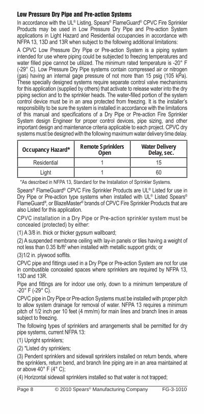
Low Pressure Dry Pipe and Pre-action SystemsIn accordance with the UL® Listing, Spears® FlameGuard® CPVC Fire Sprinkler Products may be used in Low Pressure Dry Pipe and Pre-action System applications in Light Hazard and Residential occupancies in accordance with NFPA 13, 13D and 13R when subject to the following additional limitations:A CPVC Low Pressure Dry Pipe or Pre-action System is a piping system intended for use where piping could be subjected to freezing temperatures and water fi lled pipe cannot be utilized. The minimum rated temperature is -20° F (-29° C). Low Pressure Dry Pipe systems contain compressed air or nitrogen (gas) having an internal gage pressure of not more than 15 psig (105 kPa). These specially designed systems require separate control valve mechanisms for this application (supplied by others) that activate to release water into the dry piping section and to the sprinkler heads. The water-fi lled portion of the system control device must be in an area protected from freezing. It is the installer’s responsibility to be sure the system is installed in accordance with the limitations of this manual and specifi cations of a Dry Pipe or Pre-action Fire Sprinkler System design Engineer for proper control devices, pipe sizing, and other important design and maintenance criteria applicable to each project. CPVC dry systems must be designed with the following maximum water delivery time delay.
Occupancy Hazard* Remote Sprinklers Open
Water Delivery Delay, sec.
Residential 1 15Light 1 60
*As described in NFPA 13, Standard for the Installation of Sprinkler Systems.Spears® FlameGuard® CPVC Fire Sprinkler Products are UL® Listed for use in Dry Pipe or Pre-action type systems when installed with UL® Listed Spears® FlameGuard®, or BlazeMaster® brands of CPVC Fire Sprinkler Products that are also Listed for this application.CPVC installation in a Dry Pipe or Pre-action sprinkler system must be concealed (protected) by either: (1) A 3/8 in. thick or thicker gypsum wallboard;(2) A suspended membrane ceiling with lay-in panels or tiles having a weight of not less than 0.35 lb/ft2 when installed with metallic support grids; or (3)1/2 in. plywood soffi ts.CPVC pipe and fi ttings used in a Dry Pipe or Pre-action System are not for use in combustible concealed spaces where sprinklers are required by NFPA 13, 13D and 13R.Pipe and fi ttings are for indoor use only, down to a minimum temperature of -20° F (-29° C).CPVC pipe in Dry Pipe or Pre-action Systems must be installed with proper pitch to allow system drainage for removal of water. NFPA 13 requires a minimum pitch of 1/2 inch per 10 feet (4 mm/m) for main lines and branch lines in areas subject to freezing.The following types of sprinklers and arrangements shall be permitted for dry pipe systems, current NFPA 13: (1) Upright sprinklers; (2) *Listed dry sprinklers; (3) Pendent sprinklers and sidewall sprinklers installed on return bends, where the sprinklers, return bend, and branch line piping are in an area maintained at or above 40° F (4° C); (4) Horizontal sidewall sprinklers installed so that water is not trapped;
FG-3-1010 © 2010 Spears® Manufacturing Company Page 9
(5) Pendent sprinklers and sidewall sprinklers, where the sprinklers and branch line piping are in an area maintained at or above 40° F (4° C), the water supply is potable, and the piping for the dry pipe system is copper or CPVC specifi cally listed for dry pipe applications. Residential sprinklers used in CPVC Dry Pipe Systems shall be specifi cally listed for such use.Low Pressure Dry Systems have a maximum installed air pressure of 15 psi (1 BAR). Air (or Nitrogen) supply for charging the system must be fi ltered, clean, oil-free, and must be pressure regulated to assure that the 15 psi (1 BAR) pressurization is not exceeded. WARNING – Oil in the air (or Nitrogen) supply can cause environmental stress cracking in CPVC materials. WARNING – Over pressurization can result in system damage or serious injury.The system must be hydrostatically tested in accordance with System Acceptance Testing (Hydrostatic Pressure Test) as specifi ed in this manual.Concealed InstallationsIn concealed installations, the minimum protection shall be one layer of 3/8-inch gypsum wallboard, 1/2-inch plywood soffi ts, or a suspended membrane ceiling with lay-in panels or tiles having a minimum weight of not less than 0.35 lbs/ft2 when installed with metal support grids. The minimum protection for residential occupancies, defi ned in NFPA 13D and 13R, may consist of one layer of 1/2-inch plywood.Spears® FlameGuard® CPVC Fire Sprinkler Products must be used in sprinkler systems employing sprinkler heads rated at 225° F (107° C) or lower.
NOTICE• Spears® FlameGuard® CPVC Fire Sprinkler Products CANNOT be installed
in spaces designated by NFPA 13 as combustible, concealed spaces that require sprinklers, unless the space is protected by sprinkers that are specifi cally Listed for the application.
• NFPA 13D and NFPA 13R permit the omission of sprinklers in combustible, concealed spaces. Spears® FlameGuard® CPVC Fire Sprinkler Products can be installed in these areas when sprinkling residential occupancies in accordance with these standards.
Combustible Concealed Installations with Specifi c Use SprinklersIn accordance with UL Listing, Spears® FlameGuard® CPVC Fire Sprinkler Products can be used in specifi c light-hazard, combustible concealed and noncombustible concealed spaces that require sprinkler protection when installed with UL Listed Victaulic Model V2502, Tyco Fire Products Model CC1 – 2.8 K-Factor or Model CC2 – 5.6 K-Factor Combustible Concealed Space Sprinklers, Specifi c Application Upright, or UL Listed Viking Microfast® COIN™ Quick Response Combustible Interstitial Space Upright Sprinklers for Specifi c Application. The system must be installed in accordance with the applicable sprinkler manufacturer’s information contained in Victaulic Model V2502, Submittal 40.09, Tyco Fire Products Model CC1 – 2.8 K-Factor Combustible Concealed Space Sprinkler Technical Data Sheet (dated July 2004), Tyco Fire Products Model CC2 – 5.6 K-Factor Combustible Concealed Space Sprinkler Technical Data Sheet (dated July 2007) or Viking Microfast® COIN™ Quick Response Upright Sprinkler SIN VK900 (Specifi c Application) Technical Data Sheet (dated February 2, 2007).NOTICE: When installing Spears® FlameGuard® CPVC Fire Sprinkler Products in combustible concealed areas where sprinklers are required, the specifi c application sprinkler must be used in accordance with the UL Listing. Contact the local authority having jurisdiction with questions concerning code requirements.
Page 10 © 2010 Spears® Manufacturing Company FG-3-1010
Combustible Attic Spaces with Specifi c Use Sprinklers Product Description In accordance with the UL Listing, Spears® FlameGuard® CPVC Fire Sprinkler Products may be installed within the attic space provided the attic space is protected with UL Listed Tyco Fire Products Specifi c Application Attic Sprinklers. Specific Application Attic Sprinklers are sprinklers designed to provide protection of specifi c light hazard combustible, as well as non-combustible, attic spaces requiring sprinkler protection.Installation RequirementsWhen using the Specifi c Application Attic Sprinklers, Spears® FlameGuard® CPVC Fire Sprinkler Products may be installed to feed the wet system sprinklers below the ceiling and exposed to feed wet system specifi c application attic sprinklers provided the system is installed in accordance with the Tyco Fire Products’ Technical Data Sheet TFP610 (dated May 2008) for Specifi c Application Attic Sprinklers.Exposed InstallationsSpears® FlameGuard® CPVC Fire Sprinkler Products are UL Listed for use in installations without protection (exposed), with the following restrictions:Exposed CPVC Fire Sprinkler piping is installed below a smooth, fl at, horizontal ceiling construction utilizing UL Listed support devices.• Listed, Quick-Response, ordinary temperature-rated pendent sprinklers
having defl ectors installed within 8 inches from the ceiling. Listed, Residential, ordinary temperature-rated, pendent sprinklers located in accordance with their Listing. The maximum distance between sprinklers must not exceed 15 feet. The piping must be mounted directly to the ceiling.
• Listed, Quick-Response, ordinary temperature-rated horizontal sidewall sprinklers having defl ectors installed within 6 inches from the ceiling and within 4 inches from the sidewall. Listed, Residential, ordinary temperature rated horizontal sidewall sprinklers located in accordance with their Listing. The maximum distance between sprinklers must not exceed 14 feet. The piping must be mounted directly to the sidewall.
• Listed, Quick-Response, upright sprinklers having a maximum temperature rating of 155° F (68° C) must be installed so that the defl ectors are a maximum of 4" from the ceiling. The maximum distance from the ceiling to the centerline of the main run of pipe must be 7-1/2". The distance from the centerline of a sprinkler head to a hanger must be 3". Rigid pipe hangers secured to the ceiling must be used.
Expanded Use with Light Hazard Extended Coverage and Residential SprinklersIn accordance with the UL Listing, Spears® CPVC Fire Sprinkler products may be installed without protection (exposed) when subject to the following additional limitations.The following installations shall be below a smooth, fl at, horizontal ceiling construction and require the use of FS-5 one step solvent cement. The piping shall be mounted directly to the sidewall.Listed quick response, 200° F (93° C) maximum temperature rated, horizontal sidewall sprinklers having defl ectors installed within 12 inches (304 mm) from the ceiling and within 6 inches (152 mm) from the sidewall or Listed residential, 200° F (93° C) maximum temperature rated, horizontal sidewall sprinklers located in accordance with their Listing and a maximum distance between sprinklers not to exceed 14 feet (4.27 m).The following installations shall be below a smooth, fl at, horizontal ceiling construction, are limited to unobstructed construction, require the use of Schedule 80 fi ttings for sizes 1-1/2 in. and greater, and require the use of FS-5 one step solvent cement. The piping shall be mounted directly to the sidewall.
FG-3-1010 © 2010 Spears® Manufacturing Company Page 11
• Listed light hazard, extended coverage, quick response, 175° F (79° C) maximum temperature rated, horizontal sidewall sprinklers having defl ectors installed within 12 inches (304 mm) from the ceiling and within 6 inches (152 mm) from the sidewall, a maximum distance between sprinklers not to exceed 16 feet (4.87 m), and an application density not less than 0.10 gpm/ft2 (4.08 mm/min).
• Listed residential, 165° F (74° C) maximum temperature rated, horizontal sidewall sprinklers having deflectors installed within 12 inches (304 mm) from the ceiling and within 6 inches (152 mm) from the sidewall, a maximum distance between sprinklers not to exceed 18 feet (5.48 m), and an application density not less than 0.10 gpm/ft2 (4.08 mm/min).
• Listed light hazard, extended coverage, quick response 165° F (74° C) maximum temperature rated, horizontal sidewall sprinklers having defl ectors installed within 12 inches (304 mm) from the ceiling and within 6 inches (152 mm) from the sidewall, a maximum distance between sprinklers not to exceed 18 feet (5.48 m), and an application density not less than 0.10 gpm/ft2 (4.08 mm/min).
• Listed light hazard, extended coverage, quick response, 155° F (68° C) maximum temperature rated, horizontal sidewall sprinklers (manufactured by Reliable Automatic Sprinkler Co. Inc. SIN RA0362) having defl ectors installed within 12 inches (304 mm) from the ceiling and within 6 inches (152 mm) from the sidewall, a maximum distance between sprinklers not to exceed 24 feet (7.31 m), and a fl ow not less than 40 gpm (152 L/min) per sprinkler.
Spears® FG-3 installation instructions must be referenced for complete information regarding installation. Additional requirements may be listed in NFPA 13, 13D and 13R.Unfi nished Basements with Exposed Solid Wood Joist InstallationsNOTICE: Use of Spears® FlameGuard® CPVC Fire Sprinkler Products is limited to basements where the quantity and combustibility of contents is low and fi res with relatively low rates of heat release are expected. Refer to NFPA 13D, “Standard for Installation of Sprinkler Systems in One and Two Family Dwellings and Manufactured Homes”, for more information regarding installation in unfi nished basements with exposed, solid wood joists.Spears® FlameGuard® CPVC Fire Sprinkler Products can be installed in unfinished basements with exposed, solid wood joists with the following limitations:1. The ceiling shall be horizontal and constructed utilizing nominal 2 in. x 10 in.
solid wood joists on 16 in. centers.OR
The ceiling must be horizontal and constructed utilizing nominal 2 in. x 12 in. solid wood joists on 16 in. centers. When installing Spears® FlameGuard® CPVC Fire Sprinkler Products in conjunction with 2 in. x 12 in. solid wood joists, the maximum system working pressure under fl owing conditions must not exceed 100 psi and the maximum system working pressure under non-fl owing conditions must not exceed 175 psi.
2. Schedule 80 fi ttings are required for installations involving 1-1/2" through 3" piping.
3. The distance from the fl oor to the bottom of the solid wood joists must be between 7 ft and 8 ft.
4. All system mains shall be run perpendicular to the joists. All branch lines shall be run parallel to the joists.
5. When the total protected area exceeds 1,000 square feet, blocking shall be utilized to divide the area into individual compartments not exceeding 1,000 square feet.
Page 12 © 2010 Spears® Manufacturing Company FG-3-1010
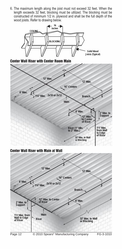
6. The maximum length along the joist must not exceed 32 feet. When the length exceeds 32 feet, blocking must be utilized. The blocking must be constructed of minimum 1/2 in. plywood and shall be the full depth of the wood joists. Refer to drawing below.
Center Wall Riser with Center Room Main
Center Wall Riser with Main at Wall
6' Max.
12' Max.
1¾" Max.
12' Max.
2x10 or 2x12
16" Centers
Branch
2' Max. to Support
1½' Max. from Wallto Edge of Riser
12" Max. to Center of Riser
32' Max. to Wall or Blocking
Riser (1" Min. to 2" Max.)
6' Max.
Main
6' Max.
12' Max.
1¾" Max.
12' Max.
2x10 or 2x12
16" Centers
Branch
2' Max. to Support
1½' Max. from Wall to Edge of Riser
12" Max. to Center of Riser
32' Max. to Wall or Blocking
Riser
6' Max.
Main
CEILING
16inches
Solid WoodJoists (Typical)
BLOCKING
FG-3-1010 © 2010 Spears® Manufacturing Company Page 13
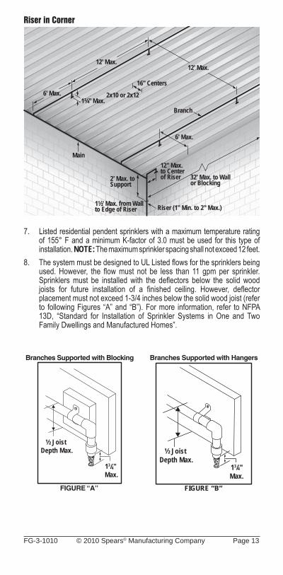
Riser in Corner
7. Listed residential pendent sprinklers with a maximum temperature rating of 155° F and a minimum K-factor of 3.0 must be used for this type of installation. NOTE: The maximum sprinkler spacing shall not exceed 12 feet.
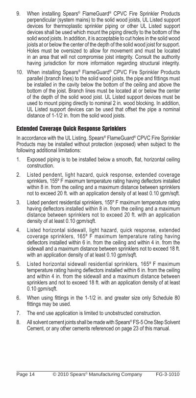
8. The system must be designed to UL Listed fl ows for the sprinklers being used. However, the fl ow must not be less than 11 gpm per sprinkler. Sprinklers must be installed with the defl ectors below the solid wood joists for future installation of a fi nished ceiling. However, defl ector placement must not exceed 1-3/4 inches below the solid wood joist (refer to following Figures “A” and “B”). For more information, refer to NFPA 13D, “Standard for Installation of Sprinkler Systems in One and Two Family Dwellings and Manufactured Homes”.
6' Max.
12' Max.
1¾" Max.
12' Max.
2x10 or 2x12
16" Centers
Branch
2' Max. to Support
1½' Max. from Wallto Edge of Riser
12" Max. to Center of Riser 32' Max. to Wall
or Blocking
Riser (1" Min. to 2" Max.)
6' Max.
Main
Branches Supported with Blocking
FIGURE “A”
½ Joist Depth Max.
13/4" Max.
Branches Supported with Hangers
FIGURE “B”
½ Joist Depth Max.
13/4"Max.
Page 14 © 2010 Spears® Manufacturing Company FG-3-1010
9. When installing Spears® FlameGuard® CPVC Fire Sprinkler Products perpendicular (system mains) to the solid wood joists, UL Listed support devices for thermoplastic sprinkler piping or other UL Listed support devices shall be used which mount the piping directly to the bottom of the solid wood joists. In addition, it is acceptable to cut holes in the solid wood joists at or below the center of the depth of the solid wood joist for support. Holes must be oversized to allow for movement and must be located in an area that will not compromise joist integrity. Consult the authority having jurisdiction for more information regarding structural integrity.
10. When installing Spears® FlameGuard® CPVC Fire Sprinkler Products parallel (branch lines) to the solid wood joists, the pipe and fi ttings must be installed in the cavity below the bottom of the ceiling and above the bottom of the joist. Branch lines must be located at or below the center of the depth of the solid wood joist. UL Listed support devices must be used to mount piping directly to nominal 2 in. wood blocking. In addition, UL Listed support devices can be used that offset the pipe a nominal distance of 1-1/2 in. from the solid wood joists.
Extended Coverage Quick Response SprinklersIn accordance with the UL Listing, Spears® FlameGuard® CPVC Fire Sprinkler Products may be installed without protection (exposed) when subject to the following additional limitations:1. Exposed piping is to be installed below a smooth, fl at, horizontal ceiling
construction.2. Listed pendent, light hazard, quick response, extended coverage
sprinklers, 155º F maximum temperature rating having defl ectors installed within 8 in. from the ceiling and a maximum distance between sprinklers not to exceed 20 ft. with an application density of at least 0.10 gpm/sqft.
3. Listed pendent residential sprinklers, 155º F maximum temperature rating having defl ectors installed within 8 in. from the ceiling and a maximum distance between sprinklers not to exceed 20 ft. with an application density of at least 0.10 gpm/sqft.
4. Listed horizontal sidewall, light hazard, quick response, extended coverage sprinklers, 165º F maximum temperature rating having defl ectors installed within 6 in. from the ceiling and within 4 in. from the sidewall and a maximum distance between sprinklers not to exceed 18 ft. with an application density of at least 0.10 gpm/sqft.
5. Listed horizontal sidewall residential sprinklers, 165º F maximum temperature rating having defl ectors installed within 6 in. from the ceiling and within 4 in. from the sidewall and a maximum distance between sprinklers and not to exceed 18 ft. with an application density of at least 0.10 gpm/sqft.
6. When using fi ttings in the 1-1/2 in. and greater size only Schedule 80 fi ttings may be used.
7. The end use application is limited to unobstructed construction.8. All solvent cement joints shall be made with Spears® FS-5 One Step Solvent
Cement, or any other cements referenced on page 23 of this manual.
FG-3-1010 © 2010 Spears® Manufacturing Company Page 15
Return Air Plenum InstallationSpears® FlameGuard® CPVC Fire Sprinkler Products meet the combustibility requirements for thermoplastic sprinkler pipe, as described in the Standard for Installation of Air Conditioning and Ventilating Systems, NFPA 90A.Spears® FlameGuard® CPVC Fire Sprinkler Products may be installed in the plenum space adjacent to, but not over, an opening in the ceiling, such as a ventilation grill.
Garage InstallationsSpears® FlameGuard® CPVC Fire Sprinkler Products are suitable for use in garages requiring sprinklers, as defi ned in NFPA 13R, with the following requirements:Minimum protection consisting of either one layer of 3/8-inch thick gypsum or 1/2-inch thick plywood must be provided.Listed pendent or sidewall sprinklers with a maximum temperature rating of 225° F (107° C) must be used.All sprinklers must be installed per the manufacturer’s published installation instructions.The system must be installed per the requirements of NFPA 13R and these installation instructions.
Ambient Temperature LimitationsSpears® FlameGuard® CPVC Fire Sprinkler Products are suitable for use in areas where ambient temperatures are within the range of 35° F (2° C) to 150° F (65° C). The Loss Prevention Certifi cation Board (LPCB) listing states the maximum ambient temperature shall not exceed 120° F (50° C).
High Temperature AreasSpears® FlameGuard® CPVC Fire Sprinkler Products can be installed in areas, such as an attic, where the ambient temperature exceeds 150° F (65° C) if ventilation is provided or if insulation is used around the product to maintain a cooler environment.
WARNING: DO NOT install Spears® FlameGuard® CPVC Fire Sprinkler Products in areas where the ambient temperature exceeds 150° F (65° C) without adequate ventilation or insulation around the product to maintain a cooler environment.
Cold Temperature AreasSpears® FlameGuard® CPVC Fire Sprinkler Products can be used in areas where the ambient temperature remains above 35° F (2° C). These products can also be used in an area subject to freezing temperatures if the sprinkler system installation is protected from freezing. Many standard cold weather piping design and installation practices can be used to protect the system from freezing, including, but not limited to the use of low pressure dry pipe and pre-action systems (see titled section in this manual), the use of glycerin, insulation installation techniques, and pipe insulation. Contact the manufacturers for compatibility of their products with Spears® FlameGuard® CPVC Fire Sprinkler Products.
Page 16 © 2010 Spears® Manufacturing Company FG-3-1010
NOTE: Attention must be given to local insulating techniques and codes that require a particular method. Since very cold weather will make Spears® FlameGuard® CPVC Fire Sprinkler Products more susceptible to damage, extra care should be taken to avoid rough handling or impact to these products.
WARNING: DO NOT allow a sprinkler system to freeze. A frozen system will deactivate and the pressures built up can cause the sprinkler heads to open or damage the pipe and fi ttings. Antifreeze solutions of water and USP or CP grade GLYCERIN are acceptable for use with Spears® FlameGuard® CPVC Fire Sprinkler Products. Refer to NFPA 13, NFPA 13R, NFPA 13D and consult the local authority having jurisdiction before using glycerin solutions in fi re sprinkler applications.
WARNING: DO NOT use glycol-based antifreeze solutions. Glycol solutions are not chemically compatible with the CPVC material and can cause damage to the CPVC Fire Sprinkler System.
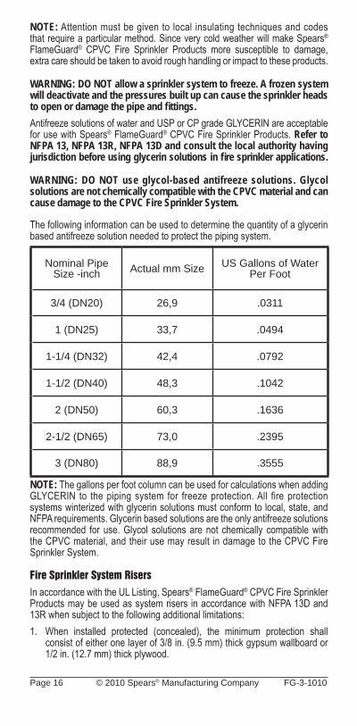
The following information can be used to determine the quantity of a glycerin based antifreeze solution needed to protect the piping system.
Nominal PipeSize -inch Actual mm Size US Gallons of Water
Per Foot
3/4 (DN20) 26,9 .0311
1 (DN25) 33,7 .0494
1-1/4 (DN32) 42,4 .0792
1-1/2 (DN40) 48,3 .1042
2 (DN50) 60,3 .1636
2-1/2 (DN65) 73,0 .2395
3 (DN80) 88,9 .3555
NOTE: The gallons per foot column can be used for calculations when adding GLYCERIN to the piping system for freeze protection. All fire protection systems winterized with glycerin solutions must conform to local, state, and NFPA requirements. Glycerin based solutions are the only antifreeze solutions recommended for use. Glycol solutions are not chemically compatible with the CPVC material, and their use may result in damage to the CPVC Fire Sprinkler System.
Fire Sprinkler System RisersIn accordance with the UL Listing, Spears® FlameGuard® CPVC Fire Sprinkler Products may be used as system risers in accordance with NFPA 13D and 13R when subject to the following additional limitations:1. When installed protected (concealed), the minimum protection shall
consist of either one layer of 3/8 in. (9.5 mm) thick gypsum wallboard or 1/2 in. (12.7 mm) thick plywood.
FG-3-1010 © 2010 Spears® Manufacturing Company Page 17
2. When installed without protection (exposed), the following limitations shall apply:a) The riser shall be installed below a smooth, fl at, horizontal ceiling
construction. A Listed residential pendent sprinkler is to be installed with its defl ector at the distance from the ceiling specifi ed in the sprinkler Listing.
OR The riser shall be installed below a horizontal unfi nished basement
ceiling (in accordance with NFPA 13D) constructed utilizing nominal 2 in. x 10 in. or nominal 2 in. x 12 in. exposed solid wood joists on 16 in. centers. A Listed residential pendent sprinkler is to be installed with its defl ector a maximum of 1-3/4 in. below the bottom of the solid wood joist in anticipation of future installation of a fi nished ceiling.
• When installing Spears® FlameGuard® CPVC Fire Sprinkler Products in conjunction with 2 in. x 12 in. solid wood joists, the maximum system working pressure under fl owing conditions shall not exceed 100 psi and the maximum system working pressure under static (nonflowing) conditions shall not exceed 175 psi.
b) The Listed residential pendent sprinkler is to have a maximum temperature rating of 155° F and a minimum K-factor of 3.0 and is to be installed at a maximum horizontal distance of 12 inches from the centerline of the riser. The system is to be designed based upon the Listed fl ows for the sprinkler being used. However, the fl ow must not be less than 11 gpm per sprinkler.
c) The riser shall be supported vertically within 2 feet of the ceiling or bottom of the joist.
d) The minimum riser diameter shall be 1 in. and the maximum riser diameter shall be 2 in.
e) The maximum distance between the wall(s) and the outside surface of the riser pipe shall be 1-1/2 in.
f) All solvent cement joints shall be made with Spears® FS-5, or any of the solvent cements referenced on page 23 of this manual.
g) These installations require the use of Schedule 80 fi ttings for riser sizes 1-1/2 in. and larger.
3. The system shall be installed per the requirements of NFPA 13, Sections 6-2.5 (2002 Edition), Support of Risers.
4. Spears® FlameGuard® CPVC Fire Sprinkler Products shall be installed per the manufacturer’s installation and design manual and this addendum.
5. Risers shall be supported by pipe clamps or by hangers located on the horizontal connection close to the riser. Only Listed hangers and clamps shall be used.
6. Vertical lines must be supported at intervals, described in 7 & 8 below, to avoid placing excessive load on a fi tting at the lower end. Do this by using riser clamps or double bolt pipe clamps Listed for this service. The clamps must not exert compressive stresses on the pipe. If possible, the clamps should be located just below a fi tting so that the shoulder of the fi tting rests against the clamp. If necessary, a coupling can be modifi ed and adhered to the pipe as a bearing support such that the shoulder of the fi tting rests on the clamp. Follow the manufacturer’s recommended cure time.
Page 18 © 2010 Spears® Manufacturing Company FG-3-1010
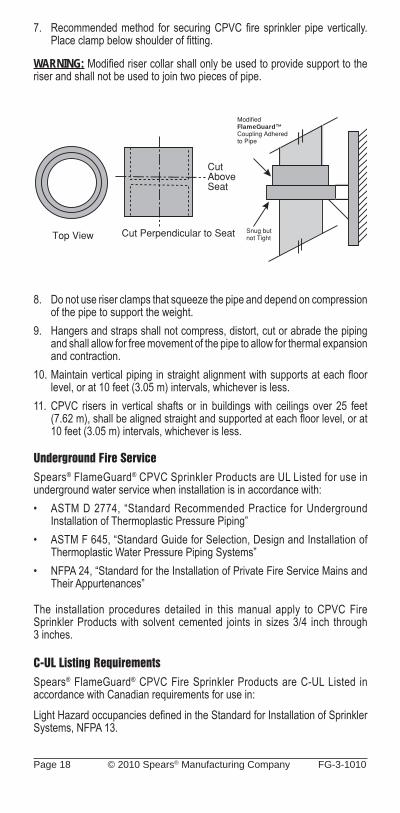
7. Recommended method for securing CPVC fi re sprinkler pipe vertically. Place clamp below shoulder of fi tting.
WARNING: Modifi ed riser collar shall only be used to provide support to the riser and shall not be used to join two pieces of pipe.
8. Do not use riser clamps that squeeze the pipe and depend on compression of the pipe to support the weight.
9. Hangers and straps shall not compress, distort, cut or abrade the piping and shall allow for free movement of the pipe to allow for thermal expansion and contraction.
10. Maintain vertical piping in straight alignment with supports at each fl oor level, or at 10 feet (3.05 m) intervals, whichever is less.
11. CPVC risers in vertical shafts or in buildings with ceilings over 25 feet (7.62 m), shall be aligned straight and supported at each fl oor level, or at 10 feet (3.05 m) intervals, whichever is less.
Underground Fire ServiceSpears® FlameGuard® CPVC Sprinkler Products are UL Listed for use in underground water service when installation is in accordance with:• ASTM D 2774, “Standard Recommended Practice for Underground
Installation of Thermoplastic Pressure Piping”• ASTM F 645, “Standard Guide for Selection, Design and Installation of
Thermoplastic Water Pressure Piping Systems”• NFPA 24, “Standard for the Installation of Private Fire Service Mains and
Their Appurtenances”
The installation procedures detailed in this manual apply to CPVC Fire Sprinkler Products with solvent cemented joints in sizes 3/4 inch through 3 inches.
C-UL Listing RequirementsSpears® FlameGuard® CPVC Fire Sprinkler Products are C-UL Listed in accordance with Canadian requirements for use in:Light Hazard occupancies defi ned in the Standard for Installation of Sprinkler Systems, NFPA 13.
FlameGuard™
FG-3-1010 © 2010 Spears® Manufacturing Company Page 19
Residential occupancies as defi ned in the Standard for Installation of Sprinkler Systems in Residential Occupancies up to Four Stories in Height, NFPA 13R.Residential occupancies as defi ned in the Standard for Installation of Sprinkler Systems in One and Two Family Dwelling and Manufactured Homes, NFPA 13D.
Protected InstallationsWhen used with standard response sprinklers, protection shall be provided for Spears® CPVC piping products by ceilings, walls or soffi ts consisting of the following minimum protection: lath and plaster, 9.5 mm thick gypsum wallboard, 13 mm thick plywood or a suspended membrane ceiling with lay-in panels or tiles, classifi ed with respect to surface burning characteristics having mass of not less than 1.7 kg/sq m and installed in steel suspension grids. The effectiveness of this protection can be impaired if penetrated by openings such as ventilation grills, exhaust fans connected to metal ducts serving washrooms excepted. Where such penetration is present, individual openings exceeding 0.03 sq m but not exceeding 0.71 sq m in an area must be located so that the distance from the edge of the opening to the nearest sprinkler does not exceed 300 mm. This piping shall not be used where such openings exceed 0.71 sq m in area. The effect of the presence of non-rated recessed lighting fi xtures, public address speakers and other interruptions of the protective membrane has not been investigated.
Exposed InstallationsAs an alternative to the protection requirements, Spears® FlameGuard® CPVC Fire Sprinkler Products may be installed without protection (exposed) when subject to the following additional limitations:
• Exposed piping is to be installed below a smooth, flat, horizontal, fixed ceiling construction.
• Listed Quick-Response pendent sprinklers having defl ectors installed within 8 inches from ceiling or Listed Residential pendent located in accordance with their Listing and a maximum distance between sprinklers not to exceed 15 feet.
• Listed Quick-Response horizontal sidewall sprinklers having deflectors installed within 6 inches from the ceiling and within 4 inches of the sidewall or Listed Residential horizontal sidewall sprinklers located in accordance with their Listing and a maximum distance between sprinklers not to exceed 14 feet.
During remodeling or repair, appropriate precautions shall be implemented to properly shield the piping from the protected occupancy.
Spears® FlameGuard® CPVC Fire Sprinkler Piping Products are to be installed in accordance with the requirements specified in NFPA 13, NFPA 13R or NFPA 13D and the National Building Code of Canada. Spears® FlameGuard® CPVC Fire Sprinkler Piping Products must be installed in accordance with the other special installation and design criteria relative to handling, assembly, pipe hanger spacing, piping and sprinkler restraint, sprinkler temperature rating, piping location, testing procedures, friction loss characteristics and other applicable requirements specifi ed in the manual. The use of Spears® FlameGuard® CPVC Fire Sprinkler Products in ceiling spaces above non-sprinklered areas has not been investigated.
Page 20 © 2010 Spears® Manufacturing Company FG-3-1010
Spears® FlameGuard® CPVC Fire Sprinkler Piping Products are Listed for use in wet pipe systems only, and are not Listed for outdoor use.
Spears® FlameGuard® CPVC Fire Sprinkler Products are C-UL Listed in accordance with Canadian requirements for use in combination with CPVC sprinkler products Listed in accordance with Canadian requirements and manufactured by Victaulic (pipe and fi ttings), Harvel (pipe), Ipex (pipe and fi ttings), TYCO Fire Products (pipe and fi ttings), Viking (pipe), or Nibco (fi ttings).
NOTICE: While Spears® FlameGuard® CPVC Fire Sprinkler Products are Listed for use in combination with other listed manufacturers’ products, specifi c application approvals may not be the same amongst manufacturers. It is the installer’s responsibility to verify suitability of products used in combination according to each manufacturer’s installation instructions. Contact Spears® if you have questions on any application not addressed.
Spears® recommends the use of FS-5 One Step Low VOC Solvent Cement. However, Victaulic 899; Ipex BM-5; Central Sprinkler CSC-500; Nibco FP-1000 and TYCO Fire Products TFP-500 CPVC Solvent Cements can also be used in place of the FS-5 One Step Low VOC Solvent Cement, provided that the assembly and curing information referenced within this manual is used.
Factory Mutual Approvals
Spears® FlameGuard® CPVC Fire Sprinkler Products have been approved by Factory Mutual for use in exposed environments in Light Hazard Occupancies as defi ned in:
NFPA 13, the Standard for “Installation of Sprinkler Systems.”
Residential occupancies, as defi ned in NFPA 13R, the Standard for “Installation of Sprinkler Systems in Residential Occupancies up to and Including Four Stories in Height.”
Residential occupancies, as defi ned in NFPA 13D, the Standard for “Installation of Sprinkler Systems in One and Two Family Dwellings and Manufactured Homes.”
Spears® FlameGuard® CPVC Fire Sprinkler Products are FM Approved for use with Fire Resistant Barriers for CPVC Pipe and Fittings in Light Hazard Occupancies under FM Approval of the Soffi -Steel™ System manufactured by Grice Engineering, Inc. Installation is to be made in accordance with the FM Approval requirements for the Soffi -Steel™ System.
Loss Prevention Certifi cation Board LPCB
Spears® FlameGuard® CPVC Fire Sprinkler Products are approved for use as agreed between plastics suppliers, purchaser/installer, authority having jurisdiction and/or insurer in accordance with documented supplier Installation Instructions but subject to the following criteria taking precedence:
FG-3-1010 © 2010 Spears® Manufacturing Company Page 21
• Use of plastic pipe and fi ttings is subject to water authority agreement for the territory concerned.
• LPCB Approved quick response sprinklers shall be used with exposed (i.e., fi re exposure) plastic pipe and fi ttings.
• Plastic pipe and fi ttings are suitable for use only with wet pipe systems.• Care should be exercised to ensure that joints are adequately cured,
in accordance with the manufacturer’s installation instructions prior to pressurization.
• Plastic pipe and fi ttings shall not be installed outdoors.• Where plastic pipe and fi ttings are exposed (i.e., fi re exposure), the system
shall be installed close to a fl at ceiling construction.• Sprinkler systems which employ plastic pipe and fi ttings shall be designed
where possible to ensure no “no fl ow” sections of pipework in the event of sprinkler operation.
In addition, the maximum normal ambient temperature shall not exceed 120° F (50° C). The product shall only be installed in the UK by LPCB Certifi cated or Registered installing companies or by fi rms outside the UK who can provide evidence of personnel training in the installation of the product.
NSF® International
Spears® FlameGuard® CPVC Fire Sprinkler Products have been approved by NSF® for potable water applications. These products meet all applicable performance standards for a pressure rated application, as required in ANSI/NSF® Standard 14, and they comply with ANSI/NSF® Standard 61 for health effects. Spears® FlameGuard® CPVC Fire Sprinkler Products are tested against ASTM Standards F 438 and F 439. Penetrating Fire-rated Walls & PartitionsBefore beginning, consult the building codes and authorities having jurisdiction in your area. Several UL Classifi ed, through-penetration fi restop systems are approved for use with CPVC pipe. Consult the UL Building Materials Directory, the UL Fire Resistance Directory, and the system manufacturer for proper selection and application. Two manufacturers of Listed systems for use with CPVC pipe are Nelson Fire Stop Products (800-331-7325) and Tremco (800-321-7906). Consult Spears® Manufacturing Company for further information.
Heat Sources & Open Ceiling AreasPiping systems using Spears® FlameGuard® CPVC Fire Sprinkler Products must be laid out so that the piping is not closely exposed to heat producing sources, such as light fi xtures, ballasts, and steam lines. Pipe must not be positioned directly over open ventilation grills. During remodeling or ceiling repair, appropriate precautions must be implemented to properly protect the piping.
Page 22 © 2010 Spears® Manufacturing Company FG-3-1010
Use With Other Manufacturers’ Pipes, Fittings, & Solvent CementsSpears® FlameGuard® CPVC Fire Sprinkler Products may be used only in connection with UL, FM and NSF® certified CPVC products of other manufacturers. Use of Spears® FlameGuard® CPVC Fire Sprinkler Products in connection with CPVC products of other manufacturers which are not UL, FM and NSF® certifi ed may result in inappropriate product application and inconsistent determinations in the event of warranty claims.Spears® FlameGuard® CPVC Fire Sprinkler Products are UL Listed for use in combination with UL Listed CPVC sprinkler products manufactured by Victaulic (pipe and fi ttings), Harvel (pipe), Ipex (pipe and fi ttings), TYCO Fire Products (pipe and fi ttings), Viking (pipe), or Nibco (fi ttings).NOTICE: While Spears® FlameGuard® CPVC Fire Sprinkler Products are UL Listed for use in combination with other listed manufacturers’ products, specifi c application approvals may not be the same amongst manufacturers. It is the installer’s responsibility to verify suitability of products used in combination according to each manufacturer’s installation instructions. Contact Spears® if you have questions on any application not addressed in this manual.Spears® recommends the use of FS-5 One Step Low VOC Solvent Cement. However, Victaulic 899; Ipex BM-5; Central Sprinkler CSC-500; Nibco FP-1000 and TYCO Fire Products TFP-500 CPVC Solvent Cements can also be used in place of the FS-5 One Step Low VOC Solvent Cement, provided that the assembly and curing information referenced within this manual is used.
Installation & JoiningMake sure you follow all assembly and curing information referenced within this manual when installing Spears® FlameGuard® CPVC Fire Sprinkler Products. Failure to follow this instruction could cause improper curing, resulting in serious personal injury, signifi cant property damage, joint leakage, or joint failure.Before assembling any Spears® FlameGuard® CPVC Fire Sprinkler Products, you must inspect all components for cuts, scratches, gouges, split ends, or any other irregularities that have occurred during shipping and handling.
Solvent Cement Welded Joints STEP 1 Cut Pipe Square.CPVC pipe can be easily cut with a ratchet cutter, a wheel-type plastic tubing cutter, a power saw or a fi ne toothed saw. Tools used to cut CPVC must be designed for plastic use and must be in good condition in accordance with the tool manufacturer’s recommendations. It is important to cut the pipe square. A square cut provides the surface of the pipe with maximum bonding area.If any indication of damage or cracking is evident at the pipe end, cut off at least 2 inches (50 mm) beyond any visible crack.Notice: Avoid splitting the pipe when using ratchet cutters. Failure to do so may result in pipe failure or leakage.• Only use ratchet cutters that contain a sharp blade (blades dull quickly).• Only use ratchet cutters at temperatures of 50° F (10° C) or warmer.• Only use well-maintained, good quality ratchet cutters capable of consistently cutting the pipe squarely.
FG-3-1010 © 2010 Spears® Manufacturing Company Page 23
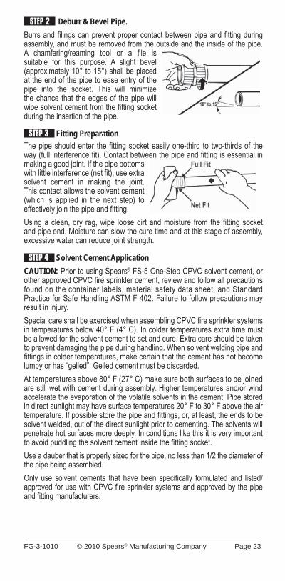
STEP 2 Deburr & Bevel Pipe.Burrs and fi lings can prevent proper contact between pipe and fi tting during assembly, and must be removed from the outside and the inside of the pipe. A chamfering/reaming tool or a fi le is suitable for this purpose. A slight bevel (approximately 10° to 15°) shall be placed at the end of the pipe to ease entry of the pipe into the socket. This will minimize the chance that the edges of the pipe will wipe solvent cement from the fi tting socket during the insertion of the pipe.
STEP 3 Fitting PreparationThe pipe should enter the fi tting socket easily one-third to two-thirds of the way (full interference fi t). Contact between the pipe and fi tting is essential in making a good joint. If the pipe bottoms with little interference (net fi t), use extra solvent cement in making the joint. This contact allows the solvent cement (which is applied in the next step) to effectively join the pipe and fi tting. Using a clean, dry rag, wipe loose dirt and moisture from the fi tting socket and pipe end. Moisture can slow the cure time and at this stage of assembly, excessive water can reduce joint strength.
STEP 4 Solvent Cement ApplicationCAUTION: Prior to using Spears® FS-5 One-Step CPVC solvent cement, or other approved CPVC fi re sprinkler cement, review and follow all precautions found on the container labels, material safety data sheet, and Standard Practice for Safe Handling ASTM F 402. Failure to follow precautions may result in injury.Special care shall be exercised when assembling CPVC fi re sprinkler systems in temperatures below 40° F (4° C). In colder temperatures extra time must be allowed for the solvent cement to set and cure. Extra care should be taken to prevent damaging the pipe during handling. When solvent welding pipe and fi ttings in colder temperatures, make certain that the cement has not become lumpy or has “gelled”. Gelled cement must be discarded.At temperatures above 80° F (27° C) make sure both surfaces to be joined are still wet with cement during assembly. Higher temperatures and/or wind accelerate the evaporation of the volatile solvents in the cement. Pipe stored in direct sunlight may have surface temperatures 20° F to 30° F above the air temperature. If possible store the pipe and fi ttings, or, at least, the ends to be solvent welded, out of the direct sunlight prior to cementing. The solvents will penetrate hot surfaces more deeply. In conditions like this it is very important to avoid puddling the solvent cement inside the fi tting socket.Use a dauber that is properly sized for the pipe, no less than 1/2 the diameter of the pipe being assembled.Only use solvent cements that have been specifi cally formulated and listed/approved for use with CPVC fi re sprinkler systems and approved by the pipe and fi tting manufacturers.
Page 24 © 2010 Spears® Manufacturing Company FG-3-1010
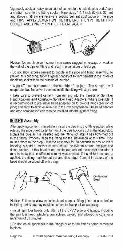
Vigorously apply a heavy, even coat of cement to the outside pipe end. Apply a medium coat to the fitting socket. Pipe sizes 1-1/4 inch (DN32, 32mm) and above shall always receive a second cement application on the pipe end. FIRST APPLY CEMENT ON THE PIPE END, THEN IN THE FITTING SOCKET, AND, FINALLY, ON THE PIPE END AGAIN.
Notice: Too much solvent cement can cause clogged waterways or weaken the wall of the pipe or fi tting and result in pipe failure or leakage.• Do not allow excess cement to puddle in the pipe and fi tting assembly. To prevent this puddling, apply a lighter coating of solvent cement to the inside of the fi tting socket than the outside of the pipe.• Wipe off excess cement on the outside of the joint. The solvents will evaporate, but the solvent cement inside the fi tting will stay there. • Take care to prevent cement from running into the threads of Sprinkler Head Adapters and Adjustable Sprinkler Head Adapters. Where possible, it is recommended to pre-install head adapters on to pre-cut Drops (section of pipe) and allow to achieve initial set in the inverted position. The head adapter and drop combination can then be installed into the system fi tting.
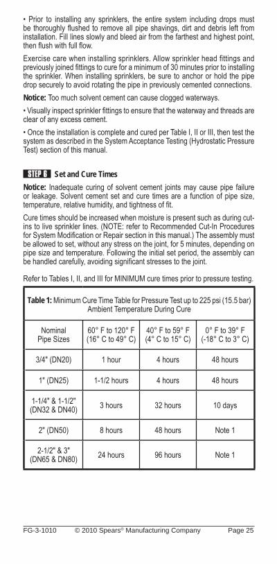
STEP 5 Assembly After applying cement, immediately insert the pipe into the fi tting socket, while rotating the pipe one-quarter turn until the pipe bottoms out at the fi tting stop. Rotate the pipe as it is inserted into the fi tting not after it has bottomed out in the fi tting. Properly align the fi tting for the installation at this time. Pipe must bottom to the stop. Hold the assembly for 30 seconds to ensure initial bonding. A bead of solvent cement should be evident around the pipe and fi tting juncture. If this bead is not continuous around the socket shoulder, it may indicate that insuffi cient cement was applied. If insuffi cient cement is applied, the fi tting must be cut out and discarded. Cement in excess of the bead should be wiped off with a rag.
Notice: Failure to allow sprinkler head adapter fi tting joints to cure before installing sprinklers may result in cement in the sprinkler waterway.• Install sprinkler heads only after all the CPVC pipe and fi ttings, including the sprinkler head adapters, are solvent welded and allowed to cure for a minimum of 30 minutes.• Do not install sprinklers in the fi ttings prior to the fi ttings being cemented in place.
FG-3-1010 © 2010 Spears® Manufacturing Company Page 25
• Prior to installing any sprinklers, the entire system including drops must be thoroughly fl ushed to remove all pipe shavings, dirt and debris left from installation. Fill lines slowly and bleed air from the farthest and highest point, then fl ush with full fl ow.Exercise care when installing sprinklers. Allow sprinkler head fittings and previously joined fi ttings to cure for a minimum of 30 minutes prior to installing the sprinkler. When installing sprinklers, be sure to anchor or hold the pipe drop securely to avoid rotating the pipe in previously cemented connections.Notice: Too much solvent cement can cause clogged waterways.• Visually inspect sprinkler fi ttings to ensure that the waterway and threads are clear of any excess cement.• Once the installation is complete and cured per Table I, II or III, then test the system as described in the System Acceptance Testing (Hydrostatic Pressure Test) section of this manual.
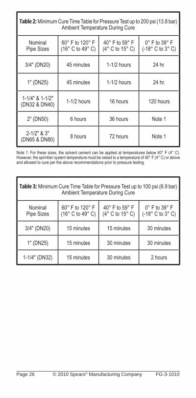
STEP 6 Set and Cure Times Notice: Inadequate curing of solvent cement joints may cause pipe failure or leakage. Solvent cement set and cure times are a function of pipe size, temperature, relative humidity, and tightness of fi t.Cure times should be increased when moisture is present such as during cut-ins to live sprinkler lines. (NOTE: refer to Recommended Cut-In Procedures for System Modifi cation or Repair section in this manual.) The assembly must be allowed to set, without any stress on the joint, for 5 minutes, depending on pipe size and temperature. Following the initial set period, the assembly can be handled carefully, avoiding signifi cant stresses to the joint.
Refer to Tables I, II, and III for MINIMUM cure times prior to pressure testing.
Table 1: Minimum Cure Time Table for Pressure Test up to 225 psi (15.5 bar) Ambient Temperature During Cure
Nominal Pipe Sizes
60° F to 120° F(16° C to 49° C)
40° F to 59° F(4° C to 15° C)
0° F to 39° F(-18° C to 3° C)
3/4" (DN20) 1 hour 4 hours 48 hours
1" (DN25) 1-1/2 hours 4 hours 48 hours
1-1/4" & 1-1/2"(DN32 & DN40) 3 hours 32 hours 10 days
2" (DN50) 8 hours 48 hours Note 1
2-1/2" & 3"(DN65 & DN80) 24 hours 96 hours Note 1
Page 26 © 2010 Spears® Manufacturing Company FG-3-1010
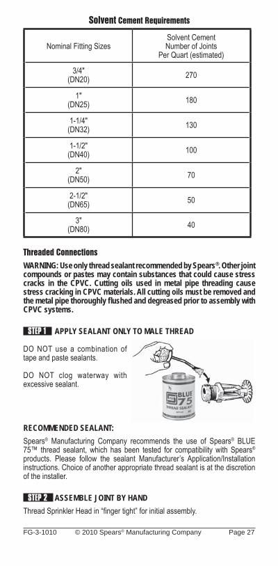
Table 2: Minimum Cure Time Table for Pressure Test up to 200 psi (13.8 bar)Ambient Temperature During Cure
Nominal Pipe Sizes
60° F to 120° F(16° C to 49° C)
40° F to 59° F(4° C to 15° C)
0° F to 39° F(-18° C to 3° C)
3/4" (DN20) 45 minutes 1-1/2 hours 24 hr.
1" (DN25) 45 minutes 1-1/2 hours 24 hr.
1-1/4" & 1-1/2"(DN32 & DN40) 1-1/2 hours 16 hours 120 hours
2" (DN50) 6 hours 36 hours Note 1
2-1/2" & 3"(DN65 & DN80) 8 hours 72 hours Note 1
Note 1: For these sizes, the solvent cement can be applied at temperatures below 40° F (4° C).However, the sprinkler system temperature must be raised to a temperature of 40° F (4° C) or above and allowed to cure per the above recommendations prior to pressure testing.
Table 3: Minimum Cure Time Table for Pressure Test up to 100 psi (6.9 bar) Ambient Temperature During Cure
Nominal Pipe Sizes
60° F to 120° F(16° C to 49° C)
40° F to 59° F(4° C to 15° C)
0° F to 39° F(-18° C to 3° C)
3/4" (DN20) 15 minutes 15 minutes 30 minutes
1" (DN25) 15 minutes 30 minutes 30 minutes
1-1/4" (DN32) 15 minutes 30 minutes 2 hours
FG-3-1010 © 2010 Spears® Manufacturing Company Page 27
Solvent Cement Requirements
Nominal Fitting SizesSolvent CementNumber of Joints
Per Quart (estimated)
3/4"(DN20) 270
1"(DN25) 180
1-1/4"(DN32) 130
1-1/2"(DN40) 100
2"(DN50) 70
2-1/2"(DN65) 50
3"(DN80) 40
Threaded ConnectionsWARNING: Use only thread sealant recommended by Spears®. Other joint compounds or pastes may contain substances that could cause stress cracks in the CPVC. Cutting oils used in metal pipe threading cause stress cracking in CPVC materials. All cutting oils must be removed and the metal pipe thoroughly fl ushed and degreased prior to assembly with CPVC systems.
STEP 1 APPLY SEALANT ONLY TO MALE THREAD
DO NOT use a combination of tape and paste sealants.
DO NOT clog waterway with excessive sealant.
RECOMMENDED SEALANT:Spears® Manufacturing Company recommends the use of Spears® BLUE 75™ thread sealant, which has been tested for compatibility with Spears® products. Please follow the sealant Manufacturer’s Application/Installation instructions. Choice of another appropriate thread sealant is at the discretion of the installer.
STEP 2 ASSEMBLE JOINT BY HANDThread Sprinkler Head in “fi nger tight” for initial assembly.
Page 28 © 2010 Spears® Manufacturing Company FG-3-1010
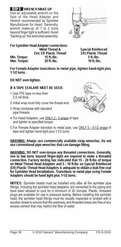
STEP 3 WRENCH MAKE-UPUse an adjustable wrench on the flats of the Head Adapter and Wrench recommended by Sprinkler Manufacturer for Head. Generally, wrench make-up of 1 to 2 turns beyond fi nger tight is suffi cient. Avoid “backing up” the wrenched assembly.
For Sprinkler Head Adapter connections: Metal Thread & Special Reinforced Zinc SR Plastic Thread SR) Plastic ThreadMin. Torque: 15 ft.-lbs. 5 ft.-lbs.Max. Torque: 20 ft.-lbs. 10 ft.-lbs.
For Female Adapter transitions to metal pipe, tighten hand-tight plus 1-1/2 turns.
DO NOT over-tighten.
IF A TAPE SEALANT MUST BE USED:1. Use TFE tape no less than 2.5 mil thick.2. Initial wrap must fully cover the thread end.3. Wrap clockwise with standard pipe threads.4. For Head Adapters, use ONLY 2 - 3 wraps of tape and tighten to specifi ed torque.5. For Female Adapter transition to metal pipe, use ONLY 5 - 5-1/2 wraps of
tape and tighten hand-tight plus 1-1/2 turns.
WARNING: Always use commercially available strap wrenches. Do not use conventional pipe wrenches that can damage fi tting.
WARNING: DO NOT over-torque any threaded connections. Generally, one to two turns beyond fi nger-tight are required to make a threaded connection. Factory testing has indicated that 15 - 20 ft-lbs of torque on Metal Thread Head Adapters and 5 - 10 ft-lbs on Special Reinforced (SR) Plastic Thread Head Adapters is adequate to obtain a leak free seal for Sprinkler Head Installations. Transitions to metal pipe using Female Adapters should be hand tight plus 1-1/2 turns.
NOTICE: Sprinkler heads must be installed only after all fi re sprinkler pipe fi ttings, including the sprinkler head adapters, are cemented to the piping and have been allowed to cure for a minimum of 30 minutes. Plastic, threaded plugs are available for use in pressure testing. Before installing the sprinkler head, the sprinkler head fi ttings must be visually inspected or probed with a wooden dowel to ensure that the waterway and threaded areas are free of any excess cement that may restrict the fl ow of water.
FG-3-1010 © 2010 Spears® Manufacturing Company Page 29
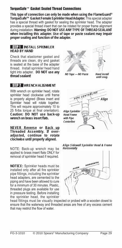
TorqueSafe™ Gasket Sealed Thread Connections This type of connection can only be made when using the FlameGuard® TorqueSafe™ Gasket Female Sprinkler Head Adapter. This special adapter has a special thread with gasket for sealing the sprinkler head. The adapter provides a special thread insert that can be rotated for proper frame alignment during installation. Warning: DO NOT USE ANY TYPE OF THREAD SEALANT when installing this adapter. Use of tape or paste sealant may impair proper sealing and function of the adapter.
STEP 1 INSTALL SPRINKLER HEAD BY HANDCheck that elastomer gasket and threads are clean, dry and gasket is seated at the base of the adapter thread. Install sprinkler head hand tight into adapter. DO NOT use any thread sealant!
STEP 2 WRENCH ALIGNMENTWith wrench on sprinkler head, rotate sprinkler head clockwise until frame is properly aligned (Brass insert and Sprinkler head will rotate together. This will require approximately 10 to 25 ft-lbs torque at fi nal orientation). Caution: DO NOT use back-up wrench on brass insert fl ats.
NEVER Reverse or Back up Threaded Assembly. If over-adjusted, continue to rotate clockwise until properly aligned.
NOTE: Back-up wrench may be applied to brass insert fl ats ONLY for removal of sprinkler head if required.
NOTICE: Sprinkler heads must be installed only after all fire sprinkler pipe fittings, including the sprinkler head adapters, are cemented to the piping and have been allowed to cure for a minimum of 30 minutes. Plastic, threaded plugs are available for use in pressure testing. Before installing the sprinkler head, the sprinkler head fittings must be visually inspected or probed with a wooden dowel to ensure that the waterway and threaded areas are free of any excess cement that may restrict the fl ow of water.
Align
Align Sprinkler Head Frame with Pipe Centerline
NO Tape — NO Paste Hand install until snug.
Align Sidewall Sprinkler Head & Frame Horizontally
Page 30 © 2010 Spears® Manufacturing Company FG-3-1010
Painting Pipe & FittingsCAUTION: The UL Listing DOES NOT cover painted CPVC fire sprinkler piping products. Use of certain paints, such as oil-based, can damage CPVC fi re sprinkler piping products. Before painting any CPVC fi re sprinkler piping products, you must consult with your local authority having jurisdiction for restrictions.
Cleaning Spears® FlameGuard® CPVC Fire Sprinkler Products can be cleaned using a mild soap and water solution. DO NOT use ammonia or other harsh chemical cleaners.
Transitions to Other MaterialsSpecifi cally designed female threaded adapters, grooved coupling adapters, and flanges are Listed for connecting systems incorporating Spears® FlameGuard® CPVC Fire Sprinkler Products to other materials, valves, and accessories. A special, reinforced female threaded adapter is available for connection to the sprinkler head.
Flanged ConnectionsPiping runs joined to the fl anges must be installed in a straight line in relation to the fl ange to avoid stress at the fl ange due to misalignment. In addition, piping must be secured and supported to prevent lateral movement, which can create stress and damage the flange. Use only full-faced, Grade E, EPDM, 1/8" thick fl ange gaskets.
STEP 1 Attach Flange to Pipe. The fl ange must be attached to UL Listed CPVC pipe following procedures for Solvent Cement Welded Joints in this manual.
NOTICE: When using “One-Piece” type fl anges (fi xed fl ange ring), care must be taken to align bolt holes with mating fl ange during solvent welding installation to pipe, or assure that pipe in system can be adequately rotated for correct hole alignment.
STEP 2 Position Gasket & Align Flanges. With gasket between fl anges, align gasket and mating fl ange bolt holes by rotating fl ange ring (see notice above).
STEP 3 Install Bolts, Nuts, & Washers. Bolts should be lubricated with an acceptable anti-seize lubricant (such as IMS Copper Flake). Insert required bolts through fl ange bolt holes being sure to use two (2) fl at washers per bolt, one at head and one below nut. Make sure that mating fl anges are fl ush against gasket and properly aligned. Tighten nuts by hand until snug.
WARNING: Certain lubricants can cause stress cracking in CPVC materials.
STEP 4 Tighten Flange Bolts. Establish uniform pressure over the flange face by tightening bolts in 5-ft. lbs. increments using the sequence shown in Figure 1 and specified torque values.
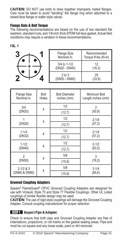
FG-3-1010 © 2010 Spears® Manufacturing Company Page 31
CAUTION: DO NOT use bolts to draw together improperly mated fl anges. Care must be taken to avoid “bending” the fl ange ring when attached to a raised-face fl ange or wafer style valves.
Flange Data & Bolt TorqueThe following recommendations are based on the use of two standard fl at washers, standard nuts, and 1/8-inch thick EPDM full-face gasket. Actual fi eld conditions may require a variation in these recommendations.
FIG. 1
Flange SizeNominal In.
RecommendedTorque ft-lbs (N-m)
3/4 to 1-1/2(DN20 - DN40)
12(16,3)
2 to 3(DN50 - DN80)
25(33,9)
Flange SizeNominal in.
BoltHoles
Bolt Diameterinches (mm)
Minimum BoltLength inches (mm)
3/4(DN20) 4
1/2 2(50,8)(12,7)
1(DN25) 4
1/2 2-1/4(57,2)(12,7)
1-1/4(DN32) 4
1/2 2-1/4(57,2)(12,7)
1-1/2(DN40) 4
1/2 2-1/2(63,5)(12,7)
2(DN50) 4
5/8 3(76,2)(15,9)
2-1/2 & 3(DN65 & DN80) 4
5/8 3-1/4(85,6)(15,9)
Grooved Coupling AdaptersSpears® FlameGuard® CPVC Grooved Coupling Adapters are designed for use with Victaulic Style 75 and Style 77 Flexible Couplings. Other UL Listed couplings of similar fl exible design may be used.CAUTION: The use of rigid style couplings will damage the Grooved Coupling Adapter. Consult coupling manufacturer for proper selection.
STEP 1 Inspect Pipe & Adapter.Check to ensure that both pipe and Grooved Coupling Adapter are free of indentations, projections, or roll marks on the gasket seating areas. Pipe end must be cut square and any loose scale, paint or dirt removed.
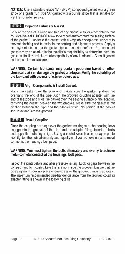
Page 32 © 2010 Spears® Manufacturing Company FG-3-1010
NOTICE: Use a standard grade “E” (EPDM) compound gasket with a green stripe or a grade “E,” type “A” gasket with a purple stripe that is suitable for wet fi re sprinkler service.
STEP 2 Inspect & Lubricate Gasket. Be sure the gasket is clean and free of any cracks, cuts, or other defects that could cause leaks. DO NOT allow solvent cement to contact the sealing surface of the gasket. Lubricate the gasket with a vegetable soap-base lubricant to prevent pinching and to assist in the seating and alignment process. Apply a thin layer of lubricant to the gasket lips and exterior surface. Pre-lubricated gaskets may be used. It is the installer’s responsibility to determine both the gasket suitability and chemical compatibility of any lubricants. Consult gasket and lubricant manufacturers.
WARNING: Certain lubricants may contain petroleum based or other chemical that can damage the gasket or adapter. Verify the suitability of the lubricant with the manufacturer before use.
STEP 3 Align Components & Install Gasket. Place the gasket over the pipe end making sure the gasket lip does not overhang the end of the pipe. Align the grooved coupling adapter with the end of the pipe and slide the gasket over the seating surface of the adapter, centering the gasket between the two grooves. Make sure the gasket is not pinched between the pipe and the adapter fi tting. No portion of the gasket should extend into the grooves.
STEP 4 Install Coupling.Place the coupling housings over the gasket, making sure the housing keys engage into the grooves of the pipe and the adapter fi tting. Insert the bolts and apply the nuts fi nger-tight. Using a socket wrench or other appropriate tool, tighten the nuts alternately and equally until you achieve metal-to-metal contact at the housings’ bolt pads.
WARNING: You must tighten the bolts alternately and evenly to achieve metal-to-metal contact at the housings’ bolt pads.
Inspect the joints before and after pressure testing. Look for gaps between the bolt pads and for housing keys that are not inside the grooves. Ensure that the pipe alignment does not place undue stress on the grooved coupling adapters. The maximum recommended pipe hanger distance from the grooved coupling adapter fi tting is shown in the following table.
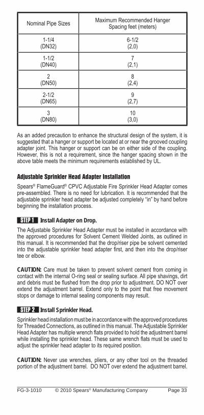
FG-3-1010 © 2010 Spears® Manufacturing Company Page 33
Nominal Pipe Sizes Maximum Recommended HangerSpacing feet (meters)
1-1/4(DN32)
6-1/2(2,0)
1-1/2(DN40)
7(2,1)
2(DN50)
8(2,4)
2-1/2(DN65)
9(2,7)
3(DN80)
10(3,0)
As an added precaution to enhance the structural design of the system, it is suggested that a hanger or support be located at or near the grooved coupling adapter joint. This hanger or support can be on either side of the coupling. However, this is not a requirement, since the hanger spacing shown in the above table meets the minimum requirements established by UL.
Adjustable Sprinkler Head Adapter InstallationSpears® FlameGuard® CPVC Adjustable Fire Sprinkler Head Adapter comes pre-assembled. There is no need for lubrication. It is recommended that the adjustable sprinkler head adapter be adjusted completely “in” by hand before beginning the installation process.
STEP 1 Install Adapter on Drop. The Adjustable Sprinkler Head Adapter must be installed in accordance with the approved procedures for Solvent Cement Welded Joints, as outlined in this manual. It is recommended that the drop/riser pipe be solvent cemented into the adjustable sprinkler head adapter fi rst, and then into the drop/riser tee or elbow.
CAUTION: Care must be taken to prevent solvent cement from coming in contact with the internal O-ring seal or sealing surface. All pipe shavings, dirt and debris must be fl ushed from the drop prior to adjustment. DO NOT over extend the adjustment barrel. Extend only to the point that free movement stops or damage to internal sealing components may result.
STEP 2 Install Sprinkler Head.Sprinkler head installation must be in accordance with the approved procedures for Threaded Connections, as outlined in this manual. The Adjustable Sprinkler Head Adapter has multiple wrench fl ats provided to hold the adjustment barrel while installing the sprinkler head. These same wrench fl ats must be used to adjust the sprinkler head adapter to its required position.
CAUTION: Never use wrenches, pliers, or any other tool on the threaded portion of the adjustment barrel. DO NOT over extend the adjustment barrel.
Page 34 © 2010 Spears® Manufacturing Company FG-3-1010
STEP 3 Adjust Finished Height. The maximum range of travel is 1-5/8". Always use multiple wrench fl ats for making adjustments. Make adjustments slowly if system is pressurized in order to avoid inadvertently over extending adjustment barrel.CAUTION: Care must be taken not to extend or retract the adjustment barrel excessively, since this may result in damage to the adapter. Adjust only to the point that free movement stops.For the purpose of hydraulic calculations, the adjustable sprinkler head equivalent length of pipe in feet are as follows: 3/4"x1/2" = 6-ft., 1"x1/2" = 9-ft.
Flushing SystemPrior to installing any sprinklers and testing, the entire system including drops must be thoroughly fl ushed to remove all pipe shavings, dirt and debris left from installation. Fill lines slowly and bleed air from the farthest and highest point, then fl ush with full fl ow.
System Acceptance Testing (Hydrostatic Pressure Test) Once an installation is completed and joints are properly cured per the above recommendations, the system should be hydrostatically pressure tested with water at 200 psi (13.8 bar) for 2 hours. See Table II for curing conditions at 200 psi (13.8 bar). The system should be pressure tested with water at 50 psi (3.4 bar) in excess of maximum pressure when the maximum system pressure is to be maintained in excess of 150 psi (10.3 bar). See Table I for curing conditions at 225 psi (15.5 bar). This requirement is in accordance with the requirements established by NFPA Standard 13, Section 24.2.1 (2007 Edition). Sprinkler systems in one- and two-family dwellings and mobile homes may be pressure tested with water at line pressure, after following Table III curing conditions, in accordance with the requirements established by NFPA 13D, Section 4.3 (2007 Edition).Prior to testing, be sure that the entire system including drops has been thoroughly fl ushed to remove all pipe shavings, dirt and debris left from installation as specifi ed in the preceding section.When pressure testing, the sprinkler system shall be slowly fi lled with water and the air bled from the highest and farthest sprinkler heads before pressure testing is applied. Air must be removed from piping systems (plastic or metal) to prevent it from being locked in the system when pressure is applied. Entrapped air can generate excessive surge pressures that can result in bodily injury and/or property damage, regardless of the piping materials used. If a leak is found, the fi tting must be cut out and discarded. A new section can be installed using couplings or a union. Unions should be used in accessible areas only.
FG-3-1010 © 2010 Spears® Manufacturing Company Page 35
Recommended Cut-in Procedures for System Modifi cation or RepairExisting system modifications or repairs can be made using Spears® FlameGuard® CPVC Fire Sprinkler Products. In order to maintain full system integrity, the following procedure must be followed when making a system tie-in or repair by cutting into an existing system line. A careful review of all Joining Procedures must be made prior to making a cut-in on an existing system and the Minimum Cut-in Cure Times schedule listed below must be followed. A variety of fi tting combinations can be used to tie into an existing system or replace a section between fi xed cut-in points. These include using a socket Tee for add-ons or a socket Coupling for repairs in combination with a mechanical joint such as a union grooved coupling adapter, or fl ange. Regardless of the components selected, the following must be adhered to:
STEP 1 System modifi cation cut-ins should be made on the smallest diameter pipe section, in close proximity to the area of modification, capable of properly supplying the system change.
STEP 2 Carefully plan and measure prior to cutting into existing system. Be sure to provide adequate space and insure that full insertion into fi tting sockets can be made during assembly.
Note: Allowance must be made for making a 1/4-turn twist when inserting the pipe into the fi tting during assembly of the tee (or other component), especially on 1-1/2" and larger pipe sizes. This may require assembly of components in combination with the cut-in tee to create a short spool piece for fi nal connection using socket unions, fl anges, or grooved coupling adapters.
STEP 3 Review all Installation & Joining procedures prior to commencing cut-in (including square cutting, deburring & beveling, cleaning, dry fi t checks).
STEP 4 Depressurize and drain existing line prior to making the cut-in.
STEP 5 Connect to the existing system prior to proceeding with the modifi cation or repair.
STEP 6 All pipe shavings, dirt, debris must be removed from the cut-in system and, water and residual moisture must be removed from all solvent cement areas. Vacuum lines and wipe dry with a clean dry rag. Moisture and dirt will slow the curing and can affect joint strength.
STEP 7 Use only a new can of approved solvent cement when making cut-in connections. Verify cement expiration date on can prior to use.
STEP 8 Cut-ins for modifi cations or system repairs are often made under less than ideal situations as compared to new installations. As a result, the following specifi ed Minimum Cut-in Cure times must be used.
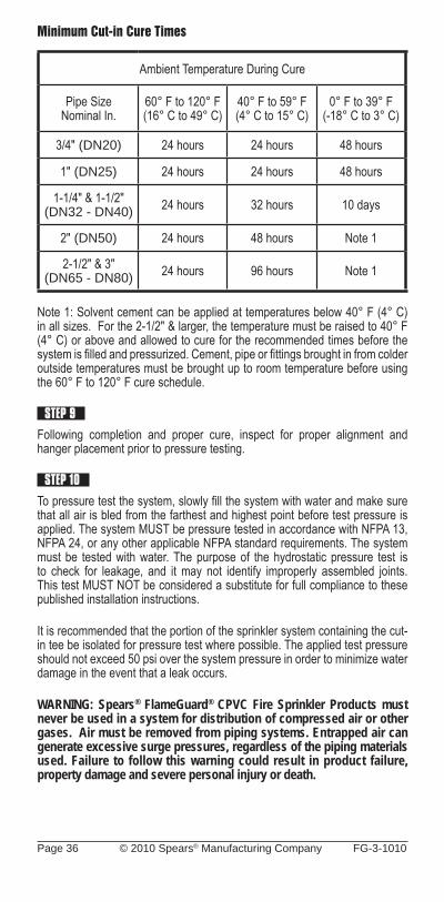
Page 36 © 2010 Spears® Manufacturing Company FG-3-1010
Minimum Cut-in Cure Times
Ambient Temperature During Cure
Pipe SizeNominal In.
60° F to 120° F(16° C to 49° C)
40° F to 59° F(4° C to 15° C)
0° F to 39° F(-18° C to 3° C)
3/4" (DN20) 24 hours 24 hours 48 hours
1" (DN25) 24 hours 24 hours 48 hours
1-1/4" & 1-1/2"(DN32 - DN40) 24 hours 32 hours 10 days
2" (DN50) 24 hours 48 hours Note 1
2-1/2" & 3"(DN65 - DN80) 24 hours 96 hours Note 1
Note 1: Solvent cement can be applied at temperatures below 40° F (4° C) in all sizes. For the 2-1/2" & larger, the temperature must be raised to 40° F (4° C) or above and allowed to cure for the recommended times before the system is fi lled and pressurized. Cement, pipe or fi ttings brought in from colder outside temperatures must be brought up to room temperature before using the 60° F to 120° F cure schedule.
STEP 9
Following completion and proper cure, inspect for proper alignment and hanger placement prior to pressure testing.
STEP 10
To pressure test the system, slowly fi ll the system with water and make sure that all air is bled from the farthest and highest point before test pressure is applied. The system MUST be pressure tested in accordance with NFPA 13, NFPA 24, or any other applicable NFPA standard requirements. The system must be tested with water. The purpose of the hydrostatic pressure test is to check for leakage, and it may not identify improperly assembled joints. This test MUST NOT be considered a substitute for full compliance to these published installation instructions.
It is recommended that the portion of the sprinkler system containing the cut-in tee be isolated for pressure test where possible. The applied test pressure should not exceed 50 psi over the system pressure in order to minimize water damage in the event that a leak occurs.
WARNING: Spears® FlameGuard® CPVC Fire Sprinkler Products must never be used in a system for distribution of compressed air or other gases. Air must be removed from piping systems. Entrapped air can generate excessive surge pressures, regardless of the piping materials used. Failure to follow this warning could result in product failure, property damage and severe personal injury or death.
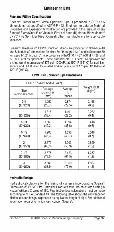
FG-3-1010 © 2010 Spears® Manufacturing Company Page 37
Engineering Data
Pipe and Fitting Specifi cationsSpears® FlameGuard® CPVC Sprinkler Pipe is produced in SDR 13.5 dimensions, as specified in ASTM F 442. Engineering data on Material Properties and Expansion & Contraction are provided in this manual for (A) Spears® FlameGuard® or Victaulic FireLock® and (B) Harvel BlazeMaster® CPVC Fire Sprinkler Pipe. Consult other manufacturers for applicable variations
Spears® FlameGuard® CPVC Sprinkler Fittings are produced in Schedule 40 and Schedule 80 dimensions for sizes 3/4" through 1-1/4", and in Schedule 80 for sizes 1-1/2" through 3", in accordance with ASTM F 437, ASTM F 438, and ASTM F 439 as applicable. These products are UL Listed FM/Approved for a rated working pressure of 175 psi (1200kPa)at 150° F (65° C) for sprinkler service and LPCB listed for a rated working pressure of 175 psi (1200kPa) at 120° F (49° C).
CPVC Fire Sprinkler Pipe Dimensions
SDR 13.5 (Ref. ASTM F442)Weight lbs/ft
(kg/m)SizeNominal inches
AverageOD inches
(mm)
AverageID
inches3/4
(DN20)1.050(26,7)
0.874(22,5)
0.168(0,2)
1 (DN25)
1.315(33,4)
1.101(28,2)
0.262(0,4)
1-1/4 (DN32)
1.660(42,2)
1.394(35,6)
0.418(0,6)
1-1/2 (DN40)
1.900(48,3)
1.598(40,7)
0.548(0,7)
2 (DN50)
2.375(60,3)
2.003(50,9)
0.859(1,2)
2-1/2 (DN65)
2.875(73,0)
2.423(61,5)
1.257(1,2)
3 (DN80)
3.500(88,9)
2.950(75,0)
1.867(1,2)
Hydraulic DesignHydraulic calculations for the sizing of systems incorporating Spears® FlameGuard® CPVC Fire Sprinkler Products must be calculated using a Hazen-Williams C value of 150. Pipe friction loss calculations must be made according to NFPA Standard 13. The following table shows the allowance for friction loss for fi ttings, expressed as equivalent length of pipe. For additional information regarding friction loss, contact Spears®.
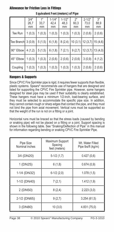
Page 38 © 2010 Spears® Manufacturing Company FG-3-1010
Allowance for Friction Loss in FittingsEquivalent Feet (meters) of Pipe
3/4"26,7mm
1"33,7mm
1-1/4"42,4mm
1-1/2"48,3mm
2"60,3mm
2-1/2"73,0mm
3"88,9mm
Tee Run 1 (0,3) 1 (0,3) 1 (0,3) 1 (0,3) 1 (0,3) 2 (0,6) 2 (0,6)
Tee Branch 3 (0,9) 5 (1,5) 6 (1,8) 8 (2,4) 10 (3,1) 12 (3,7) 15 (4,6)
90° Elbow 4 (1,2) 5 (1,5) 6 (1,8) 7 (2,1) 9 (2,7) 12 (3,7) 13 (4,0)
45° Elbow 1 (0,3) 1 (0,3) 2 (0,6) 2 (0,6) 2 (0,6) 3 (0,9) 4 (1,2)
Coupling 1 (0,3) 1 (0,3) 1 (0,3) 1 (0,3) 1 (0,3) 2 (0,6) 2 (0,6)
Hangers & SupportsSince CPVC Fire Sprinkler pipe is rigid, it requires fewer supports than fl exible, plastic systems. Spears® recommends use of hangers that are designed and listed for supporting the CPVC Fire Sprinkler pipe. However, some hangers designed for steel pipe may be used if their suitability is clearly established. These hangers must have a minimum 1/2-inch, load-bearing surface, and they must be selected to accommodate the specifi c pipe size. In addition, they cannot contain rough or sharp edges that contact the pipe, and they must not bind the pipe from axial movement. Vertical runs must be supported so that the weight of the run is not on a fi tting or a joint.
Horizontal runs must be braced so that the stress loads (caused by bending or snaking pipe) will not be placed on a fi tting or a joint. Support spacing is shown in the following table. See “Snaking/Defl ection of Pipe” in this manual for information regarding bending or snaking CPVC Fire Sprinkler Pipe.
Pipe SizeNominal inches
Maximum SupportSpacing
feet (meters)Wt. Water FilledPipe lbs/ft (kg/m)
3/4 (DN20) 5-1/2 (1,7) 0.427 (0,6)
1 (DN25) 6 (1,8) 0.674 (0,9)
1-1/4 (DN32) 6-1/2 (2,0) 1.078 (1,5)
1-1/2 (DN40) 7 (2,1) 1.412 (1,9)
2 (DN50) 8 (2,4) 2.223 (3,0)
2-1/2 (DN65) 9 (2,7) 3.254 (61,5)
3 (DN80) 10 (3,0) 4.831 (75,0)
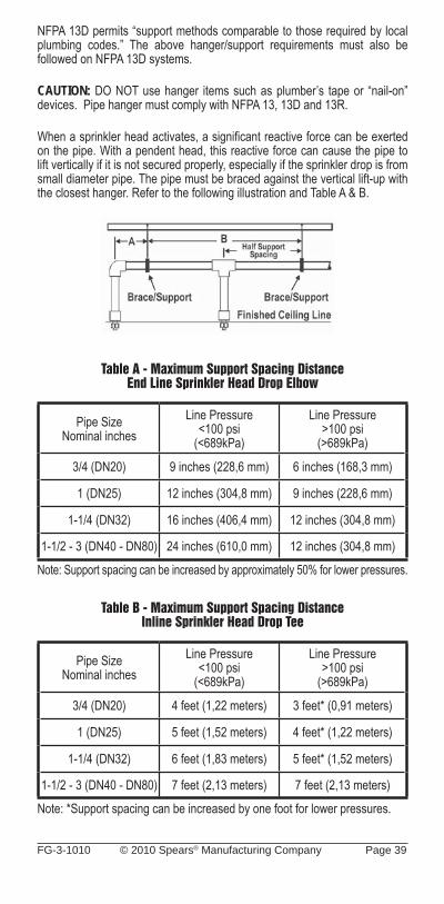
FG-3-1010 © 2010 Spears® Manufacturing Company Page 39
NFPA 13D permits “support methods comparable to those required by local plumbing codes.” The above hanger/support requirements must also be followed on NFPA 13D systems.
CAUTION: DO NOT use hanger items such as plumber’s tape or “nail-on” devices. Pipe hanger must comply with NFPA 13, 13D and 13R.
When a sprinkler head activates, a signifi cant reactive force can be exerted on the pipe. With a pendent head, this reactive force can cause the pipe to lift vertically if it is not secured properly, especially if the sprinkler drop is from small diameter pipe. The pipe must be braced against the vertical lift-up with the closest hanger. Refer to the following illustration and Table A & B.
Table A - Maximum Support Spacing DistanceEnd Line Sprinkler Head Drop Elbow
Pipe SizeNominal inches
Line Pressure<100 psi
(<689kPa)
Line Pressure>100 psi
(>689kPa)
3/4 (DN20) 9 inches (228,6 mm) 6 inches (168,3 mm)
1 (DN25) 12 inches (304,8 mm) 9 inches (228,6 mm)
1-1/4 (DN32) 16 inches (406,4 mm) 12 inches (304,8 mm)
1-1/2 - 3 (DN40 - DN80) 24 inches (610,0 mm) 12 inches (304,8 mm)
Note: Support spacing can be increased by approximately 50% for lower pressures.
Table B - Maximum Support Spacing DistanceInline Sprinkler Head Drop Tee
Pipe SizeNominal inches
Line Pressure<100 psi
(<689kPa)
Line Pressure>100 psi
(>689kPa)
3/4 (DN20) 4 feet (1,22 meters) 3 feet* (0,91 meters)
1 (DN25) 5 feet (1,52 meters) 4 feet* (1,22 meters)
1-1/4 (DN32) 6 feet (1,83 meters) 5 feet* (1,52 meters)
1-1/2 - 3 (DN40 - DN80) 7 feet (2,13 meters) 7 feet (2,13 meters)
Note: *Support spacing can be increased by one foot for lower pressures.
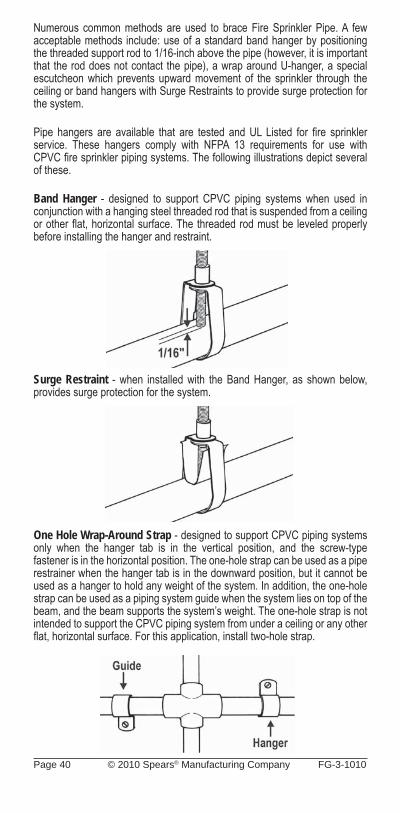
Page 40 © 2010 Spears® Manufacturing Company FG-3-1010
Numerous common methods are used to brace Fire Sprinkler Pipe. A few acceptable methods include: use of a standard band hanger by positioning the threaded support rod to 1/16-inch above the pipe (however, it is important that the rod does not contact the pipe), a wrap around U-hanger, a special escutcheon which prevents upward movement of the sprinkler through the ceiling or band hangers with Surge Restraints to provide surge protection for the system.
Pipe hangers are available that are tested and UL Listed for fi re sprinkler service. These hangers comply with NFPA 13 requirements for use with CPVC fi re sprinkler piping systems. The following illustrations depict several of these.
Band Hanger - designed to support CPVC piping systems when used in conjunction with a hanging steel threaded rod that is suspended from a ceiling or other fl at, horizontal surface. The threaded rod must be leveled properly before installing the hanger and restraint.
Surge Restraint - when installed with the Band Hanger, as shown below, provides surge protection for the system.
One Hole Wrap-Around Strap - designed to support CPVC piping systems only when the hanger tab is in the vertical position, and the screw-type fastener is in the horizontal position. The one-hole strap can be used as a pipe restrainer when the hanger tab is in the downward position, but it cannot be used as a hanger to hold any weight of the system. In addition, the one-hole strap can be used as a piping system guide when the system lies on top of the beam, and the beam supports the system’s weight. The one-hole strap is not intended to support the CPVC piping system from under a ceiling or any other fl at, horizontal surface. For this application, install two-hole strap.
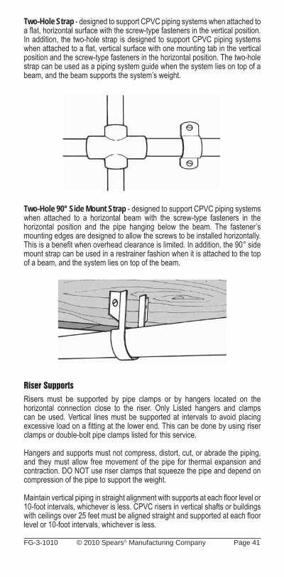
FG-3-1010 © 2010 Spears® Manufacturing Company Page 41
Two-Hole Strap - designed to support CPVC piping systems when attached to a fl at, horizontal surface with the screw-type fasteners in the vertical position. In addition, the two-hole strap is designed to support CPVC piping systems when attached to a fl at, vertical surface with one mounting tab in the vertical position and the screw-type fasteners in the horizontal position. The two-hole strap can be used as a piping system guide when the system lies on top of a beam, and the beam supports the system’s weight.
Two-Hole 90° Side Mount Strap - designed to support CPVC piping systems when attached to a horizontal beam with the screw-type fasteners in the horizontal position and the pipe hanging below the beam. The fastener’s mounting edges are designed to allow the screws to be installed horizontally. This is a benefi t when overhead clearance is limited. In addition, the 90° side mount strap can be used in a restrainer fashion when it is attached to the top of a beam, and the system lies on top of the beam.
Riser SupportsRisers must be supported by pipe clamps or by hangers located on the horizontal connection close to the riser. Only Listed hangers and clamps can be used. Vertical lines must be supported at intervals to avoid placing excessive load on a fi tting at the lower end. This can be done by using riser clamps or double-bolt pipe clamps listed for this service.
Hangers and supports must not compress, distort, cut, or abrade the piping, and they must allow free movement of the pipe for thermal expansion and contraction. DO NOT use riser clamps that squeeze the pipe and depend on compression of the pipe to support the weight.
Maintain vertical piping in straight alignment with supports at each fl oor level or 10-foot intervals, whichever is less. CPVC risers in vertical shafts or buildings with ceilings over 25 feet must be aligned straight and supported at each fl oor level or 10-foot intervals, whichever is less.
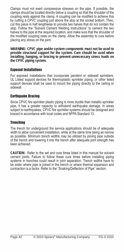
Page 42 © 2010 Spears® Manufacturing Company FG-3-1010
Clamps must not exert compressive stresses on the pipe. If possible, the clamps should be located directly below a coupling so that the shoulder of the coupling rests against the clamp. A coupling can be modifi ed to achieve this by cutting a CPVC coupling just above the stop at the socket bottom. Then, cut this piece in half lengthwise to provide two halves that do not contain the stop. Follow the “Solvent Cement Welding Instructions” to cement the two halves to the pipe at the required location, and make sure that the shoulder of the modifi ed coupling rests on the clamp. Allow the assembly to cure before placing any stress on the joint.
WARNING: CPVC pipe and/or system components must not be used to provide structural support for the system. Care should be used when installing, hanging, or bracing to prevent unnecessary stress loads on the CPVC piping system.
Exposed InstallationsFor exposed installations that incorporate pendent or sidewall sprinklers, UL Listed support devices for thermoplastic sprinkler piping, or other listed support devices shall be used to mount the piping directly to the ceiling or sidewall.
Earthquake BracingSince CPVC fi re sprinkler plastic piping is more ductile than metallic sprinkler pipe, it has a greater capacity to withstand earthquake damage. In areas subject to earthquakes, CPVC fi re sprinkler systems should be designed and braced in accordance with local codes and NFPA Standard 13.
TrenchingThe trench for underground fi re service applications should be of adequate width to allow convenient installation, while at the same time being as narrow as possible. Minimum trench widths may be utilized by joining pipe outside of the trench and lowering it into the trench after adequate joint strength has been achieved.
CAUTION - Refer to the set and cure times listed in this manual for solvent cement joints. Failure to follow these cure times before installing piping systems in trenches could result in joint separation. Trench widths have to be wider where pipe is joined in the trench or where thermal expansion and contraction is a factor. Refer to the “Snaking/Defl ection of Pipe” section.
FG-3-1010 © 2010 Spears® Manufacturing Company Page 43
Size Trench Width
Light Traffic Ground Cover
Heavy Traffic
Ground Cover
Nominal Diameter
inches/mm
Actual Outside Diameter inches/
mminches Minimum
inchesMinimum
inches
3 and under 50 and under
3.500 and under 60.3 and under 8 12 to 18 30 to 36
• Water filled pipe should be buried at least 12 inches below the maximum expected frost line.• It is recommended that thermoplastic piping be run within a metal or concrete casing when it is installed beneath surfaces that are subject to heavy weight or constant traffi c, such as roadways and railroad tracks.
The trench bottom should be continuous, relatively smooth, and free of rocks. Where ledge rock, hardpan, or boulders are encountered, it is necessary to pad the trench bottom using a minimum of four inches of tamped earth or sand beneath the pipe as a cushion and for protection of the pipe from damage.
Suffi cient cover must be maintained to keep external stress levels below acceptable design stress. Reliability and safety of service is of major importance in determining minimum cover. Local, state, and national codes may also apply.
Snaking/Defl ection of PipeNOTICE – • After CPVC pipe has been solvent cemented, snake the pipe, according to the following recommendations, beside the trench during its required drying time.• Be especially careful not to apply any stress that will disturb the undried joint.• Snaking is necessary to allow for any anticipated thermal contraction that will take place in the newly joined pipeline.
Snaking is particularly necessary on the lengths that have been solvent cemented during the late afternoon or a hot summer’s day because their drying time will extend through the cool of the night when thermal contraction of the pipe could stress the joints to the point of pull out. This snaking is especially necessary with pipe that is laid in its trench (necessitating wider trenches than recommended) and is back-fi lled with cool earth before the joints are thoroughly dry. The following information can be used in determining maximum defl ection allowable for various run lengths and pipe sizes.
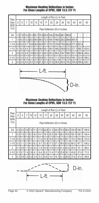
Page 44 © 2010 Spears® Manufacturing Company FG-3-1010
Maximum Bending Defl ections in InchesFor Given Lengths of CPVC, SDR 13.5 (73° F)
PipeSizeSDR13.5
Length of Run (L) in Feet
2 5 7 10 12 15 17 20 25 30 35 40 45 50
Pipe Defl ection (D) in Inches
3/4 1.3 7.8 15.4 31.3 45.1 70.5 90.6 124.4 195.9 282.1 383.9 - - -1 1.0 6.3 12.3 25.0 36.0 56.3 72.3 100.1 156.5 225.2 306.6 400.4 - -
1-1/4 0.8 5.0 9.7 19.8 28.5 44.6 57.3 79.3 123.9 178.4 242.8 317.2 401.4 -1-1/2 0.7 4.3 8.5 17.3 24.9 39.0 50.1 69.3 108.2 155.9 212.2 277.1 350.7 433.0
2 0.6 3.5 6.8 13.9 20.0 31.2 40.0 55.4 86.6 124.7 169.7 221.7 280.6 346.42-1/2 0.5 2.9 5.6 11.4 16.5 25.8 33.1 45.8 71.5 103.0 140.2 183.1 231.8 286.2
3 0.4 2.4 4.6 9.4 13.5 21.2 27.2 37.6 58.8 84.6 115.2 150.4 190.4 235.1
Maximum Snaking Defl ections in InchesFor Given Lengths of CPVC, SDR 13.5 (73° F)
PipeSizeSDR13.5
Length of Run (L) in Feet
2 5 7 10 12 15 17 20 25 30 35 40 45 50
Pipe Defl ection (D) in Inches
3/4 0.3 2.0 3.8 7.8 11.3 17.6 22.6 31.3 49.0 70.5 96.0 125.4 158.7 195.91 0.3 1.6 3.1 6.3 9.0 14.1 18.1 25.0 39.1 56.3 76.6 100.1 126.7 156.4
1-1/4 0.2 1.2 2.4 5.0 7.1 11.2 14.3 19.8 31.0 44.5 60.7 79.3 100.4 123.91-1/2 0.2 1.1 2.1 4.3 6.2 9.7 12.5 17.3 27.1 39.0 53.0 69.3 87.7 108.2
2 0.1 0.9 1.7 3.5 5.0 7.8 10.0 13.9 21.6 31.2 42.4 55.4 70.1 86.62-1/2 0.1 0.7 1.4 2.9 4.1 6.4 8.3 11.4 17.9 25.8 35.1 45.8 57.9 71.5
3 0.1 0.6 1.2 2.4 3.4 5.3 6.8 9.4 14.7 21.2 28.8 37.6 47.6 58.8
FG-3-1010 © 2010 Spears® Manufacturing Company Page 45
BACKFILLING
CAUTION - Underground pipe must be thoroughly inspected and tested for leaks prior to backfi lling (refer to section on hydrostatic pressure testing). Failure to follow this instruction could result in system failure.
During periods of hot weather, backfi lling should only be done early in the morning when the line is fully contracted, and there is no chance of insuffi ciently dried joints being subjected to contraction stresses.
The pipe should be uniformly and continuously supported over its entire length on a fi rm, stable material. Blocking should not be used to change pipe grade or to intermittently support pipe across excavated sections.
Pipe is installed in a wide range of sub-soils. These soils must be stable and applied in such a manner to physically shield the pipe from damage. Attention should be given to local pipe laying experience, which may indicate particular pipe bedding problems.
Backfi ll materials that are free of rocks with a particle size of 1/2-inch or less should be used to surround the pipe with 6 to 8 inches of cover. It should be placed in layers. Each soil layer should be sufficiently compacted to uniformly develop lateral passive soil forces during the backfill operation. It may be advisable to have the pipe under pressure, 15 to 25 psi, during the backfi lling.
Vibratory methods are preferred when compacting sand or gravels. Best results are obtained when the soils are in a nearly saturated condition. Where water-fl ooding is used, the initial backfi ll should be suffi cient to ensure complete coverage of the pipe. Additional material should not be added until the water fl ooded backfi ll is fi rm enough to walk on. Care should be taken to avoid fl oating the pipe.
Sand and gravel containing a signifi cant proportion of fi ne-grained material, such as silt and clay should be compacted by hand or, preferably, by mechanical tamper.
The remainder of the backfi ll should be spread in uniform layers to fi ll the trench completely so that there will be no unfi lled spaces around rocks or lumps of earth in the backfi ll. Large or sharp rocks, frozen clods, and other debris, greater than 3 inches in diameter, should be removed. Rolling equipment or heavy tampers should be used only to consolidate the fi nal backfi ll.
Maintenance shall be in accordance with the Standard for Inspection, Testing and Maintenance of Water Based Extinguishing Systems, as defi ned by NFPA 25.

Page 46 © 2010 Spears® Manufacturing Company FG-3-1010
Material Properties
Table I-A Modulus of Elasticity & Stress vs. Temperature
For Spears® FlameGuard® or Victaulic FireLock™ CPVC Fire Sprinkler Pipe
PropertyTemperature ° F
73 80 90 100 110 120 140 150
Modulus ofElasticity
“E” x 105 psi3.90 3.84 3.78 3.70 3.46 3.21 3.05 2.84
WorkingStress “S” psi
1,900 1,785 1,630 1,485 1,345 1,270 950 875
Table I-B Modulus of Elasticity & Stress vs. Temperature
For Harvel BlazeMaster® CPVC Fire Sprinkler Pipe
PropertyTemperature ° F
73 80 90 100 110 120 140 150
Modulus ofElasticity
“E” x 105 psi4.23 4.14 3.99 3.85 3.70 3.55 3.23 3.08
WorkingStress“S” psi
2,000 1,875 1,715 1,560 1,415 1,275 1,000 875
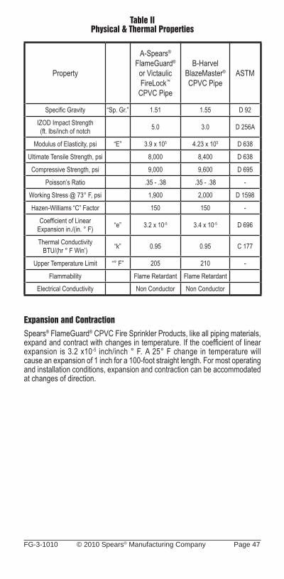
FG-3-1010 © 2010 Spears® Manufacturing Company Page 47
Table II Physical & Thermal Properties
Property
A-Spears® FlameGuard®
or Victaulic FireLock™
CPVC Pipe
B-HarvelBlazeMaster®
CPVC PipeASTM
Specifi c Gravity “Sp. Gr.” 1.51 1.55 D 92
IZOD Impact Strength(ft. lbs/inch of notch 5.0 3.0 D 256A
Modulus of Elasticity, psi “E” 3.9 x 10⁵ 4.23 x 10⁵ D 638
Ultimate Tensile Strength, psi 8,000 8,400 D 638
Compressive Strength, psi 9,000 9,600 D 695
Poisson’s Ratio .35 - .38 .35 - .38 -
Working Stress @ 73° F, psi 1,900 2,000 D 1598
Hazen-Williams “C” Factor 150 150 -
Coeffi cient of LinearExpansion in./(in. ° F) “e” 3.2 x 10⁻⁵ 3.4 x 10⁻⁵ D 696
Thermal ConductivityBTU/(hr ° F Win’) “k” 0.95 0.95 C 177
Upper Temperature Limit “° F” 205 210 -
Flammability Flame Retardant Flame Retardant
Electrical Conductivity Non Conductor Non Conductor
Expansion and ContractionSpears® FlameGuard® CPVC Fire Sprinkler Products, like all piping materials, expand and contract with changes in temperature. If the coeffi cient of linear expansion is 3.2 x10⁻⁵ inch/inch ° F. A 25° F change in temperature will cause an expansion of 1 inch for a 100-foot straight length. For most operating and installation conditions, expansion and contraction can be accommodated at changes of direction.
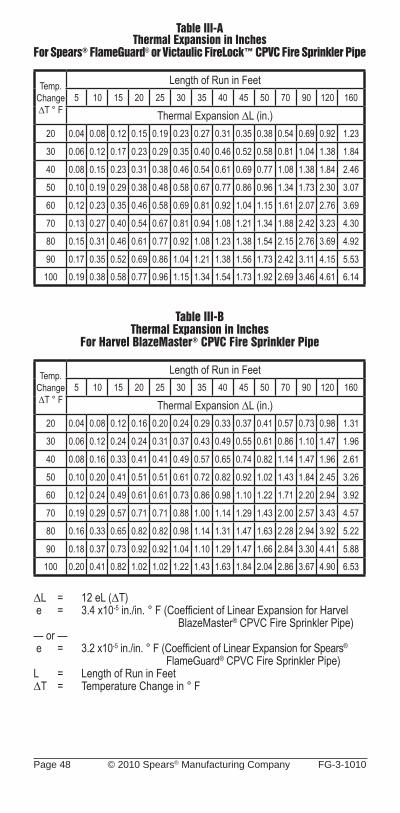
Page 48 © 2010 Spears® Manufacturing Company FG-3-1010
Table III-AThermal Expansion in Inches
For Spears® FlameGuard® or Victaulic FireLock™ CPVC Fire Sprinkler Pipe
Temp.Change∆T ° F
Length of Run in Feet5 10 15 20 25 30 35 40 45 50 70 90 120 160
Thermal Expansion ∆L (in.)20 0.04 0.08 0.12 0.15 0.19 0.23 0.27 0.31 0.35 0.38 0.54 0.69 0.92 1.23
30 0.06 0.12 0.17 0.23 0.29 0.35 0.40 0.46 0.52 0.58 0.81 1.04 1.38 1.84
40 0.08 0.15 0.23 0.31 0.38 0.46 0.54 0.61 0.69 0.77 1.08 1.38 1.84 2.46
50 0.10 0.19 0.29 0.38 0.48 0.58 0.67 0.77 0.86 0.96 1.34 1.73 2.30 3.07
60 0.12 0.23 0.35 0.46 0.58 0.69 0.81 0.92 1.04 1.15 1.61 2.07 2.76 3.69
70 0.13 0.27 0.40 0.54 0.67 0.81 0.94 1.08 1.21 1.34 1.88 2.42 3.23 4.30
80 0.15 0.31 0.46 0.61 0.77 0.92 1.08 1.23 1.38 1.54 2.15 2.76 3.69 4.92
90 0.17 0.35 0.52 0.69 0.86 1.04 1.21 1.38 1.56 1.73 2.42 3.11 4.15 5.53
100 0.19 0.38 0.58 0.77 0.96 1.15 1.34 1.54 1.73 1.92 2.69 3.46 4.61 6.14
Table III-BThermal Expansion in Inches
For Harvel BlazeMaster® CPVC Fire Sprinkler Pipe
Temp.Change∆T ° F
Length of Run in Feet5 10 15 20 25 30 35 40 45 50 70 90 120 160
Thermal Expansion ∆L (in.)20 0.04 0.08 0.12 0.16 0.20 0.24 0.29 0.33 0.37 0.41 0.57 0.73 0.98 1.31
30 0.06 0.12 0.24 0.24 0.31 0.37 0.43 0.49 0.55 0.61 0.86 1.10 1.47 1.96
40 0.08 0.16 0.33 0.41 0.41 0.49 0.57 0.65 0.74 0.82 1.14 1.47 1.96 2.61
50 0.10 0.20 0.41 0.51 0.51 0.61 0.72 0.82 0.92 1.02 1.43 1.84 2.45 3.26
60 0.12 0.24 0.49 0.61 0.61 0.73 0.86 0.98 1.10 1.22 1.71 2.20 2.94 3.92
70 0.19 0.29 0.57 0.71 0.71 0.88 1.00 1.14 1.29 1.43 2.00 2.57 3.43 4.57
80 0.16 0.33 0.65 0.82 0.82 0.98 1.14 1.31 1.47 1.63 2.28 2.94 3.92 5.22
90 0.18 0.37 0.73 0.92 0.92 1.04 1.10 1.29 1.47 1.66 2.84 3.30 4.41 5.88
100 0.20 0.41 0.82 1.02 1.02 1.22 1.43 1.63 1.84 2.04 2.86 3.67 4.90 6.53
∆L = 12 eL (∆T) e = 3.4 x10⁻⁵ in./in. ° F (Coeffi cient of Linear Expansion for Harvel BlazeMaster® CPVC Fire Sprinkler Pipe)— or — e = 3.2 x10⁻⁵ in./in. ° F (Coeffi cient of Linear Expansion for Spears®
FlameGuard® CPVC Fire Sprinkler Pipe)L = Length of Run in Feet∆T = Temperature Change in ° F
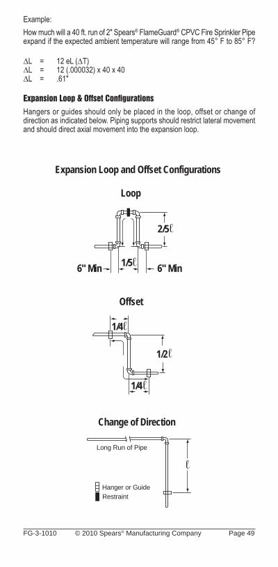
FG-3-1010 © 2010 Spears® Manufacturing Company Page 49
Example:How much will a 40 ft. run of 2" Spears® FlameGuard® CPVC Fire Sprinkler Pipe expand if the expected ambient temperature will range from 45° F to 85° F?
∆L = 12 eL (∆T)∆L = 12 (.000032) x 40 x 40∆L = .61"
Expansion Loop & Offset Confi gurationsHangers or guides should only be placed in the loop, offset or change of direction as indicated below. Piping supports should restrict lateral movement and should direct axial movement into the expansion loop.
Hanger or GuideRestraint
Long Run of Pipe
Change of Direction
Offset
Expansion Loop and Offset Configurations
Loop
6" Min 6" Min
2/5
1/5
1/4
1/2
1/4
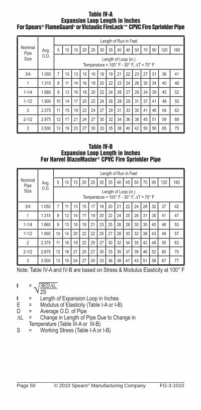
Page 50 © 2010 Spears® Manufacturing Company FG-3-1010
Table IV-AExpansion Loop Length in Inches
For Spears® FlameGuard® or Victaulic FireLock™ CPVC Fire Sprinkler Pipe
Nominal PipeSize
Avg.O.D.
Length of Run in Feet
5 10 15 20 25 30 35 40 45 50 70 90 120 160
Length of Loop (in.)Temperature = 100° F - 30° F, ∆T = 70° F
3/4 1.050 7 10 13 15 16 18 19 21 22 23 27 31 36 41
1 1.315 8 11 14 16 18 20 22 23 24 26 30 34 40 46
1-1/4 1.660 9 13 16 18 20 22 24 26 27 29 34 39 45 52
1-1/2 1.900 10 14 17 20 22 24 26 28 29 31 37 41 48 55
2 2.375 11 15 19 22 24 27 29 31 33 35 41 46 54 62
2-1/2 2.875 12 17 21 24 27 30 32 34 36 38 45 51 59 68
3 3.500 13 19 23 27 30 33 35 38 40 42 50 56 65 75
Table IV-BExpansion Loop Length in Inches
For Harvel BlazeMaster® CPVC Fire Sprinkler Pipe
Nominal PipeSize
Avg.O.D.
Length of Run in Feet
5 10 15 20 25 30 35 40 45 50 70 90 120 160
Length of Loop (in.)Temperature = 100° F - 30° F, ∆T = 70° F
3/4 1.050 7 11 13 15 17 18 20 21 22 24 28 32 37 42
1 1.315 8 12 14 17 19 20 22 24 25 26 31 35 41 47
1-1/4 1.660 9 13 16 19 21 23 25 26 28 30 35 40 46 53
1-1/2 1.900 10 14 20 22 22 25 27 28 30 32 38 43 49 57
2 2.375 11 16 19 22 25 27 30 32 34 35 42 48 55 63
2-1/2 2.875 12 18 21 25 27 30 33 35 37 39 46 52 60 70
3 3.500 13 19 24 27 30 33 36 38 41 43 51 58 67 77
Note: Table IV-A and IV-B are based on Stress & Modulus Elasticity at 100° F
l = 3ED∆L 2Sl = Length of Expansion Loop in InchesE = Modulus of Elasticity (Table I-A or I-B)D = Average O.D. of Pipe∆L = Change in Length of Pipe Due to Change in
Temperature (Table III-A or III-B)S = Working Stress (Table I-A or I-B)
√
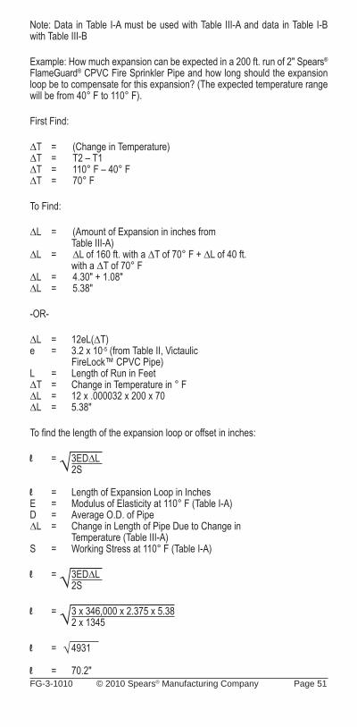
FG-3-1010 © 2010 Spears® Manufacturing Company Page 51
Note: Data in Table I-A must be used with Table III-A and data in Table I-B with Table III-B
Example: How much expansion can be expected in a 200 ft. run of 2" Spears® FlameGuard® CPVC Fire Sprinkler Pipe and how long should the expansion loop be to compensate for this expansion? (The expected temperature range will be from 40° F to 110° F).
First Find:
∆T = (Change in Temperature)∆T = T2 – T1∆T = 110° F – 40° F∆T = 70° F
To Find:
∆L = (Amount of Expansion in inches from Table III-A)∆L = ∆L of 160 ft. with a ∆T of 70° F + ∆L of 40 ft.
with a ∆T of 70° F∆L = 4.30" + 1.08"∆L = 5.38"
-OR-
∆L = 12eL(∆T)e = 3.2 x 10⁻⁵ (from Table II, Victaulic FireLock™ CPVC Pipe)L = Length of Run in Feet∆T = Change in Temperature in ° F∆L = 12 x .000032 x 200 x 70∆L = 5.38"
To fi nd the length of the expansion loop or offset in inches:
l = 3ED∆L 2S l = Length of Expansion Loop in InchesE = Modulus of Elasticity at 110° F (Table I-A)D = Average O.D. of Pipe∆L = Change in Length of Pipe Due to Change in
Temperature (Table III-A)S = Working Stress at 110° F (Table I-A)
l = 3ED∆L 2S
l = 3 x 346,000 x 2.375 x 5.38 2 x 1345
l = 4931
l = 70.2"
√
√
√√
Page 52 © 2010 Spears® Manufacturing Company FG-3-1010
Review – Do’s & Don’ts
Do’s• Read the manufacturer’s installation instructions.• Follow recommended safe work practices.• Make certain that thread sealants, gasket
lubricants, or fi re stop materials are compatible with CPVC.• Keep pipe and fi ttings in original packaging until
needed.• Cover pipe and fi ttings with an opaque tarp if
stored outdoors.• Follow proper handling procedures.• Use tools specifi cally designed for use with plastic pipe
and fi ttings.• Use the proper solvent cement and follow
application instructions.• Use a drop cloth to protect interior fi nishes.• Cut the pipe ends square.• Deburr and bevel the pipe end with a chamfering tool.• Rotate the pipe 1/4 turn when bottoming pipe in fi tting socket.• Avoid puddling of cement in fi ttings and pipe.• Make certain no solvent cement is on sprinkler head and adapter threads.• Make certain that solvent cement does not run and plug the sprinkler
head orifi ce.• Follow the manufacturer’s recommended cure times prior to pressure
testing.• Flush the entire system including drops to remove pipe shavings, dirt
and debris left from installation.• Fill lines slowly and bleed the air from the system prior to fl ushing and
pressure testing.• Support sprinkler head properly to prevent lift up of the head through the
ceiling when activated.• Keep threaded rod within 1/16" of the pipe or use a surge arrestor.• Install Spears® FlameGuard® CPVC Fire Sprinkler Products in wet
systems only.• Use only glycerin and water solutions for freeze protection.• Allow for movement due to expansion and contraction.• Renew your Spears® FlameGuard® CPVC Fire Sprinkler Products
installation training every two years.
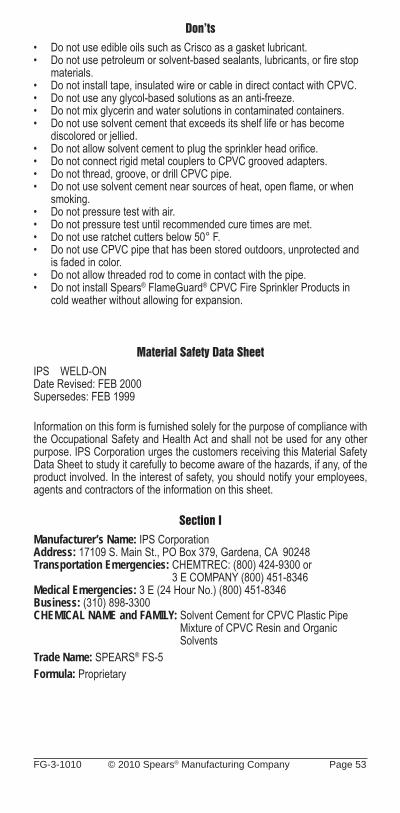
FG-3-1010 © 2010 Spears® Manufacturing Company Page 53
Don’ts• Do not use edible oils such as Crisco as a gasket lubricant.• Do not use petroleum or solvent-based sealants, lubricants, or fi re stop
materials.• Do not install tape, insulated wire or cable in direct contact with CPVC.• Do not use any glycol-based solutions as an anti-freeze.• Do not mix glycerin and water solutions in contaminated containers.• Do not use solvent cement that exceeds its shelf life or has become
discolored or jellied.• Do not allow solvent cement to plug the sprinkler head orifi ce.• Do not connect rigid metal couplers to CPVC grooved adapters.• Do not thread, groove, or drill CPVC pipe.• Do not use solvent cement near sources of heat, open fl ame, or when
smoking.• Do not pressure test with air.• Do not pressure test until recommended cure times are met.• Do not use ratchet cutters below 50° F.• Do not use CPVC pipe that has been stored outdoors, unprotected and
is faded in color.• Do not allow threaded rod to come in contact with the pipe.• Do not install Spears® FlameGuard® CPVC Fire Sprinkler Products in
cold weather without allowing for expansion.
Material Safety Data SheetIPS WELD-ONDate Revised: FEB 2000Supersedes: FEB 1999
Information on this form is furnished solely for the purpose of compliance with the Occupational Safety and Health Act and shall not be used for any other purpose. IPS Corporation urges the customers receiving this Material Safety Data Sheet to study it carefully to become aware of the hazards, if any, of the product involved. In the interest of safety, you should notify your employees, agents and contractors of the information on this sheet.
Section IManufacturer’s Name: IPS CorporationAddress: 17109 S. Main St., PO Box 379, Gardena, CA 90248Transportation Emergencies: CHEMTREC: (800) 424-9300 or 3 E COMPANY (800) 451-8346Medical Emergencies: 3 E (24 Hour No.) (800) 451-8346Business: (310) 898-3300CHEMICAL NAME and FAMILY: Solvent Cement for CPVC Plastic Pipe
Mixture of CPVC Resin and OrganicSolvents
Trade Name: SPEARS® FS-5Formula: Proprietary

Page 54 © 2010 Spears® Manufacturing Company FG-3-1010
Section II - Hazardous IngredientsNone of the ingredients below are listed as carcinogens by IARC, NTP or OSHA
Ingredient: Chlorinated Polyvinyl Chloride Resin (CPVC) Cas#: NON/HAZ ACGIH-TLV: N/A OSHA-PEL: N/A Ingredient: Tetrahydrofuran (THF)** Cas#: 109-99-9 ACGIH-TLV: 200 PPM ACGIH-STEL: 250 PPM OSHA-PEL: 200 PPM OSHA-STEL: 250 PPM DUPONT (A) AEL: 25 PPM DUPONT (B) STEL: 75 PPM Ingredient: Methyl Ethyl Ketone (MEK) Cas#: 78-93-3 Approx%: 2* ACGIH-TLV: 200 PPM ACGIH-STEL: 300 PPM OSHA-PEL: 200 PPM OSHA-STEL: 300 PPM Ingredient: Cyclohexanone Cas#: 108-94-1 ACGIH-TLV: 25 PPM Skin OSHA-PEL: 25 PPM Skin Ingredient: Acetone Cas#: 67-64-1 ACGIH-TLV: 750 PPM ACGIH-STEL: 1000 PPM OSHA-PEL: 750 PPM OSHA-STEL: 1000 PPM
*Title III Section 313 Supplier Notifi cation: This product contains toxic chemicals subject to the reporting requirements of Section 313 of the Emergency Planning and Community Right-to-Know Act of 1986 and of 40CFR372. This information must be included in all MSDS’s that are copied and distributed for this material.
(A) Dupont’s Acceptable Exposure Limit (AEL) guidelines for 8 hour and 12 hour TWA, (B) Dupont’s recommended STEL for 15 minute TWA.
** Information found in a report from the National Toxicology Program (NTP) on an inhalation study in rats and mice suggests that Tetrahydrofuran (THF) can cause tumors in animals. In the study the rats and mice were exposed to THF vapor levels up to 1800 PPM for two years (their lifetime), 6 hours/day, 5 days/week. Test results showed evidence of liver tumors in female mice and kidney tumors in male rats. No evidence of tumors was seen in female rats and male mice. There is no data linking Tetrahydrofuran exposure with cancer in humans.
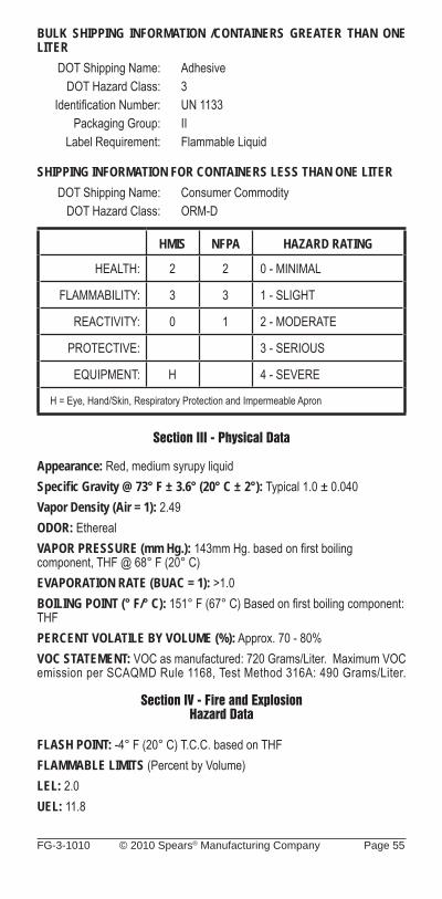
FG-3-1010 © 2010 Spears® Manufacturing Company Page 55
BULK SHIPPING INFORMATION /CONTAINERS GREATER THAN ONE LITER DOT Shipping Name: Adhesive DOT Hazard Class: 3 Identifi cation Number: UN 1133 Packaging Group: II Label Requirement: Flammable Liquid
SHIPPING INFORMATION FOR CONTAINERS LESS THAN ONE LITER DOT Shipping Name: Consumer Commodity DOT Hazard Class: ORM-D
HMIS NFPA HAZARD RATING
HEALTH: 2 2 0 - MINIMAL
FLAMMABILITY: 3 3 1 - SLIGHT
REACTIVITY: 0 1 2 - MODERATE
PROTECTIVE: 3 - SERIOUS
EQUIPMENT: H 4 - SEVERE
H = Eye, Hand/Skin, Respiratory Protection and Impermeable Apron
Section III - Physical Data
Appearance: Red, medium syrupy liquidSpecifi c Gravity @ 73° F ± 3.6° (20° C ± 2°): Typical 1.0 ± 0.040Vapor Density (Air = 1): 2.49ODOR: EtherealVAPOR PRESSURE (mm Hg.): 143mm Hg. based on fi rst boiling component, THF @ 68° F (20° C)EVAPORATION RATE (BUAC = 1): >1.0BOILING POINT (° F/° C): 151° F (67° C) Based on fi rst boiling component: THFPERCENT VOLATILE BY VOLUME (%): Approx. 70 - 80%VOC STATEMENT: VOC as manufactured: 720 Grams/Liter. Maximum VOC emission per SCAQMD Rule 1168, Test Method 316A: 490 Grams/Liter.
Section IV - Fire and ExplosionHazard Data
FLASH POINT: -4° F (20° C) T.C.C. based on THFFLAMMABLE LIMITS (Percent by Volume)LEL: 2.0UEL: 11.8
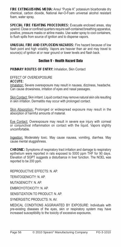
Page 56 © 2010 Spears® Manufacturing Company FG-3-1010
FIRE EXTINGUISHING MEDIA: Ansul “Purple K” potassium bicarbonate dry chemical, carbon dioxide, National Aer-O-Foam universal alcohol resistant foam, water spray.
SPECIAL FIRE FIGHTING PROCEDURES: Evacuate enclosed areas, stay upwind. Close or confi ned quarters require self-contained breathing apparatus, positive, pressure masks or airline masks. Use water spray to cool containers, to fl ush spills from source of ignition and to disperse vapors.
UNUSUAL FIRE AND EXPLOSION HAZARDS: Fire hazard because of low fl ash point and high volatility. Vapors are heavier than air and may travel to source(s) of ignition at or near ground or lower levels and fl ash back.
Section V - Health Hazard Data
PRIMARY ROUTES OF ENTRY: Inhalation, Skin Contact
EFFECT OF OVEREXPOSUREACCUTE:Inhalation: Severe overexposure may result in nausea, dizziness, headache. Can cause drowsiness, irritation of eyes and nasal passages.
Skin Contact: Skin irritant. Liquid contact may remove natural skin oils resulting in skin irritation. Dermatitis may occur with prolonged contact.
Skin Absorption: Prolonged or widespread exposure may result in the absorption of harmful amounts of material.
Eye Contact: Overexposure may result in severe eye injury with corneal or conjunctival inflammation on contact with the liquid. Vapors slightly uncomfortable.
Ingestion: Moderately toxic. May cause nausea, vomiting, diarrhea. May cause mental sluggishness.
CHRONIC: Symptoms of respiratory tract irritation and damage to respiratory epithelium were reported in rats exposed to 5000 ppm THF for 90 days. Elevation of SGPT suggests a disturbance in liver function. The NOEL was reported to be 200 ppm.
REPRODUCTIVE EFFECTS: N. AP.TERATOGENICITY: N. AP.MUTAGENICITY: N. AP.EMBROYOTOXICITY: N. AP.SENSITIZATION TO PRODUCT: N. AP.SYNERGISTIC PRODUCTS: N. AV.MEDICAL CONDITIONS AGGRAVATED BY EXPOSURE: Individuals with pre-existing diseases of the eyes, skin or respiratory system may have increased susceptibility to the toxicity of excessive exposures.
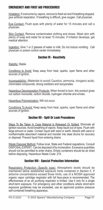
FG-3-1010 © 2010 Spears® Manufacturing Company Page 57
EMERGENCY AND FIRST AID PROCEDURES
Inhalation: If overcome by vapors, remove to fresh air and if breathing stopped, give artifi cial respiration. If breathing is diffi cult, give oxygen. Call physician.
Eye Contact: Flush eyes with plenty of water for 15 minutes and call a physician.
Skin Contact: Remove contaminated clothing and shoes. Wash skin with plenty of soap and water for at least 15 minutes. If irritation develops, get medical attention.
Ingestion: Give 1 or 2 glasses of water or milk. Do not induce vomiting. Call physician or poison control center immediately.
Section VI - Reactivity
Stability: Stable
Conditions to Avoid: Keep away from heat, sparks, open fl ame and other sources of ignition.
Incompatibility: (Materials to avoid) Caustics, ammonia, inorganic acids, chlorinated compounds, strong oxidizers and isocyanates.
Hazardous Decomposition Products: When forced to burn, this product gives out carbon monoxide, carbon dioxide, hydrogen chloride and smoke.
Hazardous Polymerization: Will not occur.
Conditions To Avoid: Keep away from heat, sparks, open flame and other sources of ignition.
Section VII - Spill Or Leak Procedures
Steps To Be Taken In Case Material Is Released Or Spilled: Eliminate all ignition sources. Avoid breathing of vapors. Keep liquid out of eyes. Flush with large amount or water. Contain liquid with sand or earth. Absorb with sand or nonfl ammable absorbent material and transfer into steel drums for recovery or disposal. Prevent liquid from entering drains.
Waste Disposal Method: Follow local, State and Federal regulations. Consult DISPOSAL EXPERT. Can be disposed of by incineration. Excessive quantities should not be permitted to enter drains. Empty containers should be air dried before disposing. Hazardous Waste Code: 214.
Section VIII - Special Protection Information
Respiratory Protection (Specify type): Atmospheric levels should be maintained below established exposure limits contained in Section II. If airborne concentrations exceed those limits, use of a NIOSH approved organic vapor cartridge respirator with full face-piece is recommended. The effectiveness of an air purifying respirator is limited. Use it only for a single short-term exposure. For emergency and other conditions where short-term exposure guidelines may be exceeded, use an approved positive pressure self-contained breathing apparatus.
Page 58 © 2010 Spears® Manufacturing Company FG-3-1010
Ventilation - Use only with adequate ventilation. Provide suffi cient ventilation in volume and pattern to keep contaminants below applicable exposure limits set forth in Section II. Use only explosion proof ventilation equipment.
Protective Gloves: PVA coated
Eye Protection: Splash proof chemical goggles
Other Protective Equipment And Hygienic Practices: Impervious apron and a source of running water to fl ush or wash the eyes and skin in case of contact.
Section IX - Special Precautions
Precautions To Be Taken In Handling And Storing: Store in the shade between 40° F - 90° F (4° C - 32.5° C). Keep away from heat, sparks, open fl ame and other sources of ignition. Avoid prolonged breathing of vapor. Use with adequate ventilation. Avoid contact with eyes, skin and clothing. Train employees on all special handling procedures before they work with this product.
Other Precautions: Follow all precautionary information given on container label, product bulletins and our solvent cementing literature. All material handling equipment should be electrically grounded.
The information contained herein is based on data considered accurate. However, no warranty is expressed or implied regarding the accuracy of this data or the results to be obtained from the use thereof.

FG-3-1010 © 2010 Spears® Manufacturing Company Page 59
NOTES__________________________________________________
__________________________________________________
__________________________________________________
__________________________________________________
__________________________________________________
__________________________________________________
__________________________________________________
__________________________________________________
__________________________________________________
__________________________________________________
__________________________________________________
__________________________________________________
__________________________________________________
__________________________________________________
__________________________________________________
__________________________________________________
__________________________________________________
__________________________________________________
__________________________________________________
__________________________________________________
__________________________________________________
__________________________________________________
__________________________________________________
__________________________________________________
__________________________________________________
__________________________________________________
__________________________________________________
__________________________________________________
__________________________________________________
__________________________________________________
__________________________________________________

Page 60 © 2010 Spears® Manufacturing Company FG-3-1010
NOTES__________________________________________________
__________________________________________________
__________________________________________________
__________________________________________________
__________________________________________________
__________________________________________________
__________________________________________________
__________________________________________________
__________________________________________________
__________________________________________________
__________________________________________________
__________________________________________________
__________________________________________________
__________________________________________________
__________________________________________________
__________________________________________________
__________________________________________________
__________________________________________________
__________________________________________________
__________________________________________________
__________________________________________________
__________________________________________________
__________________________________________________
__________________________________________________
__________________________________________________
__________________________________________________
__________________________________________________
__________________________________________________
__________________________________________________
__________________________________________________
__________________________________________________

FG-3-1010 © 2010 Spears® Manufacturing Company Page 61
NOTES__________________________________________________
__________________________________________________
__________________________________________________
__________________________________________________
__________________________________________________
__________________________________________________
__________________________________________________
__________________________________________________
__________________________________________________
__________________________________________________
__________________________________________________
__________________________________________________
__________________________________________________
__________________________________________________
__________________________________________________
__________________________________________________
__________________________________________________
__________________________________________________
__________________________________________________
__________________________________________________
__________________________________________________
__________________________________________________
__________________________________________________
__________________________________________________
__________________________________________________
__________________________________________________
__________________________________________________
__________________________________________________
__________________________________________________
__________________________________________________
__________________________________________________

Page 62 © 2010 Spears® Manufacturing Company FG-3-1010
NOTES__________________________________________________
__________________________________________________
__________________________________________________
__________________________________________________
__________________________________________________
__________________________________________________
__________________________________________________
__________________________________________________
__________________________________________________
__________________________________________________
__________________________________________________
__________________________________________________
__________________________________________________
__________________________________________________
__________________________________________________
__________________________________________________
__________________________________________________
__________________________________________________
__________________________________________________
__________________________________________________
__________________________________________________
__________________________________________________
__________________________________________________
__________________________________________________
__________________________________________________
__________________________________________________
__________________________________________________
__________________________________________________
__________________________________________________
__________________________________________________
__________________________________________________
FG-3-1010 © 2010 Spears® Manufacturing Company Page 63
SPEARS® MANUFACTURING COMPANY CORPORATE OFFICE
15853 Olden St., Sylmar, CA 91342 PO Box 9203, Sylmar, CA 91392
(818) 364-1611 • www.spearsmfg.com
PACIFIC SOUTHWEST15860 Olden St.Sylmar (Los Angeles), CA 91342(818) 364-1611 • (800) 862-1499Fax (818) 367-3014
ROCKY MOUNTAIN4880 Florence St.Denver, CO 80238(303) 371-9430 • (800) 777-4154Fax (303) 375-9546
NORTHEAST590 Industrial Dr., Suite 100Lewisberry (Harrisburg), PA 17339-9532(717) 938-8844 • (800) 233-0275Fax (717) 938-6547
MIDWEST1 Gateway Ct., Suite ABolingbrook (Chicago), IL 60440(630) 759-7529 • (800) 662-6330Fax (630) 759-7515
NORTHWEST4103 C St. NE Suite 200Auburn (Seattle), WA 98002(253) 939-4433 • (800) 347-7327Fax (253) 939-7557
UTAH5395 West 1520 SouthSalt Lake City, UT 84104(303) 371-9430 • (800) 777-4154Fax (303) 375-9546
SOUTH CENTRAL1000 Lakeside ParkwayFlower Mound, TX 75028(469) 528-3000 • (800) 441-1437Fax (469) 528-3001
FLORIDA9563 Parksouth CourtOrlando, FL 32837(407) 843-1960 • (800) 327-6390Fax (407) 425-3563
SOUTHEAST4205 Newpoint Pl., Suite 100Lawrenceville (Atlanta), GA 30043(678) 985-1263 • (800) 662-6326Fax (678) 985-5642
INTERNATIONAL SALES15853 Olden St.Sylmar (Los Angeles), CA 91342(818) 364-1611 • Fax (818) 898-3774
Authorized Distributor
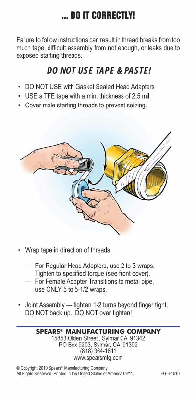
© Copyright 2010 Spears® Manufacturing Company All Rights Reserved. Printed in the United States of America 09/11. FG-3-1010
... DO IT CORRECTLY!
Failure to follow instructions can result in thread breaks from too much tape, diffi cult assembly from not enough, or leaks due to exposed starting threads.
DO NOT USE TAPE & PASTE!• DO NOT USE with Gasket Sealed Head Adapters• USE a TFE tape with a min. thickness of 2.5 mil.• Cover male starting threads to prevent seizing.
• Wrap tape in direction of threads.
— For Regular Head Adapters, use 2 to 3 wraps. Tighten to specifi ed torque (see front cover). — For Female Adapter Transitions to metal pipe, use ONLY 5 to 5-1/2 wraps.
• Joint Assembly — tighten 1-2 turns beyond fi nger tight. DO NOT back up. DO NOT over tighten!
SPEARS® MANUFACTURING COMPANY15853 Olden Street , Sylmar CA 91342
PO Box 9203, Sylmar, CA 91392(818) 364-1611
www.spearsmfg.com