Embed Size (px)
Citation preview

CRAB CAVITIES FOR THE LHC UPGRADE
Rama Calaga, CERN, Geneva, Switzerland
Abstract
The talk will review the motivation and the evolution ofthe crab cavity technology for luminosity enhancement andleveling for the HL-LHC upgrade project. The present sta-tus and the foreseen roadmap for the crab-cavity system isalso presented.
INTRODUCTION
Controlled experiments to assess the effect of the para-sitic interactions as a function of crossing angle indicatethat the present separation of approximately 10σ in thecommon regions of the interaction regions is required [1].For this experiment, a 50 ns bunch spacing with 36 bunchesand 2 head-on collisions at IP1 and IP5 with 8-16 long-range interactions per IP were used. The separation be-tween the two beams, first in IP1, and then in IP5 werereduced systematically via the crossing angle. Figure 3shows the total bunch-by-bunch losses as a function of re-duced separation only for IP1. The baseline losses are indi-cated by the 12 non-colliding bunches at the bottom. From
Figure 1: Bunch-by-bunch losses for beam 1 with con-trolled reduction of crossing angle at IR1.
this experiment, it can be concluded that the bunches withthe most number of long-range interactions suffer the high-est losses and the onset of steep losses start approximatelyat 5σ. The increase in losses can be interpreted as the re-duction in dynamic aperture as a function of the increasedlong-range effects [1].
Some relevant parameters for the LHC design and up-grade are listed in Table 1. For the nominal design andforeseen upgrade parameters, the maximum number oflong-range interactions reach a maximum of 120 or more.Therefore, a sufficiently large crossing angle leading to anapproximate separation of 10σ becomes inevitable.
Table 1: Some relevant parameters for the LHC nominaland upgrade lattices.
Unit Nominal UpgradeEnergy [TeV] 3.5-7 7p/bunch [1011] 1.15 1.7-2.0Bunch Spacing [ns] 50-25 25εn (x,y) [μm] 2.5 2.5-3.75σz (rms) [cm] 7.55 7.55IP1,5 β
∗ [cm] 55-100 15-25Betatron Tunes - {64.31, 59.32}X-Angle: 2φc [μrad] 250-315 470-580Piwinski Angle σz
σ∗φc ≤0.7 ≥2.5Main/Crab RF [MHz] 400Peak luminosity [1034 cm−2s−1] 1.0 20
CROSSING ANGLE
The consequence of the increased crossing angle is a re-duction of the potential luminosity (see Fig. 2) comparedto that of a pure head-on collision.
Figure 2: Schematic of the bunch crossing to illustrate theinefficient overlap.
The effective luminosity with a crossing angle can beconveniently represented as a Piwinski reduction factorRΦ
given by
RΦ =1√
1 + Φ2. (1)
Here, Φ = σz
σ∗xφ and φ is the half crossing angle. This
reduction can alternately be illustrated as an increase in theeffective transverse size given by
σeff =√σ2
x + σ2zφ
2 (2)
The reduction factors for present LHC and some fore-seen upgrade parameters are listed in Table 2. Note that
Proceedings of Chamonix 2012 workshop on LHC Performance
363
the crossing angles were calculated using φ = d√ε/β∗
with d = 10σ as a minimum separation for comparisonpurposes. The actual operational crossing angles maybeempirically adjusted to minimize losses.
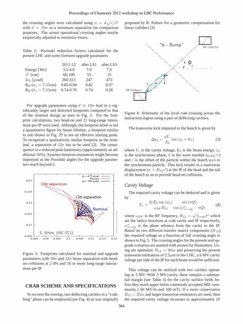
Table 2: Piwinski reduction factors calculated for thepresent LHC and some foreseen upgrade paramaters
2011-12 after LS1 after LS3Energy [Tev] 3.5-4.0 7.0 7.0β∗ [cm] 60-100 55 152φc [μrad] 260-313 247 473RΦ (σz = 7.55cm) 0.85-0.94 0.82 0.37RΦ (σz = 7.55cm) 0.74-0.76 0.74 0.28
For upgrade paramaters using d ≈ 10σ lead to a sig-nificantly larger and distorted footprints compared to thatof the nominal design as seen in Fig. 3. For the foot-print calculations, two head-on and 21 long-range intera-tions per IP were used. Although, the footprint alone is nota quantitative figure for beam lifetime, a footprint similarto one shown in Fig. ?? is not an effective starting point.To recuperate a qualitatively similar footprint as the nom-inal, a separation of 12σ has to be used [2]. The conse-quence is a reduced peak luminosity (approximately an ad-ditional 16%). Synchro-betatron resonances might becomeimportant as the Piwinski angles for the upgrade parame-ters reach beyond 2.
Figure 3: Footprints calculated for nominal and upgradeparameters with 10σ and 12σ beam separation with head-on collisions at 2 IPs and 16 or more long-range interac-tions per IP.
CRAB SCHEME AND SPECIFICATIONS
To recover the overlap, two deflecting cavities in a “crab-bing” phase can be employed (see Fig. 4) as was originally
proposed by R. Palmer for a geometric compensation forlinear colliders [3].
Figure 4: Schematic of the local crab crossing across theinteraction region using a pair of deflecting cavities.
The transverse kick imparted to the bunch is given by
Δpx =qVc
Ebsin (φs + kz) (3)
where Vc is the cavity voltage, Eb is the beam energy, φs
is the synchronous phase, k is the wave number (ωRF /c)and z is the offset of the particle within the bunch w.r.t tothe synchronous particle. This kick results in a transversedisplacement (x = R12x
′) at the IP of the head and the tailof the bunch so as to provide head-on collisions.
Cavity Voltage
The required cavity voltage can be deduced and is givenby
Vc =2cEb tan (φc)
ωRFR12
sin (πQ)
cos (ψxcc→ip − πQ)
(4)
where ωRF is the RF frequency, R12 =√βcrabβ∗ which
are the lattice functions at crab cavity and IP respectively,ψx
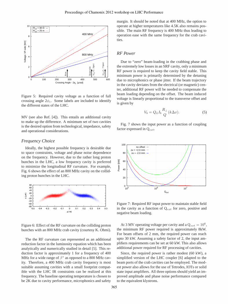
cc→ip is the phase advance from the cavity to the IP.Based on two different transfer matrix components (R12)the required voltage as a function of full crossing angle isshown in Fig. 5. The crossing angles for the present and up-grade scenarios are marked with arrows for illustration. Us-ing am optimistic R12 = 30m and preserving the presenttransverse emittances of 2.5μm in the LHC, a 6 MV cavityvoltage per side of the IP for each beam would be sufficient.
This voltage can be realized with two cavities operat-ing at 3 MV. With 3 MV/cavity, there remains a substan-tial margin (see Table 3) for the cavity surface fields be-fore they reach upper limits commonly accepted SRF com-munity ( 60 MV/m and 100 mT). If a more conservativeR12 = 25m and larger transverse emittances are used, thenthe required cavity voltage increases to approximately 10
Proceedings of Chamonix 2012 workshop on LHC Performance
364
0
2
4
6
8
10
0 100 200 300 400 500 600
Vol
tage
/ IP
-sid
e [M
V]
Crossing Angle - 2φc [μrad]
Now
Upgrade
(ε n=2.5
μm)
(ε n=3.75
μm)
400 MHz
800 MHz
R12 = 30 mR12 = 25 m
Figure 5: Required cavity voltage as a function of fullcrossing angle 2φc. Some labels are included to identifythe different states of the LHC.
MV (see also Ref. [4]). This entails an additional cavityto make up the difference. A minimum set of two cavitiesis the desired option from technological, impedance, safetyand operational considerations.
Frequency Choice
Ideally, the highest possible frequency is desirable dueto space constraints, voltage and phase noise dependenceon the frequency. However, due to the rather long protonbunches in the LHC, a low frequency cavity is preferredto minimize the longitudinal RF curvature. For example,Fig. 6 shows the effect of an 800 MHz cavity on the collid-ing proton bunches in the LHC.
Figure 6: Effect of the RF curvature on the colliding protonbunches with an 800 MHz crab cavity (courtesy K. Ohmi).
The the RF curvature can represented as an additionalreduction factor in the luminosity equation which has beenanalytically and numerically studied in detail [5]. This re-duction factor is approximately 1 for a frequency of 400MHz for a wide range of β∗ as opposed to a 800 MHz cav-ity. Therefore, a 400 MHz crab cavity frequency is mostsuitable assuming cavities with a small footprint compat-ible with the LHC IR constraints can be realized at thisfrequency. The baseline operating temperature is chosen tobe 2K due to cavity performance, microphonics and safety
margin. It should be noted that at 400 MHz, the option tooperate at higher temperatures like 4.5K also remains pos-sible. The main RF frequency is 400 MHz thus leading tooperation ease with the same frequency for the crab cavi-ties.
RF Power
Due to “zero” beam-loading in the crabbing phase andthe extremely low losses in an SRF cavity, only a minimumRF power is required to keep the cavity field stable. Thisminimum power is primarily determined by the detuningdue to microphonics or phase jitter. If the beam trajectoryin the cavity deviates from the electrical (or magnetic) cen-ter, additional RF power will be needed to compensate thebeam loading depending on the offset. The beam inducedvoltage is linearly proportional to the transverse offset andis given by
Vb = QLIbR⊥Q
(kΔx). (5)
Fig. 7 shows the input power as a function of couplingfactor expressed in Qext.
0
20
40
60
80
100
105 106 107
Pow
er [k
W]
Qext
no offsetΔx = +2.0 mmΔx = -2.0 mm
Figure 7: Required RF input power to maintain stable fieldin the cavity as a function of Qext for zero, positive andnegative beam loading.
At 3 MV operating voltage per cavity and a Qext = 106,the minimum RF power required is approximately 8kW.For beam offsets of 2 mm, the required power can reachupto 30 kW. Assuming a safety factor of 2, the input am-plifiers requirements can be set at 60 kW. This also allowsadditional power required for RF processing of cavities.
Since, the required power is rather modest (60 kW), asimplified version of the LHC coupler [6] adapted to thebeam ports of the crab cavities can be employed. The mod-est power also allows for the use of Tetrodes, IOTs or solidstate input amplifiers. All three options should yield an im-proved amplitude and phase noise performance comparedto the equivalent klystrons.
Proceedings of Chamonix 2012 workshop on LHC Performance
365
CAVITY GEOMETRY
Pillbox Cavity
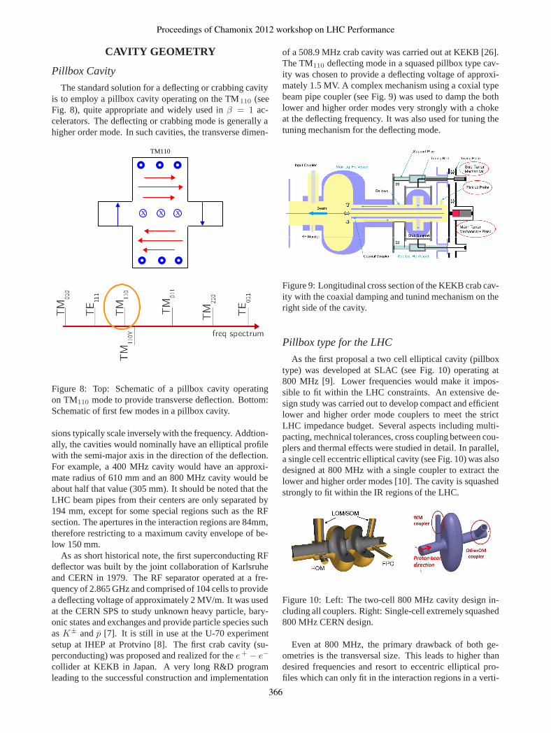
The standard solution for a deflecting or crabbing cavityis to employ a pillbox cavity operating on the TM110 (seeFig. 8), quite appropriate and widely used in β = 1 ac-celerators. The deflecting or crabbing mode is generally ahigher order mode. In such cavities, the transverse dimen-
X XX
TM110
Figure 8: Top: Schematic of a pillbox cavity operatingon TM110 mode to provide transverse deflection. Bottom:Schematic of first few modes in a pillbox cavity.
sions typically scale inversely with the frequency. Addtion-ally, the cavities would nominally have an elliptical profilewith the semi-major axis in the direction of the deflection.For example, a 400 MHz cavity would have an approxi-mate radius of 610 mm and an 800 MHz cavity would beabout half that value (305 mm). It should be noted that theLHC beam pipes from their centers are only separated by194 mm, except for some special regions such as the RFsection. The apertures in the interaction regions are 84mm,therefore restricting to a maximum cavity envelope of be-low 150 mm.
As as short historical note, the first superconducting RFdeflector was built by the joint collaboration of Karlsruheand CERN in 1979. The RF separator operated at a fre-quency of 2.865 GHz and comprised of 104 cells to providea deflecting voltage of approximately 2 MV/m. It was usedat the CERN SPS to study unknown heavy particle, bary-onic states and exchanges and provide particle species suchas K± and p̄ [7]. It is still in use at the U-70 experimentsetup at IHEP at Protvino [8]. The first crab cavity (su-perconducting) was proposed and realized for the e+ − e−
collider at KEKB in Japan. A very long R&D programleading to the successful construction and implementation
of a 508.9 MHz crab cavity was carried out at KEKB [26].The TM110 deflecting mode in a squased pillbox type cav-ity was chosen to provide a deflecting voltage of approxi-mately 1.5 MV. A complex mechanism using a coxial typebeam pipe coupler (see Fig. 9) was used to damp the bothlower and higher order modes very strongly with a chokeat the deflecting frequency. It was also used for tuning thetuning mechanism for the deflecting mode.
Figure 9: Longitudinal cross section of the KEKB crab cav-ity with the coaxial damping and tunind mechanism on theright side of the cavity.
Pillbox type for the LHC
As the first proposal a two cell elliptical cavity (pillboxtype) was developed at SLAC (see Fig. 10) operating at800 MHz [9]. Lower frequencies would make it impos-sible to fit within the LHC constraints. An extensive de-sign study was carried out to develop compact and efficientlower and higher order mode couplers to meet the strictLHC impedance budget. Several aspects including multi-pacting, mechnical tolerances, cross coupling between cou-plers and thermal effects were studied in detail. In parallel,a single cell eccentric elliptical cavity (see Fig. 10) was alsodesigned at 800 MHz with a single coupler to extract thelower and higher order modes [10]. The cavity is squashedstrongly to fit within the IR regions of the LHC.
Figure 10: Left: The two-cell 800 MHz cavity design in-cluding all couplers. Right: Single-cell extremely squashed800 MHz CERN design.
Even at 800 MHz, the primary drawback of both ge-ometries is the transversal size. This leads to higher thandesired frequencies and resort to eccentric elliptical pro-files which can only fit in the interaction regions in a verti-
Proceedings of Chamonix 2012 workshop on LHC Performance
366
cal crossing configuration. The LHC operates with a dualcrossing scheme for passive compensation of long-rangebeam-beam effects. The higher RF frequency leads to RFnon-linearity and consequent effects described in the pre-vious section. In addition, the surface field ratio to the de-flecting voltage is poor when compared to the acceleratingTM010 mode.
TEM CLASS CAVITIES
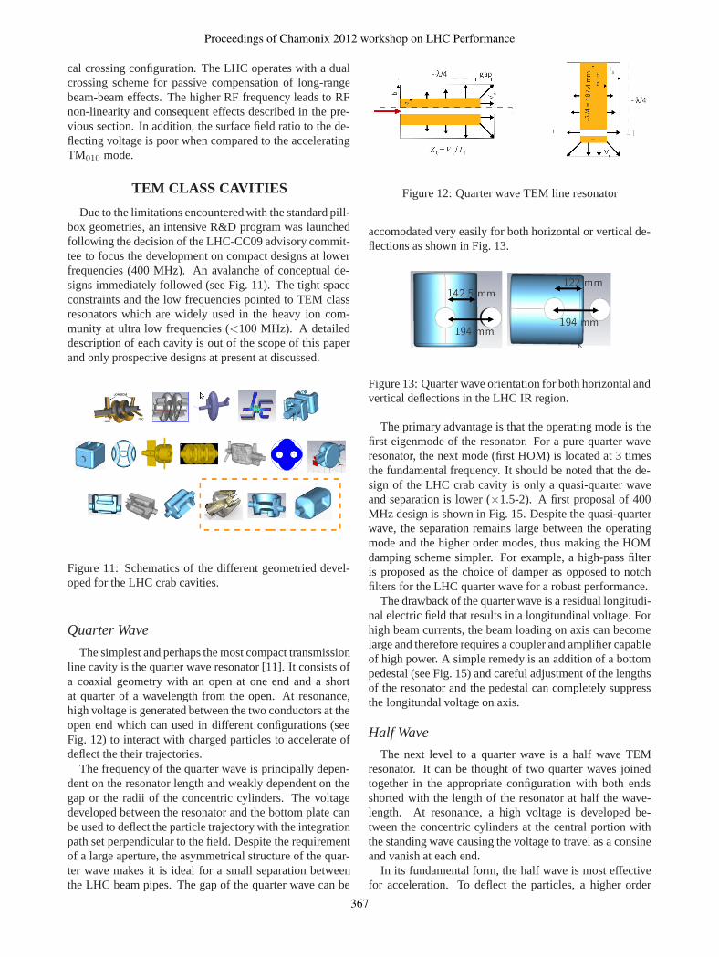
Due to the limitations encountered with the standard pill-box geometries, an intensive R&D program was launchedfollowing the decision of the LHC-CC09 advisory commit-tee to focus the development on compact designs at lowerfrequencies (400 MHz). An avalanche of conceptual de-signs immediately followed (see Fig. 11). The tight spaceconstraints and the low frequencies pointed to TEM classresonators which are widely used in the heavy ion com-munity at ultra low frequencies (<100 MHz). A detaileddescription of each cavity is out of the scope of this paperand only prospective designs at present at discussed.
Figure 11: Schematics of the different geometried devel-oped for the LHC crab cavities.
Quarter Wave
The simplest and perhaps the most compact transmissionline cavity is the quarter wave resonator [11]. It consists ofa coaxial geometry with an open at one end and a shortat quarter of a wavelength from the open. At resonance,high voltage is generated between the two conductors at theopen end which can used in different configurations (seeFig. 12) to interact with charged particles to accelerate ofdeflect the their trajectories.
The frequency of the quarter wave is principally depen-dent on the resonator length and weakly dependent on thegap or the radii of the concentric cylinders. The voltagedeveloped between the resonator and the bottom plate canbe used to deflect the particle trajectory with the integrationpath set perpendicular to the field. Despite the requirementof a large aperture, the asymmetrical structure of the quar-ter wave makes it is ideal for a small separation betweenthe LHC beam pipes. The gap of the quarter wave can be
Figure 12: Quarter wave TEM line resonator
accomodated very easily for both horizontal or vertical de-flections as shown in Fig. 13.
Figure 13: Quarter wave orientation for both horizontal andvertical deflections in the LHC IR region.
The primary advantage is that the operating mode is thefirst eigenmode of the resonator. For a pure quarter waveresonator, the next mode (first HOM) is located at 3 timesthe fundamental frequency. It should be noted that the de-sign of the LHC crab cavity is only a quasi-quarter waveand separation is lower (×1.5-2). A first proposal of 400MHz design is shown in Fig. 15. Despite the quasi-quarterwave, the separation remains large between the operatingmode and the higher order modes, thus making the HOMdamping scheme simpler. For example, a high-pass filteris proposed as the choice of damper as opposed to notchfilters for the LHC quarter wave for a robust performance.
The drawback of the quarter wave is a residual longitudi-nal electric field that results in a longitundinal voltage. Forhigh beam currents, the beam loading on axis can becomelarge and therefore requires a coupler and amplifier capableof high power. A simple remedy is an addition of a bottompedestal (see Fig. 15) and careful adjustment of the lengthsof the resonator and the pedestal can completely suppressthe longitundal voltage on axis.
Half Wave
The next level to a quarter wave is a half wave TEMresonator. It can be thought of two quarter waves joinedtogether in the appropriate configuration with both endsshorted with the length of the resonator at half the wave-length. At resonance, a high voltage is developed be-tween the concentric cylinders at the central portion withthe standing wave causing the voltage to travel as a consineand vanish at each end.
In its fundamental form, the half wave is most effectivefor acceleration. To deflect the particles, a higher order
Proceedings of Chamonix 2012 workshop on LHC Performance
367
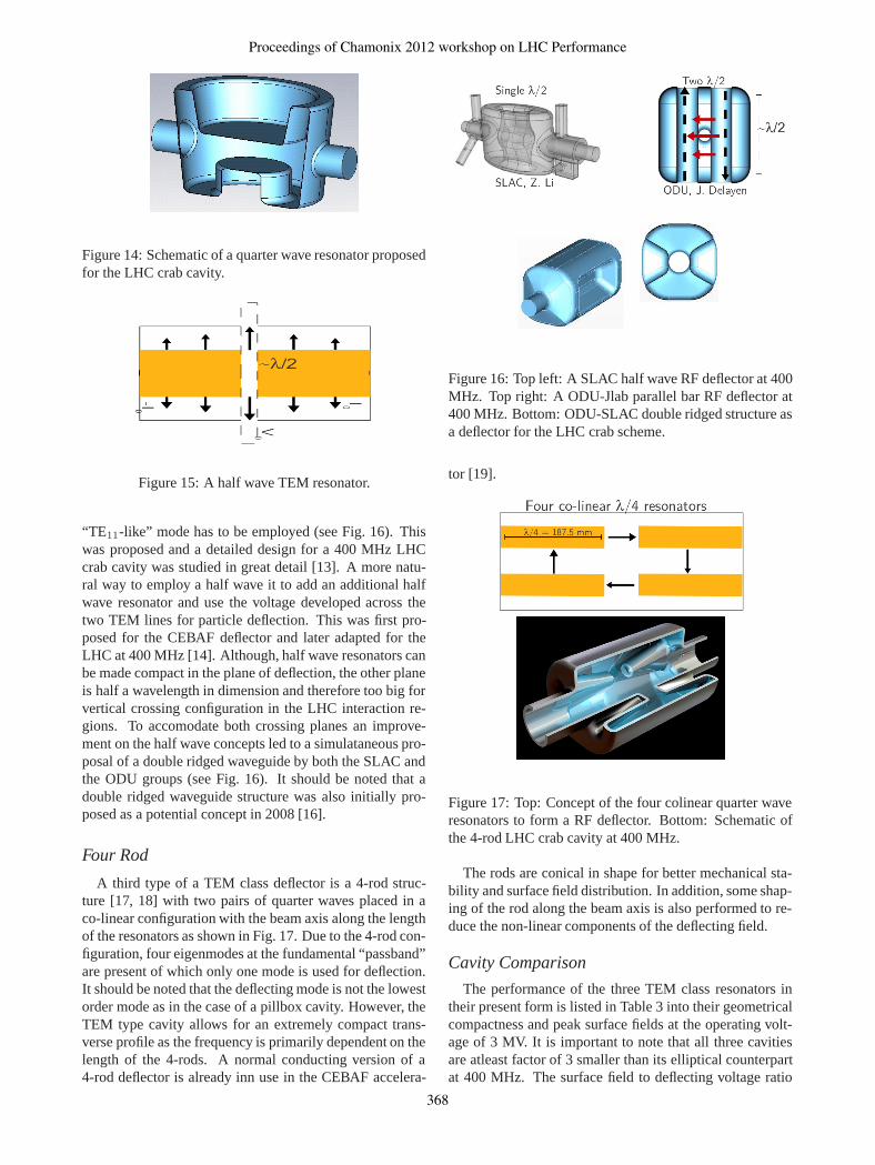
Figure 14: Schematic of a quarter wave resonator proposedfor the LHC crab cavity.
Figure 15: A half wave TEM resonator.
“TE11-like” mode has to be employed (see Fig. 16). Thiswas proposed and a detailed design for a 400 MHz LHCcrab cavity was studied in great detail [13]. A more natu-ral way to employ a half wave it to add an additional halfwave resonator and use the voltage developed across thetwo TEM lines for particle deflection. This was first pro-posed for the CEBAF deflector and later adapted for theLHC at 400 MHz [14]. Although, half wave resonators canbe made compact in the plane of deflection, the other planeis half a wavelength in dimension and therefore too big forvertical crossing configuration in the LHC interaction re-gions. To accomodate both crossing planes an improve-ment on the half wave concepts led to a simulataneous pro-posal of a double ridged waveguide by both the SLAC andthe ODU groups (see Fig. 16). It should be noted that adouble ridged waveguide structure was also initially pro-posed as a potential concept in 2008 [16].
Four Rod
A third type of a TEM class deflector is a 4-rod struc-ture [17, 18] with two pairs of quarter waves placed in aco-linear configuration with the beam axis along the lengthof the resonators as shown in Fig. 17. Due to the 4-rod con-figuration, four eigenmodes at the fundamental “passband”are present of which only one mode is used for deflection.It should be noted that the deflecting mode is not the lowestorder mode as in the case of a pillbox cavity. However, theTEM type cavity allows for an extremely compact trans-verse profile as the frequency is primarily dependent on thelength of the 4-rods. A normal conducting version of a4-rod deflector is already inn use in the CEBAF accelera-
Figure 16: Top left: A SLAC half wave RF deflector at 400MHz. Top right: A ODU-Jlab parallel bar RF deflector at400 MHz. Bottom: ODU-SLAC double ridged structure asa deflector for the LHC crab scheme.
tor [19].
Figure 17: Top: Concept of the four colinear quarter waveresonators to form a RF deflector. Bottom: Schematic ofthe 4-rod LHC crab cavity at 400 MHz.
The rods are conical in shape for better mechanical sta-bility and surface field distribution. In addition, some shap-ing of the rod along the beam axis is also performed to re-duce the non-linear components of the deflecting field.
Cavity Comparison
The performance of the three TEM class resonators intheir present form is listed in Table 3 into their geometricalcompactness and peak surface fields at the operating volt-age of 3 MV. It is important to note that all three cavitiesare atleast factor of 3 smaller than its elliptical counterpartat 400 MHz. The surface field to deflecting voltage ratio
Proceedings of Chamonix 2012 workshop on LHC Performance
368
is also better despite the significant reduction of the size.This is a direct consequence of the TEM like mode wherethe fields are more evenly distributed along the resonator.
Table 3: Geometrical and RF parameter comparsion of thethree TEM type deflectors for the LHC crab cavity at 400MHz and 3 MV.
Dbl Ridge 4-Rod 14 -Wave
ODU-SLAC LU-DL BNLCav Radius [mm] 147.5 143/118 142/122Cav length [mm] 597 500 380Aperture [mm] 84 84 84Epk [MV/m] 33 32 47Bpk [mT] 56 60.5 71R⊥/Q [Ω] 287 915 318Next HOM [MHz] 584 317-378 575
OTHER ASPECTS
Beyond the cavity geometry and deflecting kick gradi-ents, several other aspects of superconducting cavities areunder investigation to validate a complete cryomodule foroperational use in the LHC. Some pertinant topics affect-ing the cavity design including impedance, HOM damping,cavity noise, tuning and multipacting are addressed. Theissue of machine protection in the event of a fast cavityfailure is beyond the scope of this paper, but remains a criti-cal issue under investigation. Mitigation techniques such asvoltage distribution with two or more cavities, strong cavityto cavity feedback and adequate field margin are proposedand under investigation [20, 21, 22, 23].
Impedance Budget and HOM Damping
Impedance (both narrow band and broadband) from ad-ditional machine elements in the LHC like crab cavitiesneed to be minimized to ensure beam stability along theLHC energy cycle. Tolerances can be set by estimatingthe impedance requirements from Refs. [24]. In a previouscrab cavity workshop, these estimates were revised and up-dated tolerances were presented [25].
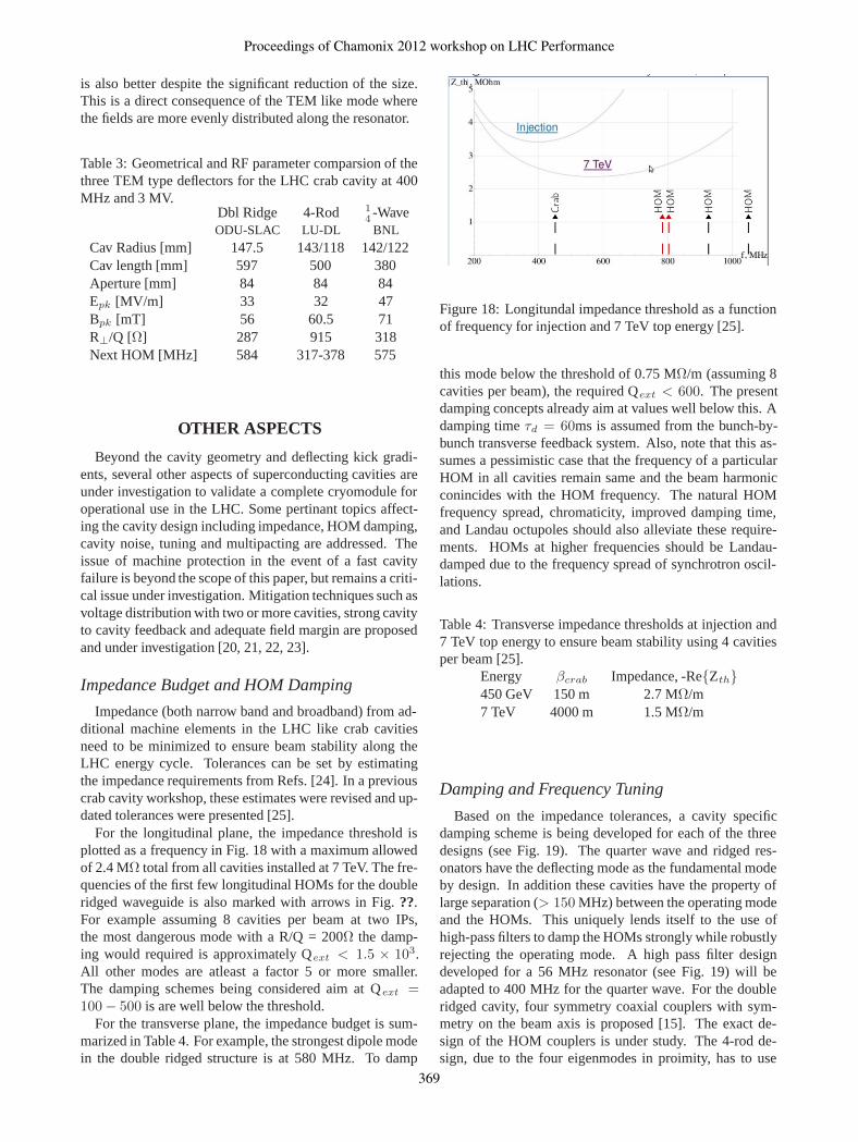
For the longitudinal plane, the impedance threshold isplotted as a frequency in Fig. 18 with a maximum allowedof 2.4 MΩ total from all cavities installed at 7 TeV. The fre-quencies of the first few longitudinal HOMs for the doubleridged waveguide is also marked with arrows in Fig. ??.For example assuming 8 cavities per beam at two IPs,the most dangerous mode with a R/Q = 200Ω the damp-ing would required is approximately Qext < 1.5 × 10³.All other modes are atleast a factor 5 or more smaller.The damping schemes being considered aim at Qext =100 − 500 is are well below the threshold.
For the transverse plane, the impedance budget is sum-marized in Table 4. For example, the strongest dipole modein the double ridged structure is at 580 MHz. To damp
Figure 18: Longitundal impedance threshold as a functionof frequency for injection and 7 TeV top energy [25].
this mode below the threshold of 0.75 MΩ/m (assuming 8cavities per beam), the required Qext < 600. The presentdamping concepts already aim at values well below this. Adamping time τd = 60ms is assumed from the bunch-by-bunch transverse feedback system. Also, note that this as-sumes a pessimistic case that the frequency of a particularHOM in all cavities remain same and the beam harmonicconincides with the HOM frequency. The natural HOMfrequency spread, chromaticity, improved damping time,and Landau octupoles should also alleviate these require-ments. HOMs at higher frequencies should be Landau-damped due to the frequency spread of synchrotron oscil-lations.
Table 4: Transverse impedance thresholds at injection and7 TeV top energy to ensure beam stability using 4 cavitiesper beam [25].
Energy βcrab Impedance, -Re{Zth}450 GeV 150 m 2.7 MΩ/m7 TeV 4000 m 1.5 MΩ/m
Damping and Frequency Tuning
Based on the impedance tolerances, a cavity specificdamping scheme is being developed for each of the threedesigns (see Fig. 19). The quarter wave and ridged res-onators have the deflecting mode as the fundamental modeby design. In addition these cavities have the property oflarge separation (> 150 MHz) between the operating modeand the HOMs. This uniquely lends itself to the use ofhigh-pass filters to damp the HOMs strongly while robustlyrejecting the operating mode. A high pass filter designdeveloped for a 56 MHz resonator (see Fig. 19) will beadapted to 400 MHz for the quarter wave. For the doubleridged cavity, four symmetry coaxial couplers with sym-metry on the beam axis is proposed [15]. The exact de-sign of the HOM couplers is under study. The 4-rod de-sign, due to the four eigenmodes in proimity, has to use
Proceedings of Chamonix 2012 workshop on LHC Performance
369
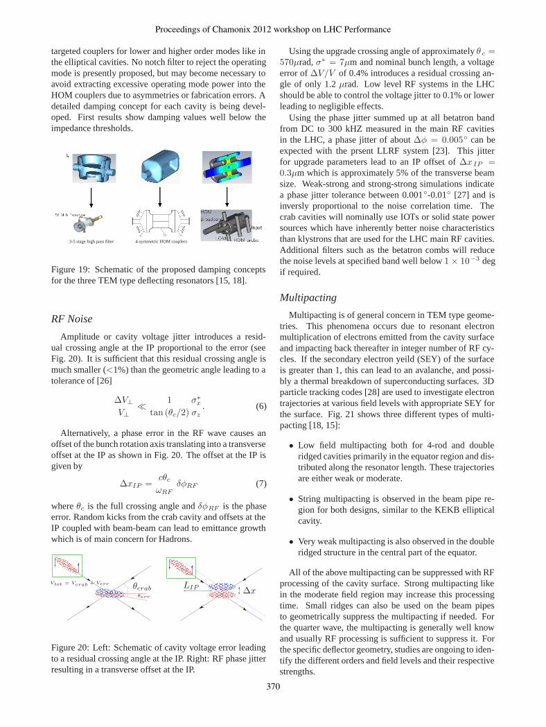
targeted couplers for lower and higher order modes like inthe elliptical cavities. No notch filter to reject the operatingmode is presently proposed, but may become necessary toavoid extracting excessive operating mode power into theHOM couplers due to asymmetries or fabrication errors. Adetailed damping concept for each cavity is being devel-oped. First results show damping values well below theimpedance thresholds.
4-symmetric HOM couplers3-5 stage high pass filter
Figure 19: Schematic of the proposed damping conceptsfor the three TEM type deflecting resonators [15, 18].
RF Noise
Amplitude or cavity voltage jitter introduces a resid-ual crossing angle at the IP proportional to the error (seeFig. 20). It is sufficient that this residual crossing angle ismuch smaller (<1%) than the geometric angle leading to atolerance of [26]
ΔV⊥V⊥
� 1
tan (θc/2)
σ∗x
σz. (6)
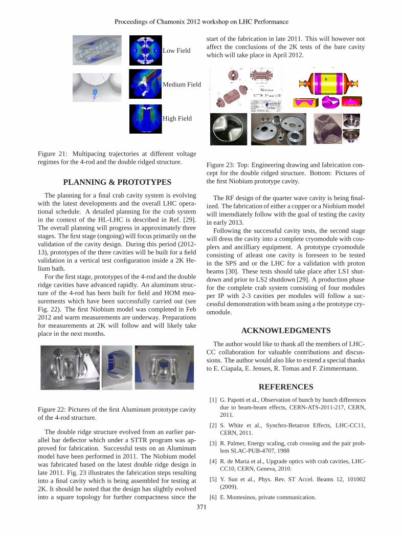
Alternatively, a phase error in the RF wave causes anoffset of the bunch rotation axis translating into a transverseoffset at the IP as shown in Fig. 20. The offset at the IP isgiven by
ΔxIP =cθc
ωRFδφRF (7)
where θc is the full crossing angle and δφRF is the phaseerror. Random kicks from the crab cavity and offsets at theIP coupled with beam-beam can lead to emittance growthwhich is of main concern for Hadrons.
������������������������������������������������������������������������������������
������������������������������������������������������������������������������������
���������������������������������������������������������������������������������������������������������������������
���������������������������������������������������������������������������������������������������������������������
������������������������������������������������������������������������������������������������������������������������������������������������������������������������������������������������������������
������������������������������������������������������������������������������������������������������������������������������������������������������������������������������������������������������������
��������������������������������������������������������������������������������������������������������������������������������������������������������������������������������
��������������������������������������������������������������������������������������������������������������������������������������������������������������������������������
������������������������������������������������������������������������������
������������������������������������������������������������������������������
�������������������������������������������������������������������������������������������
�������������������������������������������������������������������������������������������
θcrabθerr
Vtot = Vcrab + Verr
ΔxLIP
Figure 20: Left: Schematic of cavity voltage error leadingto a residual crossing angle at the IP. Right: RF phase jitterresulting in a transverse offset at the IP.
Using the upgrade crossing angle of approximately θ c =570μrad, σ∗ = 7μm and nominal bunch length, a voltageerror of ΔV/V of 0.4% introduces a residual crossing an-gle of only 1.2 μrad. Low level RF systems in the LHCshould be able to control the voltage jitter to 0.1% or lowerleading to negligible effects.
Using the phase jitter summed up at all betatron bandfrom DC to 300 kHZ measured in the main RF cavitiesin the LHC, a phase jitter of about Δφ = 0.005◦ can beexpected with the prsent LLRF system [23]. This jitterfor upgrade parameters lead to an IP offset of Δx IP =0.3μm which is approximately 5% of the transverse beamsize. Weak-strong and strong-strong simulations indicatea phase jitter tolerance between 0.001◦-0.01◦ [27] and isinversly proportional to the noise correlation time. Thecrab cavities will nominally use IOTs or solid state powersources which have inherently better noise characteristicsthan klystrons that are used for the LHC main RF cavities.Additional filters such as the betatron combs will reducethe noise levels at specified band well below 1 × 10⁻³ degif required.
Multipacting
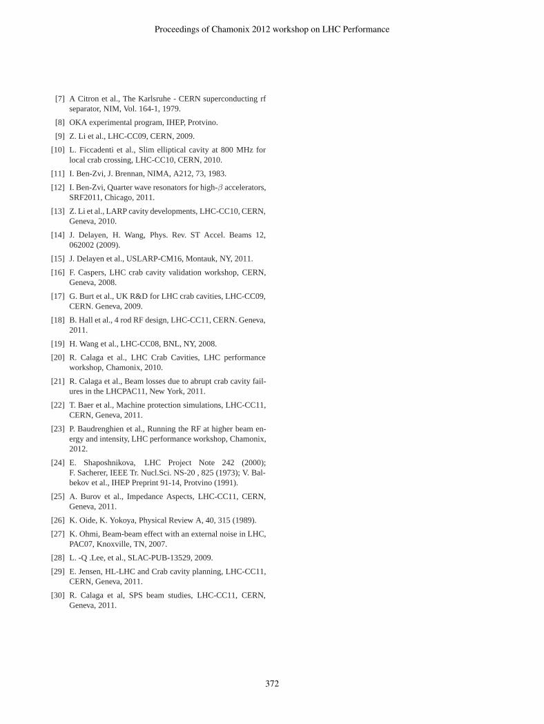
Multipacting is of general concern in TEM type geome-tries. This phenomena occurs due to resonant electronmultiplication of electrons emitted from the cavity surfaceand impacting back thereafter in integer number of RF cy-cles. If the secondary electron yeild (SEY) of the surfaceis greater than 1, this can lead to an avalanche, and possi-bly a thermal breakdown of superconducting surfaces. 3Dparticle tracking codes [28] are used to investigate electrontrajectories at various field levels with appropriate SEY forthe surface. Fig. 21 shows three different types of multi-pacting [18, 15]:
• Low field multipacting both for 4-rod and doubleridged cavities primarily in the equator region and dis-tributed along the resonator length. These trajectoriesare either weak or moderate.
• String multipacting is observed in the beam pipe re-gion for both designs, similar to the KEKB ellipticalcavity.
• Very weak multipacting is also observed in the doubleridged structure in the central part of the equator.
All of the above multipacting can be suppressed with RFprocessing of the cavity surface. Strong multipacting likein the moderate field region may increase this processingtime. Small ridges can also be used on the beam pipesto geometrically suppress the multipacting if needed. Forthe quarter wave, the multipacting is generally well knowand usually RF processing is sufficient to suppress it. Forthe specific deflector geometry, studies are ongoing to iden-tify the different orders and field levels and their respectivestrengths.
Proceedings of Chamonix 2012 workshop on LHC Performance
370
High Field
Medium Field
Low Field
Figure 21: Multipacing trajectories at different voltageregimes for the 4-rod and the double ridged structure.
PLANNING & PROTOTYPES
The planning for a final crab cavity system is evolvingwith the latest developments and the overall LHC opera-tional schedule. A detailed planning for the crab systemin the context of the HL-LHC is described in Ref. [29].The overall planning will progress in approximately threestages. The first stage (ongoing) will focus primarily on thevalidation of the cavity design. During this period (2012-13), prototypes of the three cavities will be built for a fieldvalidation in a vertical test configuration inside a 2K He-lium bath.
For the first stage, prototypes of the 4-rod and the doubleridge cavities have advanced rapidly. An aluminum struc-ture of the 4-rod has been built for field and HOM mea-surements which have been successfully carried out (seeFig. 22). The first Niobium model was completed in Feb2012 and warm measurements are underway. Preparationsfor measurements at 2K will follow and will likely takeplace in the next months.
Figure 22: Pictures of the first Aluminum prototype cavityof the 4-rod structure.
The double ridge structure evolved from an earlier par-allel bar deflector which under a STTR program was ap-proved for fabrication. Successful tests on an Aluminummodel have been performed in 2011. The Niobium modelwas fabricated based on the latest double ridge design inlate 2011. Fig. 23 illustrates the fabrication steps resultinginto a final cavity which is being assembled for testing at2K. It should be noted that the design has slightly evolvedinto a square topology for further compactness since the
start of the fabrication in late 2011. This will however notaffect the conclusions of the 2K tests of the bare cavitywhich will take place in April 2012.
Figure 23: Top: Engineering drawing and fabrication con-cept for the double ridged structure. Bottom: Pictures ofthe first Niobium prototype cavity.
The RF design of the quarter wave cavity is being final-ized. The fabrication of either a copper or a Niobium modelwill imemdiately follow with the goal of testing the cavityin early 2013.
Following the successful cavity tests, the second stagewill dress the cavity into a complete cryomodule with cou-plers and ancilliary equipment. A prototype cryomoduleconsisting of atleast one cavity is foreseen to be testedin the SPS and or the LHC for a validation with protonbeams [30]. These tests should take place after LS1 shut-down and prior to LS2 shutdown [29]. A production phasefor the complete crab system consisting of four modulesper IP with 2-3 cavities per modules will follow a suc-cessful demonstration with beam using a the prototype cry-omodule.
ACKNOWLEDGMENTS
The author would like to thank all the members of LHC-CC collaboration for valuable contributions and discus-sions. The author would also like to extend a special thanksto E. Ciapala, E. Jensen, R. Tomas and F. Zimmermann.
REFERENCES
[1] G. Papotti et al., Observation of bunch by bunch differencesdue to beam-beam effects, CERN-ATS-2011-217, CERN,2011.
[2] S. White et al., Synchro-Betatron Effects, LHC-CC11,CERN, 2011.
[3] R. Palmer, Energy scaling, crab crossing and the pair prob-lem SLAC-PUB-4707, 1988
[4] R. de Maria et al., Upgrade optics with crab cavities, LHC-CC10, CERN, Geneva, 2010.
[5] Y. Sun et al., Phys. Rev. ST Accel. Beams 12, 101002(2009).
[6] E. Montesinos, private communication.
Proceedings of Chamonix 2012 workshop on LHC Performance
371
[7] A Citron et al., The Karlsruhe - CERN superconducting rfseparator, NIM, Vol. 164-1, 1979.
[8] OKA experimental program, IHEP, Protvino.
[9] Z. Li et al., LHC-CC09, CERN, 2009.
[10] L. Ficcadenti et al., Slim elliptical cavity at 800 MHz forlocal crab crossing, LHC-CC10, CERN, 2010.
[11] I. Ben-Zvi, J. Brennan, NIMA, A212, 73, 1983.
[12] I. Ben-Zvi, Quarter wave resonators for high-β accelerators,SRF2011, Chicago, 2011.
[13] Z. Li et al., LARP cavity developments, LHC-CC10, CERN,Geneva, 2010.
[14] J. Delayen, H. Wang, Phys. Rev. ST Accel. Beams 12,062002 (2009).
[15] J. Delayen et al., USLARP-CM16, Montauk, NY, 2011.
[16] F. Caspers, LHC crab cavity validation workshop, CERN,Geneva, 2008.
[17] G. Burt et al., UK R&D for LHC crab cavities, LHC-CC09,CERN. Geneva, 2009.
[18] B. Hall et al., 4 rod RF design, LHC-CC11, CERN. Geneva,2011.
[19] H. Wang et al., LHC-CC08, BNL, NY, 2008.
[20] R. Calaga et al., LHC Crab Cavities, LHC performanceworkshop, Chamonix, 2010.
[21] R. Calaga et al., Beam losses due to abrupt crab cavity fail-ures in the LHCPAC11, New York, 2011.
[22] T. Baer et al., Machine protection simulations, LHC-CC11,CERN, Geneva, 2011.
[23] P. Baudrenghien et al., Running the RF at higher beam en-ergy and intensity, LHC performance workshop, Chamonix,2012.
[24] E. Shaposhnikova, LHC Project Note 242 (2000);F. Sacherer, IEEE Tr. Nucl.Sci. NS-20 , 825 (1973); V. Bal-bekov et al., IHEP Preprint 91-14, Protvino (1991).
[25] A. Burov et al., Impedance Aspects, LHC-CC11, CERN,Geneva, 2011.
[26] K. Oide, K. Yokoya, Physical Review A, 40, 315 (1989).
[27] K. Ohmi, Beam-beam effect with an external noise in LHC,PAC07, Knoxville, TN, 2007.
[28] L. -Q .Lee, et al., SLAC-PUB-13529, 2009.
[29] E. Jensen, HL-LHC and Crab cavity planning, LHC-CC11,CERN, Geneva, 2011.
[30] R. Calaga et al, SPS beam studies, LHC-CC11, CERN,Geneva, 2011.
Proceedings of Chamonix 2012 workshop on LHC Performance
372


![Crab Cavities: Speed of Voltage Change (a machine protection issue for LHC [and SPS] )](https://img.pdfslide.net/doc/110x75/568149ec550346895db71a65/crab-cavities-speed-of-voltage-change-a-machine-protection-issue-for-lhc.jpg)