Embed Size (px)
Citation preview
Crack and Shock Propagation through the Interlayer inSoda lime Glass under Detonation Loading
Joon Hong Choi
Department of Materials Science and Engineering, Korea Advanced Institute of Science and Technology(KAIST), 291 Daehak-ro, Yuseong-gu, Daejeon 305-701, Korea
The 5th R&D Center, Agency for Defense Development, P.O.Box 35, Yuseong-gu, Daejeon, 305-600,Korea
Do Kyung Kim*
Department of Materials Science and Engineering, Korea Advanced Institute of Science and Technology(KAIST), 291 Daehak-ro, Yuseong-gu, Daejeon 305-701, Korea
Dynamic wave interaction and crack propagation in glass have been observed with the edge-on impact (EOI) style test
method using an exploding bridged wire (EBW) detonator. The existence of an interlayer or internal surface displayed mean-ingful wave distortions, delays, reflections, and decreasing amplitude. The interlayer materials used were rubber, stainless steel,and cut surface. The results indicate that the shocks passing the interlayer decrease following the impedance condition andthat much of the crack is stopped at the interlayer. The damage pattern was analyzed with the energy and stress dissipation
rate.
Introduction
When an intense shock is loaded onto the surfaceof a material, it experiences a severe energy dump andacts to dissipate this energy through various mecha-nisms, such as physical, mechanical, or even chemicalreactions. Shock interaction is a very important field inthe research of protection mechanisms and armordesign. The huge shock energy generated by a ballisticimpact creates high stress on the material and causes
severe elastic/plastic deformation and/or increased tem-perature. The majority of modern armor does not useone type of material but a combination of variousmaterials to overcome the various types of threats.Recently, brittle nonmetallic materials such as ceramicand glass have been widely used to reduce weight andincrease ballistic performance.1,2 Many researchers havestudied the mechanism of material response when thematerial is subjected to a large shock or ballistic impactusing impact experiments and numerical analysis.3–6
Shockey et al.7 researched detailed ceramic fracturephenomena by impacting a long-rod penetrator and atungsten carbide sphere. The impact was investigated
© 2015 The American Ceramic Society and Wiley Periodicals, Inc
International Journal of Applied Glass Science, 1–14 (2015)DOI:10.1111/ijag.12133
after impact occurred by postmortem technology. Shinet al. also revealed a bulk metallic glass fracture with anexplosive detonation impact by this same postmortemtechnique.8 They performed an explosive indentationtest using a small EBW (explosive bridged wire) deto-nator. Because the majority of armor ceramics are opa-que, it is difficult to investigate their real dynamicresponses in situ by light transmission. For ceramic,such as SiC, the side faces were polished to a mirror-like finish so that cracks in the surface were observedby reflected light.9 Flash X-ray is a useful instrument inwhich the X-ray penetrates low-density brittle materialand creates an image of the material state.10,11 Thistechnology is well known. However, the resolution andthe required number of images limit the ability toacquire good information in the dynamic impact pro-cess. Because of the rise in local conflicts worldwide,the importance of transparent armor has increased. Tra-ditionally, glass laminated with a polymer film has beenthe typical material used to cope with a ballistic threat.To improve performance, transparent plastic or ceramicis considered. The key is to reduce weight and thick-ness. Good candidates for improved performance aresapphire, AlON, and some glass ceramics. Researchershave studied the characteristics of these materials in thestatic and dynamic state, as well as during ballisticimpact.12–14
Previous studies on various transparent materialsfor dynamic impact were performed using a methodcalled the “edge-on impact” (EOI) method.15 When aprojectile with a hemispheric, flat or sharply pointednose shape impacts a specimen, it generates an intenseshock, fragments the specimen and penetrates it. As theenergy delivery rate to the specimen depends on thegeometric shape of the projectile head, the propagatingwave and crack are also affected and distorted. To min-imize these effects, we considered a detonator that canload a shock pulse as a point-like source without mas-sive penetration.
In this study, we investigated the dynamic frac-ture behavior of glass in relation to the boundarycondition and shock response under intense loadingwith a small explosive detonator. The effect of theinterlayer and interface in the material on the crackgrowth and shock wave interaction was well visualizedand analyzed. This study demonstrates that acousticimpedance is an important factor for wave interactionat the interface and that it affects crack growth andpropagation.
Experimental Procedure
Material
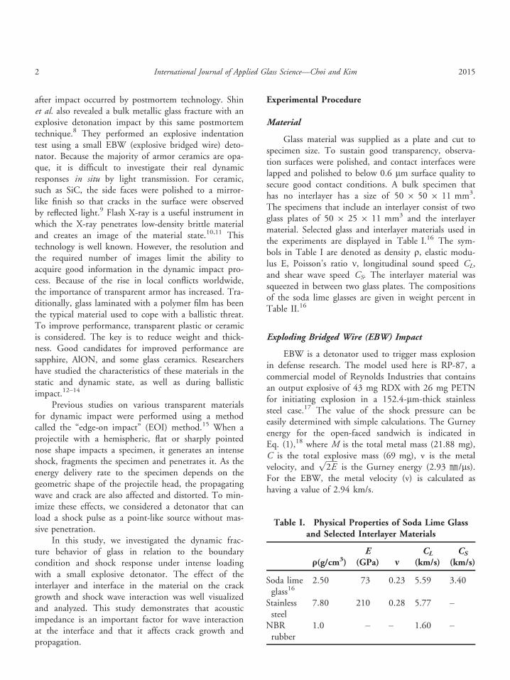
Glass material was supplied as a plate and cut tospecimen size. To sustain good transparency, observa-tion surfaces were polished, and contact interfaces werelapped and polished to below 0.6 lm surface quality tosecure good contact conditions. A bulk specimen thathas no interlayer has a size of 50 9 50 9 11 mm3.The specimens that include an interlayer consist of twoglass plates of 50 9 25 9 11 mm3 and the interlayermaterial. Selected glass and interlayer materials used inthe experiments are displayed in Table I.16 The sym-bols in Table I are denoted as density q, elastic modu-lus E, Poisson’s ratio m, longitudinal sound speed CL,and shear wave speed CS. The interlayer material wassqueezed in between two glass plates. The compositionsof the soda lime glasses are given in weight percent inTable II.16
Exploding Bridged Wire (EBW) Impact
EBW is a detonator used to trigger mass explosionin defense research. The model used here is RP-87, acommercial model of Reynolds Industries that containsan output explosive of 43 mg RDX with 26 mg PETNfor initiating explosion in a 152.4-lm-thick stainlesssteel case.17 The value of the shock pressure can beeasily determined with simple calculations. The Gurneyenergy for the open-faced sandwich is indicated inEq. (1),18 where M is the total metal mass (21.88 mg),C is the total explosive mass (69 mg), v is the metalvelocity, and
ffiffiffiffiffiffi2E
pis the Gurney energy (2.93 ㎜/ls).
For the EBW, the metal velocity (v) is calculated ashaving a value of 2.94 km/s.
Table I. Physical Properties of Soda Lime Glassand Selected Interlayer Materials
q(g/cm3)E
(GPa) mCL
(km/s)CS
(km/s)
Soda limeglass16
2.50 73 0.23 5.59 3.40
Stainlesssteel
7.80 210 0.28 5.77 –
NBRrubber
1.0 – – 1.60 –
2 International Journal of Applied Glass Science—Choi and Kim 2015
vffiffiffiffiffiffi2E
p ¼ 1þ 2MC
� �3 þ 1
6ð1þ MCÞ
þM
C
" #�12
ð1Þ
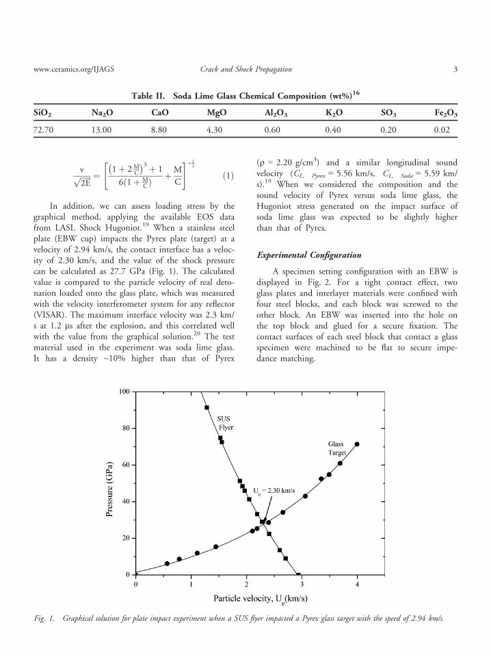
In addition, we can assess loading stress by thegraphical method, applying the available EOS datafrom LASL Shock Hugoniot.19 When a stainless steelplate (EBW cup) impacts the Pyrex plate (target) at avelocity of 2.94 km/s, the contact interface has a veloc-ity of 2.30 km/s, and the value of the shock pressurecan be calculated as 27.7 GPa (Fig. 1). The calculatedvalue is compared to the particle velocity of real deto-nation loaded onto the glass plate, which was measuredwith the velocity interferometer system for any reflector(VISAR). The maximum interface velocity was 2.3 km/s at 1.2 ls after the explosion, and this correlated wellwith the value from the graphical solution.20 The testmaterial used in the experiment was soda lime glass.It has a density ~10% higher than that of Pyrex
(q = 2.20 g/cm3) and a similar longitudinal soundvelocity (CL, Pyrex = 5.56 km/s, CL, Soda = 5.59 km/s).19 When we considered the composition and thesound velocity of Pyrex versus soda lime glass, theHugoniot stress generated on the impact surface ofsoda lime glass was expected to be slightly higherthan that of Pyrex.
Experimental Configuration
A specimen setting configuration with an EBW isdisplayed in Fig. 2. For a tight contact effect, twoglass plates and interlayer materials were confined withfour steel blocks, and each block was screwed to theother block. An EBW was inserted into the hole onthe top block and glued for a secure fixation. Thecontact surfaces of each steel block that contact a glassspecimen were machined to be flat to secure impe-dance matching.
Table II. Soda Lime Glass Chemical Composition (wt%)16
SiO2 Na2O CaO MgO Al2O3 K2O SO3 Fe2O3
72.70 13.00 8.80 4.30 0.60 0.40 0.20 0.02
Fig. 1. Graphical solution for plate impact experiment when a SUS flyer impacted a Pyrex glass target with the speed of 2.94 km/s.
www.ceramics.org/IJAGS Crack and Shock Propagation 3
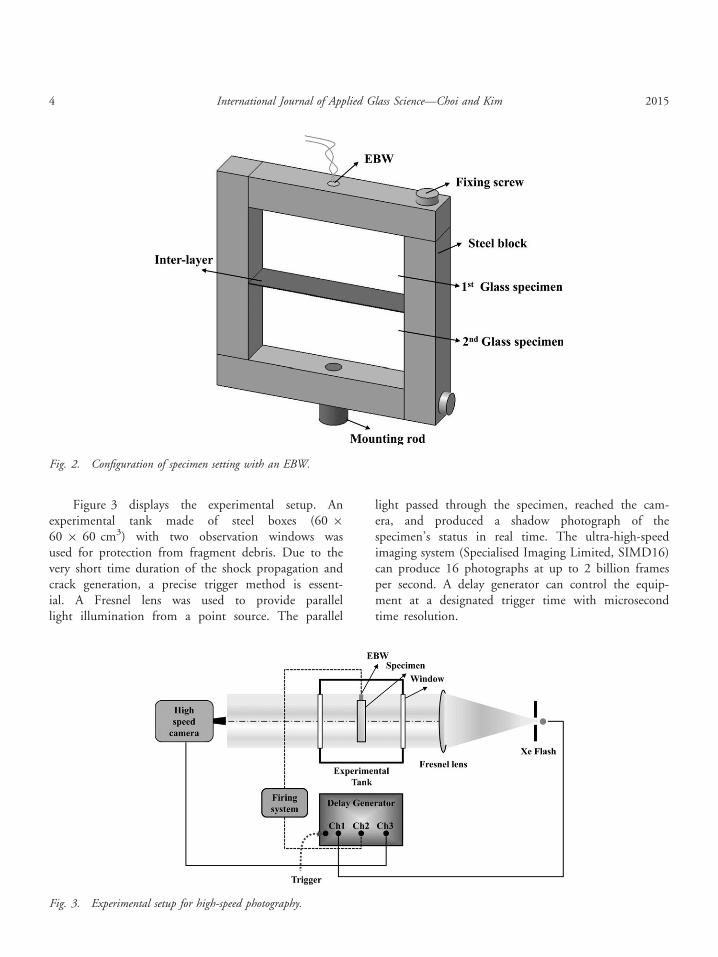
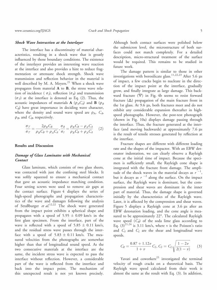
Figure 3 displays the experimental setup. Anexperimental tank made of steel boxes (60 9
60 9 60 cm3) with two observation windows wasused for protection from fragment debris. Due to thevery short time duration of the shock propagation andcrack generation, a precise trigger method is essent-ial. A Fresnel lens was used to provide parallellight illumination from a point source. The parallel
light passed through the specimen, reached the cam-era, and produced a shadow photograph of thespecimen’s status in real time. The ultra-high-speedimaging system (Specialised Imaging Limited, SIMD16)can produce 16 photographs at up to 2 billion framesper second. A delay generator can control the equip-ment at a designated trigger time with microsecondtime resolution.
Fig. 2. Configuration of specimen setting with an EBW.
Fig. 3. Experimental setup for high-speed photography.
4 International Journal of Applied Glass Science—Choi and Kim 2015
Shock Wave Interaction at the Interlayer
The interface has a discontinuity of material char-acteristics, resulting in a shock wave that is greatlyinfluenced by those boundary conditions. The existenceof the interlayer provides an interesting wave reactionat the interface and also provides a hint to reduce frag-mentation or attenuate shock strength. Shock wavetransmission and reflection behavior in the material iswell described by M. A. Meyers.21 When a shock wavepropagates from material A to B, the stress wave rela-tion of incidence ( rI), reflection (rR) and transmission(rT) at the interface is denoted as Eq. (2). Thus, theacoustic impedances of materials A (qACA) and B (qBCB) have great importance in deciding wave character,where the density and sound wave speed are qA, CA,qB, and CB, respectively.
rTrT
¼ 2qBCB
qBCB þ qACA;rRrI
¼ qBCB � qACA
qBCB þ qACAð2Þ
Results and Discussion
Damage of Glass Laminates with MechanicalContact
Glass laminate, which consists of two glass sheets,was contacted with just the confining steel blocks. Itwas softly squeezed to ensure a mechanical contactthat gave an acoustic impedance matching condition.Four setting screws were used to remove air gaps atthe contact surface. Figure 4 displays the series ofhigh-speed photographs and propagation characteris-tics of the wave and damages following the analysisof Straßburger et al.12,22 The shock wave generatedfrom the impact point exhibits a spherical shape andpropagates with a speed of 5.95 � 0.09 km/s in thefirst glass specimen. From the interface, part of thewave is reflected with a speed of 5.85 � 0.11 km/s,and the residual stress wave passes through the inter-face with a speed of 5.83 � 0.11 km/s. The mea-sured velocities from the photographs are somewhathigher than that of longitudinal sound speed. As thetwo consecutive materials at the interface are thesame, the incident stress wave is expected to pass theinterface without reflection. However, a considerablepart of the wave is reflected from the interface andback into the impact point. The mechanism ofthis unexpected result is not yet known precisely.
Although both contact surfaces were polished belowthe submicron level, the microstructure of both sur-faces could not match completely. For a detaileddescription, micro-structural treatment of the surfacewould be required. This remains to be studied infuture work.
The damage pattern is similar to those in otherinvestigations with borosilicate glass.11,22,23 After 5.6 lsof impact, a few cracks begin to nucleate in the direc-tion of the impact point at the interface, graduallygrow, and finally integrate as large damage. This back-ward fracture (▽) in Fig. 4b seems to resist forwardfracture (△) propagation of the main fracture front inthe 1st glass. At 9.6 ls, both fractures meet and do notexhibit any considerable expansion thereafter in high-speed photographs. However, the post-test photograph(shown in Fig. 10a) displays damage passing throughthe interface. Thus, the fracture generated at the inter-face (and moving backwards) at approximately 7.6 lsis the result of tensile stresses generated by reflection atthe interface.
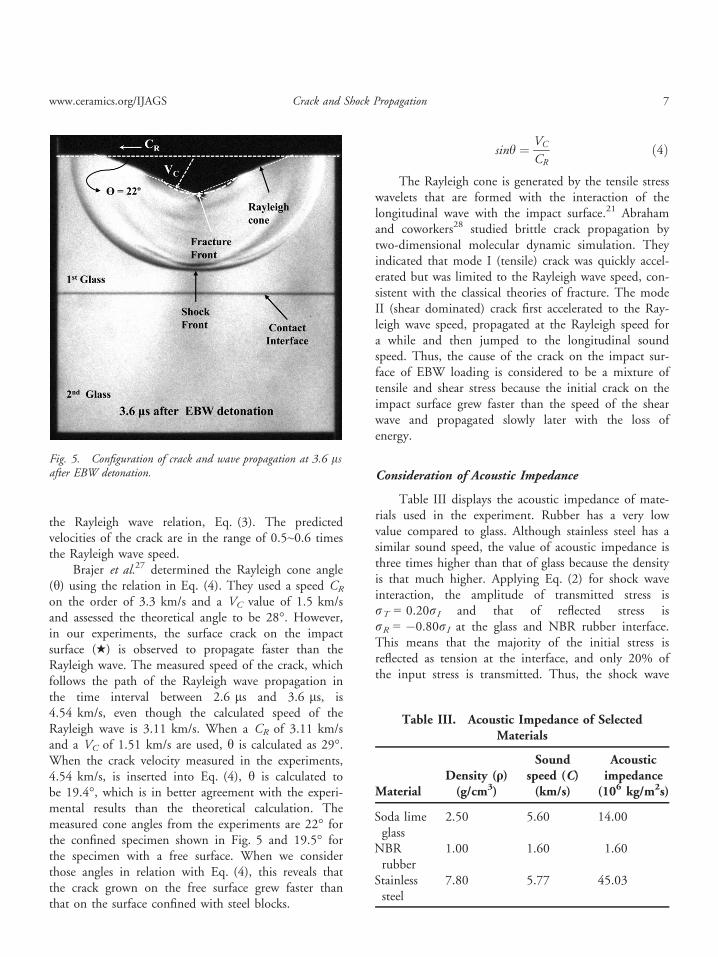
Fracture shapes are different with different loadingrate and the shapes of the impactor. With an EBW det-onator indentation, we can clearly observe a Rayleighcone at the initial time of impact. Because the speci-men is sufficiently small, the Rayleigh cone shape isintegrated with the fracture front damage. The ampli-tude of the shock waves in the material decays as r �1,but it decays as r �2 along the surface. On the impactsurface, the Rayleigh wave is dominant, but the com-pression and shear waves are dominant in the innerpart of material. Thus, the damage shape is governedinitially by the characteristics of the Rayleigh wave.Later, it is affected by the compression and shear waves.Figure 5 displays a Rayleigh cone at 3.6 ls after anEBW detonation loading, and the cone angle is mea-sured to be approximately 22°. The calculated Rayleighwave speed (CR) of the soda lime glass according toEq. (3)21,24 is 3.11 km/s, where v is the Poisson’s ratioand CS and CL are the shear and longitudinal wavespeeds.
CR ¼ 0:87þ 1:12v
1þ vCS ;CS ¼ CL
ffiffiffiffiffiffiffiffiffiffiffiffiffiffiffiffiffi1� 2v
2ð1� vÞ
sð3Þ
Yavari and coworkers25 investigated the terminalvelocity of rough cracks on a theoretical basis. TheRayleigh wave speed calculated from their work isalmost the same as the result with Eq. (3). In addition,
www.ceramics.org/IJAGS Crack and Shock Propagation 5
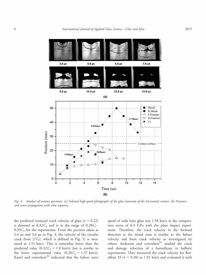
the predicted terminal crack velocity of glass (v = 0.22)is denoted as 0.32CL and is in the range of 0.28CL–0.39CL for the experiments. From the pictures taken at2.6 ls and 3.6 ls in Fig. 4, the velocity of the circularcrack front [(VC), which is defined in Fig. 5] is mea-sured as 1.51 km/s. This is somewhat lower than thepredicted value (0.32CL = 1.8 km/s) but is similar tothe lower experimental value (0.28CL = 1.57 km/s).Kanel and coworkers26 indicated that the failure wave
speed of soda lime glass was 1.58 km/s at the compres-sion stress of 6.3 GPa with the plate impact experi-ment. Therefore, the crack velocity in the forwarddirection at the initial state is similar to the failurevelocity and limit crack velocity as investigated byothers. Anderson and coworkers24 studied the crackand damage velocities of a borosilicate in ballisticexperiments. They measured the crack velocity for Bor-ofloat 33 (m = 0.20) as 1.92 km/s and evaluated it with
Fig. 4. Analysis of contact specimen. (a) Selected high-speed photographs of the glass laminate of the horizontal contact. (b) Fractureand wave propagation with time sequence.
6 International Journal of Applied Glass Science—Choi and Kim 2015
the Rayleigh wave relation, Eq. (3). The predictedvelocities of the crack are in the range of 0.5~0.6 timesthe Rayleigh wave speed.
Brajer et al.27 determined the Rayleigh cone angle(h) using the relation in Eq. (4). They used a speed CR
on the order of 3.3 km/s and a VC value of 1.5 km/sand assessed the theoretical angle to be 28°. However,in our experiments, the surface crack on the impactsurface (★) is observed to propagate faster than theRayleigh wave. The measured speed of the crack, whichfollows the path of the Rayleigh wave propagation inthe time interval between 2.6 ls and 3.6 ls, is4.54 km/s, even though the calculated speed of theRayleigh wave is 3.11 km/s. When a CR of 3.11 km/sand a VC of 1.51 km/s are used, h is calculated as 29°.When the crack velocity measured in the experiments,4.54 km/s, is inserted into Eq. (4), h is calculated tobe 19.4°, which is in better agreement with the experi-mental results than the theoretical calculation. Themeasured cone angles from the experiments are 22° forthe confined specimen shown in Fig. 5 and 19.5° forthe specimen with a free surface. When we considerthose angles in relation with Eq. (4), this reveals thatthe crack grown on the free surface grew faster thanthat on the surface confined with steel blocks.
sinh ¼ VC
CRð4Þ
The Rayleigh cone is generated by the tensile stresswavelets that are formed with the interaction of thelongitudinal wave with the impact surface.21 Abrahamand coworkers28 studied brittle crack propagation bytwo-dimensional molecular dynamic simulation. Theyindicated that mode I (tensile) crack was quickly accel-erated but was limited to the Rayleigh wave speed, con-sistent with the classical theories of fracture. The modeII (shear dominated) crack first accelerated to the Ray-leigh wave speed, propagated at the Rayleigh speed fora while and then jumped to the longitudinal soundspeed. Thus, the cause of the crack on the impact sur-face of EBW loading is considered to be a mixture oftensile and shear stress because the initial crack on theimpact surface grew faster than the speed of the shearwave and propagated slowly later with the loss ofenergy.
Consideration of Acoustic Impedance
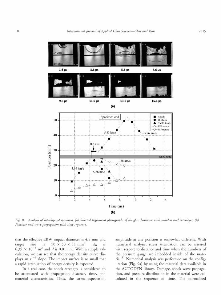
Table III displays the acoustic impedance of mate-rials used in the experiment. Rubber has a very lowvalue compared to glass. Although stainless steel has asimilar sound speed, the value of acoustic impedance isthree times higher than that of glass because the densityis that much higher. Applying Eq. (2) for shock waveinteraction, the amplitude of transmitted stress isrT = 0.20rI and that of reflected stress isrR = �0.80rI at the glass and NBR rubber interface.This means that the majority of the initial stress isreflected as tension at the interface, and only 20% ofthe input stress is transmitted. Thus, the shock wave
Fig. 5. Configuration of crack and wave propagation at 3.6 lsafter EBW detonation.
Table III. Acoustic Impedance of SelectedMaterials
MaterialDensity (q)(g/cm3)
Soundspeed (C)(km/s)
Acousticimpedance(106 kg/m2s)
Soda limeglass
2.50 5.60 14.00
NBRrubber
1.00 1.60 1.60
Stainlesssteel
7.80 5.77 45.03
www.ceramics.org/IJAGS Crack and Shock Propagation 7
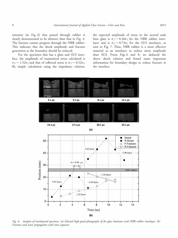
intensity (in Fig. 6) that passed through rubber isclearly demonstrated to be dimmer than that in Fig. 4.The fracture cannot progress through the NBR rubber.This indicates that the shock amplitude and fracturegeneration at the boundary should be reduced.
For the specimen that has a glass and SUS inter-face, the amplitude of transmitted stress calculated isrT = 1.52rI and that of reflected stress is rT = 0.52rI.By simple calculation using the impedance relation,
the expected amplitude of stress in the second sodalime glass is rT = 0.36rI for the NBR rubber inter-layer and is rT = 0.73rI for the SUS interlayer, asseen in Fig. 7. Thus, NBR rubber is a more effectivematerial as an interlayer to reduce stress amplitudethan SUS. From Figs 6 and 8, we deduced theabove shock relation and found some importantinformation for boundary design to reduce fracture atthe interface.
Fig. 6. Analysis of interlayered specimen. (a) Selected high-speed photographs of the glass laminate with NBR rubber interlayer. (b)Fracture and wave propagation with time sequence.
8 International Journal of Applied Glass Science—Choi and Kim 2015
Damage of Glass Laminates with NBR RubberInterlayer
In this experiment, a low-impedance material wasinserted in between relatively high-impedance materials.Due to the low impedance of rubber, there are consid-erable stress wave attenuations, distortions, and reflec-tions. Figure 6 displays a series of high-speedphotographs and wave/fracture locations with respect totime sequence. As wave delay and attenuation wereexpected to occur, the framing time rate of the camerawas changed to 1.5 ls/frame. The shock wave (■)propagates at an initial speed of 5.87 � 0.02 km/s inthe glass, reduces its speed to 2.08 km/s in the NBRrubber, and recovers its speed in the second glass.However, the shock speed is decreased to ~4%, and itsintensity seems to be lower than that of the first glassbecause the transmitted wave is observed to be consid-erably dimmer in the second glass than in the firstglass. There is a discontinuity found in Fig. 6b for theshock propagation data. Although shock wave speedseems to be somewhat decreased after passing throughthe interlayer, it does not depart from the linearityexcept for time delay Dt � 0.96 ls. Comparing Fig. 6with Fig. 4, the shock wave passing through the inter-layer appears dimmer than that of the bulk specimen atthe same propagation distance. The horn-shape crackthat nucleated and grew at the bottom center from14.1 ls is due to tension concentration at a hole forthe M6 screw used to fix the steel block for mechanicalmounting. The fracture growing speed from the impactsurface to the interlayer (D) is nearly the same as thatfrom the interlayer to the impact point (▽).
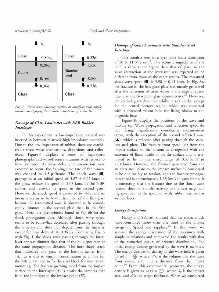
Damage of Glass Laminates with Stainless SteelInterlayer
The stainless steel interlayer plate has a dimensionof 50 9 11 9 2 mm3. The acoustic impedance of theSUS is three times higher than that of glass, so thewave interaction at the interlayer was expected to bedifferent from those of the other results. The measuredshock wave speed (■) is 5.98 � 0.15 km/s. In Fig. 8a,the fracture in the first glass plate was mainly generatedafter the reflection of stress waves at the edge of speci-mens, as the Starphire glass demonstrates.29 However,the second glass does not exhibit many cracks, exceptfor the central bottom region, which was contactedwith a threaded vacant hole for fixing blocks to themagnetic base.
Figure 8b displays the positions of the wave andfracture tip. Wave propagation and reflection speed donot change significantly considering measurementerrors, with the exception of the second reflected wave(▲), which is reflected after passing through the stain-less steel plate. The fracture front speed (M) from theimpact surface to the bottom is changeable with theexistence of flaws inside or on the surface and is esti-mated to be in the speed range of 0.57 km/s to2.01 km/s. However, the fracture generated from thestainless steel plate to the impact surface is consideredto be due mainly to tension, and the fracture propaga-tion speed is approximately 1.38 km/s in each frame. Itis interesting that the fracture due to the shock waverelation does not transfer actively to the next neighbor-ing specimen, as the specimen with rubber was used asan interlayer.
Energy Dissipation
Haney and Subhash showed that the elastic shockwave consumed more than one third of the impactenergy in Spinel and sapphire.29 In this work, weassessed the energy dissipation of the specimen withsimple calculations and compared the results with thatof the numerical results of pressure distribution. Theinitial energy density generated by the wave is w0 ¼ re.The energy dissipation density in the wave field is givenby wðrÞ ¼ dW
dV , where V(r) is the volume that the wavefront swept, and r is a distance from the impactpoint.30 From this experimental geometry, the energydensity is given as wðrÞ ¼ w0A0
prd , where A0 is the impactarea, and d is the target thickness. When we considered
Fig. 7. Stress wave intensity relation at interfaces with simplecalculation applying the acoustic impedance of Table III.
www.ceramics.org/IJAGS Crack and Shock Propagation 9
that the effective EBW impact diameter is 4.5 mm andtarget size is 50 9 50 9 11 mm3, A0 is6.35 9 10�5 m2 and d is 0.011 m. With a simple cal-culation, we can see that the energy density curve dis-plays an r �1 slope. The impact surface is so small thata rapid attenuation of energy density is expected.
In a real case, the shock strength is considered tobe attenuated with propagation distance, time, andmaterial characteristics. Thus, the stress expectation
amplitude at any position is somewhat different. Withnumerical analysis, stress attenuation can be assessedwith respect to distance and time when the numbers ofthe pressure gauge are imbedded inside of the mate-rial.31 Numerical analysis was performed on the config-uration (Fig. 9a) by using the material data available inthe AUTODYN library. Damage, shock wave propaga-tion, and pressure distribution in the material were cal-culated in the sequence of time. The normalized
Fig. 8. Analysis of interlayered specimen. (a) Selected high-speed photographs of the glass laminate with stainless steel interlayer. (b)Fracture and wave propagation with time sequence.
10 International Journal of Applied Glass Science—Choi and Kim 2015
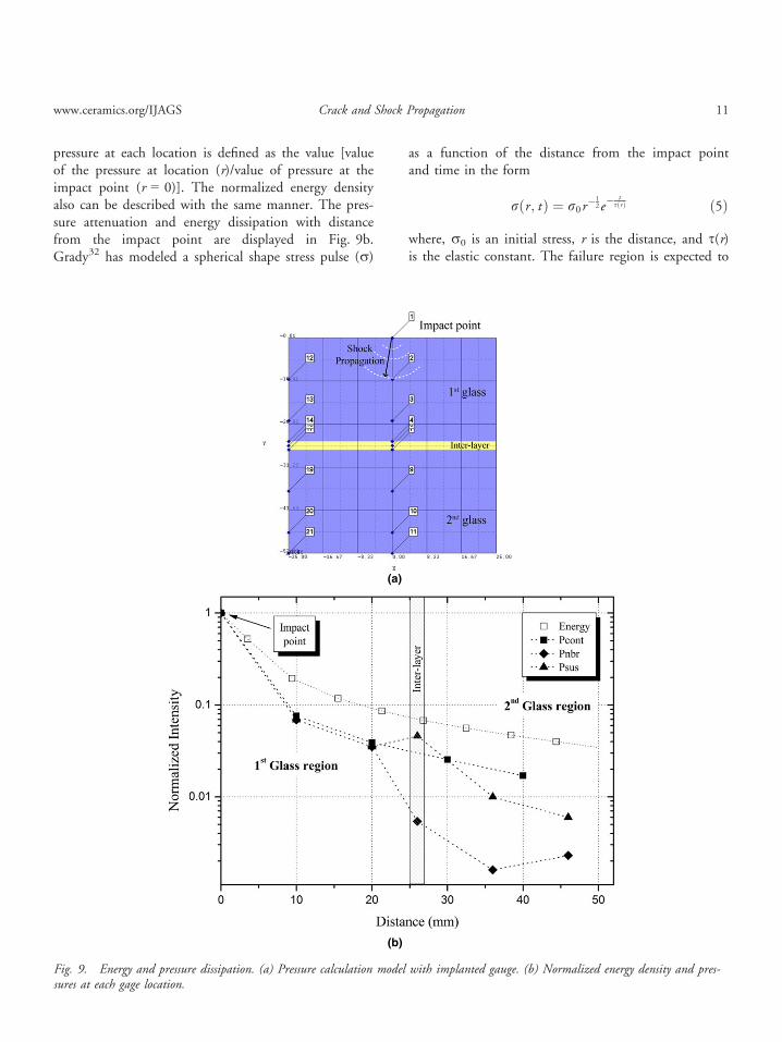
pressure at each location is defined as the value [valueof the pressure at location (r)/value of pressure at theimpact point (r = 0)]. The normalized energy densityalso can be described with the same manner. The pres-sure attenuation and energy dissipation with distancefrom the impact point are displayed in Fig. 9b.Grady32 has modeled a spherical shape stress pulse (r)
as a function of the distance from the impact pointand time in the form
rðr ; t Þ ¼ r0r�1
2e�t
sðrÞ ð5Þ
where, r0 is an initial stress, r is the distance, and s(r)is the elastic constant. The failure region is expected to
(a)
(b)
Fig. 9. Energy and pressure dissipation. (a) Pressure calculation model with implanted gauge. (b) Normalized energy density and pres-sures at each gage location.
www.ceramics.org/IJAGS Crack and Shock Propagation 11
be bounded within a certain region from the impactpoint because stress strength decreased with time anddistance, and eventually, sufficient energy is not pro-vided to grow the crack. When we apply the numericalanalysis results to Eq. (5), the elastic constant (s) isassessed with respect to the propagation distance andtime. It is 1.11 9 10�5 at 10 mm and varies from3.19 9 10�6 at 20 mm to 3.44 9 10�6 at the bottomsurface.
Figure 9b displays the rate change of the energydensity and stress with the propagation distance (r).For the contact specimen (■), stress is attenuated witha pattern similar to the energy curve (□). The pressurerate change in the interlayer is different from that inthe homogeneous block due to impedance mismatch.For an interlayer material of higher impedance thanglass, the stress shows a higher value than that of adja-cent glass (▲). For the NBR interlayer, the stress valuedecreases abruptly (◆) compared with the stress of thehomogeneous block (■). These results match the impe-dance relations in Fig. 7 and fracture patterns observedin-situ and postmortem. For the point impact used inthis study, the impact energy dissipation results in anincrease of volume that is matched to the fracture con-figuration.
Damage Analysis
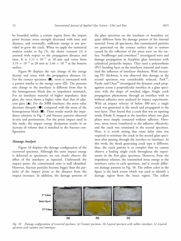
Figure 10 displays the damage configuration of therecovered specimen. Although the same impact energyis delivered to specimens, we can clearly observe theeffect of the interlayer as expected. Underneath theimpact point, the comminuted zone is well identified.However, fracture particles become bigger than the par-ticles of the impact point as the distance from theimpact increases. In addition, the damage patterns of
the glass specimen on the interlayer or boundary arequite different from the damage pattern of the internalmaterial. From all specimens, fine comminuted particlesare generated on the contact surface due to tensioncaused by the reflection of the stress wave on the sur-face. Straßburger and coworkers12 investigated wave anddamage propagation in Starphire glass laminates withcylindrical projectile impact. They used a polyurethane(PU) bonding layer as the interlayer material and exam-ined the influence of interlayer thickness. With increas-ing PU thickness, it was observed that damage in thesecond specimen was considerably reduced. Park33,Parab, and Chen34 investigated the dynamic crack prop-agation across a perpendicular interface in a glass speci-men with the shape of notched edges. Single crackpropagation phenomena through an interface with orwithout adhesive were analyzed by impact experiments.With an impact velocity of below 300 m/s, a singlecrack was generated at the notch and propagated to thenext layer. They found that a crack that was an openingmode (Mode I) stopped at the interface where two glassplates were simply contacted without adhesive. How-ever, stress waves transferred to the adhesive effectively,and the crack was reinitiated in the second specimen.Here, it is worth noting that some delay time wasrequired to reinitiate the crack in the second glass speci-men after passing through the interface or interlayer. Inthis work, the shock generating crack type is different;thus, the crack pattern is so complex that we cannotobserve a leading single crack throughout the experi-ments in the first glass specimen. However, from theimpedance relation, the transmitted stress energy at theinterlayer varies in each specimen, and it reveals differ-ent damage patterns in Fig. 10. The yellow color in thefigure is the back screen which was used to identify adamage region from the intact region. The yellow
Fig. 10. Damage configurations of recovered specimen. (a) Contact specimen. (b) Layered specimen with rubber interlayer. (c) Layeredspecimen with stainless steel interlayer.
12 International Journal of Applied Glass Science—Choi and Kim 2015
region is intact region and the white region and linesare damage region and cracks. As the transmitted stressincreases, more damage and micro-cracks are observed(Fig. 10a). When the input stress is considerably attenu-ated, few long cracks are found in the second glass plate(Fig. 10b). Those cracks were generated not from theinterlayer but from the interface confined with steelblocks. This means that the cause of the crack genera-tion is tensile stress at the interface (Fig. 6a).
Conclusions
The dynamic impact experiment with an EBWloading technique onto glass laminates has been ana-lyzed for its effectiveness in the study of the dynamicfracture behaviors of glass in situ. EBW detonationloads impulse stress onto the specimen of more than 20GPa and causes shock wave interaction in the specimenwithout penetration. The initial speeds of a forwardprogressing fracture and backward fracture are approxi-mately 1.5 km/s, similar to the failure wave and thecrack limit speed of glass at high impact stress. TheRayleigh cone angles of damage are observed to be 22°for the confined specimen and 19.5° for the unconfinedspecimen. The higher the impact stress applied to thespecimen, the faster the Rayleigh surface wave propa-gates, which causes the Rayleigh cone angle to be smal-ler than the angle with lower impact stress.
Analysis of the energy dissipation and impedancerelation at the interlayer reveals that a quantity of<10% of impact energy is transferred to the 2nd glass,and it is matched to the dynamic fracture and the dam-age pattern of the recovered specimen. The impedancerelation at the interlayer plays an important role intransferring stress energy. A low impedance material, asan interlayer, is advantageous to attenuate shock wavesmore effectively than a relatively high impedance mate-rial. The optical density of the shock wave and the frac-ture shape observed on the high-speed photographs arein good agreement with the impedance relation.
References
1. M. M. Shokrieh, and G. H. Javadpour, “Penetration Analysis of a Projec-tile in Ceramic Composite Armor,” Comp. Struct., 82 269–276 (2008).
2. E. Medvedovski, “Ballistic Performance of Armor Ceramics: Influence ofDesign and Structure, Part 2,” Ceram. Int., 36 2117–2127 (2010).
3. E. Straßburger, “Ballistic Testing of Transparent Armor Ceramics,” J. Eur.Ceram. Soc., 29 267–273 (2009).
4. Z. H. Tan, X. Han, W. Zhang, and S. H. Luo, “An Investigation of Fail-ure Mechanism of Ceramic/Metal Armor Subjected to the Impact ofTungsten Projectile,” Int. J. Impact Eng., 37 1162–1169 (2010).
5. R. L. Woodward, W. A. Gooch Jr, R. G. W. J. O’Donnell Perciballi, B.J. Baxter, and S. D. Pattie, “A Sturdy of Fragmentation in the BallisticImpact of Ceramics,” Int. J. Impact Eng., 15 605–618 (1994).
6. E. A. Gamble, B. G. Compton, and F. W. Zok, “Impact Response of Lay-ered Steel-Alumina Targets”, Mech. Mater., 60, 80–92 (2013).
7. D. A. Shockey, A. H. Marchand, S. R. Skaggs, G. E. Cort, M. W. Bur-kett, and R. Parker, “Failure Phenomenology of Confined Ceramic Targetsand Impact Rods”, Int. J. Impact Eng., 9, 263–275 (1990).
8. H. S. Shin, S. N. Chang, and D. K. Kim, “Deformation Behaviors of Zr-Based Bulk Metallic Glass Under Impact Indentation,” Int. J. Mod. Phys.B, 22 1775–1782 (2008).
9. R. B. Leavy, J. D. Clayton, O. E. Strack, R. M. Brannon, and E. Strass-burger, “Edge on Impact Simulation and Experiments,” Procedia Eng., 58445–452 (2013).
10. C. E. Anderson Jr, D. L. Orphal, V. Hohler, M. Moll, and W. Temple-ton, “Failure and Penetration Response of Borosilicate Glass During Short-Rod Impact,” Int. J. Impact. Eng., 36 789–798 (2009).
11. L. C. Forde, W. G. Proud, S. M. Walley, P. D. Curch, and I. G. Cullis,“Ballistic Impact Studies of a Borosilicate Glass,” Int. J. Impact. Eng., 37568–578 (2010).
12. E. Straßburger, and M. Steinhauser, “High speed photographic study ofwave propagation and impact damage in transparent laminates”, ARL-CR-605, 2008.
13. J. H. Choi, and S. N. Chang, “Fracture Phenomena of Brittle Materialagainst a Shaped Charge Jet,” Int. J. Mod. Phys. B, 22 1475–1482 (2008).
14. C. D. Jones, J. B. Rioux, and J. W. Locher, “Advances in ballistic perfor-mance of commercially available Saint-Gobain sapphire transparent armorcomposite”, Advanced in ceramic armor IV, Ceramic Engineering andScience Proceedings, 29 [6] 63–74, 2008.
15. E. Strassburger, P. Patel, W. McCauley, and D. W. Templeton, “Visual-ization of wave propagation and impact damage in a polycrystalline trans-parent ceramic AlON”, Proceedings of 22nd International Symposium onBallistics, Vancouver, Canada, Nov., 2005
16. Soda lime glass (Low-Iron Glass), www.jmcglass.com/down/low.pdf, 2015.17. RP-87 EBW Detonator, P/N 167-9643, RiSi catalog, 27, 2010.18. J. E. Kennedy, “Behavior an Utilization of Explosives in Engineering
Design,” 12th Annual Symposium, ASME, UNIM, Albuquerque, NM,1972.
19. S. P. Marsh, LASL Shock Hugoniot Data, University of California Press,Berkeley, 1980.
20. J. H. Choi, C. H. Lee, and S. N. Chang, “Dynamic fracture phenomenain glass and PMMA”, Proceeding of SPIE 21st High speed photography,Daejon, Korea, August 29–September 2, 1994.
21. M. A. Meyers, Dynamic Behavior of Materials, John Wiley & Sons, Inc.,New York, NY, 1994.
22. E. Straßburger, “Stress wave and damage propagation in transparent lami-nates at elevated temperatures”, U.S. Army Research Laboratory contractorreport ACR-CR-639, 2010.
23. J. Kimberley, and K. T. Ramesh, “Visualization of Early Stage DamagePropagation during Hypervelocity Impacts on Brittle Materials,” ProcediaEng., 58 678–688 (2013).
24. C. E. Anderson Jr, R. P. Bigger, and C. E. Weiss, “Crack and DamageVelocities in Ballistic Experiments,” Int. J. Appl. Glass Sci., 5 374–383(2014).
25. A. Yavari, and H. Khezrzadeh, “Estimating Terminal Velocity of RoughCracks in the Framework of Discrete Fractal Fracture Mechanics,” Eng.Fract. Mech., 77 1516–1526 (2010).
26. G. I. Kanel, S. V. Razorenov, A. S. Savinykh, A. Rajendran, and Z. Chen,“A Study of the Failure Wave Phenomena in Glasses Composed at Differ-ent Levels,” J. Appl. Phys., 98 113523 (2005).
27. X. Brajer, P. Forquin, R. Gy, and F. Hild, “The Role of Surface and Vol-ume Defects in the Fracture of Glass under Quasi-Static and DynamicLoadings,” J. Non-Crys. Solids, 316 42–53 (2003).
www.ceramics.org/IJAGS Crack and Shock Propagation 13
28. F. Abraham, and H. Gao, “How Fast Can Cracks Propagate?” Phys. Rev.Lett., 84 3113–3116 (2000).
29. E. J. Haney, and G. Subhash, “Damage Mechanisms Perspective on Supe-rior Ballistic Performance of Spinel over Sapphire“, Exp. Mech., 53 31–46(2013).
30. H. Senf, and S. Winkler, “Experimental investigation of wave and fracturephenomena in impacted ceramics: Sapphire”, ACR-CR-310, ArmyResearch Laboratory, 1997.
31. J. H. Choi, H. J. Lee, C. H. Lee, and D. K. Kim, “Dynamic FractureBehaviors of Transparent Materials under Detonation Loading”, Proceed-ings of 27th International Symposium on Ballistics, Atlanta, U.S.A.,September 22–26, 2014.
32. D. E. Grady, “Analysis of shock and high-rate data for ceramics: Equationof state properties and fragmentation in the ballistic environment”, AppliedResearch Associates, Inc. ARA Project report L 18637, 2009.
33. H. Park, and W. W. Chen, “Experimental Investigation on DynamicCrack Propagating Perpendicularly through Interface in Glass,” J. Appl.Mech., 78 051013 (2011).
34. N. D. Parab, and W. W. Chen, “Crack Propagation through Interfaces ina Borosilicate Glass and Glass Ceramic”, Int. J. Glass Sci.., 5 353–362(2014).
14 International Journal of Applied Glass Science—Choi and Kim 2015