Embed Size (px)
Citation preview
© 2014 IAU, Arak Branch. All rights reserved.
Journal of Solid Mechanics Vol. 6, No. 4 (2014) pp. 410-421
Crack Interaction Studies Using XFEM Technique
K. Sharma*
Reactor Safety Divison, Bhabha Atomic Research Centre, Trombay, Mumbai, 400085, India
Received 1 August 2014; accepted 7 October 2014
ABSTRACT
In this paper, edge crack problems under mechanical loads have been analysed using extended finite element method (XFEM) as it has proved to be a competent method for handling problems with discontinuities. The XFEM provides a versatile technique to model discontinuities in the solution domain without re-meshing or conformal mesh. The stress intensity factors (SIF) have been calculated by domain based interaction integral method. The effect of crack orientation and interaction under mechanical loading has been studied. Analytical solutions, which are available for two dimensional displacement fields in linear elastic fracture mechanics, have been used for crack tip enrichment. From the present analysis, it has been observed that there is monotonous decrease in the SIF-1 value with the increase in inclination, while SIF-II values first increases then it also decreases. Next study was performed for first edge crack in the presence of second crack on opposite edge. The results were obtained by changing the distance between the crack tips as well as by changing the orientation of second crack. SIFs values decrease with increase in distances between the crack tips for collinear cracks. In next study, for the first crack in presence of inclined second edge crack and it was found that SIFs increase initially with the increase in inclination and decrease after that. It emphasizes the fact that cracks at larger distances act more or less independently. In next study, with the use of level set method crack growth path is evaluated without remeshing for plate with hole, soft inclusion & hard inclusion under mode-I loading and compare with available published results.
© 2014 IAU, Arak Branch. All rights reserved.
Keywords: XFEM; Crack interaction; Fracture mechanics.
1 INTRODUCTION
ANY structural systems, which are comprised of piping systems, can be found in nuclear power plants, off-shore drilling platforms, fossil power generation plants, gas pipelines and others. The unavoidable existence of
cracks in some components may lead to increased safety concerns about the loss of structural strength and possibly failure of these structural systems. In assessing the integrity of structures containing such cracks, it is important to quantify the relevant crack driving force so that its load-carrying capacity can be predicted. As opposed to earlier FE approaches, in recent years the X-FEM has proven to be a very efficient tool for the numerical modeling of cracks. In comparison to the standard FEM, the X-FEM provides significant benefits in the numerical modeling of crack propagation. The main advantages are that the finite element mesh need not to conform to the crack boundaries (crack faces) to account for the geometric discontinuity, and furthermore, mesh regeneration is not needed in crack growth simulations. Therefore, only a single mesh, which is often easily generated, can be used for any crack length
______ * Corresponding author. E-mail address: [email protected] (K. Sharma).
M
411 K. Sharma
© 2014 IAU, Arak Branch
and orientation. The X-FEM is based on the introduction of additional degrees of freedom (DOFs), which are associated with the nodes of the elements intersected by the crack geometry. In this method, both discontinuous displacement fields along the crack faces and the leading singular crack tip asymptotic displacement fields are added to the displacement based FEM approximation for crack modeling through the partition of unity approach. This enables the method for accurate modeling of the crack.
2 REVIEW OF EARLIER WORK
Numerical methods, especially the finite element (FE) method, have been widely used in computational fracture mechanics. However, modeling of multiple crack configurations, crack growth and cracks intersecting with other discontinuities is still a laborious task since the crack topology is generally complicated and difficult to be explicitly modeled by the FE. Moreover, the crack tip singularity needs to be accurately represented by the approximation. Belytschko and Black [1] introduced a method for solving crack problems in the FE framework which is independent of the mesh. In this method, the meshing task is reduced by enriching the elements near the crack tip and along the crack faces with the leading singular crack tip asymptotic displacement fields using the partition of unity (PU) method [2, 3] to account for the presence of the crack. When multiple crack segments are needed to be enriched with the near tip fields, a mapping algorithm introduced by Fleming et al. [4] is used to align the discontinuity with the crack geometry. They also proved that the use of discontinuous displacements along the crack produces a solution with zero traction along the crack faces. Moës et al. [5] introduced a much more elegant and straightforward procedure to introduce a discontinuous field across the crack faces away from the crack tip by adapting the generalized Heaviside function, and developed simple rules for the introduction of the discontinuous and crack tip enrichments. Later, Daux et al. [6] introduced the junction function concept to account for multiple branched cracks and named their method the extended Finite Element Method (XFEM). They have employed this method for modeling complicated geometries such as multiple branched cracks, voids and cracks emanating from holes without the need for the geometric entities to be meshed. Sukumar et al. [7] studied planar mode I cracks in three dimensions with the XFEM. Dolbow et al. [8] studied fracture in Mindlin–Reissner plates, and 2D crack growth under three different interfacial constitutive laws on the crack faces: perfect contact and unilateral contact with or without friction [9]. Areias and Belytschko [10] have applied the XFEM to study the crack initiation and propagation in 3-D space. A formulation based on viscosity-regularized continuum damage constitutive model has been coupled with the XFEM formulation. Nagashima et al. [11] explored the application of XFEM for the stress analyses of structures having interface cracks between dissimilar materials. Liu et al. [12] improved XFEM by enriching the FEM approximation with the higher order terms of crack tip asymptotic field using a partition of unity. The crack faces behind the tip were modeled independently by displacement jump functions. Sukumar et al. [13] have described and presented the modelling of holes and inclusions by level sets in XFEM. Alves and Rossi [14] have presented a method to combine the element free Galerkin method with the extended partition of unity finite element method. Afterwards, more investigations have been carried out by researchers such as Sukumar and Prévost [15] and Sukumar et al. [16] for modeling quasi-static crack growth, Zi and Belytschko [17] and Mergheim et al. [18] for modeling cohesive cracks and Sukumar and Hunag [19] for modeling bimaterial interface cracks.
3 REVIEW OF XFEM
Numerical methods, in XFEM, an n-dimensional domain, ΩЄRn is considered, which is discretized by n elements numbered from 1 to n while I is the set of all nodes in the domain. Then the enriched displacement trial and test approximation for the vector function uh with the partition of unity enrichment takes the general form:
4
1 1r
A
nh
I I I II I n
I n
u N u H a b
x x x x
(1)
Crack Interaction Studies Using XFEM Technique 412
© 2014 IAU, Arak Branch
where NI(x) is element shape function associated with node I satisfying the partition of unity criterion. uI is the nodal displacement vector associated with the continuous part of the finite element solution, aI is the nodal enriched degree of freedom associated with the Heaviside (discontinuous) function H(x) for elements through which the crack passes. bI
is the nodal enriched degree of freedom vector associated with the elastic asymptotic crack tip functions. In the above equation, n is the set of all nodes in the mesh; nr is the set of nodes whose shape function is cut by the crack face and na is the set of nodes whose shape function support is cut by the crack tip.
The standard displacements do not correspond to the displacements computed by XFEM. Thus, a shifted enrichment is used. If xi is the node of interest then Eq. (1) can be written as:
4
11
[ ( ) ( )]
( ) ( )[ ( ) ( )]
r
A
i i i
i nn
hi
i ii
i n
Η H
N
u x x a
u x xx x b
(2)
In Eq. (2), the difference between the values of the enrichment function at the evaluation point (Gauss point in
the present simulations) and nodal point is considered. This modification also preserves the partition of unity property of the shape function.
3.1 Discontinuous enrichment for crack face
The discontinuity in the displacement due to the presence of a crack is modeled by a generalized Heaviside function H(x). The discontinuous enrichment or Heaviside function for the purpose of computation can be abbreviated as:
1 ( ) 0( )
1
ifH
otherwise
xx
(3)
where ψ(x) is the level set function.
3.2 Asymptotic enrichment for crack tip
To model the crack front and also to improve the representation of crack tip fields in computations, crack tip enrichment functions are used in elements which contain a crack tip. The enrichment consists of functions which incorporate the radial and angular behavior of the two dimensional asymptotic crack tip displacement field. These functions are given as:
1 2 3 4( ) , , , cos , sin , cos sin , sin sin2 2 2 2
r r r r
x
In the above expression, r and θ are the local coordinates of the crack tip.
3.3 Level set method
Level set is defined by a scalar function within the domain, where a zero level is interpreted as the discontinuity. As a consequence, the domain is divided into two sub-domains and on either side of the discontinuity where the level set function is positive or negative respectively. Two dimensional domain with the circular discontinuity of radius (0,0)r , is described. Then, the discontinuity may be defined by the level set
function 2 2, x y rx y , where 0 on the circle. Also, the signed distance function is used as a
particular level set function and is depicted as under:
413 K. Sharma
© 2014 IAU, Arak Branch
ˆmin . .x x x sign n x x x
A single crack in two dimensions is considered as a strong discontinuity. Let c be the interior of the crack
(crack faces) and 1 2i i x be the crack tips. The definition of the signed-distance function to the curve c is
given by:
min* *
min*
ˆ, . 0
, otherwise
c c c
c c c
d
d
2x x x x x x x ex
x x x x x
(4)
where, ., .d is the usual Euclidean distance on 2 , *x the point closest to x on the crack c with cx any point
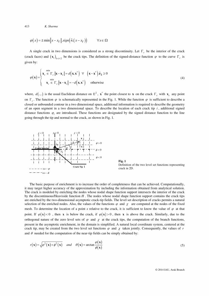
on c . The function is schematically represented in the Fig. 1. While the function is sufficient to describe a closed or unbounded contour in a two dimensional space, additional information is required to describe the geometry of an open segment in a two dimensional space. To describe the location of each crack tip i , additional signed distance functions i are introduced. These functions are designated by the signed distance function to the line going through the tip and normal to the crack, as shown in Fig. 1.
Fig. 1 Definition of the two level set functions representing crack in 2D.
The basic purpose of enrichment is to increase the order of completeness that can be achieved. Computationally,
it may target higher accuracy of the approximation by including the information obtained from analytical solution. The crack is modeled by enriching the nodes whose nodal shape function support intersects the interior of the crack by the discontinuous/Heaviside function H . The nodes whose nodal shape function support contains the crack tips are enriched by the two-dimensional asymptotic crack-tip fields. The level set description of cracks permits a natural selection of the enriched nodes. Also, the values of the functions and are computed at the nodes of the fixed mesh. To determine the location of a point x relative to the crack, it is sufficient to know the value of at that
point. If 0 x , then x is below the crack, if 0 x , then x is above the crack. Similarly, due to the
orthogonal nature of the zero level sets of and at the crack tips, the computation of the branch functions, present in the asymptotic enrichment, in the domain is simplified. A natural local coordinate system, centered at the crack tip, may be created from the two level set functions and taken jointly. Consequently, the values of r and needed for the computation of the near-tip fields can be simply obtained by:
2 2 arctanr and
x
x x x xx
(5)
1e
2e r
x
*x
Crack Tip i
Crack Interior
0
0
0
0 0 0
iso—
iso—
Crack Interaction Studies Using XFEM Technique 414
© 2014 IAU, Arak Branch
The selection of enriched nodes is also simplified by the use of the level set functions and . Let, min and
max (correspondingly, min and max ) be the respective minimum and maximum values of (correspondingly of ) at the nodes of a given element. For an element to contain the crack tip, the necessary and sufficient conditions
are min max 0 and min max 0 . Also, the necessary condition for the crack to completely intercept an element is if and only if the value of function at the nodes of the element is both positive and negative i.e.
min max 0 and the function is negative i.e. 0 at all of its nodes.
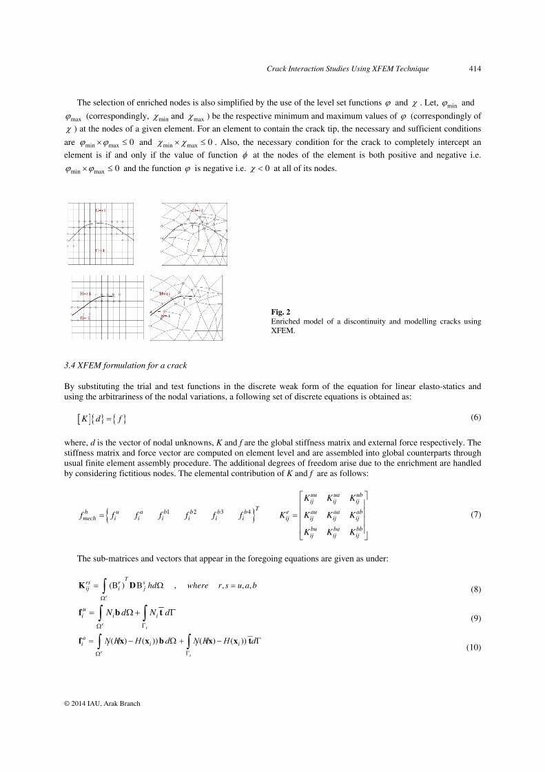
Fig. 2 Enriched model of a discontinuity and modelling cracks using XFEM.
3.4 XFEM formulation for a crack
By substituting the trial and test functions in the discrete weak form of the equation for linear elasto-statics and using the arbitrariness of the nodal variations, a following set of discrete equations is obtained as:
K d f (6)
where, d is the vector of nodal unknowns, K and f are the global stiffness matrix and external force respectively. The stiffness matrix and force vector are computed on element level and are assembled into global counterparts through usual finite element assembly procedure. The additional degrees of freedom arise due to the enrichment are handled by considering fictitious nodes. The elemental contribution of K and f are as follows:
1 2 3 4
uu ua ubij ij ij
Th u a b b b b e au aa abmech i i i i i i ij ij ij ij
bu ba bbij ij ij
K K K
f f f f f f f K K K K
K K K
(7)
The sub-matrices and vectors that appear in the foregoing equations are given as under:
( ) , , , ,e
Trs r sij i j hd where r s u a b
K D
(8)
et
ui i iN d N d
f b t (9)
( ( ) ( )) ( ( ) ( ))e
t
ai i i i iΝ Η H d Ν Η H d
f x x b x x t (10)
415 K. Sharma
© 2014 IAU, Arak Branch
0
10
20
30
40
50
60
70
80
0 10 20 30 40 50 60 70 80
Edge crack inclination (deg)
Str
esss
in
ten
sity
fac
tor
(K-1
& K
-2) K-1
K-2
(( ) ( )) ( ( ) ( )) , , 1,2,3,4e
t
bαi i i i iN d N d where
f x x b x x t (11)
where, Ni are finite element shape function, Bi
u, Bia, Bi
b and Bib are the matrices of shape function derivatives given
by:
,,
, ,
, ,, 3 8 ,
1 2 3 4
,
,
( ( ) ( ))0 0
0 , 0 ( ( ) ( ))
( ( ) ( )) ( ( ) ( ))
,
( ( ) ( )) 0
0 ( (
( ( ) ( ))
i i xi xu ai i y i i i y
i y i i yi x i i x
b b b b bi i i i i
i i xbi i
i i y
N H HΝ
Ν N H H
Ν N H HΝ N H H
Ν
Ν
Ν
x x
x xx x x x
x x
xx x
,
, 3 8
) ( ))
( ( ) ( ))
1,2,3, 4
i y
i i xΝ
x
x x
The formulations for holes and inclusions are similar as for the cracks. Enrichment may be seen as adding extra
degrees of freedom to the enriched nodes. An enriched node gains one extra degree of freedom per enrichment function per dimension. In 2D, a node for which the displacement fields are enriched with the four crack tip asymptotic enrichment functions, for instance, has two conventional degrees of freedom (its displacements in both directions) and 2*4=8 enrichment degrees of freedom.
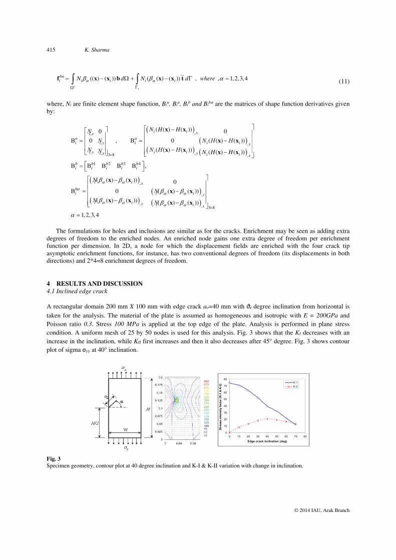
4 RESULTS AND DISCUSSION 4.1 Inclined edge crack
A rectangular domain 200 mm X 100 mm with edge crack ao=40 mm with θc degree inclination from horizontal is taken for the analysis. The material of the plate is assumed as homogeneous and isotropic with E = 200GPa and Poisson ratio 0.3. Stress 100 MPa is applied at the top edge of the plate. Analysis is performed in plane stress condition. A uniform mesh of 25 by 50 nodes is used for this analysis. Fig. 3 shows that the KI decreases with an increase in the inclination, while KII first increases and then it also decreases after 45° degree. Fig. 3 shows contour plot of sigma σyy at 40° inclination.
Fig. 3 Specimen geometry, contour plot at 40 degree inclination and K-I & K-II variation with change in inclination.
Crack Interaction Studies Using XFEM Technique 416
© 2014 IAU, Arak Branch
0
10
20
30
40
50
60
70
80
0 10 20 30 40 50 60 70
Offset distance (mm)
Str
esss
inte
nsi
ty fac
tor
(K-1
& K
-2)
K-1
K-2
0
10
20
30
40
50
60
70
80
0 10 20 30 40 50 60 70
Second edge crack inclination (deg)
Str
esss
inte
nsi
ty f
acto
r (K
-1 &
K-2
)
K-1
K-2
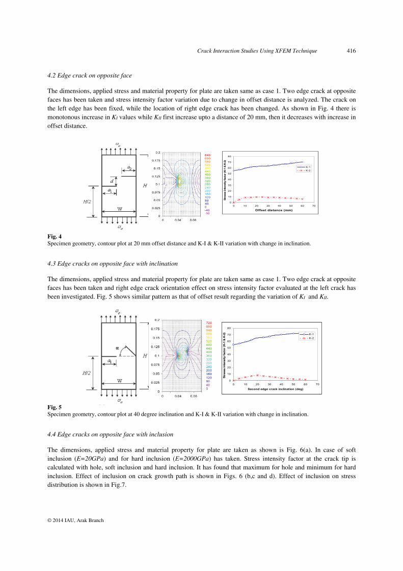
4.2 Edge crack on opposite face
The dimensions, applied stress and material property for plate are taken same as case 1. Two edge crack at opposite faces has been taken and stress intensity factor variation due to change in offset distance is analyzed. The crack on the left edge has been fixed, while the location of right edge crack has been changed. As shown in Fig. 4 there is monotonous increase in KI values while KII first increase upto a distance of 20 mm, then it decreases with increase in offset distance.
Fig. 4 Specimen geometry, contour plot at 20 mm offset distance and K-I & K-II variation with change in inclination.
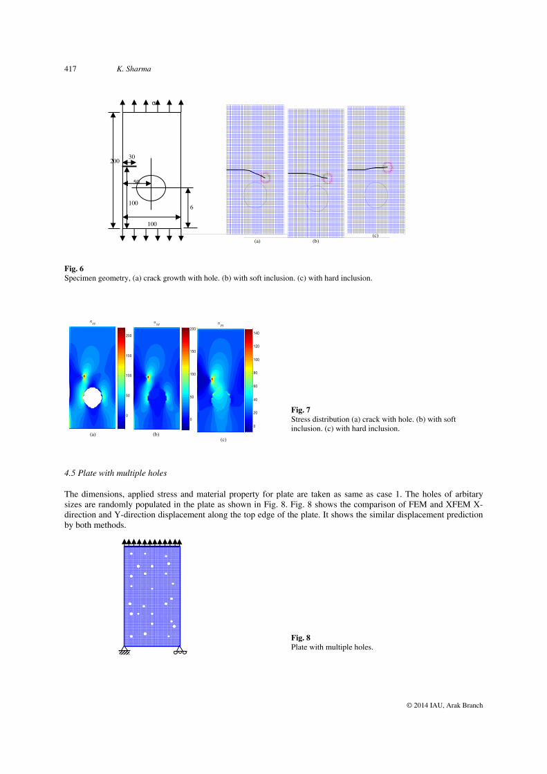
4.3 Edge cracks on opposite face with inclination
The dimensions, applied stress and material property for plate are taken same as case 1. Two edge crack at opposite faces has been taken and right edge crack orientation effect on stress intensity factor evaluated at the left crack has been investigated. Fig. 5 shows similar pattern as that of offset result regarding the variation of KI and KII.
Fig. 5 Specimen geometry, contour plot at 40 degree inclination and K-I & K-II variation with change in inclination.
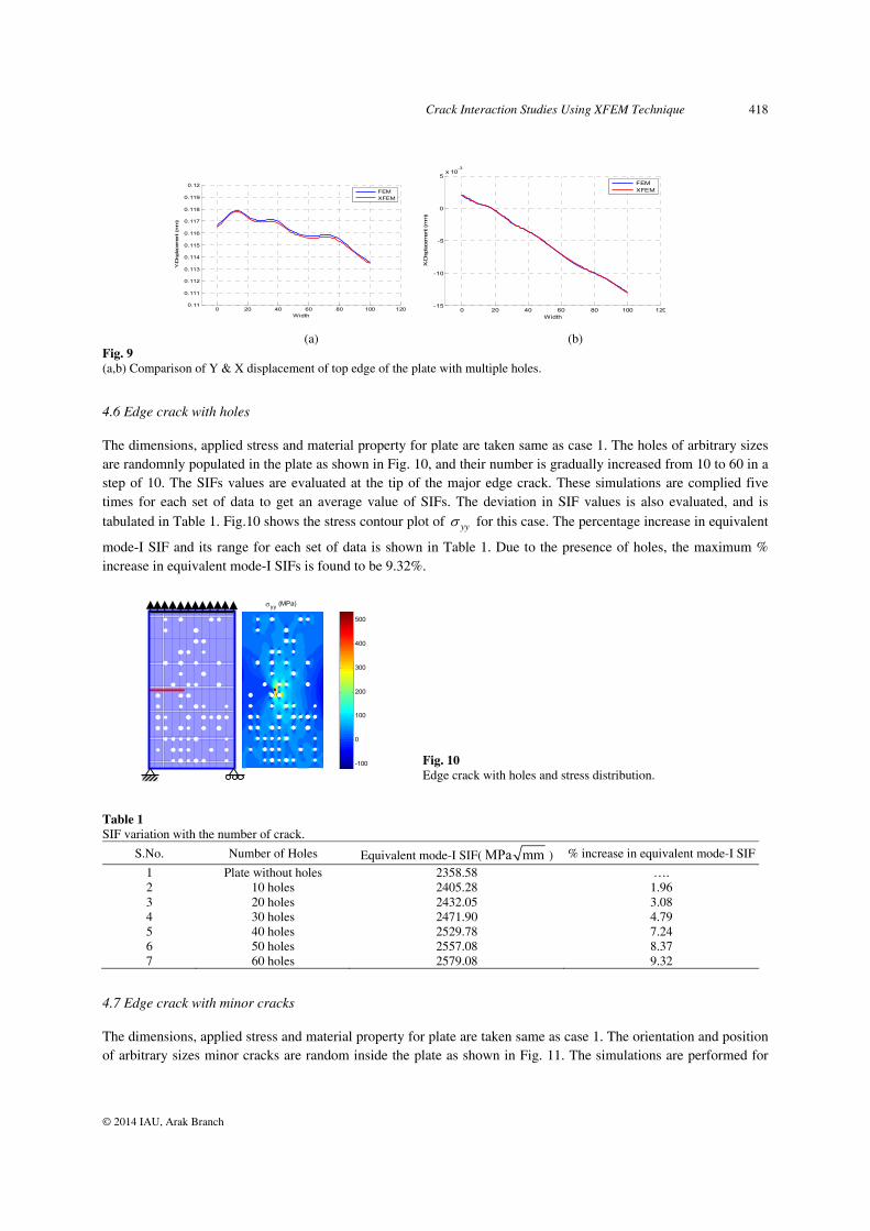
4.4 Edge cracks on opposite face with inclusion
The dimensions, applied stress and material property for plate are taken as shown is Fig. 6(a). In case of soft inclusion (E=20GPa) and for hard inclusion (E=2000GPa) has taken. Stress intensity factor at the crack tip is calculated with hole, soft inclusion and hard inclusion. It has found that maximum for hole and minimum for hard inclusion. Effect of inclusion on crack growth path is shown in Figs. 6 (b,c and d). Effect of inclusion on stress distribution is shown in Fig.7.
417 K. Sharma
© 2014 IAU, Arak Branch
Fig. 6 Specimen geometry, (a) crack growth with hole. (b) with soft inclusion. (c) with hard inclusion.
Fig. 7 Stress distribution (a) crack with hole. (b) with soft inclusion. (c) with hard inclusion.
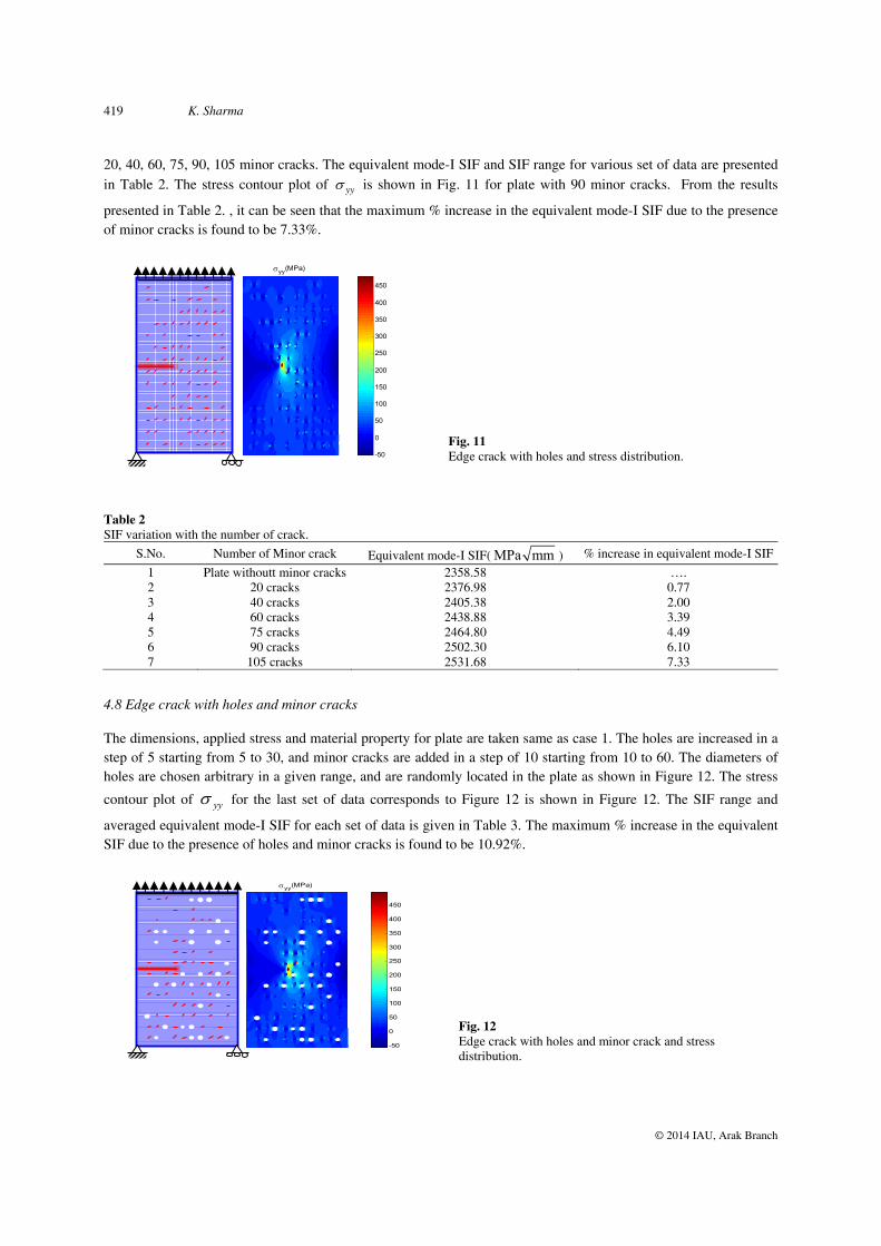
4.5 Plate with multiple holes
The dimensions, applied stress and material property for plate are taken as same as case 1. The holes of arbitary sizes are randomly populated in the plate as shown in Fig. 8. Fig. 8 shows the comparison of FEM and XFEM X-direction and Y-direction displacement along the top edge of the plate. It shows the similar displacement prediction by both methods.
Fig. 8 Plate with multiple holes.
50
6
σ
200
100
100
30
(a) (b)(c)
(a)
yy
0
50
100
150
200
0
50
100
150
200
yy yy
0
20
40
60
80
100
120
140
(b) (c)
Crack Interaction Studies Using XFEM Technique 418
© 2014 IAU, Arak Branch
(a) (b) Fig. 9 (a,b) Comparison of Y & X displacement of top edge of the plate with multiple holes.
4.6 Edge crack with holes
The dimensions, applied stress and material property for plate are taken same as case 1. The holes of arbitrary sizes are randomnly populated in the plate as shown in Fig. 10, and their number is gradually increased from 10 to 60 in a step of 10. The SIFs values are evaluated at the tip of the major edge crack. These simulations are complied five times for each set of data to get an average value of SIFs. The deviation in SIF values is also evaluated, and is tabulated in Table 1. Fig.10 shows the stress contour plot of yy for this case. The percentage increase in equivalent
mode-I SIF and its range for each set of data is shown in Table 1. Due to the presence of holes, the maximum % increase in equivalent mode-I SIFs is found to be 9.32%.
Fig. 10 Edge crack with holes and stress distribution.
Table 1 SIF variation with the number of crack.
S.No. Number of Holes Equivalent mode-I SIF( MPa mm ) % increase in equivalent mode-I SIF
1 Plate without holes 2358.58 …. 2 10 holes 2405.28 1.96 3 20 holes 2432.05 3.08 4 30 holes 2471.90 4.79 5 40 holes 2529.78 7.24 6 50 holes 2557.08 8.37 7 60 holes 2579.08 9.32
4.7 Edge crack with minor cracks
The dimensions, applied stress and material property for plate are taken same as case 1. The orientation and position of arbitrary sizes minor cracks are random inside the plate as shown in Fig. 11. The simulations are performed for
0 20 40 60 80 100 1200.11
0.111
0.112
0.113
0.114
0.115
0.116
0.117
0.118
0.119
0.12
Y-D
ispl
ace
ment
(m
m)
Width
FEMXFEM
0 20 40 60 80 100 120-15
-10
-5
0
5x 10
-3
X-D
ispl
acem
ent
(m
m)
Width
FEMXFEM
yy (MPa)
-100
0
100
200
300
400
500
419 K. Sharma
© 2014 IAU, Arak Branch
20, 40, 60, 75, 90, 105 minor cracks. The equivalent mode-I SIF and SIF range for various set of data are presented in Table 2. The stress contour plot of yy is shown in Fig. 11 for plate with 90 minor cracks. From the results
presented in Table 2. , it can be seen that the maximum % increase in the equivalent mode-I SIF due to the presence of minor cracks is found to be 7.33%.
Fig. 11 Edge crack with holes and stress distribution.
Table 2 SIF variation with the number of crack.
S.No. Number of Minor crack Equivalent mode-I SIF( MPa mm ) % increase in equivalent mode-I SIF
1 Plate withoutt minor cracks 2358.58 …. 2 20 cracks 2376.98 0.77 3 40 cracks 2405.38 2.00 4 60 cracks 2438.88 3.39 5 75 cracks 2464.80 4.49 6 90 cracks 2502.30 6.10 7 105 cracks 2531.68 7.33
4.8 Edge crack with holes and minor cracks
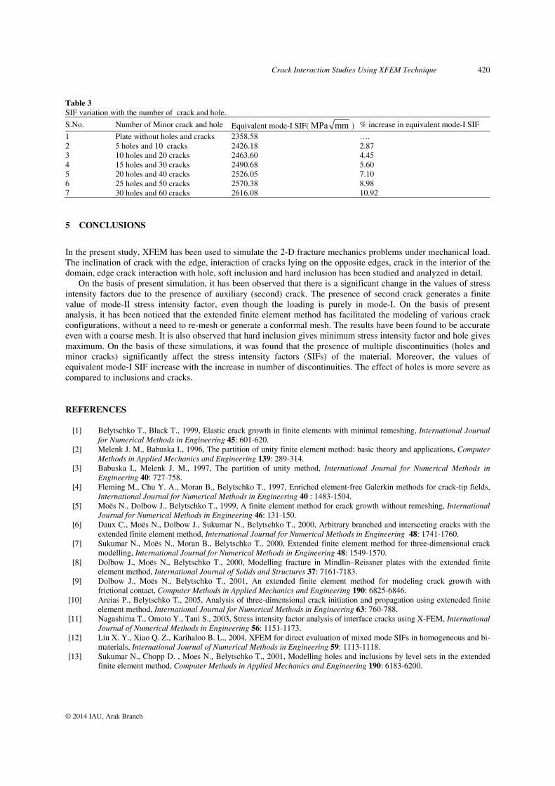
The dimensions, applied stress and material property for plate are taken same as case 1. The holes are increased in a step of 5 starting from 5 to 30, and minor cracks are added in a step of 10 starting from 10 to 60. The diameters of holes are chosen arbitrary in a given range, and are randomly located in the plate as shown in Figure 12. The stress
contour plot of yy for the last set of data corresponds to Figure 12 is shown in Figure 12. The SIF range and
averaged equivalent mode-I SIF for each set of data is given in Table 3. The maximum % increase in the equivalent SIF due to the presence of holes and minor cracks is found to be 10.92%.
Fig. 12 Edge crack with holes and minor crack and stress distribution.
yy(MPa)
-50
0
50
100
150
200
250
300
350
400
450
yy(MPa)
-50
0
50
100
150
200
250
300
350
400
450
Crack Interaction Studies Using XFEM Technique 420
© 2014 IAU, Arak Branch
Table 3 SIF variation with the number of crack and hole. S.No. Number of Minor crack and hole Equivalent mode-I SIF( MPa mm ) % increase in equivalent mode-I SIF
1 Plate without holes and cracks 2358.58 …. 2 5 holes and 10 cracks 2426.18 2.87 3 10 holes and 20 cracks 2463.60 4.45 4 15 holes and 30 cracks 2490.68 5.60 5 20 holes and 40 cracks 2526.05 7.10 6 25 holes and 50 cracks 2570.38 8.98 7 30 holes and 60 cracks 2616.08 10.92
5 CONCLUSIONS
In the present study, XFEM has been used to simulate the 2-D fracture mechanics problems under mechanical load. The inclination of crack with the edge, interaction of cracks lying on the opposite edges, crack in the interior of the domain, edge crack interaction with hole, soft inclusion and hard inclusion has been studied and analyzed in detail.
On the basis of present simulation, it has been observed that there is a significant change in the values of stress intensity factors due to the presence of auxiliary (second) crack. The presence of second crack generates a finite value of mode-II stress intensity factor, even though the loading is purely in mode-I. On the basis of present analysis, it has been noticed that the extended finite element method has facilitated the modeling of various crack configurations, without a need to re-mesh or generate a conformal mesh. The results have been found to be accurate even with a coarse mesh. It is also observed that hard inclusion gives minimum stress intensity factor and hole gives maximum. On the basis of these simulations, it was found that the presence of multiple discontinuities (holes and minor cracks) significantly affect the stress intensity factors (SIFs) of the material. Moreover, the values of equivalent mode-I SIF increase with the increase in number of discontinuities. The effect of holes is more severe as compared to inclusions and cracks.
REFERENCES
[1] Belytschko T., Black T., 1999, Elastic crack growth in finite elements with minimal remeshing, International Journal for Numerical Methods in Engineering 45: 601-620.
[2] Melenk J. M., Babuska I., 1996, The partition of unity finite element method: basic theory and applications, Computer Methods in Applied Mechanics and Engineering 139: 289-314.
[3] Babuska I., Melenk J. M., 1997, The partition of unity method, International Journal for Numerical Methods in Engineering 40: 727-758.
[4] Fleming M., Chu Y. A., Moran B., Belytschko T., 1997, Enriched element-free Galerkin methods for crack-tip fields, International Journal for Numerical Methods in Engineering 40 : 1483-1504.
[5] Moës N., Dolbow J., Belytschko T., 1999, A finite element method for crack growth without remeshing, International Journal for Numerical Methods in Engineering 46: 131-150.
[6] Daux C., Moës N., Dolbow J., Sukumar N., Belytschko T., 2000, Arbitrary branched and intersecting cracks with the extended finite element method, International Journal for Numerical Methods in Engineering 48: 1741-1760.
[7] Sukumar N., Moës N., Moran B., Belytschko T., 2000, Extended finite element method for three-dimensional crack modelling, International Journal for Numerical Methods in Engineering 48: 1549-1570.
[8] Dolbow J., Moës N., Belytschko T., 2000, Modelling fracture in Mindlin–Reissner plates with the extended finite element method, International Journal of Solids and Structures 37: 7161-7183.
[9] Dolbow J., Moës N., Belytschko T., 2001, An extended finite element method for modeling crack growth with frictional contact, Computer Methods in Applied Mechanics and Engineering 190: 6825-6846.
[10] Areias P., Belytschko T., 2005, Analysis of three-dimensional crack initiation and propagation using exteneded finite element method, International Journal for Numerical Methods in Engineering 63: 760-788.
[11] Nagashima T., Omoto Y., Tani S., 2003, Stress intensity factor analysis of interface cracks using X-FEM, International Journal of Numerical Methods in Engineering 56: 1151-1173.
[12] Liu X. Y., Xiao Q. Z., Karihaloo B. L., 2004, XFEM for direct evaluation of mixed mode SIFs in homogeneous and bi-materials, International Journal of Numerical Methods in Engineering 59: 1113-1118.
[13] Sukumar N., Chopp D. , Moes N., Belytschko T., 2001, Modelling holes and inclusions by level sets in the extended finite element method, Computer Methods in Applied Mechanics and Engineering 190: 6183-6200.
421 K. Sharma
© 2014 IAU, Arak Branch
[14] Alves M., Rossi R., 2003, A modidied element-free galerkin method with essential boundary conditions enforced by an extended partition of unity finite element weight function, International Journal for Numerical Methods in Engineering 57 : 1523-1552.
[15] Sukumar N., Prévost J. H., 2003, Modelling quasi-static crack growth with the extended finite element method Part I: Computer implementation, International Journal of Solids and Structures 40: 7513-7537.
[16] Huang R., Sukumar N., Prévost J. H. , 2003, Modeling quasi-static crack growth with the extended finite element method Part II: Numerical applications, International Journal of Solids and Structures 40: 7539-7552.
[17] Zi G., Belytschko T., 2003, New crack-tip elements for XFEM and applications to cohesive cracks, International Journal for Numerical Methods in Engineering 57: 2221-2240.
[18] Mergheim J., Kuhl E., Steinmann P., 2005, A finite element method for the computational modelling of cohesive cracks, International Journal for Numerical Methods in Engineering 63: 276-289.
[19] Sukumar N., Huang Z. Y., Prévost J. H., Suo Z., 2004, Partition of unity enrichment for bimaterial interface cracks, International Journal for Numerical Methods in Engineering 59: 1075-1102.

![A hybrid XFEM - Phase Field (Xfield) method for crack … · 2016. 11. 10. · A hybrid XFEM - Phase Field (Xfield) method for crack propagation in brittle materials BIANCA GIOVANARDI],](https://img.pdfslide.net/doc/110x75/614a978a12c9616cbc69840e/a-hybrid-xfem-phase-field-xfield-method-for-crack-2016-11-10-a-hybrid-xfem.jpg)

![A hybrid XFEM - Phase Field (Xfield) method for crack ... · A hybrid XFEM - Phase Field (Xfield) method for crack propagation in brittle materials BIANCA GIOVANARDI], ANNA SCOTTI](https://img.pdfslide.net/doc/110x75/5ade1d027f8b9a595f8db44e/a-hybrid-xfem-phase-field-xfield-method-for-crack-hybrid-xfem-phase-field.jpg)


![An XFEM method for modelling geometrically elaborate crack ...pages.cs.wisc.edu/~sifakis/papers/crack_propagation_xfem_preprint.pdfIn [6] Moes, et. al., used XFEM to create a technique](https://img.pdfslide.net/doc/110x75/5f01e3527e708231d40186ba/an-xfem-method-for-modelling-geometrically-elaborate-crack-pagescswiscedusifakispaperscrackpropagationxfem.jpg)
![An XFEM method for modeling geometrically elaborate crack ... · AN XFEM METHOD FOR GEOMETRICALLY ELABORATE CRACK PROPAGATION 3 for holes and inclusions see [24]) and has also been](https://img.pdfslide.net/doc/110x75/5ad9bedd7f8b9a53618bac1b/an-xfem-method-for-modeling-geometrically-elaborate-crack-xfem-method-for-geometrically.jpg)