Embed Size (px)
Citation preview
Security Notes
RSA Algorithm explained
(Crptography)
Copyright 2010 Rishabh Dangwal
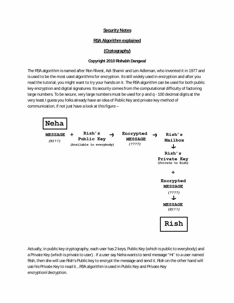
The RSA algorithm is named after Ron Rivest, Adi Shamir and Len Adleman, who invented it in 1977 and is used to be the most used algorithms for encryption. Its still widely used in encryption and after you read the tutorial, you might want to try your hands on it. The RSA algorithm can be used for both public key encryption and digital signatures. Its security comes from the computational difficulty of factoring large numbers. To be secure, very large numbers must be used for p and q - 100 decimal digits at the very least.I guess you folks already have an idea of Public Key and private key method of communication, if not just have a look at this figure –
Actually, in public key cryptography, each user has 2 keys, Public Key (which is public to everybody) and a Private Key (which is private to user) . If a user say Neha wants to send message “Hi” to a user named Rish, then she will use Rish’s Public key to encrypt the message and send it, Rish on the other hand will use his Private Key to read it...RSA algorithm is used in Public Key and Private Key encryption/decryption.
Enough talk...Now lets have a look how RSA algorithm works...
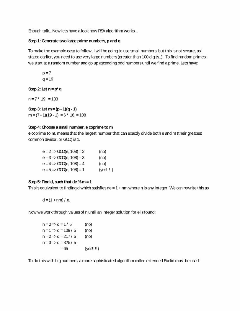
Step 1: Generate two large prime numbers, p and q
To make the example easy to follow, I will be going to use small numbers, but this is not secure, as I stated earlier, you need to use very large numbers (greater than 100 digits..) . To find random primes, we start at a random number and go up ascending odd numbers until we find a prime. Lets have:
p = 7 q = 19
Step 2: Let n = p*q
n = 7 * 19 = 133
Step 3: Let m = (p - 1)(q - 1) m = (7 - 1)(19 - 1) = 6 * 18 = 108 Step 4: Choose a small number, e coprime to m e coprime to m, means that the largest number that can exactly divide both e and m (their greatest common divisor, or GCD) is 1.
e = 2 => GCD(e, 108) = 2 (no) e = 3 => GCD(e, 108) = 3 (no) e = 4 => GCD(e, 108) = 4 (no) e = 5 => GCD(e, 108) = 1 (yes!!!!)
Step 5: Find d, such that de % m = 1 This is equivalent to finding d which satisfies de = 1 + nm where n is any integer. We can rewrite this as
d = (1 + nm) / e.
Now we work through values of n until an integer solution for e is found:
n = 0 => d = 1 / 5 (no) n = 1 => d = 109 / 5 (no) n = 2 => d = 217 / 5 (no) n = 3 => d = 325 / 5 = 65 (yes!!!!)
To do this with big numbers, a more sophisticated algorithm called extended Euclid must be used.
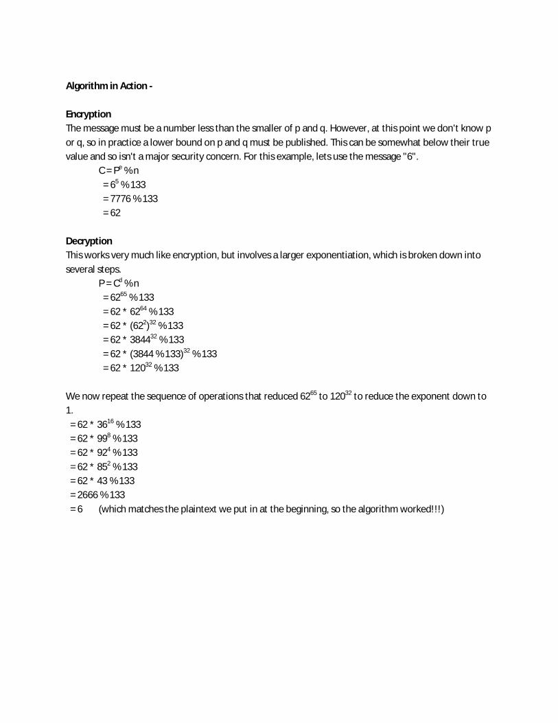
Algorithm in Action - Encryption The message must be a number less than the smaller of p and q. However, at this point we don't know p or q, so in practice a lower bound on p and q must be published. This can be somewhat below their true value and so isn't a major security concern. For this example, lets use the message "6".
C = Pe % n = 65 % 133 = 7776 % 133 = 62
Decryption This works very much like encryption, but involves a larger exponentiation, which is broken down into several steps.
P = Cd % n = 6265 % 133 = 62 * 6264 % 133 = 62 * (622)32 % 133 = 62 * 384432 % 133 = 62 * (3844 % 133)32 % 133 = 62 * 12032 % 133
We now repeat the sequence of operations that reduced 6265 to 12032 to reduce the exponent down to 1. = 62 * 3616 % 133 = 62 * 998 % 133 = 62 * 924 % 133 = 62 * 852 % 133 = 62 * 43 % 133 = 2666 % 133 = 6 (which matches the plaintext we put in at the beginning, so the algorithm worked!!!)

REVERSE ENGINEERING What is Reverse Code Engineering? "Reverse engineering (RE) is the process of discovering the technological principles of a mechanical application through analysis of its structure, function and operation" Basically, Reverse Code Engineering (RCE) is the application of the reverse engineering process to software - in other words, analyzing a program in order to understand how it works. Reverse engineering is largely focused on the Windows platform as its mostly used to analyse closed source programs; however, reversing under Linux is also popular for inspecting buffer overflows, closed-source Linux applications, and hostile Windows programs (without the risk of running them). Why Reverse Engineer? Reasons ?!!
Have you ever wished that your favorite Windows program had abc functionality?
Want to dissect malware or viruses?
Look for and analyze a buffer overflow?
Want to check out how that hardware driver works so you can write one for Linux? (Geeks only :D )
Or you are just curious about that software..
And much much more
Why Reverse Engineer? This article focuses on building basic knowledge about Reverse Engineering by explaining basics of Assembly and CPU registers...A must read for Reverse Engineering/ Cracking enthusiastic. How Does It Work? This all sounds great, but how do we analyze a program for which we have no code? There are many ways to observe how a program interacts with the rest of your system, such as file and registry access (which can be helpful when reverse engineering), but these techniques still leave you with a black box - you don't know what is going on under the hood. In order to understand how we can analyze the internal workings of a program, some understanding of the compilation process is needed. When you compile your source code, there are three major steps that occur: translation of the source code into assembly code, assembly, and linking. First, the source code is translated into assembly code by the compiler. Assembly is a very low-level programming language; it is composed of many simple instructions which deal directly with memory addresses and CPU registers. For instance, if you assign the number 1 to an integer variable in your source code, the resulting assembly code may look something like:
mov 0xffffffb4,0x1 which moves the number 1 into 0xffffffb4, the memory address assigned to that particular variable. No matter what programming language you are using (C/C++, Delphi, VB, etc), all compiled languages must

be first translated into assembly before being converted into the final binary program. Next, an assembler translates the assembly code into machine-readable code; there is (usually) a one-to-one translation between the assembly and machine code. The final stage is performed by a linker, whose job it is to add in any library functions required by the program. The final result is a file that contains binary instructions which can be executed by the processor. The point of all this is that since all programs are translated into assembly code, and assembly code can be translated directly into binary 1s and 0s, we can translate any binary program back into its assembly code through the aptly named process of disassembly. If you understand assembly code, you can follow the instructions to understand what the program is doing, and even translate it into a higher-level language such as C. Note that some languages can be automatically translated directly back into their original source code, or decompiled. While this process works well for some languages, it is generally very complex and imprecise for most programming languages, particularly C/C++ Opposition to RCE It is important to realize that for various reasons, people may not want you to reverse engineer their programs, and as such, they may implement encryption or advanced protection techniques which make it extremely hard to analyze the original assembly code. We will certainly not be covering these techniques in this paper, but it is good to keep in mind if you come across a disassembled program that doesn't seem to make any sense. A second issue is the legality of RCE. Many EULAs prohibit reverse engineering, but this still may not make it necessarily illegal; like many digital laws, it is still somewhat undefined. However, I will quote the following from Exploiting Software:
These agreements [EULAs] usually contain language that strictly prohibits reverse engineering. However, these agreements may or may not hold up in court [Kaner and Pels, 1998]. The Uniform Computer Information Transactions Act (UCITA) poses strong restrictions on reverse engineering and may be used to help "click through" EULA's stand-up in court. Some states have adopted the UCITA (Maryland and Virginia as of this writing [February 2004]), which strongly affects your ability to reverse engineer legally.
Normally, there is no need to fear RE-restrictive laws, unless you plan to publicize your work. One exception would be cracking, or using reverse engineering to circumvent an application's registration scheme, which is very illegal. All programs we will be working with in this paper are original, so there is no question of legality; however, it is very important to keep this in mind if you begin work on someone else's programs.
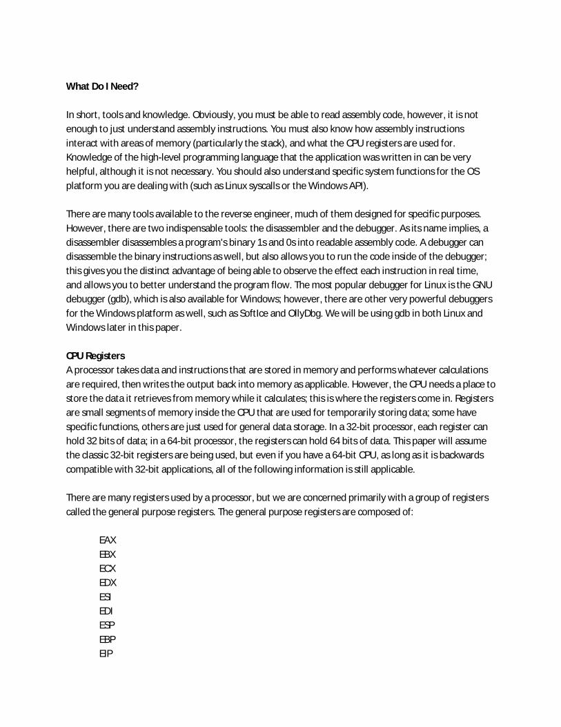
What Do I Need? In short, tools and knowledge. Obviously, you must be able to read assembly code, however, it is not enough to just understand assembly instructions. You must also know how assembly instructions interact with areas of memory (particularly the stack), and what the CPU registers are used for. Knowledge of the high-level programming language that the application was written in can be very helpful, although it is not necessary. You should also understand specific system functions for the OS platform you are dealing with (such as Linux syscalls or the Windows API). There are many tools available to the reverse engineer, much of them designed for specific purposes. However, there are two indispensable tools: the disassembler and the debugger. As its name implies, a disassembler disassembles a program's binary 1s and 0s into readable assembly code. A debugger can disassemble the binary instructions as well, but also allows you to run the code inside of the debugger; this gives you the distinct advantage of being able to observe the effect each instruction in real time, and allows you to better understand the program flow. The most popular debugger for Linux is the GNU debugger (gdb), which is also available for Windows; however, there are other very powerful debuggers for the Windows platform as well, such as SoftIce and OllyDbg. We will be using gdb in both Linux and Windows later in this paper. CPU Registers A processor takes data and instructions that are stored in memory and performs whatever calculations are required, then writes the output back into memory as applicable. However, the CPU needs a place to store the data it retrieves from memory while it calculates; this is where the registers come in. Registers are small segments of memory inside the CPU that are used for temporarily storing data; some have specific functions, others are just used for general data storage. In a 32-bit processor, each register can hold 32 bits of data; in a 64-bit processor, the registers can hold 64 bits of data. This paper will assume the classic 32-bit registers are being used, but even if you have a 64-bit CPU, as long as it is backwards compatible with 32-bit applications, all of the following information is still applicable. There are many registers used by a processor, but we are concerned primarily with a group of registers called the general purpose registers. The general purpose registers are composed of:
EAX EBX ECX EDX ESI EDI ESP EBP EIP

The EAX register is called the accumulator, and is commonly used to hold the results of a calculation. If a function returns a value, this value will be placed in the EAX register so that the code that called the function can access the return value. EBX is a pointer to the data segment, and ECX is normally used to count the number of iterations in a loop; EDX is used as an I/O pointer. It is important to note that while these are the suggested functions of the EAX, EBX, ECX and EDX registers, they are not restricted to these uses, with a few exceptions. For example, EAX can be used to hold data regardless of whether or not that data is the result of some calculation; however, if a function returns a value, that value will always be stored in the EAX register. ESI and EDI are used to specify source and destination addresses respectively; they are most often used when copying strings from one memory address to another. ESP is a stack register, called a stack pointer, that points to the top of the stack; EBP is also a stack register (called the base pointer), used to reference local variables and function arguments on the stack. The exact purpose and usage of the ESP and EBP registers will be clarified in the following sections. EIP is the instruction pointer register - it controls program execution by pointing to the address of the next instruction to be executed. For example, if your program calls a function that is located at the address of 0x08ffff1d, the value stored in EIP will be changed to that address so that the CPU knows where to go in order to execute the first instruction of that function. Note that there is no way to directly control the value stored in EIP. The 'E' at the beginning of each register name stands for Extended. When a register is referred to by its extended name, it indicates that all 32 bits of the register are being addressed. An interesting thing about registers is that they can be broken down into smaller subsets of themselves; the first sixteen bits of each register can be referenced by simply removing the 'E' from the name. For instance, if you wanted to only manipulate the first sixteen bits of the EAX register, you would refer to it as the AX register. Additionally, registers AX through DX can be further broken down into two eight bit parts. So, if you wanted to manipulate only the first eight bits (bits 0-7) of the AX register, you would refer to the register as AL; if you wanted to manipulate the last eight bits (bits 8-15) of the AX register, you would refer to the register as AH ('L' standing for Low and 'H' standing for High).

Process Memory and the Stack Often, a process will need to deal with more data than there are available registers. To remedy this, each process running in memory has what is referred to as a stack. The stack is simply an area of memory which the process uses to store data such as local variables, command line/function arguments, and return addresses. Before examining the stack in detail, let's take a look at how a process is generally arranged in memory:
High Memory Addresses (0xFFFFFFFF) ---------------------- <-----Bottom of the stack | | | | | | Stack | | Stack grows down | | v | | |---------------------| <----Top of the stack (ESP points here) | | | | | | | | | | |---------------------| <----Top of the heap | | | | ^ | Heap | | Heap grows up | | | | | |---------------------| <-----Bottom of the heap | | | Instructions | | | | | ----------------------- Low Memory Addresses (0x00000000)
As you can see, there are three main sections of memory: 1. Stack Section - Where the stack is located, stores local variables and function arguments. 2. Data Section - Where the heap is located, stores static and dynamic variables. 3. Code Section - Where the actual program instructions are located.
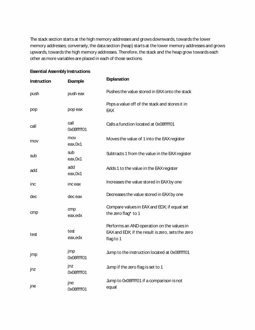
The stack section starts at the high memory addresses and grows downwards, towards the lower memory addresses; conversely, the data section (heap) starts at the lower memory addresses and grows upwards, towards the high memory addresses. Therefore, the stack and the heap grow towards each other as more variables are placed in each of those sections. Essential Assembly Instructions
Instruction Example Explanation
push push eax Pushes the value stored in EAX onto the stack
pop pop eax Pops a value off of the stack and stores it in EAX
call call 0x08ffff01
Calls a function located at 0x08ffff01
mov mov eax,0x1
Moves the value of 1 into the EAX register
sub sub eax,0x1
Subtracts 1 from the value in the EAX register
add add eax,0x1
Adds 1 to the value in the EAX register
inc inc eax Increases the value stored in EAX by one
dec dec eax Decreases the value stored in EAX by one
cmp cmp eax,edx
Compare values in EAX and EDX; if equal set the zero flag* to 1
test test eax,edx
Performs an AND operation on the values in EAX and EDX; if the result is zero, sets the zero flag to 1
jmp jmp 0x08ffff01
Jump to the instruction located at 0x08ffff01
jnz jnz 0x08ffff01
Jump if the zero flag is set to 1
jne jne 0x08ffff01
Jump to 0x08ffff01 if a comparison is not equal

and and eax,ebx
Performs a bitwise AND operation on the values stored in EAX and EBX; the result is saved in EAX
or or eax,ebx
Performs a bitwise OR operation on the values stored in EAX and EBX; the result is saved in EAX
xor xor eax,eax
Performs a bitwise XOR operation on the values stored in EAX and EBX; the result is saved in EAX
leave leave Remove data from the stack before returning
ret ret Return to a parent function
nop nop No operation (a 'do nothing' instruction)
*The zero flag (ZF) is a 1 bit indicator which records the result of a cmp or test instruction Each instruction performs one specific task, and can deal directly with registers, memory addresses, and the contents thereof. It is easiest to understand exactly what these functions are used for when seen in the context of a simple hello world program, which we will do a little bit later. Assembly syntax There are two types of syntax used in assembly code: Intel and AT&T. Each display thesame instructions, just a little bit differently (in the above examples I have used Intel syntax). The primary difference is that the source and destination operands are flip-flopped. Look at the differences in how the syntaxes display the instruction to move the number 1 into the EAX register:
Intel Syntax: mov eax, 0x1 AT&T Syntax: mov $0x1,%eax
Besides the source (the number 1) and the destination (the EAX register) being reversed, the AT&T syntax also adds a percent sign in front of all register names and a dollar sign in front of hexadecimal numbers. Regardless of syntax however, it is still the same instruction. You should be familiar with both syntaxes, as different disassemblers may use either one or the other syntax when disassembling a program. For my following examples I will be using the Intel syntax since it is a little easier to understand; however, the GNU debugger (gdb), which we will be using later in this paper, uses AT&T syntax. As such, I will be supplying both the AT&T and Intel versions of the sample programs in order to give exposure to both syntaxes.
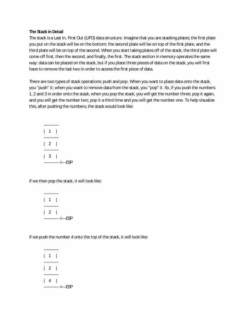
The Stack in Detail The stack is a Last In, First Out (LIFO) data structure. Imagine that you are stacking plates; the first plate you put on the stack will be on the bottom; the second plate will be on top of the first plate, and the third plate will be on top of the second. When you start taking plates off of the stack, the third plate will come off first, then the second, and finally, the first. The stack section in memory operates the same way: data can be placed on the stack, but if you place three pieces of data on the stack, you will first have to remove the last two in order to access the first piece of data. There are two types of stack operations: push and pop. When you want to place data onto the stack, you "push" it; when you want to remove data from the stack, you "pop" it. So, if you push the numbers 1, 2 and 3 in order onto the stack, when you pop the stack, you will get the number three; pop it again, and you will get the number two; pop it a third time and you will get the number one. To help visualize this, after pushing the numbers, the stack would look like:
----------- | 1 | ----------- | 2 | ----------- | 3 | ----------- <---ESP
If we then pop the stack, it will look like:
----------- | 1 | ----------- | 2 | ----------- <---ESP
If we push the number 4 onto the top of the stack, it will look like:
----------- | 1 | ----------- | 2 | ----------- | 4 | ----------- <---ESP
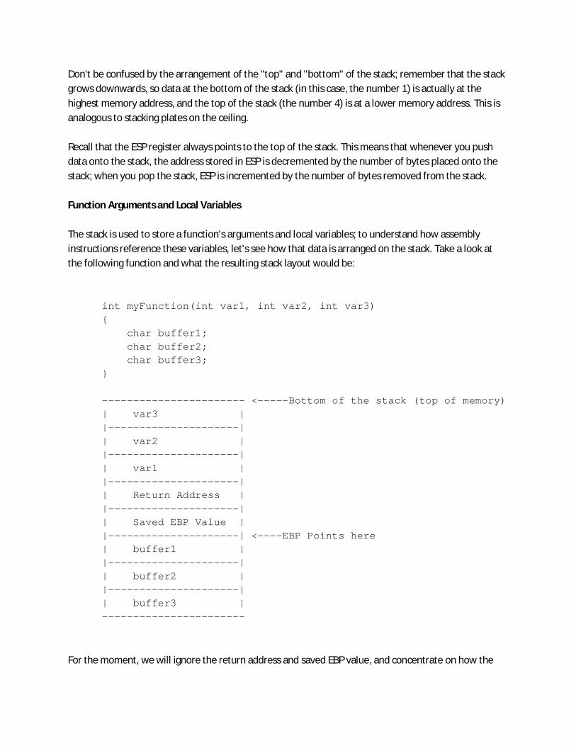
Don't be confused by the arrangement of the "top" and "bottom" of the stack; remember that the stack grows downwards, so data at the bottom of the stack (in this case, the number 1) is actually at the highest memory address, and the top of the stack (the number 4) is at a lower memory address. This is analogous to stacking plates on the ceiling. Recall that the ESP register always points to the top of the stack. This means that whenever you push data onto the stack, the address stored in ESP is decremented by the number of bytes placed onto the stack; when you pop the stack, ESP is incremented by the number of bytes removed from the stack. Function Arguments and Local Variables The stack is used to store a function's arguments and local variables; to understand how assembly instructions reference these variables, let's see how that data is arranged on the stack. Take a look at the following function and what the resulting stack layout would be:
int myFunction(int var1, int var2, int var3) { char buffer1; char buffer2; char buffer3; } ----------------------- <-----Bottom of the stack (top of memory) | var3 | |---------------------| | var2 | |---------------------| | var1 | |---------------------| | Return Address | |---------------------| | Saved EBP Value | |---------------------| <----EBP Points here | buffer1 | |---------------------| | buffer2 | |---------------------| | buffer3 | -----------------------
For the moment, we will ignore the return address and saved EBP value, and concentrate on how the

arguments and variables get placed onto the stack. Before a function is called, all of its arguments must first be placed on the stack. These arguments are pushed onto the stack in reverse order; that is, in our example, var3 would be pushed first, var2 second, and finally var1: push var3 push var2 push var1 call myFunction The call instruction will automatically place the return value onto the stack, and the saved EBP value is pushed immediately afterwards by myFunction (again, we are ignoring these values for now - more on them later). Then, the local variables are pushed onto the stack in the order which they are declared; first buffer1, then buffer2, and lastly buffer3. When you look at the assembly code of a disassembled program however, you won't have nice names for variables like var1 or buffer1; instead they will be indicated by memory addresses, or as offsets from EBP (recall that the purpose of EBP is to reference variables on the stack). Since the function arguments are located at higher memory addresses than the address pointed to by EBP, they will be referenced as positive offsets from EBP (example: 'ebp+8'); local variables, being located at lower memory addresses, will be referenced as negative offsets from EBP (example: 'ebp-4'). So, whenever you see something referenced as an offset from EBP, you know that you are dealing with a local variable. Conclusion I guess what you covered along the workshop will be supplemented by this basic knowledge of Assembly language,if you really want to crack programs, you can practice live examples using ollydbg and softice, but legally, we cant provide concrete notes on reverse engineering.