Embed Size (px)
Citation preview
AS 2550.1—2011
Australian Standard®
Cranes, hoists and winches—Safe use
Part 1: General requirements
AS
2
55
0.1
—2
01
1
This Australian Standard® was prepared by Committee ME-005, Cranes. It was approved on behalf of the Council of Standards Australia on 19 January 2011. This Standard was published on 18 March 2011.
The following are represented on Committee ME-005:
• Australian Chamber of Commerce and Industry • Australian Industry Group • Australian Institute for Non-Destructive Testing • Bureau of Steel Manufacturers of Australia • Construction and Mining Equipment Industry Group • Consult Australia • Crane Association of New Zealand • Crane Industry Council of Australia • Department of Commerce, WorkSafe Division (WA) • Department of Justice and Attorney General, Qld • Department of Labour New Zealand • Department of the Premier and Cabinet (South Australia) • Electricity Engineers Association (New Zealand) • Elevating Work Platform Association of Australia • Engineers Australia • Horticulture New Zealand • Industry and Investment NSW • Institution of Professional Engineers New Zealand • Vehicle Loading Crane Interests • WorkCover New South Wales • WorkSafe Victoria
This Standard was issued in draft form for comment as DR AS 2550.1. Standards Australia wishes to acknowledge the participation of the expert individuals that contributed to the development of this Standard through their representation on the Committee and through the public comment period.
Keeping Standards up-to-date Australian Standards® are living documents that reflect progress in science, technology and systems. To maintain their currency, all Standards are periodically reviewed, and new editions are published. Between editions, amendments may be issued. Standards may also be withdrawn. It is important that readers assure themselves they are using a current Standard, which should include any amendments that may have been published since the Standard was published. Detailed information about Australian Standards, drafts, amendments and new projects can be found by visiting www.standards.org.au Standards Australia welcomes suggestions for improvements, and encourages readers to notify us immediately of any apparent inaccuracies or ambiguities. Contact us via email at [email protected], or write to Standards Australia, GPO Box 476, Sydney, NSW 2001.
AS 2550.1—2011
Australian Standard®
Cranes, hoists and winches—Safe use
Part 1: General requirements
Originated as part of AS 2550—1982.
Revised and redesignated in part as AS 2550.1—1993.
Second edition 2002.
Third edition 2011.
COPYRIGHT
© Standards Australia Limited
All rights are reserved. No part of this work may be reproduced or copied in any form or by
any means, electronic or mechanical, including photocopying, without the written
permission of the publisher, unless otherwise permitted under the Copyright Act 1968.
Published by SAI Global Limited under licence from Standards Australia Limited, GPO Box
476, Sydney, NSW 2001, Australia
ISBN 978 0 7337 9786 6
AS 2550.1—2011 2
PREFACE
This Standard was prepared by the Australian members of the Joint Standards
Australia/Standards New Zealand Committee ME-005, Cranes, to supersede
AS 2550.1—2002, Cranes, hoists and winches—Safe use, Part 1: General.
After consultation with stakeholders in both countries, Standards Australia and Standards
New Zealand decided to retain this Standard as an Australian Standard rather than develop
it as an Australian/New Zealand Standard.
The objective of this Standard is to specify general requirements for the safe use of cranes,
hoists and winches.
The objective of the AS 2550 series of Standards is to provide uniform requirements and
guidance for the safe use of cranes, hoists and winches.
Major changes in this Edition include extensive revision of the inspection and maintenance
requirements in Section 7, and the addition of a new Section 9 that specifies methods to
monitor design duty and introduce the concept of design working period. Section 9 of this
Standard is based on the concepts outlined in ISO 12482-1, Cranes condition monitoring,
Part 1: General.
Published Standards in the series are the following:
AS
2550 Cranes, hoists and winches—Safe use
2550.1 Part 1: General requirements (this Standard)
2550.3 Part 3: Bridge, gantry, portal (including container cranes) jib and monorail
cranes
2550.4 Part 4: Tower cranes
2550.5 Part 5: Mobile cranes
2550.6 Part 6: Guided storing and retrieving appliances
2550.7 Part 7: Builders’ hoists and associated equipment
2550.9 Part 9: Vehicle hoists
2550.10 Part 10: Elevating work platforms
2550.11 Part 11 Vehicle loading cranes
2550.13 Part 13: Building maintenance units
2550.15 Part 15: Concrete placing equipment
2550.16 Part 16: Mast climbing work platforms
2550.19 Part 19: Telescopic handlers
2550.20 Part 20: Self-erecting tower cranes
Statements expressed in mandatory terms in notes to tables are deemed to be requirements
of this Standard.
The terms ‘normative’ and ‘informative’ have been used in this Standard to define the
application of the appendix to which they apply. A ‘normative’ appendix is an integral part
of a Standard, whereas an ‘informative’ appendix is only for information and guidance.
3 AS 2550.1—2011
CONTENTS
Page
SECTION 1 SCOPE AND GENERAL
1.1 SCOPE ........................................................................................................................ 5
1.2 APPLICATION ........................................................................................................... 5
1.3 REFERENCED DOCUMENTS .................................................................................. 5
1.4 DEFINITIONS ............................................................................................................ 6
1.5 INSTRUCTIONS ........................................................................................................ 7
1.6 LEGISLATED RESPONSIBILITY............................................................................. 7
1.7 COMPETENCY OF PERSONNEL............................................................................. 7
1.8 RISK ASSESSMENT.................................................................................................. 8
SECTION 2 PLANNING
2.1 GENERAL .................................................................................................................. 9
2.2 PLANNING................................................................................................................. 9
2.3 MATTERS TO BE CONSIDERED........................................................................... 10
SECTION 3 SELECTION...................................................................................................... 11
SECTION 4 SITING
4.1 GENERAL ................................................................................................................ 12
4.2 CRANE STANDING................................................................................................. 12
4.3 PROXIMITY HAZARDS AND VISIBILITY ........................................................... 13
4.4 ENVIRONMENTAL RESTRICTIONS..................................................................... 13
4.5 CLEARANCES ......................................................................................................... 13
SECTION 5 ERECTION, COMMISSIONING AND DISMANTLING
5.1 IDENTIFICATION OF CRANE COMPONENTS .................................................... 14
5.2 ERECTION, COMMISSIONING AND DISMANTLING INSTRUCTIONS ........... 14
5.3 ELECTRICAL SUPPLY ........................................................................................... 14
5.4 COMMISSIONING................................................................................................... 14
5.5 SAFEGUARDING THE CRANE.............................................................................. 14
SECTION 6 OPERATION
6.1 OPERATIONAL INSTRUCTIONS .......................................................................... 15
6.2 CRANE-OPERATION MANAGEMENT ................................................................. 16
6.3 COMPLIANCE WITH INSTRUCTIONS ................................................................. 17
6.4 COMMUNICATION OF IRREGULARITIES .......................................................... 17
6.5 LEAVING THE CRANE UNATTENDED ............................................................... 17
6.6 OUT OF SERVICE ................................................................................................... 17
6.7 HOUSEKEEPING ..................................................................................................... 17
6.8 CRANE ACCESS AND EGRESS............................................................................. 18
6.9 PERSONS APPROACHING THE PROXIMITY OF A CRANE .............................. 18
6.10 CRANE OPERATION .............................................................................................. 18
6.11 LOAD SECURITY.................................................................................................... 20
6.12 CONTROL OF LOAD............................................................................................... 20
6.13 TAG LINES............................................................................................................... 20
6.14 COMMUNICATION................................................................................................. 20
6.15 HANDLING LOADS OVER PUBLIC ACCESS AREAS AND ADJACENT
BUILDINGS.............................................................................................................. 22
6.16 NON-POSITIVE LIFTING ATTACHMENTS.......................................................... 23
AS 2550.1—2011 4
6.17 INDICATING AND LIMITING DEVICES .............................................................. 23
6.18 RIDING ON THE CRANE STRUCTURE ................................................................ 23
6.19 SUSPENSION OF PERSONS BY CRANE............................................................... 23
6.20 OPERATION NEAR AERIAL CONDUCTORS (OVERHEAD POWERLINES) .... 25
6.21 UNDERGROUND CONDUCTOR CONTACT ........................................................ 29
6.22 SPECIAL DUTIES .................................................................................................... 30
6.23 WEATHER CONDITIONS....................................................................................... 31
6.24 INCIDENT OR DAMAGE........................................................................................ 31
6.25 MODIFICATIONS TO CRANES ............................................................................. 32
6.26 FIRE EXTINGUISHER............................................................................................. 32
6.27 DESIGNED LIFTS.................................................................................................... 32
6.28 MULTIPLE HOIST OR CRANE OPERATION ....................................................... 33
6.29 MANUALS ............................................................................................................... 35
6.30 VESSEL-MOUNTED CRANES ............................................................................... 36
SECTION 7 MAINTENANCE, INSPECTION AND REPAIR
7.1 GENERAL ................................................................................................................ 39
7.2 MAINTENANCE ...................................................................................................... 40
7.3 INSPECTION............................................................................................................ 40
7.4 REPAIRS................................................................................................................... 43
7.5 RECORDS................................................................................................................. 45
SECTION 8 INSPECTION OF ROPES, HOOKS AND LIFTING GEAR
8.1 ROPES ...................................................................................................................... 46
8.2 HOOKS AND HOOK BLOCKS ............................................................................... 47
8.3 LIFTING GEAR........................................................................................................ 48
SECTION 9 MAJOR ASSESSMENT FOR CONTINUED USE OR CHANGED
OPERATION
9.1 GENERAL ................................................................................................................ 49
9.2 RECORDING OF CRANE OPERATION................................................................. 49
9.3 ASSESSMENT OF DESIGN WORKING PERIOD.................................................. 50
9.4 MAJOR ASSESSMENT............................................................................................ 51
9.5 GENERAL OVERHAUL .......................................................................................... 52
9.6 DWP CALCULATION FOR CRANES..................................................................... 52
9.7 DWP CALCULATION FOR HOISTING MECHANISMS....................................... 55
APPENDICES
A STANDARDS FOR COMPONENTS USED IN LIFTING GEAR............................ 58
B EXAMPLE OF INSPECTION AND TESTING CERTIFICATE .............................. 60
C LICENCES TO PERFORM HIGH RISK WORK ..................................................... 65
D GUIDANCE FOR DESIGNED LIFTS ...................................................................... 66
E SAFE WORK PROCEDURES FOR THE MAINTENANCE AND THE
INSPECTION OF CRANES...................................................................................... 68
F RECOMMENDED MINIMUM MAINTENANCE AND INSPECTION
REQUIREMENTS FOR CRANES............................................................................ 70
G CHECKLIST TO DETERMINE SUITABILITY OF MANUFACTURER’S
INSTRUCTIONS ...................................................................................................... 71
H CRANE SERVICE RECORD (LOGBOOK) FORMAT............................................ 74
I USE OF EARTHMOVING EQUIMENT AS A CRANE .......................................... 76
5 AS 2550.1—2011
www.standards.org.au © Standards Australia
STANDARDS AUSTRALIA
Australian Standard
Cranes, hoists and winches—Safe use
Part 1: General requirements
S E C T I O N 1 S C O P E A N D G E N E R A L
1.1 SCOPE
This Standard specifies general requirements for the safe use of cranes, hoists and winches.
NOTES:
1 Requirements applicable to particular types of cranes are specified in the specific parts of
AS 2550.
2 Requirements that are common to two or more types of cranes are contained in this Standard;
therefore, some requirements contained herein do not apply to all types of cranes.
1.2 APPLICATION
The requirements given in other parts of AS 2550 shall take precedence over the
corresponding requirements of this Standard.
Where earthmoving equipment is to be used as a crane, the requirements in Appendix I
shall apply.
Where this Standard uses the word ‘crane’ it shall be taken to mean ‘hoist’, ‘winch’ or
components as defined in AS 2549.
1.3 REFERENCED DOCUMENTS
The following documents are referred to in this Standard:
NOTE: A list of Australian Standards relevant to lifting gear is given in Appendix A.
AS
1318 Use of colour for the marking of physical hazards and the identification of
certain equipment in industry
1418 Cranes, hoists and winches (all Parts)
2076 Wire-rope grips for non-lifting applications
2549 Cranes (including hoists and winches)—Glossary of terms
2550 Cranes, hoists and winches—Safe use (all Parts)
2759 Steel wire rope—Use, operation and maintenance
4991 Lifting devices
AS/NZS
1554 Structural steel welding
1554.4 Part 4: Welding of high strength quenched and tempered steels
1891 Industrial fall-arrest systems and devices
1891.1 Part 1: Harnesses and ancillary equipment
3000 Electrical installations (known as the Australian/New Zealand Wiring Rules)
AS 2550.1—2011
© Standards Australia www.standards.org.au
6
AS/NZS
ISO 31000 Risk management—Principles and guidelines
The National Standard for Licensing Persons Performing High Risk Work (2006)
Website: www.safeworkaustralia.gov.au
1.4 DEFINITIONS
For the purpose of this Standard, the definitions given in AS 2549 and those below apply.
1.4.1 Competent person
A person who has acquired through training, qualification, experience or a combination of
these, the knowledge and skill enabling that person to correctly perform the required task.
1.4.2 Crane standing
The ground surface, temporary support structure, grillage, track, parking, or similar support,
on or from which the crane is supported during operation.
1.4.3 Demolition
The complete or partial dismantling of a building or structure by pre-planned and controlled
methods or procedures.
1.4.4 Designed lifts
An extraordinary and temporary lifting operation requiring an assessment of the design of
the crane, which may require a temporary re-classification or re-rating or a change in the
intended use of the crane.
NOTE: The following are examples of designed lifts:
(a) Some multiple crane lifts.
(b) Lifts where the centre of gravity changes or is difficult to determine.
(c) Lifts for hazardous materials.
(d) Lifts where the load lifted exceeds the published rated capacity of the crane.
1.4.5 Electrical apparatus
Any electrical equipment, including overhead powerlines and cables, the conductors of
which are live or can be made live.
1.4.6 Management
Reference to ‘management’ implies an activity not a line position.
1.4.7 Multiple crane lifts
A lifting operation employing more than one crane.
1.4.8 Multiple hoist lift
A lifting operation performed by two or more hoists, supported on a common structure.
1.4.9 Professional engineer
1 A person registered in a relevant area of practice on the National Professional
Engineers Register.
or
2 Where applicable, a Member of a Scheme established under Professional Standards
Legislation in the relevant jurisdiction.
or
7 AS 2550.1—2011
www.standards.org.au © Standards Australia
3 A Chartered Professional Engineer (CPEng).
or
4 Other person providing satisfactory evidence to a responsible authority that they have
the qualifications and experience to be competent to independently perform the
required tasks.
1.4.10 Shall
Indicates that a statement is mandatory for compliance with the objectives and intent of this
Standard.
1.4.11 Should
Indicates a recommendation.
NOTE: Neither following nor ignoring the recommendation results in non-compliance with the
Standard.
1.4.12 Spotter (safety observer)
A person specifically assigned the duty of observing and warning against unsafe approach
of the crane, its lifting attachments or its load, to electrical apparatus.
1.4.13 Synchronized motions
Two or more crane motions under the control of a single command output with
bi-directional communication so that the behaviour of one motion causes identical
behaviour of the others.
1.4.14 Tandem operation
An operating mode where the control of multiple cranes or crane components is from a
common control station.
NOTE: Under tandem operation, crane motions may be synchronized or not synchronized.
1.4.15 Third-party inspection
An inspection carried out by an independent competent person, who is not involved in the
maintenance of the crane.
NOTE: For the purpose of this definition, ‘independent’ means not employed by the same
organization unless that organization uses a quality process that confirms independence.
1.5 INSTRUCTIONS
Instructions shall be prepared, maintained and made readily available to the appropriate
personnel, to ensure the safe use of the crane. Such instructions shall include the
manufacturer’s instructions, recommendations and specifications where available or where
any of these instructions, recommendations and specifications are not available from the
manufacturer or are deemed inappropriate, they shall be drawn up by a competent person.
All instructions shall be not less than those specified in this Standard.
1.6 LEGISLATED RESPONSIBILITY
The reader is referred to the applicable occupational health and safety legislation or work
health and safety legislation for instruction on who is responsible for ensuring that items of
plant are operated in a safe manner.
1.7 COMPETENCY OF PERSONNEL
All activities required to be carried out under this Standard shall be carried out by a
competent person(s).
AS 2550.1—2011
© Standards Australia www.standards.org.au
8
1.8 RISK ASSESSMENT
A risk assessment shall be undertaken by a competent person before carrying out the
operation required to be undertaken by the crane. The risk assessment shall address the
proposed operation rather than each individual lift. The assessment shall be in writing and
shall take into account the following:
(a) The task to be carried out.
(b) The range of methods by which the task can be done.
(c) The type of crane that will be required or that can be used.
(d) The hazards involved and the associated risks.
(e) The actual method and the other requisite plant and material.
(f) Emergency and rescue procedures.
As a result of the risk assessment, the competent person shall formulate a safe work method
procedure, which shall be monitored for ongoing effectiveness and modified whenever it is
found to be deficient, when the task changes or when the associated risks change.
NOTE: Guidelines on hazard identification and risk assessment procedures are given in
AS/NZS ISO 31000.
9 AS 2550.1—2011
www.standards.org.au © Standards Australia
S E C T I O N 2 P L A N N I N G
2.1 GENERAL
The planning and application of crane requirements should commence as early as possible
in the development of each project. Planning should include consultation with relevant
stakeholders (e.g., the crane manufacturer, proprietor, supplier, operator, designer, importer
and agent).
The suitability of the crane for the operation it is involved in should be assessed by a
competent person when it is planned to change owner or alter the use of a crane.
NOTE: For cranes to be used on construction sites, the planning should include consultation with
the principal contractor and building contractor.
2.2 PLANNING
The following planning activities shall be carried out by a competent person(s) in
consultation with relevant stakeholders:
(a) The selection and safe use of the crane.
(b) The installation of the crane.
(c) Ensuring that the supporting structure is capable of supporting the crane.
(d) Appraising an existing crane for suitability for use.
(e) Adequate competent personnel availability for all tasks.
(f) Suitable equipment availability for the installation, maintenance, operation and
dismantling of the crane.
(g) Condition monitoring of the crane and associated equipment.
(h) The maintenance, inspection and safe operation of the crane and associated
equipment.
(i) The preparation, availability and maintenance of instructions for the assembly,
operation, maintenance and inspection of the crane.
(j) Emergency procedures for the evacuation of personnel from the crane, if applicable.
(k) Procedures to deal with reasonably foreseeable situations.
(l) Procedures to deal with reasonably foreseeable emergencies.
(m) Where cranes are required to operate in or near buildings or structures, consideration
to be given to crane loadings and access at the project design stage.
(n) Where cranes are required to operate in tandem, the following shall be considered:
(i) Operator controls.
(ii) Synchronization of crane controls.
(iii) Load handling attachment.
NOTE: The results and, where appropriate, the reasoning behind the decisions should be
documented.
AS 2550.1—2011
© Standards Australia www.standards.org.au
10
2.3 MATTERS TO BE CONSIDERED
At appropriate stages during planning, the following matters shall be considered, where
applicable:
(a) Establishment of a management plan.
(b) Selection of cranes.
(c) Lightning protection.
(d) Appropriate earthing for the conditions; for example, static electricity build-up due to
electromagnetic radiation (EMR), wind.
(e) Site access and crane siting.
(f) Safety of personnel.
(g) Protection and safety of public.
(h) Proximity of above- and below-ground services (e.g., power, gas, water).
(i) Procedures for the setting up of the crane.
(j) Procedures for lifting operations.
(k) Procedures for the dismantling of the crane.
(l) Selection of the personnel.
(m) Communication system(s).
(n) Weather conditions (e.g., anticipated wind speeds, rainfall and temperature range).
(o) Ground conditions.
(p) Proximity of excavations.
(q) Selection of lifting gear considering the size, type and condition of slings appropriate
for the load.
NOTE: Appendix A lists Standards for components that are used in lifting system.
(r) Personal protective equipment.
(s) Emergency procedures.
(t) The documentation of work procedures where the lifting operation is not of a routine
type (e.g., multiple crane lifting).
(u) Consultation and coordination with other groups working in the area.
(v) Night operations.
(w) Parking/storage facilities.
(x) Marking on crane and ancillary equipment (e.g., rated capacity, safety signs).
(y) Access for servicing.
(z) Interface with structures, plant and vehicles.
(aa) Obtaining any approvals or licences from statutory authorities or other relevant
parties.
11 AS 2550.1—2011
www.standards.org.au © Standards Australia
S E C T I O N 3 S E L E C T I O N
Before selecting a crane for a particular application, all relevant information shall be
obtained and all relevant operational criteria shall be determined, which shall include, as a
minimum, the following:
(a) The result of an appraisal of an existing crane, if applicable.
(b) The maximum permitted forces on the supporting structure.
(c) Power supply.
(d) Rated capacity of the crane.
(e) Classification of the crane taking into account the application, including—
(i) type of loads to be lifted;
(ii) mass of loads to be lifted;
(iii) speed of lifts; and
(iv) frequency of lifts.
(f) The maximum load that will be imposed on the crane.
(g) The maximum load moment that will be imposed on the crane.
(h) The nature of the rigging or slinging to be used.
(i) The position from which the load is to be lifted.
(j) The position in which the load is to be placed.
(k) The movement limitations of the crane and the load.
(l) Other limitations of the crane.
(m) Multiple crane lifting.
(n) Working environment that includes hazardous gases, corrosive atmospheres and high
ambient temperatures including full speed operation against in-service wind load.
(o) Projected upgrades or applications of plant that are likely to impact on the crane.
(p) The provision of a crane with a larger capacity to cater, where necessary, for changes
in the site environment (for example, increases in lifted load mass due to
manufacturing tolerances and rapid changes in weather conditions).
(q) The access to conduct regular maintenance or repair on equipment.

AS 2550.1—2011
© Standards Australia www.standards.org.au
12
S E C T I O N 4 S I T I N G
4.1 GENERAL
Consideration shall be given to the following factors:
(a) Crane standing (see Clause 4.2).
(b) Proximity hazards and visibility (see Clause 4.3).
(c) Environmental factors, e.g., noise and noxious fumes (see Clause 4.4).
(d) Clearances (see Clause 4.5).
4.2 CRANE STANDING
4.2.1 General
A competent person shall ensure that the loads imposed by the crane can be sustained by the
ground or any other means of support.
The loads imposed by the crane whilst in service, out of service and during erection and
dismantling shall be obtained from the crane manufacturer or a competent person. The
loadings shall include the combined effects of the following:
(a) Deadweight of the crane (including any counterweight, ballasting or foundation
where appropriate).
(b) Deadweight of the load(s) and any lifting attachment(s).
(c) Dynamic forces caused by movements of the crane.
(d) Wind loadings resulting from wind speeds up to the maximum permitted, taking into
account the degree of the exposure of the site.
A competent person shall ensure that the ground or means of support is such that the crane
can operate within the levels and other parameters specified by the manufacturer.
Loads shall not be imposed on any new concrete supporting structure until the structure has
reached sufficient strength.
4.2.2 Wind load
All aspects of wind loading, both in and out of service, on the crane standing due to
location, shall be taken into account, including the increased wind loads caused by
funnelling effects between adjacent buildings or structures.
NOTE: Wind loads may be affected by a change in the physical features of a crane’s location,
such as the erection or demolition of a building.
4.2.3 Underground services
The site shall be checked for the presence of underground services, ducts and similar
services. Where the check reveals the existence of underground services, precautions shall
be taken to ensure the stability of the crane, crane standing and integrity of the services.
4.2.4 Stability of crane standing
Where a crane is required to work in the vicinity of an excavation or an embankment, the
possibility of slip or collapse of the supporting surface shall be evaluated by a competent
person. Where necessary, the excavation or embankment shall be reinforced.
13 AS 2550.1—2011
www.standards.org.au © Standards Australia
4.3 PROXIMITY HAZARDS AND VISIBILITY
4.3.1 Proximity hazards
Consideration shall be given to the presence of proximity hazards including, but not limited
to, the following:
(a) Overhead powerlines (see Clause 6.20).
(b) Nearby structures or other cranes.
(c) Excavations.
(d) Fixed hazards.
(e) Personnel movement within the crane working area.
(f) Mobile equipment and vehicular movement within the crane working area.
(g) Public access areas including roadways, railways, rivers and aircraft flight paths.
(h) The effects of electromagnetic radiation (EMR) (e.g., busbars, strobe lights, induction
furnaces, welding) on radio, infra-red or electronic controls.
(i) Temporary installations or those installed after the crane (e.g., tilt-up bracing).
(j) The vicinity of airfields (applicable to operating high cranes).
4.3.2 Visibility
The crane should be sited in such a way that the crane operator has optimum visibility.
4.4 ENVIRONMENTAL RESTRICTIONS
Precautions should be taken against the effects of noise, exhaust gases, hydraulic fluids,
lubricants, fuel, dust and other environmental pollutants emitted by the crane.
4.5 CLEARANCES
Where two or more cranes are to work within a site, or share the same airspace, procedures
shall be established to prevent unplanned contact between parts of the cranes. Agreement
shall be reached on adjoining sites.
Clearances as set out in the applicable Part of AS 1418 or AS 2550 shall be maintained.
AS 2550.1—2011
© Standards Australia www.standards.org.au
14
S E C T I O N 5 E R E C T I O N , C O M M I S S I O N I N G
A N D D I S M A N T L I N G
5.1 IDENTIFICATION OF CRANE COMPONENTS
Where there may be confusion as to their location or orientation, components of cranes
subject to frequent erection and dismantling shall be clearly marked to prevent incorrect site
assembly. Any component with a mass greater than 250 kg should be marked with its mass.
The materials of construction of the major components and special fasteners involved in site
assembly should be recorded. This information should be marked on the components.
5.2 ERECTION, COMMISSIONING AND DISMANTLING INSTRUCTIONS
Instructions regarding erection, commissioning and dismantling shall be made available to
all relevant personnel on site in a written procedure. The following shall apply:
(a) Erection, commissioning and dismantling operations shall be supervised by a
competent person.
(b) Transport and stowing shall be in accordance with manufacturer’s instructions.
(c) The prescribed procedures for the assembly of components shall be followed in the
correct sequence, using the correct equipment and tools.
(d) Only parts and components meeting the manufacturer’s performance and strength
requirements shall be used.
(e) Jointing pins shall be assembled so that they can be removed by a person standing on
the outside of the assembly.
5.3 ELECTRICAL SUPPLY
Installation of the electrical supply shall be in accordance with AS/NZS 3000 and the
applicable parts of AS 1418.
5.4 COMMISSIONING
5.4.1 General
Commissioning shall be carried out in accordance with the written procedure required by
Clause 5.2.
5.4.2 Correct function of safety devices
Load moment systems, overload cut-outs or motion limit switches bypassed or disconnected
during erection shall be reinstated and tested in accordance with the written procedure
before the crane is put into operation.
5.5 SAFEGUARDING THE CRANE
Where there is a risk of adverse impact by mobile plant or vehicles, means shall be
provided to protect the crane.
Where required, aircraft warning lights shall be fitted to the highest part of the crane, and
the jib and boom sections shall be painted in high visibility colours in accordance with
AS 1318.
15 AS 2550.1—2011
www.standards.org.au © Standards Australia
S E C T I O N 6 O P E R A T I O N
6.1 OPERATIONAL INSTRUCTIONS
6.1.1 General
Operating instructions shall be established in relation to the operation of the crane. Such
instructions shall detail practices that shall be followed to help overcome hazards and
potential risks identified in a risk assessment and shall be issued to all crane operators.
The instructions shall give directions on all applicable operating procedures, as detailed in
this Standard, and any other identified directions.
6.1.2 Hazard identification
A hazard identification shall be performed.
NOTE: Guidance on risk management is given in AS/NZS ISO 31000.
6.1.3 Operating instructions
As a minimum, the operating instructions shall be the following:
(a) Pre-operational inspections shall be carried out by the designated person at the
beginning of each working shift in accordance with the pre-operational checklist.
(b) Where pre-operational inspections reveal a safety malfunction or potential risk, the
crane shall not be put in service until the risk has been assessed by a competent
person and the appropriate action recorded and carried out.
(c) All malfunctions and identified potential risks shall be reported and properly recorded
for assessment by a competent person and acted upon as appropriate.
(d) Cranes that are not in a safe condition shall be removed immediately from service and
shall remain out of service until repaired.
(e) The operational area shall be checked for hazards prior to and during each work shift.
(f) For remotely operated cranes, the load shall be constantly in view of either the
operator or a competent person who shall be able to relay the position of the load to
the operator at all times.
(g) Unnecessary operation of the crane motion limits shall be avoided.
(h) Cranes shall be left in a safe condition. Before the operator leaves a cabin-operated
crane, the crane shall be positioned at the designated parking place and all the crane
motions disabled against unauthorized operation.
(i) In the event of the operator becoming incapacitated through injury or illness and
unable to continue crane-operating duties, the crane shall be stopped, the operator
removed from the operational area and the fact reported to a responsible person.
An assessment shall be conducted by a competent person or persons to determine
whether the injury or illness was caused by the crane; the crane shall not be returned
to service until it has either been assessed as fit for service or made fit for service. All
crane motions shall be disabled until the crane has been assessed as suitable for
service and a replacement operator is available.
NOTE: It may be necessary to move the crane to an access point to allow the operator to
leave the crane, or to execute the emergency evacuation procedures.

AS 2550.1—2011
© Standards Australia www.standards.org.au
16
6.2 CRANE OPERATION MANAGEMENT
The following requirements apply to the operation of the crane:
(a) The crane shall be operated within the rated capacity and design classification.
(b) Only authorized competent personnel that have the necessary physical, health and
other attributes to undertake the tasks assigned to them shall be involved in the
operation, inspection and maintenance of the crane.
(c) The crane shall be transported to site and erected in accordance with applicable
instructions that have been drawn up in accordance with this Standard.
(d) The crane shall not be put into operational service until it has been commissioned in
accordance with the requirements of the applicable Part of AS 1418. The initial
operation shall only take place after the sighting of an inspection and testing record
signed by a competent person.
NOTES:
1 A manufacturer may specify additional commissioning requirements.
2 Appendix B provides notes and general guidance on this subject, together with a typical
inspection and testing certificate format.
(e) Lifting equipment including the hook block, lifting beams and attachments shall be
appropriately marked in accordance with the applicable Australian Standard.
(f) The power supply shall be compatible with the requirements of the crane.
(g) Operators shall be fully trained and shall be certificated as required by the applicable
regulatory authority, to ensure that they have achieved the required competencies in
all aspects of the crane’s operation and sufficient understanding of the operating
instructions and emergency procedures.
NOTE: For a list of National Certificates of Competency, see Appendix C.
(h) Instructions applicable to the operation of the crane shall be provided to operators;
this may include manuals where applicable.
(i) All guarding shall be in place.
(j) Notices applicable to the various specified operating configurations of the crane shall
be readily accessible to the operator at all times.
(k) Access onto and egress from the crane shall only be at designated positions unless the
crane is in a breakdown situation. A procedure shall be developed to allow safe
access to the crane where the crane is at a location other than its designated service
position.
(l) A clear and defined pathway for the operators of cranes controlled by pendant or
wireless control shall be provided and maintained.
(m) Sufficient competent persons shall be available to assist the crane operator as
required.
(n) Procedures shall be established to deal with reasonably foreseeable emergency
situations and all operators shall be fully trained in their application.
(o) Inspections, maintenance and repairs shall be carried out in conformance with the
requirements of Section 7 of this Standard.
(p) Records shall be maintained and retained in accordance with Clause 7.5.
(q) Appropriate personal protective equipment shall be provided and personnel shall be
instructed in the use of such equipment.
(r) Personnel shall not be under the effect of drugs, including alcohol, that adversely
affect their performance.
17 AS 2550.1—2011
www.standards.org.au © Standards Australia
(s) Manufacturer’s safety bulletins shall be implemented.
(t) When out of service, external cranes shall be secured in accordance with Clause 6.6.
6.3 COMPLIANCE WITH INSTRUCTIONS
The crane shall be used in compliance with the instructions written in accordance with this
Standard.
6.4 COMMUNICATION OF IRREGULARITIES
Details of any irregularities in the operation of the crane, including any abnormal noise or
movement, and any incidents shall be communicated to the responsible person and recorded
in the crane service record (logbook).
6.5 LEAVING THE CRANE UNATTENDED
A manually controlled or semi-automatically operated crane shall not be left unattended
unless the following actions, where applicable, have been taken:
(a) All payloads shall be removed from the hook or lifting device.
(b) The hook shall be raised to a position where it is clear of obstructions or trafficable
areas, or hooked back or otherwise appropriately secured.
(c) All powered motions shall be disabled.
Means shall be provided and used to prevent unauthorized operation of the crane during the
crane operator’s absence.
NOTE: For details of methods to safeguard particular types of cranes, reference should be made
to the operating instructions.
6.6 OUT OF SERVICE
When putting a crane into the out-of-service condition, it shall be isolated in accordance
with Clause 6.5 and as follows:
(a) Cranes shall be positioned at their assigned parking stations and stowed in their
specific out-of-service configuration.
(b) Power supply shall be locked off.
(c) Where fitted, storm anchors shall be engaged.
(d) The engine shall be stopped and fuel supplies shall be turned off, where applicable.
(e) All doors and windows giving access to machinery or control cabins shall be locked
to prevent unauthorized access.
(f) Remote control equipment shall be isolated with locking key removed, where
applicable.
(g) Isolation and ignition keys shall be removed to prevent unauthorized operation.
6.7 HOUSEKEEPING
Housekeeping requirements are as follows:
(a) Each crane shall be kept clean.
(b) Loose objects shall not be left on any area of the crane from which they could fall
(e.g., moving parts, access, areas subject to vibrations or mechanical shocks).
AS 2550.1—2011
© Standards Australia www.standards.org.au
18
(c) Grease and oil spills, debris and other materials that could cause a hazard shall be
removed from the crane and associated walkways, stairways, platforms, ladders,
working areas and access areas.
(d) Hazardous substances (e.g., fuel) shall be stored safely.
NOTE: Regulations apply to the safe storage of hazardous substances.
(e) Tools or other loose objects shall be stowed in receptacles specially provided for the
purpose, or they shall be securely stowed.
6.8 CRANE ACCESS AND EGRESS
6.8.1 General
Access to and egress from a crane shall be by the means provided, such as the crane
operator access, the inspection access and the maintenance access as defined in the
applicable Part of AS 1418. The means of access/egress shall be properly designated.
Access to and egress from a crane shall be made only when the crane is stationary.
Where the crane is under the control of a crane operator, the crane operator shall be notified
before any person gains access to or egress from the crane.
6.8.2 Emergency egress
A procedure for the emergency egress of personnel from a crane shall be established.
NOTE: Consideration should be given to the installation of a communications system for use
during emergency egress.
6.8.3 Maintenance, commissioning, erection or dismantling
Access and egress shall be provided during maintenance, commissioning, erection or
dismantling at heights.
6.9 PERSONS APPROACHING THE PROXIMITY OF A CRANE
Personnel should not approach a crane when it is operating or travelling as there is a danger
that they may be struck by the crane or load, or trapped between fixed and moving parts of
the crane (for example, between the slewing superstructure and the non-rotating structure of
the crane).
Where personnel are required to enter a crane’s operating area during normal operations,
the operator shall be made aware of their presence (for example, establishing voice or
visual contact).
Barricades or guarding shall be provided where necessary.
6.10 CRANE OPERATION
6.10.1 General
Crane operation shall be subject to the following conditions:
(a) The rated capacity of the crane shall not be exceeded except for the express purpose
of a test of the crane under the supervision of a competent person, or for a designed
lift.
(b) The crane operator shall be familiar with the location and operation of the main
isolating switch.
(c) The crane operator shall be familiar with the emergency procedures.
(d) The crane operator shall be familiar with the location and operation of the firefighting
equipment.

19 AS 2550.1—2011
www.standards.org.au © Standards Australia
(e) Sudden stops, jerks or other movements that could cause the load to swing unduly
shall be avoided.
(f) The hook or load shall not be moved when the hook or load is out of sight of the
operator except when directed to do so by the competent person assisting the
operator.
(g) The hook or load shall be sufficiently raised to avoid collision with any object during
horizontal movement.
(h) Out of vertical hoisting shall not be undertaken.
(i) Moving the load, lifting attachment or other object horizontally, other than when the
load is freely suspended from the crane, shall be avoided.
(j) Unnecessary engaging of the crane, or part of the crane, with end stops shall be
avoided.
(k) The signals or directions given by the authorized person shall be followed, unless a
dangerous situation would be created by so doing in which case no movement shall be
undertaken.
(l) When loads have to be handled in the vicinity of persons—
(i) the crane operator shall be alert to the possibility of persons being trapped and
injured by the movement of the crane or load and exercise due caution; and
(ii) where the person controlling the load, or others persons, could be trapped, the
crane or load shall not be moved unless their safety is assured.
(m) Slack rope shall be avoided when landing a load.
(n) When out of service, the crane shall be positioned in its normal parking position.
When a crane is controlled by pendent or wireless control, the operator should have good
visibility of the load, to ensure that safe handling takes place. Where this is not possible, a
competent person shall be engaged to relay the position of the load to the operator at all
times during the lift, and shall communicate with the operator to ensure safe operation.
Provision shall be made for the security of the remote control transmitter against
unauthorized use.
6.10.2 Hoisting of loads
The crane shall not handle any load greater than the rated capacity applicable to the
configuration of crane and manner of loading or any load that may create an unsafe
situation.
The load shall be raised a short distance to test the winching system before continuing to
raise the load in the following situations:
(a) For the first load of each working shift.
(b) For the first load of each working shift that is greater than 50% of the rated capacity.
6.10.3 Use of motion limits
Unnecessary operation of motion limits shall be avoided unless such usage is to a functional
limit where a final limit is fitted.
6.10.4 Interruption of electric power supply
If the crane is handling a load when the power supply is interrupted and the load is in a
position likely to cause a hazard, where manual lowering capability is provided, the load
should be lowered manually to a safe position (e.g., floor level).
AS 2550.1—2011
© Standards Australia www.standards.org.au
20
6.11 LOAD SECURITY
Any load shall be adequately protected so that it cannot inadvertently fall when being lifted.
To ensure loading security, the following shall apply:
(a) The slings shall be suitable for the application.
(b) All slings shall be used in accordance with manufacturers’ instructions.
(c) The slings shall be correctly attached to the load and to the crane hook.
(d) Basket hitches shall not to be used wherever persons may be located near a lifted
load, unless the sling is positively restrained from sliding and the load is secured in
the sling.
(e) Where required, suitable protection shall be provided to prevent damage to the sling
or load.
NOTE: A list of Australian Standards relevant to lifting gear is given in Appendix A.
6.12 CONTROL OF LOAD
Where a load is hoisted under the direction of a competent person other than the crane
operator, that person shall direct the crane operator from the time the load is hoisted until it
is placed in position. The competent person shall ensure that the load clears all obstructions
and, where necessary, shall guide the load by an appropriate means, e.g., tag line
(see Clause 6.13).
Where a load is being controlled by more than one competent person, only one person shall
issue instructions to the crane operator and to the other competent person(s).
Before signalling the crane operator to raise a load, the competent person assisting the
operator shall ensure that—
(a) the slings are correctly applied to the load and to the crane hook (see Clause 6.11);
(b) the slings shall be rigged to prevent sliding;
(c) no part of the load is loose;
(d) the load is free and ready for hoisting;
(e) when hoisted, the load will not foul any object;
(f) when hoisted, the load will not constitute a hazard to any personnel; and
(g) the load placement area is ready to receive the load.
6.13 TAG LINES
When used, hand or tag lines shall be at least 16 mm in diameter and be made of
non-conductive material. Tag lines shall be maintained clean and dry and shall be assessed
before use. Lifting gear should not be used as tag lines. Taglines shall not be attached to the
lifting gear.
6.14 COMMUNICATION
6.14.1 General
Where communication is required between the operator and other personnel, a reliable and
efficient method of communication shall be established.
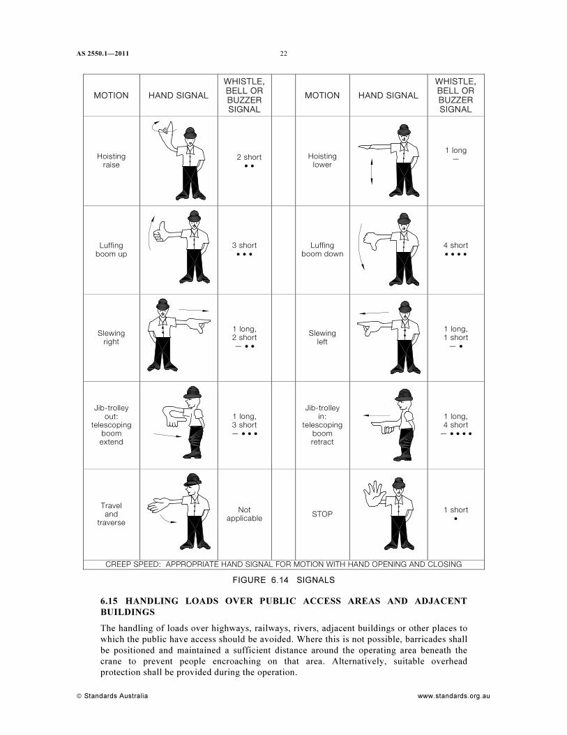
6.14.2 Hand signals
Hand signals should be as shown in Figure 6.14.

21 AS 2550.1—2011
www.standards.org.au © Standards Australia
6.14.3 Bell, buzzer and whistle signals
Bell, buzzer and whistle signals used should be as shown in Figure 6.14.
The bell or buzzer shall be located in a position where it can be readily heard by the crane
operator while at the control position.
If two or more cranes are operating in close proximity, the tones of each bell, buzzer or
whistle employed for the cranes shall be clearly distinguishable.
6.14.4 Radio communication
Where radio communication is used, the transmitting frequencies of the radio equipment
shall be selected to prevent interference to or from other radio equipment being used in the
vicinity of the crane.
Communicated instructions shall specify the motion first followed by the action.
AS 2550.1—2011
© Standards Australia www.standards.org.au
22
MOTION HAND SIGNAL
WHISTLE, BELL OR BUZZER SIGNAL
MOTION HAND SIGNAL
WHISTLE, BELL OR BUZZER SIGNAL
Hoisting raise
2 short • •
Hoisting lower
1 long —
Luffing boom up
3 short • • •
Luffing boom down
4 short • • • •
Slewing right
1 long, 2 short — • •
Slewing left
1 long, 1 short
— •
Jib-trolley out:
telescoping boom extend
1 long, 3 short — • • •
Jib-trolley in:
telescopingboom retract
1 long, 4 short
— • • • •
Travel and
traverse
Not applicable
STOP
1 short •
CREEP SPEED: APPROPRIATE HAND SIGNAL FOR MOTION WITH HAND OPENING AND CLOSING
FIGURE 6.14 SIGNALS
6.15 HANDLING LOADS OVER PUBLIC ACCESS AREAS AND ADJACENT
BUILDINGS
The handling of loads over highways, railways, rivers, adjacent buildings or other places to
which the public have access should be avoided. Where this is not possible, barricades shall
be positioned and maintained a sufficient distance around the operating area beneath the
crane to prevent people encroaching on that area. Alternatively, suitable overhead
protection shall be provided during the operation.
23 AS 2550.1—2011
www.standards.org.au © Standards Australia
6.16 NON-POSITIVE LIFTING ATTACHMENTS
Where loads are suspended by non-positive lifting attachments (e.g., magnetic, vacuum or
friction lifting attachments), personnel should be excluded from all areas that could be
affected by a falling load.
Where it is not possible to isolate personnel from the operation area of cranes fitted with
non-positive lifting devices, operational procedures shall be developed to prohibit personnel
working in the hazardous area; that is the area where personnel may be injured as a result of
failure of the lifting attachment.
The non-positive lifting device shall be sized to provide an adequate design factor on its
nominal rated capacity, taking into account the size, shape and mass of the lifted load.
6.17 INDICATING AND LIMITING DEVICES
Where indicating and limiting devices are provided, they shall not be switched off or made
dysfunctional during crane operation, except for—
(a) designed lifts in accordance with Clause 6.27; or
(b) testing and commissioning; or
(c) where the crane manufacturer has specified instructions for avoiding indicating and
limiting devices for specific operations.
6.18 RIDING ON THE CRANE STRUCTURE
Except for inspection, maintenance, commissioning, erection or dismantling purposes, only
those personnel correctly accommodated in the cabin or on the work platform shall be
permitted on the crane when it is operating. Personnel shall only ride on the crane structure
as necessary for inspection, maintenance, commissioning, erection or dismantling purposes.
A written procedure for riding on the crane structure shall be provided.
6.19 SUSPENSION OF PERSONS BY CRANE
6.19.1 General
A person shall only be suspended from a crane hook when accommodated in a workbox
designed for the purpose in accordance with AS 1418.17.
The use of the workbox shall be limited to those situations where it is necessary to elevate
personnel to carry out work where it is not reasonably practicable to use scaffolding or
equipment designed specifically to lift personnel.
6.19.2 Requirements for the crane used with a workbox
A crane used with a workbox shall—
(a) be fitted with a safety hook or moused accessory;
(b) be equipped with controls that return to the neutral position when released and this
action causes the motion to stop;
(c) be equipped with power lowering;
(d) be equipped with a positive free fall lockout control so that inadvertent
disengagement of the lockout is not possible;
(e) be fitted with an upper limit motion limiting device;
(f) be fitted with a down-limit motion limiting device, if the workbox is to be lowered
below the crane supporting surface;
(g) be such that at the maximum radius of the task to be performed, the crane has a
minimum rated capacity of 1000 kg; and
AS 2550.1—2011
© Standards Australia www.standards.org.au
24
(h) be such that, when the jib or boom of the crane is at its maximum radius for the task
to be performed, the rated capacity for the crane in this condition, when divided by 2,
is equal to or greater than the total load of the workbox and its contents.
6.19.3 Operation of the crane with suspended personnel
When personnel are suspended from a crane, the following requirements apply:
(a) The rated capacity of the workbox shall not be exceeded.
(b) The workbox and lifting attachments and records shall be inspected by a competent
person, prior to use.
(c) Personnel and materials shall be securely confined within the workbox.
(d) The workbox shall only be used to lift personnel and materials necessary to carry out
the work.
(e) The crane shall not be used to simultaneously raise, lower or suspend any other load.
(f) An appropriate work procedure shall be developed and implemented to transfer any
work materials from the workbox.
(g) The crane operator shall remain at the controls of the crane.
(h) All movements of the crane shall be carried out under power and free fall lockout
shall have been applied.
(i) Effective means of communication between any person in the workbox and the
operator shall be established.
(j) Mobile cranes shall not travel while people are in the workbox.
(k) Movements of the workbox shall be at slow speeds with minimum acceleration and
deceleration.
(l) The workbox shall not be secured to any structure except at designated landing(s).
NOTE: Workboxes should not be used in winds in excess of 7 m/s (25 km/h), electrical
storms, snow, ice, sleet or other adverse weather conditions that could affect the safety of
personnel.
(m) Flammable liquids, oxygen and acetylene cylinders, and similar flammable liquids,
shall be correctly secured and housed in a separate compartment from the personnel.
No more than the minimum quantities, sufficient to carry out the work, shall be
carried. Where flammable liquids are carried, a suitable fire extinguisher shall also be
carried.
(n) Personnel suspended from a crane shall wear a fall-arrest harness complying with
AS/NZS 1891.1, with the lanyard attached to a fall-arrest anchorage point.
(o) Personnel shall not enter or leave the workbox when elevated (except in an
emergency), unless each of the following conditions are met:
(i) A risk assessment has been completed that identifies that access and egress
from the workbox in this manner is safe, and that this means of access is safer
than all other alternative means.
(ii) The structural adequacy of the landing area has been established and the
landing area is clear.
(iii) Where the landing is at the edge of a structure, the maximum gap between the
workbox and landing does not exceed 100 mm, the workbox is secured to a
suitable point on the landing and access and egress does not take place unless a
fall-arrest harness is properly worn and attached to a suitable anchorage on the
structure.
25 AS 2550.1—2011
www.standards.org.au © Standards Australia
6.20 OPERATION NEAR AERIAL CONDUCTORS (OVERHEAD POWERLINES)
6.20.1 General
This Clause refers to hazards and risks presented by the set-up and operation of cranes in
the vicinity of overhead electrical conductors.
NOTES:
1 Various regulatory bodies in a number of States have issued codes of practice or industry
guidelines for the safe operation of cranes near overhead powerlines.
2 A conservative approach has been adopted. Separation distances have not been chosen based
purely on electrical voltages of conductors, nor whether the conductor is bare or insulated.
The distances were chosen based on experience and practical considerations, since cranes
cannot be operated as accurately as arcing distances can be calculated.
Before operating a crane from the stowed condition, a check for the presence of overhead
conductors and powerlines shall be undertaken.
Throughout this Clause, the following definitions apply:
(a) Aerial conductor—an overhead conductor that is either insulated or bare.
(b) Crane—includes crane, crane attachments (e.g., ropes and lifting beams) and the
crane load.
(c) Operation—where any crane components are moved or about to be moved from their
stowed position and in the instance of cranes having stabilizers, where stabilizers are
moved or about to be moved from their stowed position.
(d) Overhead powerline—aerial conductors and other parts that make up an aerial line for
the distribution and transmission of electrical energy.
(e) Electricity distributor—the power supply authority, transmission line operator,
generator, traction company or distribution company.
All aerial conductors shall be treated as ‘alive’ unless the crane operator has received from
the electricity distributor, or transmission line operator, documentary evidence that the
conductors have been positively de-energized, isolated and earthed.
Where such documentary evidence has been made available, it shall state the date and time
frame of isolation and any special conditions and precautions. The crane shall not be
operated in contravention of this documentary information.
6.20.2 Precautions when operating near live aerial conductors
The crane shall only be operated within close proximity of live aerial conductors if the
separation distances appropriate to the ‘no go zone’ or ‘spotter required zone’ and risk
controls given in Clause 6.20.3 are maintained.
A documented site-specific risk assessment shall be completed before the commencement
of the job by a trained and competent person. This assessment shall be verified immediately
before work commences, and its relevance monitored during the job. If initial associated
circumstances change, work shall cease until an appropriate risk assessment is undertaken.
Where a spotter is required to inform the operator in the event of the crane approaching the
zone boundaries shown, the following applies:
(a) The spotting operation shall be carried out by a competent person.
NOTE: Required competency levels may be defined by the Office of the Chief Electrical
Inspector or similar body in the applicable State.
(b) The spotter shall be positioned so as to minimize the risk of exposure to hazards.
(c) The spotter shall be able to clearly observe the separation distances.
(d) The spotter shall not undertake any other work whilst performing spotting duties.
AS 2550.1—2011
© Standards Australia www.standards.org.au
26
(e) The spotter shall be specifically instructed in the workplace hazards applicable to the
site.
(f) The spotter shall be able to communicate with the crane operator at all times during
erection, operation and dismantling.
6.20.3 Separation distances and risk controls
Where possible, the zone separation distances shall be not less than those shown in
Figure 6.20.3.
NOTE: The separation distances shown in Figure 6.20.3 include allowance for sag and sway of
line(s) due to the effects of wind and temperature.
Where the separation distances cannot be achieved, the electricity distributor shall be
notified in writing. The crane shall not be operated within the ‘no go zone’ until the
applicable requirements below are satisfied.
The separation distance between the crane and aerial conductor and risk controls when
operating in the vicinity of aerial conductors shall comply with the following:
(a) Overhead powerlines (up to and including 132 kV) The following applies:
(i) No go zone The crane shall not be operated in the ‘no go zone’ as indicated in
Figure 6.20.3 for overhead powerlines up to and including 132 kV, unless—
(A) written permission from the electricity distributor has been obtained;
(B) all conditions specified by the electricity distributor are complied with;
(C) the electricity distributor is notified before commencing work;
(D) a spotter performs spotting duties; and
(E) a pre-start site/job meeting has been convened and a risk assessment
completed.
(ii) Spotter required zone The crane shall not be operated in the ‘spotter required
zone’ as indicated in Figure 6.20.3 for overhead powerlines up to and including
132 kV, unless—
(A) written permission from the electricity distributor has been obtained;
(B) a spotter performs spotting duties; and
(C) a pre-start site/job meeting has been convened and a risk assessment
completed.
(b) Overhead powerlines (greater than 132 kV) The following applies:
(i) No go zone The crane shall not be operated in the ‘no go zone’ as indicated in
Figure 6.20.3 for overhead powerlines greater than 132 kV, unless—
(A) an easement entry permit has been provided by the electricity distributor;
(B) written permission from the electricity distributor has been obtained;
(C) all conditions specified by the electricity distributor are complied with;
(D) the electricity distributor is notified before commencing work;
(E) a spotter performs spotting duties; and
(F) a pre-start site/job meeting has been convened and a risk assessment
completed.
27 AS 2550.1—2011
www.standards.org.au © Standards Australia
(ii) Spotter required zone The crane shall not be operated in the ‘spotter required
zone’ as indicated in Figure 6.20.3 for overhead powerlines greater than
132 kV, unless—
(A) written permission from the electricity distributor has been obtained;
(B) an easement entry permit has been provided by the electricity distributor;
(C) a spotter performs spotting duties; and
(D) a pre-start site/job meeting has been convened and a risk assessment
completed.
(c) Public transport authorities Where aerial conductors are dedicated to the use of
public transport authorities (e.g., tramways and railways), the separation distance
shall be the same as that for aerial conductors up to and including 132 kV [see
Item (a)].
(d) Downshop conductors Before mobile machinery is set up for operation in the
vicinity of downshop conductors, the power supply to the conductors shall be isolated
prior to operation unless appropriate control measures have been developed and
implemented.
NOTES:
1 Downshop conductors (e.g., collector rails), should be clearly identified.
2 Clearances from downshop conductors should be in accordance with AS/NZS 3000.
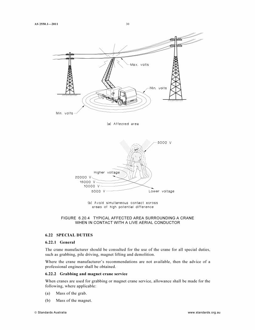
(e) Barriers at ground level Where people not involved in the lifting operation could
otherwise come into the area of possible voltage step potential, barriers shall be
provided at ground level to prevent this from occurring. Appropriate warning signs
shall be displayed on the barriers. Pedestrians should be barricaded from the area of
possible voltage step potential (see Figure 6.20.4) in the vicinity of the crane and
associated equipment.
(f) Person to crane contact Only the crane operator shall be in contact with any part of
the crane during operation. If the load needs to be steadied during lifting, a
non-conducting tag line shall be used. All persons involved in the crane operation in
contact with the ground shall be provided with appropriate means of insulation from
the ground.
NOTE: In many instances, more than one dogger may be required to handle tag lines located
to apply counter-reacting forces, to prevent the load swinging in the direction of tension of
one of the tag lines.
(g) Earthing systems An appropriate earthing system shall be fitted to the crane and
shall be in use. Operators and those working in proximity to the crane shall be
advised of the limits of the effectiveness of the earthing equipment.
NOTE: The purpose of the earthing system is to provide an alternate path to earth to minimize
risks to personnel and plant, and it may not be likely to trip circuit breakers that form part of
the electricity transmission system. For specific advice and guidance about the earthing of a
crane consult with the electricity distributor/provider.
(h) High visibility bunting Where high visibility bunting is applied to the conductors, it
shall not be regarded as insulation.

AS 2550.1—2011
© Standards Australia www.standards.org.au
28
DIMENSIONS IN METRES
FIGURE 6.20.3 CLEARANCES FROM LIVE AERIAL CONDUCTORS
29 AS 2550.1—2011
www.standards.org.au © Standards Australia
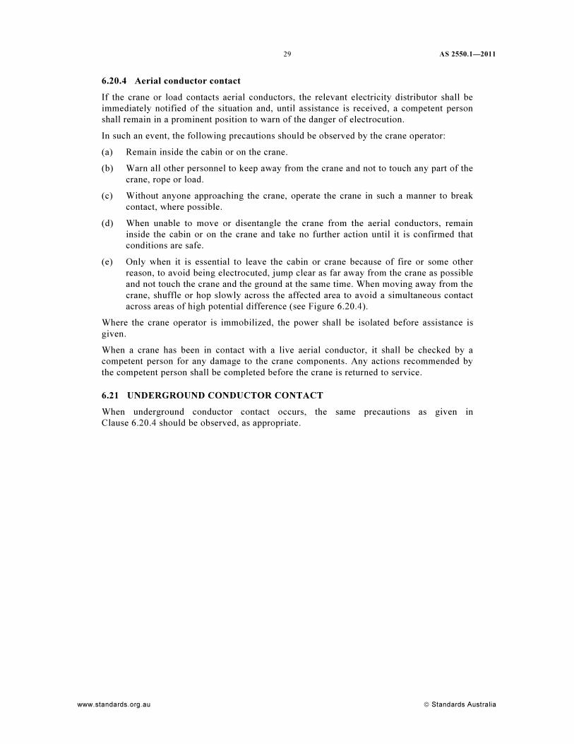
6.20.4 Aerial conductor contact
If the crane or load contacts aerial conductors, the relevant electricity distributor shall be
immediately notified of the situation and, until assistance is received, a competent person
shall remain in a prominent position to warn of the danger of electrocution.
In such an event, the following precautions should be observed by the crane operator:
(a) Remain inside the cabin or on the crane.
(b) Warn all other personnel to keep away from the crane and not to touch any part of the
crane, rope or load.
(c) Without anyone approaching the crane, operate the crane in such a manner to break
contact, where possible.
(d) When unable to move or disentangle the crane from the aerial conductors, remain
inside the cabin or on the crane and take no further action until it is confirmed that
conditions are safe.
(e) Only when it is essential to leave the cabin or crane because of fire or some other
reason, to avoid being electrocuted, jump clear as far away from the crane as possible
and not touch the crane and the ground at the same time. When moving away from the
crane, shuffle or hop slowly across the affected area to avoid a simultaneous contact
across areas of high potential difference (see Figure 6.20.4).
Where the crane operator is immobilized, the power shall be isolated before assistance is
given.
When a crane has been in contact with a live aerial conductor, it shall be checked by a
competent person for any damage to the crane components. Any actions recommended by
the competent person shall be completed before the crane is returned to service.
6.21 UNDERGROUND CONDUCTOR CONTACT
When underground conductor contact occurs, the same precautions as given in
Clause 6.20.4 should be observed, as appropriate.
AS 2550.1—2011
© Standards Australia www.standards.org.au
30
FIGURE 6.20.4 TYPICAL AFFECTED AREA SURROUNDING A CRANE
WHEN IN CONTACT WITH A LIVE AERIAL CONDUCTOR
6.22 SPECIAL DUTIES
6.22.1 General
The crane manufacturer should be consulted for the use of the crane for all special duties,
such as grabbing, pile driving, magnet lifting and demolition.
Where the crane manufacturer’s recommendations are not available, then the advice of a
professional engineer shall be obtained.
6.22.2 Grabbing and magnet crane service
When cranes are used for grabbing or magnet crane service, allowance shall be made for the
following, where applicable:
(a) Mass of the grab.
(b) Mass of the magnet.
31 AS 2550.1—2011
www.standards.org.au © Standards Australia
(c) Mass of other attachments.
(d) Mass of the load.
(e) Loads resulting from fast slewing.
(f) Grab or suction effects.
(g) Impact loads.
For these operations, consideration shall be given to the tear-off/break-out forces.
6.22.3 Lifting products of demolition
Lifting products of demolition may be hazardous because the loads may be greater than
assessed or may impose excessive dynamic loads on the crane. Cranes used for this purpose
shall have a rated capacity not less than 1.5 times the assessed load.
6.22.4 Inspection
After a crane has been used for special duties, it shall be subjected to an inspection, as
specified in Clause 7.4.3., before being returned to its usual lifting duties.
6.22.5 Recreational use
Crane structures shall not be used for recreational purposes.
6.23 WEATHER CONDITIONS
6.23.1 Wind conditions
Where it is necessary to lift loads with large wind-catching surfaces, the lift shall be
assessed taking full consideration of the wind loads likely to be experienced during the
operation and their effect on the load intended to be lifted. Such an assessment shall include
the likely effect a gusting or strong wind can have on the crane’s stability even when the
load being lifted is within its rated capacity.
An anemometer should be available at the working site, and located to provide an accurate
wind load reading on the crane or load.
Where wind speeds exceed the manufacturer’s operating recommendations, cranes shall be
placed out of service and, where applicable, storm brakes applied.
6.23.2 Visibility conditions
Where adverse weather conditions such as snow, fog and wind causing dust have an adverse
effect on visibility or the communication system, the crane shall be placed out-of-service
until conditions improve to such an extent that a dangerous situation no longer exists.
6.23.3 Wet conditions
Brake or clutch units and electrical equipment on all cranes shall be protected against the
ingress of water or other adverse weather conditions that may affect their efficiency.
Following shutdown periods and before the start of hoisting operations, all friction brakes
and clutches shall be carefully tested.
6.23.4 Lightning
Outdoor cranes should not be operated during a storm when lightning strikes could
reasonably be expected.
6.24 INCIDENT OR DAMAGE
When the crane is involved in any incident or the crane or equipment sustains failure or
damage that may affect its safe operation, it should be withdrawn from service.
AS 2550.1—2011
© Standards Australia www.standards.org.au
32
The crane operator shall report such occurrences.
NOTE: Statutory authorities may require such incidents to be reported.
The crane or equipment shall then be inspected and repaired as required by Section 7, and
declared satisfactory by a competent person before it is returned to service.
6.25 MODIFICATIONS TO CRANES
Modifications to any part of a crane, including the addition of signs, shall not be undertaken
without undergoing an engineering assessment by a competent person, for compliance with
AS 1418.1.
6.26 FIRE EXTINGUISHER
A fire extinguisher appropriate to the hazards involved shall be provided and correctly
fitted for every cabin-controlled crane.
6.27 DESIGNED LIFTS
Designed lifts shall comply with the requirements of this Standard and the applicable Part
of AS 1418. Designed lifts shall be preceded by a thorough, documented risk assessment
that will identify any hazards and the appropriate control methodologies.
Where multiple cranes are employed and their motions are not synchronized, the
requirements of Clause 6.28 shall apply.
NOTE: Guidance on designed lifts is given in Appendix D.
The rated capacity of a crane may be temporarily changed for the duration of a designed
lift. The crane marking need not be changed. The re-rating conditions shall be indicated in
writing to the operator.
The person developing the designed lift shall be a competent person, and shall define and
record the rationale for any deliberation associated with the review, as defined in this
Clause. A third party shall review the design characteristics of the crane. Consideration
shall be given to the effect this operation may have on the life of the crane.
A written work procedure shall be developed by the competent person, and shall include the
various control measures to be applied. The written work procedure shall be job specific
and shall specify the documents required for all items deemed necessary by the competent
person. The following items, as applicable, shall be included in the documentation:
(a) Crane identification.
(b) Crane configuration.
(c) Location of the site.
(d) Position of the crane(s) relative to the load and its final position.
(e) Climate and atmospheric conditions.
(f) Speed of crane movements (e.g., hoisting, slewing luffing, traversing).
(g) Load sharing in multiple crane lifts.
(h) Hoist speed matching in multiple hoist lifts.
(i) Synchronization of crane motions, or where this is not possible, methods taken to
reduce the effect of forces arising from the lack of synchronization.
NOTE: Lack of synchronization in crane movements (in particular travelling or slewing
motions) results in lateral forces being applied to the cranes, which may result in loss of
stability or structural damage. Procedures should be developed to monitor and control the
effect of lateral forces arising during such motions.
33 AS 2550.1—2011
www.standards.org.au © Standards Australia
(j) Crane support structure.
(k) Special lift operating procedure.
(l) Design checks, brake calculations, wheel loads, rope calculations, motor rating, load
and/or motion limits, hoist/block capacity.
(m) An inspection of all parts of the crane to be carried out in accordance with the
competent person’s instructions prior to and immediately after the completion of a
designed lift to verify the condition of the crane.
(n) Crane support considerations.
(o) Determination of centre of gravity.
A record of all designed lifts shall be maintained with the crane service record (logbook).
6.28 MULTIPLE HOIST OR CRANE OPERATION
6.28.1 General
Multiple crane lifting shall be used only when the physical dimensions, characteristics,
mass or required movement of the load prevent the operation from being carried out by a
single crane. Lifting operations using two or more cranes shall be preceded by a thorough,
documented risk assessment that will identify any hazards and the appropriate control
methodologies irrespective of whether the lift is a designed lift or is in accordance with the
requirements of this clause.
NOTE: During multiple crane operations, only motions in the same direction should be
undertaken simultaneously by the cranes, otherwise, the operation should be carried out in a
stepped sequence, undertaking only one motion at a time.
6.28.2 Crane type
Other than for designed lifts, lifting operations using two or more cranes shall use cranes of
the same type.
NOTE: For example, telescopic mobile crane/tower crane would require a designed lift
assessment.
6.28.3 Capacity requirements
Where the motions of multiple crane operations are not synchronized during the lifting
cycle, the following minimum capacity requirements for each crane shall apply:
(a) For two cranes ................................ 20% greater than the calculated share of the load.
(b) For three cranes .............................. 33% greater than the calculated share of the load.
(c) For four or more cranes .................. 50% greater than the calculated share of the load.
NOTE: These capacity requirements are not necessarily sufficient to address the hazards that may
arise during travel or slewing operations (see Clause 6.28.5.4).
6.28.4 Multiple hoist operation
Where a multiple crab crane is lifting a load other than that for which it was originally
designed, care shall be taken to ensure that the proportion of the load each crab supports is
accurately known.
Where a crane is fitted with two crabs and facility allowing tandem operation, the load shall
be handled in such a way that the rated load of each hoist is not exceeded and the load
being handled does not exceed the rated capacity of the crane.
AS 2550.1—2011
© Standards Australia www.standards.org.au
34
Where a crane is not fitted with facility for tandem operation or the load is suspended from
more than two hoist lines, load limiters shall be fitted to each hoist and the load shall be
handled in such a way that—
(a) the rated load for each line is not exceeded; and
(b) the load being handled does not exceed the rated capacity of the crane as specified in
Clause 6.28.3.
6.28.5 Planning for multiple crane hoisting
6.28.5.1 General
Multiple crane hoisting shall be planned with extreme care. Where multiple crane lifting is
involved, the following shall be considered and any resulting procedures shall be prepared:
(a) An accurate assessment of the proportion of the load to be carried by each crane.
(b) How the load proportioning is to be maintained.
(c) Whether each crane has appropriate additional capacity over the portion of the load to
be lifted.
(d) The operating characteristics of the cranes (e.g., speed of hoisting).
(e) Planning for keeping the hoist ropes within the range specified by the manufacturer.
6.28.5.2 Mass of load
If the load information is taken from a technical drawing, allowance should be made for
manufacturing tolerances. Loads should be checked for a build-up of deposits or contained
liquids that may increase the mass.
6.28.5.3 Mass of lifting gear
The mass of the lifting gear shall be part of the calculated load on the cranes and crabs and
its mass distribution shall be accurately known.
6.28.5.4 Load-handling attachments
Load-handling attachments shall be suitable for tandem operation. The use of non-positive
contact load-handling attachments, such as magnet and vacuum lifting appliances for
suspending a load between two or more cranes, shall be avoided. Loads shall not be
suspended at an angle.
6.28.5.5 Synchronization of the crane and crab motions
The crane motions should be synchronized; therefore, cranes of equal capacity and similar
operating characteristics should be used.
To allow for the probability of the motions of the cranes or crabs not being accurately
synchronized, particularly if the cranes or crabs have dissimilar operating characteristics,
the operation shall be performed at slow speeds with extreme care being exercised to
maintain the hoist ropes as close to vertical as possible. Procedures shall be developed to
monitor and control the effect of lateral forces arising during such motions.
NOTES:
1 The rated capacity of a crane is calculated on the assumption that the load will be raised and
lowered in a vertical plane. The crane structure will have been designed to withstand any
lateral loads imposed by accelerations in the various crane and crab motions; however, it is
unsafe to rely on this lateral strength to withstand horizontal components of non-vertical lifts.
2 In practice, there will always be some variation due to differences in response to the
activation of the motion controller and the setting and efficiency of the braking system.
35 AS 2550.1—2011
www.standards.org.au © Standards Australia
3 Synchronous operation of more than one crane and/or hoist may be carried out by a
combination of the following:
(a) Operator controls Two or more cranes may be operated by a common control station
such as a radio control system consisting of a master transmitter used to operate
separate receivers on each crane. The other transmitters are slaves that can only be
used when in single mode operation.
(i) Single mode is when each crane is operated by its own control station.
(ii) Tandem mode is when the crane combination is operated by a common control
station.
(b) Crane controls The control systems of the cranes being operated in tandem,
communicate with each other, such as by a bi-directional radio data link, to ensure the
following:
(i) All drives involved in the lifting motion are reliably switched off when an
overload or over-temperature limit of one of the hoist units is detected in the
system; however, the lowering motion is still possible for safety reasons.
(ii) All hoists involved in the lifting/lowering operation are switched off when a
lifting/lowering limit is actuated.
(iii) All travelling hoists involved in the operation are switched off when an
end-of-travel motion limit is actuated.
(iv) All cranes involved in the operation are switched off when an end-of-travel
motion limit is actuated.
(v) All associated axis drives are limited to the same rate in the event that a speed
reducing limit is actuated.
(vi) Any anti-collision systems between travelling hoist and/or cranes involved in a
tandem operation are bypassed.
6.28.5.6 Pick and carry
In pick and carry operations, the axis of both or all cranes or crabs shall be kept aligned in
the same direction. The possibility is that once out of alignment, the movement of one crane
or crab may push or pull either the other crane(s) or crab(s) and cause loss of stability.
NOTE: Instruments are available to monitor constantly the angle of the load, and the verticality
and force in each hoist rope throughout the lifting operation. Their use is recommended.
6.28.5.7 Wind
As multiple crane or crab hoisting operation is sensitive to weather conditions, particularly
wind speed. An adequate assessment of the prevailing conditions shall be made before
commencement of and during a multiple hoisting operation.
6.28.6 Supervision of a multiple crane hoisting operation
One competent person, who shall not be one of the crane operators, shall be in attendance
and in overall control of the multiple crane or crab hoisting operation. Only this person
shall give instructions to the crane operators, except in an emergency, when a stop signal
may be given by any person observing a situation leading to danger. If all necessary
locations cannot be observed from one position, additional competent personnel shall be
located at suitable positions to observe and report to the person in charge of the operation.
6.29 MANUALS
The manuals for operation, servicing, maintenance and recording of major and minor
occurrences to the crane or hoist and the operational environment shall be retained in a
location readily available to those who have a need to use them.
Where the crane service records (logbooks) or other records are retained on computer or
other electronic storage facility, the operators, maintenance and inspection personnel shall
be trained in the procedures to retrieve the required information.
NOTE: Requirements for the content of manuals are given in the applicable Part of AS 1418.
AS 2550.1—2011
© Standards Australia www.standards.org.au
36
6.30 VESSEL-MOUNTED CRANES
6.30.1 General
This Clause states the additional requirements for vessel-operated cranes for use in smooth
water except for Clause 6.30.10, which references requirements applicable outside smooth
water limits. The crane may be operated on a barge, pontoon or vessel. The combined mass
shall be considered as a vessel-mounted crane.
6.30.2 Mounting or operating position
The position of the crane on the barge, pontoon or vessel, both in the loaded and unloaded
conditions, shall take into consideration—
(a) the effect on freeboard;
(b) the strength of the vessel to support the crane structure;
(c) the installation of stops to prevent the crane approaching the vessels side; and
(d) the method of securing the crane when working outside smooth water limits.
6.30.3 Vessel characteristics
The list and freeboard allowable with the rated capacity and test load conditions shall be
determined by a competent person experienced in crane design and stability of waterborne
vessels.
NOTES:
1 As a general guide, the maximum list of the vessel under rated capacity conditions should not
exceed ±5 degrees with one half of the freeboard remaining. Confirmation should be obtained
from the crane manufacturer on the de-rating of the crane from land-based ratings when on
the barge, pontoon or vessel.
2 The manufacturer’s rated capacities for cranes mounted on vessels are frequently not greater
than 70% of the land-based rated capacity.
6.30.4 Items to be verified
A design check shall include the verification of the following details:
(a) Allowable freeboard of the vessel.
(b) Crane manufacturer’s rated capacity when operating on a barge, pontoon or vessel
combination giving consideration to Clause 6.30.3.
(c) Loads in the structure when the barge or pontoon is at maximum heel or list.
(d) Amount and position of ballast.
(e) Depth of water below the vessel, to ensure the vessel does not ground.
(f) Limiting weather conditions for the crane vessel combination.
(g) Ties, anchorages and supports are adequate at minimum and maximum heel or list.
6.30.5 Grabbing cranes
Prior to performing grabbing operations, a hazard identification and risk assessment shall
be completed by a competent person.
Where grabbing cranes are operated on a barge or pontoon, the mass of the grab and
contents should not exceed 75% of the rated capacity and a further 25% reduction of the
rated capacity of vessel-mounted cranes should be made where suction effects are present.
6.30.6 Pile removal operations
Prior to performing pile removal operations, a hazard identification and risk assessment
shall be completed by a competent person.
37 AS 2550.1—2011
www.standards.org.au © Standards Australia
Where a vessel-mounted crane is engaged in removal of piles and buried posts,
consideration shall be given to the buried depth and the angle of repose of the binding
material.
6.30.7 Testing
6.30.7.1 General
The crane and vessel combination shall be inspected after erection and before application of
any loads to ensure all ties, anchorages and ballast are in place and correctly secured and
the crane configuration is in accordance with the crane manufacturer’s or a competent
person’s advice and free from any defects that would preclude the vessel-mounted crane
from safely handling the test load.
A pre-operation test with no load applied shall be carried out to ensure the correct operation
of all controls, cut-outs, contactors, brakes, limiters and other devices as fitted.
The rated capacity indicator and all limits shall be checked to ensure the reduced rated
capacity and any increase in radius due to list of the vessel combination is considered and
appropriate action taken.
6.30.7.2 Stability test
If it is not possible to anchor the vessel to the shore, the vessel should be anchored to a craft
alongside. The anchorage should be of sufficient length to allow the vessel to take up a
natural list in the water.
The crane should be checked without load through 360 degrees of slew with the boom in the
least stable position to establish the position of maximum loss of freeboard of the vessel.
The position of minimum freeboard of the vessel shall be placed adjacent to the anchorage.
The crane shall be slewed through 360 degrees to ensure there is adequate freeboard and the
vessel will not be swamped under adverse conditions.
The crane shall be placed at the position of least stability and the test load applied
incrementally, checking the freeboard at each increment.
6.30.7.3 Function test
After the stability test, the crane shall be function tested. The function test should be
conducted with all motions operated at the lowest speeds.
The boom shall be set at maximum radius and the rated capacity applied. The crane shall
then be operated through all motions and the load hoisted to ensure that the load is applied
in the full range of each motion.
6.30.7.4 Brake test
The load shall be increased to 110% of the crane line pull and shall be hoisted 3 m above
the ground then lowered and arrested just clear of the ground. Where applicable, the hoist
and luffing brakes shall be tested and proved capable of sustaining the 110% test load for
10 min. This test may be carried out following the performance tests at operating
temperatures. Unless indicated by the manufacturer, the test shall be carried out on the top
layer of the drum.
6.30.8 Post-test assessment
After stability and function tests have been completed, a competent person shall complete a
thorough assessment to ensure the vessel and crane combination has withstood the test
loadings without structural damage and the mechanisms function free of any defect that will
affect the safety of the crane.
All cut-outs and limits shall be reset to normal operation requirements.
AS 2550.1—2011
© Standards Australia www.standards.org.au
38
6.30.9 Rated capacity charts
The rated capacity charts of the crane shall be securely fastened and clearly endorsed with
de-rating requirements applicable to the installation of the crane on the vessel.
6.30.10 Offshore and ship-mounted cranes
The requirements for shipping and operation outside smooth water are in various
classification societies’ rules.
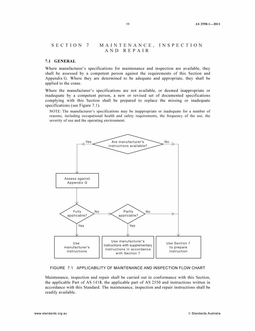
39 AS 2550.1—2011
www.standards.org.au © Standards Australia
S E C T I O N 7 M A I N T E N A N C E , I N S P E C T I O N
A N D R E P A I R
7.1 GENERAL
Where manufacturer’s specifications for maintenance and inspection are available, they
shall be assessed by a competent person against the requirements of this Section and
Appendix G. Where they are determined to be adequate and appropriate, they shall be
applied to the crane.
Where the manufacturer’s specifications are not available, or deemed inappropriate or
inadequate by a competent person, a new or revised set of documented specifications
complying with this Section shall be prepared to replace the missing or inadequate
specifications (see Figure 7.1).
NOTE: The manufacturer’s specifications may be inappropriate or inadequate for a number of
reasons, including occupational health and safety requirements, the frequency of the use, the
severity of use and the operating environment.
Yes
Yes Yes
No
No
Use manufacturer’s
instructions
Use manufacturer’sinstructions with supplementaryinstructions in accordance
with Section 7
Assess againstAppendix G
Use Section 7to prepareinstruction
No
Are manufacturer’sinstructions avai lable?
Fullyapplicable?
Partlyapplicable?
FIGURE 7.1 APPLICABILITY OF MAINTENANCE AND INSPECTION FLOW CHART
Maintenance, inspection and repair shall be carried out in conformance with this Section,
the applicable Part of AS 1418, the applicable part of AS 2550 and instructions written in
accordance with this Standard. The maintenance, inspection and repair instructions shall be
readily available.

AS 2550.1—2011
© Standards Australia www.standards.org.au
40
The instructions shall be written in plain English and shall give specifications for suitable
tools and consumable items such as ropes, lubrication and hydraulic fluids.
All inspections, maintenance and repairs shall be carried out by a competent person.
NOTE: Guidance on safe work procedures is given in Appendix E.
7.2 MAINTENANCE
A preventative maintenance program shall be established giving consideration to the
manufacturer’s recommendations. It shall be based on the working environment and the
frequency and severity of use of the crane.
NOTE: Recommended servicing frequencies for different crane classifications are given in
Appendix F.
When parts and components are replaced, replacements shall be identical or equivalent to
the original equipment parts and components.
Where past experience has shown particular problems with a crane, a specific rectification
program shall be instigated.
All safety-related malfunctions and problems shall be corrected before the crane is returned
to service.
7.3 INSPECTION
7.3.1 General
Inspections shall be carried out at sufficient frequency to ensure the crane is kept in a safe
and satisfactory condition. Inspections shall be carried out in conformance with this
Standard, the appropriate part of AS 2550 and instructions written in accordance with this
Standard. All such work shall be noted in the records. Inspection shall be as follows:
(a) Pre-operational inspection.
(b) Routine inspection.
(c) Periodic third-party inspections.
(d) Major inspection.
For lifting devices, the inspection requirements of AS 4991 shall apply.
7.3.2 Pre-operation inspection
Before the commencement of each work shift, the crane shall be given a visual inspection
and functional test. The visual and functional tests may be carried out by the operator with
the intention of identifying obvious damage. The inspection and test should include the
following:
(a) Operating and emergency controls.
(b) Brakes.
(c) Safety switches and interlocks.
(d) Structure.
(e) Wire ropes to ensure they are on the drum and correctly reeved on the sheave.
Any personal protective equipment should also be inspected for correct function.
Identified safety-related problems shall be rectified and recorded prior to using a crane.
41 AS 2550.1—2011
www.standards.org.au © Standards Australia
7.3.3 Routine inspection
Routine inspection shall be carried out in accordance with the manufacturer’s
recommendations.
NOTE: The inspection should include all items specified in instructions written in accordance
with this Standard for routine inspections, including the following:
(a) All functions and their controls for speed, smoothness of operation and limits of motion.
(b) All emergency and safety switches and interlocks.
(c) Lubrication of all moving parts, inspection of filter element/s and fluid levels.
(d) Visual inspection and measurements, as necessary, of structural members and other critical
components such as brakes, gears, fasteners, pins, shafts, wire ropes, sheaves, locking
devices, electrical contactors, wear on wheels and rails.
(e) Signage, including warning signs and control markings.
(f) Checking electrical, mechanical and structural components for safe condition and function.
(g) Additional items nominated in the instructions written in accordance with this Standard.
Particular attention should be paid to any component with a recent or existing history of
repeated failures.
Opening of cover plates and removal of guards shall be as considered necessary by the
inspector due to the existing condition.
When parts and components are replaced, the replacements shall be identical or equivalent
to the original parts or components.
A written report shall be furnished on completion of the inspection.
NOTES:
1 A competent person may recommend that routine inspections be carried out more frequently.
2 Where manufacturer’s recommendations are not available, the routine inspections should take
place at intervals not exceeding those shown in Table F1 of Appendix F, unless the crane is
not in service.
7.3.4 Periodic third-party inspections
Each crane shall undergo a periodic third-party inspection to provide independent advice on
whether the level of maintenance and repairs are in accordance with this Standard.
The frequency of periodic third-party inspection shall be based on the working environment
and the frequency and severity of use of the crane.
NOTE: The periods specified in Table F1 of Appendix F should not be exceeded.
The inspection shall include all items specified in instructions written in accordance with
this Standard and include all items specified by the manufacturer for annual inspection
together with all routine inspection and maintenance items (see Clause 7.3.3).
As part of this inspection, the maintenance records of the crane shall be reviewed prior to
the inspection. After the inspection, a report on the current condition of the crane shall be
compiled.
NOTE: The usage of the crane should be verified for consistency with the design classification.
Particular attention should be given to the following:
(a) Past state of loading and utilization as compared to the crane classifications.
(b) Future intended state of loading and utilization as required by the user of the crane.
The inspection shall include checking electrical, mechanical and structural components for
safe condition and function. Opening of cover plates and removal of guards shall be as
considered necessary by the inspector due to the existing condition. Particular attention
shall be paid to any component with a recent or existing history of repeated failures.
AS 2550.1—2011
© Standards Australia www.standards.org.au
42
The inspection shall ensure that the requirements of Clauses 7.3.2, 7.3.3 and 7.3.5 have
been completed.
NOTES:
1 As the result of a periodic third-party inspection, a competent person may recommend a major
inspection.
2 For details of inspections for particular types of cranes, refer to relevant Part of the AS 2550
series.
3 Table F1 of Appendix F provides guidance on the inspection frequency for periodic third-
party inspections for typical crane classifications where a program of third-party inspections
is instituted.
7.3.5 Major inspection
Cranes shall be subjected to a major inspection to assess their suitability for continued safe
operation as follows:
(a) Unless assessed in accordance with Section 9 to determine when a major inspection is
due, after two-thirds of the design life specified by the manufacturer or the original
design Standard or, where this is unknown after 7 years of use.
(b) When an old crane is to be recommissioned and previous operating records do not
exist or the Standard to which it was designed and built is unknown.
The major inspection shall involve examination of those critical components identified by
the manufacturer, competent person or the assessment conducted in accordance with
Section 9. Where necessary, the crane shall be stripped down and paint, grease and
corrosion removed from critical components to allow a complete and thorough inspection.
Particular attention shall be given to the following:
(i) Structural, mechanical, electrical, instrumentation, control and operational anomalies.
(ii) Non-destructive testing of all nominated critical areas for evidence of cracking due to
fatigue or excessive stress.
(iii) Components whose maintenance records indicate repeated failures.
(iv) Braking systems.
(v) Adequacy of safety instructions and manuals for operation and maintenance.
(vi) Manufacturer’s safety upgrades.
A written report shall be furnished on completion of the inspection. A competent person
shall assess the results with regard to risks and hazards associated with the crane’s current
operation.
The following apply:
(A) The competent person shall specify the maintenance necessary to ensure its continued
safe operation.
(B) The competent person shall identify components that require particular attention in
subsequent periodic inspections.
43 AS 2550.1—2011
www.standards.org.au © Standards Australia
(C) The competent person shall determine the reasonable practicability of applying the
current requirements of the AS 1418 series, in particular the following:
(1) Rated capacity limiter and/or indicator.
(2) The indicating and motion limiting devices.
(3) Emergency retrieval system.
(4) Platform, handrails and gate.
(5) Controls and emergency stop (e.g., ability to unintentionally engage free fall).
Cranes assessed to be unsafe shall not be returned to service until rectified and reassessed
as safe to return to service.
NOTE: Persons carrying out such inspections should be supervised by a professional engineer.
7.4 REPAIRS
7.4.1 General
Any part of a crane that becomes so worn or damaged as to constitute a hazard or impairs
the operation of the crane, or may constitute a hazard before the next routine inspection,
shall be repaired or replaced.
NOTE: The repaired or new parts should comply with the manufacturer’s recommendations and
specifications, or the recommendations of a competent person, taking due cognizance of the
Standard to which it was designed.
All repairs shall be carried out by competent persons under competent direction and
supervision. The repairs shall be appropriately tested.
All repairs shall be adequately documented and recorded in accordance with Clause 7.5.
7.4.2 Assessment for repair procedure
A competent person shall make an assessment of the defects and damage requiring repair.
NOTE: The assessment should be recorded and form a report. The report should contain the
following:
(a) Details of how the incident happened or circumstances leading to the discovery of the
defective parts.
(b) Nature and extent of the damage and defects.
(c) Proposed action based on the manufacturer’s recommendations.
7.4.3 Alternative recommendations
7.4.3.1 Competent person’s report
Where it is not possible to obtain the manufacturer’s recommendations, or it is decided not
to follow the manufacturer’s recommendations, a competent person shall consider and
report on the following, as appropriate:
(a) Details of the proposed repair.
(b) Repair procedures.
(c) Design analysis.
(d) Selection of replacement material.
(e) Welding procedure specifications.
(f) Details of any heating or straightening process.
(g) Selection of the most appropriate method of non-destructive examination, including
the extent and level of testing.
(h) Post-weld heat treatment procedure.

AS 2550.1—2011
© Standards Australia www.standards.org.au
44
(i) Compliance with working and detailed drawings.
(j) Final acceptance and testing procedure.
7.4.3.2 Management of repairs
Following the review of the competent person’s report, the equipment shall be repaired or
scrapped. Where any component is scrapped, arrangements should be made to dispose of
the damaged component in a manner that ensures it remains unusable as a load-carrying
component.
Where it is decided to implement the manufacturer’s recommendations, instructions
incorporating such recommendations shall be prepared. Such instructions shall be followed.
Where it is decided not to implement the manufacturer’s recommendations, then the
competent person’s recommendations shall be followed.
A records management system, which ensures all activities affecting the repair are fully
documented, shall be maintained. These records shall be transferred with the ownership of
the crane and retained for the life of the crane.
As a minimum, the following records shall be retained:
(a) Detailed drawings and calculations.
(b) Material test certificates.
(c) Non-destructive examination reports.
(d) Inspection and testing procedure and details.
(e) Welding procedure records.
(f) Welder qualification records.
(g) Heat treatment charts.
(h) Dimensional checks.
(i) Inspection reports.
(j) Final acceptance testing.
(k) Certificate of compliance.
(l) Competent person’s report.
(m) The competent person’s qualifications.
(n) Repairer’s report.
Following repairs, the crane shall undergo the load and operational tests specified in the
applicable Part of AS 1418 to an extent commensurate with the type of alteration or repair.
7.4.4 Repair work
The repairer selected to carry out the work shall be acceptable to the competent person.
Repair work shall be carried out according to the following:
(a) Personnel with the necessary qualifications and experience shall be engaged on the
work.
(b) Work instructions shall be provided.
(c) All work shall be conducted in accordance with relevant Australian Standards or
other applicable national or international Standards.
(d) All final non-destructive testing shall be conducted by a competent person.
A records management system shall be established for the documentation produced by
repairers and received from other bodies for transfer to the owner.
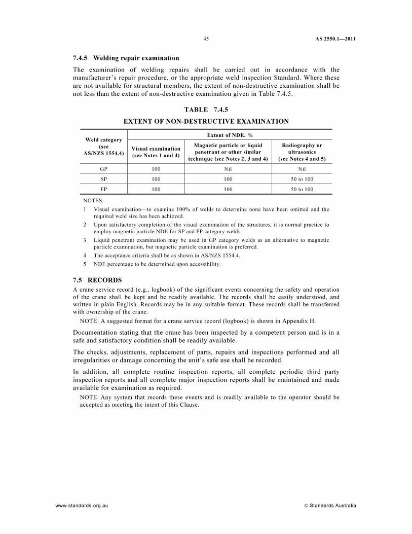
45 AS 2550.1—2011
www.standards.org.au © Standards Australia
7.4.5 Welding repair examination
The examination of welding repairs shall be carried out in accordance with the
manufacturer’s repair procedure, or the appropriate weld inspection Standard. Where these
are not available for structural members, the extent of non-destructive examination shall be
not less than the extent of non-destructive examination given in Table 7.4.5.
TABLE 7.4.5
EXTENT OF NON-DESTRUCTIVE EXAMINATION
Extent of NDE, %
Weld category
(see
AS/NZS 1554.4)
Visual examination
(see Notes 1 and 4)
Magnetic particle or liquid
penetrant or other similar
technique (see Notes 2, 3 and 4)
Radiography or
ultrasonics
(see Notes 4 and 5)
GP 100 Nil Nil
SP 100 100 50 to 100
FP 100 100 50 to 100
NOTES: 1 Visual examination—to examine 100% of welds to determine none have been omitted and the
required weld size has been achieved.
2 Upon satisfactory completion of the visual examination of the structures, it is normal practice to
employ magnetic particle NDE for SP and FP category welds.
3 Liquid penetrant examination may be used in GP category welds as an alternative to magnetic
particle examination, but magnetic particle examination is preferred.
4 The acceptance criteria shall be as shown in AS/NZS 1554.4.
5 NDE percentage to be determined upon accessibility.
7.5 RECORDS
A crane service record (e.g., logbook) of the significant events concerning the safety and operation
of the crane shall be kept and be readily available. The records shall be easily understood, and
written in plain English. Records may be in any suitable format. These records shall be transferred
with ownership of the crane.
NOTE: A suggested format for a crane service record (logbook) is shown in Appendix H.
Documentation stating that the crane has been inspected by a competent person and is in a
safe and satisfactory condition shall be readily available.
The checks, adjustments, replacement of parts, repairs and inspections performed and all
irregularities or damage concerning the unit’s safe use shall be recorded.
In addition, all complete routine inspection reports, all complete periodic third party
inspection reports and all complete major inspection reports shall be maintained and made
available for examination as required.
NOTE: Any system that records these events and is readily available to the operator should be
accepted as meeting the intent of this Clause.
AS 2550.1—2011
© Standards Australia www.standards.org.au
46
S E C T I O N 8 I N S P E C T I O N O F R O P E S , H O O K S
A N D L I F T I N G G E A R
8.1 ROPES
8.1.1 Replacement of ropes
The examination and discard criteria for wire ropes and their replacement shall be in
conformance with the crane manufacturer’s guidelines or, where not available, AS 2759 and
AS 1418.1. For multiple rope hoists, the ropes shall be matching ropes of the same
construction and tensile strength.
8.1.2 Rope reeving
Where it is possible to vary the number of falls of the hoist rope or parts of rope in the
luffing system, these shall be in accordance with instructions written in accordance with
this Standard for boom and jib lengths and loads to be lifted.
NOTES:
1 If a load moment system is fitted, the system generally operates accurately only when its
setting corresponds to the length of boom or jib fitted and the type of rope reeving adopted.
2 Where a crane is fitted with a load-sensing device, the device may require adjustment after a
change of reeving before the crane is placed in service.
8.1.3 Rope guards or keepers
Where rope guards or keepers are fitted to sheaves, hook blocks or drums, they shall remain
in their correct positions and shall be removed only for the purposes of maintenance,
inspection or adjustment.
NOTE: This is of particular importance if, under certain circumstances, the rope system develops
a slack rope condition. Failure to observe this could allow a rope to run off a sheave or drum and
become trapped or damaged.
8.1.4 Guide rollers and guide sheaves
Where guide rollers or guide sheaves are fitted, they shall be checked frequently to ensure
that they are free to rotate. Where boom or jib protective strips are fitted, they shall be
frequently checked for security and serviceability.
NOTE: A seized roller or sheave may cause serious damage to a rope, leading to its premature
failure.
8.1.5 Rope drums and sheaves
Rope drums and sheaves shall be examined for wear, at regular intervals.
Sheaves shall revolve true and freely on their supporting shafts and particular attention
shall be given to lubrication.
8.1.6 Rope terminal fittings
Wire rope terminations shall be carried out in accordance with manufacturer’s
specifications. In the absence of manufacturer specifications, terminal fittings as specified
in AS 2759 shall be used to attach a rope to a drum, anchorage, hook block or structure of
the crane. Improvised fittings shall not be used.
Attention shall be given to the assembly of wedge and socket fittings, and such fittings shall
be provided with a rope tail clip as specified in AS 2076.
47 AS 2550.1—2011
www.standards.org.au © Standards Australia
8.1.7 Rope lengths
Ropes of the correct length shall be fitted. Before hoisting operations commence following
installation of a new rope or a change of configuration, the rope drums shall be checked in
the extreme spooling conditions to ensure that the rope lengths are correct. The settings of
the limit devices shall be checked.
NOTE: With variable boom or jib lengths it may be necessary to fit a specific length of rope for a
particular boom or jib length and rope reeving combination. Too short a rope may result in the
rope completely paying out with the entire load being taken by the anchorage. Too long a rope
may exceed the drum spooling capacity and result in the rope riding over the flanges and
becoming trapped in the machinery causing severe damage and possibly premature rope failure.
8.1.8 Rope stretch
Rope stretch may create problems with the setting of hoisting limiting devices and the
overfilling of the drum. Frequent inspections, particularly during the early life of the
installed rope, shall be carried out to determine whether the limiting devices require
adjustment or the rope needs to be cut back to the appropriate length.
8.1.9 Examination of ropes
A visual examination shall be performed during the pre-operational inspection for kinking,
bird-caging, damage and correct reeving.
A thorough examination shall be carried out by a competent person during the routine
inspection phase. The acceptance and discard criteria shall be in accordance with AS 2759.
NOTE: Rope wear is affected by climatic and environmental conditions, e.g., saline, corrosive or
abrasive atmosphere.
Particular attention should be paid to those sections of rope close to rigid terminal fittings.
NOTE: Ropes that are composed or more than one layer of strands, such as non-rotating ropes,
may deteriorate internally at the interface between the layers.
If multi-layer drums are used, the examinations hall include not only that part of the rope
that is in constant use, but also that part of the rope that remains spooled and inoperative on
the drum for long periods.
Boom and fly-jib suspension ropes are often placed at positions remote from the basic crane
structure. Such ropes shall be carefully examined, particularly those sections lying round
sheaves.
8.2 HOOKS AND HOOK BLOCKS
The hook or hook block shall be capable of handling the nominated load. The hook shall not
be loaded beyond its working load limit.
To prevent displacement of the sling or load, the hook should be provided with a safety
catch or other effective device to minimize the risk of the sling or load becoming detached.
The hook shall not be overcrowded.
NOTE: Where multiple slings are used, they should be attached to a bow-shackle, which is then
placed on the hook. This prevents the danger of the hook being strained owing to the spread of
the slings and also the danger of a sling fouling the safety catch or slipping over the point of the
hook.
All end links, rings or shackles shall ride freely on the hook.
NOTE: When the crane is working with a single fall of rope and the load is set down, thus
relieving the tension in the hoist rope, the hook can spin. Personnel should always exercise care
when approaching the hook to disconnect the sling.
AS 2550.1—2011
© Standards Australia www.standards.org.au
48
8.3 LIFTING GEAR
8.3.1 Identification and marking
Each lifting attachment shall be clearly and permanently marked in accordance with
AS 4991.
8.3.2 Inspection
All lifting attachments shall be inspected immediately prior to use. Regular inspection,
consistent with the design and usage of the attachments, shall be carried out by a competent
person, and the extent of each inspection shall be consistent with the design and usage of
the attachment.
NOTE: See Clause 7.41 for more information.
49 AS 2550.1—2011
www.standards.org.au © Standards Australia
S E C T I O N 9 M A J O R A S S E S S M E N T F O R
C O N T I N U E D U S E O R C H A N G E D O P E R A T I O N
9.1 GENERAL
Cranes are designed for a finite lifetime duty, which is given in load cycles and loading
intensity and is not principally related to calendar working time. Classification of crane
duty provides the crane owner a means to specify the intended duty in order to achieve the
intended useful operational lifetime of the crane.
Typically, the operational lifetime for industrial cranes is 25 years; however, a specified
crane classification may be related to any calendar time depending on the application (e.g.,
5–10 years for a special limited use or 40 years for a long-term investment).
Approaching the design duty means an increased probability of hazards, which are unlikely
to be uncovered by periodic, physical inspections. For the safety of the crane operation, it is
crucial that the actual duty is monitored regularly and compared to the design duty.
This Section specifies a method to monitor, during a long-term operation, the actual duty
and how to compare this to the original design duty, which was specified through the
classification (i.e., C, M and S ratings).
The design working period (DWP) introduced in this Standard is directly related to a
theoretical design life and it shall not be considered as a guaranteed life in any respect. Due
to the probabilistic nature of metal fatigue and other influencing factors, premature failures
during the design life cannot be ruled out; however, the design working period represents a
proven estimate of a safe operational life of the crane, with due consideration to specified
design regulations and acceptable design factors.
The design working period is measured in hours or cycles. It is based on the crane being
maintained in correct working order.
9.2 RECORDING OF CRANE OPERATION
9.2.1 General
The crane user should keep records of the crane usage, adequate to identify the criteria
specified by the crane manufacturer and applicable to carry out the assessments described in
this Standard.
Records shall be kept of maintenance, inspections, repairs, modifications and relevant
exceptional occurrences (e.g., overloads, extreme climatic conditions and collisions).
NOTE: Failure to keep records of use will dictate the necessity for more frequent major
inspections (see Table 9.6.2).
9.2.2 Methods of duty recording
Estimation of the duty history may be divided into the following categories, based on
systematic and reliable data collection and documentation procedures:
(a) Crane operation data is recorded by a special, purpose-built system, which always
operates automatically when the crane is in use. The crane driver does not have a
possibility to switch off the recording system.
(b) The crane is provided with counters recording the crane operation data. The user
collects and documents the operation data manually from the counters.
(c) The crane duty history is estimated and recorded during the periodic third-party
inspection and is based on a regular process in which the crane is working. The crane
is an integral part of the process. Process data is documented.
AS 2550.1—2011
© Standards Australia www.standards.org.au
50
(d) The crane duty history is estimated and recorded, based on a general production data
of the site, where the crane is working.
(e) The crane duty history is unknown (e.g., in case of a second-hand crane). The duty
for DWP calculation is based on rational estimate or assumed to be according to
design classification and design life reduced, using the factor f1 from Table 9.6.2
(i.e., 1.5).
NOTE: Design life is generally 25 years for the structure and 10 years for mechanisms, unless
specified.
9.3 ASSESSMENT OF DESIGN WORKING PERIOD
9.3.1 General
Many components of a crane may fail because of metal fatigue, which is difficult to predict
or estimate by physical inspections. Safeguarding against fatigue failure by physical
inspections only is uneconomical due to the following:
(a) The safe time window for an inspection from detectable to critical crack size may be
short, leading to unnecessary frequent inspections.
(b) Detecting of a fatigue crack may be impractical, often requiring major disassembly of
a component.
(c) Planning and scheduling of future repairs of the crane is not possible.
A ‘non-acceptance’ by an inspection requires typically immediate actions and
possibly interruption of crane operation.
The purpose of the assessment of DWP is to estimate accumulated duty of the crane and
assess its remaining life.
It is assumed that all inspections scheduled for the crane have been carried out, that any
damages suffered during the operation are appropriately repaired and that maintenance
work and replacement of worn parts are carried out in accordance with the manufacturer’s
instructions or, where not available, the instructions of a competent person.
9.3.2 Schedule
Assessments of DWP should be carried out in conjunction with the periodic third-party
inspections.
A competent person shall conduct the assessment, unless the crane is equipped with an
automatic recording system [see Clause 9.2.2(a)].
9.3.3 DWP calculation method
The applied DWP calculation method should follow the specification and classification of
the original design Standard, as closely as possible. Clause 9.6 gives DWP calculation
methods for cranes classified and designed according to AS 1418.1.
The DWP calculation shall cover the crane as a whole including the structure and
mechanism.
The classification or design basis in the previous Standards may not be in accordance with
the current applicable Part of AS 1418. In order to have a solid theoretical basis for the
DWP calculation, the owner may ask the manufacturer or a competent person for a
re-classification according to the current Standard. The modified design classification shall
correspond to an equivalent or lower duty than the original one.
51 AS 2550.1—2011
www.standards.org.au © Standards Australia
9.4 MAJOR ASSESSMENT
9.4.1 General
The major assessment shall contain both—
(a) a theoretical part, where the remaining design life of each component of the crane is
analysed based on the duty estimation; and
(b) a practical part, where physical inspections of all critical components and systems of
the crane are inspected for integrity and functionality.
Upon checking the remaining life of the critical components, the competent person shall
identify components that have reached their design life that require overhaul for future safe
use.
NOTE: It should be recognized that the different parts of the crane approach the design limits at
different phases, depending on the type of the use and configuration of the crane. These
differences should be considered in the major assessment.
The theoretical analysis of the component remaining design life does not have to rely on the
methods of the original design Standard, but state of the art methods may be applied instead. This
should include consideration of the measured work cycles and their true effect on the crane
fatigue.
The major assessment shall be carried out under the supervision of a competent person. The
procedure should be based on the information provided by the crane manufacturer or, where
unavailable, the competent person shall determine the scope of the inspection.
9.4.2 Criteria for major assessment
A major assessment shall be made to survey the condition of the crane, when the
assessment of DWP indicates that the crane duty will reach one of the design limits prior to
the next periodic third-party inspection, or one of the following indicates it should be done
earlier:
(a) Any increase in the frequency of the reported defects.
(b) When an inspection reveals a significant deterioration in the condition of the crane.
In cases where the user takes into operation a second-hand crane, for which there is no
information concerning the earlier operation, the major assessment shall be made prior to
using the crane.
9.4.3 Manufacturer’s instructions
The manufacturer shall provide the user with the classification data necessary for the DWP
assessment. This information shall be given in the owner’s manual of the crane.
Additionally, the manufacturer shall specify the following:
(a) Limits for exceptional conditions and loadings to which the crane is designed.
(b) List of components and areas to be included in the major assessment.
(c) Methods and acceptance criteria for physical inspections.
(d) Recommendations for overhaul requirements in respect to findings in major
assessment.
(e) Criteria for findings preventing the further use of the crane.
NOTE: In the absence of manufacturer’s instruction, see Clause 7.1.
9.4.4 Report
A report of the major assessment shall be prepared. The report shall be kept with other
service documents of the crane.
AS 2550.1—2011
© Standards Australia www.standards.org.au
52
As a minimum, the report shall contain the following:
(a) Identification of the criteria used for the assessment.
(b) The results and significant findings.
(c) Requirements for any action to be completed before further use of the crane.
(d) Recommendations for actions to be carried out within a given operational time.
(e) New DWP prior to the next major assessment.
(f) Modified inspection periods before the next major assessment, if appropriate.
9.5 GENERAL OVERHAUL
9.5.1 General
General overhaul (GO) is a set of repair, replacement and maintenance actions, which are
necessary for the safety of the further use of the crane. Some issues may require immediate
actions; some may be postponed, in which the case these actions shall be scheduled
according to the future duty of the crane.
NOTE: Some manufacturers offer general overhaul kits to enable the complete refurbishment of a
hoist to an as-new condition. Once the hoist is overhauled by the manufacturer, the manufacturer
can then recertify the hoist for a complete new design life.
9.6 DWP CALCULATION FOR CRANES
9.6.1 General
Two basic duty factors and the crane classification as a combination of the two duty factors
are given in the applicable Part of AS 1418, as follows:
(a) Number of operating cycles (CT), grouped into classes U0 to U9.
NOTE: CT is similarly used in AS 1418.1 to represent the total number of operating cycles,
when the cycle count is a design assumption.
(b) Load spectrum factor (Kp), with spectrum Classes Q1 to Q4.
Group classification of the crane into Classes C1 to C9 is derived as a combination of the
two duty factors U and Q.
In cases where the basic duty factors or their classes are specifically given and known to the
user, the DWP calculation should be based on Clauses 9.6.3 and 9.6.4. In cases where the
crane classification only is known, the DWP calculation shall be carried out according to
Clause 9.6.5.
The two duty factors are of equal relevance. The DWP of the crane is reached when any
criterion reaches its design value. It is then an issue for the special assessment to find out
which of the crane components are critical in respect to each duty factor.
9.6.2 Factor for duty estimation
When calculating the DWP of a crane, the estimated duty from the history shall be
increased by a factor f1 according to Table 9.6.2, to cover the unreliability in the duty
recording and estimation.
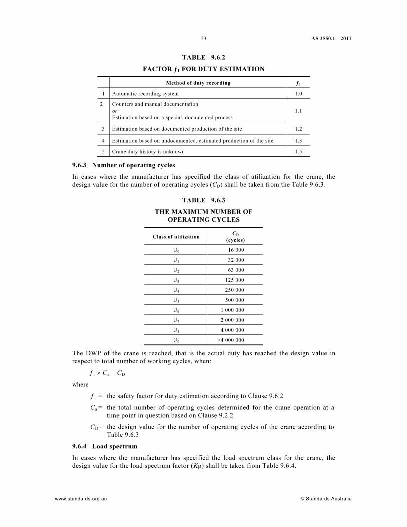
53 AS 2550.1—2011
www.standards.org.au © Standards Australia
TABLE 9.6.2
FACTOR ƒ1 FOR DUTY ESTIMATION
Method of duty recording ƒ1
1 Automatic recording system 1.0
2 Counters and manual documentation
or
Estimation based on a special, documented process
1.1
3 Estimation based on documented production of the site 1.2
4 Estimation based on undocumented, estimated production of the site 1.3
5 Crane duty history is unknown 1.5
9.6.3 Number of operating cycles
In cases where the manufacturer has specified the class of utilization for the crane, the
design value for the number of operating cycles (CD) shall be taken from the Table 9.6.3.
TABLE 9.6.3
THE MAXIMUM NUMBER OF
OPERATING CYCLES
Class of utilization
CD
(cycles)
U0 16 000
U1 32 000
U2 63 000
U3 125 000
U4 250 000
U5 500 000
U6 1 000 000
U7 2 000 000
U8 4 000 000
U9 >4 000 000
The DWP of the crane is reached, that is the actual duty has reached the design value in
respect to total number of working cycles, when:
ƒ1 × Ca = CD
where
ƒ1 = the safety factor for duty estimation according to Clause 9.6.2
Ca = the total number of operating cycles determined for the crane operation at a
time point in question based on Clause 9.2.2
CD= the design value for the number of operating cycles of the crane according to
Table 9.6.3
9.6.4 Load spectrum
In cases where the manufacturer has specified the load spectrum class for the crane, the
design value for the load spectrum factor (Kp) shall be taken from Table 9.6.4.
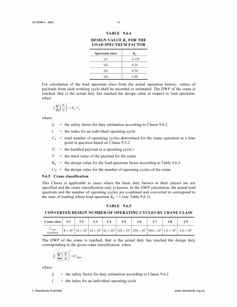
AS 2550.1—2011
© Standards Australia www.standards.org.au
54
TABLE 9.6.4
DESIGN VALUE Kp FOR THE
LOAD SPECTRUM FACTOR
Spectrum class Kp
Q1 0.125
Q2 0.25
Q3 0.50
Q4 1.00
For calculation of the load spectrum class from the actual operation history, values of
payloads from each working cycle shall be recorded or estimated. The DWP of the crane is
reached, that is the actual duty has reached the design value in respect to load spectrum,
when:
∑=
=⎟⎟
⎠
⎞
⎜⎜
⎝
⎛a
1i
Dp
3
i
1
C
CK
P
P
f
where
f1 = the safety factor for duty estimation according to Clause 9.6.2
i = the index for an individual operating cycle
Ca = total number of operating cycles determined for the crane operation at a time
point in question based on Clause 9.2.2
Pi = the handled payload in a operating cycle i
P = the rated value of the payload for the crane
Kp = the design value for the load spectrum factor according to Table 9.6.4
CD = the design value for the number of operating cycles of the crane
9.6.5 Crane classification
This Clause is applicable to cases where the basic duty factors or their classes are not
specified and the crane classification only is known. In the DWP calculation, the actual load
spectrum and the number of operating cycles are combined and converted to correspond to
the state of loading where load spectrum Kp = 1 (see Table 9.6.5).
TABLE 9.6.5
CONVERTED DESIGN NUMBER OF OPERATING CYCLES BY CRANE CLASS
Crane class C1 C2 C3 C4 C5 C6 C7 C8 C9
Cclass
(cycles)
8 × 10³
16 × 103
32 × 103
63 × 103
125 × 103
250 × 103
500 × 103
1.0 × 10⁶
4.0 × 10⁶
The DWP of the crane is reached, that is the actual duty has reached the design duty
corresponding to the given crane classification, when:
class
3
1i
i
1
a
C
P
P
f
C
=⎟
⎠
⎞⎜
⎝
⎛
∑=
where
f1 = the safety factor for duty estimation according to Clause 9.6.2
i = the index for an individual operating cycle
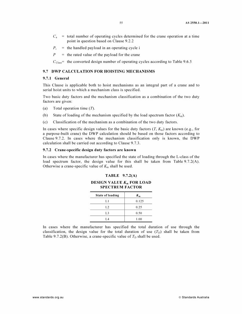
55 AS 2550.1—2011
www.standards.org.au © Standards Australia
Ca = total number of operating cycles determined for the crane operation at a time
point in question based on Clause 9.2.2
Pi = the handled payload in an operating cycle i
P = the rated value of the payload for the crane
CClass
= the converted design number of operating cycles according to Table 9.6.5
9.7 DWP CALCULATION FOR HOISTING MECHANISMS
9.7.1 General
This Clause is applicable both to hoist mechanisms as an integral part of a crane and to
serial hoist units to which a mechanism class is specified.
Two basic duty factors and the mechanism classification as a combination of the two duty
factors are given:
(a) Total operation time (T).
(b) State of loading of the mechanism specified by the load spectrum factor (Km).
(c) Classification of the mechanism as a combination of the two duty factors.
In cases where specific design values for the basic duty factors (T, Km) are known (e.g., for
a purpose-built crane) the DWP calculation should be based on those factors according to
Clause 9.7.2. In cases where the mechanism classification only is known, the DWP
calculation shall be carried out according to Clause 9.7.3.
9.7.2 Crane-specific design duty factors are known
In cases where the manufacturer has specified the state of loading through the L-class of the
load spectrum factor, the design value for this shall be taken from Table 9.7.2(A).
Otherwise a crane-specific value of Km shall be used.
TABLE 9.7.2(A)
DESIGN VALUE Km
FOR LOAD
SPECTRUM FACTOR
State of loading Km
L1 0.125
L2 0.25
L3 0.50
L4 1.00
In cases where the manufacturer has specified the total duration of use through the
classification, the design value for the total duration of use (TD) shall be taken from
Table 9.7.2(B). Otherwise, a crane-specific value of TD shall be used.
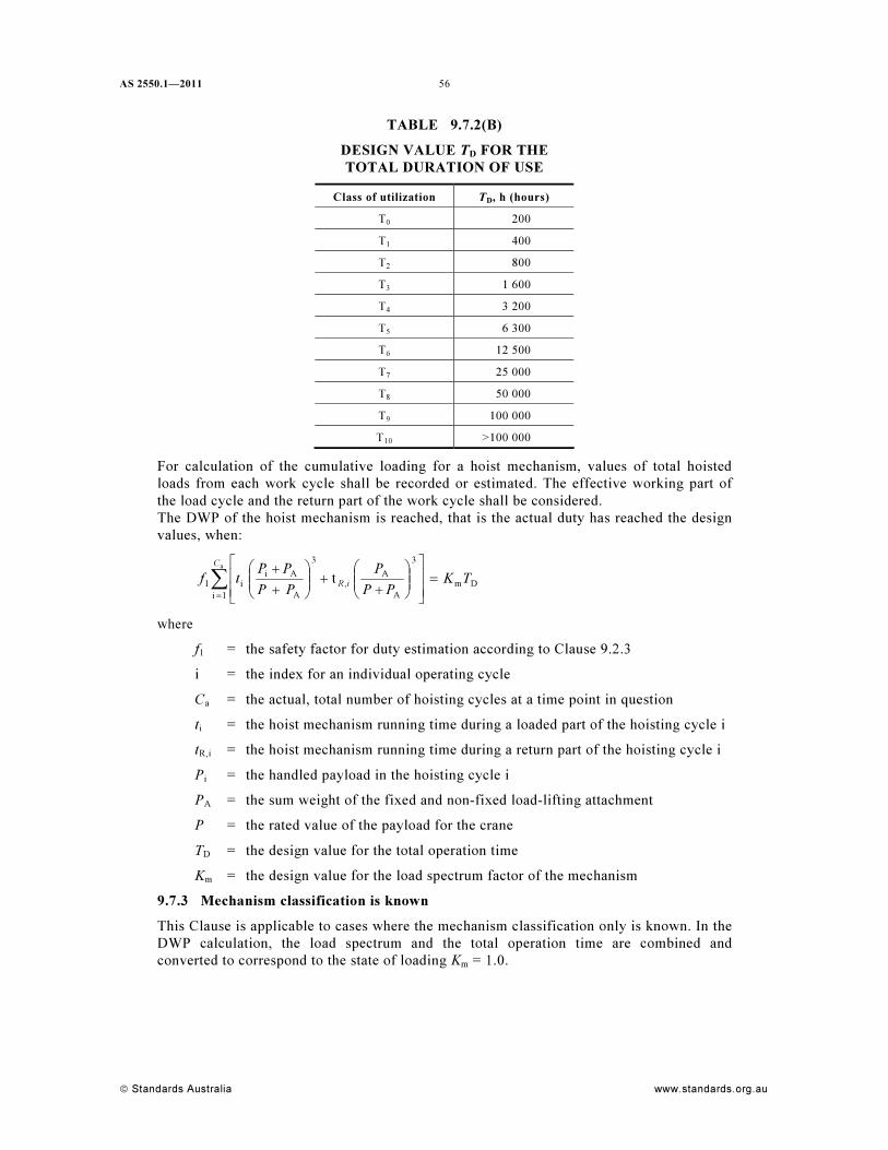
AS 2550.1—2011
© Standards Australia www.standards.org.au
56
TABLE 9.7.2(B)
DESIGN VALUE TD FOR THE
TOTAL DURATION OF USE
Class of utilization TD
, h (hours)
T0 200
T1 400
T2 800
T3 1 600
T4 3 200
T5 6 300
T6 12 500
T7 25 000
T8 50 000
T9 100 000
T10
>100 000
For calculation of the cumulative loading for a hoist mechanism, values of total hoisted
loads from each work cycle shall be recorded or estimated. The effective working part of
the load cycle and the return part of the work cycle shall be considered.
The DWP of the hoist mechanism is reached, that is the actual duty has reached the design
values, when:
Dm
1i
3
A
A
,
3
A
Ai
i1
a
t TK
PP
P
PP
PP
tf
C
iR=
⎥
⎥
⎦
⎤
⎢
⎢
⎣
⎡
⎟⎟
⎠
⎞
⎜⎜
⎝
⎛
+
+⎟⎟
⎠
⎞
⎜⎜
⎝
⎛
+
+
∑=
where
f1 = the safety factor for duty estimation according to Clause 9.2.3
i = the index for an individual operating cycle
Ca = the actual, total number of hoisting cycles at a time point in question
ti = the hoist mechanism running time during a loaded part of the hoisting cycle i
tR,i = the hoist mechanism running time during a return part of the hoisting cycle i
Pi = the handled payload in the hoisting cycle i
PA = the sum weight of the fixed and non-fixed load-lifting attachment
P = the rated value of the payload for the crane
TD = the design value for the total operation time
Km = the design value for the load spectrum factor of the mechanism
9.7.3 Mechanism classification is known
This Clause is applicable to cases where the mechanism classification only is known. In the
DWP calculation, the load spectrum and the total operation time are combined and
converted to correspond to the state of loading Km = 1.0.
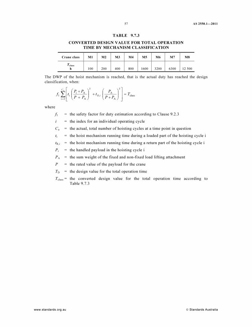
57 AS 2550.1—2011
www.standards.org.au © Standards Australia
TABLE 9.7.3
CONVERTED DESIGN VALUE FOR TOTAL OPERATION
TIME BY MECHANISM CLASSIFICATION
Crane class M1 M2 M3 M4 M5 M6 M7 M8
Tclass
h
100
200
400
800
1600
3200
6300
12 500
The DWP of the hoist mechanism is reached, that is the actual duty has reached the design
classification, when:
class
1i
3
A
A
,
3
A
Ai
i1
a
T
PP
P
t
PP
PP
tf
C
iR=
⎥
⎥
⎦
⎤
⎢
⎢
⎣
⎡
⎟⎟
⎠
⎞
⎜⎜
⎝
⎛
+
+⎟⎟
⎠
⎞
⎜⎜
⎝
⎛
+
+
∑=
where
f1 = the safety factor for duty estimation according to Clause 9.2.3
i = the index for an individual operating cycle
Ca = the actual, total number of hoisting cycles at a time point in question
ti = the hoist mechanism running time during a loaded part of the hoisting cycle i
tR,i = the hoist mechanism running time during a return part of the hoisting cycle i
Pi = the handled payload in the hoisting cycle i
PA = the sum weight of the fixed and non-fixed load lifting attachment
P = the rated value of the payload for the crane
TD = the design value for the total operation time
Tclass = the converted design value for the total operation time according to
Table 9.7.3
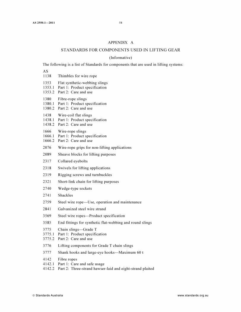
AS 2550.1—2011
© Standards Australia www.standards.org.au
58
APPENDIX A
STANDARDS FOR COMPONENTS USED IN LIFTING GEAR
(Informative)
The following is a list of Standards for components that are used in lifting systems:
AS
1138 Thimbles for wire rope
1353 Flat synthetic-webbing slings
1353.1 Part 1: Product specification
1353.2 Part 2: Care and use
1380 Fibre-rope slings
1380.1 Part 1: Product specification
1380.2 Part 2: Care and use
1438 Wire-coil flat slings
1438.1 Part 1: Product specification
1438.2 Part 2: Care and use
1666 Wire-rope slings
1666.1 Part 1: Product specification
1666.2 Part 2: Care and use
2076 Wire-rope grips for non-lifting applications
2089 Sheave blocks for lifting purposes
2317 Collared eyebolts
2318 Swivels for lifting applications
2319 Rigging screws and turnbuckles
2321 Short-link chain for lifting purposes
2740 Wedge-type sockets
2741 Shackles
2759 Steel wire rope—Use, operation and maintenance
2841 Galvanized steel wire strand
3569 Steel wire ropes—Product specification
3585 End fittings for synthetic flat-webbing and round slings
3775 Chain slings—Grade T
3775.1 Part 1: Product specification
3775.2 Part 2: Care and use
3776 Lifting components for Grade T chain slings
3777 Shank hooks and large-eye hooks—Maximum 60 t
4142 Fibre ropes
4142.1 Part 1: Care and safe usage
4142.2 Part 2: Three-strand hawser-laid and eight-strand plaited
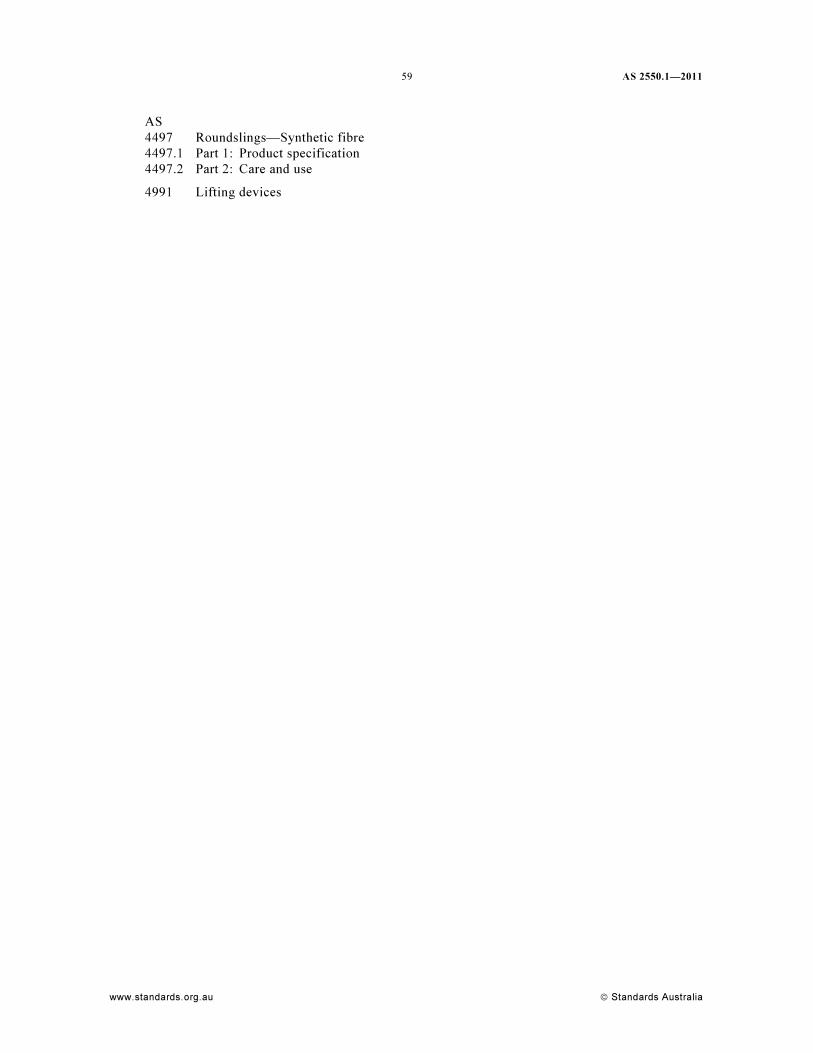
59 AS 2550.1—2011
www.standards.org.au © Standards Australia
AS
4497 Roundslings—Synthetic fibre
4497.1 Part 1: Product specification
4497.2 Part 2: Care and use
4991 Lifting devices
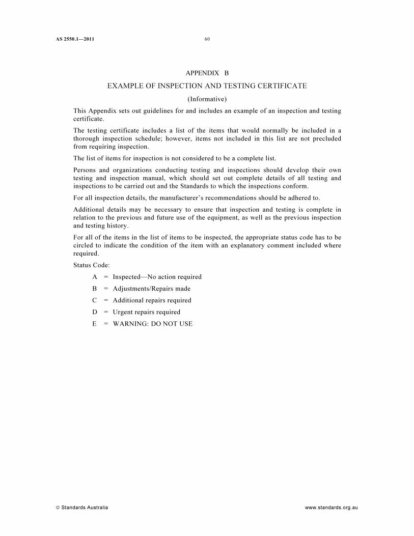
AS 2550.1—2011
© Standards Australia www.standards.org.au
60
APPENDIX B
EXAMPLE OF INSPECTION AND TESTING CERTIFICATE
(Informative)
This Appendix sets out guidelines for and includes an example of an inspection and testing
certificate.
The testing certificate includes a list of the items that would normally be included in a
thorough inspection schedule; however, items not included in this list are not precluded
from requiring inspection.
The list of items for inspection is not considered to be a complete list.
Persons and organizations conducting testing and inspections should develop their own
testing and inspection manual, which should set out complete details of all testing and
inspections to be carried out and the Standards to which the inspections conform.
For all inspection details, the manufacturer’s recommendations should be adhered to.
Additional details may be necessary to ensure that inspection and testing is complete in
relation to the previous and future use of the equipment, as well as the previous inspection
and testing history.
For all of the items in the list of items to be inspected, the appropriate status code has to be
circled to indicate the condition of the item with an explanatory comment included where
required.
Status Code:
A = Inspected—No action required
B = Adjustments/Repairs made
C = Additional repairs required
D = Urgent repairs required
E = WARNING: DO NOT USE
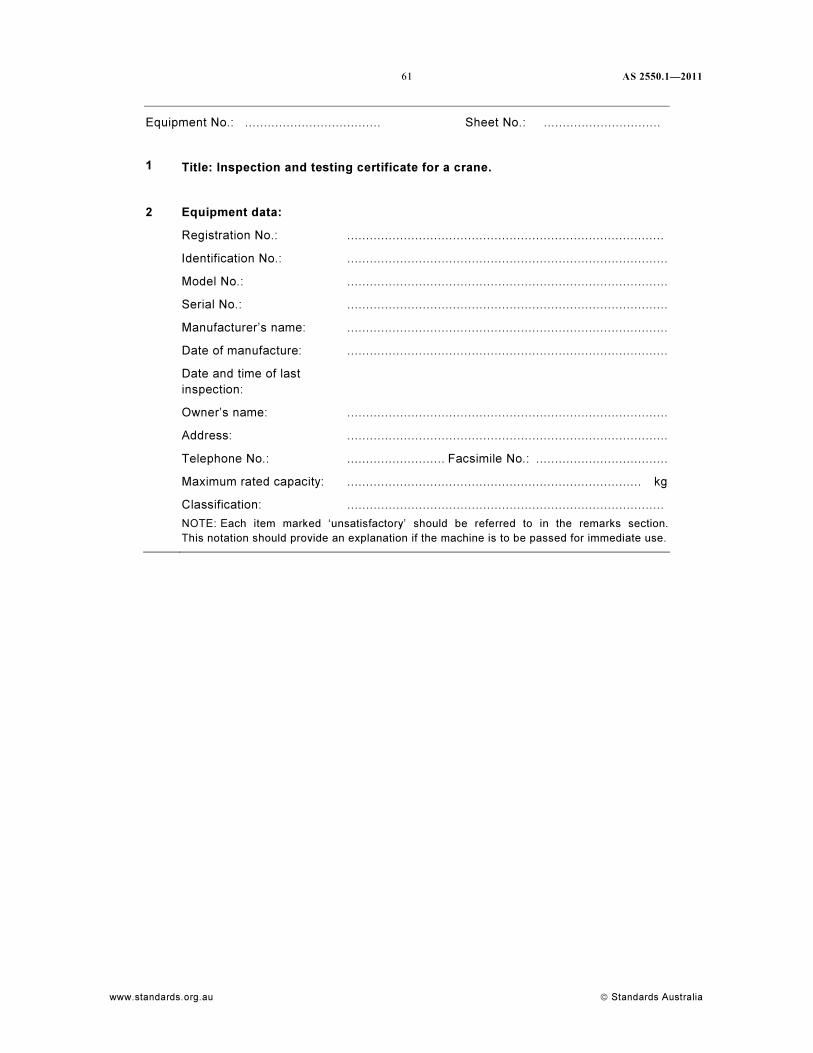
61 AS 2550.1—2011
www.standards.org.au © Standards Australia
Equipment No.: .................................... Sheet No.: ...............................
1 Title: Inspection and testing certificate for a crane.
2 Equipment data:
Registration No.: ....................................................................................
Identification No.: .....................................................................................
Model No.: .....................................................................................
Serial No.: .....................................................................................
Manufacturer’s name: .....................................................................................
Date of manufacture: .....................................................................................
Date and time of last
inspection:
Owner’s name: .....................................................................................
Address: .....................................................................................
Telephone No.: .......................... Facsimile No.: ...................................
Maximum rated capacity: .............................................................................. kg
Classification: ....................................................................................
NOTE: Each item marked ‘unsatisfactory’ should be referred to in the remarks section.
This notation should provide an explanation if the machine is to be passed for immediate use.
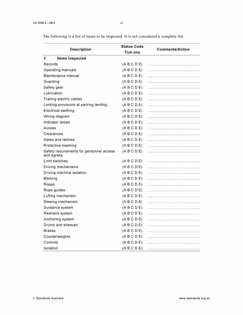
AS 2550.1—2011
© Standards Australia www.standards.org.au
62
The following is a list of items to be inspected. It is not considered a complete list.
Status Code
Description
Tick one
Comments/Action
3 Items inspected
Records (A B C D E) ..............................................
Operating manuals (A B C D E) ..............................................
Maintenance manual (A B C D E) ..............................................
Guarding (A B C D E) ..............................................
Safety gear (A B C D E) ..............................................
Lubrication (A B C D E) ..............................................
Trailing electric cables (A B C D E) ..............................................
Locking provisions at parking landing (A B C D E) ..............................................
Electrical earthing (A B C D E) ..............................................
Wiring diagram (A B C D E) ..............................................
Indicator lamps (A B C D E) ..............................................
Access (A B C D E) ..............................................
Clearances (A B C D E) ..............................................
Gates and latches (A B C D E) ..............................................
Protective meshing (A B C D E) ..............................................
Safety requirements for personnel access
and egress
(A B C D E) ..............................................
Limit switches (A B C D E) ..............................................
Driving mechanisms (A B C D E) ..............................................
Driving machine isolation (A B C D E) ..............................................
Marking (A B C D E) ..............................................
Ropes (A B C D E) ..............................................
Rope guides (A B C D E) ..............................................
Luffing mechanism (A B C D E) ..............................................
Slewing mechanism (A B C D E) ..............................................
Guidance system (A B C D E) ..............................................
Restraint system (A B C D E) ..............................................
Anchoring system (A B C D E) ..............................................
Drums and sheaves (A B C D E) ..............................................
Brakes (A B C D E) ..............................................
Counterweights (A B C D E) ..............................................
Controls (A B C D E) ..............................................
Isolation (A B C D E) ..............................................
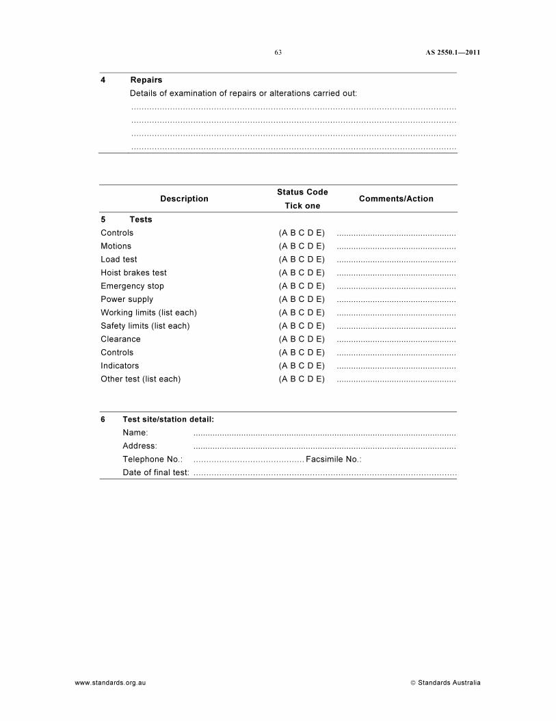
63 AS 2550.1—2011
www.standards.org.au © Standards Australia
4 Repairs
Details of examination of repairs or alterations carried out:
..............................................................................................................................
..............................................................................................................................
..............................................................................................................................
..............................................................................................................................
Status Code
Description
Tick one
Comments/Action
5 Tests
Controls (A B C D E) ...................................................
Motions (A B C D E) ...................................................
Load test (A B C D E) ...................................................
Hoist brakes test (A B C D E) ...................................................
Emergency stop (A B C D E) ...................................................
Power supply (A B C D E) ...................................................
Working limits (list each) (A B C D E) ...................................................
Safety limits (list each) (A B C D E) ...................................................
Clearance (A B C D E) ...................................................
Controls (A B C D E) ...................................................
Indicators (A B C D E) ...................................................
Other test (list each) (A B C D E) ...................................................
6 Test site/station detail:
Name: ...............................................................................................................
Address: ...............................................................................................................
Telephone No.: ........................................... Facsimile No.:
Date of final test: ......................................................................................................
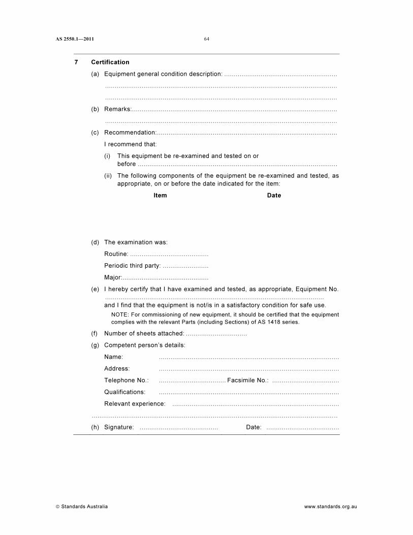
AS 2550.1—2011
© Standards Australia www.standards.org.au
64
7 Certification
(a) Equipment general condition description: ...........................................................
.........................................................................................................................
.........................................................................................................................
(b) Remarks:...........................................................................................................
.........................................................................................................................
(c) Recommendation:..............................................................................................
I recommend that:
(i) This equipment be re-examined and tested on or
before ........................................................................................................
(ii) The following components of the equipment be re-examined and tested, as
appropriate, on or before the date indicated for the item:
Item Date
(d) The examination was:
Routine: .........................................
Periodic third party: ........................
Major:.............................................
(e) I hereby certify that I have examined and tested, as appropriate, Equipment No.
..................................................................................................................
and I find that the equipment is not/is in a satisfactory condition for safe use.
NOTE: For commissioning of new equipment, it should be certified that the equipment
complies with the relevant Parts (including Sections) of AS 1418 series.
(f) Number of sheets attached: ................................
(g) Competent person’s details:
Name: ..............................................................................................
Address: ..............................................................................................
Telephone No.: ................................... Facsimile No.: ...................................
Qualifications: ..............................................................................................
Relevant experience: .......................................................................................
.............................................................................................................................. ..
(h) Signature: ......................................... Date: ......................................
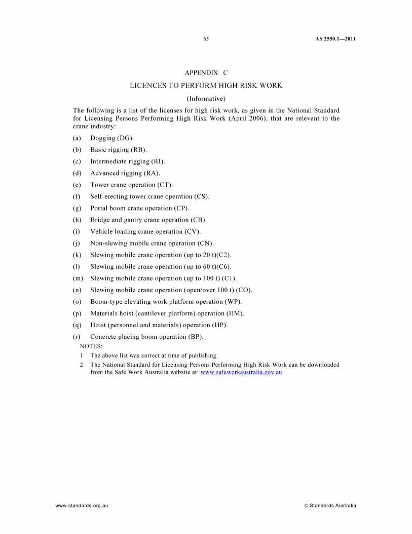
65 AS 2550.1—2011
www.standards.org.au © Standards Australia
APPENDIX C
LICENCES TO PERFORM HIGH RISK WORK
(Informative)
The following is a list of the licenses for high risk work, as given in the National Standard
for Licensing Persons Performing High Risk Work (April 2006), that are relevant to the
crane industry:
(a) Dogging (DG).
(b) Basic rigging (RB).
(c) Intermediate rigging (RI).
(d) Advanced rigging (RA).
(e) Tower crane operation (CT).
(f) Self-erecting tower crane operation (CS).
(g) Portal boom crane operation (CP).
(h) Bridge and gantry crane operation (CB).
(i) Vehicle loading crane operation (CV).
(j) Non-slewing mobile crane operation (CN).
(k) Slewing mobile crane operation (up to 20 t)(C2).
(l) Slewing mobile crane operation (up to 60 t)(C6).
(m) Slewing mobile crane operation (up to 100 t) (C1).
(n) Slewing mobile crane operation (open/over 100 t) (CO).
(o) Boom-type elevating work platform operation (WP).
(p) Materials hoist (cantilever platform) operation (HM).
(q) Hoist (personnel and materials) operation (HP).
(r) Concrete placing boom operation (BP).
NOTES:
1 The above list was correct at time of publishing.
2 The National Standard for Licensing Persons Performing High Risk Work can be downloaded
from the Safe Work Australia website at: www.safeworkaustralia.gov.au
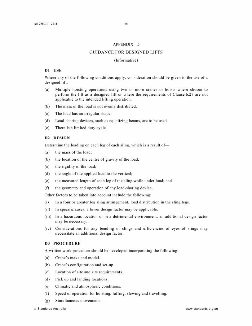
AS 2550.1—2011
© Standards Australia www.standards.org.au
66
APPENDIX D
GUIDANCE FOR DESIGNED LIFTS
(Informative)
D1 USE
Where any of the following conditions apply, consideration should be given to the use of a
designed lift:
(a) Multiple hoisting operations using two or more cranes or hoists where chosen to
perform the lift as a designed lift or where the requirements of Clause 6.27 are not
applicable to the intended lifting operation.
(b) The mass of the load is not evenly distributed.
(c) The load has an irregular shape.
(d) Load-sharing devices, such as equalizing beams, are to be used.
(e) There is a limited duty cycle.
D2 DESIGN
Determine the loading on each leg of each sling, which is a result of—
(a) the mass of the load;
(b) the location of the centre of gravity of the load;
(c) the rigidity of the load;
(d) the angle of the applied load to the vertical;
(e) the measured length of each leg of the sling while under load; and
(f) the geometry and operation of any load-sharing device.
Other factors to be taken into account include the following:
(i) In a four or greater leg sling arrangement, load distribution in the sling legs.
(ii) In specific cases, a lower design factor may be applicable.
(iii) In a hazardous location or in a detrimental environment, an additional design factor
may be necessary.
(iv) Considerations for any bending of slings and efficiencies of eyes of slings may
necessitate an additional design factor.
D3 PROCEDURE
A written work procedure should be developed incorporating the following:
(a) Crane’s make and model.
(b) Crane’s configuration and set-up.
(c) Location of site and site requirements.
(d) Pick up and landing locations.
(e) Climatic and atmospheric conditions.
(f) Speed of operation for hoisting, luffing, slewing and travelling.
(g) Simultaneous movements.
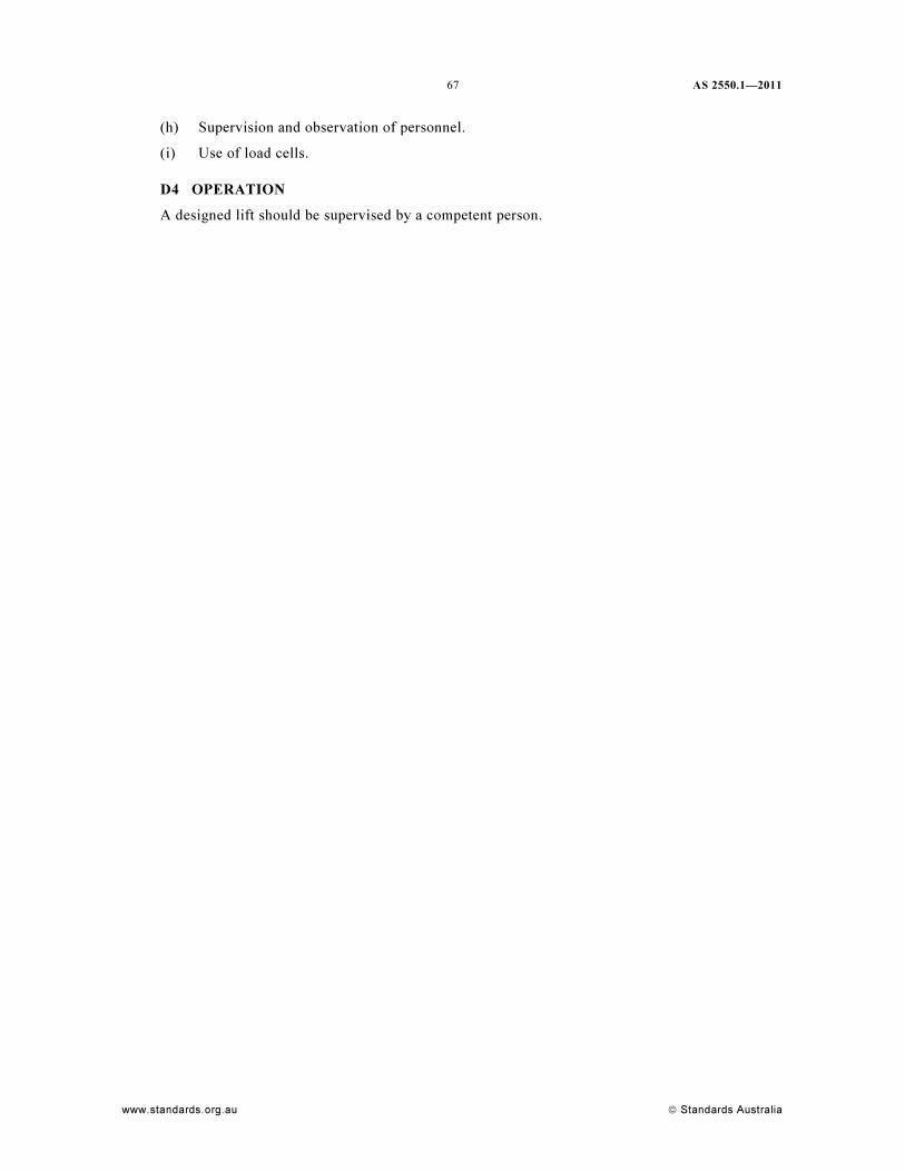
67 AS 2550.1—2011
www.standards.org.au © Standards Australia
(h) Supervision and observation of personnel.
(i) Use of load cells.
D4 OPERATION
A designed lift should be supervised by a competent person.
AS 2550.1—2011
© Standards Australia www.standards.org.au
68
APPENDIX E
SAFE WORK PROCEDURES FOR THE MAINTENANCE AND THE
INSPECTION OF CRANES
(Informative)
E1 SCOPE
This Appendix provides guidance on the safe working procedures for the maintenance and
inspection of cranes.
E2 RESTRICTION OF ACCESS
Personnel should not gain access to a crane or crane superstructure except where such
access is necessary for them to carry out their duties.
E3 AUTHORIZATION FOR ACCESS
Personnel should not gain access to a crane unless authorized.
E4 WARNING TO OTHER PERSONNEL
The person responsible for safety within the area where the crane is located should ensure
that all personnel within the area, and those who may enter the area, are warned of potential
hazard.
E5 WORK NEAR CRANES
Where maintenance or other work needs to be performed near a crane, electric power to the
crane-supply conductors or crane, where applicable, should be disconnected except where
the crane, or part of the crane, needs to be energized to effect maintenance work.
Precautions should be taken to ensure that personnel in the vicinity of the crane are not
subjected to an electrical hazard or a hazard due to movement of the crane.
E6 WORK ON CRANES
Electric power to the crane should be isolated and internal combustion engines should be
stopped except where the crane, or part of the crane, needs to be energized to effect the
maintenance or inspection.
Precautions should be taken to ensure that personnel involved in the maintenance or
inspection of the crane are not subjected to an electrical hazard or a hazard due to
movement of the crane. Where the electric power is not isolated or the internal combustion
engines are not stopped, not less than two persons should be present, one of whom should
be free to take any action necessary to protect personnel in an emergency.
When working on a crane, the following precautions should be observed:
(a) The crane should be taken out of service.
(b) The crane should be moved to a position remote from the operating position, where
applicable.
(c) The crane should be prevented from moving.
(d) Only tools suitable for the purpose should be used.
(e) All maintenance and inspection should be in accordance with instructions written in
accordance with this Standard (see Clause 1.5).
69 AS 2550.1—2011
www.standards.org.au © Standards Australia
E7 LOCK-OUT OF MAIN ISOLATOR OR CRANE ISOLATOR
Where the power supply to the crane is isolated, the main isolator should be locked in the
‘off’ position and the means of unlocking retained by the person responsible for the
maintenance or inspection as nominated in instructions written in accordance with this
Standard.
The person responsible for the maintenance or inspection should ensure that all tools,
equipment and other loose materials have been removed from the crane and its working
area, including crane runways as applicable, and that safe conditions prevail for the
resumption of normal operation of the crane before the power is restored to the crane.
E8 OVERHEAD MAINTENANCE OR INSPECTION
Where overhead maintenance or inspection could create a hazard from falling objects, the
area below should be isolated from surrounding areas and hazard warning signs displayed.
E9 MAINTENANCE AND INSPECTION IN ELEVATED POSITIONS
Where personnel are required to work in elevated positions and there is a danger of falling,
means should be provided to prevent falling. Where fall-arrest harnesses are used, they
should comply with AS/NZS 1891.1.
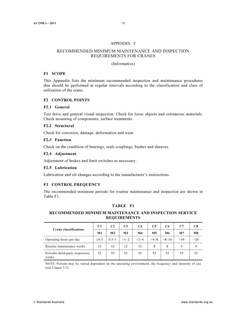
AS 2550.1—2011
© Standards Australia www.standards.org.au
70
APPENDIX F
RECOMMENDED MINIMUM MAINTENANCE AND INSPECTION
REQUIREMENTS FOR CRANES
(Informative)
F1 SCOPE
This Appendix lists the minimum recommended inspection and maintenance procedures
that should be performed at regular intervals according to the classification and class of
utilization of the crane.
F2 CONTROL POINTS
F2.1 General
Test drive and general visual inspection. Check for loose objects and extraneous materials.
Check mounting of components, surface treatments.
F2.2 Structural
Check for corrosion, damage, deformation and wear.
F2.3 Function
Check on the condition of bearings, seals couplings, bushes and sheaves.
F2.4 Adjustment
Adjustment of brakes and limit switches as necessary.
F2.5 Lubrication
Lubrication and oil changes according to the manufacturer’s instructions.
F3 CONTROL FREQUENCY
The recommended minimum periods for routine maintenance and inspection are shown in
Table F1.
TABLE F1
RECOMMENDED MINIMUM MAINTENANCE AND INSPECTION SERVICE
REQUIREMENTS
C1 C2 C3 C4 C5 C6 C7 C8
Crane classifications
M1 M2 M3 M4 M5 M6 M7 M8
Operating hours per day ≥0.5 0.5–1 >1–2 >2–4 >4–8 >8–16 >16 >20
Routine maintenance weeks 12 12 12 12 8 8 4 4
Periodic third-party inspection,
weeks
52 52 52 52 52 52 52 52
NOTE: Periods may be varied dependent on the operating environment, the frequency and intensity of use
(see Clause 7.3).
71 AS 2550.1—2011
www.standards.org.au © Standards Australia
APPENDIX G
CHECKLIST TO DETERMINE SUITABILITY OF MANUFACTURER’S
INSTRUCTIONS
(Normative)
G1 SCOPE
This Appendix sets out a checklist to be used to assess the adequacy of the instructions
available for the crane.
NOTE: The scope of the necessary instructions is described in Clause 1.5.
G2 APPLICATION
The checklist shall be applied to each model type. Where an item can be confirmed as
adequate, the reference section in the Table shall be completed noting the reference Clause
or Section(s) contained in the instructions. Where the item cannot be confirmed as
adequate, the matter shall be referred to the manufacturer or competent person for
assessment and preparation of supplementary instruction.
Where some items contained in the checklists cannot be adequately addressed, the crane
shall be subject to the appropriate series of inspections and maintenance specified in
Clause 7.4.
Crane Make:
Model Number:
Year of manufacture:
Item Description Y/N
(see Note 1)
Reference
(see Note 1)
0 Identification
0.1 The manufacturer’s instructions correspond with the
subject crane (i.e., the model number and serial number
declared in the manual correspond with that on the
crane).
0.2 The owner of the crane is registered with the
manufacturer.
(see Note 2)
1 Use
1.1 The instructions for inspection, maintenance and use
apply to the environment in which the crane is being
used (e.g., at temperatures within the range permitted
by the manufacturer).
1.2 The operating instructions apply to the manner in which
the crane is used.
1.3 Modifications
Instructions have been prepared and addressed any
additional procedures that arise as the result of
modifications to the crane.
1.4 History
There is no history of repeated repairs or defects that
are not addressed in the manufacturer’s instructions.
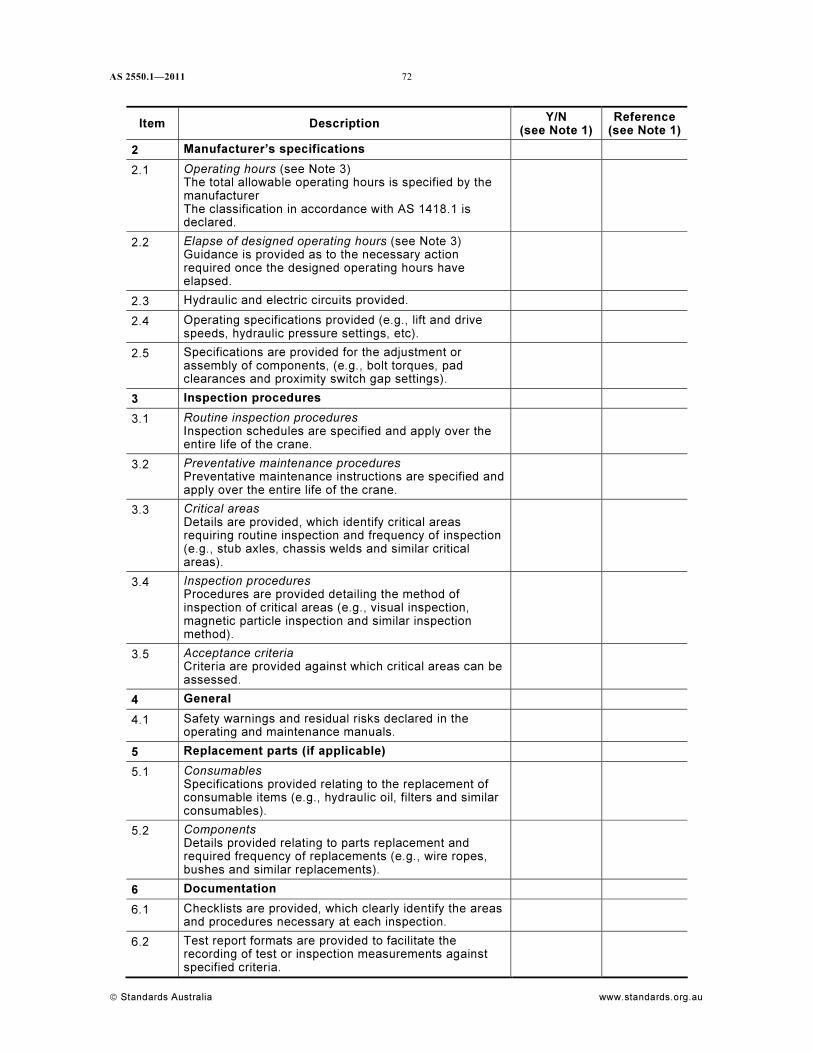
AS 2550.1—2011
© Standards Australia www.standards.org.au
72
Item Description Y/N
(see Note 1)
Reference
(see Note 1)
2 Manufacturer’s specifications
2.1 Operating hours (see Note 3)
The total allowable operating hours is specified by the
manufacturer
The classification in accordance with AS 1418.1 is
declared.
2.2 Elapse of designed operating hours (see Note 3)
Guidance is provided as to the necessary action
required once the designed operating hours have
elapsed.
2.3 Hydraulic and electric circuits provided.
2.4 Operating specifications provided (e.g., lift and drive
speeds, hydraulic pressure settings, etc).
2.5 Specifications are provided for the adjustment or
assembly of components, (e.g., bolt torques, pad
clearances and proximity switch gap settings).
3 Inspection procedures
3.1 Routine inspection procedures
Inspection schedules are specified and apply over the
entire life of the crane.
3.2 Preventative maintenance procedures
Preventative maintenance instructions are specified and
apply over the entire life of the crane.
3.3 Critical areas
Details are provided, which identify critical areas
requiring routine inspection and frequency of inspection
(e.g., stub axles, chassis welds and similar critical
areas).
3.4 Inspection procedures
Procedures are provided detailing the method of
inspection of critical areas (e.g., visual inspection,
magnetic particle inspection and similar inspection
method).
3.5 Acceptance criteria
Criteria are provided against which critical areas can be
assessed.
4 General
4.1 Safety warnings and residual risks declared in the
operating and maintenance manuals.
5 Replacement parts (if applicable)
5.1 Consumables
Specifications provided relating to the replacement of
consumable items (e.g., hydraulic oil, filters and similar
consumables).
5.2 Components
Details provided relating to parts replacement and
required frequency of replacements (e.g., wire ropes,
bushes and similar replacements).
6 Documentation
6.1 Checklists are provided, which clearly identify the areas
and procedures necessary at each inspection.
6.2 Test report formats are provided to facilitate the
recording of test or inspection measurements against
specified criteria.
73 AS 2550.1—2011
www.standards.org.au © Standards Australia
NOTES to Checklist:
1 Where the question is answered in the affirmative, the reference should be quoted. Where the
answer is ‘no’ refer to Paragraph G2.
2 Registration with the manufacturer should be confirmed.
3 ‘Operating hours’ are sometimes expressed as ‘cycles’.
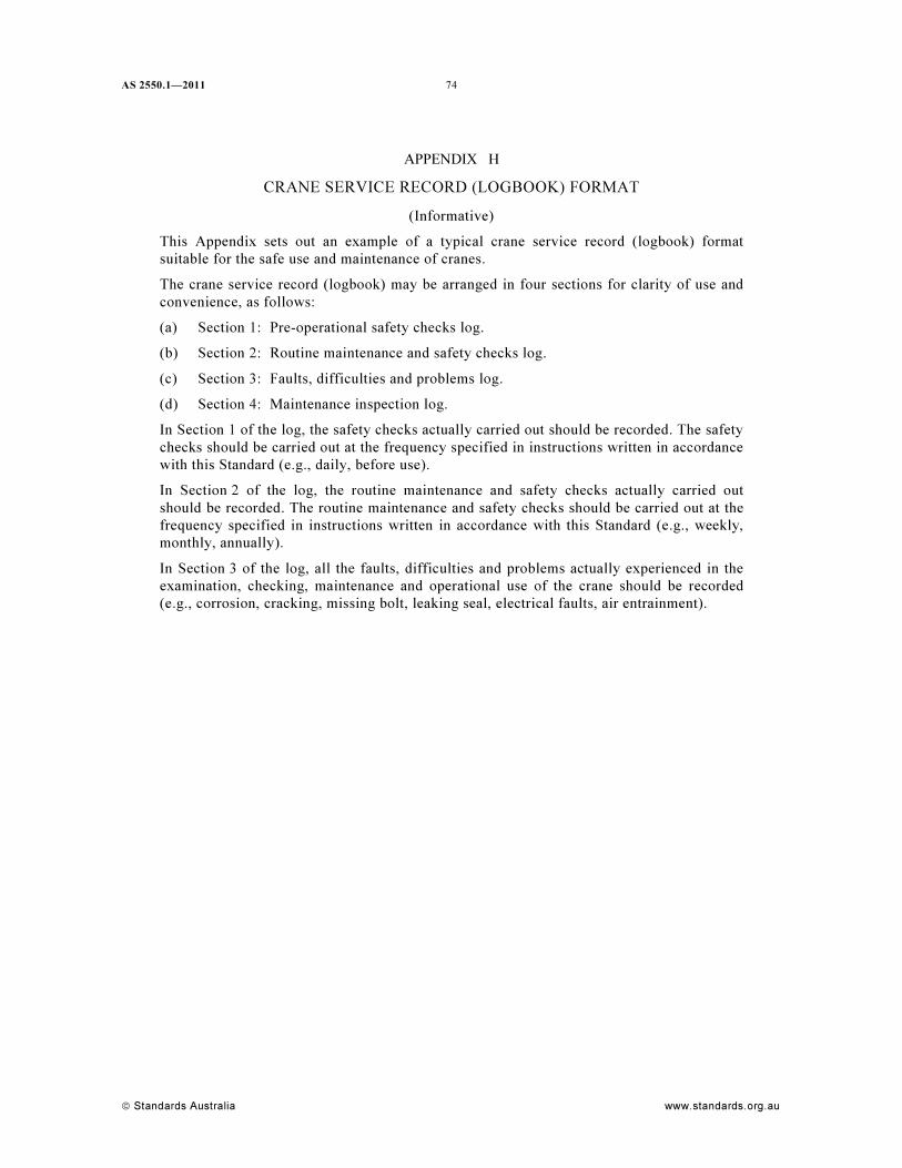
AS 2550.1—2011
© Standards Australia www.standards.org.au
74
APPENDIX H
CRANE SERVICE RECORD (LOGBOOK) FORMAT
(Informative)
This Appendix sets out an example of a typical crane service record (logbook) format
suitable for the safe use and maintenance of cranes.
The crane service record (logbook) may be arranged in four sections for clarity of use and
convenience, as follows:
(a) Section 1: Pre-operational safety checks log.
(b) Section 2: Routine maintenance and safety checks log.
(c) Section 3: Faults, difficulties and problems log.
(d) Section 4: Maintenance inspection log.
In Section 1 of the log, the safety checks actually carried out should be recorded. The safety
checks should be carried out at the frequency specified in instructions written in accordance
with this Standard (e.g., daily, before use).
In Section 2 of the log, the routine maintenance and safety checks actually carried out
should be recorded. The routine maintenance and safety checks should be carried out at the
frequency specified in instructions written in accordance with this Standard (e.g., weekly,
monthly, annually).
In Section 3 of the log, all the faults, difficulties and problems actually experienced in the
examination, checking, maintenance and operational use of the crane should be recorded
(e.g., corrosion, cracking, missing bolt, leaking seal, electrical faults, air entrainment).
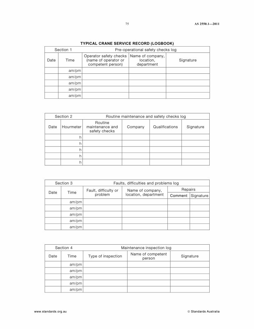
75 AS 2550.1—2011
www.standards.org.au © Standards Australia
TYPICAL CRANE SERVICE RECORD (LOGBOOK)
Section 1 Pre-operational safety checks log
Date Time Operator safety checks
(name of operator or competent person)
Name of company, location,
department Signature
am/pm
am/pm
am/pm
am/pm
am/pm
Section 2 Routine maintenance and safety checks log
Date HourmeterRoutine
maintenance and safety checks
Company Qualifications Signature
h
h
h
h
h
Section 3 Faults, difficulties and problems log
Repairs Date Time Fault, difficulty or
problem Name of company,
location, department Comment Signature
am/pm
am/pm
am/pm
am/pm
am/pm
Section 4 Maintenance inspection log
Date Time Type of inspection Name of competent person Signature
am/pm
am/pm
am/pm
am/pm
am/pm
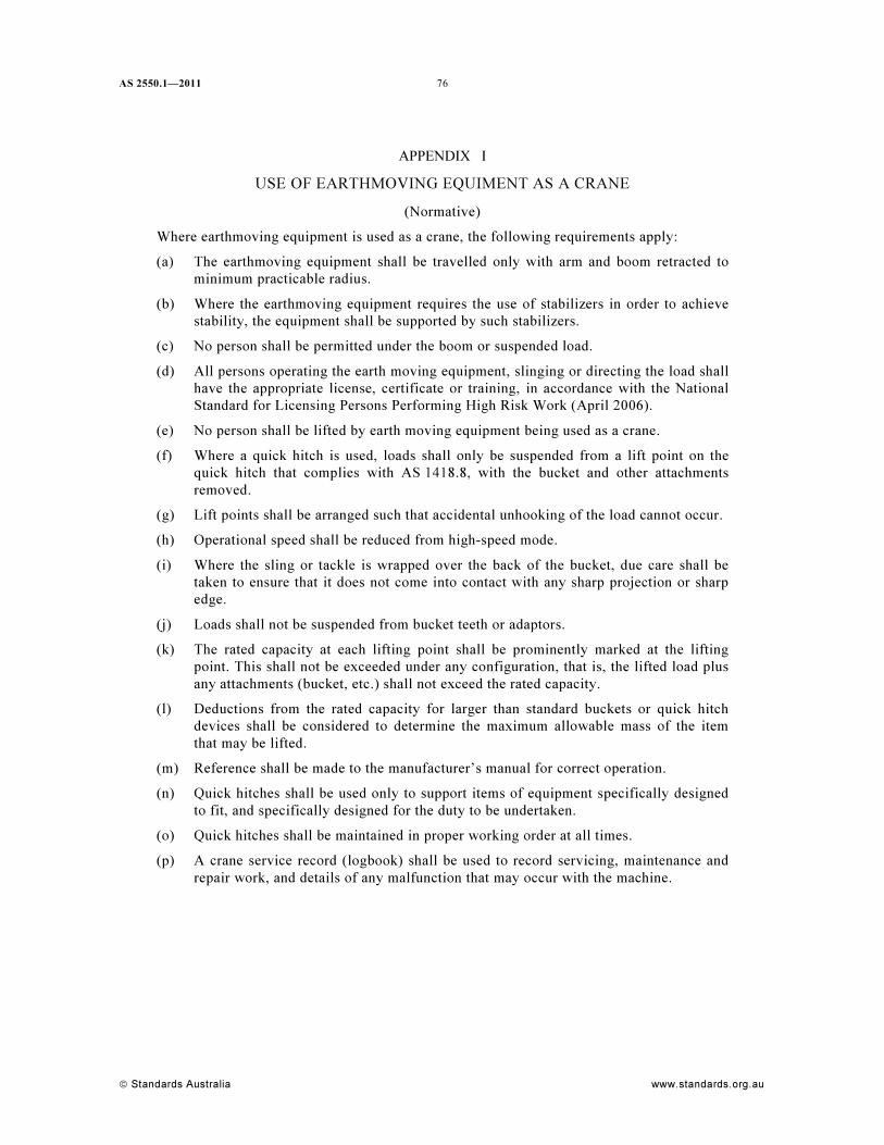
AS 2550.1—2011
© Standards Australia www.standards.org.au
76
APPENDIX I
USE OF EARTHMOVING EQUIMENT AS A CRANE
(Normative)
Where earthmoving equipment is used as a crane, the following requirements apply:
(a) The earthmoving equipment shall be travelled only with arm and boom retracted to
minimum practicable radius.
(b) Where the earthmoving equipment requires the use of stabilizers in order to achieve
stability, the equipment shall be supported by such stabilizers.
(c) No person shall be permitted under the boom or suspended load.
(d) All persons operating the earth moving equipment, slinging or directing the load shall
have the appropriate license, certificate or training, in accordance with the National
Standard for Licensing Persons Performing High Risk Work (April 2006).
(e) No person shall be lifted by earth moving equipment being used as a crane.
(f) Where a quick hitch is used, loads shall only be suspended from a lift point on the
quick hitch that complies with AS 1418.8, with the bucket and other attachments
removed.
(g) Lift points shall be arranged such that accidental unhooking of the load cannot occur.
(h) Operational speed shall be reduced from high-speed mode.
(i) Where the sling or tackle is wrapped over the back of the bucket, due care shall be
taken to ensure that it does not come into contact with any sharp projection or sharp
edge.
(j) Loads shall not be suspended from bucket teeth or adaptors.
(k) The rated capacity at each lifting point shall be prominently marked at the lifting
point. This shall not be exceeded under any configuration, that is, the lifted load plus
any attachments (bucket, etc.) shall not exceed the rated capacity.
(l) Deductions from the rated capacity for larger than standard buckets or quick hitch
devices shall be considered to determine the maximum allowable mass of the item
that may be lifted.
(m) Reference shall be made to the manufacturer’s manual for correct operation.
(n) Quick hitches shall be used only to support items of equipment specifically designed
to fit, and specifically designed for the duty to be undertaken.
(o) Quick hitches shall be maintained in proper working order at all times.
(p) A crane service record (logbook) shall be used to record servicing, maintenance and
repair work, and details of any malfunction that may occur with the machine.
Standards Australia Standards Australia develops Australian Standards® and other documents of public benefit and national interest. These Standards are developed through an open process of consultation and consensus, in which all interested parties are invited to participate. Through a Memorandum of Understanding with the Commonwealth Government, Standards Australia is recognized as Australia’s peak non-government national standards body. Standards Australia also supports excellence in design and innovation through the Australian Design Awards. For further information visit www.standards.org.au Australian Standards® Committees of experts from industry, governments, consumers and other relevant sectors prepare Australian Standards. The requirements or recommendations contained in published Standards are a consensus of the views of representative interests and also take account of comments received from other sources. They reflect the latest scientific and industry experience. Australian Standards are kept under continuous review after publication and are updated regularly to take account of changing technology. International Involvement Standards Australia is responsible for ensuring the Australian viewpoint is considered in the formulation of International Standards and that the latest international experience is incorporated in national Standards. This role is vital in assisting local industry to compete in international markets. Standards Australia represents Australia at both the International Organization for Standardization (ISO) and the International Electrotechnical Commission (IEC). Sales and Distribution Australian Standards®, Handbooks and other documents developed by Standards Australia are printed and distributed under license by SAI Global Limited.
For information regarding the development of Standards contact: Standards Australia Limited GPO Box 476 Sydney NSW 2001 Phone: 02 9237 6000 Fax: 02 9237 6010 Email: [email protected] Internet: www.standards.org.au For information regarding the sale and distribution of Standards contact: SAI Global Limited Phone: 13 12 42 Fax: 1300 65 49 49 Email: [email protected]
ISBN 978 0 7337 9786 6

This page has been left intentionally blank.