Embed Size (px)
Citation preview
CRANEX DDigital Panoramic
andCephalometric
X-ray Unit(Version 3)
User’s Manual
Number 203371 rev. 1 (0812)
EN

Cranex D
User‘s Manual 203371 i
Cranex DDigital Panoramic
and CephalometricX-ray Unit(Version 3)
User’s Manual
Medical Device Directive93/42/EEC
Number 203371 rev. 1 (0812)Original approved English language version
Manufactured by SOREDEXNahkelantie 160, Tuusula
P.O. BOX 148FI-04301 Tuusula,
FinlandTel. +358 (0)45 7882 2000
Fax. + 358 9 701 5261

Cranex D
ii User’s Manual 203371
Soredex endeavours to produce product documentation that is accurate and up todate. However, our policy of continual product development may result in changesto products that are not reflected in the product documentation. Therefore, thisdocument should not be regarded as an infallible guide to current product specifi-cations. Soredex maintains the right to make changes and alterations without priornotice.

Cranex D
User‘s Manual 203371 iii
Contents
1. Introduction....................................................................................................... 11.1 Cranex D digital X-ray unit ............................................................................. 11.2 About this manual .......................................................................................... 1
2. Unit description ................................................................................................ 22.1 Cranex D ...................................................................................................... 22.2 Optional cephalometric device ...................................................................... 32.3 Control panel ................................................................................................. 42.4 User interface ............................................................................................... 52.5 Accessories .................................................................................................. 6
3. Taking Panoramic Exposures ......................................................................... 73.1 Preparing the PC .......................................................................................... 73.2 Preparing the Unit ......................................................................................... 83.3 Taking a panoramic exposure ....................................................................... 9
Selecting the panoramic program ............................................................... 9Positioning the patient for a panoramic exposure ..................................... 10Taking a panoramic exposure ................................................................... 15After taking a panoramic exposure ........................................................... 17
3.4 Taking a temporomandibular joint exposure ................................................. 18Selecting the TMJ program....................................................................... 18Positioning the patient for TMJ exposures ................................................ 18Taking TMJ exposures .............................................................................. 19After taking TMJ exposures ...................................................................... 22
3.5 Taking a sinus exposure .............................................................................. 23Selecting the sinus program ..................................................................... 23Positioning the patient for a Sinus exposure ............................................. 23Taking a Sinus exposure ........................................................................... 25After taking a Sinus exposure ................................................................... 26
4. Taking cephalometric exposures (Ceph option) .......................................... 274.1 Preparing the PC ........................................................................................ 274.2 Preparing the unit ........................................................................................ 274.3 Taking a cephalometric exposure ................................................................ 28
Selecting the cephalometric program ....................................................... 28Positioning the patient .............................................................................. 29Taking an exposure .................................................................................. 31After exposure .......................................................................................... 33
Cranex D
iv User’s Manual 203371
5. Carpus exposures (Not in USA) .................................................................... 346. Using the unit without x-rays......................................................................... 367. Attaching and removing the CCD sensor ..................................................... 37
7.1 Attaching the sensor .................................................................................... 377.2 Removing the sensor .................................................................................. 38
8. Exposure switch lock ..................................................................................... 398.1 Unlocking the exposure switch..................................................................... 398.2 Locking the exposure switch ....................................................................... 39
9. Unit setup ........................................................................................................ 409.1 Setup options .............................................................................................. 409.2 Image Preview ............................................................................................ 42
10. Troubleshooting and maintenance ............................................................. 4410.1 Error messages ........................................................................................ 44
User Errors ............................................................................................... 44Unit Errors ................................................................................................ 47Other operating problems ......................................................................... 49
10.2 Care and Maintenance .............................................................................. 50Cleaning and disinfecting the unit ............................................................. 50
Enamelled surfaces ........................................................................ 50Positioning mirror and light lenses .................................................. 50Surfaces that the patient touches .................................................... 50
Correct operation of the unit ...................................................................... 50Yearly maintenance .................................................................................. 51Disposal ................................................................................................... 51
11. Warnings and precautions ........................................................................... 52Appendix A - Technical Information ............................................................... A - 1
A.1 Technical specifications ........................................................................... A - 1A.2 Unit dimensions ....................................................................................... A - 6A.3 Symbols that appear on the unit ............................................................... A - 7
User ‘s Manual 203371 1
Cranex D 1. Introduction
1. Introduction1.1 Cranex D digital X-ray unit
The Cranex D is a digital dental x-ray unit designedto take images of the dento-maxillo-facial complex ofthe human skull. It can be used to take:- adult panoramic exposures,- child panoramic exposures
(reduced width and height),- partial panoramic exposures- sinus exposures,- and TMJ exposures.
An optional cephalometric device allows ceph andcarpus (not USA) exposures to be taken.
Both the unit and the cephalometric device use CCDsensors as the image receptor and a PC with theUser Interface and suitable dental imaging software,such as Digora for Windows (not in USA), to handlethe digital dental images.
1.2 About this manualThis manual describes how to use the Cranex Ddigital dental x-ray unit and the optional cephalometricdevice.
Please read these instructions and the Warningsand Precautions in section “11. Warnings andPrecautions”, before operating the unit.
NOTE:Instructions starting with PC: for example:“1. PC: Open a patient card” indicate that the task iscarried out from the PC.Instructions NOT starting with PC: for example:“3. Close the head supports” indicate that the task iscarried out from the UNIT.

2 User’s manual 203371
2. Unit description Cranex D
2. Unit description
2.1 Cranex D
User’s manual 203371 3
Cranex D 2. Unit description
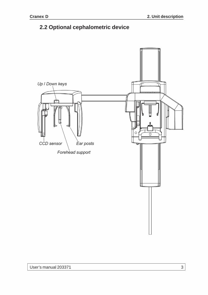
2.2 Optional cephalometric device
4 User’s manual 203371
2. Unit description Cranex D
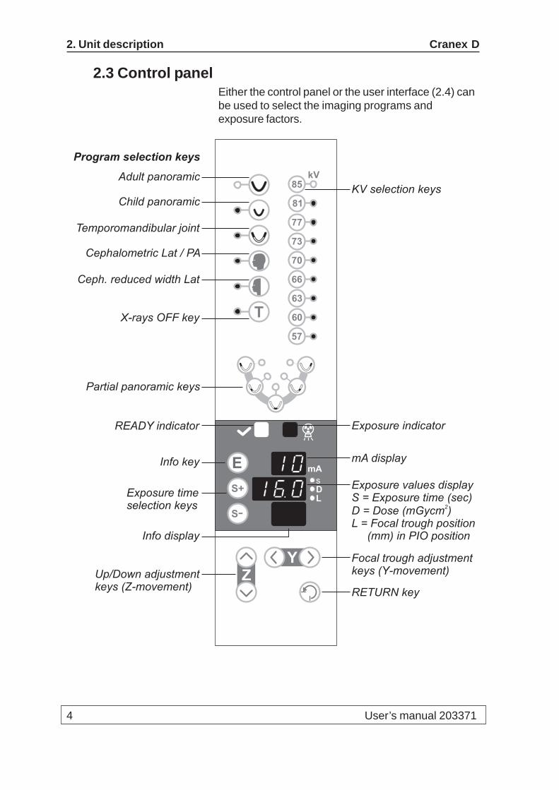
2.3 Control panelEither the control panel or the user interface (2.4) canbe used to select the imaging programs andexposure factors.
Focal trough adjustmentkeys (Y-movement)
RETURN key
Up/Down adjustmentkeys (Z-movement)
Adult panoramic
Child panoramic
Temporomandibular joint
Cephalometric Lat / PA
Ceph. reduced width Lat
Program selection keys
Partial panoramic keys
Exposure timeselection keys
KV selection keys
X-rays OFF key
Exposure values displayS = Exposure time (sec)D = Dose (mGycm )L = Focal trough position
(mm) in PIO position
2
mA display
Exposure indicator
ZY
mA
DL
E
S+
S-
s
81
T
kV85
77
73
70
66
63
60
57
Info key
READY indicator
Info display

User’s manual 203371 5
Cranex D 2. Unit description
2.4 User interface
! E
7
rEL
“Always on top” key
Error code display
Scroll up/down keys
!
S+
S-
10.0 mA
10.8 s
1.3 mGycm2
Cranex D x-
T
81
kV85
77
73
70
66
63
60
57
Info key

6 User’s manual 203371
2. Unit description Cranex D
2.5 Accessories
Chin rest - 9802612
Disposable cover for chin rest - 6801140
Bite block - 6811860
Disposable cover for bite block - 6801120
Lip support - 6811880
Disposable cover for lip support - 6801130
Lip holder - 6811870
Disposable covers for cephalometric ear cones - 6801150
Cranex D 3. Panoramic Exposures
User’s manual 203371 7
3. Taking Panoramic Exposures
3.1 Preparing the PC1. PC: Switch on the PC that is connected to the
unit.
2. PC: Open the dental imaging software and thenopen a new or existing patient card for the patient.For information on how to do this refer to theuser’s guide supplied with the dental imagingsoftware.
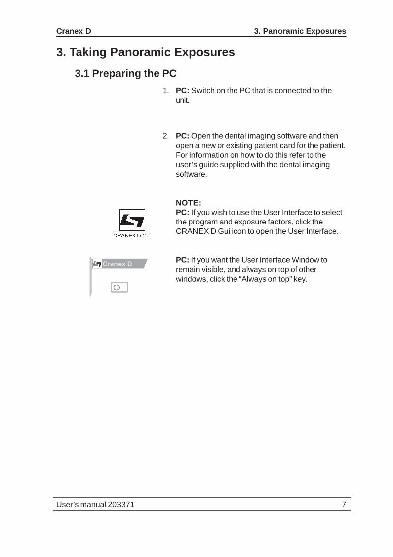
NOTE:PC: If you wish to use the User Interface to selectthe program and exposure factors, click theCRANEX D Gui icon to open the User Interface.
PC: If you want the User Interface Window toremain visible, and always on top of otherwindows, click the “Always on top” key.
Cranex D

8 User’s manual 203371
3. Panoramic Exposures Cranex D
3.2 Preparing the Unit1. Attach the CCD sensor to the sensor holder on
the rotating unit if it is not already attached.For information on how to attach and remove theCCD sensor, see section “7 Attaching andremoving the CCD sensor”.
2. Press the ON / OFF switch, on the rear, right-handside of the unit, to the on position (I) to switch theunit on. The unit will carry out a self test duringwhich the display lights will come on.
3. Press the RETURN key to drive the rotating unit tothe patient-in-out (PIO) position.
The READY light will come on and rotating unit willautomatically move to the 0 mm focal troughposition.
If the READY light does not come on refer tosection “10.1 Error messages”.
DL
s
Cranex D 3. Panoramic Exposures
User’s manual 203371 9
3.3 Taking a panoramic exposure
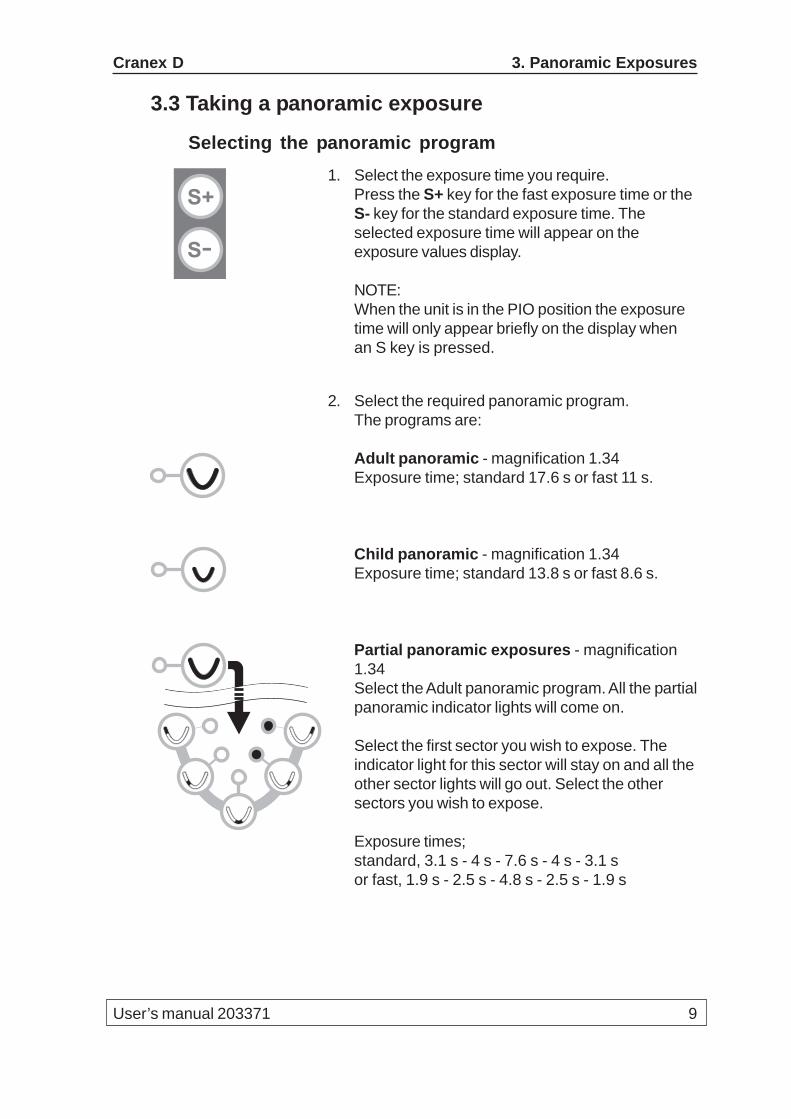
Selecting the panoramic program1. Select the exposure time you require.
Press the S+ key for the fast exposure time or theS- key for the standard exposure time. Theselected exposure time will appear on theexposure values display.
NOTE:When the unit is in the PIO position the exposuretime will only appear briefly on the display whenan S key is pressed.
2. Select the required panoramic program.The programs are:
Adult panoramic - magnification 1.34Exposure time; standard 17.6 s or fast 11 s.
Child panoramic - magnification 1.34Exposure time; standard 13.8 s or fast 8.6 s.
Partial panoramic exposures - magnification1.34Select the Adult panoramic program. All the partialpanoramic indicator lights will come on.
Select the first sector you wish to expose. Theindicator light for this sector will stay on and all theother sector lights will go out. Select the othersectors you wish to expose.
Exposure times;standard, 3.1 s - 4 s - 7.6 s - 4 s - 3.1 sor fast, 1.9 s - 2.5 s - 4.8 s - 2.5 s - 1.9 s
S+
S-
10 User’s manual 203371
3. Panoramic Exposures Cranex D
Positioning the patient for a panoramic exposureNOTE:If the patient appears nervous you may want to reas-sure the patient by demonstrating how the unit works.To do this see section “6. Using the unit without x-rays”.
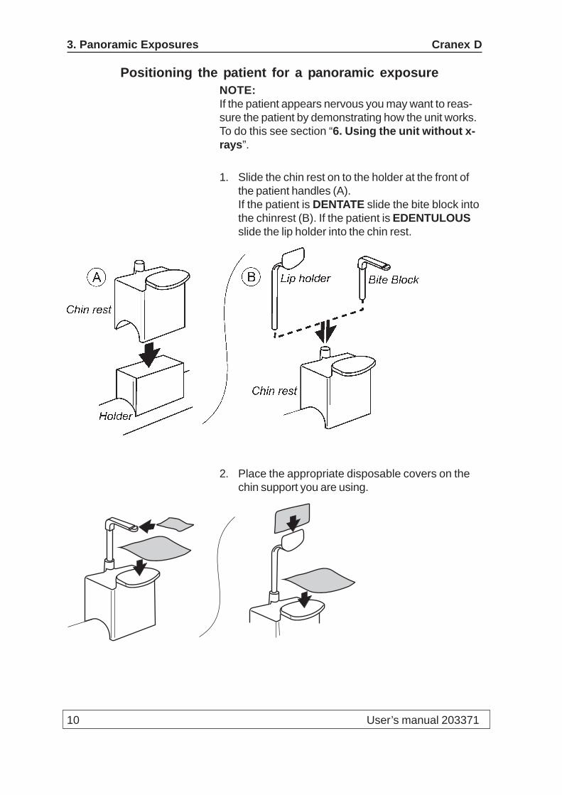
1. Slide the chin rest on to the holder at the front ofthe patient handles (A).If the patient is DENTATE slide the bite block intothe chinrest (B). If the patient is EDENTULOUSslide the lip holder into the chin rest.
2. Place the appropriate disposable covers on thechin support you are using.

Cranex D 3. Panoramic Exposures
User’s manual 203371 11
3. Ask the patient to remove any spectacles andfalse teeth and any jewellery or metal objects fromtheir face, ears or neck. Also ask them to removeany hair clips or pins.
4. Place a protective lead apron over the patient’sshoulders.
5. Press the height adjusting keys to adjust theheight of the chin support until it is slightly higherthan the patient’s chin.
6. If the patient is DENTATE ask them to grasp thepatient handles, place their chin on the chin restand bite the bite block.The biting edges of the patient’s upper and lowerincisors must be positioned in the respectivenotches in the top and bottom of the bite block.
If the patient is EDENTULOUS ask them to placetheir chin on the chin rest and press their top lipagainst the lip holder.
Z

12 User’s manual 203371
3. Panoramic Exposures Cranex D
7. Open the mirror so that you can see a reflection ofthe patient in the mirror. The patient positioninglights will come on.
NOTE:The lights will remain on for 30 seconds. If youneed more time briefly press one of the focaltrough light adjusting keys.
8. Look at the reflection of the patient in the mirrorand position the midsagittal plane of the patientso that it coincides with the midsagittal plane light.The patient’s head must be positioned symmetri-cally and the patient must be looking straightahead.The patient’s head must NOT be tilted or turned toone side.
Y
Cranex D 3. Panoramic Exposures
User’s manual 203371 13
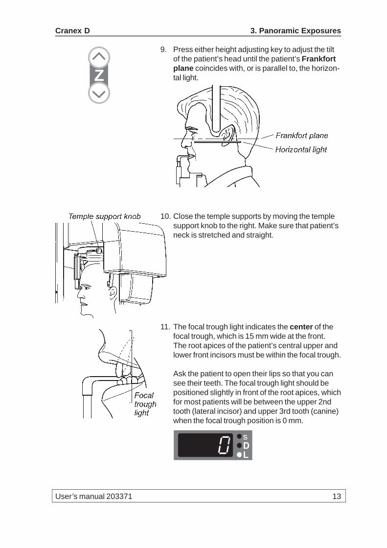
9. Press either height adjusting key to adjust the tiltof the patient’s head until the patient’s Frankfortplane coincides with, or is parallel to, the horizon-tal light.
10. Close the temple supports by moving the templesupport knob to the right. Make sure that patient’sneck is stretched and straight.
11. The focal trough light indicates the center of thefocal trough, which is 15 mm wide at the front.The root apices of the patient’s central upper andlower front incisors must be within the focal trough.
Ask the patient to open their lips so that you cansee their teeth. The focal trough light should bepositioned slightly in front of the root apices, whichfor most patients will be between the upper 2ndtooth (lateral incisor) and upper 3rd tooth (canine)when the focal trough position is 0 mm.
Z
DL
s
14 User’s manual 203371
3. Panoramic Exposures Cranex D
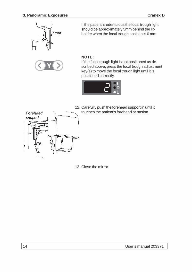
If the patient is edentulous the focal trough lightshould be approximately 5mm behind the lipholder when the focal trough position is 0 mm.
NOTE:If the focal trough light is not positioned as de-scribed above, press the focal trough adjustmentkey(s) to move the focal trough light until it ispositioned correctly.
12. Carefully push the forehead support in until ittouches the patient’s forehead or nasion.
13. Close the mirror.
Y
DL
s
Cranex D 3. Panoramic Exposures
User’s manual 203371 15
Taking a panoramic exposure1. Check once more that the patient has not moved
and is positioned correctly for a panoramicexposure.
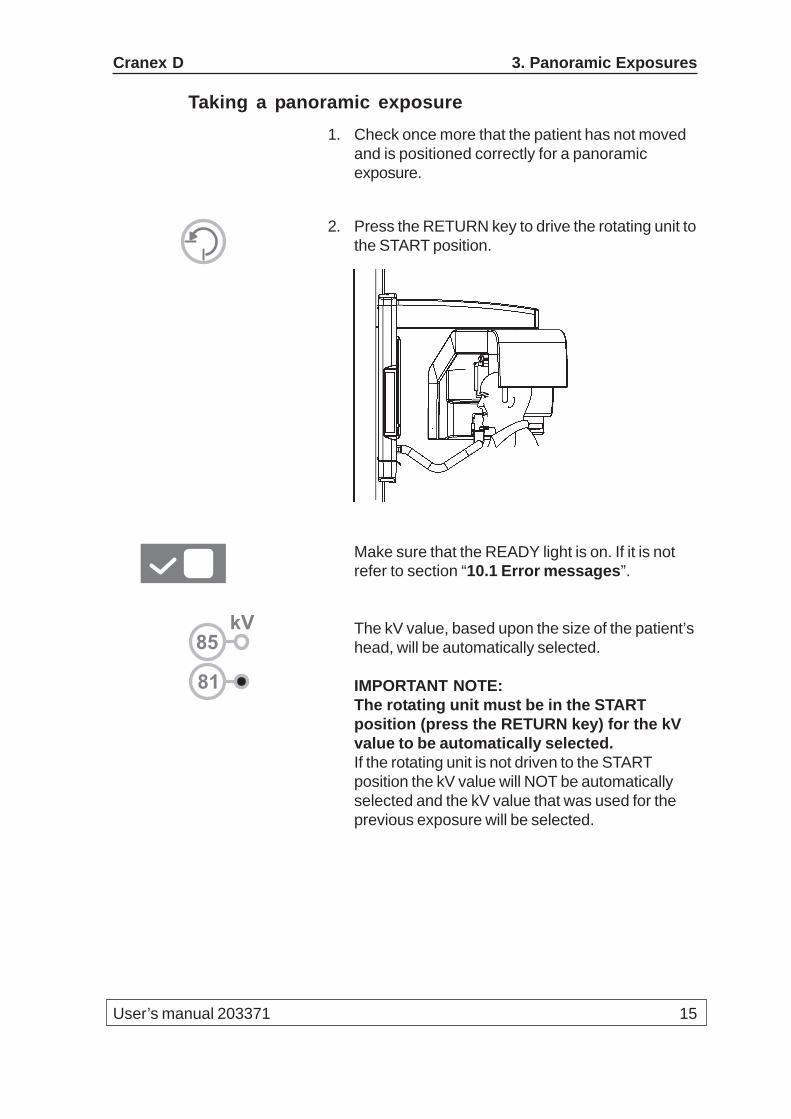
2. Press the RETURN key to drive the rotating unit tothe START position.
Make sure that the READY light is on. If it is notrefer to section “10.1 Error messages”.
The kV value, based upon the size of the patient’shead, will be automatically selected.
IMPORTANT NOTE:The rotating unit must be in the STARTposition (press the RETURN key) for the kVvalue to be automatically selected.If the rotating unit is not driven to the STARTposition the kV value will NOT be automaticallyselected and the kV value that was used for theprevious exposure will be selected.
81
kV85
16 User’s manual 203371
3. Panoramic Exposures Cranex D
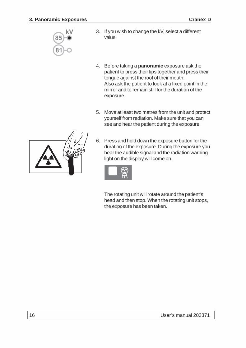
3. If you wish to change the kV, select a differentvalue.
4. Before taking a panoramic exposure ask thepatient to press their lips together and press theirtongue against the roof of their mouth.Also ask the patient to look at a fixed point in themirror and to remain still for the duration of theexposure.
5. Move at least two metres from the unit and protectyourself from radiation. Make sure that you cansee and hear the patient during the exposure.
6. Press and hold down the exposure button for theduration of the exposure. During the exposure youhear the audible signal and the radiation warninglight on the display will come on.
The rotating unit will rotate around the patient’shead and then stop. When the rotating unit stops,the exposure has been taken.
81
kV85
Cranex D 3. Panoramic Exposures
User’s manual 203371 17
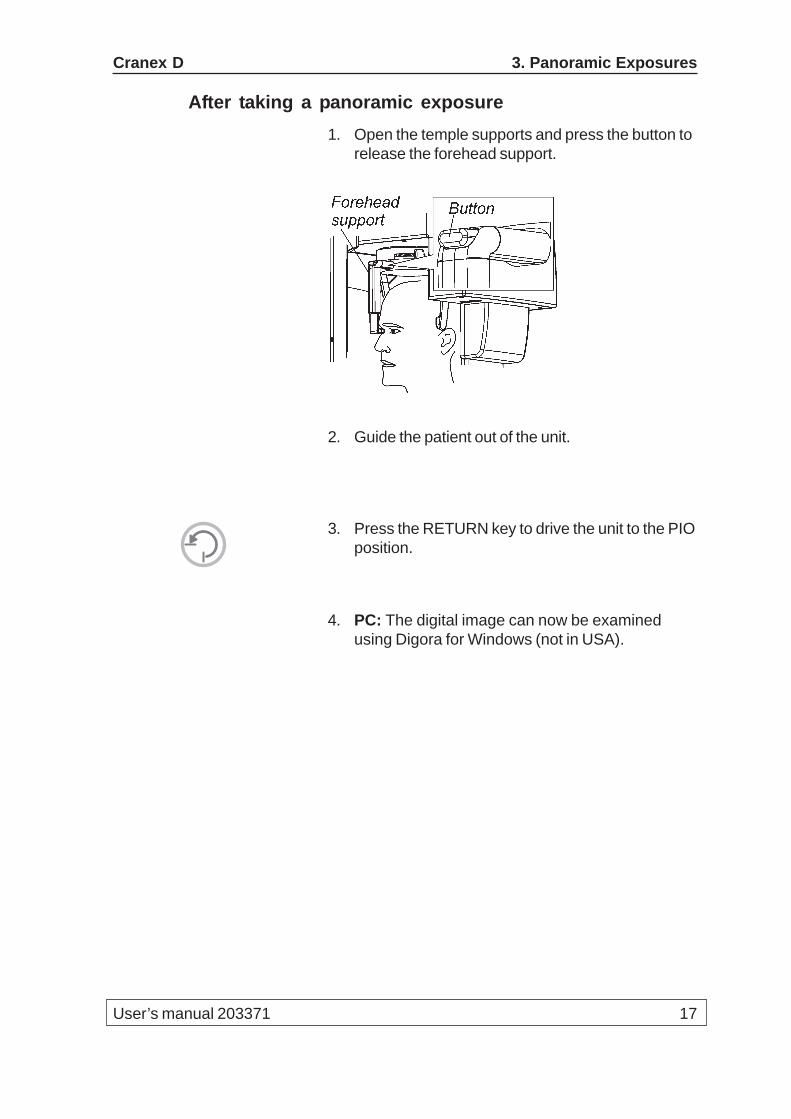
After taking a panoramic exposure1. Open the temple supports and press the button to
release the forehead support.
2. Guide the patient out of the unit.
3. Press the RETURN key to drive the unit to the PIOposition.
4. PC: The digital image can now be examinedusing Digora for Windows (not in USA).
18 User’s manual 203371
3. Panoramic Exposures Cranex D
3.4 Taking a temporomandibular joint exposure
Selecting the TMJ program1. Select the Temporomandibular joint program -
magnification 1.34.
Positioning the patient for TMJ exposuresNOTE:If the patient appears nervous you may want to reas-sure the patient by demonstrating how the unit works.To do this see section “6. Using the unit without x-rays”.
IMPORTANT NOTE:You must take TWO separate exposures if you wishto have images of the TMJs with the mouth open andclosed.
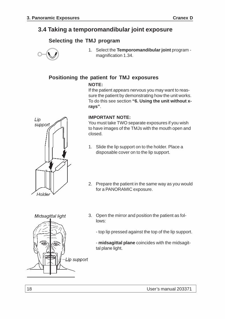
1. Slide the lip support on to the holder. Place adisposable cover on to the lip support.
2. Prepare the patient in the same way as you wouldfor a PANORAMIC exposure.
3. Open the mirror and position the patient as fol-lows:
- top lip pressed against the top of the lip support.
- midsagittal plane coincides with the midsagit-tal plane light.

Cranex D 3. Panoramic Exposures
User’s manual 203371 19
- focal trough light in the same position as forpanoramic exposures, between the upper 2ndtooth (lateral incisor) and the 3rd tooth (canine).
- frankfort plane coincides or is parallel with thehorizontal light.
4. Close the temple supports by moving the templesupport knob to the right, and carefully push theforehead support in until it touches the patient’sforehead or nasion.
5. Close the mirror.
Taking TMJ exposures1. Check once more that the patient has not moved
and is positioned correctly for a TMJ exposure.
2. Press the RETURN key to drive the rotating unit tothe START position.
20 User’s manual 203371
3. Panoramic Exposures Cranex D
Make sure that the READY light is on. If it is notrefer to section 10.1 Error messages.
The kV value, based upon the size of the patient’shead, will be automatically selected.
IMPORTANT NOTE:The rotating unit must be in the STARTposition (press the RETURN key) for the kVvalue to be automatically selected.If the rotating unit is not driven to the STARTposition the kV value will NOT be automaticallyselected and the kV value that was used for theprevious exposure will be selected.
3. If you wish to change the kV, select a differentvalue.
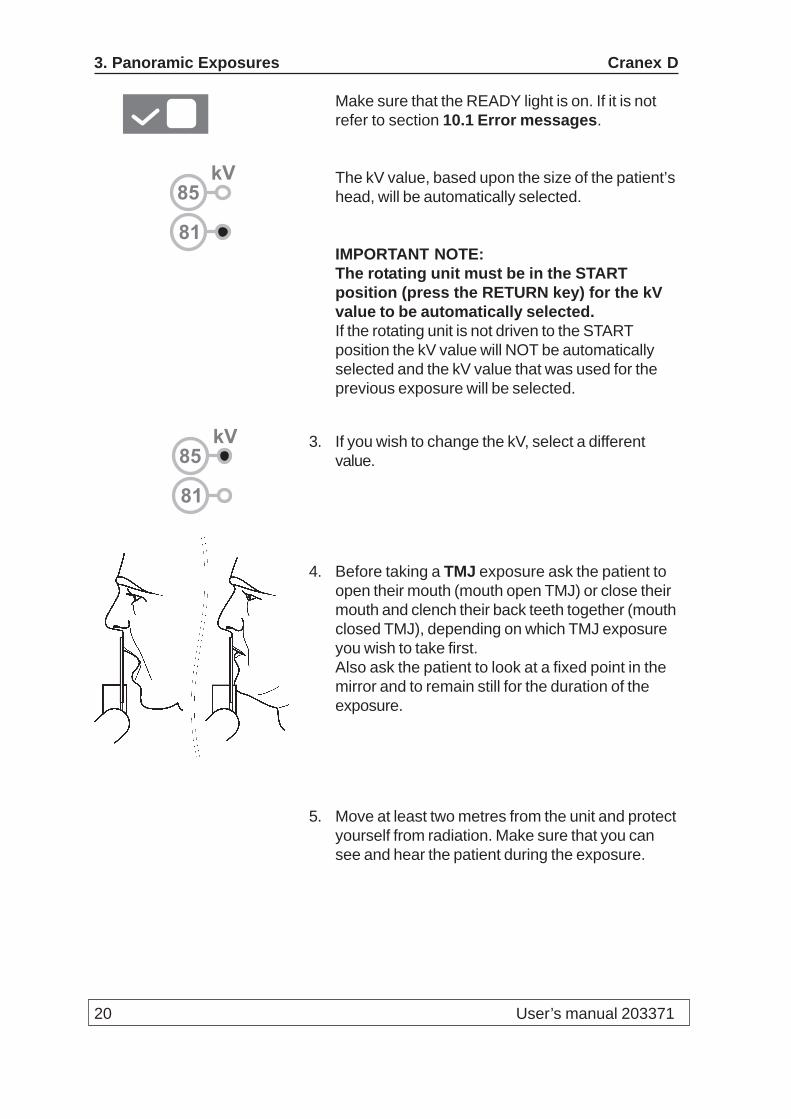
4. Before taking a TMJ exposure ask the patient toopen their mouth (mouth open TMJ) or close theirmouth and clench their back teeth together (mouthclosed TMJ), depending on which TMJ exposureyou wish to take first.Also ask the patient to look at a fixed point in themirror and to remain still for the duration of theexposure.
5. Move at least two metres from the unit and protectyourself from radiation. Make sure that you cansee and hear the patient during the exposure.
81
kV85
81
kV85
Cranex D 3. Panoramic Exposures
User’s manual 203371 21
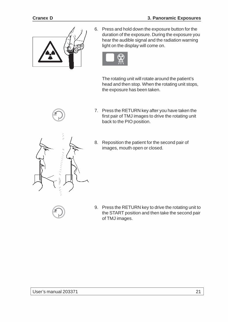
6. Press and hold down the exposure button for theduration of the exposure. During the exposure youhear the audible signal and the radiation warninglight on the display will come on.
The rotating unit will rotate around the patient’shead and then stop. When the rotating unit stops,the exposure has been taken.
7. Press the RETURN key after you have taken thefirst pair of TMJ images to drive the rotating unitback to the PIO position.
8. Reposition the patient for the second pair ofimages, mouth open or closed.
9. Press the RETURN key to drive the rotating unit tothe START position and then take the second pairof TMJ images.
22 User’s manual 203371
3. Panoramic Exposures Cranex D
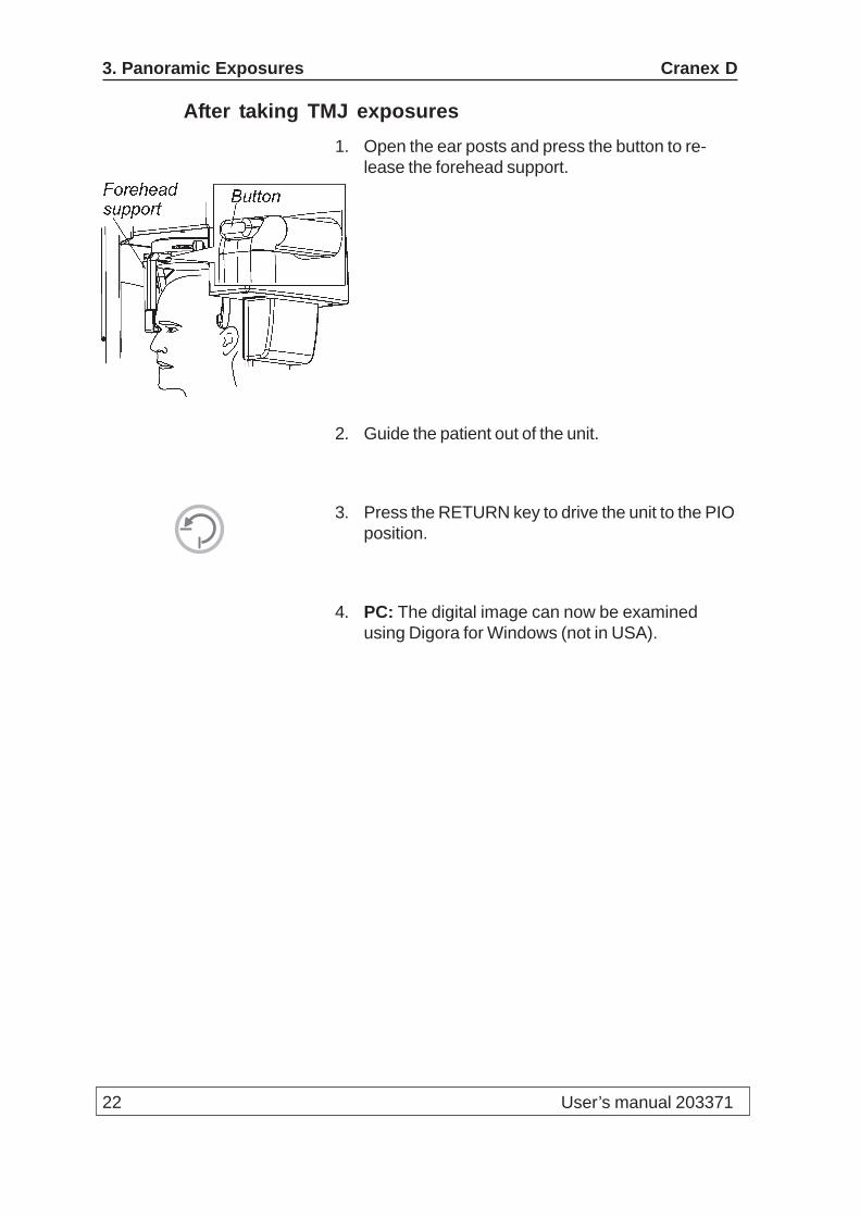
After taking TMJ exposures1. Open the ear posts and press the button to re-
lease the forehead support.
2. Guide the patient out of the unit.
3. Press the RETURN key to drive the unit to the PIOposition.
4. PC: The digital image can now be examinedusing Digora for Windows (not in USA).

Cranex D 3. Panoramic Exposures
User’s manual 203371 23
3.5 Taking a sinus exposure
Selecting the sinus program1. Select the exposure time you require.
Press the S+ key for the fast exposure time or theS- key for the standard exposure time.The selected exposure time will appear on theexposure values display.
NOTE:When the unit is in the PIO position the exposuretime will only appear briefly on the display whenan S key is pressed.
2. Select the Adult panoramic program. All the partialexposure indicator lights will come on.Select the lower three areas.After you select the first area the other indicatorlights will go out. Select the other two areas.The magnification is 1.34.
Exposure times;standard, 15.6 sfast 9.8 s
Positioning the patient for a Sinus exposureNOTE:If the patient appears nervous you may want to reas-sure the patient by demonstrating how the unit works.To do this see section “6. Using the unit without x-rays”.
1. Slide the lip support on to the holder. Place adisposable cover on to the lip support.
S+
S-
24 User’s manual 203371
3. Panoramic Exposures Cranex D
2. Prepare the patient in the same way as you wouldfor a PANORAMIC exposure.
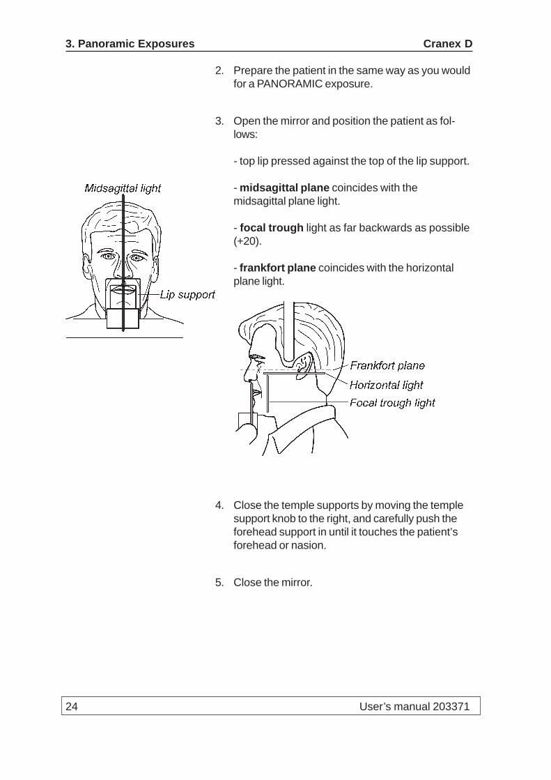
3. Open the mirror and position the patient as fol-lows:
- top lip pressed against the top of the lip support.
- midsagittal plane coincides with themidsagittal plane light.
- focal trough light as far backwards as possible(+20).
- frankfort plane coincides with the horizontalplane light.
4. Close the temple supports by moving the templesupport knob to the right, and carefully push theforehead support in until it touches the patient’sforehead or nasion.
5. Close the mirror.

Cranex D 3. Panoramic Exposures
User’s manual 203371 25
Taking a Sinus exposure1. Check once more that the patient has not moved
and is positioned correctly for a Sinus exposure.
2. Press the RETURN key to drive the rotating unit tothe START position.
Make sure that the READY light is on. If it is notrefer to section 10.1 Error messages.
The kV value, based upon the size of the patient’shead, will be automatically selected.
IMPORTANT NOTE:The rotating unit must be in the STARTposition (press the RETURN key) for the kVvalue to be automatically selected.If the rotating unit is not driven to the STARTposition the kV value will NOT be automaticallyselected and the kV value that was used for theprevious exposure will be selected.
3. If you wish to change the kV, select a differentvalue.
81
kV85
81
kV85

26 User’s manual 203371
3. Panoramic Exposures Cranex D
4. Before taking a Sinus exposure ask the patient topress their lips together.Also ask the patient to look at a fixed point in themirror and to remain still for the duration of theexposure.
5. Move at least two metres from the unit and protectyourself from radiation. Make sure that you cansee and hear the patient during the exposure.
6. Press and hold down the exposure button for theduration of the exposure. During the exposure youhear the audible signal and the radiation warninglight on the display will come on.
The rotating unit will rotate around the patient’shead and then stop. When the rotating unit stops,the exposure has been taken.
After taking a Sinus exposure1. Open the temple supports and press the button to
release the forehead support.
2. Guide the patient out of the unit.
3. Press the RETURN key to drive the unit to the PIOposition.
4. PC: The digital image can now be examinedusing Digora for Windows (not in USA).
Cranex D 4. Cephalometric exposures
User’s manual 203371 27
4. Taking cephalometric exposures (Ceph option)
4.1 Preparing the PCPrepare the PC in the same way as described inTaking panoramic exposures.
4.2 Preparing the unit1. Attach the CCD sensor to the sensor holder on
the ceph head, see section “7. Attaching andremoving the CCD sensor”.
2. Switch the unit on.
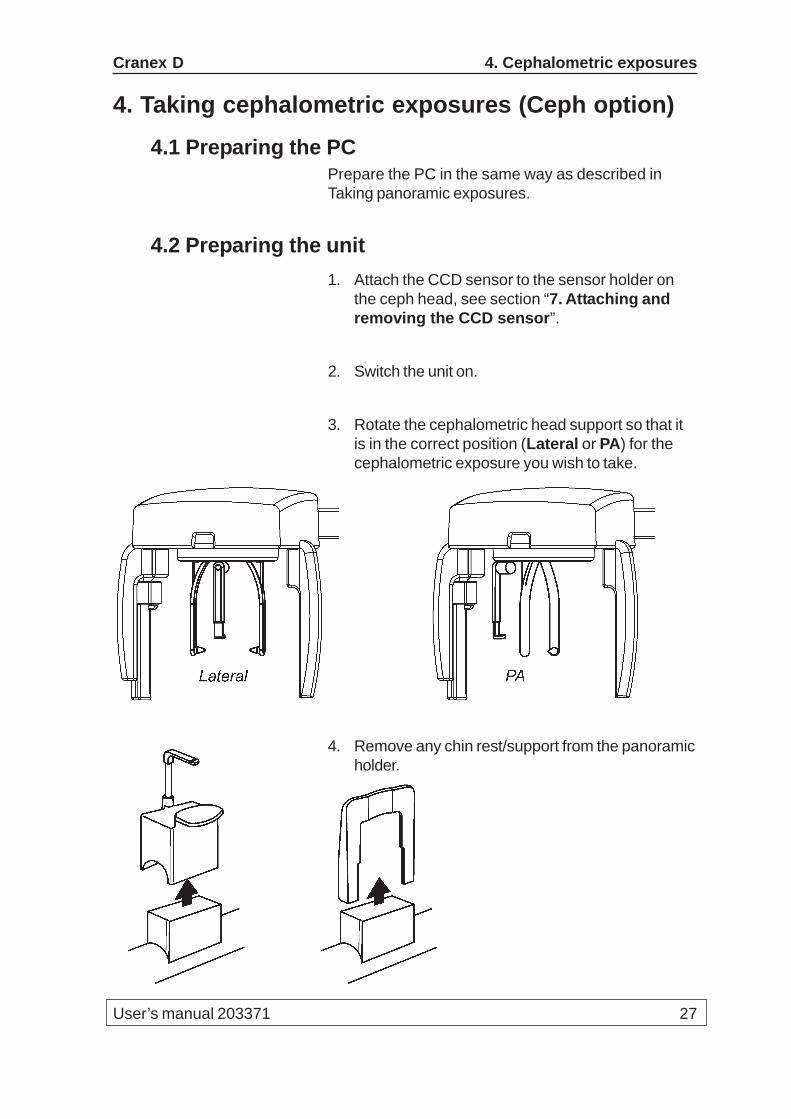
3. Rotate the cephalometric head support so that itis in the correct position (Lateral or PA) for thecephalometric exposure you wish to take.
4. Remove any chin rest/support from the panoramicholder.
28 User’s manual 203371
4. Cephalometric exposures Cranex D
4.3 Taking a cephalometric exposure
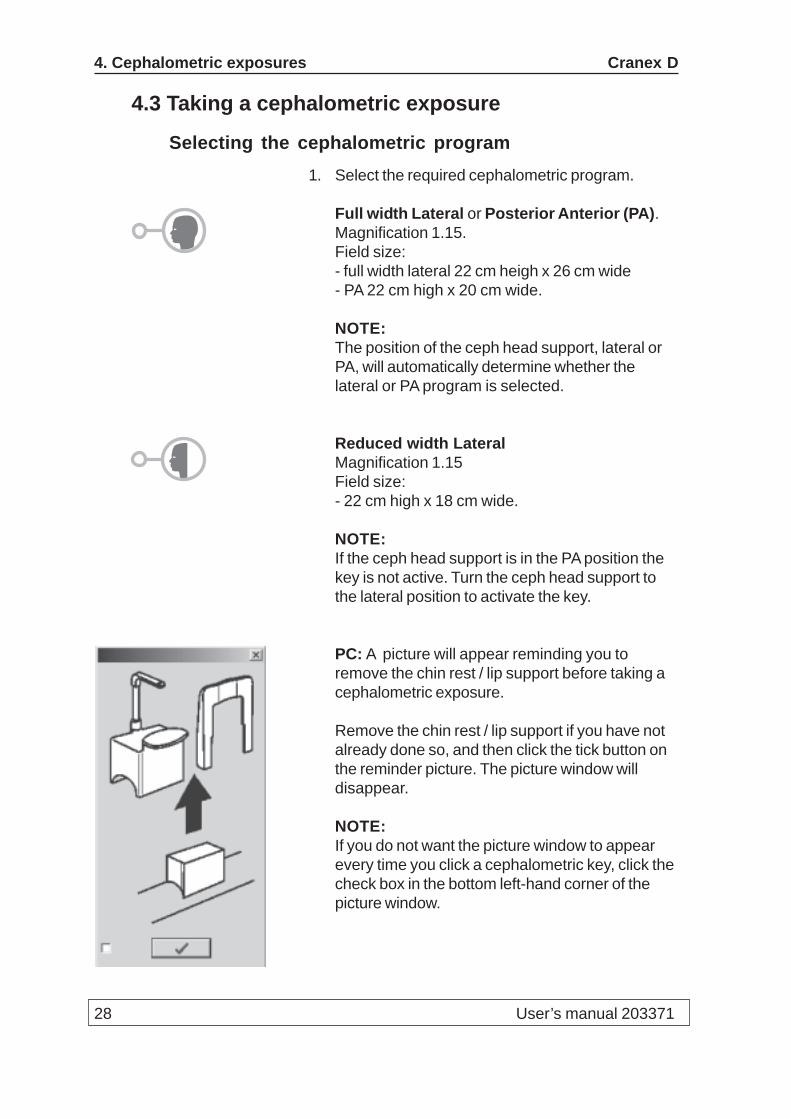
Selecting the cephalometric program1. Select the required cephalometric program.
Full width Lateral or Posterior Anterior (PA).Magnification 1.15.Field size:- full width lateral 22 cm heigh x 26 cm wide- PA 22 cm high x 20 cm wide.
NOTE:The position of the ceph head support, lateral orPA, will automatically determine whether thelateral or PA program is selected.
Reduced width LateralMagnification 1.15Field size:- 22 cm high x 18 cm wide.
NOTE:If the ceph head support is in the PA position thekey is not active. Turn the ceph head support tothe lateral position to activate the key.
PC: A picture will appear reminding you toremove the chin rest / lip support before taking acephalometric exposure.
Remove the chin rest / lip support if you have notalready done so, and then click the tick button onthe reminder picture. The picture window willdisappear.
NOTE:If you do not want the picture window to appearevery time you click a cephalometric key, click thecheck box in the bottom left-hand corner of thepicture window.

Cranex D 4. Cephalometric exposures
User’s manual 203371 29
Positioning the patient1. Press the RETURN key to drive the rotating unit to
the ceph PIO position. The CCD sensor will alsomove to the PIO position.
2. Place the protective disposable covers onto theear cones.

30 User’s manual 203371
4. Cephalometric exposures Cranex D
3. Ask the patient to stand between the open earposts. Adjust the height of the unit so that the earposts are level with the patients ears.Position patient’s head so that the Frankfort planeis horizontal.
4. Close the ear posts by sliding the ear post knobto the left.
WARNINGNEVER move the unit up or down when the earposts are in the patient’s ears.
5. If you are taking a lateral exposure push thefrontal support in carefully until it touches thepatient’s nasion.The frontal support will automatically select thecorrect amount of soft tissue filtering.If you are taking a PA exposure turn the frontalsupport sideways to the horizontal position.
Cranex D 4. Cephalometric exposures
User’s manual 203371 31
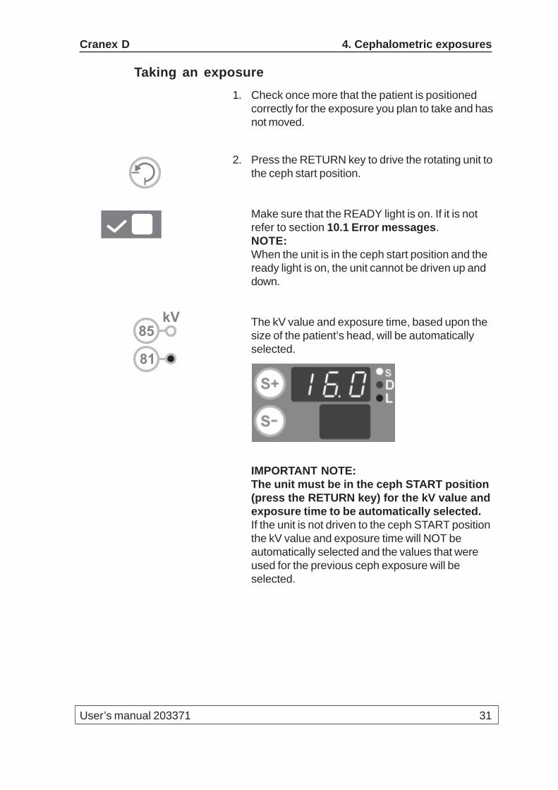
Taking an exposure1. Check once more that the patient is positioned
correctly for the exposure you plan to take and hasnot moved.
2. Press the RETURN key to drive the rotating unit tothe ceph start position.
Make sure that the READY light is on. If it is notrefer to section 10.1 Error messages.NOTE:When the unit is in the ceph start position and theready light is on, the unit cannot be driven up anddown.
The kV value and exposure time, based upon thesize of the patient’s head, will be automaticallyselected.
IMPORTANT NOTE:The unit must be in the ceph START position(press the RETURN key) for the kV value andexposure time to be automatically selected.If the unit is not driven to the ceph START positionthe kV value and exposure time will NOT beautomatically selected and the values that wereused for the previous ceph exposure will beselected.
81
kV85

32 User’s manual 203371
4. Cephalometric exposures Cranex D
3. If you wish to change the kV or exposure time,select different values.
4. Ask the patient to bite their teeth together nor-mally.
5. Move at least two metres from the unit and protectyourself from radiation. Make sure that you cansee the patient during the exposure.
6. Press and hold down the exposure button for theduration of the exposure. During the exposure youhear the audible signal and the radiation warninglight on the display.
81
kV85
Cranex D 4. Cephalometric exposures
User’s manual 203371 33
After exposure1. Open the ear posts and the forehead support.
2. Guide the patient out of the unit. The front headsupport can be turned to make it easier for thepatient to get out.
3. PC: The digital image can now be examinedusing Digora for Windows (not in USA).
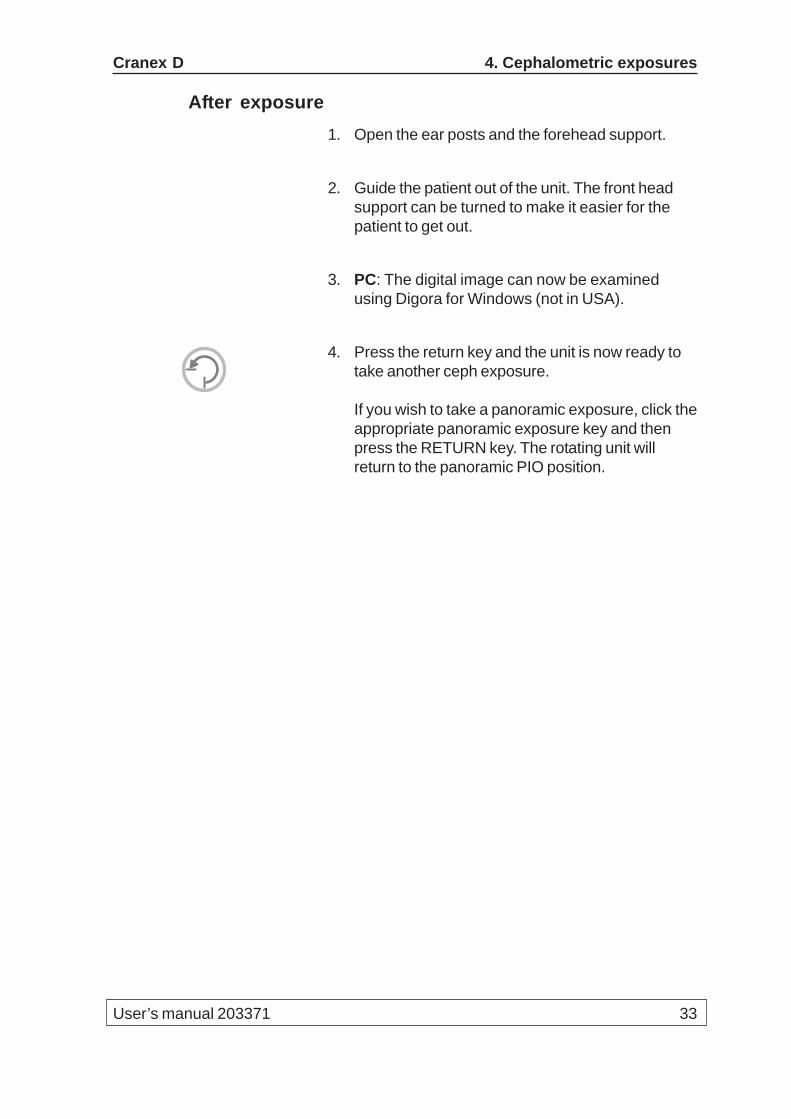
4. Press the return key and the unit is now ready totake another ceph exposure.
If you wish to take a panoramic exposure, click theappropriate panoramic exposure key and thenpress the RETURN key. The rotating unit willreturn to the panoramic PIO position.

34 User’s manual 203371
5. Carpus exposures Cranex D
5. Carpus exposures (Not in USA)1. Prepare the unit to take a PA cephalometric
exposure.
2. Slide the carpus holder on to the forehead supportand then lock the carpus holder in position byturning the locking knob.
3. Press the RETURN key to drive the rotating unit tothe ceph start position.
Check that the READY light is on. If it is not referto section 10.1 Error messages.
Cranex D 5. Carpus exposures
User’s manual 203371 35
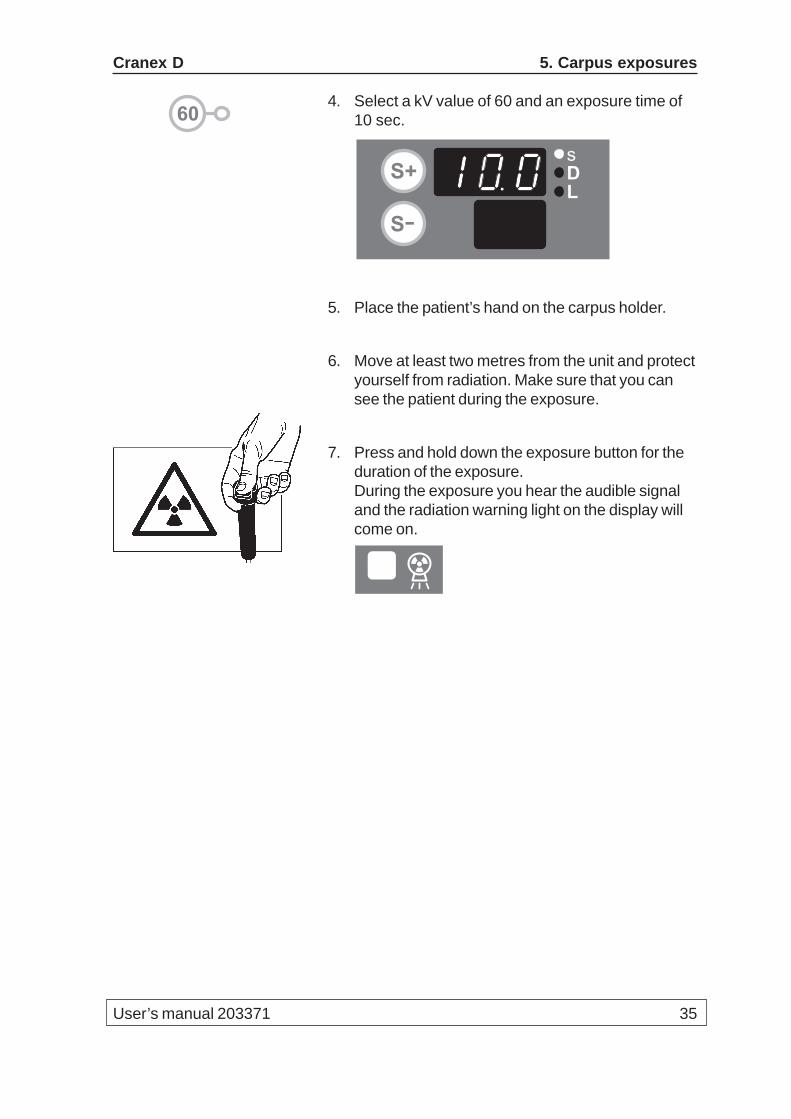
4. Select a kV value of 60 and an exposure time of10 sec.
5. Place the patient’s hand on the carpus holder.
6. Move at least two metres from the unit and protectyourself from radiation. Make sure that you cansee the patient during the exposure.
7. Press and hold down the exposure button for theduration of the exposure.During the exposure you hear the audible signaland the radiation warning light on the display willcome on.
60
DL
S+
S-
s
36 User’s manual 203371
6. Using the unit without x-rays Cranex D
6. Using the unit without x-raysIn some situations, for example with nervous patientsor patients with unusual anatomy, you may wish tooperate the unit without x-rays before taking a properexposure.
To do this, press the TEST (T) key, the indicator lightwill come on. The exposure switch can now bepressed to demonstrate how the unit operates withoutx-rays being generated.
Press the TEST (T) key a second time to return to thenormal exposure mode.
T
Cranex D 7. Attaching and removing the CCD sensor
User’s manual 203371 37
7. Attaching and removing the CCD sensorIMPORTANT NOTE:Handle the CCD sensor with care and do not drop it.
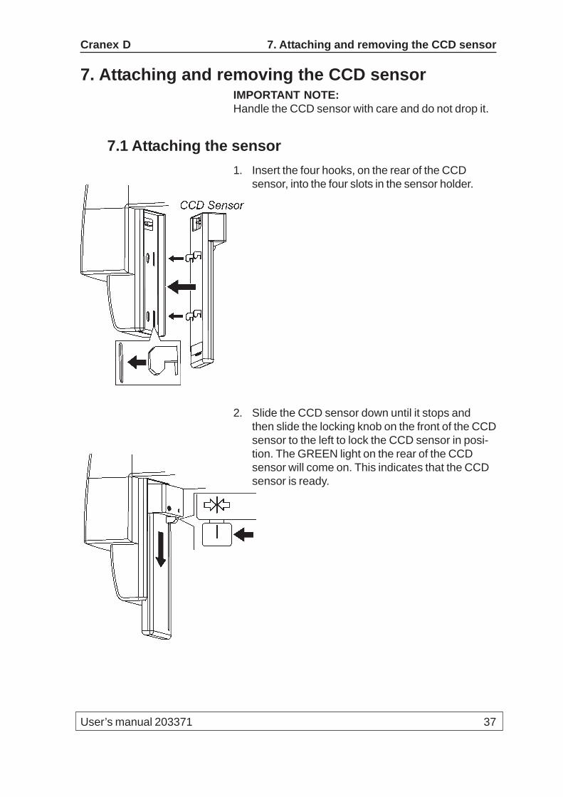
7.1 Attaching the sensor1. Insert the four hooks, on the rear of the CCD
sensor, into the four slots in the sensor holder.
2. Slide the CCD sensor down until it stops andthen slide the locking knob on the front of the CCDsensor to the left to lock the CCD sensor in posi-tion. The GREEN light on the rear of the CCDsensor will come on. This indicates that the CCDsensor is ready.
38 User’s manual 203371
7. Attaching and removing the CCD sensor Cranex D
NOTE:If the light is RED it indicates that the CCD sensoris not functioning correctly. Switch the unit off andthen on again. If the light is still RED, contact youdealer for assistance.
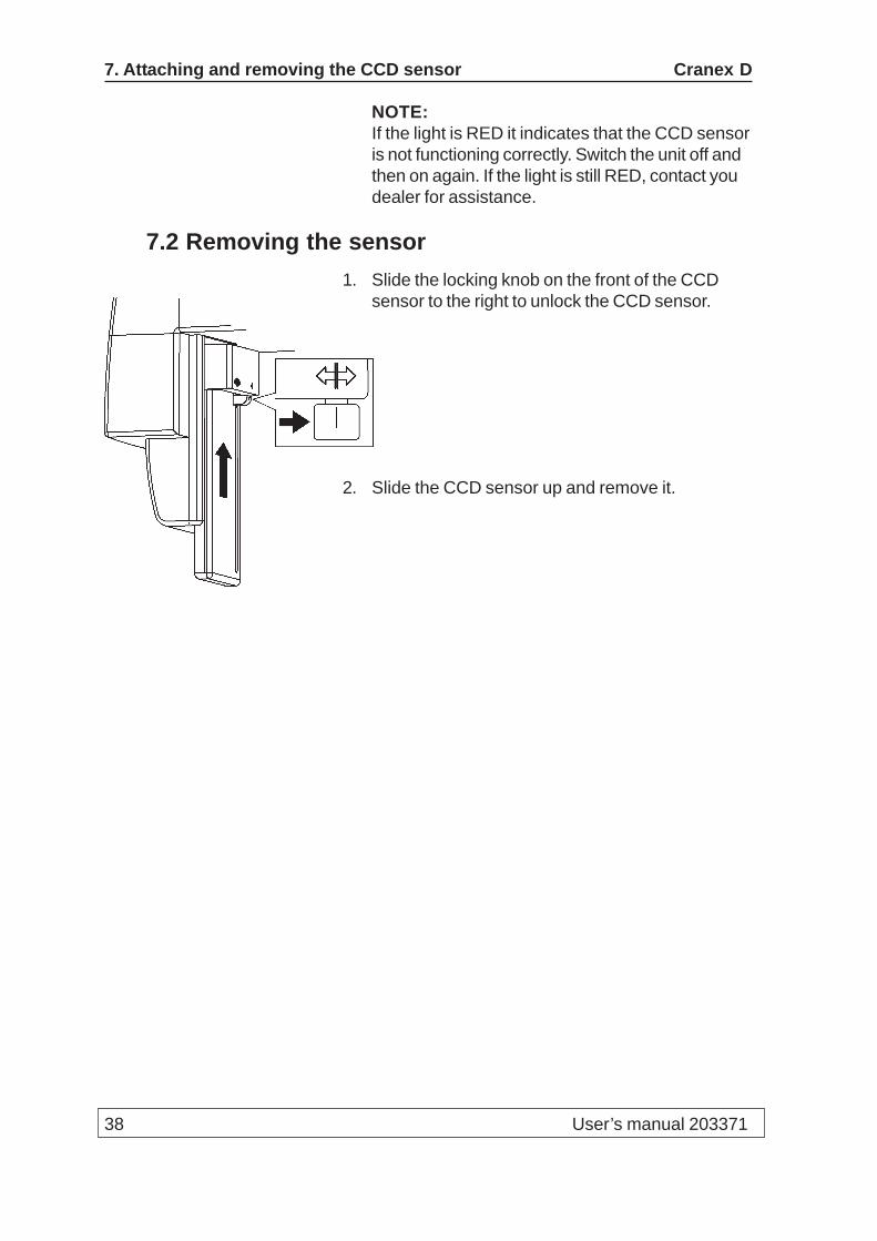
7.2 Removing the sensor1. Slide the locking knob on the front of the CCD
sensor to the right to unlock the CCD sensor.
2. Slide the CCD sensor up and remove it.

Cranex D 8. Exposure switch lock
User’s manual 203371 39
8. Exposure switch lockThe exposure switch lock allows the exposure switchto be locked. This prevents unauthorized people fromtaking exposures even if the unit is switched on. Theexposure switch lock is located on the side of the unit.
8.1 Unlocking the exposure switchInsert the key and turn it clockwise to the horizontalposition to unlock the exposure switch.
8.2 Locking the exposure switchTurn the key anticlockwise to the vertical position andremove the key. The exposure switch is locked.
40 User’s manual 203371
9. Unit setup Cranex D
9. Unit setupVarious setup options allow the unit to be customizedto your specific requirements
9.1 Setup options1. PC: Open DfW (not in the USA) or the dental
imaging software you are using.
2. PC: Select Options and then click CRANEX DSetup.The CRANEX D Setup window will appear.
The Device Status fieldShows the statuses of the Pan device or Cephdevice (Pan/Ceph) device.The statuses are:- Ok, the device is ready for image capture- Connected, the device is connected to the PC.- Disconnected, the unit is switched off or thethere is no connection between the unit and thePC.- No Camera, the CCD sensor is not connectedto the unit.- Not Enabled, device not enabled.- Not Enabled (no gain file), device not enabledbecause the gain file is missing.
The Versions fieldShows the software and driver versions.
The Image Processing fieldThe Show image preview check box, seesection 9.2 Image Preview.
The Automatic Density Adjust check box.Select to automatically optimize the imagedensity.

Cranex D 9. Unit setup
User’s manual 203371 41
The Apply Enhancement check box.Select to sharpen the image. The enhancementvalue must be entered in the Matrix size edit box.The recommended value is between 7 and 11.The maximum value is 25 (maximum sharpening)and 1 is the minimum (minimum sharpening).
The Retrieve Last Image fieldIf you wish to recover an image after a systemfailure or are dissatisfied with any automatic ormanual changes made to the the image, click theMust be ......... retrieved check box to retrieve theoriginal image.
The Device Serial Number fieldThe Add serial number ... check box. Select, andthen enter the serial number of the unit into theSerial number edit box to add the serial to theimages. The serial number will appear in the topleft-hand corner and the bottom right-hand cornerof all new images.
NOTE:If you select Enable image marking in DFW(General Setup / Image / Image marking) doNOT select the left top or right bottom options asthe image marking text will appear on top of theserial number.
42 User’s manual 203371
9. Unit setup Cranex D
9.2 Image PreviewThe Image Preview feature allows an image to beadjusted BEFORE it is saved. The adjustments beapplied to the open image only or to ALL subsequentimages.
CAUTION:Adjustments made to images CANNOT be undoneafter the adjustments have been saved. If you wish to“undo” the adjustments retrieve the original imageclick Retrieve Last Image.
1. PC: In the CRANEX D Setup window click theShow Image Preview check box.
2. Take an exposure.
3. PC: The Image Preview window willautomatically appear.To activate image adjustment, click the DensityAdjustment and Sharpen filter check boxes.The Image Quality Controls will become activeand the image can be adjusted.
CURRENT IMAGE ONLYClick OK to apply the adjustments to the image inthe Image Preview window ONLY.
CURRENT AND ALL SUBSEQUENT IMAGESClick the Edit Quality Presets button.The Set Image Quality Presets window willappear. The Get from Preview window radiobutton will be active. Click OK to accept theimage adjustments you have made.The Image Preview window will reappear. ClickOK to apply adjustments to the current image andALL subsequent images.
NOTE:If you wish to have the factory default settingsclick the Factory defaults radio button.
Cranex D 9. Unit setup
User’s manual 203371 43
The Marking fieldThese tools allow you to add text and numbers toan image.
44 User’s manual 203371
10. Troubleshooting and maintenance Cranex D
10. Troubleshooting and maintenance10.1 Error messages
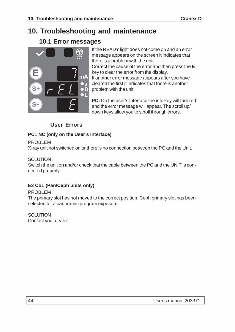
If the READY light does not come on and an errormessage appears on the screen it indicates thatthere is a problem with the unit.Correct the cause of the error and then press the Ekey to clear the error from the display.If another error message appears after you havecleared the first it indicates that there is anotherproblem with the unit.
PC: On the user’s interface the info key will turn redand the error message will appear. The scroll up/down keys allow you to scroll through errors.
User ErrorsPC1 NC (only on the User’s Interface)PROBLEMX-ray unit not switched on or there is no connection between the PC and the Unit.
SOLUTIONSwitch the unit on and/or check that the cable between the PC and the UNIT is con-nected properly.
E3 CoL (Pan/Ceph units only)PROBLEMThe primary slot has not moved to the correct position. Ceph primary slot has beenselected for a panoramic program exposure.
SOLUTIONContact your dealer.
mA
DL
E
S+
S-
s

User’s manual 203371 45
Cranex D 10. Troubleshooting and Maintenance
E4 CoL (Pan/Ceph units only)PROBLEMThe primary slot has not moved to the correct position. Panoramic primary slot hasbeen selected for a ceph exposure.
SOLUTIONContact your dealer.
E7 rELPROBLEMThe exposure button was released during an exposure.
SOLUTIONCheck if the attempted exposure is sufficient for the diagnostic task. If it is not, take anew exposure.If the exposure failed while the exposure button was still being pressed, check theexposure switch by taking a test exposure without patient to see if the exposurebutton is defective or not. If the same problem occurs again, call service.
E8 MoEPROBLEMThe exposure button was pressed when one of the Y/Z keys was being pressed.
SOLUTIONDo not press the exposure button while the Y/Z buttons are being pressed.
E9 (***) (the WAIT time will appear in seconds)PROBLEMThe WAIT time (cooling time between exposures) has not yet elapsed.
SOLUTIONWait until the WAIT time elapses.
46 User’s manual 203371
10. Troubleshooting and maintenance Cranex D
E10 dorPROBLEMThe patient positioning mirror is open.
SOLUTIONClose the mirror.
E12 cCoPROBLEMThe primary collimator has not changed to the child panoramic size.
SOLUTIONPress the E key to clear the error message. Then press the RETURN key to drive theunit to the PIO position, and then press the key again to drive it to the START posi-tion. If the error message reappears, call service.
E16 PoSPROBLEMi. The rotating unit is not in the PIO or START position.
ii The mirror is open.
SOLUTIONi. Press the E key to clear the error and then press the RETURN key to drive therotating unit to the right position.
ii. Close the mirror.
E18 dChPROBLEM
i. There is no connection to the PC
ii. or DfW (not in USA), or the dental imaging software you are using is not open
iii. or the CCD sensor is not attached to the sensor holder
iv. or the CCD sensor is attached to the wrong sensor holder (pan/ceph units only)
v. or the CCD sensor is not fully locked in position

User’s manual 203371 47
Cranex D 10. Troubleshooting and Maintenance
SOLUTION
i. Switch the PC on and start DfW (not in USA), or the dental imaging software youare using and start the User Interface program
ii. Start DfW (not in USA) or the dental imaging software you are using.
iii. Attach the CCD sensor to the sensor holder.
iv. Attach the CCD sensor to the correct pan or ceph sensor holder.
v. Make sure that the CCD sensor locking lever is pushed fully to the left, the lockedposition.
Unit ErrorsIf any of the following errors appear, switch the unit offand then on again. If the error message reappearscall service for help.
C1 HHoPROBLEMThe thermal switch in the tubehead has been activated because the unit has overheated because of extended continuous use.
SOLUTIONWait at least one hour for the tubehead to cool down. Note that you will not be able toclear the error message until the tube head has cooled to the correct temperature. Ifthe error message appears even if the unit has not been used a lot, switch the unit offand then on again. If the error message reappears call service for help.
C2 (***) (the mains voltage is displayed)The mains voltage out of allowed tolerances.
C3 gEnTube fail signal activated. Tubehead or generator defected.
C4 InuInverter defect. The voltage of the tube does not increase during an exposure.
C5 FILFilament defect. mA does not increase during exposure.
C6 EEPEEPROM defect.
48 User’s manual 203371
10. Troubleshooting and maintenance Cranex D
C7 PorR movement error.
C8 PoCCollimator movement error.
C9 PoLLinear (Y) movement error.
C10 PoUZ movement error.
C11 PocCephalo movement error.
C12 SEnCCD sensor base frequency failing.
C13 (***) (the wait time will appear in seconds)Stepping motors over heated.
C14 CbaCephalo beam misaligned.
C15nPCNo connection to PC or PC does not acknowledge the image identification data.SOLUTION: Check that the cables between the PC and unit are connected.
C19LbLThe PC acknowledges the image identification data, but the data is corrupted.SOLUTION: Check that the cables between the PC and unit are connected.
C40 rAMRAM defect.
C41 roMEPROM defect.
C42 LinMains voltage selector in wrong position.
C43 FILPreheat circuit not functioning/preheat not calibrated on the Filament Board.
C44 InPA key is held or stuck down
User’s manual 203371 49
Cranex D 10. Troubleshooting and Maintenance
C46 cPuCPU defect.
C51 UIb (Only PC user’s interface)X-ray unit is in the “service” mode. Reset error codes from control panel.
Other operating problems
The unit does not become READY for an exposure.CAUSEWrong collimator, CCD sensor not installed or no connection to the PC.
SOLUTIONPress the exposure or info button. On the kV and mA displays there appears an errorcode, which indicates the reason, why the unit is not ready for exposure. Clear theerror code by pressing the E key. Rectify the reason. If the error appears, although thedetail is in order, please call service.
The unit does not move to the start position (START).CAUSEThe unit is not ready for exposure (READY).
SOLUTIONFind out why the unit is not ready for exposure by pressing the exposure button. Rec-tify the problem and try again.
Red error Indicator light on the CCD sensor comes on.CAUSEIf the GREEN led on the rear of the CCD sensor turns RED, it indicates that there is aproblem with the CCD sensor imaging chain.
SOLUTIONSwitch the power off from the Cranex D unit for few seconds and switch it on again.

50 User’s manual 203371
10. Troubleshooting and maintenance Cranex D
10.2 Care and MaintenanceCleaning and disinfecting the unit
WarningSwitch the unit off before cleaning it.
Enamelled surfacesAll enamelled surfaces can be wiped clean with a softcloth dampened with a mild detergent. NEVER useabrasive cleaning agents or polishes on this equip-ment.
Positioning mirror and light lensesThe positioning mirror and positioning light lenses aremade of glass. Use a soft cloth dampened with a milddetergent. NEVER use abrasive cleaning agents orpolishes on this equipment.
Surfaces that the patient touchesAll surfaces and parts that the patient touches orcomes into contact with must be disinfected aftereach patient. Use a disinfectant that is formulatedspecifically for disinfecting dental equipment and usethe disinfectant in accordance with the manufacturer’sinstructions.
Correct operation of the unitIf any of the unit’s controls, displays or functions fail tooperate or do not operate in the way described in thismanual, switch the unit off, wait 30 seconds and thenswitch the unit on again. If the unit still does not oper-ate correctly contact your service technician for help.
If you hear the exposure warning tone but the expo-sure warning light does not come on when an expo-sure is taken, stop using the unit and contact yourservice technician for help.
User’s manual 203371 51
Cranex D 10. Troubleshooting and Maintenance
If you do not hear the exposure warning tone when anexposure is taken, stop using the unit and contactyour service technician for help.
Check weekly that the mains cable of the unit is inproper order and that all the unit operates. Make surethat the unit does not move up/down if the safetyswitch is pressed.
Yearly maintenanceOnce a year an authorized service technician mustcarry out a full inspection of the unit. During theinspection the following tests will be carried out:– a kV/mA test– a beam alignment test– a ball/pin test– a check to see that the safety ground is connected– a check to see that the positioning lights operate– a check to see that the tube head is not leaking– a check to see that all covers and mechanicalparts are correctly secured and have not comeloose.A full description of all the tests and checks is de-scribed in the Service Manual.
DisposalAt the end of the useful working life of the unit and / orits accessories make sure that you follow national andlocal regulations regarding the disposal of the unit, itsaccessories, parts and materials. The unit includessome parts that are made of or include materials thatare non-environmentally friendly or hazardous.
52 User’s manual 203371
11. Warnings and precautions Cranex D
11. Warnings and precautions• The unit must only be used to take the dental x-ray
exposures described in this manual. The unit mustNOT be used to take any other x-ray exposures.It is not safe to use the unit to take an x-ray expo-sure that the unit is not designed to take.
• The unit or its parts must not be changed or modi-fied in any way without approval and instructionsfrom Soredex.
• The unit may be dangerous to the user and thepatient, if the safety regulations in this manual areignored, if the unit is not used in the way de-scribed in this manual and/or if the user does notknow how to use the unit.
• Always use the lowest suitable x-ray dose toobtain the desired level of image quality.
• Because the x-ray limitations and safety regula-tions change from time to time, it is the responsi-bility of the user to make sure that all the validsafety regulations are fulfilled.
• It is the responsibility of the doctor to decide if thex-ray exposure is necessary.
• Avoid taking x-ray exposures of pregnant women.
• Never press the up/down height adjustment button(Z-movement) when the patient is positioned inthe cephalometric head holder.

User’s manual 203371 53
Cranex D 11. Warnings and precautions
• The user must protect him/herself from radiationwhen taking exposures. The user must stand atleast two meters from the patient when takingexposures.
• The user must be able to see and hear the patientat all times.
• The user must see the radiation warning light andhear the audio warning signal during the expo-sure. If the unit is installed in such a place wherethe warning light cannot be seen, a separatewarning light must be used. Please contact thelocal service for help.
• If the unit does not appear to be working correctly,switch the unit off and release the patient. Makesure that the unit operates correctly before youcontinue using it. If you are not sure whether theunit is operating correctly, please contact the localservice.
• If the unit will not be used for a long time, switchthe unit off and lock the key switch, in order toprevent unauthorized exposures.
• Disinfect all the surface that the patient has con-tact with after every patient.
• If this device will be used with 3rd party imagingapplication software not supplied by SOREDEX,the 3rd party imaging application software mustcomply with all local laws on patient informationsoftware. This includes, for example, the MedicalDevice Directive 93/42/EEC and/or FDA if appli-cable.
54 User’s manual 203371
11. Warnings and precautions Cranex D
A - 1
Cranex D (Version 3) Appendix A - Technical Information
Appendix A - Technical InformationA.1 Technical specifications
ModelPP1
ClassificationIEC class I, type B, IP20Conforms with the standards EN 60601-1, EN60601-1-3, EN 60601-2-7 and EN60601-1-2 (Group 1, class B)
Conforms with the regulations of DHHS Radiation Performance Standard, 21CFRSubchapter J.
The unit must be installed within a protected clinical area.
Unit descriptionDental panoramic and panoramic/cephalometric x-ray units with a high frequencyswitching mode x-ray generator. The panoramic version takes panoramic exposures.The panoramic/cephalometric version takes panoramic and cephalometricexposures. The unit uses a CCD sensor as image receptor.
X-ray generatorTUBE
- OPX/105, or equivalentFOCAL SPOT
- 0.5 mm IEC 336TARGET ANGLE
- 5ºTARGET MATERIAL
- TungstenOPERATING TUBE POTENTIAL
- Panoramic imaging 57 - 85 kV (±4 kV)- Cephalometric imaging 60 - 85 kV (±4 kV)
OPERATING TUBE CURRENT- 10 mA (±1 mA) at 0.5 FS
MAXIMUM TUBE CURRENT- 11 mA
MAXIMUM OUTPUT POWER- 945 W nominal
FILTRATION- minimum filtration 2.7 mm Al
A - 2
Appendix A - Technical Information Cranex D (Version 3)
BEAM QUALITY- HVL over 2.5 mm Al @ 85 kV
OUTER SHELL TEMPERATURE- +50ºC (122ºF) maximum
DUTY CYCLE- controlled by the software of the unit
Power requirementsINPUT VOLTAGE
- 230 or 115 VAC (±10%), 50/60 Hz, single phase, grounded socketMAXIMUM LINE CURRENT
- 7 A (@85 kV/10mA, 230 VAC mains)MAXIMUM LINE RESISTANCE
- 1 ohmMAXIMUM LINE FUSING
- 10 A /20A slow @ 230/115 VAC (main fuse 8A/16A slow in the device)LINE SAFETY SWITCH (when required)
- Approved type, min. 10 A 250 VACEARTH LEAKAGE CIRCUIT BREAKER (when required)
- Approved type, min. 16 A 250 VAC, breaker activation leakage current inaccordance with local regulations.
Mechanical parametersPANORAMIC
- Source to Image layer Distance (SID) 520 mm (±10 mm)- Magnification factor 1.34
CEPHALOMETRIC- Source to Image layer Distance (SID) 1721 mm ±20 mm- Source to Object Distance (SOD) 1500mm-Magnification factor 1.15
WEIGHT- Panoramic unit 120 kg- Panoramic/cepahlometric unit 165 kg
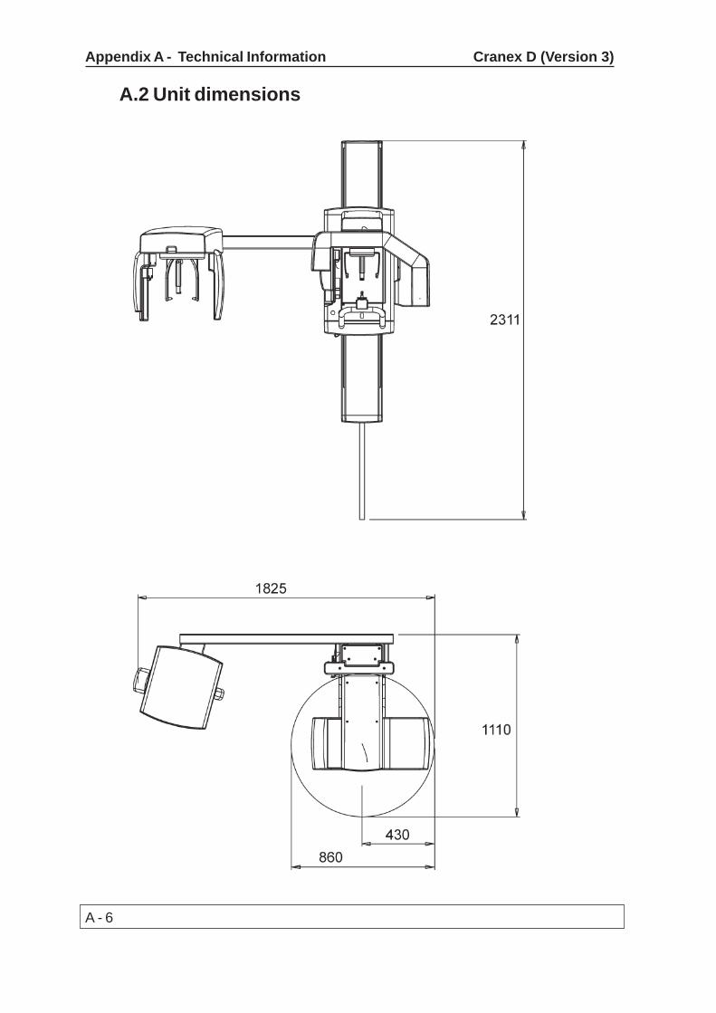
DIMENSIONS- Panoramic unit (H x W x D) 2320 x 1200 x 1000 mm- Panoramic/cephalometric unit (H x W x D) 2320 x 1200 x 1900 mm
VERTICAL HEIGHT OF CHIN REST- 950 - 1750 mm (+- 10 mm)
A - 3
Cranex D (Version 3) Appendix A - Technical Information
Digital image receptorOnly the CCD sensors specifically designed for Cranex D unit can be used.PIXEL SIZE
- 96 micrometres
TimerPANORAMIC EXPOSURE TIMES
- Adult normal 17.6 s (±15%), fast 11 s (±15%)- Child normal 13.8 s (±15%), fast 8.6 s (±15%)- Partial normal 3.1 s - 4 s - 7.6 s - 4 s - 3.1 s,
fast 1.9 s - 2.5 s - 4.8 s - 2.5 s - 1.9 sCan be freely selected and combined, overlap approx. 0.3 s.
- TMJ 3.2 + 3.2 s (±15%)Max 240 mAs
CEPHALOMETRIC EXPOSURE TIMES- 8 - 20 s scanning times, 5 steps according to R’10 series (ISO)
BACK-UP TIMER- 23.5 s (±1.5s)
Leakage technique factorsPANORAMIC
- 85 kV, 2400 mAs/h (85 kV, 10 mA, duty cycle 1:15)
CEPHALOMETRIC- 85 kV, 1800 mAs/h (85 kV, 10 mA, duty cycle 1:20)
Measurement baseskV and mA values can be verified with a specified digital multimeter according toseparate measurement instructions. The exposure times can be measured as theduration of radiation in the primary radiation beam.
Exposed field size in cephalometry- 22 x 26 cm for lateral projections
- 22 x 20 cm for PA and AP projections- Automatic filtration of soft tissues for lateral projections controlled bysoftware.
Operating ambient conditions- Operating temperature 10 - 40ºC- Relative humidity 0 - 85 RH%

A - 4
Appendix A - Technical Information Cranex D (Version 3)
Storage ambient conditions- Storage temperature 0 - 40ºC- Relative humidity 0 - 85 RH%
Minimum computer requirementsThe values in (brackets) are recommended values.OPERATING SYSTEM
- Windows XP Professional / Home / SP1 or SP2- Windows 2000 Professional / SP4
CPU- Pentium 4 or Athlon XP or equivalent (1.5 GHz or better recommended)
RAM- 256 MB (512 MB recommended)
HDD- 20 GB (single user)
VIDEO RAM- 16 MB (or more)
NETWORK CONNECTION- 10/100 Mbit/s Ethernet NIC
DISPLAY- 1280 x 1024 x 24-bit Tru Color, 85Hz display (19" CRT or 17” TFT LCD recommended)
PCI slot- 1 free
Connection to the PC must meet EN60601-1 requirements.The use of ACCESSORY equipment not complying with the equivalent safety re-quirements of this equipment may lead to a reduced level of safety of the resultingsystem. Consideration relating to the choice shall include:- use of the accessory in the PATIENT VICINITY- evidence that the safety certification of the ACCESSORY has been performed inaccordance to the appropriate IEC 601-1 and/or IEC 601-1-1 harmonized nationalstandard- the fibre optic cable, provided by the manufacturer, shall be used.

A - 5
Cranex D (Version 3) Appendix A - Technical Information
Tube housing assembly cooling characteristics
OPX/105 and KL5
A - 6
Appendix A - Technical Information Cranex D (Version 3)
A.2 Unit dimensions

A - 7
Cranex D (Version 3) Appendix A - Technical Information
A.3 Symbols that appear on the unit
This symbol indicates that the waste of electrical andelectronic equipment must not be disposed asunsorted municipal waste and must be collectedseparately. Please contact an authorizedrepresentative of the manufacturer for informationconcerning the decommissioning of your equipment.
A - 8
Appendix A - Technical Information Cranex D (Version 3)
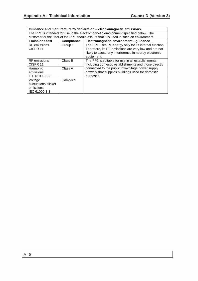
Guidance and manufacturer’s declaration – electromagnetic emissions The PP1 is intended for use in the electromagnetic environment specified below. The customer or the user of the PP1 should assure that it is used in such an environment. Emissions test Compliance Electromagnetic environment - guidance RF emissions CISPR 11
Group 1 The PP1 uses RF energy only for its internal function. Therefore, its RF emissions are very low and are not likely to cause any interference in nearby electronic equipment.
RF emissions CISPR 11
Class B
Harmonic emissions IEC 61000-3-2
Class A
Voltage fluctuations/ flicker emissions IEC 61000-3-3
Complies
The PP1 is suitable for use in all establishments, including domestic establishments and those directly connected to the public low-voltage power supply network that supplies buildings used for domestic purposes.

A - 9
Cranex D (Version 3) Appendix A - Technical Information
Guidance and manufacturer’s declaration – electromagnetic immunity The PP1 is intended for use in the electromagnetic environment specified below. The customer or the user of the PP1 should assure that it is used in such an environment. Immunity test IEC 60601 test level Compliance level Electromagnetic
environment - guidance Electrostatic discharge (ESD) IEC 61000-4-2
±6 kV contact ±8 kV air
±6 kV contact ±8 kV air
Floors should be wood, concrete or ceramic tile. If floors are covered with synthetic material, the relative humidity should be at least 30 %.
Electrical fast transients/bursts IEC 61000-4-4
±2 kV for power supply lines ±1 kV for input/output lines
±2 kV for power supply lines ±1 kV for input/output lines
Mains power quality should be that of a typical commercial or hospital environment.
Surge IEC 61000-4-5
±1 kV differential mode ±2 kV common mode
±1 kV differential mode ±2 kV common mode
Mains power quality should be that of a typical commercial or hospital environment.
Voltage dips, short interruptions and voltage variations on power supply lines IEC 61000-4-11
<5 % UT (>95 % dip in UT) for 0.5 cycle 40 % UT (60 % dip in UT) for 5 cycles 70 % UT (30 % dip in UT) for 25 cycles <5 % UT (>95 % dip in UT) for 5 sec
<5 % UT (>95 % dip in UT) for 0.5 cycle 40 % UT (60 % dip in UT) for 5 cycles 70 % UT (30 % dip in UT) for 25 cycles <5 % UT (>95 % dip in UT) for 5 sec
Mains power quality should be that of a typical commercial or hospital environment. If user of the PP1 requires continued operation during power mains interruptions, it is recommended that the PP1 be powered from an uninterruptible power supply or a battery.
Power frequency (50/60 Hz) magnetic field IEC 61000-4-8
3 A/m 3 A/m Power frequency magnetic field should be at levels characteristic of a typical location in a typical commercial or hospital environment.
NOTE UT is the a.c. mains voltage prior to application of the test level.

A - 10
Appendix A - Technical Information Cranex D (Version 3)
Guidance and manufacturer’s declaration – electromagnetic immunity The PP1 is intended for use in the electromagnetic environment specified below. The customer or the user of the PP1 should assure that it is used in such an environment. Immunity test
IEC 60601 test level
Compliance level
Electromagnetic environment - guidance
Conducted RF IEC 61000-4-6 Radiated RF IEC 61000-4-3
3 Vrms 150 kHz to 80 MHz 3 V/m 80 MHz to 2.5 GHz
3 V 3 V/m
Portable and mobile RF communications equipment should be used no closer to any part of the PP1, including cables, than the recommended separation distance calculated from the equation applicable to the frequency of the transmitter. Recommended separation distance d = 1.2 P d = 1.2 P 80 MHz to 800 MHz d = 2.3 P 800 MHz to 2.5 GHz where P is the maximum output power rating of the transmitter in watts (W) according to the transmitter manufacturer and d is the recommended separation distance in metres (m). Field strengths from fixed RF transmitters, as determined by an electromagnetic site survey, a should be less than the compliance level in each frequency range. b Interference may occur in the vicinity of equipment marked with the following symbol:
NOTE 1 At 80 MHz and 800 MHz, the higher frequency range applies. NOTE 2 These guidelines may not apply in all situations. Electromagnetic propagation is affected by absorption and reflection from structures, objects and people. a Field strengths from fixed transmitters, such as base stations for radio (cellular/cordless) telephones and land mobile radios, amateur radio, AM and FM radio broadcast and TV broadcast cannot be predicated theoretically with accuracy. To assess the electromagnetic environment due to fixed RF transmitters, an electromagnetic site survey should be considered. If the measured field strength in the location in which the PP1 is used exceeds the applicable RF compliance level above, the PP1 should be observed to verify normal operation. If abnormal performance is observed, additional measures may be necessary, such as reorienting of relocating the PP1. b Over the frequency range 150 kHz to 80 MHz, field strengths should be less than 3 V/m.
A - 11
Cranex D (Version 3) Appendix A - Technical Information
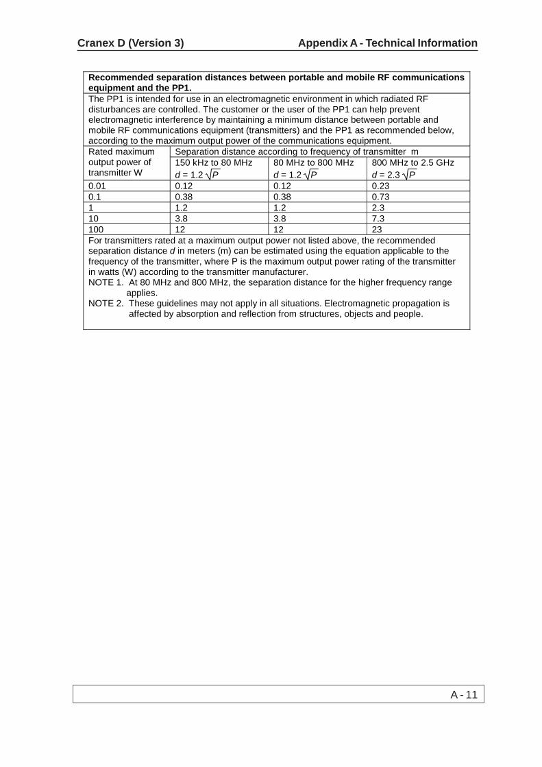
Recommended separation distances between portable and mobile RF communications equipment and the PP1. The PP1 is intended for use in an electromagnetic environment in which radiated RF disturbances are controlled. The customer or the user of the PP1 can help prevent electromagnetic interference by maintaining a minimum distance between portable and mobile RF communications equipment (transmitters) and the PP1 as recommended below, according to the maximum output power of the communications equipment.
Separation distance according to frequency of transmitter m Rated maximum output power of transmitter W
150 kHz to 80 MHz d = 1.2 P
80 MHz to 800 MHz d = 1.2 P
800 MHz to 2.5 GHz d = 2.3 P
0.01 0.12 0.12 0.23 0.1 0.38 0.38 0.73 1 1.2 1.2 2.3 10 3.8 3.8 7.3 100 12 12 23 For transmitters rated at a maximum output power not listed above, the recommended separation distance d in meters (m) can be estimated using the equation applicable to the frequency of the transmitter, where P is the maximum output power rating of the transmitter in watts (W) according to the transmitter manufacturer. NOTE 1. At 80 MHz and 800 MHz, the separation distance for the higher frequency range applies. NOTE 2. These guidelines may not apply in all situations. Electromagnetic propagation is affected by absorption and reflection from structures, objects and people.