Embed Size (px)
Citation preview

CRANFIELD UNIVERSITY
ANDREW CHAN
THE USE OF LOW COST VIRTUAL REALITY AND
DIGITAL TECHNOLOGY TO AID FORENSIC SCENE
INTERPRETATION AND RECORDING
DEPARTMENT OF MATERIALS AND MEDICAL
SCIENCES
PhD THESIS

CRANFIELD UNIVERSITY
DEPARTMENT OF MATERIALS AND MEDICAL SCIENCES
PhD THESIS
Academic Year 2004 - 2005
Andrew Chan
The Use of Low Cost Virtual Reality and Digital
Technology to Aid Forensic Scene Interpretation and
Recording
Supervisor : Dr D.W Lane
October 2005
© Cranfield University 2005. All rights reserved. No part of this publication may be
reproduced without the written permission of the copyright owner.

Abstract
ii
ABSTRACT
Crime scenes are often short lived and the opportunities must not be lost in acquiring
sufficient information before the scene is disturbed. With the growth in information
technology (IT) in many other scientific fields, there are also substantial opportunities
for IT in the area of forensic science. The thesis sought to explore means by which IT
can assist and benefit the ways that forensic information can be illustrated and
elucidated in a logical manner. The central research hypothesis considers that through
the utilisation of low cost IT, the visual presentation of information will be of
significant benefit to forensic science in particular for the recoding of crime scenes and
its presentation in court.
The research hypothesis was addressed by first exploring the current crime scene
documentation techniques; their strengths and weaknesses, giving indication to the
possible niche that technology could occupy within forensic science. The underlying
principles of panoramic technology were examined, highlighting its ability to express
spatial information efficiently. Through literature review and case studies, the current
status of the technology within the forensic community and courtrooms was also
explored to gauge its possible acceptance as a forensic tool.
This led to the construction of a low cost semi-automated imaging system capable of
capturing the necessary images for the formation of a panorama. This provides the
ability to pan around; effectively placing the viewer at the crime scene. Evaluation and
analysis involving forensic personnel was performed to assess the capabilities and
effectiveness of the imaging system as a forensic tool. The imaging system was found
to enhance the repertoire of techniques available for crime scene documentation;
possessing sufficient capabilities and benefits to warrant its use within the area of
forensics, thereby supporting the central hypothesis.

Table of Contents
iii
TABLE OF CONTENTS
Titles i
Abstract ii
Contents iii
List of Figures ix
List of Tables xii
Acknowledgements xiii
Preface xiv
Chapter 1: INTRODUCTION
1.1 Introduction 1
1.2 Project Background 2
1.3 Areas of Contribution 3
1.3.1 Forensic Illustrations 3
1.3.2 Virtual Reality 4
1.4 Thesis Structure 4
1.5 Summary 5
Chapter 2: RESEARCH OBJECTIVE AND APPROACH
2.1 Introduction 6
2.2 Aim 6
2.3 Research Hypothesis 6
2.4 Fundamental Research Questions 6
2.4.1 Requirements of the System 7
2.4.2 Points of Concerns 8
2.5 Research Objectives 8
2.6 Developmental Approach 9
2.7 Summary 10

Table of Contents
iv
Chapter 3: LITERATURE REVIEW
3.1 Introduction 11
3.2 Crime Scene Documentation 11
3.2.1 Notes 12
3.2.2 Photography 13
3.2.3 Sketches 15
3.3 Digital Photography 16
3.3.1 Nature of Digital Photography 17
3.3.1.1 Definition 17
3.3.1.2 The Basics 17
3.3.1.3 The Digital Sensor 18
3.3.2 Film Versus Digital Photography 19
3.4 Virtual Environments 20
3.4.1 Various Approach of Virtual Environments 21
3.4.2 Panorama 24
3.4.2.1 Cylindrical 24
3.4.2.2 Spherical 24
3.4.2.3 Cubic 25
3.4.3 Hardware 26
3.4.3.1 Standard Cameras (Single-Row) 26
3.4.3.2 Multi-Row 28
3.4.3.3 Video Camera 30
3.4.3.4 Panoramic Camera 30
3.4.3.5 One Shot Solutions 31
3.4.4 Stitching Software 32
3.4.5 Displaying of the Panorama 33
3.4.6 Virtual Tour 35
3.4.7 Current Areas of Use 35
3.5 Visual Aids 36
3.5.1 Types of Visual Aids 37
3.5.2 Computer Generated Displays and the Courtroom 37
3.5.2.1 USA 39
Table of Contents
v
3.5.2.2 UK 40
3.5.2.3 Persuasive Impact of Computer Images 42
3.5.2.4 Manipulation or Enhancement 45
3.6 Admissibility of Computer-Generated Evidence in the Courtroom 47
3.6.1 USA 48
3.6.1.1 Admissibility of Demonstrative Evidence 48
3.6.1.2 Admissibility of Substantive Evidence 49
3.6.1.2.1 The Frye Test 49
3.6.1.2.2 Federal Rules of Evidence 50
3.6.2 UK 51
3.6.2.1 Civil Legislation 51
3.6.2.2 Criminal Legislation 52
3.7 Standard Operating procedures 54
3.7.1 Preparation 55
3.7.2 Capture 56
3.7.3 Protection 57
3.7.4 Use 57
3.8 Technology in the Courtroom 58
3.9 IBVR and Forensic Science 59
3.10 Summary 60
Chapter 4: CASE STUDIES
4.1 Introduction 61
4.2 Case Study 1 61
4.2.1 The Case 62
4.2.2 Requirements of the Case 63
4.2.3 Presentation 63
4.2.4 The Trial 66
4.2.5 Conclusion 67
4.3 Case Study 2 67
4.3.1 The Case 68
4.3.2 Requirements of the Case 68

Table of Contents
vi
4.3.3 Presentation 70
4.3.4 The Trial 71
4.3.5 Conclusion 73
4.4 Case Study 3 73
4.4.1 The Case 73
4.4.2 Requirement of the Case 73
4.4.3 Presentation 74
4.4.4 The Trial 76
4.4.5 Conclusion 76
4.5 Case Study 4 77
4.5.1 The Case 77
4.5.2 Requirement of the Case 77
4.5.3 Presentation 78
4.5.4 The Trial 82
4.5.5 Conclusion 82
4.6 Historical Development 82
4.7 Summary 83
Chapter 5: PROTOTYPE
5.1 Introduction 84
5.2 System Architecture 84
5.3 Requirements of the system 85
5.4 Hardware 87
5.4.1 Camera 87
5.4.1.1 Field of View 88
5.4.1.2 Resolution 90
5.4.1.2.1 Focus 91
5.4.1.2.2 Focal Length 92
5.4.1.2.3 Johnson’s Criteria 92
5.4.1.3 Graphic Format 96
5.4.2 The Stage 97
5.4.2.1 Tripod 98
Table of Contents
vii
5.4.2.2 Panoramic Head 99
5.4.2.2.1 Nodal Point 101
5.4.2.3 Stepper Motors 102
5.4.2.4 Platform 105
5.5 Software Interface 106
5.5.1 Motor Control 106
5.5.2 Camera Control 109
5.5.3 User Interface 111
5.5.4 Tutorial 118
5.5.5 Software Installation 118
5.6 Summary 118
Chapter 6: APPLICATION CASE-STUDY
6.1 Introduction 119
6.2 Trial of Imaging System 119
6.3 Evaluation Approach 123
6.4 Analysis of Results 125
6.5 Refinement 135
6.6 Summary 140
Chapter 7: DISCUSSION
7.1 Introduction 141
7.2 Current Forensic Tools 141
7.3 Digital Presentation 143
7.4 Imaging System 144
7.4.1 Construction of the Proposed Imaging System 144
7.4.1.1 Camera 145
7.4.1.2 Stage 146
7.4.1.3 Software 147
7.4.2 Evaluation 148
7.4.2.1 Information 149
7.4.2.2 Usability 149

Table of Contents
viii
7.5 Applications in Forensic Science and Law Enforcement 151
7.6 Project Analysis 153
7.6.1 Strengths 154
7.6.2 Weaknesses 154
7.7 Summary 155
Chapter 8: CONCLUSIONS
8.1 Introduction 156
8.2 Accomplishment of Objectives 156
8.2.1 Develop a Background Understanding of the Core Subject 156
8.2.2 Identification of the Current Issues Surrounding the Core Subject 157
8.2.3 Investigation of Case Studies 159
8.2.4 Development of a Prototype 159
8.2.5 Evaluation of Prototype 160
8.3 Accomplishment of Central Hypotheses 163
8.4 Recommendations for Future Work 163
8.5 Summary 164
GLOSSARY OF ABBREVIATIONS 165
REFERENCES 167
APPENDICES

List of Figures
ix
LIST OF FIGURES
Figure 3.1 – Four Corner Approach. 15
Figure 3.2 – An example of the CCD Format compared to its Equivalent 18
Vidicon Tube.
Figure 3.3 – 3D CAD Model. 21
Figure 3.4 – Cylindrical Projections. 24
Figure 3.5 – Spherical Projections. 25
Figure 3.6 – Cubic Projections. 25
Figure 3.7 – Standard Camera (Single-Row) Technique. 26
Figure 3.8 – Multi-row Technique. 28
Figure 3.9 – FOX System. 29
Figure 3.10 – PixOrb Panoramic System. 29
Figure 3.11 – Spheron Camera. 31
Figure 3.12 – Portal S1 and Cyclovision Parashot One Shot Solutions. 31
Figure 3.13 – QTVR Structure. 33
Figure 3.14 – QTVR User Interface. 34
Figure 3.15 – Recommended Steps for Standard Operating Procedures. 55
Figure 3.16 – Defining Stages of Image Transfer. 57
Figure 4.1 – Photographs of the Suspect’s Clothing. 62
Figure 4.2 – Transfer of Fibres from Suspect to Victim and Vice Versa. 64
Figure 4.3 – Transfer of Red and Black Fibres onto the Deceased. 65
Figure 4.4 – Representation of Individual Red Fibre Transfer on 65
Scene Photographs.
Figure 4.5 – Illustration of Tapings through Activation of Hotspots. 66
Figure 4.6 – Original Presentation Illustrating Shoeprint Evidence. 69
Figure 4.7 – Capture Process to Create QTVR Movie. 70
Figure 4.8 – Key Areas of the Presentation. 71
Figure 4.9 – Compiled Images of the CG Presentation as Part of the Jury Pack. 72
Figure 4.10 – Screenshot Showing the Three Sections of the CG Presentation. 75
Figure 4.11 – Activation of Hotspots to Remove Layers in the Scene 75
Revealing Underlying Evidence.

List of Figures
x
Figure 4.12 – Overall Transfer of Fibres 78
Figure 4.13 – Overall Distribution of Fibres. 79
Figure 4.14 – Detailed Distribution of Fibres. 80
Figure 4.15 – Scanned Images of Tapings Taken from the Deceased. 81
Figure 4.16 – Display of Scene Photographs. 81
Figure 5.1 – Three Components of the Imaging System. 84
Figure 5.2 – Requirements of the Imaging System. 87
Figure 5.3 – FOV of Camera’s Lens 88
Figure 5.4 – Orientation of Camera. 89
Figure 5.5 – Relationship of FOV and Camera’s Dimensions 90
Figure 5.6 – Area of Focus. 91
Figure 5.7 – Three Levels of Discrimination of the Johnson’s Criteria. 93
Figure 5.8 – Representation of 1 Cycle. 93
Figure 5.9 – Requirements of Each Level of Discrimination. 94
Figure 5.10 – Process involved in Capturing JPEG, TIFF and RAW files 97
Figure 5.11 – Components of the Stage. 98
Figure 5.12 – Adjustment of Height of System. 99
Figure 5.13 – Restricted Rotation of Panoramic Head. 99
Figure 5.14 – Missing Area of Scene as a Resulted of Restricted Rotation. 100
Figure 5.15 – Attachment of Camera to the Panoramic Head. 101
Figure 5.16 – Panoramic Head and Adjustment of Nodal Point. 101
Figure 5.17 – Two Degrees of Rotation of the System. 102
Figure 5.18 – Essential Components to control Stepper Motors. 103
Figure 5.19 – Illustration of Circuit Box Connections. 104
Figure 5.20 – Position and Attachment of Platform. 106
Figure 5.21 – Access to Various Stages through Tabs. 111
Figure 5.22 – Front End of Software Interface. 112
Figure 5.23 – ‘Start’ Stage of the Capture Process. 113
Figure 5.24 – Percentage Overlap Stage. 114
Figure 5.25 – Positioning of Camera. 115
Figure 5.26 – ‘Vertical Settings’ Stage. 116
Figure 5.27 – ‘Capture’ Stage. 116

List of Figures
xi
Figure 5.28 – ‘Develop’ Stage. 117
Figure 6.1 – Limited VFOV of a Cylindrical Panorama. 122
Figure 6.2 – Blurring of the Resultant Panorama. 123
Figure 6.3 – Colour Coding of Connectors and Socket. 136
Figure 6.4 – Replacement of the Cables. 137
Figure 6.5 – Outline Demonstrating Position of Camera. 138
Figure 6.6 – Front End of User Interface. 139
Figure 6.7 – ‘Setting’s Stage. 139

List of Tables
xii
LIST OF TABLES
Table 3.1 – Dimensions of Several CCD Formats. 19
Table 3.2 – Comparison of the Two Classes of VE Techniques. 23
Table 5.1 – FOV of the Canon PowerShot G3. 90
Table 5.2 – Description of each Level of Discrimination. 93
Table 5.3 – Johnson’s Criteria for the Canon PowerShot G3 at 2m Range 95
Table 5.4 – Number of Columns and Rows for Varying Percentage Overlap 108
Table 5.5 – Features Incorporated into Software Camera Controls. 110
Table 5.6 – Commands responsible for the Features of the Camera. 110
Table 5.7 – Predefined Settings for Quick Start Mode. 113
Table 6.1 – Volunteers of the Evaluation. 125

Acknowledgements
xiii
ACKNOWLEDGEMENTS
Many thanks to all those people who have been involved throughout the term of this
research, without them this PhD would not have been possible. Particular thanks to the
following:
o Dr David Lane, my supervisor who has provided me with advice, assistance,
direction and inspiration during the course of my research.
o Members of staff at Cranfield University Defence College of Management and
Technology, including Dr Mike Cousin for his expertise in the area of computer
programming, Mike Selwood for his assistance in construction and Donald
Peach for his guidance.
o Pam Hamer and all members of staff at Forensic Alliance, the sponsor of this
project in collaboration with the Department of Material and Medical Science at
Cranfield University for their cooperation and commitment to this project.
o Special thanks to my friends and family especially my girlfriend Ann Yau for
their patience, constant encouragement and faith.
The whole is more than the sum of its parts.
Aristotle
Preface
xiv
PREFACE
The thesis aims to present an in-depth study into the use of digital and computer-
generated techniques within the forensic environment. In order to provide a
comprehensive understanding of the issues on discussion, a supplementary CD will
provide examples of the work in support of the thesis. Additional software plug-ins
which may be required for correct viewing of the examples is included in the CD.
References to the supplementary CD are denoted by the CD1 icon within the thesis.
Insertion of the CD will auto load the main page where examples are sorted by the
relative chapters and subsections in which they appear in the thesis.
References to the CD are indicated by the CD1 icon.
The project’s resultant system software is on a second CD accompanying the thesis and
is denoted by the CD2 icon within the thesis.
System Software

Introduction
1
Chapter 1: INTRODUCTION
1.1 Introduction
Forensic science has become an increasingly difficult discipline in today’s society. This
is due partly to the increase in forensic related television shows which are bringing
awareness of the forensic capability to criminals. In response to the escalating threat,
forensic science must continue improving its repertoire of techniques to counter
criminal activities and improve on the reliability of existing methods. The manner that
we operate certain tasks in everyday society has no doubt been influenced by the
presence of information technology (IT); the forensic communities are no exception.
With the rapid growth in IT in other scientific fields, there are also substantial
opportunities for IT in the area of forensic science. In order to gauge the potential, the
question must be asked to ‘How can professionals take advantage of these benefits
without compromising their work?’
Although digital imaging technologies have been used in a variety of scientific fields for
decades, their application in the criminal justice system has been relatively recent
[SWGIT, 2001]. The computer, as a visual medium offers a substantial number and
variety of facilities for the production, manipulation and presentation of visual imagery,
which presents new perspectives and techniques for its application in forensic science.
The exploitation of computers as a tool for presentation of images in the courtroom
opens up opportunities for the communications of information in an innovative, yet
increasing familiar manner as a result of television and home computers.
Traditionally law enforcement agencies have relied on the three basic methods of
documenting a crime scene: sketches, film photography and written notes. Accurate
recording of crime scenes in their original state is essential for both subsequent
investigation and presentation in court, which relies on the accuracy and comprehension
of these records. Tying together these records in a logical manner requires expert
administration and immense concentration from those viewing the evidence. These are
exacerbated when the crime scene needs to be ‘revisited’ weeks, months or even years
later.
Introduction
2
It is of paramount importance that the jury and all personnel involved in the
investigation understands as fully as possible all aspects of the crime scene. Although
traditional techniques of crime scene documentation cannot be replaced, they may not
necessarily form the best method to record and illustrate the crime scene. “I think what
the police service lacks at the moment are the systems for documenting, recording and
assessing evidence found in the open air which can show the relationships between
pieces of evidence,” says Detective Superintendent Newman, of Avon and Somerset
Constabulary [Adams, 1998].
In three dimensional (3D) worlds, we continue to record and analyse using two
dimensional (2D) visual documents of sketches and photographs. These techniques are
effective and widely accepted, although they are not without its drawbacks. Current
documentation techniques greatly restrict the actual visualisation of the incident,
requiring a careful cross referencing of the details in order to understand it. With the
use of various technologies, it is possible to deceive the eyes into a 3D perception. This
has the potential to allow for more efficient observation of a crime scene and ultimately
provide an invaluable tool in the process of crime scene documentation.
Application of novel technology in the forensic community warrants careful
consideration. Prior to the acceptance of such technology, they face the questions of
reliability of the technology and acceptance within court. Without such deliberation,
such novel technology may prove to be worthless regardless of the potential benefits
that it may bring.
1.2 Project Background
The project has stemmed from advances in digital imaging and the need for greater
flexibility in the area of crime scene documentation; taking into consideration the
current laws regarding admissibility of evidence.
Several projects by students on the Cranfield University MSc in Forensic Engineering
and Science have illustrated potential advances in the application of digital imaging in
Introduction
3
forensic science [Chan, 2002] [Garnier, 2002]. These have provided awareness of the
potential benefits and applications of such studies to the commercial industry.
Part funded by Forensic Alliance (FA) which is now a part of LGC, this project forms
the first PhD collaboration with Cranfield University. Liaison with FA was led by Ms
Pam Hamer; head of Research and Development at FA who has over thirty years
experience as a forensic scientist. Supervisor to the project was Dr David Lane; a senior
lecturer in the Cranfield University Centre for Materials Science and Engineering, and
the Chairman of the University’s MSc in Forensic Engineering and Science.
1.3 Areas of Contribution
Throughout the course of the research presented in the thesis, contributions have been
made to several different fields of knowledge. The following sub-sections (1.3.1-1.3.2)
addresses the contributions that the thesis makes. These are derived from exploring the
concept of various imaging and computer-generated (CG) techniques and their impact
within the field of forensic science.
1.3.1 Forensic Illustrations
The application of CG illustrations in forensic science is relatively recent and its
development has been rapid. This thesis makes the following contributes to the
knowledge of forensic illustrations:
• The integration of widely available commercial off-the-shelf components into
a single digital panoramic camera system to provide a low cost solution in the
documentation of crime scenes.
• Application of virtual environments (VE) in the forensic community at any
specific stage of an investigation. Benefits of such tools extend far beyond the
initial onset of an investigation. Particular benefit of the communicative
nature of the system can be seen in its application not only throughout the
investigation but also in the courtroom.
• Although in the United Kingdom (UK), the application of digital images in
court is relatively new, its use in the United States (US) is more established.

Introduction
4
The thesis provides a study of the admissibility of digital images and CG
evidence in the courtroom within the UK and US, and the difficulties that have
arisen as a result of its use. This will aid a smoother transition in the use of
digital images as an alternative to more traditional film-based images.
1.3.2 Virtual Reality
The thesis makes the following contributions to the area of virtual reality (VR):
• Exploration of different techniques for the creation of VR has provided a
useful insight into its application and potential in the forensic community.
• The cost required for the creation of a VR is typically out of reach of all, but
the most high profile cases. By using varied VR techniques, it has enabled the
creation of low cost VEs which are accessible to any cases from petty crime to
homicides.
1.4 Thesis Structure
This section outlines the structure of the remaining chapters by providing a brief
description of the intended contents of the thesis. This is as follows:
• Chapter 2 presents the general aim, hypothesis and approach of the thesis. The
fundamental research questions posed in this chapter aim to develop and drive
the research forward.
• Chapter 3 describes the theory upon which the main body of work is based,
and explores the established principles within the forensic and IT
communities. It also presents research that has been conducted in this area
and addresses the principles and approaches that have been tried and tested;
taking into consideration the outcome of such an approach.
• Chapter 4 presents a number of case studies that have been carried out during
the course of the research and that have involved the use of digital imaging
and CG techniques. It addresses key issues relating to actual requirements
from the forensic and law enforcement communities regarding submission of
digital presentation in court. †

Introduction
5
• Chapter 5 describes the approach to the development of a prototype imaging
system and explores the parameters of the individual components that
comprise the resultant system.
• Chapter 6 presents the evaluation of the prototype. It addresses its usability
and scrutinises the capability of the system. It describes the views of the
potential users and the impact that the prototype imaging system may have on
their work.
• Chapter 7 discusses the results of the research. It presents a discussion on a
number of areas covered within the thesis and presents a detailed account on
the prototype imaging system.
• Chapter 8 presents the conclusion from the research by drawing upon the
research results and discussions. This chapter also discusses the achievements
of this work based upon the original aims and objectives that were established.
Suggestions for future work are also presented in this chapter.
1.5 Summary
This chapter has laid the foundation for the thesis. It has introduced the thesis through a
forensic context and provided justification for the research. A description of the
background of the project has been outlined and the specific contribution that the thesis
makes to varies fields. Finally, the chapter presented an outline of the structure of the
thesis to provide an overview of what is to follow. Beginning with the aim of the
project, the thesis now provides a detailed description of the research by formulating the
objective of the project, and the intended approach.
† Coyle, T., Larkin, A., Smith, K., Chan, A., Hunt, N. (2004). Fibre Mapping – A
Case Study. Science & Justice. Volume 44 Number 3. Pages 179-186.

Research Objective and Approach
6
Chapter 2: RESEARCH OBJECTIVE AND APPROACH
2.1 Introduction
This chapter presents the broad aim of the project and lays the foundation for the main
research. It allows for the formulation of the project’s main objectives and brings up
fundamental research questions that need to be explored. The chapter also identifies the
research approach taken in order to address and achieve the aim and objectives.
2.2 Aim
The broad aim of this research project is to explore the use of modern technologies in an
attempt to develop a viable forensic tool for the recording of crimes scenes. It is
envisaged that such novel system would deliver a high quality and cost effective
technique to create accurate records of crimes scenes, whilst still in their original
untouched state.
2.3 Research Hypothesis
Based on the broad aim of the research project outlined above, the following hypothesis
was postulated:
“Through the utilisation of low cost IT, the visual presentation of
information will be of significant benefit to forensic science in particular
for the recording of evidence and its presentation in court. If a scene
could be captured in such a way that offers the viewer the ability to
move freely, as if he or she were present at the actual scene, it would be
advantageous at various stages of an investigation from the initial crime
scene to the courtroom”.
2.4 Fundamental Research Questions
In order to drive the research forward, numerous discussions took place with the staff at
FA regarding the needs, requirement and concerns about the development of the
proposed imaging system. In order to provide a viable system capable of forensic
Research Objective and Approach
7
application, the following fundamental research questions were posed to aid the
development and refinement of the research objectives.
2.4.1 Requirements of the System
The intended end users of the system are the forensic scientist and scenes of crime
officers (SOCOs). It is beneficial to encompass as much of their requirements as
possible. Meetings with the staff of FA helped establish the following requirements of
the system:
• Low Cost – Law enforcement agencies already face cost limitations therefore;
the need to employ a low cost solution for delivering an imaging system for
recording a crime scene is paramount.
• Ease of Use – The technological knowledge of users are often diverse; the
ability to operate complex equipment can deters the user from implementing
the system. Ease of use of the system is an essential requirement and should
enable any user of any ability to operate with little difficultly.
• Portability – Portability of the system is an important issue due to its intended
use in remote locations. Consideration must be given to the weight and
compactness of the system.
• Durability – Knocks and bump often accompany the transit and operation of
the system which will have a direct impact on the reliability of the system.
The need for a durable system will ensure that the equipment is reliable and
able to perform its function.
• Time – A crime scene in its original untouched state is often short lived. A
system is required that captures the required images as quickly as possible and
does not prolong the process of documentation further.
• Quality – The quality of the output images is an important consideration. Low
quality images will provide little use as a recording tool. Consideration must
be given when deciding on the appropriate hardware.

Research Objective and Approach
8
2.4.2 Points of Concerns
In addition to the system requirements, personnel at FA raised several points of concern
that related to the user confidence in the proposed system:
• Low cost solutions are always perceived as being inferior to a more expensive
equivalent. Although this may sometimes be true, the accuracy to which it
depicts the crime scene and whether this is of sufficient quality is more
important, and this may not be related to cost.
• Reliability of the system is an important issue and the deployment of the
system must result in the performance as intended.
• In specialised professions such as forensic science and law enforcement,
creditability of the system will play an influential part in establishing its
successful deployment. The ability to tamper with the resultant images should
be carefully investigated and measures taken to avoid any bias in the imaging
system.
• The potential of the imaging system to be used not only for subsequent
investigation but also application in the courtroom as a method of
communicating the layout of the scene to the jury is a significant advantage.
Therefore, the admissibility of graphical presentation in court is an important
issue, and must be carefully examined to bring awareness of possible
problems that may be faced.
2.5 Research Objectives
In order to derive the research objectives of the thesis, it was necessary to inspect and
consider the core aim of the thesis and the research hypothesis. In addition, careful
consideration was given to the requirements of the sponsor and the points of concerns
that were made aware in section (2.4). These led to the identification of a number of
specific research objectives that would need to be addressed, as follows:
(i). Develop a background understanding of the core subject – There is a
necessity to gain an extensive understanding of the fundamental crime scene
documentation techniques that are currently being implemented by the law

Research Objective and Approach
9
enforcement communities which will illustrate their associated strengths and
weaknesses. In addition, understanding the basic digital imaging concepts and
the broad area of VEs will be beneficial to the requirements in the development
of a prototype imaging system.
(ii). Identification of the current issues surrounding the core subject – There
would be a need to explore current issues surrounding the use of digital imaging,
VEs and CG evidence in a forensic context. This will allow us to gauge the
possible acceptance and implementation of such technology.
(iii). Investigation of case studies – Use of case studies from genuine crime scenes
cases would be performed in collaboration with FA, in order to assess the
potential of CG illustrations and digital images in the courtroom. This
evaluation would provide first hand experience on the general perception of
digital imaging and CG evidence in today’s courts and within the forensic
community.
(iv). Develop a prototype – A semi-automated imaging system should be developed
and constructed which captures digital images for the creation of virtual records
of crime scenes using complete panoramas with the ability to view and rotate
within the scene. Recording the scene in this way would provide a permanent
and robust recording in support of traditional crime scene documentation
techniques. This would also aid in the assessment of various scenarios during
subsequent investigation.
(v). Perform an evaluation – An evaluation of the developed prototype would be
performed with the intended end users of the system. This aims to assess the
adequacy of such system for its intended purposes. Assessment would be based
on the importance of capabilities in forensic science and how well this was
realised by the technology.
2.6 Developmental Approach
In order to achieve the research objectives (IV) and (V) set out, the developmental
approach will be detailed to provide a guideline by which the construction of the
imaging system will progress. This will be divided into several stages of development,

Research Objective and Approach
10
encompassing investigation of the technology and its parameters. These stages of
development include: the camera, stage and software.
1) Camera – The quality of the digital camera implemented within the system has a
direct affect on the overall quality of the generated panorama. It is important that
the correct digital camera is selected based on the requirements of the system. In
addition, the limits of the digital camera in terms of the field of view and visual
detail should be determined in order to identify the capabilities of the system.
2) The Stage – The purpose of the stage is to provide a platform which encompasses
all the components of the system including the digital camera. It will accommodate
stepper motors which are intended to provide the necessary rotation of the digital
camera for image capture.
3) Software – Through the use of computer programming, it is the role of the software
to combine the ability to control the camera’s capture process and rotation of the
stepper motors into a central user interface.
The final part of the research is concerned with devising and executing a trial using the
prototype imaging system with user-group representatives in order to establish the
achievement of the aim and objectives. The empirical results collected from the trial
would be evaluated and analysed to determine the general perception of the imaging
system and its value as a forensic tool.
2.7 Summary
This chapter has defined the central hypothesis of this thesis, by first introducing the
broad aim of the research project. It then posed fundamental research questions from
which the main research objectives have been derived. Finally, the chapter has
identified the strategy that would be adopted in order to meet these objectives. From
this point, the thesis now proceeds to describe the existing intellectual body of
knowledge, the theory, which underpins the research.

Literature Review
11
Chapter 3: LITERATURE REVIEW
3.1 Introduction
This chapter focuses on two areas of research; the existing body of knowledge upon
which the main bulk of the research is based and the research that has been conducted in
this area.
The first section of this chapter will provide an outline of the fundamental techniques
currently employed by law enforcement communities for crime scene documentation.
The section then describes the value of digital photography and also provides an in-
depth study of virtual environments (VEs) and their methods of construction.
The second section is concerned with the current application of visual presentation
within the courtroom. By analysing approaches that have already been used provides a
great deal of knowledge that can be applied to the current research and aid in gauging
the usefulness of the proposed imaging system as well as its acceptance and transfer to
the courtroom. This section will derive from more traditional techniques of visual aids,
the benefits of visual presentations. Since the judicial system varies between countries,
the issues of CG displays may also differ and will be explored. Focus will be placed on
the use of CG within the UK, drawing from the experiences of more established
countries such as the US. In particular, discussions on the benefits and detriments of
using CG display and evidence in courts will be examined, including the admissibility
of such evidence. The ability of courtrooms to accommodate the technology will also
be covered.
3.2 Crime Scene Documentation
The goal of a criminal investigation is to assist in establishing the series of events that
may have transpired and identify the accountable party. This is achieved through
careful documentation of the crime scene and recognizing all relevant physical
evidence. “Physical evidence encompasses any and all objects that can establish that a
crime has been committed or can provide a link between a crime scene and its victim or
a crime and its perpetrator” [Saferstein, 2001]. Crime scene documentation is often the

Literature Review
12
most time consuming step in an investigation. There is a limited amount of time where
a crime scene remains in its untouched state and the opportunity must not be lost in
acquiring as much information as possible before the scene is disturbed. These records
are important, not only throughout the subsequent investigation but may also be
valuable for the purposes of re-evaluation of scenes or ultimately for use in the
courtroom.
The principles of crime scene documentation are to record and preserve the condition of
the crime scene. This also serves to documents the location and relationship of physical
evidence within the scene. Crime scene documentation commences at the moment an
investigation begins and should take precedent over any examination of the scene.
Although no two crime scenes are ever the same, SOCOs will adhere to certain crime
scene protocol and procedures in the processing of the scene. This will ensure that the
integrity of any evidence recorded is maintained and aid its admissibility in court.
The three main methods for crime scene documentation comprise of notes, photography
and sketches. Although individually, these techniques may be inadequate to provide a
detailed documentation of the scene; their combined strength provides a complete and
detailed account that is required for subsequent analysis of the scene. All three methods
should be employed at a scene to ensure completeness of recording.
3.2.1 Notes
SOCOs are faced with an ever increasing need to document the scene as thoroughly as
possible. Note taking forms the first of these techniques and perhaps one of the most
important stages of crime scene documentation. From the onset of an investigation and
throughout the processing of the scene, notes are taken continuously by the SOCO.
These will not only be invaluable during the subsequent investigation but may serves as
a reminder of the case months, perhaps years later.
A detailed written description of the scene should encompass a complete record of
everything observed and accomplished during the investigation. Although, there are no

Literature Review
13
specified guidelines in the note taking process, there is certain information that should
be included in such recording [Lee, 2001]:
• Type of crime.
• Date and time the crime was first reported.
• Identification and details of first reporting officer.
• Details from any witness and other personnel of importance.
• Description of the scene including weather, location and surrounding areas.
• Description of the primary crime scene, including the location and state of any
bodies.
• Identification of any physical evidence found at the crime scene.
• Details of crime scene documentation including photographs and sketches.
• Recording details of the evidence processing, collection, packaging, and
transportation stage.
• Conclusion of the crime scene investigation should be documented with the
date and time.
The extensive list is by no means comprehensive and represents only some of the
information that should be included in the note taking process. Note taking can be a
slow and laborious activity especially when presented with a scene that may possess
numerous pieces of evidence. One such technique to tackle this is with the use of a
pocket tape recorder [Fisher, 2000]. This provides a faster medium by which the
thoughts and observation of the SOCO can be noted. However, the tape must be
transcribed into a written format at some stage.
3.2.2 Photography
Photography is one of the most useful tools in the arsenal of crime scene documentation
techniques; by providing a permanent visual record of the scene and its related areas.
The saying, “one picture is worth a thousand words” is certainly true in respect to crime
scene photography. A photograph provides an accurate depiction of the scene that
surpasses any verbal description that an investigator can communicate. The same is true
for written reports where Staggs says “Whatever type of crime scene an investigator is

Literature Review
14
faced with, photographs can communicate more about crime scenes and the appearance
of evidence than the written report” [Staggs, 1999].
While photographs provide valuable aid during the subsequent investigation, they are
particularly important in communicating the scene to the jury. Very rarely does the jury
visit the scene; therefore photographs provide the only opportunity for the scene to be
observed.
An important step in photographing a crime scene lies in properly logging each
photograph taken. This process is intended to prevent any confusion as to what the
photograph is depicting and the location it was taken. These should also include the
date and time at which the photograph were taken and the camera setting utilized to
capture the photographs.
The most important prerequisite for photographing a crime scene is to have it in an
unaltered condition [Saferstein, 2001]. Therefore, before anything is touched and a
detailed examination of the crime scene takes place, the crime scene should be
photographed. Photographs must be an accurate representation of the crime scene and
the evidence [Staggs, 1999]. Poorly captured crime scene photographs can directly
affect the success of a crime scene investigation. In order to ensure a complete
photographic documentation of the crime scene and its related evidence, a three step
approach is normally employed [Staggs, 1999]:
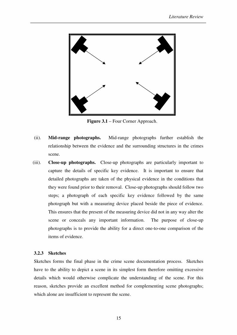
(i). Overall photographs. Overall photographs enable the depiction of the entire
scene and allow the visualisation of the scene as the photographer, first saw.
When shooting the overall scene, the photographs should show the layout of the
crime scene and the overall spatial relationship of the various pieces of evidence
to each other [Schiro, Accessed 2006b]. In order to provide a complete
coverage of the scene, the four corner approach as illustrated in Figure 3.1 can
be utilised.
Literature Review
15
Figure 3.1 – Four Corner Approach.
(ii). Mid-range photographs. Mid-range photographs further establish the
relationship between the evidence and the surrounding structures in the crimes
scene.
(iii). Close-up photographs. Close-up photographs are particularly important to
capture the details of specific key evidence. It is important to ensure that
detailed photographs are taken of the physical evidence in the conditions that
they were found prior to their removal. Close-up photographs should follow two
steps; a photograph of each specific key evidence followed by the same
photograph but with a measuring device placed beside the piece of evidence.
This ensures that the present of the measuring device did not in any way alter the
scene or conceals any important information. The purpose of close-up
photographs is to provide the ability for a direct one-to-one comparison of the
items of evidence.
3.2.3 Sketches
Sketches forms the final phase in the crime scene documentation process. Sketches
have to the ability to depict a scene in its simplest form therefore omitting excessive
details which would otherwise complicate the understanding of the scene. For this
reason, sketches provide an excellent method for complementing scene photographs;
which alone are insufficient to represent the scene.

Literature Review
16
Sketches have an advantage over photographs as they can accurately depict the spatial
relationship of objects in the scene which may appear distorted in photographs due to
their 2D representation of 3D objects. The advantages of a crime scene sketch are in
providing a permanent record of the actual size, distance and relationship of the crime
scene and its physical evidence [Lee, 2001]. These should include the dimension of the
scene and show the location of all objects having a bearing on the case [Saferstein,
2001]. There are two basic types of crime scene sketches used as part of a crime scene
investigation: a rough sketch and a final sketch [Lee, 2001].
Crime scene sketches commences with a simple rough sketch which entails the
representation of all relevant structures in and around the crime scene. With the use of a
tape measure, objects in the scene should be located in the sketches by distance
measurement from two fixed points, such as the walls of a room [Saferstein, 2001]. The
final sketch can be completed at a later date and should be drawn with care, reflecting
on the information contained within the rough sketch. The availability of computer
programs such as Computer-Aided Design (CAD) allows the process of completing a
final sketch to be less labour intensive.
3.3 Digital Photography
The rapid growth in technology is continually changing the ways in which forensic
experts operate. These provide an improved and more efficient means for performing
their work. Digital photography is one such technology that is rapidly gaining
popularity within the field of forensic science; as an additional tool in crime scene
documentation procedures.
The relatively novel nature of digital photography in the forensic and law enforcement
communities presents numerous concerns regarding its value and credibility. Through
considerations of these concerns and a greater understanding of the underlying
principles of the technology, the potential acceptance of the proposed imaging system
can be gauged. Investigating the following questions regarding digital photography and
CG displays through the course of this chapter will provide invaluable information that
can be applied to the proposed imaging system:

Literature Review
17
• What is digital imaging?
• What are the advantages and disadvantages of digital photography compared
to traditional photography?
• Are the existing portions of the law that deal with digital recording as evidence
adequate for digital images?
• What is the current acceptance of the use of digital images and CG displays in
court?
• Are courts adequately equipped to deal with the presentation of computer
aided presentations?
• How has the use of digital imaging and CG displays in court developed in the
U.K compared to the rest of the world?
3.3.1 Nature of Digital Photography
Digital photography can provide numerous benefits including enhancement in the
accuracy and quality of work. However, the nature of digital photography also brings
some disadvantages that may possibly impede the outcome of an investigation. The
unique quality of digital photography results from its hybrid nature of being part
photograph, part computer data.
3.3.1.1 Definition
What is a digital image? “A digital image (or photograph), as it will be used in the
thesis, is a numerical representation of an image recorded simple as a series of binary
digits (bits); either one or zero with no values in between” [House of Lords, 1998].
3.3.1.2 The Basics
The structure of a digital image consists of a very large number of picture elements
called pixels, arrayed in some regular pattern. Each pixel is a set of discrete numbers
consisting of bits of information representing a specific colour, intensity and location in
the array. The number of pixels in an image has a direct bearing on the quality of a
digital image in terms of its sharpness and clarity, i.e. the more pixels per inch (ppi)
denotes better quality.

Literature Review
18
3.3.1.3 The Digital Sensor
The underlying principles of conventional film photography also holds true for digital
photography in terms of the way that light is used to create an image. The difference lie
in the image sensor used to capture the image. Instead of using light sensitive film to
record an image; most digital cameras use a light sensitive chip called a charged
coupled device (CCD) or in some cases complementary metal oxide semiconductor
(CMOS) to record the image electronically.
CCD sensors are often referred to using imperial fractions such as 1/1.8" or 1/3". This
type of designation follows a set of standard sizes, given to television camera tubes in
the 50's. This naming convention was carried over to CCD sensors and they were sized
according to the size they would be if they were a Vidicon tube. The imperial fractions
represent the diameter of the Vidicon tube. Although it has no direct relationship on the
size of the imaging sensor; it is always roughly two thirds [dpreview, Accessed 2006].
Figure 3.2 shows the difference in size of the CCD imaging sensor in comparison to its
corresponding Vidicon tube size. Table 3.1 represents the dimensions of several
common CCD formats.
Figure 3.2 – An example of the CCD Format compared to its Equivalent Vidicon Tube.

Literature Review
19
Sensor Size (mm)
Format Width Height Diagonal
1/6" 2.15 1.61 2.7
1/4" 3.2 2.4 4
1/3.6" 4 3 5
1/3" 4.8 3.6 6
1/2" 6.4 4.8 8
1/1.8" 7.176 5.319 8.932
2/3" 8.8 6.6 11
Table 3.1 – Dimensions of Several CCD Formats.
3.3.2 Film Versus Digital Photography
The ever expanding field of technology has not only brought about an increase in the
quality of digital photography but an enhanced sense of familiarity. Both conventional
film photography and digital photography share many similarities, yet display a range of
attribute belonging only to a specific medium. The advantages and disadvantages of
these characteristic will demonstrate the strengths and weaknesses of digital
photography.
In the past, the quality of images captured using conventional film photography
surpasses those obtained with a digital camera; achieving higher resolution and greater
dynamic range. This allowed for superior capture of both shadow and highlight details
over its digital counterpart. Redsicker says “With each passing day, the quality of the
two mediums becomes harder to differentiate” [Redsicker, 2001]. This is certainly true
with the expanding technology as digital cameras have become so advanced that the
balance of quality has been shifted in its favour. This is evident in the Spheron digital
camera with a dynamic range of up to 26 aperture stops and the Hasselblad H2D digital
camera with a 39 mega pixels capability. Conventional film cameras are generally less
expensive than high resolution digital camera costing in the region of $32,000 for the
Hasselblad H2D digital camera.
Perhaps one of the greatest qualities of digital photography is their ability to provide an
instant evaluation of the captured image through a liquid crystal display (LCD) screen,
available on most digital cameras. The advantages of a preview ensure that a superior

Literature Review
20
quality image has been captured with the correct exposure and lighting as well as all
relevant parts of the scene. Inadequate images can be determined quickly and taken
again. Images can be transferred directly to a computer for more detailed viewing or
printed for a hard copy. This eliminates the need for a chemical photo lab; required by
conventional film photography and therefore there no negatives that can be lost or
damaged during processing [Advanced Imaging and Analysis, 1998]. This can also
improve health and safety and provide a low cost and time saving solution in capturing
images.
The absent of image degradation is limited to digital information. In digital
photography, a copy of an image results in a precise duplication; with no loss in image
quality between generations. This is one of the great benefits of digital technology
[House of Lords, 1998]. Contrastingly conventional film photography is analogue in
nature and therefore a copy of an image provides an inferior copy and further copy of a
copy produces further degradation in quality.
Controversy surrounds digital photography in regards to the ease in which digital
images can be manipulated and enhanced. There exists a wide variety of commercially
available graphic software that gives users the ability to alter images with little
difficulty. Shared by many is the misconception that conventional film photography
cannot be altered which further strengthens the belief that digital images are inferior to
their conventional counterparts [Advanced Imaging and Analysis. 1999].
Distinguishing between enhancement and manipulation is an important step in tackling
these concerns and the use of standard operating procedures (SOP) will help in ensuring
admissibility.
3.4 Virtual Environments
Traditional means of crime scene documentation are effective, yet they are slow and
cumbersome. While a photograph captures a scene from a single viewpoint, a VE offers
the advantage of multiple viewpoints from the same location. VE; a type of VR is an
“interactive real time environment that is simulated by a computer and responds to user
input and action” [Schofield, 2002]. A key component in most VR systems is the

Literature Review
21
ability to perform a walkthrough of a VE from different viewing positions and
orientations. It engages the user with interactivity, imparting an experience of actual
present. The use of VR has mainly been associated with training applications; i.e. flight
simulations used to train pilots. With the rapid development in computer technology,
applications of VR are becoming more common place in many areas including law
enforcement. The computer game industry has driven this technology forward and
brought its potential to a wider audience.
This thesis explores the application and benefits of VR technology in the documentation
of crime scenes. In the past, the difficulties associated with the construction of a VE
were immense; requiring expertise in computer graphics. However, with growth in
computer software, it has become a simpler task.
3.4.1 Various Approach of Virtual Environments
There are two types of VEs: graphics based virtual reality (GBVR) and image based
virtual reality (IBVR). These vary significantly in terms of the appearance, interactivity
and user freedom. Advantages and disadvantages associated with each of these
methods will be discussed in this section.
GBVR is the traditional means of generating a VE. This is a geometry based approach
and essentially is a collection of 3D geometrical entities. Using CAD software, physical
measurements and blueprints, accurate constructions of VE can be achieved. An
example of CAD constructed VE is shown in Figure 3.3.
Figure 3.3 – 3D CAD Model [Gibson, 2000].

Literature Review
22
One of the fundamental weaknesses of GBVR is the lack of realism that is exhibited.
Studies have been carried out in an attempt to enhance the VE by application of texture
maps and other techniques onto the surface of 3D models [Kang, 1999]. This provides
an enhanced sense of immersion that the user experiences. GBVR allows the user the
freedom to explore the VE from any angle or position within the scene. This flexibility
of movement within the scene is an important and beneficial aspect of GBVR that is not
shared by IBVR.
There are a number of problems associated with the GBVR approach. The first problem
is the cost of construction. Since the process of building a 3D CAD model is both
labour intensive and requires much expertise, only the simplest or most high profile of
cases can warrant its use. The rendering performance of GBVR is dependent on the
complexity of the constructed scene. Therefore, in order to achieve a real time
performance, GBVR scenes require high quality graphics accelerators to render the
scene adequately. Although the cost of graphics accelerators have decrease over the
years and become standard equipment in most personal computers, Chen says “real time
rendering problem still remains since there is really no upper bound on rendering
quality or scene complexity” [Chen, 1995]. This is one of the fundamental
disadvantages of GBVR. The complexity of a scene is directly related to the number of
objects that the creator decides to construct.
The application of GBVR in a forensic setting has been more widespread than IBVR.
Studies have been in progress which attempt in tackling some of the problems of GBVR
that have been discussed and also its application within the forensic field. One such
study is the Reconstruction of Virtual Environments with Accurate Lighting (REVEAL)
project; carried out by the University of Manchester and in collaboration with the
Greater Manchester police force. The focus of the REVEAL project is the investigation
of a semi-automatic techniques that aid in the extraction of geometric and illumination
information from photographs in the construction of a VE [Gibson, 2000]. The result of
the study was applied to scene of crime reconstruction and provided value data for
further studies.

Literature Review
23
Due to the problems encountered with GBVR, there has been the emergence of a
competing means of creating VE known as IBVR. This alternative technique possesses
some of the benefits of a 3D model at a fraction of the cost. The image based approach
constructs a VE by utilising a series of photographs at a number of viewpoints to
generate a panorama for each viewpoint. Through the advances in panoramic hardware
and software, simulation of photo-realistic VE is made possible.
IBVR is a combination of CG and digital images that allows navigation through a scene
and delivers a high quality photorealistic VR experience, opposed to the use of
polygons employed with GBVR. Where real time rendering of GBVR is affected by the
complexity of the scene, IBVR has no such restriction [Li, Accessed 2006]. Due to the
fixed dimension of each panoramic image, the number of pixels to be processed is also
limited [Chiang, 1997]. This feature allows a smooth navigation even in arbitrarily
complex and detailed scenes [Cuntz, 2002]. IBVR demands less computing power and
allows playback at interactive speed without the need for hardware acceleration; though
it places high demands on the system memory.
Construction of a VE using the image based approach is restricted to a 2D
representation and users cannot freely explore or interact with objects in 3D world space
[Chiang, 1997]. Interaction of IBVR systems is limited to the viewpoints from which
the images were captured. Table 3.2 shows the comparison between the two classes of
VE techniques. This thesis will focus upon the use of IBVR as the principle method of
constructing a VE. The following subsections will expand on the techniques of IBVR
and its various subtypes.
Graphic Based Virtual Reality (GBVR) Image Based Virtual Reality (IBVR)
Explicit use of 3D models Directly uses collection of images
Uses conventional rendering pipeline Based on interpolation or pixel
reprojection
Speed dependent on scene complexity Speed independent of scene complexity
Relies on hardware accelerator for speed Relies on processor speed
Requires sophisticated software for realism
Realism dependent on input images
Table 3.2 – Comparison of the Two Classes of VE Techniques [Kang, 1999].

Literature Review
24
3.4.2 Panorama
An interactive panorama is an IBVR; an unusually wide image of a scene. Through the
use of an environment map, a panoramic image becomes an immersive experience. An
environment map is a projection of a panorama onto a simple shape [Chen, 1995]. The
perspective of a panoramic image is changed by software in order to present a realistic
display of the panorama on a computer screen. The absence of such projection results
in a distorted appearance. An interactive panorama creates the feeling of actually being
present at the scene itself and offers in some cases a full 360° by 180° view. The actual
horizontal and vertical range is determined by the environment map utilized [Apple
Computer, 2005] along with the hardware and techniques used to capture the images.
Currently there are three different types of environmental maps: cylindrical, spherical
and cubic [Jacobs, 2004].
3.4.2.1 Cylindrical
A cylindrical panorama is the most common type of environmental maps. It is achieved
by projection onto the inside of a cylinder giving the feeling of standing inside a can. A
cylindrical projection is shown in Figure 3.4. This allows panning left and right by
correction of distortion horizontally to give a picture that looks more normal.
Cylindrical panoramas are limited by their vertical field of view (VFOV) and therefore
do not possess the ability to pan directly up and down. Correction is not applied
vertically and panoramas achieved through wide angle lenses will appear distorted
[Panoguide, Accessed 2006].
Figure 3.4 – Cylindrical Projections.
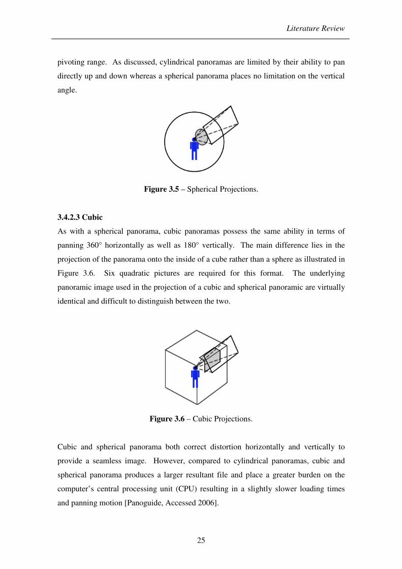
3.4.2.2 Spherical
Spherical panoramas are achieved through the projection onto the inside of a sphere
giving the feeling of standing inside a bubble as illustrated in Figure 3.5. The horizontal
capability of a spherical panorama allows the viewer to pan 360°. Spherical panoramas
offer greater flexibility than the simpler cylindrical panorama in terms of the vertical
Literature Review
25
pivoting range. As discussed, cylindrical panoramas are limited by their ability to pan
directly up and down whereas a spherical panorama places no limitation on the vertical
angle.
Figure 3.5 – Spherical Projections.
3.4.2.3 Cubic
As with a spherical panorama, cubic panoramas possess the same ability in terms of
panning 360° horizontally as well as 180° vertically. The main difference lies in the
projection of the panorama onto the inside of a cube rather than a sphere as illustrated in
Figure 3.6. Six quadratic pictures are required for this format. The underlying
panoramic image used in the projection of a cubic and spherical panoramic are virtually
identical and difficult to distinguish between the two.
Figure 3.6 – Cubic Projections.
Cubic and spherical panorama both correct distortion horizontally and vertically to
provide a seamless image. However, compared to cylindrical panoramas, cubic and
spherical panorama produces a larger resultant file and place a greater burden on the
computer’s central processing unit (CPU) resulting in a slightly slower loading times
and panning motion [Panoguide, Accessed 2006].
Literature Review
26
3.4.3 Hardware
The increase interest in panoramic images by professionals and the public have driven
the technology forward and there now exists a wide range of commercial hardware and
software techniques available for generating a panorama. Although the resultant
panorama are visually similar, the techniques differ in terms of the quality of the
captured images, the cost of equipment, the degree of vertical pivotal range and the
required image stitching process. These techniques are discussed further.
3.4.3.1 Standard Cameras (Single-Row)
Perhaps one of the most common techniques used to capture the images required for the
creation of a panorama is the utilisation of standard off-the-shelf cameras. This
generally does not require expensive equipment and therefore provides a low cost
solution to generating a panorama; bringing the technology not only to professionals but
to the general public.
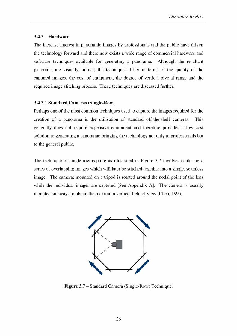
The technique of single-row capture as illustrated in Figure 3.7 involves capturing a
series of overlapping images which will later be stitched together into a single, seamless
image. The camera; mounted on a tripod is rotated around the nodal point of the lens
while the individual images are captured [See Appendix A]. The camera is usually
mounted sideways to obtain the maximum vertical field of view [Chen, 1995].
Figure 3.7 – Standard Camera (Single-Row) Technique.

Literature Review
27
The degree of rotation of each image required to achieve the desired percentage overlap
is dependent on the field of view (FOV) of the respective lens. A recommended overlap
of at least 30% and no more than 50% is usually cited [Anderson, Accessed 2006].
With such overlap, it provides sufficient common points for greater accuracy in the
subsequent stitching process. A large percentage overlap has the affect of increase
quality of the panorama and a more subtle transition between each image.
Consequently it requires the capture of a greater number of images, which not only
requires more time for the capture and stitching process, but also places a greater burden
on the system memory during playback. Particular disadvantage of this technique is its
vulnerability to movements of objects within the scene from one image to the next,
resulting in blurring at the corresponding joining location of the panorama.
Alternatively, with the addition of an 8mm fisheye lens attachment, the FOV of the lens
exceeds 180° allowing a complete panoramic capture with just two images. The
process involves capturing the first image and then rotating the camera 180° for capture
of the second image. This produces two hemispheric images which through the
application of software to correct the distortion can then be stitched together to produce
a spherical panorama with a 360° by 180° FOV. The resultant panorama is lower in
resolution than the traditional technique due to the small number of images, although
the time involved in capturing the images are relatively short. In addition, the problem
with movement of object within the scene is moderately low due to the large FOV
associated with fisheye lenses.
One company that has provided this fisheye lens solution is Interactive Picture
Corporation (IPIX). Due to IPIX’s patent claim on the intellectual property, the
routines for capturing and stitching images taken with a fisheye lens are protected by the
patent and a fixed fee must be paid for every panorama published [Obeysekare, 2000].
As an alternative to the IPIX fisheye lens technique, a parabolic mirror; positioned
horizontally can be used. Shooting the images of the parabolic mirror, you are
essentially capturing images similar to those of the fisheye lens. Since no fisheye lens
is used, there is no infringement of the IPIX patents [Panoguide, Accessed 2006].

Literature Review
28
3.4.3.2 Multi-row
The vertical pivotal range using the standard camera single-row technique is limited by
the VFOV of the lens. However, using a multiple-row technique, the vertical pivoting
range can essentially be increased.
The process is initially identical to the single-row technique by capturing a series of
individual images horizontally. In order to extend the VFOV, additional images are
captured for each rows of the scene by pitching the camera up and down as illustrated in
Figure 3.8. By capturing an image straight up and down provides a completion to a
360° by 180° panorama and ensures the panorama blends well with the images in the
topmost and bottom row [Stitcher, 2003]. The high number of images captured
ultimately results in a higher resolution panorama; however this increases the capture
time, memory requirement and the time needed for stitching.
Figure 3.8 – Multi-row Technique.
A panoramic tripod head is recommended for both single-row and multi-row shots. The
purpose of this equipment is to exactly align the rotation of the camera around the
camera’s nodal point. Failure to achieve this aligned rotation result in parallax of the
images and ultimately failure of the images to stitch [See Appendix A for information
on the nodal point and the affect of parallax]. There are a few companies such as
Kaiden that specialise in providing panoramic tripod heads for the sole purpose of
capturing the images for a panorama [Kaidan, Accessed 2006]. The majority of these
involve a manual approach, where the tripod head is rotated by hand. Due to the
specialised nature of the equipment, they tend to be costly.
Literature Review
29
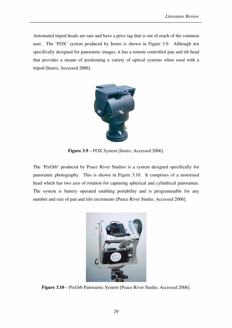
Automated tripod heads are rare and have a price tag that is out of reach of the common
user. The ‘FOX’ system produced by Instro is shown in Figure 3.9. Although not
specifically designed for panoramic images, it has a remote controlled pan and tilt head
that provides a means of positioning a variety of optical systems when used with a
tripod [Instro, Accessed 2006].
Figure 3.9 – FOX System [Instro, Accessed 2006].
The ‘PixOrb’ produced by Peace River Studios is a system designed specifically for
panoramic photography. This is shown in Figure 3.10. It comprises of a motorised
head which has two axis of rotation for capturing spherical and cylindrical panoramas.
The system is battery operated enabling portability and is programmable for any
number and size of pan and tilts increments [Peace River Studio, Accessed 2006].
Figure 3.10 – PixOrb Panoramic System [Peace River Studio, Accessed 2006].

Literature Review
30
3.4.3.3 Video cameras
The use of video cameras in place of digital cameras is possible but not without its
drawbacks. The problem lies with the resolution in today’s commercially available
video cameras. Currently, the Digital Video (DV) format offers a resolution of 720 ×
480 pixel. Even with the emerging high definition camcorder offering a resolution of
1440 × 1080 pixels, it does not come close to digital cameras in terms of the resolutions
of the images.
Studies exploring the use of video cameras in constructing panoramic images of real
world scenes have been carried out including attempts to automate the process. Chen
and his team were able to construct panoramas by panning a video camera in a scene
and through software, automatically select the essential frames and stitch them together
to produce the resultant panorama [Chen, 1998]. However, the problems with
resolution still holds true and therefore video cameras is not a viable option in scenes
where high quality images are required.
3.4.3.4 Panoramic Cameras
Panoramic cameras are designed solely for the purpose of capturing a panorama.
Therefore there are no unnecessary functions of the camera and setup is kept simple.
The use of panoramic cameras has the advantages of enabling the acquisition of
panoramic images and the creation of panorama easier [Huang, 1997]. An example of a
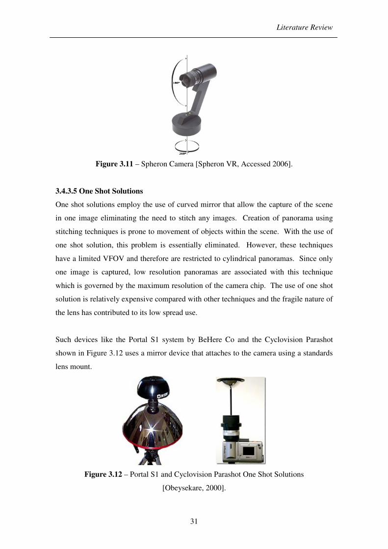
panoramic camera system is the Spheron camera shown in Figure 3.11 which is
produced by a German based company [Spheron VR, Accessed 2006]. This particular
camera has the ability to capture a scene with a contrast range of up to 26 aperture stops
[Jacob, 2004] allowing dark or bright areas within the scene to be seen clearly.
The system possesses a motor that rotates the camera around its vertical axis while the
CCD sensor samples the scene, strip by vertical strip. The images are sent direct to the
computer via Universal Serial Bus (USB) and are displayed in real time. This camera
has the capability of capturing a 360° by 180° panoramic image without the need to
stitch multiple images. However, the substantial cost associated with the equipment
puts this out of reach of most users.
Literature Review
31
Figure 3.11 – Spheron Camera [Spheron VR, Accessed 2006].
3.4.3.5 One Shot Solutions
One shot solutions employ the use of curved mirror that allow the capture of the scene
in one image eliminating the need to stitch any images. Creation of panorama using
stitching techniques is prone to movement of objects within the scene. With the use of
one shot solution, this problem is essentially eliminated. However, these techniques
have a limited VFOV and therefore are restricted to cylindrical panoramas. Since only
one image is captured, low resolution panoramas are associated with this technique
which is governed by the maximum resolution of the camera chip. The use of one shot
solution is relatively expensive compared with other techniques and the fragile nature of
the lens has contributed to its low spread use.
Such devices like the Portal S1 system by BeHere Co and the Cyclovision Parashot
shown in Figure 3.12 uses a mirror device that attaches to the camera using a standards
lens mount.
Figure 3.12 – Portal S1 and Cyclovision Parashot One Shot Solutions
[Obeysekare, 2000].

Literature Review
32
The lens provides a horizontal field of view (HFOV) of 360° and VFOV of 100° and
105° respectively. Using software provided by the vendor, the donut shaped image
generated from the lens can be unwrapped to a seamless panorama [Obeysekare, 2000].
3.4.4 Stitching Software
Following the capture process, application of stitching software stitches the individual
images together to produce a seamless panorama. Although the software itself is not a
component of the thesis, its application is nevertheless an important step in creating the
resultant panorama from the images acquired through the proposed imaging system.
There is a vast number of commercially available panoramic stitching software.
Although the capabilities and ease of use of each software may vary somewhat, they
essentially perform the same basic task. However, a few of the software are more
developed and possess additional features that aim to enhance the overall panorama
experience. In order to determine the most suitable stitching software to employ in the
thesis, careful consideration must be given to the needs of the images and the type of
output panorama and whether the software can fulfil these requirements. The software
must have the ability to:
• Output QuickTime Virtual Reality (QTVR) format.
• Create Single-Row panorama.
• Create Multi-row panorama.
• Create Cylindrical panorama.
• Create Spherical or Cubic panorama.
• Create Hotspots on the resultant panorama.
• Support a wide range of cameras.
• Support wide range of image formats.
• Support high resolution input images.
Following a series of trials with a variety of stitching software, it was concluded that
Realviz Stitcher provided ease of use and offered the required features that was sought

Literature Review
33
after [Stitcher, 2003]. Subsequent panoramas created within the thesis will thus employ
the use of Realviz Stitcher.
3.4.5 Displaying of the Panorama
There are a number of commercially available software’s on the market known as
‘viewers’ with the sole purpose of displaying the stitched panoramas. This provides the
interface through which the user gains an immersive and interactive experience.
Viewed by itself, the panoramic image appears distorted, but through the viewer
software, the distortion is automatically corrected at runtime [Apple Computer, 2005].
A pioneer of the IBVR approach in a commercial setting is Apple’s QTVR player.
Other platforms that have emerged as a competing alternative to QTVR have included
PTViewer and Java-based players. These differ in terms of their quality and
performance [IQTVRA, Accessed 2006]. In order to be able to open the various viewer
formats, their corresponding plug-in must be installed. QTVR is the leading panoramic
platform and offers superior quality and excellent performance [IQTVRA, Accessed
2006]. For these reasons, the thesis aims to utilise the QTVR platform for displaying
panoramas.
Built on top of Apple Computer’s QuickTime (QT) digital multimedia framework,
QTVR extends its interactive capabilities by creating an immersive user experience that
simulates 3D scenes and objects [Apple Computer, 2005]. QTVR is a cross platform
player that runs on both Macintosh and Windows. The capabilities of QT have been
extended through the addition of new types of tracks that have been added to the
existing architecture. Figure 3.13 illustrates the structure of the tracks present in a
QTVR panoramic movie.
Figure 3.13 – QTVR Structure.

Literature Review
34
The QTVR user interface controller allows users to navigate and explore the panorama.
This component is stored in the QTVR extension and is loaded automatically whenever
an application with QTVR movie requires it. Figure 3.14 shows an example of the
user’s interface which controls the panning motion of the panorama.
Figure 3.14 – QTVR User Interface.
The QTVR user controller provides an easy to use interface to explore a QTVR scene.
These are:
• A Back Button – Allows the user to return to the previous node. This button
is enabled only for multimode movies.
• A Zoom-Out Button – Allows the user to zoom out causing the field of view
of the displayed node to increase. This gives the illusion that the panorama is
moving away from the viewer.
• A Zoom-In Button – In contrast to the zoom out button, the user can zoom in.
This causes the field of view of the displayed node to decrease with the
panorama appearing to move toward the viewer.
• A Hot Spot Display Button – Pressing the hot spot display button highlights
the visible hot spots.

Literature Review
35
3.4.6 Virtual Tour
A panorama consists of a view from a single position (or viewpoint) which is defined as
a node. A virtual tour contains a single scene which is a collection of one or more
nodes. When a virtual scene contains more than one node, the illusion of movement
through the scene can be created by jumping from one node to another. In order to
preserve continuity of motion, the view direction needs to be maintained when jumping
to an adjacent location [Apple Computer, 2005]. A distance of about two metres
between the grid points gives a very good spatial impression [Cuntz, 2002].
A multiple node virtual tour allows movement from one node to another through a link
between the source and destination nodes. The link defined as a ‘hot spot’ is
graphically represented on the source node. When clicked, the action is performed and
moves the user from one node in a scene to another node. However other types of hot
spot are available which perform another action and expands the capabilities of a virtual
scene.
Hot spots are areas in a panorama or object movie that link to a node, file or URL. Each
hot spot contains all information about the destination action, and the corresponding
region on the panoramic image [Chiang, 1997]. This feature enables other material
such as maps, still photographs, video footage, fingerprints, tyre prints to be
incorporated into the virtual scene. For example, the location where the prints were
found can be easily related to the scene and displayed by activation of the hot spots.
Hot Spots in QTVR movies extend the interaction between the viewer and the QTVR
scene, helping to make this virtual experience more real. “Going beyond the basic
dragging up or down, left or right while standing here, hot spots are the magic portals
that link you from this movie here to another movie there” [Kitchens, 1998].
3.4.7 Current Areas of Use
Originally used in areas that were deemed too hazardous for humans, such as oil rigs,
panoramic technology has generated a great deal of interest within many different
industries. Its application strives to increase productivity and provide an extra level of
interactivity for consumers.

Literature Review
36
Some of the industries at the forefront in the application of panoramic technology have
been real estate, travel agents and museums [Kitchens, 1998]. The technology gives
potential consumers the ability to visit remote locations over the web and experience
what the location has to offer beforehand. Education can also benefit from such
technology by allowing students to visit an important location relevant to their lesson.
Teachers report that students become more interested in academic content after a real or
virtual field trip that brings the subject matter to life and gives them a lifelike
experience [Benton, 2002].
The benefits of panorama are not limited to the commercial market. In conjunction with
the sheriff’s Safe Schools Unit and local school districts, panoramas are being used to
build virtual school campuses that public safety planners can use for emergency and
disaster planning [Panoscan, Accessed 2006]. In addition, panoramas have emerged in
computer games such as ‘Crime Scene Investigator’, where it involves navigation
through VEs and solving puzzle [UBISoft, Accessed 2006]. The application of
panoramic technology within the area of law enforcement is relatively novel in
comparison to the other industries but commercial products are now emerging that aim
to fill this niche. These will be discussed further in section (3.9).
3.5 Visual Aids
The use of the expert witness has become prevalent over the years; from high profile
cases such as murders to medical malpractices. The ability to portray evidence in a
logical manner remains a difficult task and all too often a jury must form a mental
image of the crime scene through photographs, drawings and verbal testimony
[McCracken, 1999]. While these remain the standard, they pose numerous questions to
the effectiveness in communicating to the jury. Evidence is meaningless if it cannot be
conveyed effectively. Lederer says “Communication is at the heart of litigation;
everything else is secondary” [Lederer, 1994b].
Krieger notes “the value of demonstrative evidence to help jurors understand complex
issues has long been recognized by experienced trial lawyers [Krieger, 1992]. Studies
have shown that jurors are often left confused, bored and even frustrated when
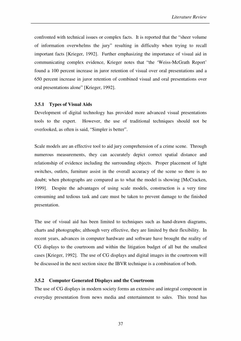
Literature Review
37
confronted with technical issues or complex facts. It is reported that the “sheer volume
of information overwhelms the jury” resulting in difficulty when trying to recall
important facts [Krieger, 1992]. Further emphasizing the importance of visual aid in
communicating complex evidence, Krieger notes that “the ‘Weiss-McGrath Report’
found a 100 percent increase in juror retention of visual over oral presentations and a
650 percent increase in juror retention of combined visual and oral presentations over
oral presentations alone” [Krieger, 1992].
3.5.1 Types of Visual Aids
Development of digital technology has provided more advanced visual presentations
tools to the expert. However, the use of traditional techniques should not be
overlooked, as often is said, “Simpler is better”.
Scale models are an effective tool to aid jury comprehension of a crime scene. Through
numerous measurements, they can accurately depict correct spatial distance and
relationship of evidence including the surrounding objects. Proper placement of light
switches, outlets, furniture assist in the overall accuracy of the scene so there is no
doubt; when photographs are compared as to what the model is showing [McCracken,
1999]. Despite the advantages of using scale models, construction is a very time
consuming and tedious task and care must be taken to prevent damage to the finished
presentation.
The use of visual aid has been limited to techniques such as hand-drawn diagrams,
charts and photographs; although very effective, they are limited by their flexibility. In
recent years, advances in computer hardware and software have brought the reality of
CG displays to the courtroom and within the litigation budget of all but the smallest
cases [Krieger, 1992]. The use of CG displays and digital images in the courtroom will
be discussed in the next section since the IBVR technique is a combination of both.
3.5.2 Computer Generated Displays and the Courtroom
The use of CG displays in modern society forms an extensive and integral component in
everyday presentation from news media and entertainment to sales. This trend has

Literature Review
38
transferred over to the law enforcement community showing real progress and gradual
recognition within the field.
As a tool, computer graphics in the courtroom is an excellent means to convey complex
information in an accessible and easily understood, visual manner [Schofield, 2000].
As Muir expresses about CG displays “they offer a bridge for the technical community
to communicate complex issues to a lay audience” [O’Flaherty, 1996].
Beneficial use of CG display in the courtroom does not stop at just a way of presenting
pleasant pictures to the jury; it can often communicate at more than one level with the
jury from the initial presentation and beyond. There are three main benefits associated
with its use in the courtroom [O’Flaherty, 1996]. Foremost is the ability of CG display
to provide an effective means of conveying evidence to aid jury and judge
understanding. Presenting complex information in such a manner allows for quick and
easy comprehension of the evidence, thus saving time and money. The second benefits
of CG involve the archiving of evidence; allowing all case related information to be
stored on a single DVD. This allows quick accessibility, eliminating the need for
numerous boxes of paper. The third benefit associated with CG display is the
persuasive nature of such technology which will be discussed further in subsection
(3.5.2.3).
The US courts are at the forefront in the use of CG evidence. There have been a vast
number of cases involving the use of CG in the courtroom which has demonstrated the
overwhelming advantage of this technology [Schofield, 2000]. In contrast, the
emergence of CG evidence in UK courts is relatively new. Widespread application of
CG display technology in most other industries along with the identification of the
potentially important role of IT in future justice system have been noted in the Woolf
report “Access to Justice” [Narayana, 2001]. Within the England and Wales legal
system, the Woolf Report documents an increase in use and promotion of IT. A study
by the American Bar Association in 1992 reported that in the US, “13 percent of
medium-sized law firms have used computer animation in cases, and that 45 percent of
them planned to use it in the future” [Krieger, 1992]. This figure will undoubtedly be

Literature Review
39
far greater in today’s US court. This helps demonstrate that the US has recognised the
potential of CG evidence in the courtroom far earlier than the UK and as such are
pioneers in this field. Reference to relevant case law from the US can aid the
development of CG evidence in the UK’s courtroom by providing essential information
regarding admissibility requirements and potential opposition. This thesis will explore
the use of CG evidence in both the US and UK courtrooms and some of the problems
faced.
3.5.2.1 USA
The majority of CG evidence in the US has been limited to civil cases such as personal
injury, product liability and patent infringement [Noond, 2002]. On August 2nd, 1985,
legal history was made with the first major use of CG evidence in court. All one
hundred and twenty eight passengers, eight crew members, and one person on the
ground died as a result of Delta flight 191 crashing on landing during violent winds
[Selbak, 1994]. A fourteen month legal battle followed between Delta airline and the
US government, over who would pay the $150 million to $200 million worth of claims
for wrongful death and loss of aircraft. Delta airlines sought to place blame for the
crash on air traffic controllers [Krieger, 1992]. The US government introduced to the
jury a CG presentation as a means of explaining the details of each item of evidence and
key findings. Subsequently, the US government prevailed in the case. The case marked
a pivotal point for the use of CG evidence and it encouraged wider acceptance of the
technology by other judges and courts [Selbak, 1994].
Another successful use of CG evidence involved the highly publicised ‘Snoop Doggy
Dogg’ trial where gangster rapper Calvin Broadus (aka ‘Snoop Doggy Dogg’) and his
former bodyguard, McKinley Lee were acquitted of killing a former rival gang member,
Philip Woldemariam. Prosecutors claimed that McKinley, who was seated in the
passenger’s seat of Broadus’s jeep, signalled for Woldemariam to approach and then
reached for his gun and shot him in the back twice as he attempted to escape [D’Angelo,
1998]. However, the defence disputed that the shooting was an act of self-defence and
that Woldemariam had pulled a handgun and shot at the vehicle.

Literature Review
40
The jury was left with deciding between two accounts of what may have transpired.
With considerable amount of funds at their disposal, the defence utilised sophisticated
CG illustrations in support of its self-defence theory. Complex evidence, which
normally would require numerous expert witnesses and hours of testimony, was easily
presented to the jury in the form of a brief 3D computer animated video [D’Angelo,
1998]. Consistent with the defence’s self-defence theory, the CG display was able to
show the trajectories of the two bullets including their corresponding entry and exit
point. Through slow motion images, the display conveyed that the force and angle of
the first shot on the victim’s body rotated him slightly, causing the second shot to enter
his back. The jury acquitted the defendant on the charges of 1st and 2nd degree murder
[Girvan, 2001b].
The first USA case to allow VR evidence was Stephenson v Honda Motors Ltd., 1992
Case No. 81067 in which the evidence concerned riding a motorbike across difficult
terrain. The evidence was allowed because it was argued that while 2D photographs
and videos would certainly help the jury to understand the terrain, a 3D view would be
more realistic. The court allowed the evidence, agreeing that this view was more
informative, relevant, and probative [Girvan, 2001b].
3.5.2.2 UK
The use of computer technology has already been well-established in the US; yet it
remains in its infancy within the UK. Explanation for this slow development has been
quoted which includes “lack of skills, distrust about the use of computers and deficient
technology in courtroom to deal with such technology” [Lederer, 1994b]. There has
however, been an increasing use of this technology in recent times and a few pivotal
cases which are changing the ways in which we view this technology within the UK.
In September 1994, the Oxford Crown Court was host to the first instance of CG
displays within the UK involving the case of R v Wharton. Prosecuted by the Serious
Fraud Office, the defendant was convicted of fraudulent trading. During the course of
the hearing, over a hundred CG displays were shown to illustrate some transaction
sequence [Horten, 1994].

Literature Review
41
The case of R v Ore in November 1998 at Birmingham Crown Court saw the early use
of CG display in front of a jury [Girvan, 2001]. In this case the defendant was charged
with causing death by dangerous driving. Called by the prosecution, police constable
(PC) Mike Doyle of the West Midlands Police Crash Investigation and Training Unit
was requested to give evidence. As a part of his evidence he produced and displayed by
means of a video, a 15 second computer simulation that he had created using
Autodesk’s 3D Studio software. Based upon information and figures obtained at the
crash site, the reconstruction showed the sequence of events that transpired between the
defendant and victim’s vehicles; noting the position of the vehicles prior to, during and
following collision. Despite the use of such technology, the defendant was acquitted of
the offence [Girvan, 2001]. Since then a number of CG displays have been admitted to
UK courtrooms [Schofield, 2002].
The 1999 West Midlands Walsall Coroner’s inquest saw the use of CG evidence to help
establish the events that led up to the death of two motorcyclists. Visualisation of how
the deaths occurred was made possible by showing how they collided with a vehicle
that pulled out across their path at a junction. The interactive nature of the presentation
allowed for key moments to be stopped in court and discussed before processing
[Noond, 2002].
One of the most extensive uses of digital technology in the UK courts’ was presented
for the August 2002 Soham murders. This highly publicised trial of Ian Huntley in the
murders of Holly Wells and Jessica Chapman involved the presentation of complex
forensic evidence. Utilising the full resources of the imaging unit of West Yorkshire
Police, a unique digital video disc (DVD) presentation was put together for trial
encompassing all relevant case material; everything from the images and video
interviews to a simple witness statement. This is thought to be the first for a UK court
case [Gower, 2004]. The presentation package included a series of 3D reconstructions,
showing the Soham village, the last known route the girls had taken and exactly how
Ian Huntley might have tried to conceal the girls’ partially burned clothes in the bin at
the school [Morris, 2003]. Use of complete set of 360 degree panoramas provided the

Literature Review
42
jury with views of all the major scenes in the investigation [Gower, 2004].
Subsequently, Ian Huntley was found guilty on both counts of murder.
This type of presentation was praised by numerous individuals including Sir Ronnie
Flanagan; Chief Constable of both the Police Service of Northern Ireland and Royal
Ulster Constabulary and Ken Macdonoald QC; Director of public prosecution. Sir
Ronnie said “using the technology represented a very significant saving of time and
enabled everyone in the court fully to appreciate all aspects of the prosecution’s case”
[Gower, 2004]. Mr Peter Burton, manager of the imaging unit said “the alternative to
using a single DVD like in the Soham case would have been a trial with a slow trickle
of paperwork smothering the courtroom” [Gower, 2004].
3.5.2.3 Persuasive Impact of Computer Images
Computer displays as an instrument of persuasion should not be underestimated. The
inherent dangers associated with the use of computer images are the impact that they
can have on the jury. Jury’s often takes the view that computers are superior and never
lie. The impact that CG displays impart on the viewer gives rise to a significant
potential for misuse and prejudice.
The credibility that jurors place on computers is founded from Television shows such as
Crime Scene Investigator (CSI) which Michael Gorn, a forensic scientist says “has
given people unrealistic expectation of what can be performed and the time frame in
which this can be achieved” [Hempel, 2003]. Calling this the “CSI effect”, the
increasing role of computer animations in these types of Television shows create an
almost “built-in credibility” in the minds of jurors who view it at trial [D’Angelo,
1998]. In the Supreme Court of New York in the case of McHugh, it was found that
computers were merely “a mechanical tool receiving information and acting on
instructions at lightning speed in the presentation of factual evidence”. This statement
is a misconception and gives rise to believe that all computer animations are true factual
statements. It encourages juror to surrender their role in factual determinations and
allow the computer to resolve the factual disputes in the case; essentially placing CG
evidence as the absolute conclusion [Selbak, 1994].
Literature Review
43
This biased nature of CG evidence is evident more so in cases where only one of the
legal parties uses the technology, because it means that one side of the case can be very
persuasive. Out of 858 cases in the US where one party used animations, all but 15
settled out of court. Of the 15 that went to court the side using the animation always
won [O’Flaherty, 1996]. Reasons cited for the lack of use is down to cost. While the
cost associated with creation of CG displays has become more affordable in recent
years, it still remains relatively expensive and therefore out of reach of most but the
wealthier parities.
This bias towards the parties that use CG evidence has led at least one court to preclude
its use. In the case of Racz V R.T.Merryman Trucking, Inc, the defendant’s CG
recreation of the accident was precluded from the trails on the grounds that unfair
prejudice to the plaintiff. The court recited the old adage, “seeing is believing,”
articulating that the jury might give undue weight to a computer recreation and may lead
them to accept the data and expert opinion as the definitive conclusion [Selbak, 1994].
With the exposure of CG displays on television and in the movies, jurors have become
accustomed to receiving information through this medium. Not only is this form of
presenting information a more stimulating method, its psychological impact on juries
extend far beyond that which can be achieved purely by verbal presentations. Studies
have shown that information retention is affected by the medium through which the
information is relayed. It was found that sixty-five percent of jurors that received
information through a combination of oral and visual evidence could recall the evidence
presented three days later. Where only oral evidence was presented, only 10 percent of
this was retained by the jurors [Selbak, 1994]. In another series of studies, the Crash
Investigation and Training Unit (CITU) in the UK presented three separate groups with
a series of accident information. The first group received the information in the form of
a textual description; a second group was shown images and the third group a
combination of both text and images. The group that performed the worst with the most
errors was group one, which received only descriptive information, whereas the group
that was shown both text and images performed the best (Doyle, 1999) [Schofield,
2000]. Berkoff says “it is clear that visual presentation is more effective than verbal

Literature Review
44
communication, and that verbal communication is most effective when coupled with a
visual presentation” [O’Flaherty, 1996]. Essentially humans have a pictorial memory
which far surpasses our verbal memory. Although, the studies have shown that the
most important method of communicating technical information is through
visualisation, there are many questions which remain unanswered concerning the impact
of such visualisation on the jury.
The emotive nature of some cases can introduce bias into the court especially when the
crimes have involved considerable violence. Therefore, in order to remove this bias,
images and animations should where possible exclude any contents of a visceral nature.
Images of victims should be replaced with human figures to avoid shock to the viewer.
Such caution in the use CG displays has been shown in the case of People V Mitchell.
Convicted for the murder of his brother despite claims that he acted in self-defence, the
prosecution used CG illustration to show that it was not possible for threatening
gestures made by the victim to be seen behind the wall that the defendant stood. Upon
defence counsel’s objections, the CG display was ordered to be changed several times;
ultimately replacing the human like figure with geometric shape to avoid the risk that
the jury might assume as proven fact the position of deceased’s hands in the illustration
[Selbak, 1994]. Another high profile case where bias was an issue was the O.J.
Simpson case. Desire to make the CG evidence as realistic as possible, the true skin
colour was shown. However, this was decided too be too suggestive in that the person
committing the crime was portrayed as being black and may bring unfair bias to the
case [Narayana, 2001].
The interactive nature of CG displays is a major advantage of this type of presentation.
However, misuse of this can introduce bias in the proceedings. This was shown in the
Rodney King murder case where the video portraying the beating was played slowly to
de-emphasise the brutality of the event. By speeding up, slowing down or showing the
animation from a particular viewpoint, the court may be led to believe something
happened in a way that may be slightly or even greatly removed from the facts
[Narayana, 2001].

Literature Review
45
There is no doubt that CG displays are a powerful tool of persuasion in the armoury of
any technologically adept litigator who is prepared to use them. Nevertheless, some
commentators have expressed considerable unease about the use of such technology in
the courtroom. The consequences of misuse of CG displays cannot be underestimated
particularly in the context of a criminal trial where as one writer has noted: “Rather than
an award or loss of money judgement, the defendant in a criminal prosecution is subject
to a loss of liberty” (Bardelli, 1994) [O’Flaherty, 1996].
Lighting conditions within a scene has always presented a problem to SOCO’s when
recording a scene as it was found. This can directly affect the way that a viewer
perceives a scene presenting a possibility of bias to the viewer. In scenes where there is
low level ambient lighting, an optical system can experience difficulties in capturing the
details of a scene and vital information may be lost. However, the introduction of
artificial lighting such as a flash or external lighting can also be problematic; essentially
changing the conditions of the scene by the addition of shadows or the alterations of
colour temperature. This can be used as persuasive tool causing viewers to associate a
scene such as a dark alley with a warmer gentle scene through manipulation of lighting
and colour settings. Therefore, care must be taken to avoid unnecessary tampering of
lighting conditions within a scene.
3.5.2.4 Manipulation or Enhancement
During the course of a criminal proceeding it may be necessary to utilise computer
techniques to enhance an image in order to increase its clarity. However, due to the
ease with which digital images can be edited and manipulated with commercially
available software packages, there is much concern regarding its use within the law
enforcement community. Herb Blitzer, executive director of the Institute for Forensic
Imaging says “Its widespread use makes digital imaging suspect in the courtroom, but
such images are really no more suspect than any image shown in a modern courtroom”
[Biehl, 1999]. The use of digital images for evidential purposes opens up many
questions regarding its use for evidential purposes. What represents justifiable
enhancement? Does this differ from manipulation which might have, or be perceived to
have, malicious intent, and where can the distinction be drawn? [House of Lords, 1998].

Literature Review
46
Image enhancement is done solely with the intent to clarify existing information;
nothing is added to the image. Generally, image enhancement techniques have direct
counterparts in traditional silver-based darkrooms. These include brightness and
contrast adjustment, colour balancing, cropping, and dodging and burning which are
acceptable forensic techniques [SWGIT, 2003]. Non-traditional image enhancement
techniques that are limited to computers such as colour processing, linear filtering,
nonlinear contrast adjustments, pattern noise reduction, and random noise reduction are
only recently being applied within the forensic environment [SWGIT, 2003].
Manipulation, on the other hand is defined as “to change by artful or unfair means so as
to serve one’s purpose.” [Azcarate, 2000]. Any alterations which affect the image data,
no matter how innocuous, should be treated with caution [House of Lords, 1998].
It is not always immediately clear what constitutes enhancement and what may verge
into the area of improper manipulation that can distort or introduce information [Russ,
2001]. The person submitting the images as evidence must explain what the image is a
picture of, why it is relevant, how it was acquired, how it came to be in court and what
it implies.” [Biehl, 1999]. Acceptance of enhanced images ultimately falls on the
judge’s discretion. In the double homicide case of State of California v Phillip Lee
Jackson, the defence requested for a Frye hearing † on the admissibility on the digitally
enhanced fingerprint image. However, the court ruled this unnecessary on the argument
that digital processing is a readily accepted practice in forensics and that new
information was not added to the image [Staggs, 2001].
† Frye Hearing – Used in the U.S, the Frye hearing examines whether the evidence
being submitted has gained general acceptance in the particular field in which it
belongs.
Literature Review
47
The relatively new nature of digital imaging within the legal system combined with
increase exposure in the form of television shows has allowed the potential for claims of
image manipulation to be quite effective; especially when the chain of custody is poorly
documented [Berg, 2000]. Developing and following Standard Operating Procedures
(SOP) to document the whole process of enhancement ensures that each of the steps are
logged so that the results can be duplicated if needed and should preclude the question
of whether a photograph was digitally enhanced with the intent to falsify information
[Advanced Imaging and Analysis, 1999].
An issue of manipulation was raised in a 1995 murder trail in Seattle. A digitally
enhanced palm print was the only conclusive evidence that tied the defendant, Eric
Hayden to the crime scene. Questions regarding the ability of the computer to make
arbitrary changes to an image without the knowledge or consent of the operator were
raised. The defence also implied that deliberate changes could have been made to the
image, by the operator, which resulted in a false identification [Berg, 2000].
3.6 Admissibility of Computer-Generated Evidence in the Courtroom
The merging of traditional forensic science with computers has created its own set of
complications within the legal system. Although a digital photograph may be
cosmetically identical to a conventional photograph, its very qualities inherent in digital
data present an entirely different species of evidence [McCarvel, 1995].
Exiting rules of evidence are constantly being challenged by the applications of novel
technology such as digital photography. All forms of evidence can raise questions of
authenticity; digital images are not unique in this respect [House of Lords, 1998]. The
fact that digital photographs are more easily altered than film-based photograph is
usually cited [Staggs, 2003]. With the growing awareness to the ease by which a digital
image can be altered, courts will have to establish procedures to assure the accuracy and
integrity of digital visual evidence admitted into legal proceedings. It is inevitable there
will be challenges to its admissibility in court and new guidelines will have to be drawn
up to address the issues. The laws that deal with the admissibility of digital displays as
Literature Review
48
evidence differ somewhat from country to country. Due to the extensive use in the US,
the laws governing the use of digital images are more developed than then UK.
3.6.1 USA
In order to prevent potential bias and unfairness, CG displays must pass through a set of
criteria before being admitted as evidence in US courts. Evidence can be of two types:
demonstrative or substantive. Demonstrative evidence is used for its explanatory value
and serves only as a visual aid. Substantive evidence on the other hand possesses
probative value that is used to prove a fact. Depending on the type of evidence, a set of
criteria must be met for its admissibility in court. Ultimately it falls to the trial judge’s
discretion to decide upon whether the distinction of the type of evidence made by the
counsels submitting the evidence is correct.
3.6.1.1 Admissibility of Demonstrative Evidence
Demonstrative evidence is used only to illustrate an expert’s testimony and is
considered to have no probative value. The standard test for its admissibility is
relevancy. Council admitting demonstrative evidence must show that the evidence has
a logical tendency to make the existence of any fact of consequence to the action more
or less probable than without the evidence [Bardelli, 1994].
A principal case concerning the admissibility of CG evidence as demonstrative evidence
is the case of People v. McHugh. The defendant sought to introduce a computer re-
enactment illustrating his alternative theory of the car crash incident. The court found
the CG display to be admissible on the theory that it was more akin to a chart or
diagram than scientific evidence, thus the stringent pre-trial hearing that is required of
substantive evidence was not necessary [Borelli, 1996]. Whether a diagram is hand
drawn or mechanically drawn by means of a computer is of no importance [Bardelli,
1994].

Literature Review
49
3.6.1.2 Admissibility of Substantive Evidence
Due to nature of substantive evidence, they are subject to more stringent standards and
greater scrutiny than the evidence submitted solely for demonstrative purposes. Both
Frye and the Federal Rules of Evidence standards apply to substantive evidence.
3.6.1.2.1 The Frye Test
In 1923, a landmark decision in the case of Frye v. United States defined the basic
prerequisite for admitting scientific evidence. The case considered the use of a systolic
blood pressure analysis, the precursor to the polygraph test, in a criminal case.
Although the attempt to admit this technique failed, the principle on the general
scientific acceptance articulated during the course of the case opened up the door for
numerous admittance of scientific evidence within the US court system [Matson, 2004].
The principle of the ‘Frye test’, examines whether the evidence being submitted has
“gained general acceptance in the particular field in which it belongs” [Berg, 2000].
However, it is not enough simply for a few experts to approve of a scientific technique.
Under Frye, the technique must be generally accepted by the relevant scientific
community [Bardelli, 1994]. This standard governed the admissibility of scientific
evidence over the next seventy years.
There have been a few cases that refer specifically to the challenges made to the use of
digital images as evidence. The case of State of Florida v Victor Ryes where the
defence requested a Frye hearing on the admissibility of a digital image of a palm print
that was put through a series of enhancement techniques. The state presented testimony
of two further experts to demonstrate that the use of digital imaging to enhance a latent
print is not new, and that it is accepted within the relevant forensic community. This is
supported by the International Association for Identification (IAI) which states “that
electronic/digital imaging is a scientifically valid and proven technology for recording,
enhancing, and printing images and like conventional silver-halide based photography,
it is accepted by professional commercial photographers, law enforcement
photographers, and identification community” [Knoerlein, Accessed 2006].

Literature Review
50
Despite the wide use of the ‘Frye test’, there has been much criticism of the strictness of
this standard and the difficulty in defining the ‘relevant scientific community’ to which
the technique belongs as many scientific application do not fall squarely within any one
scientific field. This has let many courts to shift away from its use.
3.6.1.2.2 Federal Rules of Evidence
Although the Frye test standard is still applicable in about half of the states, another rule
started to take precedent in 1993. The civil case of Daubert v. Merrill Dow
Pharmaceuticals, considered claims by the plaintiffs that the ingestion of the
prescription anti-nausea drug Bendectin, widely taken in the 1960s and 1970s by
pregnant women with morning sickness was the cause of children’s serious limb
defects. The court in this case, for the first time, rejected Frye as the sole standard for
the admissibility of scientific evidence, announcing Federal Rules of Evidence (FRE) as
the new standard. Essentially, Frye’s general acceptance test was superseded by the
FRE adoption. Since that time, a number of state courts have also adopted FRE as the
standard they use for determining the admissibility of scientific testimony [Berg, 2000].
The admissibility of scientific evidence through the FRE is concerned with three
requirements: relevancy, authentication and procedural requirements which are finally
decided upon by the trail judge.
The root of the FRE test is its relevancy requirement and under rule 40, states that
relevant evidence is evidence which has “any tendency to make the existence of any fact
that is of consequence to the determination of the action more probable or less probable
than it would be without the evidence” [Bardelli, 1994]. The inclusion of FRE 403
which states “although relevant, evidence may be excluded if its probative value is
substantially outweighed by the danger of unfair prejudice, confusion of the issues, or
misleading the jury, or by considerations of undue delay, waste of time or needless
presentation of cumulative evidence” [Bardelli, 1994]. Once relevancy has been
determined, under the FRE the reliability of the evidence admitted must be determined
by the trial judge.

Literature Review
51
In addition to requirement of relevancy, the FRE requires authenticity standards to be
met. The FRE rule 901(a) simply states that: “The requirement of authentication or
identification as a condition precedent to admissibility is satisfied by evidence sufficient
to support a finding that the matter in question is what its proponent claims” [Bardelli,
1994]. Adhering to this rule with CG in mind, the advocate should be able to explain
the procedures used to input the data, and reveal tests used to assure the accuracy and
reliability of this data.
Under the FRE approach, procedural requirements are also considered. These include:
first, qualification of the expert; second, adequate cross-examination of the expert; third,
careful jury instructions as to evaluation of the expert testimony; and fourth the
exchange of all relevant data before trial [Bardelli, 1994].
3.6.2 UK
Although the application of digital displays has only recently started appearing in UK
courts, relevant case law from the US and other jurisdictions may be referenced for
admissibility requirements [Schofield, 2002]. In the UK, laws governing evidence are
separate in civil and criminal courts. Although, there is no legislation in the UK which
specifically covers the use of digital images as evidence, there exists a significant
portion of the law which deals with technological recording which would equally apply
to digital images.
The rules of evidence of common law jurisdictions exclude certain types of document
such as ‘hearsay’ which are generally not admissible as evidence. However,
information captured through the use of recording devices such as cameras involve no
human intervention and as such is not normally classed as hearsay thus can be admitted
in evidence [House of Lords, 1998].
3.6.2.1 Civil Legislation
In civil litigations, there are no prior requirements which must be met before a
document which includes digital images can be admitted in evidence [House of Lords,
1998]. Section 1 of the Civil Evidence Act 1995 abolishes the hearsay rule for civil
proceedings. It states [Swarb, Accessed 2006]:
Literature Review
52
1) In civil proceedings evidence shall not be excluded on the grounds that it is
hearsay.
2) In this Act –
a. “Hearsay” means a statement otherwise than by a person while giving
oral evidence in the proceedings which is intended as evidence of the
matters stated; and
b. References to hearsay include hearsay of whatever degree.
Section 8 provides that prove of a document can be in the form of a copy, even if the
original is still in existence and that it is irrelevant how number of removes between a
copy and the original [House of Lord, 1998].
The introduction of the Civil Procedure Rules (CPR) has bestowed addition powers to
judges to control the preparation for and during a trial. Section 32(1) of the deals with
the power of court to control evidence, and states [DCA, Accessed 2006]:
1) The court may control the evidence by giving directions as to -
a) the issues on which it requires evidence;
b) the nature of the evidence which it requires to decide those issues; and
c) the way in which the evidence is to be placed before the court.
2) The court may use its power under this rule to exclude evidence that would
otherwise be admissible.
3) The court may limit cross-examination.
3.6.2.2 Criminal Legislation
In criminal cases, computer output is only admissible in evidence where special
conditions are satisfied. These conditions are set out in detail in section 69 of the Police
and Criminal Evidence Act (PACE) 1984. Section 69 states that computer records are
admissible as evidence if they can verify to their accuracy. Specifically, any party
relying on computer evidence has to provide oral or written certification of the
reliability of the computer; stating that either the computer system was at all times

Literature Review
53
operating properly, or that any defect in its operation was not such as to affect the
accuracy of the record [House of Lords, 1998].
Section 69 of PACE provides that [House of Lords, 1998]:
1) In any proceedings, a statement in a document produced by a computer
shall not be admissible as evidence of any fact stated therein unless it is
shown:
(a) That there are no reasonable grounds for believing that the statement
is inaccurate because of improper use of the computer;
(b) That at all times the computer was operating properly, or if not that
any respect in which it was not operating properly or was out of
operation was not such as to affect the production of the document or
the accuracy of its contents; and
(c) That any relevant conditions specified in rules of court under
subsection (2) below are satisfied.
2) Provision may be made by rules of court requiring that in any proceedings where
it is desired to give a statement in evidence by virtue of this section such
information concerning the statement as may be required by the rules shall be
provided in such form and at such time as may be required.
Printout from a computer which records information automatically without human
intervention is admissible as real evidence and therefore involves no question of
hearsay. However, printout where information has been supplied to the computer by a
person it is hearsay but may be admissible under section 23 or 24 of the Criminal
Justice Act 1988. A statement can only be admitted under section 23 or 24 if its maker
had reasonably supposed to have had personal knowledge of the matters dealt with. A
statement in a computer printout which has satisfied the foundation requirements of
section 23 or 24 can only be admitted on satisfaction of the additional requirements
contained in section 69. The object of section 69 is to impose a duty on anyone who
wishes to introduce a document produced by a computer to show that it is safe to rely on

Literature Review
54
that document and it makes no difference whether the computer document has been
produced with or without the input of information provided by the human mind and thus
may or may not be hearsay [Hoey, 1996].
The repeal of section 69 of PACE by The Law Commission stated the impracticality to
“certifying all the intricacies of computer operation and experience showed that most
computer error was either easy to detect immediately or had resulted from human error
in data entry rather than from malfunction”. In the absence of Section 69, a presumption
of proper functioning would be applied to computers [House of Lords, 1998].
3.7 Standard Operating procedures
The concerns associated with the use of digital displays such as the integrity of digital
evidence can largely be addressed by employment of SOP. This will aid the acceptance
and development in the use of digital images.
Failure to establish adequate SOP may render any evidence collected worthless. This
was evident in the March 2004 Madrid bombing on a commuter train which killed 191
people. Spanish authorities submitted to the FBI for analysis a partial latent fingerprints
obtained from plastic bags that contained detonator caps. A comprehensive search
revealed prints that were subsequently linked to Brandon Mayfield [FBI Press Room,
2004]. He was jailed for 17 days after which the case was dropped and he was released
following concerns regarding the accuracy of the identification made by the FBI and
further review was required. It was determined that the FBI identification was based on
substandard quality digital copy images of the original leading to the false identification
of Brandon Mayfield. A senior FBI official said that the use of a copy of the
fingerprint, rather than the original, was allowed by lab guidelines. “It was absolutely
acceptable to examine a digital image,” the official said. But the official said that the
question of how and when copies should be used will be reviewed by the bureau in light
of the Mayfield episode [The New York Times, 2004].
The UK Police Scientific Development Branch (PSDB) published the ‘Digital Imaging
Procedure’ in March 2002 which details the procedures involved in the proper capture,

Literature Review
55
handing, achieving and securing of digital images for law enforcement involved
throughout all stages of the Criminal Justice System. This is intended as a guideline
that individual companies or constabulary can use in order to develop their own SOP.
SOP can be divided into four stages: Preparation, Capture, Protection and use as
illustrated in Figure 3.15.
Figure 3.15 – Recommended Steps for Standard Operating Procedures.
3.7.1 Preparation
The preparation stage of the SOP involves steps to be taken before images are captured.
This involves obtaining relevant authorisation and starting an audit trail at the earliest
opportunity in order to help safeguard the integrity of the images captured. Although,
very much similar to taking notes for the general documentation of the crime scene,
additional information should be included such as [PSDB, 2002]:

Literature Review
56
• The creation and defining of the Original;
• The storage of the Original;
• Any access to the Original;
• Disposal
Another step essential in the preparation stage is to ensure that the operation of any
equipment and software employed is functioning properly. This allows the output
images to avoid question of inaccuracy due to computer error.
3.7.2 Capture
The capture stage covers the capture of images and its transfer onto the chosen medium,
taking into consideration the quality and integrity of the images. Generally digital still
camera can be used in the same ways as conventional cameras. However, due to its
digital nature, they possess a few differences. The image quality of the settings on the
digital camera should be as such to be adequate to the operational requirements rather
than to minimise storage capacity. The ability of digital cameras to delete images
should be addressed. During the course of the investigation, any images taken whether
clear or not should not be deleted without authority. Any deletion of images may result
in legal challenge during any prosecution.
Initial acquisition of image from the digital camera to the removable medium; i.e. flash
card is known as the ‘primary’ image (Figure 3.16). Due to the nature of the storage
medium, the images captured are susceptible to image tampering and should therefore
progress to the protection stage as soon as possible.

Literature Review
57
Figure 3.16 – Defining Stages of Image Transfer.
3.7.3 Protection
The protection stage involves transferring the ‘primary’ images to a non-reusable
medium in order to protect the images and reduce the opportunities for challenges at
court. Non-reusable ‘write once read many times’ (WORM) media such as CDs, DVDs
are ideal, in that once closed the recording on the disc cannot be altered.
Digital technology offers new challenges for authentication and, at the same time,
technology can be employed to meet those concerns [McCarvel, 1995]. The use of
authentication techniques such as watermarking and encryption allow for the reliability
of evidence to be established and aid in detecting any intentional or unintentional
alterations to the images.
3.7.4 Use
The images transferred to the WORM media is defined as the ‘Master’ or ‘Original’
through from which all subsequent working copies are duplicated from. Working copy

Literature Review
58
is the version that will be used for investigation and to assist in the preparation of the
prosecution file (Figure 3.16). Since a copy of a digital image file is a bit for bit
identical copy, the working copy is the same and will have the same evidential weight
[PSDB, 2002]. The Master copy is stored securely and is only viewed upon doubt to
the integrity of the images.
3.8 Technology in the Courtroom
The success of CG displays in the courtrooms will largely depend on its ability to
accommodate such technology. Courtroom and chamber technology encompasses any
technology built into the court that aid in communication and presentation of evidence.
Unless courts are adequately equipped to present the CG displays, there will be little
value in its use. This technological capability has been largely absence in courtroom
but is now beginning to change [Lederer, 1994b].
Leading the way in the advancement in courtroom technology has been the US. US
company such as ‘Doar Litigation Consultancy’ offers expertise in setting up courts
with high-tech visual systems. It is estimated that they have helped equip over 500
courtrooms with technological capability [Doar, Accessed 2006]. Of 1366 courtroom in
US district courts, 363 have laptop computer wiring and 370 have some form of
computer monitor displays for the jury [Wiggins, 2003]. In order to increase the use of
technology, the Judicial Conference of the US in March 1999, approved
recommendation to endorse the use of technologies in the courtroom. Subject to
available funds, recommendation consisted of including video evidence presentation
systems into existing courtrooms [Wiggins, 2003].
Technology for the sake of technology is an inappropriate use and results in waste of
money and human resources. In 1993, saw the unveiling of Courtroom 21, the most
technologically advanced courtroom in the US. This courtroom serves not only as an
international model of integrated mainstream, commercially available technology but
also as an experimental test bed for various techniques [Lederer, 1994b]. Courtroom 21
project provides all that are concerned with courtroom activities with a functional model
courtroom where the technology can be examined and scrutinised and debated in order

Literature Review
59
to determine if the technology meets their needs. The model courtroom is continuing
changing and helps bring these new innovations to the mainstream.
3.9 IBVR and Forensic Science
The use of GBVR within a forensic context has been well documented. However, with
the arrival of IBVR in recent years, the forensic community has begun to realise the
potential of such technology. A need to improve the ability to present complex physical
evidence located at major crimes scenes was recognised by the Queensland Police
Service (QPS) in Australia. In 1997, the Interactive Crime Scene Recording System
(ICSRS) was developed by QPS as an additional tool to aid police investigators
[Morley, 2002]. The procedure involves using a camera mounted tripod adapted for
taking ICSRS images much like the standard camera (single-row) technique outlined in
subsection (3.4.3.1), and capturing a full set of 360 degree photos [Rutledge, Accessed
2006]. These images are then electronically stitched to create a virtual view allowing
viewers to move around the scene at their own pace. At the time of implementing of the
ICSRS, the QPS was the first jurisdiction in Australia to use this technology in the
investigation of crime, and the first at an international level to use the technology in the
courtroom [Morley, 2002]. Application of the ICSRS in court proceedings has been
successful and since its introduction, the ICSRS has been adopted by the South
Australian and New South Wales Police Services [Rutledge, Accessed 2006].
IBVR’s ability to provide a cost effective method of training and assessment has led the
National Institute of Forensic Science together with the combined police services in
Australia to develop ‘After the Fact’ [NIFS, 2002]. This is CD-ROM based, consisting
of a series of interactive multimedia training and assessment programs. Using
panoramic techniques, the program creates a virtual crime scene which allows
investigators to obtain the necessary skills for crime scene investigations without the
necessity for creating expensive and time consuming mock ups of scenes.
A recent emerging system which has the potential to revolutionise the way that law and
forensic communities document crime scenes is the ‘Return to Scene’ (R2S) system.
Created by an Aberdeen based technology company, MaxIMT, in collaboration with
Literature Review
60
Grampian Police, provides a simple yet high quality system for capturing a 360 degree
IBVR scene. This system utilises the latest technology through a Spheron High
Dynamic Range camera (discussed in Chapter 3.4.3.4) which possess a 26 f-stop
dynamic range and captures images with a 50 mega pixel resolution and 48 bit colour
depth per pixel [MaxIMT, Accessed 2006]. This produces a high quality VE with the
ability to enhance areas which are difficult to see, bringing over exposed or under
exposed areas back into view. This is one of the main vantage points of using a
Spheron camera as oppose to a normal digital camera which only allows variation of the
contrast and brightness of the images. Additional differences compared to the use of
normal digital camera lies in the way the images are captured. Instead of capturing a
series of images, the Spheron camera scans vertical strips of the room while rotating.
Through R2S’s unique software application, the VE is then displayed in real time,
eliminating the need to stitch the images together. This highly sophisticated system
provides an additional tool for police and forensic investigators. Due to the high price
associated with each system, it use is limited to only the highest profile cases.
3.10 Summary
This chapter has provided the necessary background knowledge that relates to the main
context of the thesis. By first introducing the three types of crime scene documentation
techniques; notes, photography and sketches employed by today’s law enforcements, it
provided an insight to the area of contribution that the thesis can make. A basic
knowledge of digital photography technology provides an overview of the advantages
that this technology can bring to the law enforcement community. These have to do
primarily with the digital recording of the data, which permits duplication, transmission,
and storage of the image without any degradation of quality. The chapter provided an
in-depth account of the types and methods for creating VEs. The thesis then identified
the current application and acceptance of CG displays within the US and UK including
their admissibility within the courtroom.

Case Studies
61
Chapter 4: CASE STUDIES †
4.1 Introduction
As discussed in Chapter 3, the application of CG displays has been relatively new,
particularly within the UK. The increasing need to communicate complex data in
layman’s language is bringing about a change in the viewpoint of forensic scientist
towards the use of CG displays as a method of presenting evidence. Jurors are easily
confused by technical explanations, placing more credibility upon what they can see and
touch [Berg, 2000].
Communication of forensic data in court using traditional visual aids was considered
inadequate by the forensic scientists, whom sought more effective methods. This
chapter presents four case studies which in collaboration with forensic scientist from
FA, resulted in the construction of CG displays to convey complex forensic information
for use in court. Through these case studies, lessons can be learnt as to the best possible
method of creating an effective CG presentation.
4.2 Case Study 1
This case, headed by Tiernan Coyle from FA, is the first one-to-one (1:1) taping case in
the UK. In collaboration with Thames Valley Police (TVP) force, this case hopes to
serve as a milestone to the potential benefits of the 1:1 taping technique. Originating
from Germany, 1:1 taping has not gained widespread use due to the burden that the
technique places on resources. The area of taping defines the exact position of the
fibres on the surface which indicates the type and extent of the contact that caused the
fibre transfer. “It is unlikely that fibres cluster together in numbers on surfaces by
chance; the relative frequency of their occurrence in the general population at large
becomes far less probative than their distribution on the surface in question” [Coyle,
2004]. Conventional methods of fibre comparison would usually do little more than
provide evidence which was suggestive of contact between two materials. They provide
little, if any, assistance as to the nature and extent of the contact which had occurred.
† Cases undertaken by the author on part of his PhD research.

Case Studies
62
4.2.1 The Case
The body of a deceased man was discovered lying on his back on the lounge floor in his
own house. Subsequent post mortem concluded that the victim had bled to death
through severing of the left common carotid artery and left internal jugular vein.
On arrival of the police, a new technique, 1:1 taping was employed. Although, the
technique generally requires that both the front and back be taped, due to the presence
of wet blood, a decision to tape only the front of the body was made. Seventy six
tapings were taken from the body of the deceased with the position of the strips
recorded by photography. However, two of these tapings could not be assigned to
specific area of the body despite the presence of photographs, thus are not examinable.
Subsequently, a bag containing a red bloodstained hooded top and black tracksuit
bottoms were discovered nine days after the murder by a member of public in the
woods. These were submitted to the laboratory for further analysis. Figure 4.1 presents
photographs of the suspect’s clothes used in the analysis and comparison of the fibres.
Figure 4.1 - Photographs of the Suspect’s Clothing [Coyle, 2002].
Following information received by the police, a suspect was arrested. Although,
initially denying any involvement, the suspect was interviewed five times; his story
changing on each subsequent interview. Due to the mounting evidence against the
suspect, he stated that the clothing must have been stolen from his caravan by someone
and worn to carry out the attack before abandoning it in the woods.
Case Studies
63
4.2.2 Requirements of the Case
Concerns were voiced regarding the best possible way to illustrate the findings of the
fibre evidence in court. Analysis revealed heavy and prolonged contact between the
suspect and victim. In particular, areas of high number of matching fibres on the victim
suggested that the suspect had sat astride the victim’s chest with his weight distributed
to the left hand side while leaning forward; essentially pinning the victim down. It is
the requirement of the presentation to present the conclusion of this fibre evidence in a
clear and logical manner using CG methods.
Displaying this information in the form of tables, would remove the ability to visualise
the patterns that allow the jury to grasp the full details that the 1:1 technique is
exhibiting. Therefore, a graphical representation is required to accurately show the
distribution of fibres on the surface of the victim in relation to the fibres from the
suspects' clothes.
4.2.3 Presentation
Accounting for 3.8% in the world, the UK has 35,807,929 internet users as estimated in
June 2005 [e-consultancy, Accessed 2006]. The decision to utilise web-based
technology results from this familiarity with the internet and its software. This gives a
user friendly platform in which to demonstrate the evidence. The presentation,
consisting of four main sections is linked together using hyperlinks and hotspots,
providing an interactive presentation in which the expert witness can illustrate and
explain the evidence of the case in any order.
The first section as illustrated in Figure 4.2 presents the total number of fibres
transferred from suspect to victim and vice versa. In order to avoid sympathy towards
the victim and therefore bias that can be introduced with the use of scene photographs, a
graphical representation of the victim and suspect are used in this section. The colours
and patterns of clothing worn during the alleged attack are represented as closely as
possible. Total transfer of fibres is represented by a figure and an arrow indicating the
direction of transfer.

Case Studies
64
Figure 4.2 – Transfer of Fibres from Suspect to Victim and Vice Versa.
The second section of the presentation gives a more detailed representation of the fibre
transfer by relating the number of red and black fibres found on each taping to the
position that the taping were placed on the surface of the deceased. Additionally, by
illustrating the red and black fibres separately, it helps demonstrate not only the extent
of the contact but which part of the suspect was in contact. Regions representing the
area that the taping was placed on the body were marked out on the representing image
of the victim and numbered accordingly based on the photographical evidence. The
number of fibres matched to the suspect’s clothing were grouped into several categories,
colour coded and superimposed onto the image accordingly. A darker shade of colour
represents groups with greater number of fibres transferred. By colour coding the
groups of fibres and superimposing onto the image as illustrated in Figure 4.3, a quick
visualisation of the level and area of contact that each piece of clothing of the suspect
had with the victim was made possible.

Case Studies
65
Figure 4.3 – Transfer of Red and Black Fibres onto the Deceased.
To provide an increase sense of accuracy, realism and flexibility, scene photographs
were integrated into the presentation. A series of photographs were chosen to represent
all seventy four tapings. Using colour shape indicators, each significant fibre found on
the tapings are represented by an individual indictor and superimposed onto the scene
photographs in the area that the taping was taken as presented in Figure 4.4.
Figure 4.4 – Representation of Individual Red Fibre Transfer on Scene Photographs.
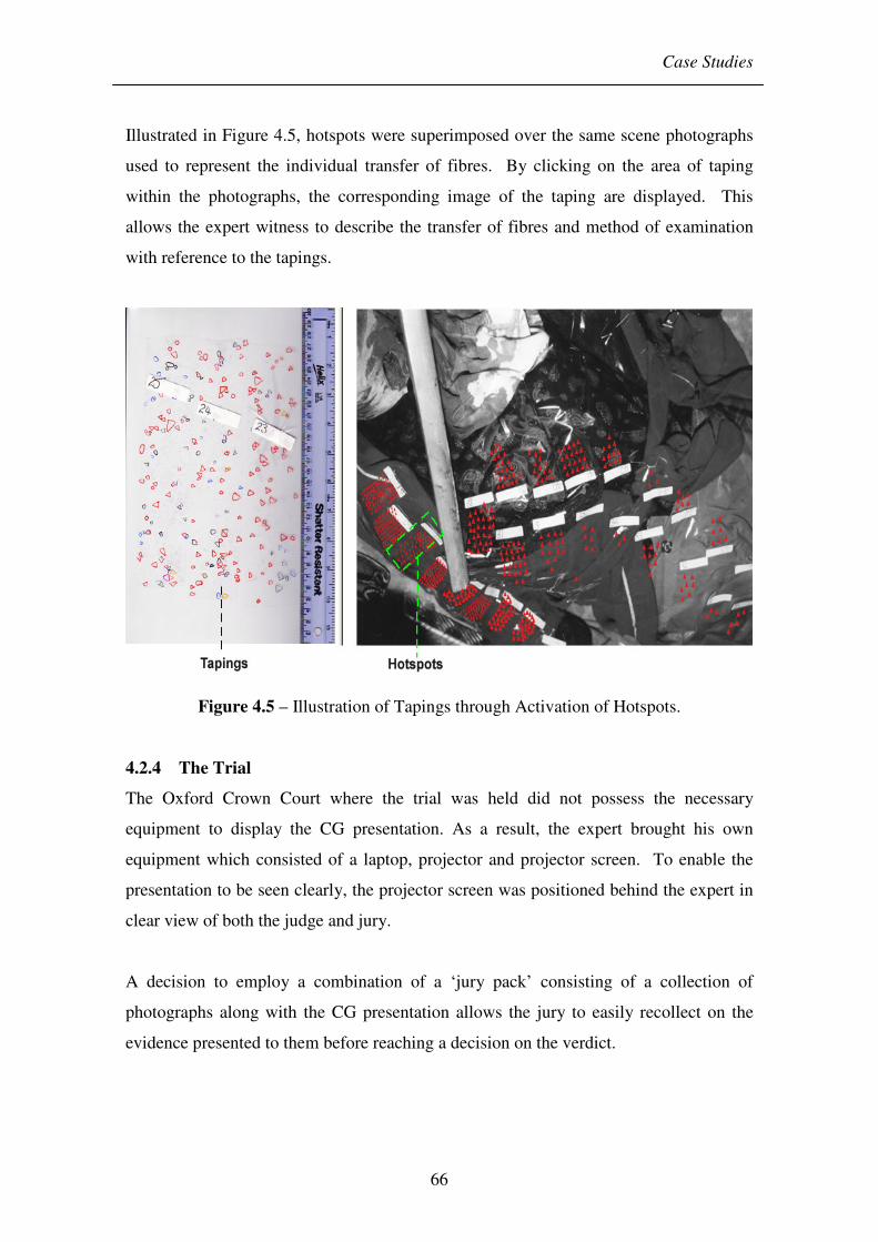
Case Studies
66
Illustrated in Figure 4.5, hotspots were superimposed over the same scene photographs
used to represent the individual transfer of fibres. By clicking on the area of taping
within the photographs, the corresponding image of the taping are displayed. This
allows the expert witness to describe the transfer of fibres and method of examination
with reference to the tapings.
Figure 4.5 – Illustration of Tapings through Activation of Hotspots.
4.2.4 The Trial
The Oxford Crown Court where the trial was held did not possess the necessary
equipment to display the CG presentation. As a result, the expert brought his own
equipment which consisted of a laptop, projector and projector screen. To enable the
presentation to be seen clearly, the projector screen was positioned behind the expert in
clear view of both the judge and jury.
A decision to employ a combination of a ‘jury pack’ consisting of a collection of
photographs along with the CG presentation allows the jury to easily recollect on the
evidence presented to them before reaching a decision on the verdict.

Case Studies
67
With the overwhelming evidence against the suspect, he was found guilty and charged
with murder. The presiding judge commended the effectiveness of the fibre evidence
along with the CG presentation which was described as both fascinating and compelling
[Coyle, 2004].
4.2.5 Conclusion
This case study provided a framework for all subsequent case studies within this thesis.
During the course of construction, there were a number of alterations to the presentation
that were requested by the defence team before trial.
These changes involved excluding the use of names which were originally used to
indicate the images of the suspect and victim. However, forensic testimony should be
impartial and as such any details that personalises the presentation should involve
careful consideration and only used if absolutely necessary. The names were
subsequently removed and ‘suspect’ and ‘victim’ used in its place.
Concerns regarding the use of real scene photographs in the presentation also arose
following discussions between the forensic expert and TVP. It was their concern that
the use of scene photographs would introduce a shock factor upon the jury viewing it
and ultimately be rejected in court. Therefore in preparation of the presentation for use
in court, two versions were produced; a full version and another one with the scene
photographs removed. The full version was ultimately used during the trial but it
demonstrates the possible concerns and challenges that the use of CG displays may
bring.
4.3 Case Study 2
This case headed by Pam Hamer from FA is concerned with shoeprints marks. A
shoeprint is unique due to its many variables: length of wear, random marks and
scratches and the design on a particular sole. This allows shoeprint marks left at a scene
to be matched to their corresponding shoe and thus user.

Case Studies
68
4.3.1 The Case
A man was found and reported dead in his own house by neighbours. Subsequent post
mortem revealed extensive bruising on the body, indicating that the deceased had
suffered a period of prolonged beating. Death had resulted from a multiple of injuries,
particularly trauma to the head and chest caused by kicking and stamping. Three men
were present at the scene when the deceased was found; two of which were brothers of
the deceased. Although, all accepted that they were present at the time of the attack,
they deny any knowledge of his death. Shoeprints from the three men were acquired for
the subsequent investigation.
All three men and the deceased appeared to be alcoholics and were in the habit of
getting drunk and beating each other up. The statement given by one of the men
suggests that the two brothers were the main attackers although the account was
unreliable due to the drunken state of the suspects.
4.3.2 Requirements of the Case
The bruising left on both the front and back of the victim’s body indicated the present of
three sets of shoeprints marks relating to the three suspects. Explaining the direction
and orientation of each shoeprint marks in relation to the victim presented a difficult
task to the forensic expert. This is further exacerbated by the presence of three types of
shoeprints marks, many of which are superimposed over each other. Attempts to
produce an effective means of conveying this information to the jury can be seen in
Figure 4.6. This diagram utilises arrows on a simple drawing of a body to illustrate the
position, direction and type of shoeprint on the deceased. Although this gives a quick
visual view of the position of the bruising; understanding the orientation and type of
shoeprint is more complex. CG presentation provides a powerful alternative in which to
convey this information.
The CG presentation aim to demonstrate the evidence in a simple yet effective way by
keeping the details of evidence and graphical presentation down to a minimum. This is
to avoid unnecessary cluttering of information and to concentrate the jury’s attention on
the relevant information.

Case Studies
69
Figure 4.6 – Original Presentation Illustrating Shoeprint Evidence.
Discussion regarding the best possible way to convey this information led to a decision
to utilize web-based technology. Since bruising was found on the front and back of the
victim’s body, use of a 3D representation of the body was suitable. QTVR object movie
provides such a technology; which is based around the QTVR architecture seen in
chapter 3. However, unlike panoramas, no stitching is required. Instead, the illusion of
motion is created by the object movie jumping from one discrete image to the next.

Case Studies
70
4.3.3 Presentation
In order to create a 3D representation of the victim’s body that allowed the illusion of
rotation, a series of images was needed. Using a mannequin to represent the victim’s
body, it was rotated while an image was captured every thirty degrees as illustrated in
Figure 4.7.
Figure 4.7 – Capture Process to Create QTVR Movie.
Both the left and right shoeprints from each of the three suspects were scanned and
distinctively colour coded. This provided a quick visualisation as to the type of shoe
and whether it was the left or right shoe that caused the bruising. By superimposing the
scanned shoeprint onto the images of the mannequin, it illustrates the correct orientation
and positioning of each shoeprint on the body, allowing the jury to relate the position of
the bruising with the shoeprint responsible.
Further detailed scrutiny is made possible by division of the body images into three
enlarged sections: head, abdomen and legs. Placement of hotspots over the relevant
portion of the body images can be activated to display these enlarged images. This
allows the expert witness to concentrate the juror’s attention on a single section. In
addition, scanned images of the shoeprints can be displayed and rotated separately to aid
in the understanding of the injuries. Figure 4.8 shows screenshots of key areas of the
presentation.

Case Studies
71
Figure 4.8 – Key Areas of the Presentation.
4.3.4 The Trial
There were some concerns regarding the use of the presentation in court but following
numerous discussions with council prior to the hearing, it was generally accepted. The
trial was held at the Central Criminal Court also known as the Old Bailey. Although
this is a very high profile court, there was no equipment available to accommodate the
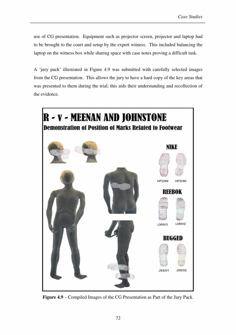
Case Studies
72
use of CG presentation. Equipment such as projector screen, projector and laptop had
to be brought to the court and setup by the expert witness. This included balancing the
laptop on the witness box while sharing space with case notes proving a difficult task.
A ‘jury pack’ illustrated in Figure 4.9 was submitted with carefully selected images
from the CG presentation. This allows the jury to have a hard copy of the key areas that
was presented to them during the trial; this aids their understanding and recollection of
the evidence.
Figure 4.9 – Compiled Images of the CG Presentation as Part of the Jury Pack.

Case Studies
73
At the time of trial one of the accused brothers had died. The footwear marks showed a
relatively clear pattern around the head, shoulders and the legs. These patterns could be
attributed to the shoes from the two brothers. There was a unclear and very partial mark
near the ear which could be aligned with part of the boot pattern of the third suspect but
it was extremely indistinct and could provide no more than limited support for an
assertion that the mark was made by his shoes. The evidence pointed towards the two
brothers, which were believed to be the main perpetrators of the attack. Subsequently
they were found guilty of murder.
4.3.5 Conclusion
There were a number of issues that arose during the construction of this CG
presentation that may aid any future constructions. By tackling these issues, it helps to
prevent any possible dispute regarding its use within court. A particular concern in this
presentation was regarding the orientation in which the image of the mannequin body
was displayed. Since it is not possible to know for certain the orientation of the victim
during the attack, illustrating the victim’s body in anything but a floating neutral stand
up position would introduce bias and open up the evidence to speculation.
4.4 Case Study 3
This case was headed by Jennie Lewis from FA, and deals with blood spatter evidence.
Analysis of blood spatter can reveal the area of the crime scene and aid in determining
the sequence of events that may have transpired.
4.4.1 The Case
The body of a woman was found dead in her car. Subsequent investigation into her
household uncovered the suspect to the husband of the deceased. Detailed examination
of the house revealed areas of bloodstains where attempts had been made to conceal the
bloodstain evidence.
4.4.2 Requirements of the Case
The difficulty faced in conveying the blood spatter evidence in court is due to the
number of items in the scene that were rotated and repositioned by the suspect; in an

Case Studies
74
attempt to conceal the evidence. It is the aim of the presentation to illustrate the
conditions of the scenes before and after examination by the SOCOs and demonstrate
how these changes occurred.
It is difficult to convey this evidence in a way that was easy to understand without the
use of CG displays. This is evident from the expert witness’s attempt to produce an
effective illustration of the crime scene using 2D paper cut-out model. Layers of paper
representing the layers of furniture in the scene could be removed, rotated or flipped to
demonstrate the concealment of the evidence. Although this approach allows the expert
witness a great degree of interaction, it is quite cumbersome due the masses of loose
paper presence.
In order to gain a full understanding of the extent of the concealment, the conditions of
the crime scene before and after examination by investigators needed to be viewed side
by side. A more detailed illustration of key areas of the scene is warranted to allow the
viewer to comprehend not only the before and after situation but how the changes
occurred.
4.4.3 Presentation
Web-based presentation was again used as a method of displaying the presentation. In
order to provide the interactivity that is required to fully illustrate the extent of the
concealment, QTVR object movies and Flash technology was also implemented. This
provides a time base presentation rather than just static images. The ability of web-
based presentation can be extended to accommodate this through installation of plug-in
software.
The CG presentation was divided into three main sections which can be viewed side by
side for comparison as illustrated in Figure 4.10. The first section illustrates the crime
scene on arrival where the bloodstain evidence had been concealed. The second section
shows the scene following post examination and illustrates the scene prior to any
attempts of concealment. Through placement of hot spots within the images of section
one and two, layers in the scene can be removed to uncover the underlying blood

Case Studies
75
evidence as presented in Figure 4.11. Dimensions of the room and its key furniture are
also indicated on the images to give a scene of scale.
Figure 4.10 – Screenshot Showing the Three Sections of the CG Presentation.
Figure 4.11 – Activation of Hotspots to Remove Layers in the Scene Revealing
Underlying Evidence.

Case Studies
76
The third section of the presentation provides a series of details in support of section
one and two. Using QTVR object movie, a demonstration of how the mattress was
flipped over to conceal the bloodstain can be shown. In addition, rotation of the rug can
be shown in a similar fashion. Flash movie technology provides an additional tool in
which the jury can view the events of the crime scene. The Flash movie provides an
overview of the evidence and presents it in a linear movie by illustrating the sequence of
events that may have transpired in the concealment process of the bloodstains.
4.4.4 The Trial
Due to the overwhelming evidence against the suspect, a plead of guilty was made and
the CG presentation was not required.
4.4.5 Conclusion
Although the CG presentation was never used in court, several lessons can be learnt
from its construction. Displaying three sections on a single page can often overwhelm
the viewer with information and produce a sense of confusion. Presenting one section
on a page at a time will help concentrate the viewer towards the piece of evidence that
the expert witness is trying to convey over at the time.
The setup of each computer can vary considerably from the software browser to the
resolution of the screen. Maintaining the look and feel regardless of the client system or
browser used are challenges often faced when designing a webpage. Viewing the CG
presentation on computers with different resolutions may result in sections not being
displayed on screen and require scrolling to bring the section into view. In addition,
different browsers often interpret the data slightly different and therefore can display the
format of the CG presentation in a slightly altered state such as the font, colour or
positioning within the webpage.
Another problem encountered from testing of the presentation within FA was the lack of
plug-in software in a large number of the computers. With absents of the correct plug-
in, QTVR movie or Flash movie may not be displayed.

Case Studies
77
4.5 Case Study 4
This 1:1 taping case is headed by Tiernan Coyle. In collaboration with TVP, this case
aims to replicate the success shown in case study 1 and build on the popularity of the
1:1 taping technique.
4.5.1 The Case
Following a tip off from what turned out to be the son of the suspect, the police attended
a scene to discover the body of a woman lying in the lounge, draped over the couch
with two stab wounds to the throat. Employing the 1:1 taping technique was considered
to be the best approach in preserving and collecting the evidence in the scene. In order
to ensure completeness, both the front and back of the victim was taped. Areas of heavy
bloodstains were avoided such as the head, throat and upper back and right buttock. A
total of one hundred and nine tapings were taken from the body of the deceased;
supported by extensive photographs that recorded the position of each taping on the
body.
Information received by the police led to the arrest of a suspect. Confirming his
presents at the scene, the suspect claims that a fight took place between the victim and
two others but he had no involvement and made no contact with the deceased. The
suspect’s top, shirt and trousers were seized and submitted to the laboratory for fibre
analysis. This would help reveal the true extent of contact between the suspect and
deceased.
4.5.2 Requirements of the Case
The requirement of this case is very much similar to those of case study 1. The aim is
to present the density of fibres found on each taping and relate it to the position it was
found on the body. Since the front and back of the victim was taped, illustration of the
taping is slightly more complex than case study 1. Analysis revealed close contact
between trousers and lower body, particularly between legs, correlation with fresh
bruising noted on post mortem. As discussed in subsection (4.2.2), presenting 1:1
taping evidence in the form of tables is difficult to understand and a CG presentation
would greatly aid in conveying this evidence to the jury.

Case Studies
78
Due to the nature of web-based technology, it is difficult to maintain the exact visual
appearance that is intended, as discussed in subsection (4.4.5). Therefore, a decision
was made to utilise alternative method of presentation in order to avoid these
drawbacks. Standalone Flash technology presents an ideal alternative whereby the
presentation can be accurately displayed despite any change in screen resolution. In
addition, one section of the presentation should be viewed at a time and information
kept to a minimal so as not to confuse and overwhelm the viewer.
4.5.3 Presentation
The presentation was divided into five sections; providing sufficient details and focus to
be presented. The first section presents an overall transfer of fibres from the accused to
the deceased. This helps establish the extent of contact and aid in disproving the
statement that the accused had no contact with the deceased. A model diagram of the
accused and deceased were used, with the clothing represented by colour and patterns
obtained from scene photographs. Since the evidence in this section was related to the
overall transfer and not the exact position on the body, there was no need to utilise
scene photographs; keeping the evidence objective (Figure 4.12).
Figure 4.12 – Overall Transfer of Fibres

Case Studies
79
However, in section two and three, the evidence presented is concerned with the
distribution of fibres on the surface of the deceased body. Therefore, scene photographs
have been implemented to accurately represent the body; showing the position of the
tapings for both the front and back of the deceased. In order to avoid a shock factor, the
face of the deceased on the photographs was blocked out and the photograph faded.
This was to allow the evidence to be related to the position on the surface of the body
without drawing the focus on the image of the deceased itself. In addition, colour can
often add confusion to an image, therefore the colour from the photographs was
removed. Section two of the presentation deals with the overall distribution of fibres on
the body of the deceased as illustrated in Figure 4.13. The frequency of the fibres were
grouped into 5 categories and colour coded with darker colours representing increase
frequency of fibres. The areas of taping on the photograph of the body were then
coloured accordingly.
Figure 4.13 – Overall Distribution of Fibres.
Section three provides a detailed account of each fibre distribution on the surface of the
deceased. In addition to an overview photograph of the deceased, a selection of scene
photographs were chosen to represent a more close up view of each section of the body.

Case Studies
80
With a blue spot representing a single fibre, each fibre found on the body of the
deceased that was a match to the suspect’s clothing were represented on the scene
photographs as shown in Figure 4.14.
Figure 4.14 – Detailed Distribution of Fibres.
Section four shows scanned images of the tapings taken from the body. An image of
the deceased is shown with areas of tapings numbered to show its position. As shown
in Figure 4.15, clicking on the numbers in the centre console displays its corresponding
image of the tapings for viewing.
Figure 4.16 shows section five which displays a range of scene photographs that may be
useful to the expert witness during the trial. Each photograph has been converted to grey
scale to allow the details of the scene to be seen more accurate without the confusion
that colour can bring. The photographs taken by the SOCOs were numbered during the
investigation and these were carried over to the presentation. By clicking on the
number, the corresponding scene photograph was displayed.

Case Studies
81
The presentation was structured so that five sections were control from a central
console. A reset button placed in each section reverted the user back to this central page
and allowed the presentation to proceed in any order.
Figure 4.15 – Scanned Images of Tapings Taken from the Deceased.
Figure 4.16 – Display of Scene Photographs.
Case Studies
82
4.5.4 The Trial
Reading Crown Court where the trial was held possessed limited equipment to deal with
the demands of a CG presentation. Although plasma screens were available which
could be linked to laptops, the resolution was poor.
The jury pack submitted was similar to that used in Case Study 1, which consisted of a
collection of photographs supported by the CG presentation. With the substantial
evidence against the accused, a verdict of guilty was given and sentence of life
imprisonment was passed.
4.5.5 Conclusion
Publishing the presentation in an executable format produced a self contained
presentation that requires no plug in and therefore run on all PC systems. Additionally,
the scalable nature of the presentation means that the visual presentation is not affected
by the resolution that the presenting computer has been set to. Therefore, using the
presentational technology enables the presentation to be view as intended independent
of which computer is used.
4.6 Historical Development
Construction of the four case studies have help demonstrate the effectiveness that CG
presentation can have in the courtroom and the potential benefits that it can bring to
forensic science. Implementation of the four CG presentation within FA has not only
demonstrated its benefits and ease of use to the forensic scientist involved in the cases,
but by word of mouth and demonstrations has allowed other scientist to become aware
of these alternative techniques available. With each case study carried out, lessons have
been learnt which have aided in the development of later case studies. These have
helped establish a good foundation and guidelines in which to produce effective
forensic CG presentations. These include:
• Engagement of the Viewer – The presentation should engage and retain the
attention of the viewer otherwise vital evidence may be overlooked. The
opportunity must not be lost in communicating the case.

Case Studies
83
• Minimal Information – Care must be taken not to overwhelm the viewer with
information on the screen. Only the evidence that is being communicated by the
expert witness at the time should be displayed on screen. This will focus the
viewer on the relevant evidence rather than allowing them to gaze at unrelated
information.
• Structure – Time should be taken to develop a well structured CG presentation.
This will allows information to be recalled easily in any order by the expert
witness.
• Minimise Shock Factor – Cases where the crime has resulted in death often
involves showing photographs of the deceased that may not be received kindly
by the jury or the family of the victim. Therefore, unless particular references to
the photographs are required, images used in a presentation should be replaced
with representation. In cases where scene photographs are required, images
should be desensitised to avoid unnecessary shock factor.
• Compatibility – The way a computer is setup such as the screen resolution and
software installed can directly affect the way that the CG presentation is
displayed. Every possible care should be taken to maintain the appearance of
the presentation regardless of the computer used.
• Clarity – Crime scenes that have many colourful items within the scene can
overwhelm a photograph and distract the viewer from the relevant information.
By converting a photograph to grey scale, this can help eliminate this problem
and assist in focusing the viewer’s attention.
4.7 Summary
This chapter has followed the construction of four CG presentations from four case
studies. In collaboration with FA it has provided an insight to the challenges faced in
constructing a CG presentation for use in the courtroom. Lessons learnt during their
construction has aided in establishing guidelines. These can be applied to any future
constructions and aid in producing an effect CG presentation as well as preventing
possible challenges by opposing council.
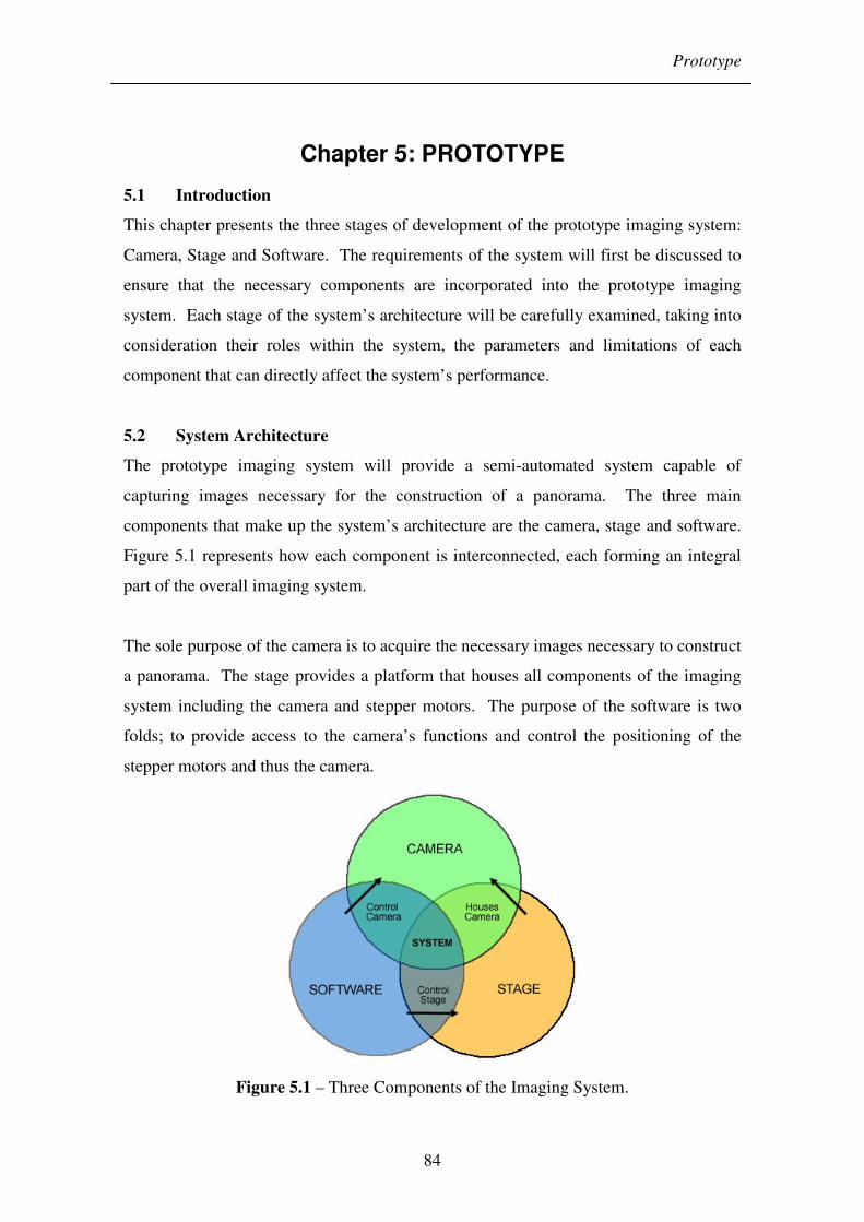
Prototype
84
Chapter 5: PROTOTYPE
5.1 Introduction
This chapter presents the three stages of development of the prototype imaging system:
Camera, Stage and Software. The requirements of the system will first be discussed to
ensure that the necessary components are incorporated into the prototype imaging
system. Each stage of the system’s architecture will be carefully examined, taking into
consideration their roles within the system, the parameters and limitations of each
component that can directly affect the system’s performance.
5.2 System Architecture
The prototype imaging system will provide a semi-automated system capable of
capturing images necessary for the construction of a panorama. The three main
components that make up the system’s architecture are the camera, stage and software.
Figure 5.1 represents how each component is interconnected, each forming an integral
part of the overall imaging system.
The sole purpose of the camera is to acquire the necessary images necessary to construct
a panorama. The stage provides a platform that houses all components of the imaging
system including the camera and stepper motors. The purpose of the software is two
folds; to provide access to the camera’s functions and control the positioning of the
stepper motors and thus the camera.
Figure 5.1 – Three Components of the Imaging System.

Prototype
85
5.3 Requirements of the System
Adhering to guidelines during the design and construction of the prototype imaging
system will ensure that the fundamental features are incorporated, and aid in providing a
practical and realistic tool for forensic use. In subsection (2.4.1), basic requirements of
the imaging system were formulated following meetings with staff from FA. This
section aims to expand on these requirements, providing a framework for the
subsequent design and construction of the imaging system. These are listed below and
illustrated in Figure 5.2:
• Camera
o Low Cost – With the high number of digital cameras available on the
market, a careful balance between cost and quality must be attained;
ensuring that the overall cost of the imaging system remains low.
o Quality – The resolution of the camera will govern the quality of the
output images and thus the panorama. For the purpose of forensic use,
the camera should be sufficient quality to accurately depict the scene and
its contents.
o Accessibility – The ability to control the camera via a computer is vital in
providing a semi-automated system. This allows the computer to initiate
the capture process without physical human interaction with the camera.
The use of removal memory places limitation on the number of images
that can be stored. The ability to transfer images directly to the hard
drive of a computer removes this limitation, and with the substantial size
of today’s hard drives, file size becomes insignificant.
o RAW Format – The camera should possess the ability to capture in
RAW format. This is an important feature that aids in preserving the
integrity of any images captured by preservation of details within an
image. RAW format is essentially an image direct from the image sensor
and therefore has not undergone any post capture processing that may
result in lost of data.
o Manual Control – The lighting conditions of each crime scene varies
considerably. The camera should posses the ability to provide manual

Prototype
86
control over the shooting setting thus allowing for consistent exposure to
be attained. This ensures a smooth transition between images and aid in
the stitching process.
• Stage
o Durability – The construction of the stage should be of sufficient
robustness to support all components of the system and endure the
routine transportation of the equipment to and from scenes.
o Portability – Ensuring that the system is light weight will provide easier
transit to and from scenes and aid in persuading users to employ at a
crime scene.
o Minimise Contamination – Issues of contamination is a major concern
especially when dealing with crime scenes which can have drastic effect
on the outcome of an investigation. Therefore minimising the risk of
contamination is priority in the construction of the imaging system.
Suspension of all loose components on the stage will ensure minimal
contact with the scene.
• Software
o Ease of Use – The software must be simple to operate and self
explanatory to ensure that users of any technological ability can utilize
with little difficulty.
o Time – Time available to capture a crime scene in its untouched state is
relatively short. The system should complete its cycle of capture in a
relatively short period of time without compromising on the quality of
any images acquired.
o Format Conversion – The software should be able to convert any RAW
images captured by the camera to a more useable format which can then
be applied to the stitching software.
o Modes – Different modes should be available in the software to allow
user of different experience a varying degree of control.
o Progress Report – While the imaging system is in the process of capture,
indication to the number of images captured and its transfer should be
displayed to allow its progress to be charted.

Prototype
87
o Tutorial – A tutorial should be accessible to provide any additional
information that a user may require concerning the theory and operation
of the imaging system.
Figure 5.2 – Requirements of the Imaging System.
5.4 Hardware
The hardware of the imaging system comprises of the camera and stage. These will be
examined in turn, giving careful consideration to the parameters of each components
utilised. Identification of the limitations will not only allow the capabilities of the
imaging system to be realised but also enable solutions to be proposed to overcome
them.
5.4.1 Camera
The primarily role of the camera within the imaging system is to capture the required
images necessary to create a panorama of the scene. A decision to utilise still digital
cameras rather than surveillance CCD cameras or video cameras is due to their lower
costs and generally greater resolution that digital cameras exhibit as discussed in
subsections (3.4.3.3).

Prototype
88
Careful consideration was given regarding the type of digital camera to implement into
the imaging system. The requirements stated in section (5.3) for a digital camera enable
a number of cameras to be excluded from consideration. Following a comprehensive
search of the market at the time, the Canon PowerShot G3 was revealed to be the ideal
candidate for use in the proposed imaging system (See Appendix C).
The Canon PowerShot G3 digital camera offers high quality at a low price. Its ability to
be controlled directly by a computer through a USB interface makes this ideal for semi-
automating the capture process. Through the supplied open-source Visual Basic (VB)
software, the functions of the camera can be integrated into the system’s software.
Images recorded by the camera can also be directly transferred to the computer’s hard
drive, removing the necessity for a high capacity memory card and minimising human
interaction.
Determining the limitation of the camera is vital to ensure that the constructed system is
adequate to serve its purpose. While the majority of the camera’s specifications can be
attained from the manufacturer, several features of the camera require further
calculations or experimental work to determine.
5.4.1.1 Field of View
The FOV of a camera’s lens as illustrated in Figure 5.4 indicate how many degree of a
scene is captured within a single image.
Figure 5.3 – FOV of Camera’s Lens.
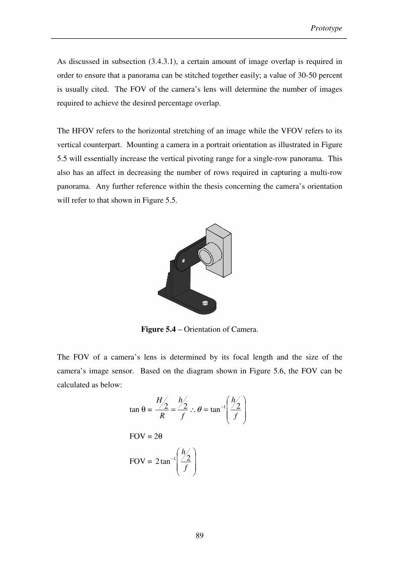
Prototype
89
As discussed in subsection (3.4.3.1), a certain amount of image overlap is required in
order to ensure that a panorama can be stitched together easily; a value of 30-50 percent
is usually cited. The FOV of the camera’s lens will determine the number of images
required to achieve the desired percentage overlap.
The HFOV refers to the horizontal stretching of an image while the VFOV refers to its
vertical counterpart. Mounting a camera in a portrait orientation as illustrated in Figure
5.5 will essentially increase the vertical pivoting range for a single-row panorama. This
also has an affect in decreasing the number of rows required in capturing a multi-row
panorama. Any further reference within the thesis concerning the camera’s orientation
will refer to that shown in Figure 5.5.
Figure 5.4 – Orientation of Camera.
The FOV of a camera’s lens is determined by its focal length and the size of the
camera’s image sensor. Based on the diagram shown in Figure 5.6, the FOV can be
calculated as below:
tan θ =
=∴=
−
f
h
f
h
R
H2tan22 1
θ
FOV = 2θ
FOV =
−
f
h2tan2 1

Prototype
90
Figure 5.5 – Relationship of FOV and Camera’s Dimensions.
The CCD format indicates the dimension of the CCD sensors. The specification list in
subsection (5.4.1) shows this to be 1/1.8 for the Canon PowerShot G3. From Table 3.1
in subsection (3.3.1.3), the dimensions of the CCD sensor is:
Horizontal dimension of CCD – 5.319 mm
Vertical dimension of CCD – 7.176 mm
Table 5.1 shows the calculated value of the VFOV and HFOV for the Canon PowerShot
G3 digital camera.
FIELD OF VIEW
Lens Focal Length (mm) Vertical FOV (Deg) Horizontal FOV (Deg)
7.2 53.0 40.6
Table 5.1 – FOV of the Canon PowerShot G3.
5.4.1.2 Resolution
It is important for the purpose of forensic work, that the digital camera utilised in the
imaging system possesses adequate resolution to accurately represent the scene and its
contents. Resolution ultimately comes down to how much detail you can see in an

Prototype
91
image [Imaging Resource, Accessed 2006]. The camera’s ability to resolve detail is
determined by a number of factors, including but not limited to the performance of the
camera’s lens, the number of addressable photo elements and the electrical circuits in
the camera [BSI, 2000]. This subsection aims to determine the performance of the
camera’s lens and thus the capability of the proposed imaging system.
5.4.1.2.1 Focus
A lens such as the Canon PowerShot G3 that is capable of high resolution performance
can be greatly affected by the camera settings. The focus setting of the camera is one
such issue that can reduce the effective resolution. The ability to autofocus is essential
in order to provide semi-automation to the imaging system. Autofocus is a feature of
most digital cameras where it automatically moves the lens in and out until the sharpest
possible image of the subject is obtained. In contrast, manual focus which is available
on some high-end digital cameras requires that the user manually adjust the focus of the
lens to obtain a clear image. Manual focus is impractical for the purpose of the imaging
system since the present of the user is required for the capture of each image. Although
autofocus is vital to the imaging system, there are drawbacks associated that can greatly
affect the stitching process. There are several methods of autofocus; but generally the
digital camera will designate the middle section of an image as illustrated in Figure 5.7
as the centre of focus.

ERROR: stackunderflow
OFFENDING COMMAND: ~
STACK:
Application Case-Study
119
Chapter 6: APPLICATION CASE-STUDY
6.1 Introduction
The procedures involved in assessing the value of the imaging system does not lie in the
number of features or types of equipment it possesses, but in its ability to perform in
real world situations. The ability to quickly construct an accurate VE corresponding to
a real scene can be an extremely powerful tool [Gibson, 2000]. This chapter presents an
evaluation and assessment of the imaging system in relation to its value as a forensic
tool. The imaging system will first be applied to a crime scene scenario where the
performance of the system and its resultant virtual scenes can be examined. The
imaging system will then be presented to a representative group of intended users for
evaluation. This will provide invaluable data regarding the practicality of the imaging
system. Refinement and improvements can then be applied to the imaging with the
feedback received.
6.2 Trial of Imaging System
The development of the imaging system resulted in four separate components: the
camera, tripod, circuit box and platform. Assembly of these components as well as a
laptop are required before the imaging system is ready for deployment. This will yield
a semi-automated imaging system capable of acquiring images that are necessary for the
construction and rendering of a cylindrical or spherical panorama. Its capacity as a
forensic tool lies in its ability to provide a simple to operate system and reproduce an
accurate representation of a crime scene. Deployment of the imaging system in a real
world crime scene will aid in gauging its level of functionality.
Lancashire Police and Thames Valley Police force showed keen interest for me to
attend low profile cases and trial the prototype imaging system with police personnel.
However, due to the sensitivity of evidential material, law advisors to the police held
reservation on the impact that the presence of the imaging system and non-police
personnel may have on the case at hand. This resulted in both police constabularies
abandoning the trials. The construction of a simulated crime scene that replicated the
real world as closely as possible provided an alternative method for the trial of the

Application Case-Study
120
imaging system. Although a simulated crime scene cannot match the level of details
present in a real world crime scene, it will nevertheless demonstrate the potential and
ability of the prototype imaging system.
The aim of the trial is two-folds; to establish the functionality of the imaging system and
also demonstrate the potential of a constructed virtual scene. The simulated crime scene
utilises a secluded lodge as the location of crime. This allows control over the
movement of items within the scene and removes the drawbacks of moving vehicles.
As discussed in subsection (3.4.3.1), the movement of objects from one image to
another (i.e. moving vehicles) may result in blurring of the resultant panorama. The
main crime scene is situated within the lodge where a simulated crime is portrayed in
which a victim lies suffocated. Items of evidence placed around the representation of
the victim’s body aims to illustrate that a perpetrator had gained entry to the lodge and a
struggle took place with the victim.
Assessing the function of the overall imaging system involves capturing a series of
images necessary for both a cylindrical and spherical panoramas. This allows for a
direct comparison between the two types of panoramas in terms of the process involved
in capturing the images and their output panoramas. Since a crime scene is not limited
to the immediate area in which the victim’s body is located, capturing panoramas
outside the lodge will provide a sense of surrounding. Evaluating the system in an
outdoor location will allow for its ability to function in surroundings that cannot be
controlled to be assessed alongside an enclosed and controlled site.
Demonstrating the potential of a constructed virtual scene involves illustrating the
flexibility and ability to accurately represent a crime scene. The flexibility of a virtual
scene lies in its ability to interlink a number of panoramas through hotspots and thus
give the user a sense of movement. In addition, hotspots allow all case related material
to be integrated into the virtual scene. This can include images of the items of evidence
allowing for a more detailed scrutiny and case notes, thus providing a logical folder for
easy viewing.

Application Case-Study
121
Due to the lack of available forensic and police personnel for the trial at the time, the
assessment of the imaging system is based on my own personal views. Although this
may differ from the professional communities, it does help to highlight any potential
problems that may be encountered.
The first challenge that the imaging system may be faced with is transportation of the
equipment to the crime scene. As a method to prevent contamination of a crime scene,
forensic stepping plates are often used which outline a common pathway that all
personnel follow. This restriction in movement within a crime scene and the number of
separate components and its weight may present a challenging task in the transportation
and assembly of the imaging system. Limiting the pathway inside the lodge enables the
trial to emulate some of the conditions that may be experienced in a real world situation.
Due to the number of components involved, two trips were required to transport all
equipment to the site. Once this was achieved, assembly of the imaging system was
found to be relatively quick and straightforward. It was found that the tripod and
platform should be transported first to ensure that the frame is established at the earliest
stage possible enabling the subsequent components to be supported.
Images necessary for the construction of both a cylindrical and spherical panorama were
acquired of the simulated indoor and outdoor crime scene. The time taken for the
acquisition of images was found to differ depending on the type of panorama and
graphic format utilised. In cylindrical mode, the average time taken was five minutes
and forty five seconds whereas a spherical panorama took a considerably greater time of
twenty nine minutes and thirty seconds. The increase in time for spherical panorama is
not only evident in the capture process but also in the construction and display of the
panoramas. This is due to the large number of images involved resulting in a large
QTVR panoramic file that requires an increase in processing power and memory to
render and display the panorama efficiently. The use of RAW format further increases
the time of capture due to the large size of the file compared to JPG that must be
transferred to the hard drive of the computer.

Application Case-Study
122
Following construction of the panoramas and additions of the hotspots to form the
virtual scene, it was discovered that QT 6.3 is required to correctly allow activation of
the hotspots. Due to an unexplained bug within QT, versions of QT greater than 6.3
resulted in failure of the hotspot. (QT 6.3 is supplied on the supplementary CD).
In terms of the constructed panoramas, greater flexibility can be seen in the spherical
panoramas. The drawbacks of cylindrical panoramas lies in its limited VFOV as
illustrated in Figure 6.1 whereas spherical panoramas offer the user the ability to view a
full scene. Therefore, positioning of the imaging system becomes of greater importance
for the capture of a cylindrical panorama. Important evidence may not be documented
and therefore overlooked as a result of positioning the imaging system in close
proximity to a subject. This is evident in the cylindrical panorama captured from the
trial which illustrates the failure to capture evidence two and six. In order to overcome
this limitation, a cylindrical panorama should be captured from a number of locations
within the scene to ensure that any evidence not captured in one panorama is present in
another
Figure 6.1 – Limited VFOV of a Cylindrical Panorama.
Although a spherical panorama offers the advantage of increase VFOV over its
cylindrical counterpart, due to its increase number of overlapping images, spherical
panoramas are more prone to movement within a scene. This is evident in the spherical
panorama of the outside of the lodge as illustrated in Figure 6.2, where movement of the
branches resulted in slight blurring of the resultant panorama.

Application Case-Study
123
Figure 6.2 – Blurring of the Resultant Panorama.
6.3 Evaluation Approach
The imaging system as a forensic tool can brings many benefits to the procedures
involved in documentation of a crime scene. However, real world application of the
imaging system is dependent on the willingness of forensic personnel to utilise at a
crime scene. There are many aspects of the system that may encourage and also
discourage the use of the imaging system. This subsection aims to attain the views from
the intended end users and identify any potential obstacles that may be faced with the
application of the imaging system. In order to obtain the necessary information, a
representative group of forensic and law enforcement personnel would be used to
analyse and evaluate the imaging system. Each personnel in turn are introduced to the
imaging system for the first time and should possess no prior knowledge in its
operation. This ensures that the level of knowledge is equal and thus the evaluation will
provide a good representation of how the system will be received.
As an initial form of data gathering, a questionnaire as illustrated in Figure B.1 is
presented to each user; to be completed throughout the evaluation process. The
questions aim to gauge the value of a number of features of the system by means of a

Application Case-Study
124
likert scale. The evaluation of the imaging system commences with a quick verbal
introduction and presentation of the tutorial to the user. This enables users to
familiarise themselves with the key concepts and operation of the imaging system
before trialling the system. Once this was accomplished, the components of the
imaging system in its unassembled state were presented to the users. Invited to handle
the equipment to obtain a sense of weight and ease of transportation, the user is then
requested to assemble the system to its fully functioning state and initiate capture of a
panorama in RAW format. This demonstrates the clarity of the tutorial and its ability to
translate instructions to the user in the actual operation of the imaging system. This
hands-on approach allows users to gain first hand experience of the system which aids
in revealing any difficulties that may be encountered. With the acquired images in
RAW format, conversion to a more usable graphic format is necessary for application to
the stitching software. Guided by the tutorial, the user is instructed to batch convert the
captured images to the JPG format. Once the images are converted, the operation of the
imaging system is complete. Construction of a panorama from the acquired images are
performed through third party stitching software and therefore not an element of the
imaging system. The user are therefore not required to apply the images to a stitching
software, but instead is presented with the simulated crime scene constructed in section
(6.2). This will illustrate to the users the possibly virtual scenes that can be constructed
as a result of utilisation of the imaging system.
Following sufficient time for the users to explore the constructed virtual scenes, each
user was subjected to a structured interview. Illustrated in Figure B.2, the structured
interview aims to acquire constructive criticism regarding the capability and practicality
of the imaging system. Opinions on how the imaging system will perform in real world
situations and its possible reception within their departments will also be the focus of
the interview. Focus will also be placed on the current status of digital imaging within
their individual department and opinions on the current crime scene documentation
techniques will be acquired. This allows the true value of the imaging system to be
realised, when assessing its performance alongside current crime scene documentation
techniques.

Application Case-Study
125
6.4 Analysis of Results
The intention to expose a mixed group of at least twenty forensic and law enforcement
personnel to the imaging system was faced with setbacks. This was due to an
unpredictable emergence of a high profile case which resulted in the majority of the
volunteers that were expected to attend the trial to cancel just a few hours prior. As a
result, only seven volunteers were available for evaluation of the imaging system and
therefore any statistical analysis would not provide any reliable information.
Nevertheless, information gathered through the questionnaires and structured interviews
provide valuable data that helps to indicate and reflect on possible issues that the
utilisation of the imaging system may create. Different areas of expertise and
experience of the volunteers can illustrate the diversity of the imaging system and how
it may benefit their work. Table 6.1 present the seven volunteers that took part in the
evaluation including their area of expertise.
Volunteer Role Area of Expertise
1 SOCO Crime Scene Processing
2 SOCO Crime Scene Processing
3 Forensic Photography
4 Forensic Footwear Marks
5 Forensic Chemistry
6 Forensic Biology
7 Forensic Toxicology
Table 6.1 – Volunteers of the Evaluation.
The responses from the questionnaire and structured interview allow us to gauge the
achievement of the requirements that were outlined in chapter 2. Comparisons of these
responses will allow correlation of a number of features of the imaging system to be
established and these provide a possible explanation behind the responses.
The function and operation of the imaging system can be divided into two areas:
assembly of the hardware and operation of the software. Ease of use of the imaging
system is a key requirement that will allow users of any ability to operate with little

Application Case-Study
126
difficulty. Responses from the questionnaire and structured interview will allow us to
gauge whether these have been achieved and also pose possible explanations for the
results.
The assembly of the hardware encompasses all stages, from the transportation of the
equipment to the assembly of the imaging system. Question four of the questionnaire
aims to evaluate the level of ease at which the volunteers found the assembly of the
imaging system. There were no serious difficulties observed by the volunteers during
the evaluation however, some of the volunteers found the task to be easier than others.
The difference in responses underlines the presence of weaknesses within the prototype
imaging system that can be due to a number of factors. Possible explanation can be
established by comparison of a number of system’s features to the responses received
concerning the ease of assembly.
The imaging system comprises of four components that require transportation and
assembly before deployment is possible. The manageability of the system in terms of
number of components can have a direct bearing on the ease of assembly. The
assumption is that the volunteers that found the number of components to be
manageable will have also experienced an easier assembly of the system. The responses
indicate the volunteers found the number of components to be generally manageable
and acceptable which supports the assumption. Volunteers that found the ease of
assembly to be average also found the manageability of the components to be average.
In contrast, those that experienced an easier setup of the hardware also found the
manageability of the component to be greater. It is therefore plausible that reduction in
the number of components associated with the imaging system will result in a greater
ease of assembly.
The weight of the imaging system is an important factor which may affect not only the
ease of assembly, but the sturdiness and desire of the end users to utilise the system.
The assumption that a more light weight system would result in an easier assembly of
the imaging system is reflected in the responses received. Five of the seven volunteers
found the weight of the imaging system to be quite manageable while the remaining two

Application Case-Study
127
found it to be average. This shows a positive correlation, as the manageability of the
weight of the system increases, the ease of assembly becomes easier.
Through the structured interview, it was established that judgement on the weight of the
system was based on reference to current forensic and law enforcement equipment.
Volunteer 6 expresses that “it is no bigger or heavier than other equipment that we lug
around”. Although, these views are shared by all volunteers, there is still a desire for
equipment to be lighter in weight. Volunteer 2 states that “it is the nature of our job that
we carry a lot of equipment, however, being a woman it is often difficult to manage the
weight associated with these”.
Construction of an ultra light system may be beneficial for the purpose of transportation
and the assembly of the imaging system, but it can also be detrimental to other aspects
of the system. Use of light weight material often denotes increase in cost and a decrease
in the sturdiness of the system. Since sturdiness is an equally important requirement of
the system, obtaining a balance between weight and sturdiness is essential. Volunteer 1
says “in practical application of the system, it is going to be knocked over and thrown
into vans. The system needs to be robust”. While relating the responses of weight and
sturdiness, it is found that volunteers that found the system to be lighter also found it to
be more fragile. The majority of the comments received on the sturdiness of the system
were with regards to the tripod. The tripod that was utilised in the imaging system was
considered to be too fragile and on application of pressure resulted in bending of the
tripod legs. In addition, volunteer 3 states that the imaging system is very top heavy
which can be prone to windy conditions.
The ability to carry out instructions is only as good as the instructions themselves.
Failure to communicate instruction to the users can result in difficulties during the setup
of the hardware. Question eight aims to identify any concerns regarding the tutorial and
its ability to provide adequate information for the setup and operation of the imaging
system. The responses from the questionnaire indicate that the tutorial provided quite
adequate and average assistance to the users. The correlation observed from the
responses illustrates that those who found the tutorial to be quite adequate also

Application Case-Study
128
experienced fewer problems during the assembly of the system while those who found
the tutorial less helpful also experienced more difficulties in assembling the system.
Volunteer 2 reveals that “Initially from the tutorial, the setup of the system appears
complicated but once you have done it, it is actually quite straightforward and I would
find it easy to do second time around”. Improvements to the tutorial may result in users
finding the initial assembly of the imaging system to be less problematic. Data gathered
from the structured interview indicated that the main weakness associated with the
tutorial was its layout. Volunteer 7 pointed out that the number of options available on
the main menu in the tutorial can cause confusion. By dividing the tutorial into three
main section: hardware, software and information, it provides a more logical layout and
therefore allows the correct information to be located more efficiently. Volunteer 1
noted that the hardware setup in the tutorial consisted of a series of consecutive slides.
If a particular area required further attention and needed to be revisited, the user is
forced to view the hardware presentation from the beginning and must proceed through
the slides before reaching the desired information. Division of the hardware tutorial
into several sections will allow users to view the desired pieces of information without
the need to view the entire presentation.
In addition to the number of components, weight of the system and the tutorial that has
been shown to affect the ease of assembly, the volunteers have expressed area of the
system that require further attention. One particular area involved the connections of
the two stepper motors to the circuit box. The cables and connectors from the stepper
motors are identical in every aspect and this has led to confusion for some of the users
that found difficulties in determining the correct connector and its corresponding socket
on the circuit box. Incorrect connection of the stepper motors to the circuit box will
result in the system’s software activating the wrong motor, and may ultimately cause
damage to the system due to the restriction in rotation of the vertical axis. Although the
sockets on the circuit box are labelled to indicate the connections of each of the motors,
determining which stepper motor is one and two was found to require constant reference
to the tutorial. Volunteer 7 and volunteer 1 suggest colour coding as a method to
quickly allow identification of the correct connector with its corresponding socket.

Application Case-Study
129
Volunteer 1 says “basically the male and female parts should be colour coordinated so
you won’t put the wrong motor into the wrong socket”.
In addition, concerns regarding the length of the cables were expressed. Volunteer 3
says “the length of the cables seem to be extremely long. Cables should be just the right
size and length”. This will aid in maintaining an organised system and reduce the
movement of cables during the capture process which can cause blurring of the resultant
panoramas.
The task of attaching the camera to the panoramic head caused complication and
confusion to a number of users. Attachment of the camera as discussed in subsection
(5.4.2.2) involves a series of steps that user found cumbersome and difficult to
complete. Volunteer 1 said that “I would like to see some sort of clip that you can just
clip it on and release rather than have to screw it up. That would be more speedy and
easier”. In addition he went on to say that “there is a worry that you may over tighten
the screw causing damage to the camera, yet on the other hand, if it is not tighten
enough, the camera will flop while the motor is rotating”. Determination of the correct
orientation and direction of the camera during its attachment to the panoramic head
caused some confusion which resulted in constant reference to the tutorial. Volunteer 1
suggests “there should be an indication on the panoramic head showing the orientation
of the camera. That way the user only needs to line up the camera to obtain the correct
orientation”.
Once the setup of the hardware is completed, the imaging system is in a state that is
ready for deployment in a crime scene. This stage of the imaging system requires the
user to operate the system’s software in order to initiate the capture process. The
volunteers examined the software and analysed the range of options available to gain a
better comprehension of the abilities of the software. Question six of the questionnaire
aims to identify the level of difficulty associated with the operation of the system’s
software. The responses received from the volunteers’ indicated that the operation of
the imaging system is considered quite easy. However, differences in responses suggest
space for improvement to the system’s software. There are many factors that may be

Application Case-Study
130
advantageous and also detrimental to the experience of the user during the operation of
the system’s software.
The impact that the layout and sequence of button on the user interface has on the
overall operation of the system’s software can be demonstrated by comparison of the
responses from question six and seven of the questionnaire. The response indicates that
users who found the layout and sequence of buttons on the user interface to be quite
intuitive also had an easier experience of the overall system’s software. All users
believe the software interface to be relatively straightforward and was just a matter of
familiarising themselves with it. However, the aim of the software interface is to be
intuitive despite a user’s level of experience with the system. Since four volunteers
found the layout of the user interface to be only average, this suggest that there are areas
of the layout that exist which can benefit from refinement.
One of the principal requirements of any software interface is simplicity. In order to
provide a sense of direction to the users and prevent confusion and incorrect activation
of buttons, the construction of the user interface made use of buttons that remained in an
inactivate state until the correct steps within a stage were reached. Attempts to increase
the intuitiveness of the software and reduce confusion to the user were met with some
criticism. Even though the use of inactivate buttons provided direction to the software,
it was found that the buttons were still visible despite being greyed out in its inactive
state adding to the overwhelming information and buttons on the screen. Volunteer 1
suggests that “rather than just using inactive button which are greyed out, the buttons
should be invisible and only appear when needed. That way, the user is not
overwhelmed with a large number of buttons”. Another method to simplify the user
interface was suggested by Volunteer 2 who says “increasing the size of the buttons
may allow easier identification of the correct buttons”.
As discussed, the tutorial provides information that aims to guide the user through the
process of operating the imaging system. Comparison between the operation of the
system’s software and the tutorial will aid to gauge the effective communicative ability
of the tutorial to the user. The responses indicated that as the ability of the tutorial to

Application Case-Study
131
provide information increases, the operation of the system’s software becomes an easier
task. Therefore improvements to the tutorial which have already been discussed will aid
in increasing the ease in the operation of the system.
Although the use of computers have infiltrated the daily lives of many people both at
home and at work, there still remains groups that possess poor computer skills. This
diversity in computer skills is evident from the responses acquired from question ten.
Although, four of the volunteer rate their computer skills as quite good, the remaining
three volunteers were not as confident in their ability with two considering their skills to
be only average and one considered it to be quite bad. There was no direct relationship
evident between the operation of the system’s software and the computer skills of the
user. This suggests that the software is intuitive and requires no vast amount of
computer skills to operate, therefore achieving a key requirement of the imaging system.
This is evident from the responses, showing the least computer literate user still finding
the system’s software to be relatively easy to operate.
Documentation of a crime scene is a time sensitive issue. Therefore, in addition to
providing an imaging system that is easy to assemble, the time required to prepare the
system for deployment must be relatively short. Question five of the questionnaire
evaluates the volunteer’s opinions on the length of time taken to assemble the imaging
system. The responses received indicated that five of the volunteers considered the time
to be quite short and one user regarded it to be very quick. Only one of the seven
volunteers considered the time for assembly to be average. Many factors may influence
the time that is required to assemble the imaging system. A direct correlation can be
seen where the volunteers that found the assembly of the system to be easier also
considered the time of assembly to be quicker. Due to the correlations established
between the number of components, weight and tutorial of the system with the ease of
assembly, it is possible to assume that these will also have an affect on the time taken
for assembly. Therefore, an increase in the efficiency of assembly of the imaging
system will reduce the time requirements for the setup of the system and thus yield a
more viable imaging system for utilisation in a crime scene.
Application Case-Study
132
With the imaging system assembled and ready for deployment within a crime scene, the
user can initiate the capture process. The time required for the imaging system to
complete its cycle of capture depends on the type of panorama required and the graphic
format utilised. When confronted with the times that are required for the capture
process as stated in section (6.2), the volunteers were asked for their views on this
length of time in comparison to current documentation techniques. Volunteer 1
expresses that “even though a spherical capture takes roughly thirty minutes, the value
of the results justifies the extra time”. The application of the imaging system is viewed
by the majority of the volunteer to be valuable, particularly at major scenes. Volunteer
2 says “The time is no issue at all because in a major scene which is where you would
use this, you allow yourself however long it takes. Thirty minutes is nothing in the
grand scheme of things”. This view is shared by Volunteer 7 that says “even though
you have to evacuate the crime scene for at least half an hour which stops other people
from processing the room, if it’s a big enough case, half an hour isn’t going to make
much difference”.
The success of the imaging system is dependent on its ability to perform and the
additional benefits it can bring to their profession. Relating evidence to the position it
was found in a scene can often be a difficult task with current documentation
techniques. Volunteer 6 says “talking to colleagues, just trying to get an overall picture
is difficult. It is difficult to convey the separation of items in photographs and
diagram”. The ability of the imaging system to tackle this drawback of current
documentation techniques is emphasized by volunteer 1 that states “the imaging system
as an overview of how items relate to each other in a scene is an excellent tool
compared to photography and video since they only give you whatever is in the frame at
one time”.
The ability to enhance the value of a virtual scene by insertion of addition information
through hotspot provides a user with more than just a visual representation of the crime
scene. Over the course of an investigation, case related material can often build up. A
virtual scene provides a method to integrate this information into a logical folder
whereby users can access this through hotspot within the panorama. Volunteer 2 says

Application Case-Study
133
“this can be a very useful method of keeping track of case information and will save
time in preparation for court”.
The imaging system can be a powerful tool that extends far beyond the initial
investigation. Its ability to communicate the crime scene is beneficial not only to the
forensic and police personnel during the course of an investigation but can also serve a
vital role in court as stated by the volunteers. Volunteer 2 explains that “in a major
scene, you sometimes take a coach load of jurors to the scene so that they can take a
look. Potentially, the virtual scene provides a tool where this is no longer needed. It
will certainly help the lay person since photographs and videos alone do not give a true
picture of space”. Volunteer 1 says “people tend to have different version of what they
perceive the scene to be like from the same description. Presenting a scene through
panoramas allows people to obtain similar views of the scene”. Although volunteer 7
recognises the benefits that such a tool can bring in court, he points out area of concern
that arises from its use. He says “the system provides the jury with accessibility to the
information afterwards, they can physically walkthrough and they can follow through
everything that’s going on. The problem that you might encounter is that if you created
a panorama with hotspots and specific piece of evidence has been removed or tainted or
deemed inadmissible, then your presentation is ruined”. Volunteer 3 comments on the
practicality of using such a presentation in court. He says “that the use of this sort of
presentation is limited by the low-tech equipment that UK courts currently have”.
Differences in complexity in crime scenes present challenges for SOCOs to document
all relevant evidence. The imaging system may provide a beneficial tool that aids in
this task. However, due to certain properties of the imaging system, there are some
crime scenes that its application is not appropriate. Volunteer 1 says “wet scenes may
present a problem such as following a fire where there is a lot of water or a body
floating in the sea. The system may not hold up to being wet”. Volunteer 7 says “it
would be a hazard to use the system in scenes that contain flammable solvents because
of the electrics”. The seriousness of the offence would determine the application of the
imaging system. Volunteer 2 says “I can’t really see you would use it for petty crime”
Application Case-Study
134
while volunteer 1 states that “offences such as burglary wouldn’t validate getting that
out and doing a panorama since you are not going to gain anything from it”.
Maintaining the integrity of any evidence recorded is vital in ensuring its admissibility
in court. Regardless of the benefit that the imaging system can have in the courtroom,
issues of contamination can render the evidence worthless. During the structured
interview, volunteers were asked to analyse the imaging system and comment on any
contamination issues that they could perceive. Volunteer 1 says “tripods are routinely
used in crime scenes with a video camera. Only three parts touches the floor so in terms
of disturbing the evidence it is minimal. They put carrier bags over the tripod legs to
further reduce the chances of contamination”. As a method of preventing cross
contamination, volunteer 4 says “we spray everything with a bleach solution. However,
I am not sure whether this imaging system will withstand such cleaning”. Volunteer 3
notes that “the cable texture may not be the best to clean since dirt and dust can be
trapped easily. You want surfaces that are easy to clean down”.
The cost of the imaging system will have a direct bearing on the success and willingness
of the forensic and law enforcement communities to utilise. Volunteer 2 says “police
forces are run like businesses these days and they do have budget constraints. Obviously
the cheaper they are the easier it is to get them in”. Volunteer 1 adds “depending on the
cost of the unit, it is realistic that every major incident van has an imaging system”.
With the increase in digital photography in the consumer market, how has this
translated to the law enforcement communities? There is no doubt in the minds of the
volunteers that digital photography will play a greater in their work. This
transformation has already been set in motion with the number of digital cameras
increasing over recent years in most organisations. Some organisation such as Dorset
Police has essentially replaced all traditional wet photography and operates solely with
digital cameras. Volunteer 4 says “Its taking over, we going all digital”.
The benefits that digital photography provides over traditional photography have been
the basis for the transition to digital within the forensic and law enforcement

Application Case-Study
135
communities. Volunteer 6 says “It’s basically a lot more convenient and a lot more
flexible”. Perhaps one of the greatest advantages of digital photography is its ability to
provide an instant review of the photographs taken. This is particularly valuable for
purpose of crime scene documentation as pointed out by volunteer 1 who says “with the
wet photography, you wouldn’t be able to see the image there and then. You wouldn’t
know whether the captured image is ruined due to the reflective tint or flash back”.
One particular drawback associated with digital photography in forensic work is
emphasised by volunteer 1. He reveals that the only problem encountered with digital
photography is with regards to shoeware marks because there is not enough fine detail.
“We would still use wet film for shoeware marks at major crime scene”.
6.5 Refinement
Evaluation and analysis of the imaging system has demonstrated the many benefits that
the system can bring to the forensic and law enforcement communities. However, this
has also brought to attention, limitations of the prototype imaging system and areas that
can benefit from improvement. Key criticisms received through the questionnaire and
structured interview has served to provide information regarding the best possible
methods to refine and enhance the prototype. Improvements will essentially provide a
more efficient and productive tool that meets the professional requirements for use in
crimes scenes. Due to the time restraints, not all the recommendations that were
proposed for the improvement to the imaging system could be put into effect.
Nevertheless these will be discussed to provide guidelines for any future developments.
With the oversight in the workshop during construction of the panoramic head, the
vertical rotation was restricted and as a result, the full capture of a spherical panorama
was prevented. Correction of this error involves reconstruction and extension of the ‘L’
shaped section of the panoramic head to allow the full rotation of the vertical axis.
The number of components associated with the imaging system has been shown to
affect the ease of assembly. By reducing the number of components, this will serve to
provide a system that is easier to transport and assemble. This can be achieved by

Application Case-Study
136
integrating a number of components together such as the circuit box and the tripod. In
addition, attachment of a hook to the tripod leg should provide adequate support for a
laptop. These improvements will essentially remove the need for the platform by
adaptation of the tripod. However, for this to be possible, another tripod must be
utilised and be of sufficient robustness to withstand modifications to its structure and
support all components of the system.
Minor refinements can often lead to considerable improvement within a system and
therefore should not be overlooked. As discussed, the connection of the motors to the
circuit box has resulted in some confusion during the setup of the hardware. This has
been rectified through the use of colour coordination. Illustrated in Figure 6.12, the
effects of colour coding the connectors from the stepper motors to their corresponding
sockets on the circuit box can be seen to provide easier identification. Users are only
required to match up the connections to their corresponding colour on the circuit box,
thus removing the confusion in the identification of each motor.
Figure 6.3 – Colour Coding of Connectors and Sockets.
The type and length of the cable utilised for the connection of the motors to the circuit
box was also brought to attention. The cable was considered to be inappropriate in
length which resulted in excessive movement of the cable and thus movement within
the captured images causing blurring of the resultant panoramas. The cables were
measured and reduced in length to minimize movement but still adequate to allow
unrestricted rotation of the panoramic head.

Application Case-Study
137
Prevention of contamination is a priority when dealing with a crime scene and any
equipment utilised must minimise and eliminate any potential risk it may bring. A
particular concern that was realised during the evaluation process was in reference to
the textured cables that were used to connect the stepper motors to the circuit box. It
was found that dirt and other contaminants can easily be trapped in the cable increasing
the possibility of contamination to a scene. In addition, the texture of the cables
prevents efficient and thorough cleaning of the imaging system and therefore would be
insufficient for deployment in a crime scene. Illustrated in Figure 6.13, the replacement
of the textured cable with a smooth cable serves as a method to overcome this
drawback.
Figure 6.4 – Replacement of the Cables.
The method of using a screw to attach the camera to the panoramic head has received
some criticism. Difficulties were observed with handing the screwdriver while holding
the camera in position. The use of a clip mechanism in place of a screw would provide
the system with a faster and more efficient method of attaching the camera to the
panoramic head. This can be achieved through adaptation of current clip mechanism
used in standard tripods.
In addition, the position and orientation of the camera on the panoramic head caused
some confusion, requiring constant reference to the tutorial to ensure correctness. In
order to enable a quick identification of the cameras position, the outline of the camera
is in marked on the panoramic head to show its correct position. As illustrated in Figure
6.14, the position and orientation of the camera can be instantly achieved by alignment
of the camera with the outline on the panoramic head.

Application Case-Study
138
Figure 6.5 – Outline Demonstrating Position of Camera.
The system’s software required a complete overhaul of interface in terms of its options,
and appearance. It was discovered that the original system’s software appeared to be
cluttered with information which resulted in a sense of confusion. Simplicity was an
issue that was brought to attention a lot. In order to achieve this, the software interface
was redesigned. Reduction in the number of stages from six to four was the first
alteration applied to the software interface as well as the use of invisible tabs which
appear when the stages are required. These avoid the impression of lengthy process and
indicate the exact stage of the process more efficiently. The stages of the software were
renamed to provide a better comprehension of what is involved in each stage.
Each stage of the software possessed instructions intended to guide the users through
the process of operation. These were removed from each stage of the interface as the
intuitiveness of the software itself should be self-explanatory and this also serves to
simplify the interface by preventing clutter of information.
The front end of the user interface as illustrated in Figure 6.15 has been redesigned and
renamed to ‘Mode’; incorporating the ‘Start’ stage of the software and providing a more
graphical introduction to the software. The lack of available option for the quick
capture of a spherical panorama was made aware during the evaluation. This was
rectified and added to the options that are available in the ‘mode’ stage through drop
down menus. As discussed in section 6.4, the use of greyed out inactive buttons caused
some confusion to the correct sequence of buttons in the software. This was dealt with

Application Case-Study
139
by use of invisible buttons which only appeared at correct stages of the software. This
would essentially guide the user through the operation of the system’s software.
Figure 6.6 – Front End of User Interface.
The previously named ‘overlap’ and ‘vertical settings’ stages have been united into the
‘Settings’ stage. As illustrated in Figure 6.16, it provides one location for users to select
the percentage overlap as well as preparing the vertical axis for capture; thereby
reducing the number of stages in the software.
Figure 6.7 – ‘Settings’ Stage.
Application Case-Study
140
The ability of the tutorial to efficiently communicate information to the user was put
into question. One of the principal problems observed with the tutorial was its
structure. Although the tutorial provided access to all information from one page, the
numerous numbers of options confused the users. In order to provide a more logical
structure, the tutorial was restructured by division into three categories: hardware,
software and information, forming a hierarchy of information. In addition, the
dimension of the tutorial’s interface was reduced to a similar size to that of the system’s
software. This ensures that both the system’s software and tutorial can be viewed
correctly. The hardware section of the tutorial was found to be inappropriately
structured. Users that needed to view a particular sections of the hardware tutorial again
was faced with the prospect of viewing the entire hardware tutorial before reaching the
particular section desired. This was solved by division of the hardware section into
each stage of the assembly process. User can therefore view any stage as desired. With
the refinements and improvements made to the imaging system as discussed in this
subsection, some of the information within the tutorial no longer was valid. Therefore,
any refinements made to the imaging system were translated to the tutorial (The
Supplementary CD presents the refined tutorial).
6.6 Summary
This chapter has presented the trial and analysis of the prototype imaging system
through its application in a simulated crime scene. Evaluation and structured interviews
carried out with volunteers from key areas of the law enforcement and forensic
communities have provided valuable information regarding the practicality of the
imaging system. Concerns expressed during these trials have shown areas of the
imaging system that can benefit from alterations, with the intentions to improve the
usability and practicality of the system as a viable forensic tool.
Discussion
141
Chapter 7: DISCUSSION
7.1 Introduction
This chapter discusses the results of the research based upon the chapters set out within
the thesis. Discussion will first be focused upon current documentation techniques and
the advantages and drawbacks that they bring to forensic and law enforcement work;
giving cause for the development of the prototype imaging system. The benefits of
digital presentation will be illustrated through reference to case law and case studies,
placing focus upon their possibly acceptance within the judicial system. The
development of the prototype imaging system will then be discussed, detailing the
processes involved and the problems encountered during its construction. Detailed
discussion on the evaluation and analysis of the system will be presented regarding its
capabilities and practicalities as a forensic tool. The overall project will be assessed and
the strengths, weaknesses of the imaging system identified.
7.2 Current Forensic Tools
The need for the development of the prototype imaging system as described within the
thesis has been accentuated by the drawbacks associated with current documentation
techniques. The rapid development in IT has presented means of providing the forensic
and law enforcement communities with additional capabilities to record and present the
conditions of a crime scene with greater efficiency over current documentation
techniques.
The purpose of crime scene documentation is to record all relevant physical evidence
and document the conditions of a crime scene. As stated in section (3.2), “physical
evidence encompasses any and all object that can establish that a crime has been
committed or can provide a link between a crime scene and its victim or a crime and its
perpetrator” [Saferstein, 2001]. Physical evidence can therefore be potentially any item
within a crime scene that has or has not been already identified as such; and as a result
presents a question to the investigator as to “the extent of photographic documentation
required in a crime scene?” The current documentation techniques of notes,
photography and sketches offer the investigator the ability to record the crime scene and

Discussion
142
items within the scene that have been identified as being of evidential value. However,
items that have initially been deemed irrelevant to an investigation can subsequently,
through additional information become of significant importance. It then falls to the
investigator to inspect each photograph captured to identify the item of evidence in
question and establish its position within the scene. In a major crime scene, this can
involve hundreds of scene photographs which are both difficult and time consuming to
examine; requiring careful cross referencing to determine its relationship within the
scene.
The inadequacy of traditional documentation techniques to efficiently illustrate spatial
information of the scene and its evidence has resulted in investigators employing
additional techniques such as video cameras to capture the scene. Although the use of
video cameras provides valuable data, the captured scene is limited to the direction in
which the camera is pointed and users are presented with linear playback. Poor visual
resolution as discussed in subsection (3.4.3.3) further limits the value of video cameras
in forensic science.
Thorough documentation of a crime scene is not only valuable during the course of an
investigation, but also serves a vital role in the courtroom. The ability to communicate
effectively the layout and conditions of a scene to the jury will allow a greater
comprehension of the evidence presented during the trial. Current documentation
techniques are on occasions limited in their ability to efficiently convey the scene to the
jury. Since photographs present a 2D representation of a 3D world, the true spatial
relationship of a scene cannot be fully appreciated with current documentation
techniques. This is evident from some cases, where the transportation of the jury to the
location of the crime scene is warranted to provide a better understanding of the scene
and its evidence. This is both a time consuming and costly task to implement; its
utilisation is therefore only beneficial with the most high profile cases.
This subsection has described the principles drawbacks associated with the current
documentation techniques and shown the opportunity for an additional tool within the
forensic and law enforcement community. Although, the three main crime scene

Discussion
143
documentation techniques cannot be replaced, additional equipment and techniques will
serve to enhance and strengthen the ability of personnel to represent and communicate
the crime scene more effectively both during an investigation and within the courtroom.
7.3 Digital Presentation
Medical, archaeological and architectural communities among various other
professional bodies have long recognised the value of digital photography and
presentation as a method to communicate information with more efficiency and
accuracy. Its adoption within the forensic and law enforcement communities has been
relatively more recent.
The use of digital photography to document crime scenes and evidence in the laboratory
has been attributed to the many advantages it possesses over its conventional
counterpart; the ability to provide an instant view of the capture image being by far the
most cited. Adoption of this technology within the UK’s forensic and law enforcement
communities have been positive, with several organisations such as Dorset Police
Constabulary essentially replacing traditional photography and operating solely on
digital.
The value of CG presentation as a tool for experts to communicate evidence more
efficiently in court has been well documented and established within the US. Its
development within the UK has been relatively slower in comparison, but has made
steady progress in recent years. High profile cases such as the ‘Soham’ murders have
served to demonstrate the advantages and capabilities of this technology to a wider
audience. Taking precedent from cases in the US have presented valuable information
for its implementation in the UK; by identifying the advantages and issues that can arise
from the use of CG presentation in court.
In order to gain an insight to the current situation of CG presentation in UK courtrooms,
this technology was utilised in four real case studies. In collaboration with forensic
personnel, the aim was to construct and provide the expert witness with a visual
presentation that allowed the evidence of the case to be communicated to the jury

Discussion
144
effectively in support of their testimony. Through utilisation of the CG presentations
within the UK courts can the real benefits and issues that arise from its use be
established. Although the construction of the CG presentation for each case study
presented different requirements and challenges, the main objectives and procedures of
construction remained unchanged. Lessons gained from each CG display served to
provide guidelines for construction of an effective forensic presentation. The emotive
natures of CG presentation along with other factors were identified as concerns during
their construction and steps were taken to minimise their affect through a number of
techniques. Despite the advantages that CG presentation imparts to the expert witness,
it was found that the courtrooms where the trials were held were insufficiently equipped
to display the presentations. This resulted in the transportation of the required
equipment by the expert witness to and from the courtroom.
7.4 Imaging system
The aim of the imaging system is provide a semi-automated system to capture the
images necessary for the construction of a panorama. This presents an additional
documentation technique to the forensic and law enforcement communities with the
intention not to replace but enhance the repertoire of tools available, thus allowing a
greater efficiency and accuracy to be achieved. This section will discuss the process
that was involved in the development of the prototype imaging system and its
evaluation and analysis.
7.4.1 Construction of the Proposed Imaging System
The construction of the imaging system was divided into three stages of development:
camera, stage and software. Requirements set out in subsection (2.4.1) and (5.3) served
as guidelines for the choices of components utilised in the imaging system. Careful
consideration was given to each component to ensure that the overall imaging system
provided sufficient capabilities to achieve its purpose as a forensic tool. Through,
analysis of the parameters associated with the components, valuable information
regarding the system’s ability were attained. This subsection discusses the construction
of the imaging system based on the three stages of development.

Discussion
145
7.4.1.1 Camera
Following a comprehensive search, the digital camera implemented into the imaging
system was the Canon PowerShot G3. Specification matching key criteria’s revealed
the digital camera to possess sufficient capabilities in terms of the resolution, cost,
control and format.
Construction of a panorama involves the acquisition of a series of overlapping images,
stitched together to provide a seamless panorama. The number of images required is
dependent not only on the percentage overlap desired but also on the FOV of lens.
Through calculations based on the specifications of the camera, the FOV of lens was
established thereby indicating the degree of intervals between each image.
The capacity of the camera to accurately represent a crime scene is vital to an
investigation. Little value is gained in capturing images that provide poor visual detail
which will affect its value as a forensic tool. The application of the Johnson’s Criteria
provided an assessment of the visual capability of the camera’s lens. Based on three
levels of discrimination, calculations were obtained regarding the minimal size evidence
at a range of two metres that is of any value to an investigation. These values are based
upon perfect conditions of a scene, and as such the actual value may be different. In
addition, as the distance between camera and evidence increases, the ability of the
camera to provide detail also diminishes. Placement of the nodes within close
proximity aids in maintaining a high level of detail within a virtual scene.
Semi-automation of the imaging system partly requires the ability for communication
between the computer and camera. The Canon PowerShot G3 possesses such ability
which through the open source VB software has allowed the computer to acquire
control over the camera and its functions. This removes the need for physical
interaction with the camera and allows the settings, capture and transfer process of
images to be initiated directly from a software interface.
The integrity of the images captured is vital in ensuring admissibility in court and
reduce the possibility of challenges by council. The ability of the camera to capture
Discussion
146
images in RAW format provides a fundamental component in the imaging system that
aids in maintaining evidential integrity. RAW format signifies data directly from the
camera’s sensor with no post-capture processing; the user is therefore presented with the
‘primary’ images that can be stored on WORM media to prevent contamination.
7.4.1.2 Stage
The ‘stage’ section aims to provide a frame which accommodates all components of the
imaging system and provide accurate movement and positioning of the camera.
Divided into several sections, the utilisation of a low cost tripod forms the central
component of the stage. Its primary purpose is to support the components of the
imaging system and reduce the possibility of cross contamination, by ensuring that the
tripod is the only parts in contact with the scene.
The use of a panoramic head is essential for the accurate capture of images for the
construction of a panorama. Absence of this component will result in parallax of the
captured images and consequently failure in the stitching process of the panorama. The
prototype imaging system utilised a panoramic head which was constructed and adapted
to the tripod. Through the process of trial and error, the nodal point of the camera’s lens
was also identified and indicated on the panoramic head. Oversight in the workshop
during construction of the panoramic head resulted in insufficient length; restricting the
complete rotation of the camera. The effect of this error was minimal in respect to the
construction of a cylindrical panorama. However, this was more evident in a spherical
panorama where the uppermost section of a scene cannot be captured. This can be
resolved by the capture of several nodes to ensure that the absence of the section in
panorama is present in another.
In order to provide accurate movement and positioning of the camera, stepper motors
was utilised for each axis of rotation. This enabled the movement of the camera to
specific point in its rotation, allowing for the capture of images necessary for the
construction of a panorama. During testing of the components, it was discovered the
stepper motors utilised provided insufficient torque to rotate the panoramic head
efficiently. This was due to the combined weight of the panoramic head and camera

Discussion
147
resulting in slippage of the motors; more evident in the vertical axis during upwards
panning. The addition of a 25:1 ratio gear box to each of the stepper motors helped to
resolve this drawback by enhancing and providing the necessary torque required for
accurate and precise positioning of the camera.
The necessary step pulses required by the stepper motors to initiate movement are
supplied by the stepper motor drive board which converts the signals received from the
software to step pulses. The stepper motor drive board in addition to a rechargeable
battery and circuitry to enable functioning is enclosed within a circuit box. This aids to
consolidate all loose components together thus increasing portability and provide a
central unit for the connections of wires. The use of a platform suspended over the leg
brace of the tripod provided a stable area where the laptop and circuit box could be
situated during its use. This serves not only a practical role but also one that prevents
cross contamination of a crime scene by ensuring that the tripod remains the only part of
the imaging system in direct contact with the scene.
7.4.1.3 Software
The main role of the software is to provide automation to the imaging system by
acquiring control over the camera and the rotation of the steppers motors. Integration of
these controls into a central user interface presents the user with the ability to operate
the imaging system with a simple series of buttons. The system’s software was divided
into three stages of development: stepper motor control, camera control and user
interface.
Adaptation of the open source VB software allowed the movement of the stepper
motors to be mapped to capture of the required number of images. Due to the restricted
rotation of the vertical axis, the movement of the stepper motors were carefully
calculated to prevent the panoramic arm from striking the ‘L’ shaped based of the
panoramic head and causing damage to the system.
The software control provided user with the ability to control a number of features of
the camera including its settings, connection, capture and transfer of the images.

Discussion
148
Adaptation of the supplied open source VB impart the software control with the ability
to control the process of capture, essentially removed the necessity for physical
interaction with the camera.
The final stage of software development involved combining the motor and camera
controls into a central user interface. This provided a front end to the software whereby
users are presented with a number of options regarding the type of panoramas,
percentage overlap and exposure of the cameras; all attainable through the manipulation
of the combined motor and camera controls. The concept of simplicity has been upheld
throughout the development of the user interface. In an attempt to ensure that users
were not confused and overwhelmed by the user interface, the number of options and
stages were kept to a minimal. Utilisation of large buttons that appeared at specific
steps within the stages of the software ensured that the user interface was intuitive,
permitting users of any ability to operate with little difficulty. A tutorial accessible
through the front end of the user interface provided information in support of the
imaging system. Divided into three sections, the tutorial presented information
concerning the assembly of the hardware, operation of the software and the underlying
principles of the imaging system.
7.4.2 Evaluation
The development of the imaging system yielded a tool that provided semi-automated
acquisition of images necessary for the construction of a panorama. The capacity of a
panorama to communicate a scene effectively is one of the fundamental advantages of
the imaging system. The value of the imaging system as a forensic tool can only be
fully realised with its application to real world crime scene through forensic and law
enforcement personnel. Due to uncontrollable circumstances, trial of the imaging
system in real world scenario was deemed impractical and the numbers of volunteers
available were limited. Nevertheless, application of the prototype imaging system in a
simulated crime scene and the evaluation and analysis by a limited number of
volunteers generated valuable data, which can be used to postulate on the possible
acceptance and success of the imaging system. This subsection aims to discuss the
information and practicality of the imaging system in a forensic context.

Discussion
149
7.4.2.1 Information
The value of the imaging system lies in its flexibility as a technique to communicate
information effectively. As a documentation technique, the imaging system provides
photorealistic representation of the crime scene in the form of a virtual scene. This
provides investigators the ability to pan around and evaluate the scene without the risk
of disturbing the evidence. The continuity of a panorama provides valuable spatial
information and aids to illustrate the relationship between the items of evidence and its
scene. A role of the investigator involves the documentation of a crime scene as fully as
possible. However, this can often be a difficult task to ensure that the scene is
completely documented and all items in the scene are captured. A spherical panorama
offers the investigators an additional tool whereby the entire scene from a particular
viewpoint can be captured reducing the concerns of any evidence overlooked.
As a courtroom technology, the imaging system provides more than just a simple
representation of the crime scene. Its ability to communicate spatial information is not
only beneficial to the investigators but allow the jury to gain a better comprehension of
any evidence in question. The utilisation of virtual scenes enables an expert witness to
communicate and explain in any order the evidence to the jury in a clear and concise
manner. In addition, the very nature of a graphical presentation such as a virtual scene
serves to captivate the viewer to the evidence. Studies have shown that graphical
evidence results in a greater retention of information presented to them as appose to
written or verbal information.
7.4.2.2 Usability
Evaluation and analysis by forensic and law enforcement personnel provided valuable
data regarding the usability and practicality of the imaging system as a forensic tool.
The opinions conveyed during the evaluations served a vital role in allowing the
components of the system to be scrutinised and improved for application in a forensic
environment. There are many issues that can have a direct affect on the usability and
this subsection aims to identify and discuss the features of the system that attributed to
viable forensic tool.
Discussion
150
The imaging system was constructed and developed under a fundamental concept of
simplicity. An imaging system that is intuitive to the users will ensure successful
operation and capture of the images required for a panorama. The process involved in
ensuring simplicity of the imaging system can be related to hardware or software issues.
These are discussed below:
• Hardware Issues
o Number of Components – The number of components associated with
the imaging system was found to have a direct affect on the portability
and ease of assembly. Enclosure of all loose components into the circuit
box has served as a method to maintain minimal components.
o Connections – Evaluation of the imaging system revealed that users
encountered difficulties in the assembly process due to the present of
identical plugs and socket. Each stepper motor plug was colour coded
with its corresponding socket to enable easy identification and remove
the confusion that may be encountered.
o Indicators – Assembly of the imaging system involves the attachment
and alignment of a number of components. To avoid the misalignment
and positioning of these components, the system utilises visual indicator
where users can clearly identify the position and orientation of
components.
• Software Issues
o Minimal Stages – Minimising the number of stages in the software will
ensure that the user is not overwhelmed with the process.
o Sequence of Buttons – The emergence of the buttons at particular areas
of the stage will serve to guide the user through the interface and prevent
confusion by concealment of the inactive buttons. This serves to present
an intuitive interface whereby the user is guided through the software.
o Size of Buttons – The use of large size buttons attracts the focus of the
user to the correct buttons and allows easy identification of the next step
in the software.

Discussion
151
o Reset – Providing a reset button that can be activated at any stage of the
software is valuable in the event that incorrect settings have been
selected. This avoids fears that users may have in operating the system’s
software by allowing the process to be restarted.
o Resolution – The software has been developed with dimensions suitable
for viewing at low resolution. This ensures that the entire interface is
viewable despite the resolution of the screen used.
The practical application of the imaging system as a forensic tool can be affected by
many aspects. The ability of the imaging system to stand up to challenges regarding the
integrity of the images acquired is critical if it is to be a viable court tool. The feature of
the system to capture images in RAW format is valuable as an indication that no
alteration to the data has been applied. The data as suggested by the SOP for digital
images can then be written to WORM for storage.
A major concern of the imaging system for forensic use is the issue of contamination.
With each equipment and personnel that enter a crime scene, the potential for cross
contamination increases. Several issues were raised regarding possible refinements that
can be made to further reduce the possibility of contamination. These included
replacement of the stepper motor wires with a smooth cable to prevent dirt from being
trapped and transported to the crime scene. In addition, loose components of the
imaging system are contained within a seal circuit box allowing easy cleaning following
each deployment.
7.5 Applications in Forensic Science and Law Enforcement
The possible value of a tool such as the imaging system can extend far beyond the
capacity to provide just a simple representation of a crime scene. The imaging system
does not aim to replace current documentation techniques, but to assist and enhance the
investigator in performing their work more effectively and efficiently. The danger is
that a list is complied of all possible application of the imaging system which has little
or no value in forensic science, or does not provide any additional benefits over current

Discussion
152
techniques. This subsection will postulate on some of the possible forensic applications
of the imaging system and discuss the benefits associated. These are:
o Briefing Tool – A major crime scene investigation can often involve numerous
personnel. A capture of a panorama at the earliest stage of an investigation can
be of great value, as a method to present information such as the layout and
condition of the crime scene to all personnel involved in the investigation before
they enter the scene. Its ability to be partially rendered and viewed at the crime
scene can assist investigator in obtaining a greater understanding, which can
result in a more focused approach and utilisation of resources. Through email,
the virtual panoramas can also serves as a method for specialist personnel that
are unable to attend the scene to view the layout and conditions and provide
their expert advice to the investigation.
o Archive – The ability of a virtual scene to incorporate a wide range of media
through the use of hot spots, provide a flexible and powerful tool for archiving
all case related information into one logical folder. The technology renders
superfluous the need to carry around vast number of still photographs and case
notes. This allows the expert witness to access information with ease and
efficiency.
o Courtroom Tool – A virtual scene presentation in court proceedings provides an
improved tool by which to communicate and familiarise the jury to the general
layout and conditions of the scene. The relationship between evidence and
scene can be presented efficiently, allowing the jury to follow the course of the
investigation with little difficulties. In major crime scenes, jurors can sometimes
be transported to the scene to allow a better comprehension and understanding,
which is both a time consuming and expensive task to undertake. The use of
virtual scenes can essentially eliminate the need for this by presenting the jury
with the ability to observe the scene as if they were actually present.

Discussion
153
o Witness Confirmation Tool – Eye witness statements can provide valuable
information during an investigation. The credibility and limit of these
statements must be established to gauge its value in the investigation. A virtual
scene of the location can refer the view that the witness had which would aid to
support or disprove the witness statement.
o Recollection Assistance – Capture of the crime scene as a virtual scene
essentially freezes and preserves the actual scene and provides a permanent
record which can be referred to at any time. This is particularly important since
the actual scene may have long been changed. When a crime goes unsolved for
long periods of time, investigators can utilize the virtual scene as a method to
recollect the case information. In addition to providing a valuable tool to the
investigator, the virtual scene also allows witnesses to view the scene; refreshing
their memory of the key areas of their statement.
o Training Tool – Training is an essential component in bringing all personnel to
the level of ability that is required in their profession. With the police force,
training now account for a significant portion of the budget [Howard, 2000].
Current methods of training involve the utilisation of full scale simulated scenes
that are both labour intensive and costly to implement. A virtual scene presents
another approach where the investigator can still acquire some of the vital
training in evidence identification and analysis at a fraction of the cost.
o Security and Prevention – A virtual scene has the potential to provide police
personnel with a layout of a scene prior to any security operation. This allows
the scene to be analysed and appropriate measures to be taken in advance to
minimize any flaws.
7.6 Project Analysis
This section identifies and examines the strengths and weaknesses associated with
project within a forensic context.

Discussion
154
7.6.1 Strengths
o The project was founded in collaboration with a forensic body thereby ensuring
the practical relevance of the project to the forensic profession.
o Evaluation and analysis of the capabilities of the prototype imaging system was
performed with the intended end users who belong to the forensic or law
enforcement community. Their views therefore hold significant weight which
aids to provide an accurate indication to the potential value of the imaging
system as a forensic tool.
o The aim of the imaging system is to integrate and extend the abilities available
to investigators for the documentation of a crime scene. Used in conjunction
with current documentation techniques, the imaging system serves to enhance
the information and accessibility of a scene.
o The value of panoramas lies in its ability to represents spatial information of a
scene and its evidence in such a way that cannot be achieved with current
documentation techniques. Therefore, the imaging system fills an important
niche in the repertoire of crime scene documentation techniques.
o The ability of the imaging system is not restricted to a simple representation of a
crime scene but has potential to provide a wide range of application within the
forensic and law enforcement communities.
o The process involved in operating the imaging system has been developed to be
relatively straightforward to enable users of any ability to operate.
7.6.2 Weaknesses
o The imaging system was evaluated in a controlled simulated crime scene
environment and not in a real world crime scene. A simulated scene serves only
to indicate the possible capabilities and operation of the imaging system.
Differences between the two environments need to be considered when
extrapolating the results of the research for real crime scene tools.
o Trial of the imaging system was only performed on two types of environments.
The ability of the imaging system to perform in different types of scenes and
situation is unconfirmed. An extensive trial is therefore required in a range of

Discussion
155
different environments and scenes to determine and assess its reliability and
functionality, thus giving credibility to the imaging system.
o The evaluation of the imaging system was performed with a limited number of
personnel from two organisations. Although the data acquired from the
evaluations provided valuable information, it provided no statistical relevance.
It is therefore necessary for the evaluation of the imaging system to involve a
statistically relevant number forensic and police personnel from a number of
organisations.
o Capture of images for a panorama essentially freezes the scenes and the
evidence it contains. However, if evidence within a scene is deemed
inadmissible, the panorama is rendered invalid, since removal of items in the
panorama is not possible.
o The current support for the use of digital presentation in UK courts is limited
due to the lack of equipment available in most courtrooms. Unless courtrooms
integrate the means to present CG presentation, the value of the imaging system
will remain limited.
7.7 Summary
This chapter has discussed the results obtained during the research project. It has
analysed current documentation techniques which have raised issues regarding the need
for the imaging system. The constructions of the imaging system based on its three
stages of development along with their associated parameter were discussed to highlight
the possible advantages and limitations. This was followed by a presentation of the
overall finding of the trial and the evaluation of prototype imaging system that provided
valuable information regarding its capabilities as a forensic tool. Finally, the strengths
and weaknesses of the project were presented, to provide an overall assessment of the
research project.

Conclusion
156
Chapter 8: CONCLUSIONS
8.1 Introduction
The project described in this thesis involves the use of low cost technologies to develop
a viable forensic tool to aid and enhance the crime scene documentation process. Based
upon the broad aim of the research project, the central research hypothesis was
postulated. Development of research questions including key requirements of the
system and points of concerns were established which aimed to drive the project
forward and aid in development of a viable forensic tool. In order to address the
proposed hypothesis as well as the questions raised, a number of research objectives
were established; giving a structure and direction to the research.
This chapter aims to present the conclusion of this research thesis by drawing upon the
literature review, results and discussions in order to establish if the research objectives
and the research questions have been attained. In addressing the research criteria’s, the
final conclusion can be drawn with respect to the central hypothesis. This chapter also
presents opportunities for future work in this area of research.
8.2 Accomplishment of Objectives
A number of specific research objective were established at the beginning of the project,
with the intention to provide a structure and denote the direction of research in order to
achieve the aim of the project. This section examines each of the research objectives set
out and draws upon the fundamental aspect of the research to conclude on the
accomplishment of these objectives.
8.2.1 Develop a Background Understanding of the Core Subject
The development of a forensic tool for the purpose of crime scene documentation first
involved obtaining a fundamental understanding of the current methods employed by
forensic and law enforcement personnel. Extensive information concerning the three
crime scene documentation techniques of notes, photography and sketches were
discussed. This served not only to outline the strengths of these techniques but also
highlighted weaknesses faced by investigators with their use. In identifying the

Conclusion
157
drawbacks of current documentation techniques, it reveals a possible niche in which the
prototype imaging system can satisfy. These include:
o Spatial Information – The ability of current documentation techniques to
present spatial information relies on careful cross referencing of information
which is both a difficult and time consuming task. Photographs present a 2D
representation of a 3D world, removing the ability to fully appreciate the spatial
relationship of a scene and its evidence.
o Completeness – Current documentation techniques provide little assurance to
the extent of coverage of a scene. The four corner approach of photography may
still overlook certain areas of the scene that may transpire to be of significant
importance to the investigation at a later stage.
o Courtroom – The documentation techniques provide the only opportunity for
the jury to comprehend the conditions and layout of the scene. However, its
ability to communicate the overall layout effectively is restricted by the static
position of photographs and limited FOV of a single image.
o Logical Folder – Documentation of a major crime scene can involve hundreds
of photographs and case notes. Attendance at court entails the expert witness to
carry vast number of material which is difficult to manage especially upon cross
examination.
8.2.2 Identification of the Current Issues Surrounding the Core Subject
A detailed literature review on key issues surrounding digital technology for the
purpose of forensic work has served to identify the possible issues that may arise from
the implementation of digital technology as an additional crime scene documentation
technique. Digital photography and VE have been the focus of the project, as the
underlying technology of the proposed imaging system. Understanding the advantages
and disadvantages of these core subjects will aid to illustrate the roles that the proposed
imaging system may have within forensic science.
The advances in digital technology have instigated a gradual shift in the utilisation of
digital photography as a replacement to conventional film photography. This is derived

Conclusion
158
from the many advantages that digital photography possesses over its conventional
counterpart. These include:
o Instant Evaluation – Through a LCD screen on most digital cameras, the ability
to instantly review the captured image is of great benefit to the investigator.
Poorly captured images can be identified and recaptured to ensure adequate
documentation of the scene.
o Direct Printing – Photographs captured can be transferred to a computer for
storage or printed directly for viewing. This removes the need for a chemical
photo laboratory required by conventional film photography which is both a
costly and time consuming process.
o Precise Duplication – The nature of digital information represents that a copy of
an image is a precise duplication with no loss in quality between generations.
This is a great benefit of digital technology which is not shared by its
conventional counterpart which is analogue in nature which provides an inferior
copy.
The technology involved in the construction and delivery of panoramas lies at the core
of the prototype imaging system. Its ability to deceive the eyes into a 3D perception
allows the viewer to examine a scene as if they were actually present. There are many
methods available for the construction and display of a panorama; which differ in terms
of FOV and quality. The methods selected for implementation into the prototype
imaging system are:
o Construction – Specialised equipment exist which makes the process of
constructing a panorama easier but can be expensive and suffers from low
resolution. The prototype imaging system utilises a standard low cost digital
camera in conjunction with the single and multi-row technique which allows for
a high resolution panorama at a fraction of the cost.
o Display – QTVR software was utilised by the imaging system to display the
resultant panoramas. QTVR was identified as being one of the market leaders in
the field of interactive panoramas.
Conclusion
159
The value of CG presentations as a method to communicate information more
effectively in court has slowly gained recognition with the UK. The US has been at the
forefront in the use of CG presentation and the established case laws have provided
reference for its use in the UK. The emotive nature of CG presentation and ease of
manipulation has been the leading argument for the misused of such technology in
court. Laws governing the use of digital images in courts have illustrated the conditions
that must be satisfied for admissibility in court to be possible.
8.2.3 Investigation of Case Studies
A wide range of computer graphics were used as aids to the presentation of evidence in
court. The four cases presented all involved complicated evidence distributions that
often required specific objects or features to be moved. These included the graphical
mapping of fibre distributions for 1:1 fibre tapping from a murder victim. This was the
first time that 1:1 fibre taping had been presented in a UK court. CG mapping of fibre
distribution was found to have clear advantages when presenting this complex evidence
in court, allowing contact between the victim and assailant to be inferred.
Use of Computer graphics for the presentation of real cases in court has shown first
hand, the potential value and impact that CG presentation can bring to forensic work.
These cases have served to highlight the potential problem that may arise form its use
but also provided guidelines that aid in the admissibility of the presentation in court.
Despite the advances in technology, courts where the cases were held were found to be
ill-equipped to accommodate and display the digital media.
8.2.4 Development of a Prototype
A prototype imaging system was developed with the capabilities of capturing images
necessary for the construction of a panorama. The design of an imaging system based
on the Johnson Criteria, a simple set of rules originally constructed for military imaging,
which allowed lens types to be defined for specific resolutions and FOV. Although
simple in both its concept and application the resulting images were very favourably
received during subsequent user trials.

Conclusion
160
Particular attention was placed on the parameter of each components utilised in the
development of the prototype. This allowed the capabilities and limitations of the
prototype imaging system to be assessed. The digital camera selected on its merits to
provide high quality images and an array of controls that could be controlled through a
computer lies at the core of the automation process.
The combination of the stepper motors and gear boxes provided an accurate and precise
positioning of the camera; and provided sufficient holding torque for the camera to
capture the necessary images for a panorama. This precision of the motors is evident
from the resultant panoramas which stitched together with little difficulty. The
construction of the panoramic head and the ability to adjust the nodal point has been
successful as shown in the absent of parallax in the stitching process.
The design of the system’s software is based on the concept of simplicity. Its aim is to
automate the process of capture and allow users of any ability to operate the software
with minimal complications. In light of the diverse range of computer skills possessed
by users, subsequent evaluation revealed little difficulties encountered. This was
achieved through careful structuring of the software and providing an intuitive and
simple interface.
8.2.5 Evaluation of Prototype
The evaluation of the prototype imaging system involved a two step approach.
Performance of the imaging system was evaluated by trial in a simulated crime scene.
Replicating the conditions of a real crime scene as closely as possible served to
demonstrate the functionality of the system in the same environments that it was
designed for. Deployment of the prototype system in the simulated crime scene resulted
in the capture of the necessary images for a cylindrical and spherical panorama.
Successful stitching and construction of the panoramas demonstrated the ability of the
system to perform as intended and avoid the effect of parallax. Additional case related
information such as detailed images were added to the panoramas through hot spots.
This illustrated the potential of virtual scenes as more than just a simple representation
of a scene.

Conclusion
161
Evaluation of the imaging system was carried out with a group of law enforcement
personnel. This provided relevant information regarding the performance and value of
the prototype imaging system as a forensic tool. Through the use of questionnaires and
structured interviews, the opinions from each individual were collected and analysed.
User feedback revealed that the following factors are important in this type of
equipment:
o Quality – The panoramas should be of sufficient quality to accurately depict the
scene and its contents.
o Ease of Assembly – The components of the system should allow easy and quick
assembly of the imaging system.
o Ease of Operation – The system’s software should allow users of any ability to
operate with little difficulties.
o Minimal Contamination Issues – For the purpose of forensic work, the issue of
contamination is vital. The imaging system should allow easy cleaning
following each deployment to prevent dirt and contaminates to be transferred to
another scene.
o Portability – Users of all sizes and gender will be required to transport the
equipment to the scene. The weight of the system therefore needs to be
manageable.
o Robustness – The imaging system needs to be able to tolerate the constant
transportation to and from scenes.
These factors were accommodated in the design by:
o Integration of a high quality digital camera into the imaging system has ensured
that any image captured is of sufficient quality. Application of the Johnson’s
criteria provided a quantitative analysis of the digital camera, presenting the
minimal size object that is of any value to an investigation.
o The number of components of the imaging system was found to have a direct
impact on the ease of assembly. By maintaining the number of components to a
minimal, it not only ensured an easier assembly of the system but also simpler

Conclusion
162
transportation. Colour coding of the connectors and their corresponding sockets
have allowed users to quickly identify and connect the proper stepper motors.
o The addition of a tutorial in the software provides users with information
regarding the imaging system from the assembly of the hardware and operation
of the software to the underlying principles of the technology. The aim is to
communicate clear and concise instructions to the user in a form of graphical
illustrations.
o An important factor in the development of the system’s software is simplicity
and intuitiveness. In combination, these will allow users of any technological
ability to operate with little difficulty. The software was kept to a bare
minimum to avoid cluttering of information which can overwhelm the user.
This was achieved by placement of invisible buttons on the interface which
appeared and became active at specific stages of the software. This not only
served to maintain a simple interface but also presented the user with a guide
through the software. It has been recognised that the technological knowledge
of users are often diverse. The software presents an option for a quick start;
essentially removing the need for the user to select any technological options.
o Prevention of contamination is vital in a forensic environment. Some of the
precautionary measures taken have included the use of smooth cables and
enclosed circuit box which can be wiped down easily following each
deployment. Through suspension of all components on the system, it ensured
that the three tripod legs were the only part of the imaging system in direct
contact with the scene
The evaluation and assessment of the prototype imaging system provided valuable
information which aided in the refinement and improvement of the system. User
feedback revealed that the utilisation of the imaging system as a forensic tool was
viable, justified by the benefits it brings to their work. The interactive nature of a
virtual scene and its ability to represent the spatial information of a scene is of particular
value which cannot be attained with current documentation techniques. It provides
investigators with information regarding the layout and conditions of the scene, which
can be assessed and discussed before determining the correct course of action. This

Conclusion
163
serves to focus resources and prevent numerous personnel entering and potentially
contaminating the scene.
The cost of the imaging system was shown to be extremely low especially when
compared to the commercially available systems; costing in the region of twenty times
more. The low cost imaging system therefore makes the desire to equip every major
incident van with the system a viable option.
8.3 Accomplishment of Central Hypotheses
The research hypothesis postulated in this thesis was as follows:
“Through the utilisation of low cost IT, the visual presentation of
information will be of significant benefit to forensic science in particular
for the recording of evidence and its presentation in court. If a scene
could be captured in such a way that offers the viewer the ability to
move freely, as if he or she were present at the actual scene, it would be
advantageous at various stages of an investigation from the initial crime
scene to the courtroom”.
Through the achievements of the research objectives and strict adherence to the
requirements of the system, the results of the research have shown a positive response to
the hypothesis. The research project yielded a low cost imaging system that captured
images for the construction of a panorama. This enabled users the ability to view a
scene as if he or she was present which not only showed potential for application as an
investigative tool but also valuable for communication of information in court.
8.4 Recommendations for Future Work
The results of the research thesis have shown the potential value of the imaging system
and the niche that it can occupy within the forensic and law enforcement community.
This section outlines several ways in which the work described in thesis can be
continued and built upon to further explore and establish the concept.

Conclusion
164
o Evaluation – In order to determine the true potential of this type of technology
within the law enforcement communities, there is a need to trial the imaging
system in real world crime scenes with a statistical relevant number of forensic
personnel.
o Acceptance – Discussions between barristers and the law enforcement
community to determine any possible implication that can arise from the use of
this type of CG presentation in court is required. This should then be trialled in
court to demonstrate its potential.
o Guidelines – A set of SOP should be established for the utilisation of the
imaging system as a method to maintain the integrity of any evidential material
captured by the system.
o Automation – At present the prototype imaging system provides a semi-
automated process of capture which still requires a degree of human interaction.
The need for selections to be made concerning the type of panorama and settings
of the camera as well as preparation of the panoramic head for capture requires
familiarisation of the software and time to operate. Future work should involve
fully automating the imaging system so that capture of the images can occur
with a single button; removing the necessity to prepare the panoramic head or
input settings to the software.
o Integrity – Techniques that can add to the integrity of the evidence is valuable
tool. Uses of encryption as a form of preventing manipulation provide some
assurance to the evidential integrity. Further research into authentication of
images is warranted to increase the credibility of the imaging system.
o Faults – With the evaluation of the imaging system, a number of concerns and
faults were identified. In order to demonstrate the full potential of the imaging
system, the concerns and faults must be addressed and rectified.
8.5 Summary
This chapter has summed up the results of the research by assessing the achievements of
the research objectives. This has served to demonstrate and support the central research
hypothesis of the project. In addition, future work has been purposed as a way to push
forward this type of technology within the forensic and law enforcement communities.

Glossary of Abbreviations
165
GLOSSARY OF ABBREVIATIONS
1:1 One-to-one
2D Two Dimensional
3D Three Dimensional
IT Information Technology
CAD Computer Aided Design
CCD Charged Coupled Device
CDSDK Canon Digital Camera Software Development Kit
CG Computer-generated
CMOS Complementary Metal Oxide Semiconductor
CITU Crash Investigation and Training Unit
CPR Civil Procedure Rules
CPU Central Processing Unit
CSI Crime Scene Investigation
DV Digital Video
DVD Digital Video Disc
FA Forensic Alliance
FOV Field of View
FRE Federal Rules of Evidence
GBVR Graphic Based Virtual Reality
HFOV Horizontal Field of View
IAI International Association for Identification
IBVR Image Based Virtual Reality
ICSRS Interactive Crime Scene Recording System
IPIX Interactive Pictures Corporation
ISO International Organisation for Standardisation
JPEG Joint Photographic Experts Group
LCD Liquid Crystal Display
LED Light Emitting Diodes
OCX OLE Control Extension

Glossary of Abbreviations
166
PACE Police and Criminal Evidence Act
PC Police Constable
PPI Pixels Per Inch
PSDB Police Scientific Development Branch
QPS Queensland Police Service
QT QuickTime
QTVR QuickTime Virtual Reality
R2S Return to Scene
REVEAL Reconstruction of Virtual Environments with Accurate Lighting
SOCOs Scene-of-Crime Officers
SOP Standard Operating Procedures
TIFF Tag Image File Format
TVP Thames Valley Police
UK United Kingdom
USA United States
USB Universal Serial Bus
VB Visual Basic
VE Virtual Environment
VFOV Vertical Field of View
VR Virtual Reality
WORM Write Once Read Many

References
167
REFERENCES
[Aaland, 2003] Aaland, M. (2003). Shooting Digital. Sybex. ISBN: 0-7821-4104-8.
[Adams, 1998] Adams, D. (1998). Setting the Scene. Police Review. 3 April. Page
24-25.
[Advanced Imaging and Analysis, 1998] Advanced Imaging and Analysis. (1998).
Photography in the Digital Age, Part 1: Film vs. Digital – Is One Best for you?.
Application Notes. Volume 1 Number 4. November.
[Advanced Imaging and Analysis, 1999] Advanced Imaging and Analysis. (1999).
Photography in the Digital Age, Part II: Photographs and Digital Images in the
Courtroom. Application Notes. Volume 2 Number 1. January.
[Anti, 1993] Anti, D.R., Seif, S.S. (1993). Demonstrative Evidence can be Most
Effective When it is Kept Simple. The National Law Journal. Aug 2. Page32-33.
[APRI, 1999] American Prosecutors Research Institute. (1999). The Dirt on Digital.
American Prosecutors Research Institute. Volume 8 Number 3.
[Azcarate, 2000] Azcarate, P. (2000). Digital Imaging: The Technology and the
Prosecutor. The Prosecutor Magazine. Volume 34 Number 1. January/February.
[Baldwin, 1998a] Baldwin, H.B. (1998a). Three Dimensional Imaging in Crime
Scene Investigations. SPIE Conference on Investigation and Forensic Science
Technologies. Volume 3576. November. Page 2-6.
[Baldwin, 1998b] Baldwin, H.B. (1998b). Crime Scene Interpretation: Back to
Basics. SPIE Conference on Investigation and Forensic Science Technologies. Volume
3576. November. Page 2-6.

References
168
[Bardelli, 1994] Bardelli, E.J. (1994). The Use of Computer Simulations in Criminal
Prosecutions. Wayne Law Review. Volume 40 Number 3. Pages 1357-1377.
[Benton, 2002] Benton, P., del Rosario, M., Shen, Y.L. (2002). Using Immersive 360
Degree Images to Enhance Active Involvement and Comprehensive in the Learning
Process. Society for Information Technology and Teacher Education International
Conference (SITE). Volume 2002 Issue 1.
[Berg, 2000] Berg, E.C. (2000). Legal Ramifications of Digital Imaging in Law
Enforcement. Forensic Science Communications. Volume 2 Number 4. October.
[Biehl, 1999] Biehl, C. (1999). Ensuring the Integrity of Digital Images. Police Chief.
June.
[Blitzer, 2002] Blitzer, H.L., Jacobia, J. (2002). Forensic Digital Imaging and
Photography. Academic Press. ISBN: 0-12-106411-5.
[Borelli, 1996] Borelli, M. (1996). The Computer as Advocate: An Approach to
Computer-Generated Displays in the Courtroom. Indiana Law Journal. Volume 71
Number 2.
[BSI, 2000] BSI. (2000). Photography – Electronic still picture cameras – resolution
measurements, BS ISO 12233:2000. ISBN: 0-580-36452-6.
[Chapman, 1994] Chapman, D.P., Deacon, A.T.D., Hamid, A. (1994). Hazmap: A
Remote Digital Measurement System for Work in Hazardous Environments.
Photogrammetric Record. Volume 14 Number 83. Page 747-758.
[Chan, 2002] Chan, A. (2002). Advanced Imaging of Bullet Striations. No 4 Forensic
Engineering and Science MSc Thesis. Cranfield University. July.

References
169
[Chen, 1995] Chen, S.E. (1995). QuickTime VR – An Image-Based Approach to
Virtual Environment Navigation. Computer Graphics (SIGGRAPH 95’ Proceedings).
Page 29-38.
[Chen, 1998] Chen, D.Y., Ho, M.C.C., Ouhyoung, M. (1998). Video VR: A Real-
Time System for Automatically Constructing Panoramic Images from Video Clips.
ISBN: 3-540-65353-8. Page 140-143.
[Cherry, 2003] Cherry, M. (2003). Reasons to Challenge Digital Evidence and
Electronic Photography. The Champion Magazine. Page 42.
[Chiang, 1997] Chiang, C.C., Huang, A., Wang, T.S., Huang, M., Chen, Y.Y., Hsieh,
J.W., Chen, J.W., Cheng, T. (1997). Pano VR SDK – A Software Development Kit for
Integrating Photo-Realistic Panoramic Images and 3-D Graphical Objects into Virtual
Worlds. Proceedings of the ACM Symposium on Virtual Reality Software and
Technology. Page 147-154.
[Coyle, 2004] Coyle, T., Larkin, A., Smith, K., Chan, A., Hunt, N. (2004). Fibre
Mapping – A Case Study. Science & Justice. Volume 44 Number 3. Pages 179-186.
[Crown, 1988] Crown. (1988). Criminal Justice Act 1988: Chapter 33. The
Stationery Office Books. ISBN: 0105433888.
[Cuntz, 2002] Cuntz, N., Klein, J., Krokowski, J. (2002). Realtime Navigation in
Highly Complex 3d-Scenes Using JPEG Compression. Proceedings of GI-
Informatiktage.
[Curtin, 1999] Curtin, D. (1999). A Short Course in Choosing & Using a Digital
Camera (Short Courses). ISBN: 1928873006.

References
170
[D’Angelo, 1998] D’Angelo, C. (1998). The Snoop Doggy Dogg Trial: A Look at
how Computer Animation will Impact Litigation in the Next Century. University of San
Francisco Law Review. Volume 32 Number 3. Pages 561-585.
[Duerr, 2004] Duerr, T.E., Beser, N.D., Staisiunas, G.P. (2004). Information
Assurance Applied to Authentication of Digital Evidence. Forensic Science
Communications. Volume 6 Number 4.
[Dyk, 1993] Dyk, T.B., Castanias, G.A. (1993). Daubert Doesn’t End Debate on
Experts. The National Law Journal. Aug 2. Pages 17-20.
[Fisher, 2000] Fisher, B.A.J. (2000). Techniques of Crime Scene Investigation. (6th
Ed). CRC Press. ISBN: 0-8493-8119-3.
[Garnier, 2002] Garnier, Y. (2002). The Virtual Reconstruction of Crime Scenes
Using Digital Imaging. No 4 Forensic Engineering and Science MSc Thesis. Cranfield
University. July.
[Gibson, 2000] Gibson, S., Howard, T. (2000). Interactive Reconstruction of Virtual
Environments from Photographs, with Application to Scene-of-Crime Analysis. ACM
Symposium on Virtual Reality Software and Technology. October. Page 41-48.
[Girvan, 2001] Girvan, R. (2001). Computer Animations used in Litigation. Forensic
Science Society Newsletter. July 4-5.
[Gower, 2004] Gower, P. (2004). Court in the Act. Police Review. Volume 112
Number 5787. August. Pages 25-26.
[Hall, 2002] Hall, V. (2002). The Comparison of Traditional and Digital
Photography in the Recording of Crime Scenes. No 4 Forensic Engineering and Science
MSc Thesis. Cranfield University. July.

References
171
[Hempel, 2003] Hempel, C. (2003). The Scene of the Crime: Why TV Police Shows
are a Public Menace. The Boston Globe Magazine. February 9.
[Horten, 1994] Horten, M. (1994). Graphic Evidence. Solicitors Journal. Page 1289.
[House of Lords, 1998] House of Lords. (1998). Digital Images as Evidence. Select
Committee on Science and Technology. Fifth Report. February.
[Howard, 2000] Howard, T.L.J., Murta, A.D., Gibson, S. (2000). Virtual
Environments for Scene of Crime Reconstruction and Analysis. Proceedings of
SPIE/IS&T. Volume 3960. January. Pages 41-48.
[Huang, 1997] Huang, H.C., Hung, Y.P. (1997). Disparity Morphing and Automatic
Generation of Stereo Panoramas for Photo-Realistic Virtual Reality Systems. Technical
Report 002, Academia Sinica, Taipei, Taiwan.
[Huang, 1998] Huang, H.C., Nain, S.H., Hung, Y.P., Cheng, T. (1998). Disparity-
Based View Morphing - A New Technique for Image-Based Rendering. Proceedings of
the ACM Symposium on Virtual Reality Software and Technology. Taipei, Taiwan.
ISBN 1-58113-019-8. Page 9-16.
[Jacobs, 2004] Jacobs, C. (2004). Interactive Panoramas – Techniques for Digital
Panoramic Photography. Springer. ISBN: 3-540-21140-3.
[Jenkins, 2003] Jenkins, R.B. (2003). Module 381 Surveillance Systems – Johnson
Criteria. Cranfield University.
[Johnson, 1958] Johnson, J. (1958). Analysis of Image Forming Systems. Proceedings
of Image Intensifier Symposium. U.S Army Engineer Research and Development
Laboratories For Belvoir, Virginia. Pages 249-273.
References
172
[Kang, 1999] Kang, S.B. (1999). A Survey of Image-Based Rendering Techniques.
Videometrics VI (SPIE International Symposium on Electronic Imaging: Science and
Technology). Volume 3641. January. Page 2-16.
[King, 2002] King, S. (2002). Determination of the Source of Bloodstains. No 4
Forensic Engineering and Science MSc Thesis. Cranfield University. July.
[Kitchens, 1998] Kitchens, S.A. (1998). The QuickTime VR Book – Creating
Immersive Imaging on your Desktop. Peachpit Press. ISBN: 0-2016-9684-3
[Krieger, 1992] Krieger, R. (1992). Sophisticated Computer Graphics Come of Age –
And Evidence will Never be the Same. American Bar Associations Journal. December.
Page 92-95.
[Lederer, 1994a] Lederer, F.I. (1994a). Courtroom 21: A Model Courtroom of the 21st
Century. Court Technology Bulletin. Volume 6 Number 1.
[Lederer, 1994b] Lederer, F.I. (1994b). Technology Comes to the Courtroom.
Volume 43. Page 1095-1122.
[Lederer, 2004] Lederer, F.I. (2004). Courtroom Technology: For Trial Lawyers, the
Future is Now. Criminal Justice Magazine. Volume 19 Number 1.
[Lee, 2001] Lee, H., Palmbach, T., Miller, M. (2001). Henry Lee’s Crime Scene
Handbook. Academic Press. ISBN: 0-12-44-0830-3.
[Little, 2000] Little, C.Q., Small, D.E., Peters, R.R., Rigdon, J.B. Forensic 3D scene
Reconstruction. In 28th
Workshop: 3D Visualization for Data Exploration and Decision
Making. Proceedings of SPIE. Volume 390. Page 67-73.
[Matson, 2004] Matson, J.V., Daou, S.F., Soper, J.G. (2004). Effective Expert
Witnessing – Practices for the 21st Century. (4
th ed). CRC Press. ISBN: 0-8493-1301-5.

References
173
[McCracken, 1999] McCracken, K. (1999). To-Scale Crime Scene Models: A Great
Visual Aid for the Jury. Journal of Forensic Identification. Volume 49. Page 130-133.
[Miller, 2003] Miller, J.L., Wiltse, J.M. (2003). Resolution Requirements for
Alphanumeric Readability. Society of Photo-Optical Instrumentation Engineers.
Volume 43 Number 3. Page 1-6.
[Morley, 2002] Morley, S. (2002). Virtual Reality Crime Scenes. Vedette. Number
184. January. Page 20-21.
[Morton, 1992] Morton, M. (1992). Court Decisions on Use of Facilitated
Communication. Facilitated Communication Digest. Volume 1 Number 1. November.
Pages 6-7.
[Murray,1996] Murray, J,D., Vanryper, W. (1996). Encyclopedia of Graphics File
Formats. (2nd
Ed). O’Reilly & Associates, Inc. ISBN: 1-56592-161-5.
[Murta, 1998] Murta, A.D., Gibson, S., Howard, T.L.J., Hubbold, R.J., West, A.J.
(1998). Modelling and Rendering for Scene of Crime Reconstruction: A Case Study.
Proceeding of Eurographics. UK, Leeds. March. Pages 169-173.
[Narayanan, 1999] Narayanan, A., Penny, G., Hibbin, S., Lochun, S.K., Milne, W.
(1999). On Using Animations in Court. Information & Communications Technology
Law. Volume 8 Number 2. Page 151-163.
[Narayanan, 2001] Narayanan, A., Hibbin, S. (2001). Can animations be safely Used
in Court?. Artificial Intelligence and Law. Volume 9 Number 4. Page 271-294.
[Noond, 2002] Noond, J., Schofield, D., March, J., Evision, M. (2002). Visualising
the Scene: Computer Graphics and Evidence Presentation. Science & Justice. Volume
42 Number 2. Page 89-95.
References
174
[Nyland, 2001] Nyland, L.S., Lastra, A., McAllister, D.K., Popescu, V., Mccue, C.,
Fuchs, H. (2001). Capturing, Processing and Rendering Real-World Scenes. SPIE.
Volume 4309. January.
[Obeysekare, 2000] Obeysekare, U., Egts, D., Bethmann, j. (2000). Panoramic
Image-Based Rendering Solutions for Visualizing Remote Locations via the Web.
Proceedings of SPIE. Volume 3905. Page 58-65.
[O’Flaherty, 1996] O’Flaherty, D. (1996). Computer-Generated Displays in the
Courtroom: For Better or Worse?. Web Journal of Current Legal Issues. Number 4.
[Redsicker, 2001] Redsicker, D.R., Gordner, G., James, S.H., Laws, A.C., Redsicker,
A.D. (2001). The Practical Methodology of Forensic Photography. (2nd
Ed). CRC
Press. ISBN: 0-8493-2004-6.
[Robey, 2000] Robey, D., Palmer, I., Chilton, N., Dabeedin, J., Ingham, P., Bramble,
S. (2000). From Crime Scene to Computer Screen: The Use of Virtual Reality in Crime
Scene Investigation. Proceedings of the 7th
UK VR-SIG Conference. September.
[Russ, 2001] Russ, J.C. (2001). Forensic Uses of Digital Imaging. CRC Press. ISBN:
0-8493-0903-4.
[Saferstein, 2001] Saferstein, R. (2001). Criminalistics: An Introduction to Forensic
Science. (7th
ed). Prentice Hall. ISBN: 0-13-013827-4.
[Schofield, 2000] Schofield, D., Noond, J., Doyle, M., Goodwin, L., Fowle, K.
(2000). The Use of Forensic Animations in the Courtroom. Proceedings of the ASPACI
Road Safety–Crash Conference. 13-17 February.
[Silverman, 1993] Silverman, D.A. (1993). Changing Times: How will Computers
Impact Forensic Photography?. Photo Electronic Imaging. Volume 36 Number 2 Pages
12-14.

References
175
[Staggs, 1999] Staggs, S. (1999). Crime Scene and Evidence Photographer’s Guide.
Staggs Publishing. ISBN: 0-9661970-3.
[Stewart, 2002] Stewart, P. (2002). Forensic Science from the Crime Scene to the
Courtroom. Vedette. Number 184. January. Page 6-7.
[SWGIT, 2001] Scientific Working Group on Imaging Technologies. (2001).
Definitions and Guidelines for the Use of Imaging Technologies in the Criminal Justice
Systems. Forensic Science Communications. Volume 3 Number 3. July.
[SWGIT, 2002] Scientific Working Group on Imaging Technologies (2002)
Guidelines for Field Applications of Imagining Technologies in the Criminal Justice
System. Forensic Science Communications. Volume 4 Number 2. April.
[SWGIT, 2003] Scientific Working Group on Imaging Technologies (2003)
Recommendations and Guidelines for the Use of Digital Image Processing in the
Criminal Justice System. Forensic Science Communications. Volume 5 Number 1.
January.
[The New York Times, 2004] The New York Times. (2004). FBI Used Digital Copy
of Print to Finger Wrong Man in Blasts. The New York Times.
[Warlen, 1995] Warlen, S.C. (1995). Crime Scene Photography: The Silent Witness.
Journal of Forensic Identification. Volume 45 Number 3. Page 261-265.
[White, 2004] White, P.C. (2004). Crime Scene to Court – The Essentials of Forensic
Science. (2nd
Ed). The Royal Society of Chemistry. ISBN: 0-85404-656-9.
[Wiggins, 2003] Wiggins, E.C., Dunn, M.A., Cort, G. (2003). Federal Judicial
Center Survey on Courtroom Technology. Federal Judicial Center. December.

References
176
[Wright, 1998] Wright, P. (1998). Beginning Visual Basic 6. Wrox Press Ltd. ISBN:
1-861001-05-3.
Internet
[Agosto, Accessed 2006] Agosto, B., Murray, M.T. (Accessed 2006). Admissibility of
Computer-Generated Animation. Abraham, Watkins, Nichols, Sorrels, Matthews &
Friend. URL:http://www.abrahamwatkins.com/CM/Articles/Admissibility-Of-
Computer-Generated-Animation.asp.
[Allen, Accessed 2006] Allen, J. (Accessed 2006). Technology in Court: A Brief
Guide for Trial Attorneys. URL:http://ceb.ucop.edu/newsletterv4/civil_pro.htm.
[Anderson, Accessed 2006] Anderson, G. (Accessed 2006). Panoramas. University
of Waterloo, Canada. URL:http://ist.uwaterloo.ca.
[Answers.com, Accessed 2006] Answers.com. (Accessed 2006). Digital
Photography. URL:http://www.answers.com/topic/digital-photography.
[Apple Computer, 2005] Apple Computer. (2005). QuickTime VR.
URL:http://developer.apple.com/documentation/QuickTime/InsideQT_QTVR_insideqt
_qtvr.pdf
[Bergstein, 2004] Bergstein, B. (2004). Digital Photography Poses Thorny Issues for
Justice System. USA Today. URL:http://www.usatoday.com.
[BBC News, 2003] BBC News. (2003). Police Hail Forensic Breakthrough. BBC
News. URL:http://news.bbcco.uk.
[Canon, Accessed 2006] Canon. (Accessed 2006). URL:http://www.canon.co.uk.

References
177
[Charles, Accessed 2006] Charles, J.R. (Accessed 2006). Converting Panoramas to
Circular Images and Vice Versa – Without a Computer!.
URL:http://www.eclipsechaser.com/eclink/astrotec/panconv.htm.
[Christal, Accessed 2006] Christal, M. (Accessed 2006). QuickTime Virtual Reality
for Educators and Just Plain Folks. The University of Texas at Austin.
URL:http://www.edb.utexas.edu/teachnet/QTVR/
[DCA, Accessed 2006]. Department for Constitutional Affairs. (Accessed 2006).
Civil Procedure Rules. URL:http://www.dca.gov.uk.
[DOAR, Accessed 2006] DOAR. (Accessed 2006). URL:http://www.doar.com.
[dpreview, Accessed 2006] dpreview. (Accessed 2006). Digital Photography Review.
URL:http://www.dpreview.com.
[Eneate, 2003] Eneate. (2003). Digital Images as Evidence in the Judicial Process.
Eneate. URL:http://www.eneate.freeserve.co.uk/evidence.PDF.
[FBI Press Room, 2004] FBI Press Room. (2004). Statement on Mayfield Case. FBI
Press Room. URL:http://www.fbi.gov/pressrel/pressrel04/mayfield052404.htm.
[Fried, Accessed 2006] Fried, R.B. (Accessed 2006). Digital Photography: An In
Depth Analysis of an Emerging Trend within the Computer Age.
URL:http://www.crime-scene-investigator.net/digitalphotography-fried.html .
[Gibson, Accessed 2006] Gibson, S., Hubboid, R., Howard, T., Murta, A., Sinnott, J.
(Accessed 2006). REVEAL. URL:http://aig.cs.man.ac.uk/research/reveal/reveal.php.
[Girvan, 2001] Girvan, R. (2001). An Overview of the Use of Computer-Generated
Displays in the Courtroom. Web Journal of Current Legal Issues.
URL:http://webjcli.ncl.ac.uk/2001/issue1/girvan1.html.

References
178
[Hasselblad, Accessed 2006] Hasselblad. (Accessed 2006). Hasselblad H2D.
URL:http://www.hasselblad.com
[Herrera, 1999] Herrera, F., Rodriguez, S.M. (1999). Courtroom Technology: Tools
for Persuasion. URL:http://www.ncsonline.org.
[Hibbin, Accessed 2006] Hibbin, S. (Accessed 2006). The Use of Animations in
Court. Exeter University. URL:http://www.dcs.ex.ac.uk.
[HIS, Accessed 2006] Hayden Switch & Instrument, Inc. (Accessed 2006). HIS
Stepper Motor Theory. URL://http://www.hsimotors.com/.
[Hoey, 1996]. Hoey, A.LL.M. (1996). Analysis of the Police and Criminal Evidence
Act s.69 – Computer Generated Evidence. Web JCLI
http://wwww.mcl.ac.uk/~nlawwww/1996/issue1/hoey1.html.
[Imaging Resource, Accessed 2006] Imaging Resource. (Accessed 2006). The
Imaging Resource Test Suite – More than you Probably Wanted to Know about Testing
Digital Cameras. URL:http://www.imaging-resource.com/TIPS/TESTS/TESTS.htm.
[Instro, Accessed 2006] Instro. (Accessed 2006). Motorised Pan & Tilt Head.
URL:http://www.instro.com.
[IQTVRA, Accessed 2006] International QuickTime VR Association. (Accessed
2006). URL:http://www.iqtvra.org.
[Kaidan, Accessed 2006] Kaidan. (Accessed 2006). How to Find Your Camera’s
Nodal Point. Kaidan. URL:http://www.kaidan.com.
[Knoerlein, Accessed 2006] Knoerlein. D. (Accessed 2006). Forensic Digital
Imaging Passes Intense Legal Scrutiny; Frye Hearing: State of Florida vs. Victor
Reyes. URL:http://www.foray.com.

References
179
[Kodak, 1999] Kodak. (1999). Digital Imagery in the Courtroom. Kodak.
URL:http://www.ictlex.net/index.php/1999/10/05/digital-imagery-in-the-courtroom/ .
[Lawler, Accessed 2006] Lawler, B.P. (Accessed 2006). QuickTime Virtual Reality –
How to Make Panoramic Images. URL:http://www.imaging-
resource.com/TIPS/LAWLER/PANOHOW2.PDF.
[Levy-Sachs, Accessed 2006] Levy-Sachs, R., Sullivan, M., Hartford, C., Saraasota,
F.L. (Accessed 2006). Using Digital Photographs in the Courtroom – Considerations
for Admissibility. Security Management Online.
URL:http://www.securitymanagement.com/library/feature_August2004.pdf .
[Li, Accessed 2006] Li, J., Tong, Y., Wang, Y., Shum, H.Y., Zhang, Y.Q. (Accessed
2006). Image-Based Walkthrough Over the Internet.
URL:www.ee.columbia.edu/~ywang/Research/ICVB2001IBWI.pdf.
[m2w, Accessed 2006] m2w. (Accessed 2006). Immersive Technologies.
URL:http://www.m2w.net/Immersive/Immersive.html.
[Mayo, Accessed 2006] Mayo, K. (Accessed 2006). Digital-image Enhancement took
a Print from “No Value” to “Identifiable” but Defense-attorney Accusations that the
Technology was “Junk Science” Propelled that Print into the Hot Spotlight of
Controversy. Florida Division of the International Association for Identification.
URL:http://www.fdiai.org/articles/Photo%20Finish.pdf.
[MaxIMT, Accessed 2006] MaxIMT (Accessed 2006). Return 2 Scene.
URL:http://www.maximt.co.uk.
[McCarvel, 1995] McCarvel, R. (1995). You Won’t Believe your Eyes: Digital
Photography as Legal Evidence. URL:http://www.seanet.com/~rod/digiphot.html.
References
180
[Morris, 2003] Morris, S. (2003). Technology used to Simplify Evidence. The
Guardian. URL:http://www.guardian.co.uk.
[National Association of Criminal Defense Lawyers, Accessed 2005] National
Association of Criminal Defense Lawyers. (Accessed 2005). Lessons from the Brandon
Mayfield Case. URL:http://www.nacd1.org.
[National Crime Investigation & Training, Accessed 2003] National Crime
Investigation & Training. (Accessed 2003). Crime Scene Sketching.
URL:http://www.ncit.com.
[NIFS Australia, 2002] NIFS Australia. (2002). After the Fact. NIFS Australia.
URL:http://www,nifs.com.au/afterthefact/home.html.
[Panoguide, Accessed 2003] Panoguide. (Accessed 2003).
URL:http://www.panoguide.com
[Panoscan, Accessed 2003] Panoscan. (Accessed 2003).
URL:http://www.panoscan.com.
[Pastra, 2001] Pastra, K. (2001). Using Digital Photography as Judicial Evidence.
Sheffield University. URL:http://www.dcs.shef.ac.uk.
[Peace River Studios, Accessed 2005] Peace River Studios. (Accessed 2005).
PixOrb. URL:http://www.peaceriverstudios.com/pixorb/pixmain.html.
[Photoxels, Accessed 2003] Photoxels. (Accessed 2003).
URL:http://www.photoxels.com.
[PSDB, 2002] Police Scientific Development Branch. (2002). Digital Imaging
Procedure v1.0. URL:http://www.crimereduction.gov.uk.

References
181
[Ressler, Accessed 2005] Ressler, S. (Accessed 2005). Applying Virtual
Environments to Manufacturing. National Institute of Standards and Technology.
URL:http://www.itl.nist.gov.
[Roark, Accessed 2005] Roark, J. (Accessed 2005). Forensic Photography: The Pros
and Cons of Going Digital. Forensic Focus.
URL:http://www.forensicfocusmag.com/articles/3b1feat2.html.
[Royal Canadian Mounted Police, Accessed 2003] Royal Canadian Mounted Police.
(Accessed 2003). Crime Scene Photography. URL:http://www.rcmp-learning.org.
[Rutledge, Accessed 2005] Rutledge, P. (Accessed 2005). Technological Aids to
Prosecution. URL:http://www.aija.org.au.
[Schiro, Accessed 2003a] Schiro, G. (Accessed 2003a). Crime Scene Response
Guidelines. URL:http://www.crime-scene-investigator.net.
[Schiro, Accessed 2003b] Schiro, G. (Accessed 2003b). Examination and
Documentation of the Crime Scene. URL:http://www.crime-scene-investigator.net.
[Schiro, Accessed 2005] Schiro, G. (Accessed 2005). Collection and Preservation of
Evidence. URL:http://www.tali.org/texasinv/evidence.htm.
[Schofield, 2002] Schofield, D., Noond, J., Goodwin, L., March, J. (2002).
“Interactive Evidence: New Ways to Present Accident Investigation Information”.
AIMS Research, SChEME, The University of Nottingham.
URL:http://www.cs.nott.ac.uk/~dzs/research/accident.pdf.
[Selbak, 1994] Selbak, J. (1994). Digital Litigation: The Prejudicial Effects of
Computer-Generated Animation in the Courtroom. 9 High Technology Law Journal
337.

References
182
[Shaw, 2002] Shaw, C. (2002). Admissibility of Digital Photographic Evidence:
Should it be Any Different Than Traditional Photography?. American Prosecutors
Research Institute. Volume 15 Number 10. URL:http://www.ndaa-
apri.org/publications/newsletters/update_volume_15_nunber_10_2002.html.
[Staggs, 2001] Staggs, S.B. (2001). The Admissibility of Digital Photographs in
Court. URL:http://www.crime-scene-investigator.net/admissibilityof digital.html.
[Stitcher, 2003] Stitcher. (2003). Creating QuickTime 5 Spherical Panoramas.
Realviz. URL:http://www.realviz.com.
[Supreme Court of the United States, 1993] Supreme Court of the United States.
(1993). Daubert v. Merrell Dow Pharmaceuticals, 509 U.S. 579. Supreme Court
Collection. URL:http://straylight.law.cornell.edu/supct.html/92-102.ZS.html.
[Swarb. Accessed 2005] Swarb. (Accessed 2005). Civil Evidence Act 1995.
URL:http://www.swarb.co.uk
[Taylor, Accessed 2005] Taylor, S.J. (Accessed 2005). Attorneys Win Cases with
Animations. URL:http://members.tripod.com/allanpsych/courtanimation.html.
[TREC, Accessed 2003] TREC. (Accessed 2003). Johnson’s Criteria for Pixel
Resolution Four Levels of Discrimination.
URL:http://www.trec.com/johnsoncriteria.htm
[UBISoft, Accessed 2005] UBISoft. (Accessed 2005).
URL:http://csi.ubi.com/index.php.
[Virtual Reality Photography, Accessed 2004] Virtual Reality photography. Accessed
2004. URL:http://www.vrphotography.com.

References
183
[Widdison, 1997] Widdison, R. (1997). Beyond Woolf: The Virtual Court House.
URL:http://webjcli.ncl.ac.uk/1997/issue2/widdison2.html.
[Wikipedia, Accessed 2005] Wikipedia. (Accessed 2005). Virtual Reality.
URL:http://en.wikipedia.org/wiki/Virtual_reality
[e-consultancy, Accessed 2006] e-consultancy. (Accessed 2006). Internet Statistics
Compendium. URL:http://www.e-consultancy.com/publications/internet-stats-
compendium/
.
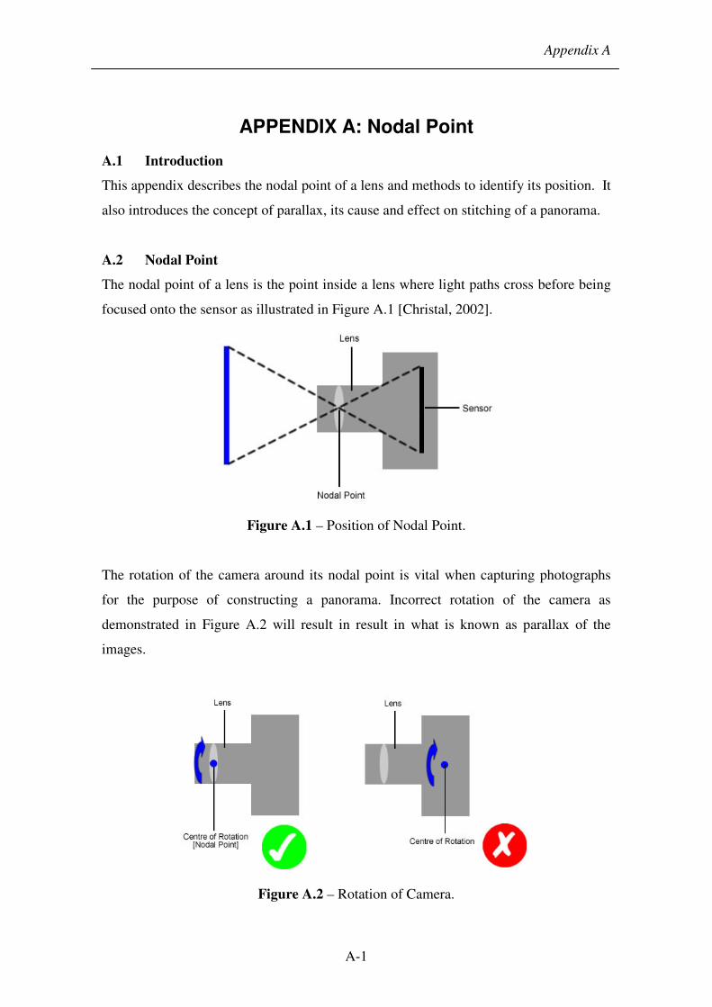
Appendix A
A-1
APPENDIX A: Nodal Point
A.1 Introduction
This appendix describes the nodal point of a lens and methods to identify its position. It
also introduces the concept of parallax, its cause and effect on stitching of a panorama.
A.2 Nodal Point
The nodal point of a lens is the point inside a lens where light paths cross before being
focused onto the sensor as illustrated in Figure A.1 [Christal, 2002].
Figure A.1 – Position of Nodal Point.
The rotation of the camera around its nodal point is vital when capturing photographs
for the purpose of constructing a panorama. Incorrect rotation of the camera as
demonstrated in Figure A.2 will result in result in what is known as parallax of the
images.
Figure A.2 – Rotation of Camera.

Appendix A
A-2
This is an apparent shifting of foreground objects relative to background objects when
you change your point of view position [Christal, 2002]. Figure A.3 illustrates the
effect of parallax on photographs from different viewpoints.
Figure A.3 – Effects of Parallax.
Parallax of images can affect the stitching process of a panorama. An object that
appears in two overlapping photographs will appear to have shifted relative to the
background. As a result, during stitching of these photographs, misalignment of the
objects will occur resulting in blurring or ghosting as it attempts to blend the object’s
shift with the background [Christal, 2002].
As discussed, positioning the rotation of the camera around the nodal point of its lens is
essential when taking photographs for panoramas. However, the nodal point varies
from camera to camera and its position is not indicated by the manufactures. Therefore
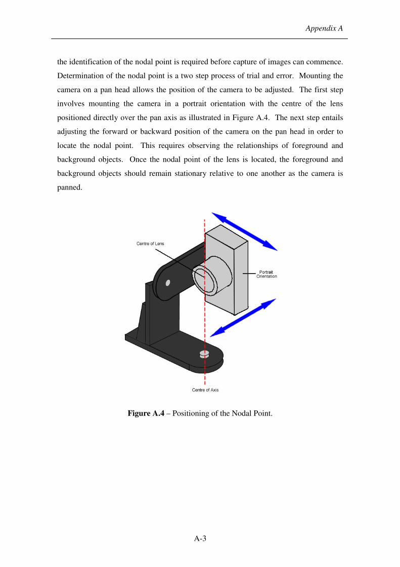
Appendix A
A-3
the identification of the nodal point is required before capture of images can commence.
Determination of the nodal point is a two step process of trial and error. Mounting the
camera on a pan head allows the position of the camera to be adjusted. The first step
involves mounting the camera in a portrait orientation with the centre of the lens
positioned directly over the pan axis as illustrated in Figure A.4. The next step entails
adjusting the forward or backward position of the camera on the pan head in order to
locate the nodal point. This requires observing the relationships of foreground and
background objects. Once the nodal point of the lens is located, the foreground and
background objects should remain stationary relative to one another as the camera is
panned.
Figure A.4 – Positioning of the Nodal Point.

Appendix B
B-1
APPENDIX B: Evaluation of System
B.1 Questionnaire
Figure B.1 – Questionnaire.

Appendix B
B-2
B.2 Structured Interview
The questions posed during the structured interview with each volunteers are shown
below. The questions aim to gather information concerning the current opinions on the
utilisation of digital and traditional photography.
1) PERSONAL DETAILS :
1.1 Name
1.2 E-mail
1.3 Organization
1.4 Area of Expertise
2) DIGITAL AND TRADITIONAL PHOTOGRAPHY
2.1 How many digital camera does your department currently posses?
2.2 Have you ever used digital photography in your area of work? How often?
(Never/Always)
2.3 Do you use digital photography at crime scene or within the laboratory?
2.4 Have you used digital photographs in court?
2.5 Have you encountered any problems with the use of digital photography
2.6 What are the reasons for not using digital photography?
2.7 In comparison to traditional photography, what value do you think digital
photography has in the area of Forensic Science? (No Value/Equal
Value/Greater Value)
2.8 What advantages do you see digital photography providing over the use of
traditional photography that are beneficial to your work?
2.9 Can you see digital photography making traditional photography obsolete?
2.10 How do you see digital photography evolving in your department?
3) CURRENT DOCUMENTATION TECHNIQUES
3.1 Notes, sketches and photography have formed the principle techniques used in
the documentation of a crime scene. Do you consider current documentation
techniques to be adequate to the needs of today’s crime scenes?
(Inadequate/Adequate)

Appendix B
B-3
3.2 Are there any areas of the current crime scene documentation techniques that
require updating?
3.3 Do you consider communicating the relationship between the evidence and its
layout in a scene with current documentation techniques to be: (Very
Difficult/Very Easy)
3.4 Have you experienced any difficulties in attempting to communicate the layout
of the scene in court?
3.5 Visual aids utilized in court are an advantage in communicating complex
information in layman’s terms. Do you: (Strongly Disagree/Strongly Agree)
3.6 Have you used any form of visual aids in court?
3.7 The use of visual aids improves the juror’s concentration and recollection of
the evidence presented to them in court? Do you: (Strongly Disagree/Strongly
Agree)
4) CRIME SCENE RECORDING SYSTEM (CSRS)
4.1 Is there a specific part that makes the portability of the system difficult?
4.2 A compromise between the weight and the sturdiness of a system is often
required. What do you consider of greater value: (Lighter frame/Robust
System)
4.3 What difficulties did you encounter during the setup of the system?
4.4 As with all crime scenes, it is important to document the crime scene as
quickly and thoroughly as possible before subsequent investigation begins and
the crime scene is disturbed. How does the CSRS measure up to current
techniques in terms of the time required to document the crime scene? (Very
Slow/Very Fast)
4.5 Is the time required to capture a scene feasible to employ at a crime scene?
4.6 Can you perceive any type of crime scene that the deployment of the system
would not be appropriate?
4.7 The resultant images from the system provide an overview of the crime scene.
Do you consider this to be: (No Use/Very Useful)
Appendix B
B-4
4.8 Can you see the system becoming a technique to complement current
documentation techniques?
4.9 How accurate does the resultant panorama represent the true crime scene?
(Inaccurate/Accurate)?
4.10 Is the clarity (quality) of the panorama sufficient to accurately depict the
evidence in the crime scene?
4.11 Does navigating the resultant scene produce a feeling of nausea?
4.12 How useful do you think the resultant panorama can be in court as a method of
communicating the layout of the scene? (No Use/Very Useful)
4.13 In comparison to current documentation techniques such as sketches and
photographs, do you consider the system to provide sufficient benefits to
warrant its use in court over as a method to communicate the layout of the
scene?
4.14 Relating evidence to the position it was found in the crime scene can often be
difficult to convey. How useful do you think the CSRS is portraying this
relationship between evidence and the crime scene? (No Use/Very Useful)
4.15 As a case progresses, case information collected over time often builds up to a
unmanageable volume and recollecting a specific piece of information
especially its relevance in a scene may be difficult; more so while giving
evidence. How useful do you think the system is as a method of linking all
case related information into one logical folder? (No Use/Very Useful)
4.16 The deployment of the system in a crime scene may present problems in terms
of contamination of the crime scene or the integrity of the evidence collected;
resulting in failure of the evidence to hold up in court. Can you perceive any
issues which may be of importance?
4.17 Can you see the system being used in your department?
4.18 How much would you envisage a system such as this costing?
4.19 The system uses standard digital camera and low cost equipment therefore
providing a low cost solution in representing a scene. It is the aim of the
project to provide a low cost system where each responding crime unit has
access to the system. How feasible do you think this aim is?
4.20 Do you have any experience or come across other similar systems?

Appendix B
B-5
4.21 Thought on the software interface?
4.22 Thoughts on the Tutorial?

Appendix C
C-1
APPENDIX C: Equipment Specification
C.1 Camera
The specifications of the Canon PowerShot G3 are:
• Image Sensor – 1/1.8 inch CCD.
• Lens – 7.2-28.8 mm.
• Still Image Format – JPEG or RAW.
• Recording Pixels – 2272 × 1704 pixels.
• PC-Connected Shooting – Available.
• Shooting Mode – Program, Shutter-priority (TV), Aperture-priority (AV) and
Manual.
Figure C.1 – Canon PowerShot G3.
C.2 Stage
The stage comprises of several components including the tripod, panoramic head,
motors and circuit box.
C.2.1 Tripod
SLIK U800 Tripod:
• Operating Height - 1.5m
• Weight - 1.5 Kg

Appendix C
C-2
Figure C.1 - SLIK U800 Tripod.
C.2.2 Circuit Box
Connections:
• Motor to Circuit Box - 2 × ‘9’ pin ‘D’ type sockets
• Circuit Box to Computer - USB ‘A’ to ‘B’ Male interface
• Camera to Computer - USB ‘A’ Male to Mini ‘B’ Interface
Circuit Box:
• Battery:
o Type - Lead Acid Rechargeable Battery
o Voltage - 6 Volt,
o 9.5 amp/hr
• Softmark USB Stepper Motor Drive Board:
o Voltage - 12 Volts
o Connection - USB
• Circuitry – Figure C.3.

Appendix C
C-3
Figure C.3 – Circuitry of Circuit Box.
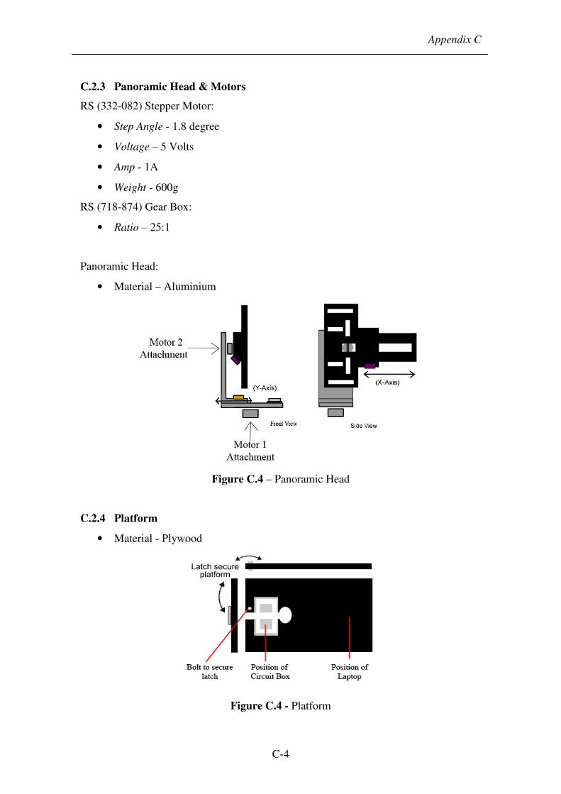
Appendix C
C-4
C.2.3 Panoramic Head & Motors
RS (332-082) Stepper Motor:
• Step Angle - 1.8 degree
• Voltage – 5 Volts
• Amp - 1A
• Weight - 600g
RS (718-874) Gear Box:
• Ratio – 25:1
Panoramic Head:
• Material – Aluminium
Figure C.4 – Panoramic Head
C.2.4 Platform
• Material - Plywood
Figure C.4 - Platform

Appendix C
C-5
C.3 Assembly of System
Figure C.5 – Assembly of System

Appendix C
C-6
Figure C.6 – Photograph of System