Embed Size (px)
Citation preview

CRD - NPA 14/2004Comment Response
(B.) AMC 25.1591
Paragraph 2.
Suggest changing paragraph 2, fourth sub paragraph, first sentence to 'with dry snow (depths below 10 mm)'
The fourth sub paragraph in AMC 25.1591 paragraph 2.0 already refers to recent flight test evidence not taken into account in NPA 14/2004. The evidence provided by TC address the depth to be considered for no contaminant drag and the friction values for dry and wet snow covered runway surfaces. The data provided by TC show that the recommendations in NPA 14/2004 are non conservative. It is advised to revise NPA 14/2004 in line with these data. (see also cmtnr 13)
Comment accepted, text AMC 25.1591 2.0 fourth sub paragraph changed accordingly.
Cmt. 20 / Transport Canada
reason/justificationSuggest changing paragraph 2, fourth sub paragraph, last sentence to “…As an interim measure it has been concluded that it is reasonable to consider these surfaces by recommending that they be addressed by using the data for the lowest depth of the contaminant provided.”See separate comment on paragraph 5.1 Table where it is recommended to set the threshold depth for consideration of contamination drag from dry snow to be 10 mm.See separate comment on paragraph 7.3.1 Table where it is recommended to use the same default friction value for wet and dry snow regardless of depth.
25 October 2005 Page 1 of 28
Comment Response
(B.) AMC 25.1591
Paragraph 5.
Delete: 'Data should assume the contaminant to be uniform in properties and uniformly spread over the complete runway.'
Comment indicate preference not to repeat the assumption in the paragraph 5.1 describing the range of contaminants.
Comment not accepted.
Cmt. 11 / Oslo Airport AS
reason/justificationThis is described under paragraph 3.0 - Standard assumptions, and need not to be duplicated.
Suggest changing paragraph 5.1 Table for the Range of Depth to be considered for Dry Snow to 'Below 10' for No Drag Increase and '10 - 130' for Drag Increase.
The fourth sub paragraph in AMC 25.1591 paragraph 2.0 already refers to recent flight test evidence not taken into account in NPA 14/2004. The evidence provided by TC address the depth to be considered for no contaminant drag and the friction values for dry and wet snow covered runway surfaces. The data provided by TC show that the recommendations in NPA 14/2004 are non conservative. It is advised to revise NPA 14/2004 in line with these data. See also related cmtnr 13 and 20.
Comment accepted, text AMC 25.1591 pragraph 5.1 Table 1 changed accordingly.
Cmt. 21 / Transport Canada
reason/justificationBased the Transport Canada/FAA/NASA/NRC Joint Winter Runway Friction Measurement Program (JWRFMP) Falcon 20 tests on a large number of snow covered surfaces of various depths, it was concluded that contamination drag was negligible below a equivalent depth ofapproximately 0.5 inch for snow of specific gravity of 0.2. This is equivalent to 13 mm.
Using the model of drag for snow defined in the AMC, the effect of different snow depths has been examined for a representative 50-seat regional jet. Under typical conditions (MTOW, SL, -10 deg C), a change in Field Length of 4.2% was calculated with 20 mm dry snow. This figure reduced to 2.6% with 15mm dry snow and 1.4% dry snow.
Based on the above arguments it is recommended that the threshold for drag should be at 10 mm instead of 20 mm.
Table 1 of AMC 25.1591
In Table 1 of the AMC 25.1591, it should be made clear that runways with a slush depth less than 3mm can be considered as a wet runway. This can be accomplished by inserting the same note, i.e., (See Note 1), in the "Range of Depth to be Considered" column, similar to what is done for standing water. Also, the definition of Note 1 should be revised to state "Runways with water or slush depths less than 3 mm ... ."
Comment accepted, text changed AMC 25.1591 pragraph 5.1 Table 1 changed accordingly.
Cmt. 28 / Boeing
reason/justificationApplicants would benefit by clarification of Table 1 noted above.
25 October 2005 Page 2 of 28

Comment Response
(B.) AMC 25.1591
Paragraph 6.
AMC Paragraph 6.2.1
Delete '(but see paragraph 7.4.3)' from the end of this paragraph.
Comment refers to the fact that the reference to paragraph 7.4.3 made at the end of paragraph 6.2.1 in AMC 25.1591 is superfluous. In the context of fixing attention on controllability during operation with contaminated runway surface conditions (see cmtnr 9) it is decided to leave AMC Paragraph 6.2.1 asis.
Comment not accepted.
Cmt. 15 / FAA, USA
reason/justificationThis paragraph says that the performance assumptions remain unchanged from those used for a wet runway. CS 25.109 already allows credit for reverse thrust where available and controllable.
25 October 2005 Page 3 of 28

Comment Response
(B.) AMC 25.1591
Paragraph 7.
7.3.1 Default ValuesThe effective braking coefficient of an anti-skid controlled braked wheel/tyre for a standing water and slush covered runway should be expressed as functions of texture depth.
NPA 14/2004 is based on JAA NPA 25G-334 including the received comments. Explanatory notes to NPA 14/2004 are presented in Part A. Several comments to NPA 14/2004 identify that any reference to recommended future work as given in part D is not included in Part A. Additional clarification will be included in Part A will without changing the intention of the NPA.
CS 25.109 presents two sets of equations defining the maximum tyre-to-ground wet runway braking coefficient depending on the quality (texture) of the runway surface.Higher wet runway braking coefficients may be used for runway surfaces that have been grooved or treated with a porous friction material.
AMC 25.1519 paragraph 7.3.1 Table 2 presents a conservative worst case equation for the braking coefficient for the standing water and slush covered runway, without any credit for the benefits of better quality runways. This approach reflects the consensus view in the FTG. Through cmtnr 4 future work is recommended to define a set of equations reflecting the influence of texture on the braking coefficient for stansing water and slush covered runway.
Additional information is required to substantiate further refinement of the proposed data.Further action is defined based on cmtnr 4. See also comment 12 with suggestion for future supporting data.
The comment is considered for future development outside of the present scope of theNPA.
Cmt. 3 / Oslo Airport AS
reason/justificationIn change 15 of JAR-25.109 a principle was introduced. Two sets of equations defining the maximum tyre-to-ground wet runway braking coefficient are described. The difference between them is the texture. The same principle is valid for the standing water and slush covered runway. The subject should be treated in line with current knowledge. Accordingly the relationship described in 7.3.1 for standing water and slush should be described as equations relating to different texture depth.
As written the equation schedule 'worst case' data for ALL runways and do not seek to take credit for the benefits of better quality runways.
For some states the ESDU data representative for ALL runways do reflect a very conservative distribution with respect to surface texture for runways (See attached SWIFT 2000 pdf.file) which shows the distribution representative for Norwegian runways compared with ESDU ALL runways. This fact highlights the issue even more.
…………SWIFT pdf.file attached in paper version!!
25 October 2005 Page 4 of 28

Comment Response
The limitations with regard to validity for groundspeed V, and contaminant depth for the equation for standing water and slush should be given. The extent of applicability for the equation should be clearly stated.
In considering the maximum depth of runway contaminants it may be necessary to take account of the maximum depth for which the engine air intakes have been shownto be free of ingesting hazardous quantities of water in accordance with CS 25.1091(d)(2). This is added to AMC 25.1591 paragraph 2.0.
No further background information on the equation for the braking coefficient for the standing water and slush covered runway given in AMC 25.1591 paragraph 7.3.1 Table 2 is found.
Comment accepted, additional text added in AMC 25.1591 paragraph 2.0.
Cmt. 7 / Oslo Airport AS
reason/justificationWhat is written in paragraph 2.0, Technical Limitations Data, of this NPA should also be validfor the document itself. If the extent of applicability is not clearly stated, the operators will not be able do so in their own documentation.
'Due to nature of naturally occurring contaminants and difficulties associated with measuring aeroplane performance on such surfaces, any data that is either calculated or measured is subject to limitations with regard to validity. Consequently the extent of applicability should be clearly stated.'
AMC 25.1591 § 7.4.1 ‘minimum V1’
Airbus supports FSG response to UK CAA dissenting opinion, which is mentioned in the original JAA NPA 25G-334 justification. Airbus considers that the possible introduction of VMCG determined on contaminated runways is premature, and should be preceded by appropriate research studies.
Airbus supports the FSG response to the UK CAA dissenting opinion copied below.
FSG Response to UK CAA Dissenting Opinion
The FSG studied this issue in detail and the relevant proposed NPA paragraphs (7.4.1 and 8) are considered to be consistent with accepted practice and the current state of knowledge. There is no agreed method for modifying VMCG values for contaminated runways. The FSG considered a broad range of issues that include those raised by theUK CAA. Accordingly, the above referenced NPA paragraphs include appropriate provisos and cautions that are reflective of the current state of knowledge and that recognise the potential hazards of contaminated runway operations.
Comment noted.
Cmt. 17 / Airbus, France
reason/justification
25 October 2005 Page 5 of 28

Comment Response
Suggest changing paragraph 7.3.1 Table: Contaminant Wet Snow below 5 mm depth, Default Friction Value from 0.20 to 0.17.
Suggest changing paragraph 7.3.1 Table: Contaminant Dry Snow below 10 mm depth, Default Friction Value from 0.20 to 0.17.
Comment provide data collected during the TC/FAA/NASA Joint Winter Runway Friction Measurement Program not supporting using different friction values dependingon the depth of the contaminant proposed in NPA 14/2004. The proposed revision to use a default friction value of 0.17 for wet and dry snow independent of depth is considered conservative.
Comment accepted, text AMC 25.1591 paragraph 7.3.1 Table 2 changed accordingly.
Cmt. 22 / Transport Canada
reason/justificationExisting data collected during the Transport Canada/FAA/NASA Joint Winter Runway FrictionMeasurement Program (JWRFMP) does not support using different braking coefficients for dry snow or wet snow, nor does the data support using a different coefficient depending on the depth. For a representative 50 seat regional jet under typical conditions (MTOW, SL, -10 degC), the change in field length on dry snow is 3.8% using a friction value of 0.20 instead of 0.17. Hence it is not reasonable to provide recommendations which are not conservative, when available suggests otherwise.
Suggest changing fourth sentence to: 'Not withstanding this lack of a common index, the applicant may optionally choose to present take-off and landing performance data as a function of an aeroplane braking coefficient or wheel braking coefficient, constant with groundspeed for runways contaminated with wet snow, dry snow, compacted snow or ice'
Comment provides clarification and brings AMC 25.1591 paragraph 7.3.3 in line with the information provided Table 2.
Comment accepted, text AMC 25.1591 paragraph 7.3.3 changed accordingly.
Cmt. 23 / Transport Canada
reason/justificationThe assumption of a constant coefficient with groundspeed has only been shown to be valid for runways contaminated with snow or ice. For standing water or slush the braking coefficient is dependent on groundspeed as noted in the default value provided in paragraph7.3.1.
Suggest adding the following to 7.4.3 'Unless the applicant can substantiate controllability on a contaminated runway with one engine inoperative and in crosswind conditions, the accelerate stop distance with one engine inoperative should not take credit for reverse thrust.'
Comment address again the importence of controlability aspects associated with operation with contaminated runway surface conditions, which is considered to be outside the scope of the current NPA 14/2004 but cannot be ignored totally for obvious reasons.
This controllability aspect is implicitly covered (and so not neglected) through AMC 25.1591 paragraph 7.4.3. If the applicant decides to take credit for the use of reverse thrust as additional means of deceleration on contaminated runways demonstration of controllability will be subject for discussion with the Authority.
Comment not accepted.
Cmt. 24 / Transport Canada
reason/justificationSince takeoff performance on contaminated runways may well be predicated on accelerate stop distance, the assumption of using reverse thrust following an engine failure neglects the controllability aspects on contaminated runways, particularly in crosswind conditions. Hence it is not a conservative assumption to always permit credit for reverse thrust during an accelerate stop on a contaminated runway following an engine failure.
25 October 2005 Page 6 of 28

Comment Response
AMC 25.1591, Paragraphs 7.3 and 7.3.3
In AMC 25.1591, paragraphs 7.3 and 7.3.3 use the terms "aeroplane braking coefficient" and "wheel braking coefficient." We consider that the "aeroplane braking coefficient" is consistent with the Boeing definition of "airplane braking coefficient," where braking force is equal to the "aeroplane/airplane braking coefficient" times (Weight - Lift); whereas, the "wheel braking coefficient" must be multiplied by the weight on the braked wheels to determine braking force. It is not obvious that everyone who reads this AMC will appreciatethis subtlety, and therefore a definition should be provided. Also, to avoid confusion, the header in Table 2 should be "Default Wheel Friction Value."
Comment requests clarification to the terms used in AMC 25.1591 paragraph 7.3.The explanatory note to Table 2 is considered sufficient to understand that the default fraction values in Table 2 are tyre-to-ground braking coefficients.
Comment not accepted.
Cmt. 29 / Boeing
reason/justificationApplicants would benefit by the clarification noted above.
25 October 2005 Page 7 of 28

Comment Response
(B.) AMC 25.1591
Paragraph 8.
More guidance should be provided relative to CS 25.1591(c) regarding the extent of applicability of the performance data for each contaminant and for when the actual conditions are different from those used to develop the performance information. At least the following four concerns should be addressed:
1. The guidance should clearly state that the definitions of the contaminants used by the applicant should be provided with the performance data. These definitions should be expressed in an operationally useable sense, that is, in terms of easily observable descriptions, not solely in engineering terms. An example would be the definitions providedin the AMC material, but without the references to specific gravity. This information is necessary because there may be other definitions of the contaminants used elsewhere.
2. Although CS 25.1591(c) requires a statement that 'actual conditions that are different from those used in establishing the contaminated runway performance information may leadto different performance', this AMC paragraph (covering what should be stated with the performance data) does not include this statement.
3. Operators should be made aware of the different effects of aquaplaning speed, contaminant type, and contaminant depth on the acceleration and braking ability (i.e., continued takeoff vs. accelerate-stop) used in the performance data. For example, for a given contaminant, additional depth will result in higher drag, but will not affect the braking friction. Therefore, for increasing contaminant depth, the performance data will reflect a reduced acceleration capability, but improved stopping performance.
4. More guidance should be provided for conditions that are different than those used for developing the data. It will be rare that a uniform contaminant covers the entire runway surface to an even depth. Rather than simply acknowledging that performance may be different, more guidance should be provided for selecting the appropriate performance data level to use. An example would be: 'Operators are expected to make careful and conservative judgments in selecting the appropriate performance data to use for operations on contaminated runways. Particular attention should be paid to the presence of any contaminant in the critical high speed portion of the runway. For takeoff, it may be appropriate to use different contaminant types or depths for the takeoff and the accelerate-stop portions. For example, it may be appropriate to use a greater contaminant depth or a contaminant type that has a more detrimental effect on acceleration for the takeoff portion than for the accelerate-stop portion of the takeoff analysis.'
Comment propose to improve the AMC 25.1591 on the subject of completeness.A number of concerns are raised.
Nr 1 address the issue of how to correlate factual information received by the crew with the applicable performance information presented in the AFM. It is noted that e.g. in JAR-OPS the term loose snow is used. Harmoniazition on this issue is recommended but considered outside the scope of NPA 14/2004.
Nr 2 refer to CS 25.1591© and requires a statement to be included in the approved document presenting the performance information for operation with contaminated runway surface conditions. The requirement is clear without need for repeat in the AMC.
Nr 3 address the importance of awareness creation at the operator. Other comments also state the importance of this (see cmtnr 8 and 9). This is considered outside scopeof NPA 14/2004
Nr 4 requests additional guidance to be provided for conditions different than those fordeveloping the performance data. With the current information available this cannot be achieved in reasonable time. To emphasise this issue a general warning is added toAMC 25.1591, paragraph 2.0.
In summary:These comments are considered for future development and discussion outside of the present scope of the NPA.
Cmt. 14 / FAA, USA
reason/justificationCompleteness
25 October 2005 Page 8 of 28

Comment Response
Suggest changing paragraph 8.3, first sub paragraph, last sentence to: 'Operational factors should not be included. However the AFM should contain a clear statement that the data has been prepared with the assumption that appropriate operational factors will be used.'
Justification is presented in Discussion Paper no 35, EASA NPA 14/2004 landing distance on contaminated runways. The proposed revision provides clarification to application of operational factors as required by JAR-OPS or other operating regulations.
Comment accepted, text AMC 25.1591 paragraph 8.3 changed accordingly.
Cmt. 25 / Transport Canada
reason/justificationA recent study (attached) has shown that landing data prepared in accordance with the AMC guidance will not be representative of what would be expected in operational service. The data requires to be factored. However although the current JAR-OPS factor of 1.15 appears to be the minimum acceptable, it may not be conservative. In addition other operating authorities may have different factors. Hence it is recommended that the landing data are provided with no factors but with the proviso that the AFM states that the data are derived with the assumption that appropriate operational factors will be used.
AMC 25.1591, Paragraph 8.3, Takeoff and Landing Data
We suggest deleting or revising the sentence that states:
"Where data is provided for a range of contaminant depths, for example 3, 6, 9. 12, 15 mm,then the AFM should include a statement that interpolation is not permitted"
If interpolation is not permitted, the contaminant depth selected should be conservative.The text is revised in such way that the AFM should indicate how to select contaminant depth, and reads: "Where data is provided for a range of contaminant depths, for example 3, 6, 9, 12, 15mm, then the AFM should clearly indicate how to define data for contaminant depths within the range of contaminant depths provided".
Comment accepted.
Cmt. 30 / Boeing
reason/justificationThe instruction in paragraph 8.3 should not be mandatory. Whether interpolation is or is not permitted should be determined by the manufacturer’s comfort with the interpolation of the data, not a blanket statement.
25 October 2005 Page 9 of 28
Comment Response
(B.) AMC 25.1591
Paragraph 9.
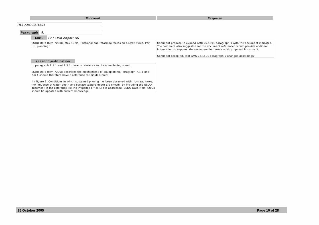
ESDU Data Item 72008, May 1972. 'Frictional and retarding forces on aircraft tyres. Part III: planning.'
Comment propose to expand AMC 25.1591 paragraph 9 with the document indicated.The comment also suggests that the document referenced would provide addional information to support the recommended future work proposed in cmtnr 3.
Comment accepted, text AMC 25.1591 paragraph 9 changed accordingly.
Cmt. 12 / Oslo Airport AS
reason/justificationIn paragraph 7.1.1 and 7.3.1 there is reference to the aquaplaning speed.
ESDU Data Item 72008 describes the mechanisms of aquaplaning. Paragraph 7.1.1 and 7.3.1 should therefore have a reference to this document.
In figure 7, Conditions in which sustained planing has been observed with rib-tread tyres, the influence of water depth and surface texture depth are shown. By including the ESDU document in the reference list the influence of texture is addressed. ESDU Data Item 72008 should be updated with current knowledge.
25 October 2005 Page 10 of 28

Comment Response
A. Explanatory Note
Paragraph -
A 7
As a result of current knowledge the influence of surface texture on contaminants such as standing water and slush are recognized. In the case of wet runways, JAR-25, at change 15 on 1 October 2000, it was expressed as two sets of equations. However, in the case of standing water and slush the consensus view was to prefer to schedule 'worst case' data for ALL runways rather than to seek to take credit for the benefit of better quality runways. It isrecommended that future work address the development of a set of equations reflecting the influence of texture.
NPA 14/2004 is based on JAA NPA 25G-334 including the received comments. Explanatory notes to NPA 14/2004 are presented in Part A. Several comments to NPA 14/2004 identify that any reference to recommended future work as given in part D is not included in Part A. Additional clarification will be included in Part A will without changing the intention of the NPA.
Comment accepted, text Part A paragraph IV 8 added accordingly.Part A paragraph IV 8 identifies the issues for future work and ongoing discussion outside of the present scope of the NPA.
Cmt. 4 / Oslo Airport AS
reason/justificationThe text should reflect the current knowledge. Please see attached e-mail and statement from Ken Balkwill dated December 2004.
As written the NPA does not mention the influence of surface texture.
D 4 (page 25)V (New paragraph at page 4) (Alternatively)
5. Braking friction related to surface texture, standing water and slush.Addressing the influence of surface texture and bringing the subject more in line with current knowledge.
Reference to future work is already addressed in cmtnr 4.
Cmt. 8 / Oslo Airport AS
reason/justificationIf part D of the NPA is not part of what are defined under Explanatory Note with respect to comments, a new section V - Recommended future work should be established in the Explanatory Note.
25 October 2005 Page 11 of 28

Comment Response
A 8 (New paragraph)Operations on contaminated runways are challenging. Operators and operating authorities should consider a classification of skill levels of pilots operating under harsh winter conditions. The FSG acknowledge this as an important issue and address it as a topic under recommended future work
The comment propose to consider a classification of the skill level of pilots operating inwinter conditions. NPA 14/2004 primarily presents performance information for operations with contaminated runway surface conditions. Specific handling (controllability) issues are considered outside the scope of this NPA, allthough the link with controllability is indicated e.g. in AMC 25.1591 7.4.3 and 8.1.3.
The issue of skill level is important but considered outside the scope of the NPA 14/2004.The comment is considered for future development outside the scope of the NPA.
Comment not accepted.
Cmt. 9 / Oslo Airport AS
reason/justificationOperating under harsh winter conditions is a challenging task. Historically operators in northern countries allowed only the most experienced pilots to operate under these conditions. The new concept of operation, open sky, gives another dimension to this type of operations. Guidance material should be developed to help those operators and operating authorities that do not have the experience but now are faced with occasional operations under such harsh winter conditions. (Charterflights).
At the IMAPCR 04 (International Meeting on Aircraft Performance on Contaminated Runways) in Montreal November 2004 there was a presentation from Finnair describing their winter operations. An immediate response from Boeing very strongly addressed that this was an example in accordance with their view, as the aircraft performance allowed was in accordance with the skill level of the pilots.
The issue is an important one and should be reflected in a document describing operations on contaminated runways. To level the 'playground' there should be an agreed classification of demonstrated skill levels. (Example: Experienced, Regular, Occasional).
6. Classification of skill levels for operations under harsh winter conditions.D 4 (page 25)V (New paragraph at page 4) (Alternatively)
Reference to skill levels of pilots operating in winter conditions is already addressed in cmtnr 9.
Cmt. 10 / Oslo Airport AS
reason/justificationLevel the 'playground' and give guidance to operators and operating authorities not used to operations under harsh winter conditions.
If part D of the NPA is not part of what are defined under Explanatory Note with respect to comments, a new section V - Recommended future work should be established in the Explanatory Note.
25 October 2005 Page 12 of 28

Comment Response
Paragraph IV.7 (bottom of page 4)
Quote :FAR 25 does not address performance on contaminated runways so harmonization is not currently a consideration… However, harmonization of this issue will be addressed in the future.Unquote
The comment is clear and self explanatory.
The comment is considered for discussion outside of the present scope of the NPA.
Cmt. 16 / Airbus, France
reason/justificationAirbus is concerned about unilateral introduction of recurring NPAs upgrading certification standards on contaminated runway performance, whereas there is no equivalent FAR standard.
It appears that the FAA has no near term activity planned to harmonize with EASA on this subject.Equal treatment between European and US manufacturers/airlines is therefore questioned.
Airbus would like to have some information on:- EASA position regarding the harmonization with FAA - Schedule of harmonization activity with FAA: date of start and end- Expected date regarding the embodiment of equivalent FAR standard.
25 October 2005 Page 13 of 28

Comment Response
B. Proposals
Paragraph -
AMC Paragraphs 2.0, 4.2, Table 1
Runways contaminated by standing water of a depth less than 3mm are to be considered wet. Dry or wet snow contamination less than 20mm deep or 5mm deep, respectively, is tobe considered as compacted snow. However, no guidance is provided for slush depths less than 3mm deep. It would appear that applicants could use the friction value for slush with no contaminant drag, but this is not specifically stated.
CS 25.1583(k) requires a limitation on the maximum depth of runway contaminants for take-off operation to be furnished. If informationon the effect of runway contaminants on the expected take-off performance is not provided take-off operation should be limited to runways where the degree of contamination does not exceed the equivalent of 3 mm of water. High density slush is considered to be equivalent to water ref e.g. AMC 25.1091(d)(2) precipitation covered runways. However, no clear definition of a wet runway is found in CS 25.
Considering the above slush depths less than 3 mm can be considered also as wet, forwhich AMC 25.1591 is not applicable. Note 1 in AMC Paragraphs 5.1 Table 1 are also applicable in the relevant field in the slush row. See also cmtnr 20, 21 and 28)
Comment accepted, text AMC Paragraphs 5.1 Table 1 changed accordingly.
Cmt. 13 / FAA, USA
reason/justificationConsistency and completeness.
25 October 2005 Page 14 of 28

Comment Response
(B.) CS 25.1591
Paragraph -
Suggest changing paragraph (a), second sentence to 'If supplied, this AFM information must include the expected performance'
In compliance with CS 25.1581(1), the aeroplane flight manual must contain the information required by CS 25.1583 to 25.1587. CS 25.1581(2) refers to other information necessary for safe operation because of design, operating, or handling characteristics. CS 25.1591 is not included but could be considered as information described in CS 25.1581(2). The existing CS 25.1591also refers to an approved document.
This comment assumes that performance information for operation with contaminated runway surface conditions must be provided in the AFM, where the proposed CS 25.1591(b) leaves the option to provide information in an approved document.
Reading AMC 25.1591 paragraph 8.2 may lead to the conclusion that the AFM is the assumed document for presention of the supplementary performance information.
Cmtnr 27 also indicates that NPA 14/2004 is not clear on this issue.
The comment is considered for ongoing discussion outside of the present scope of the NPA.
Cmt. 19 / Transport Canada
reason/justificationAlthough it is implicit in the CS proposal and the AMC, it should be clearly specified that the performance information is to be included in the AFM. This is a change from the existing JAR 25X1591, which did not specify the AFM.
25 October 2005 Page 15 of 28

Comment Response
CS 25.1591 (b) and (c)
CS 25.1591 (b) and (c) state that the performance data must be in an "approved document", whereas AMC 25.1591 paragraph 8.2, implies that the performance data is in the AFM. In light of this, is the "approved document" only the AFM? A clarification of what constitutes an "approved document" is desirable.
The present CS 25.1591(a) states that the supplementaryinformation must be in an approved document, which serves as guidancematerial to assist the operator in developing guidance,recommendations or instructions for use by their flight crews.Furthermore, CS 25.1591(c) states that _if_ the supplementaryinformation appears in the Aeroplane Flight Manual, it must besegregated and clearly distinguished from the normal Flight Manualmaterial.
This clearly means that the term 'approved document' is notrestricted to the AFM, but can be any document approved by EASA.
The revised text for CS 25.1591 as proposed by NPA 14/2004 seemsto express the same intent. In CS 25.1591(a) a new sentence has beenadded which states that if the supplementary information is notsupplied, the AFM must contain a statement prohibiting operation oncontaminated runways. This reference to the AFM in itself does notcontradict the fact that the supplementary information may besupplied in another 'approved document'.
However, the proposed AMC 25.1591 contains many references to theAFM. Although none of these references specifically states that thesupplementary information must be in the AFM, many references makehardly any sense if that is not the case. The proposed text of AMC25.1591 clearly seems to have been written on the assumption that thesupplementary performance information is in the AFM.
Comment is acepted. It needs to be made clear whether thesupplementary information must be in the AFM or may be supplied inanother approved document.
NPA 14/2004 is revised. The proposed text of CS 25.1591 is ammended tochange all references to 'approved document' to 'AFM'. This makes thetext of CS 25.1591 consistent with that of AMC 25.1591 and removesany ambiguities.
Cmt. 27 / Boeing
reason/justificationApplicants would benefit by clarification of what constitutes an "approved document."
25 October 2005 Page 16 of 28

Comment Response
C. Original JAA NPA 25G-334 Proposal Justification
Paragraph -
The dissenting opinion regarding this paragraph, described on page 21 of the NPA, is still fully supported.
In this comment UK CAA presented the dissenting opinion on Paragraph 7.4.1 of the NPA.This issue has been studied in detail by the FSG and the relevant proposed paragraphs7.4.1 and 8 are considered to be consistent with accepted practice and the current state of knowledge. The outcome of the discussion in the FSG is supported by Airbus as indicated in cmtnr 17.
Comment is not accepted.
Cmt. 2 / CAA, UK
reason/justificationParagraph 7.4.1 as presented does not resolve CAA’s concerns.
25 October 2005 Page 17 of 28

Comment Response
GENERAL COMMENT(S)
Paragraph -
LFV Supports NPA. Noted.
Cmt. 1 / LFV Sweden
reason/justification
SLV supports NPA. Noted
Cmt. 1 / SLV, Sweden
reason/justification
I want to comment on the equation for standing water and slush at page 17 in the draft document. (In previous draft document wet snow was also included). This equation does notreflect the influence of surface texture. I believe that surface texture has a significant influence. I believe that the same relationship, following the JAR 25.109 regulation for wet runway, should apply to standing water and slush to. Here there are two sets of equations relating totyre pressure and surface texture.
Information referenced in cmtnr 3 and 4.Noted.
Cmt. 5 / Oslo Airport AS
reason/justification
25 October 2005 Page 18 of 28

Comment Response
The 'AMJ' section of EASA CS 25 is a set of advisory material that constitutes a minimum standard of data and/or methods that aircraft manufacturers may use if they wish to certificate an aircraft for operations on contaminated runways. However, there is nothing to stop the use of superior and more precise data and methods - as is evi-dent from the ESDU References included at the end of the AMJ.Many of the larger companies have their own databases that often link current aircraft to their remote ancestors as designs have evolved within the culture of the specific company. When the opportunity arises, you can be assured that ESDU will seek to include a version of the material that I presented in Canada as Reference material in the AMJ. This version will be in the form of a series of Data Items, which will include both a statement of the methods,and ways in which the methods can be used.Regarding the braking curve for contaminated runways; I understand that this is one such 'default' option chosen from among a collection of curves that are used in vari-ous countries. You are, of course, correct that such relationships should be expressed as functions of texture depth. However, in this case the consensus view was to prefer to schedule 'worst case' data for ALL runways rather than seek to take credit for the benefits of better quality runways. Here, better quality refers to improvements in the depth of the macro-texture
Supplement to cmtnr 3.Noted.
Cmt. 6 / Oslo Airport AS
reason/justification
25 October 2005 Page 19 of 28

Comment Response
Attachment 1 to comments 019 - 025
Issue 111 January 2005
TRANSPORT CANADA AIRCRAFT CERTIFICATION FLIGHT TEST DIVISION
DISCUSSION PAPER NO. 35
EASA NPA 14/2004 LANDING DISTANCE ON CONTAMINATED RUNWAYS
(The Initial Issue of this Discussion Paper, dated 11 January 2005, contains a comparison oflanding distances on contaminated runways determined using the method proposed by EASA NPA 14/2004 with the results from a Monte Carlo Statistical Analysis, and an adaptation (for contaminated runways) of the method contained in FAA AC 121.195(d)-1A.)
1 INTRODUCTION
1.1 General
EASA NPA 14/2004 introduces changes to CS 25.1591 'Performance Information for Operations with Contaminated Runway Surface Conditions', and associated material in AMC 25.1591 'The Derivation and methodology of performance information for use when taking-off and landing with contaminated runway surface conditions'. It is intended that the performance data should be determined for a standardized set of conditions that will generally and conservatively represent the variety of contaminated runway conditions occurring in service.
Paragraph 7 of the AMC describes the effects of contamination on takeoff and landing performance. These effects include contamination displacement and impingement drag, and reduced braking action compared to a bare and dry runway.
For landing, paragraph 7.4.2 of the AMC states that the airborne portion of the landing distance should be calculated by assuming that 7 seconds elapse between passing through the 50 ft screen height and touching down on the runway. In the absence of flight test datato substantiate a lower value, the touchdown speed should be assumed to be 93% of the threshold speed.
Paragraph 8.3 of the AMC states that for speeds higher than VREF, that is speeds up to the recommended approach speed additive to VREF, the associated distances should also be included. Operational factors, as required by JAR-OPS or other operating regulations shouldbe stated as being included or not included.
This paper compares representative results for landing distances obtained using the methodology of EASA NPA 14/2004 with the results from a Monte Carlo Statistical Analysis. In the Monte Carlo method, a landing distance model is established which includes most of the variables that could affect the landing distance on a contaminated runway. Independent random values of each significant operational variable are selected from estimates of the statistical distribution of the variable, and the resulting landing distance is determined. By repeating this calculation a large number of times, the distribution of expected operational landing distances in service may be estimated. From this distribution, the value corresponding to a specified probability of not being exceeded can be determined.
TC discussion paper no. 35 presents representative results for landing distances obtained using the methodology of EASA NPA 14/2004 with results from a Monte Carlostatistical Analysis. The paper also compares representative results for landing distance obtained using the methodology of FAA AC 121.195(d)-1A.
It is concluded that a factor of 1.15 is required to obtain equivalent results between landing distances calculated according to EASA NPA 14/2004 and the Landing distances obtained from the 95% probability results from the Monte Carlo Statistical Analysis.
Even with a 1.15 factor applied to the NPA distances, these distances are still not conservative when compared with the results calculated according to the methodologyof FAA AC 121.195(d)-1A. This is because the FAA AC method specifies an increase inVREF and an increase in the touchdown speed ratio, in addition to the 1.15 factor.
In order to ensure an acceptable level of safety, data produced in accordance with the NPA must be used with appropriate operational factors.
In common with other codes of airworthiness regulations, thelanding distances defined by CS 25 are 'nominal distances' withoutany operational safety factors. This is independent of the conditionof the runway (see CS 25.125 for dry runways, or CS 25.1591 forcontaminated runways). The definitions and calculation methodscontained in the proposed AMC 25.1591 are consistent with thispractice.
Any operational safety factors are prescribed by the operatingregulations in force in the country of origin of the operator.The prevailing regulations governing European operators are JAR-OPS1.
In JAR-OPS 1.515 it is stated that when landing on a dry runway,the aircraft must be able to come to a complete stop within 60% ofthe landing distance available for turbo-jet powered aircraft or 70%of the landing distance available for turbo-propeller poweredaircraft. In other words, the operational factors on dry runways are1.67 for jet aircraft or 1.43 for turboprop aircraft. JAR-OPS1.520(a) prescribes a further factor of 1.15 when the runway is wet,so that the total operational factor becomes 1.92 for jet aircraft or1.64 for turboprop aircraft (applied to the landing distancedetermined on a _dry_ runway!).
For landing on a contaminated runway, which is the subject of theproposed AMC 25.1591, JAR-OPS 1.520(b) specifies a factor of 1.15 tobe applied to the landing distance data on a contaminated runway. Thesame paragraph further states that the required landing distance mustnot be less than that required on a wet runway. So JAR-OPS 1 ensuresthat the operational safety factor on a contaminated runway is neverless than 1.15.
As far as the presentation of landing distance information in theAFM is concerned, AMC 25.1581.6d(18) states that the landing distancemust be presented either directly (i.e. 'nominal distances') or withthe factors required by the operating regulations. CS 25.1587(b)(7)
Cmt. 25 / Transport Canada
25 October 2005 Page 20 of 28

Comment Response
This paper also compares representative results for landing distance obtained using the methodology of FAA AC 121.195(d)-1A. FAA AC 121.195(d)-1A contains a method of establishing operational landing distances on wet runways. This method has been adapted for contaminated runways based on a braking coefficient appropriate to the contaminated surface.
1.2 Table of Contents
1 INTRODUCTION1.1 General1.2 Table of Contents
2 METHODOLOGY2.1 Landing Performance Program Description2.2 Landing Distance Calculation 2.3 AFM Landing Distance2.4 Monte Carlo Statistical Analysis2.5 EASA NPA 14/2004 Method2.6 FAA 121.195(d)-1A Method
3 RESULTS3.1 Sample Aircraft3.2 Sample Flight Conditions3.3 Sample Contaminated Runway Condition3.4 Results Presentation3.5 Comparison of Results3.6 Discussion
4 CONCLUSIONS
Figures 1 to 4
2 METHODOLOGY
2.1 Landing Performance Program Description
As part of an overall program to improve takeoff and landing safety on wet and contaminated runways, Transport Canada Aircraft Certification has developed a Landing Performance Program. This program has been developed using industry standard performance methods. The program contains a Monte Carlo Statistical Analysis option.
The program has been modified to calculate the landing distance on a contaminated runway using the methods of EASA NPA 14/2004 and FAA AC 121.195(d)-1A.
2.2 Landing Distance Calculation
The landing distance is calculated in 4 distinct segments comprised of the threshold offset distance (dzero), the air distance (d1), the transition distance (d2) and the braking distance(d3). These distances are described below.
2.2.1 Threshold Offset Distance (dzero)
This distance is the horizontal distance that the aircraft is assumed to be from the threshold
requires an explanation of the operational landing runway lengthfactors included in the presentation, if appropriate.
Comment is accepted.Commentor is correct in stating that the landing distances on contaminated runways as defined by the proposed AMC 25.1591 inthemselves do not ensure a sufficient level of safety and thatoperational factors have to be applied. Commentor proposes a factorof at least 1.15, which happens to coincide with the requirements ofJAR-OPS 1.520. The responsible authorities in other countries shouldensure that a similar level of safety is achieved by their ownoperating regulations.
It is recommended to treat the landing distances on contaminatedrunways as far as possible in a similar way as the landing distanceson dry runways. This means that the landing distances in AMC25.1591 are defined without factors and that operational factors are prescribed in the applicable operational regulations, and allow the AFM to present the landing distance data either without or with factors included, with proper explanation. NPA 14/2004 paragraph 8.3 is revised accordingly.
25 October 2005 Page 21 of 28

Comment Response
of the runway when the aircraft main wheels are at a height of 50 ft above the runway.
The Threshold Offset Distance is only used in the Monte Carlo Statistical Analysis. It is set to zero for the AFM Landing Distance and the landing distances determined using the NPA and AC.
2.2.2 Air Distance (d1)
This distance is the horizontal distance from the point at which the main wheels are at a height of 50 ft above the runway to the point of main wheel touchdown.
2.2.3 Transition Distance (d2)
The transition distance is defined as the distance between the point of touchdown to a point where the aircraft is in the full braking configuration (i.e. ground attitude, lift dump spoilers extended and full anti-skid braking pressure).
2.2.4 Braking Distance (d3)
The braking distance is defined as the distance between the point at which the aircraft is in the full braking configuration to the point of stop.
This segment can be calculated with no credit for reverse thrust or taking credit for reverse thrust. When credit for reverse thrust is taken, the calculation is based on use of reverse thrust in accordance with operational procedures for the particular aircraft.
2.2.5 Total Distance (landdist)
The total distance is the sum of the segments dzero, d1, d2 and d3. As noted above, the Threshold Offset Distance (dzero) is only used in the Monte Carlo Statistical Analysis.
2.3 AFM Landing Distance
The AFM Landing Distance is the total distance (d1 + d2 + d3), calculated on a dry runway for the given input conditions of weight, altitude and wind.
The input wind is factored by 0.5 for a positive input value (headwind) and by 1.5 for a negative input value (tailwind). The temperature is ISA for the specified altitude, and the runway slope is zero.
The program uses certification test data for each applicable aircraft for all variable parameters needed to determine the air distance, transition distance and the braking distance.
The AFM Landing Distance corresponds to the requirements of FAR 25.125.
2.3.1 Air Distance Calculation
For the AFM Landing Distance, d1 is calculated according to a modified version of the parametric air distance method described in AC 25-7A. The ground speed at 50 ft is calculated from the equivalent airspeed at 50 ft, altitude, temperature and head wind component. The rate of descent at 50 ft is calculated from the ground speed and the glide path. The time from 50 ft to touchdown and the ground speed at touchdown are determined from established relationships with the rate of descent at 50 ft and the rate of descent at touchdown. The distance is then determined by multiplying the average speed
25 October 2005 Page 22 of 28

Comment Response
by the time. The difference from the method described in AC 25-7A is that the parametric relationship is established for ground speed and not true airspeed.
For the AFM Landing Distance, the rate of descent at 50 ft is that appropriate to a 3.5 degree glide path and the rate of descent at touchdown is 8 ft/s.
2.3.2 Transition Distance Calculation
This segment is modeled as a deceleration for a fixed time interval. The distance is calculated from the average groundspeed multiplied by delta time. The deceleration and the time interval are configuration dependent data established from flight tests for each of the specified configurations.
2.3.3 Braking Distance Calculation
Using the braking coefficient for a dry runway, the deceleration is calculated from the net force acting on the aircraft and the distance is calculated by double integration of the deceleration.
There is no credit for reverse thrust in the AFM Landing Distance.
2.4 Monte Carlo Statistical Analysis
The Monte Carlo Statistical Analysis is based on the same landing distance model as the AFM Landing Distance. However each parameter in the landing distance model can be independently randomly varied in accordance with specified statistical distributions and the resulting landing distance determined. By running the model a large number of times, the distribution of landing distances can be determined.
The landing distance, which will not be exceeded with a specified probability, can be calculated from the landing distance distribution. The results in this paper are presented in terms of the 95% probability value.
2.4.1 Distribution of Landing Distance Parameters
The distributions of the significant variable parameters affecting the landing distance used inthe Monte Carlo Statistical Analysis are listed below:
(a) Weight. To account for variability in weight, the input value is multiplied by a weight factor. Since aircraft weight is directly accounted for in the input, the expected variability islimited to errors in the estimation of weight at landing. The mean value is unity, the standard deviation is 0.5% of the estimated landing weight and the minimum and maximumvalues are -/+ 3 standard deviations.
(b) Pressure Altitude. To account for variability in pressure altitude, an increment is added to the input value. Since altitude is directly accounted for in the input, the expected variability is limited to errors in the estimation of pressure altitude at the landing airport. The mean value is zero, the standard deviation is 300 ft and the minimum and maximum values are -1000/+ 1000 ft.
(c) Temperature. To account for variability in temperature, an increment is added to the ISA value for the input pressure altitude. The expected variability covers the operational temperature range for winter-contaminated runways. This requires that the increment be a
25 October 2005 Page 23 of 28

Comment Response
function of the pressure altitude. The mean value of the increment is chosen to give a temperature of -10 oC (e.g. the increment from ISA is -25 oC at Sea Level). The standard deviation is 10 oC. The minimum value is -3 standard deviations (i.e. -40 oC) and the maximum value is + 2 standard deviations (i.e. +10 oC).
(d) Runway slope. The expected variability covers the operational runway slope range approved for the aircraft. The mean value is zero, the standard deviation is a gradient of 0.5% and the minimum and maximum values are -2 %/+2 %.
(e) Headwind at 10 m. To account for variability in the reported headwind, an increment is added to the input value (without factoring). The mean value is zero and the standard deviation is 0.25 multiplied by the input headwind value, but not less than 1.25 knots. The minimum and maximum values are -/+ 3 standard deviations.
(f) Threshold offset distance. Due to variability in the distance from the runway threshold tothe point at which the aircraft is 50 ft above the runway, a threshold offset distance is added to the landing distance from 50 ft. The mean value is zero, the standard deviation is 100 ft and the minimum and maximum values are -300 ft/+300 ft.
(g) Equivalent airspeed at 50 ft (V50). An increment is added to VREF to account for standard operating procedures and atmospheric conditions. The mean value of this increment is 50% of the reported headwind but not less than 5 knots. The standard deviation is 50% of the mean value and the minimum and maximum are 0/+20 knots.
(h) Glide path at 50 ft. The mean value is 3 deg. The standard deviation is 0.2 deg and theminimum and maximum values are +2.5/+3.5 deg.
(i) Touchdown rate of descent. The mean value is 3 ft/s. The standard deviation is 2 ft/s and the minimum and maximum values are +1/+6 ft/s.
(j) Transition segment delta time. To account for variability in the time delay from main wheel touchdown to full braking configuration, an increment is added to the certification value. This increment is more typical of normal pilot response in de-rotating the aircraft and applying maximum braking. The mean value of the increment is 1 s, the standard deviation is 1 s and the minimum and maximum values are 0/+4 s.
(k) Transition segment deceleration. To account for variability in deceleration during the transition time delay, the certification value is multiplied by a factor. This factor would be expected to be slightly lower in operational service than that obtained during certification tests. The mean value is 0.9, the standard deviation is 0.1 and the minimum and maximumvalues are -/+ 3 standard deviations.
(l) Idle thrust. To account for variability in idle thrust during the braking segment, the certification value is multiplied by a factor. In operational service, the idle thrust could be expected to be either higher or lower than the value used in certification. The mean value is unity, the standard deviation is 0.1 and the minimum and maximum values are -/+ 3 standard deviations.
(m) Contaminated runway braking coefficient. To account for variability in the contaminated runway braking coefficient, the mean value is multiplied by a factor. The reference value of the factor is unity, the standard deviation is 0.15 and the minimum and maximum values are -/+ 3 standard deviations.
(n) Reverse thrust selection delta time. To account for variability in the time delay from fullbraking to reverse thrust selection, an increment is added to the certification value. This increment is more typical of normal pilot response than that used in certification testing.
25 October 2005 Page 24 of 28

Comment Response
The mean value is 1 s, the standard deviation is 1 sec and the minimum and maximum values are 0/+4 s.
(o) Reverse thrust. The Monte Carlo calculation is done without credit for reverse thrust and with credit for reverse thrust. To account for variability in reverse thrust, the certification value is multiplied by a factor. In operational service, the reverse thrust could be expected to be either higher or lower than the value used in certification. The mean value is unity, the standard deviation is 0.1 and the minimum and maximum values are -/+ 3 standard deviations.
2.5 EASA NPA 14/2004 Method
The NPA distance is the total distance (d1 + d2 + d3), calculated on a contaminated runwayfor the given input conditions of weight, altitude and wind.
The input wind is factored by 0.5 for a positive input value (headwind) and by 1.5 for a negative input value (tailwind). The temperature is ISA for the specified altitude, and the runway slope is zero.
2.5.1 Air Distance
The air distance (d1) is calculated assuming an air time between 50 ft and touchdown of 7 seconds. The touchdown speed is 0.93 of the true groundspeed at 50 ft (i.e. it is assumedthat the speed loss in the landing flare is an inertial speed loss).
2.5.2 Transition Distance
For the transition distance, the AFM Landing Distance model is used with the touchdown speed derived as above.
2.5.3 Braking Distance
For the braking distance, the AFM Landing Distance model is used with the speed at the start of the braking segment derived as above. The braking segment is calculated using thespecified effective braking coefficient. There is no credit taken for any drag due to the contaminant.
The braking distance is calculated without credit for reverse thrust and with credit for reverse thrust.
2.6 FAA 121.195(d)-1A Method
The FAA AC distance is the total distance (d1 + d2 + d3), calculated on a contaminated runway for the given input conditions of weight, altitude and wind, multiplied by a factor of 1.15.
The input wind is factored by 0.5 for a positive input value (headwind) and by 1.5 for a negative input value (tailwind). The temperature is ISA for the specified altitude, and the runway slope is zero.
2.6.1 Air Distance
The air distance (d1) is calculated assuming an air time between 50 ft and touchdown of thelonger of 7 seconds or the AFM Landing Distance air time + 2 seconds.
25 October 2005 Page 25 of 28

Comment Response
The FAA AC specifies the airspeed at 50 ft to be 1.4VSO. The minimum value of the landingreference speed for the determination of the AFM Landing Distance, VREF, is 1.3VSO. The choice of 1.4VSO is considered to more accurately represent operational landing speeds.
However not all aircraft utilize the minimum value for VREF. In addition, most recently certified aircraft have a minimum value based on 1.23 VS1g instead of 1.3VSO. Hence in this study, the airspeed at 50 ft has been calculated from VREF * (1.4/1.3).
The touchdown speed specified by the FAA AC is 0.96 of the true groundspeed at 50 ft (i.e. it is assumed that the speed loss in the landing flare is an inertial speed loss).
2.6.2 Transition Distance
For the transition distance, the AFM Landing Distance model is used with the touchdown speed derived as above.
2.6.3 Braking Distance
For the braking distance, the AFM Landing Distance model is used with the speed at the start of the braking segment derived as above. The braking segment is calculated using thespecified effective braking coefficient. There is no credit taken for any drag due to the contaminant.
The braking distance is calculated without credit for reverse thrust and with credit for reverse thrust. 3 RESULTS
3.1 Sample Aircraft
In order to compare the methodology, four sample aircraft have been used in this study. The main characteristics are described below.
Table 1Main Characteristics of Turbojets Used in Study Turbojet Identifier Type Max Landing Weight (MLW) (lbf) VREF at MLW (KEAS)A 50 seat regional jet 47000 142B 70 seat regional jet 67000 136C Large business jet 78600 132D Small business jet 33750 126
3.2 Sample Flight Conditions
Twelve sample flight conditions have been chosen as follows:
(a) 2 weights (Maximum Landing Weight (MLW) and 0.75 * MLW
(b) 2 altitudes (Sea Level (SL) and 5000 ft)
(c) 3 headwind components (Calm, 20 knots headwind and 5 knots tailwind).
3.3 Sample Contaminated Runway Condition
25 October 2005 Page 26 of 28

Comment Response
For this study, the contaminated runway was covered by dry snow. No credit was taken for any contamination drag. As specified in the NPA, the mean wheel braking coefficient was 0.17 (without any further factoring due to anti-skid operation).
3.4 Results Presentation
The results are presented in terms of landing distance factors. The Monte Carlo Statistical Analysis results are presented in terms of the distance which will not be exceeded with a 95% probability, divided by the AFM Landing Distance. The NPA and AC factors are the calculated distance divided by the AFM Landing Distance.
The factors are plotted against the AFM Landing Distance for each aircraft/flight condition combination (48 points).
3.5 Comparison of Results
Figure 1 shows the Monte Carlo 95% factors together with the factors calculated by NPA and the AC, without credit for reverse thrust. Figure 2 shows the Monte Carlo 95% factors together with the factors calculated by NPA and the AC, with credit for reverse thrust.
In general, it can be seen that the factors predicted by the NPA are considerably lower than the Monte Carlo 95% factors whereas the factors calculated by the AC are higher.
There are several reasons why the factors calculated by the AC are considerably higher thanthose calculated by the NPA: the increased speed assumed at 50 ft, the increase in touchdown speed ratio and the 1.15 factor.
Figures 3 (no reverse) and 4 (with reverse) show the same Monte Carlo and FAA AC results but with the NPA factors multiplied by 1.15. In general, the NPA results, with the 1.15 factor, are very similar to the Monte Carlo results.
3.6 Discussion
It is clear from above that the landing distance calculated in accordance with the NPA guidance will not be representative of that which would be expected in operational service. Although the NPA guidance states that information on the effects of higher speeds than VREF should be included, it is unclear how it is intended to use this information.
The NPA guidance states that operational factors, as required by JAR-OPS or other regulating regulations, should be stated as being included or not included. As indicated by the results in this paper, the current JAR-OPS factor of 1.15 should be considered a minimum acceptable value and a greater factor may be justified.
The data produced in accordance with the NPA guidance will likely be used in other jurisdictions, including Canada, where similar operational factors are not in place. Hence it is recommended that the data be provided without operational factors and that the AFM contains a proviso that the data are derived on the assumption that appropriate operational factors will be used. 5 CONCLUSIONS
The landing distances calculated according to EASA NPA 14/2004 and speed of VREF are notconservative compared to the 95% probability results from the Monte Carlo Statistical
25 October 2005 Page 27 of 28

Comment Response
Analysis. A factor of 1.15 is required to obtain equivalent results.
Even with a 1.15 factor applied to the NPA distances, these distances are still not conservative when compared with the results calculated according to the methodology of FAA AC 121.195(d)-1A. This is because the FAA AC method specifies an increase in VREF and an increase in the touchdown speed ratio, in addition to the 1.15 factor.
In order to ensure an acceptable level of safety, data produced in accordance with the NPA must be used with appropriate operational factors.
reason/justification
ACG Supports NPA. Noted.
Cmt. 26 / ACG, Austria
reason/justification
25 October 2005 Page 28 of 28


![Annex to CRD to NPA 2014-29(A) - EASA · 2017-06-29 · 2 of 307 Table of Contents ANNEX I..... 17 [PART-FCL] ..... 17 SUBPART A..... 17](https://img.pdfslide.net/doc/110x75/5e6b359dd8262457a41ad9af/annex-to-crd-to-npa-2014-29a-easa-2017-06-29-2-of-307-table-of-contents-annex.jpg)