Embed Size (px)
Citation preview
7-1
C h a p t e r 7
Creating a 3D Assembly Drawing
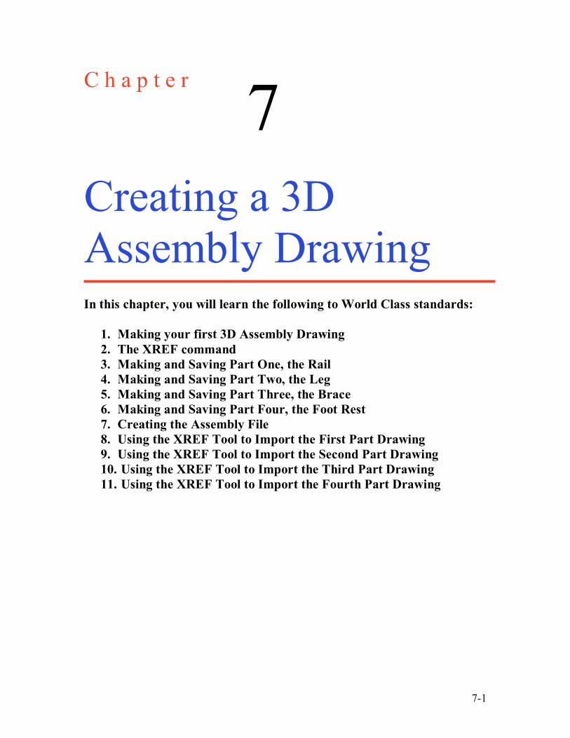
In this chapter, you will learn the following to World Class standards:
1. Making your first 3D Assembly Drawing 2. The XREF command 3. Making and Saving Part One, the Rail 4. Making and Saving Part Two, the Leg 5. Making and Saving Part Three, the Brace 6. Making and Saving Part Four, the Foot Rest 7. Creating the Assembly File 8. Using the XREF Tool to Import the First Part Drawing 9. Using the XREF Tool to Import the Second Part Drawing 10. Using the XREF Tool to Import the Third Part Drawing 11. Using the XREF Tool to Import the Fourth Part Drawing
7-2
Making Your First Assembly Drawing ________________________________________________________ In the world of three dimensional computer aided design, you concatenate a group of solid parts, bringing them together into a collection of joining components to create a single product. Today, this newer system of design is replacing the older and antiquated two-dimensional layout. The fresher arrangement of virtual apparatus allows the designer to examine interfaces between parts and look for interferences. With the ability to add material and lighting, you can inspect the assembly for cosmetic appearance as well. If developing solid parts in the earlier chapters� added inspiration to your professional character, and generating multiple orthographic views in seconds gave you a sense of modern day efficiency, then for any true designer, the ability to create an inexpensive and complex assembly is breathtaking. An architect or engineer who has control of the 3D assembly technology in a small electronic box and display otherwise known as a computer can now feel they are in the driver�s seat in the design process. In the history of assembly drawings, such as those originated by Leonardo Da Vinci, hand drawn artistic renderings were penciled to portray assemblies such as a church or defensive works. Closer to your period, in the 20th century, layout drawings would show each part to half or full scale to identify the fits between objects. Once two-dimensional computer aided design systems were utilized, many of the similar processes used in the previous centuries proved adequate until three-dimensional modeling came on the seen.
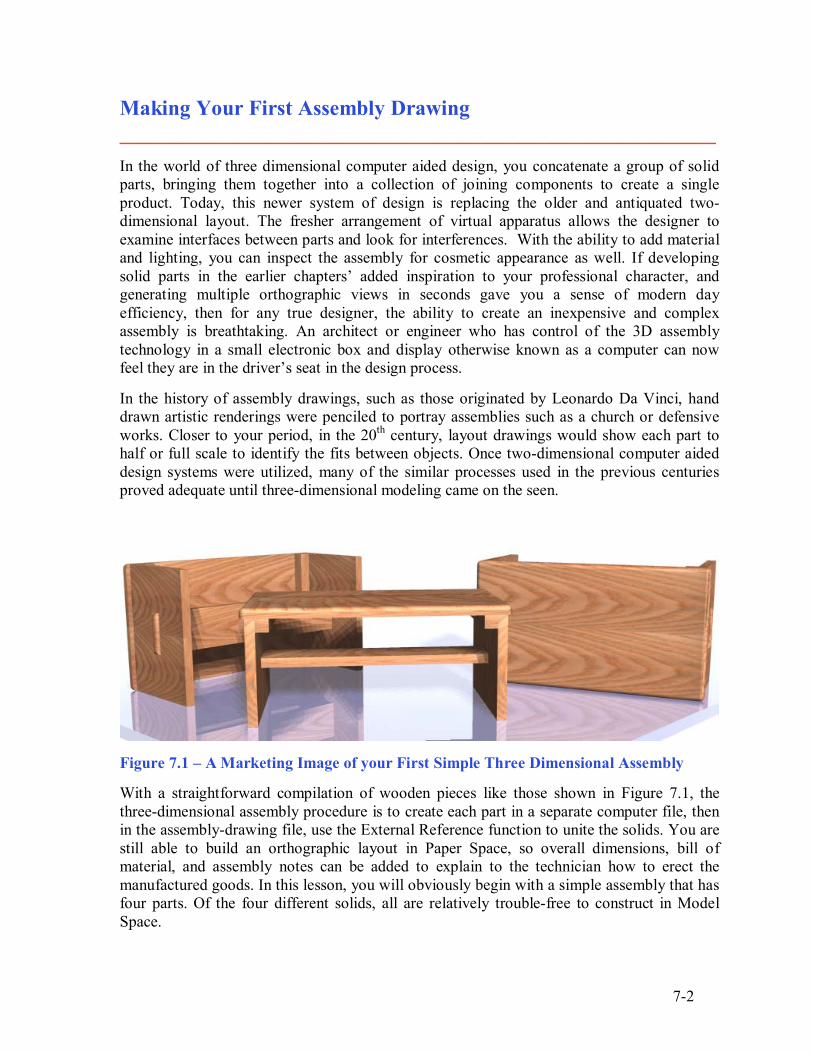
Figure 7.1 � A Marketing Image of your First Simple Three Dimensional Assembly With a straightforward compilation of wooden pieces like those shown in Figure 7.1, the three-dimensional assembly procedure is to create each part in a separate computer file, then in the assembly-drawing file, use the External Reference function to unite the solids. You are still able to build an orthographic layout in Paper Space, so overall dimensions, bill of material, and assembly notes can be added to explain to the technician how to erect the manufactured goods. In this lesson, you will obviously begin with a simple assembly that has four parts. Of the four different solids, all are relatively trouble-free to construct in Model Space.
7-3
The XREF Command ________________________________________________________ The concept of using a drawing reference versus a drawing block is very important when beginning to use the AutoCAD modeling system to build assemblies. Imagine a house with thousands of components. If you insert the file using copy and paste or the insert block function, the solid enters into the home assembly with all the part�s computer definitions, which existed in the individual part-drawing file. After adding multiple pieces into the assembly drawing, the computer file size will show an enormous quantity of bytes. In other words, as you construct the virtual house in Model Space, periodically check the properties of the computer file and soon you have an enormous 10-Megabyte drawing that is slowing your Personal Computer down dramatically.
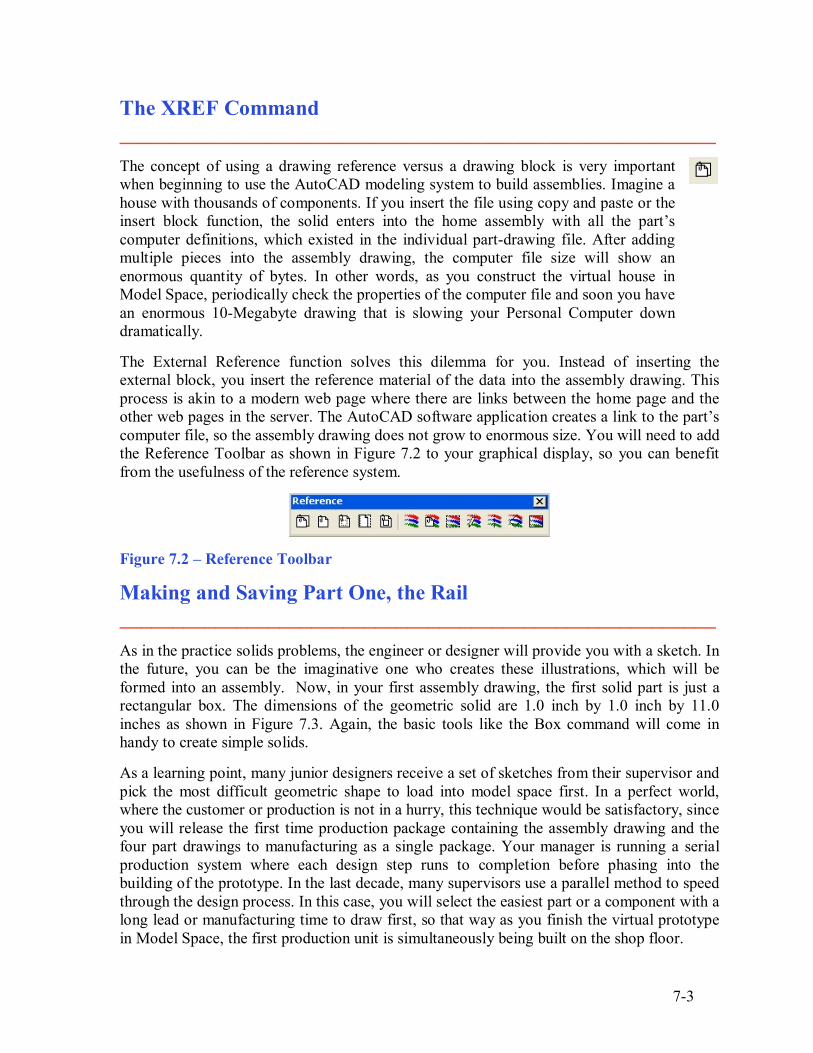
The External Reference function solves this dilemma for you. Instead of inserting the external block, you insert the reference material of the data into the assembly drawing. This process is akin to a modern web page where there are links between the home page and the other web pages in the server. The AutoCAD software application creates a link to the part�s computer file, so the assembly drawing does not grow to enormous size. You will need to add the Reference Toolbar as shown in Figure 7.2 to your graphical display, so you can benefit from the usefulness of the reference system.
Figure 7.2 � Reference Toolbar
Making and Saving Part One, the Rail ________________________________________________________ As in the practice solids problems, the engineer or designer will provide you with a sketch. In the future, you can be the imaginative one who creates these illustrations, which will be formed into an assembly. Now, in your first assembly drawing, the first solid part is just a rectangular box. The dimensions of the geometric solid are 1.0 inch by 1.0 inch by 11.0 inches as shown in Figure 7.3. Again, the basic tools like the Box command will come in handy to create simple solids. As a learning point, many junior designers receive a set of sketches from their supervisor and pick the most difficult geometric shape to load into model space first. In a perfect world, where the customer or production is not in a hurry, this technique would be satisfactory, since you will release the first time production package containing the assembly drawing and the four part drawings to manufacturing as a single package. Your manager is running a serial production system where each design step runs to completion before phasing into the building of the prototype. In the last decade, many supervisors use a parallel method to speed through the design process. In this case, you will select the easiest part or a component with a long lead or manufacturing time to draw first, so that way as you finish the virtual prototype in Model Space, the first production unit is simultaneously being built on the shop floor.
7-4
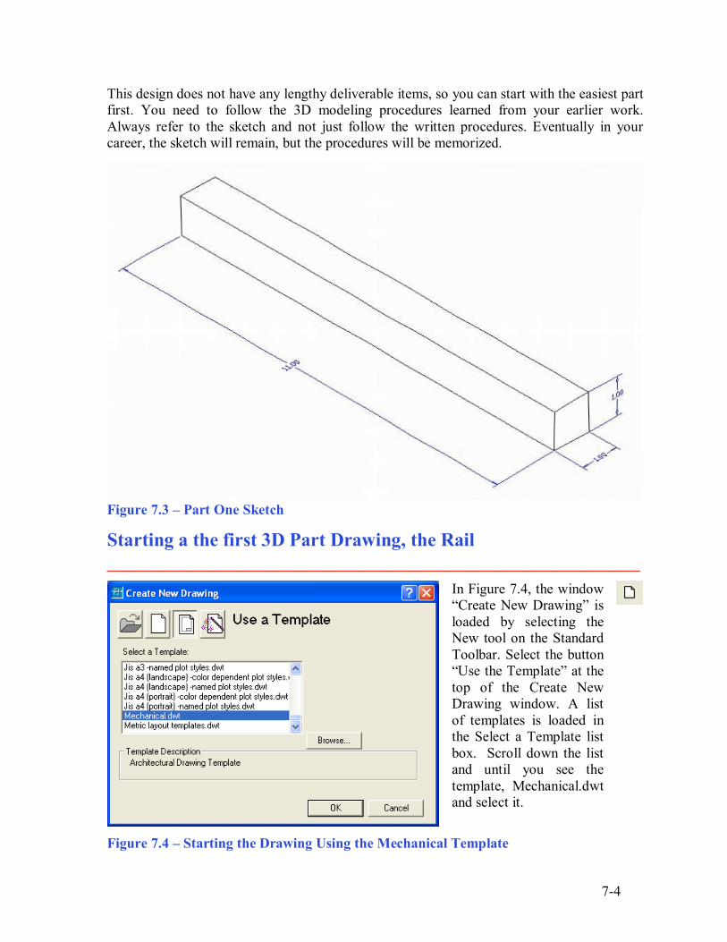
This design does not have any lengthy deliverable items, so you can start with the easiest part first. You need to follow the 3D modeling procedures learned from your earlier work. Always refer to the sketch and not just follow the written procedures. Eventually in your career, the sketch will remain, but the procedures will be memorized.
Figure 7.3 � Part One Sketch
Starting a the first 3D Part Drawing, the Rail ________________________________________________________
In Figure 7.4, the window �Create New Drawing� is loaded by selecting the New tool on the Standard Toolbar. Select the button �Use the Template� at the top of the Create New Drawing window. A list of templates is loaded in the Select a Template list box. Scroll down the list and until you see the template, Mechanical.dwt and select it.
Figure 7.4 � Starting the Drawing Using the Mechanical Template
7-5
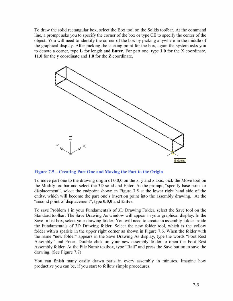
To draw the solid rectangular box, select the Box tool on the Solids toolbar. At the command line, a prompt asks you to specify the corner of the box or type CE to specify the center of the object. You will need to identify the corner of the box by picking anywhere in the middle of the graphical display. After picking the starting point for the box, again the system asks you to denote a corner, type L for length and Enter. For part one, type 1.0 for the X coordinate, 11.0 for the y coordinate and 1.0 for the Z coordinate.
Figure 7.5 � Creating Part One and Moving the Part to the Origin
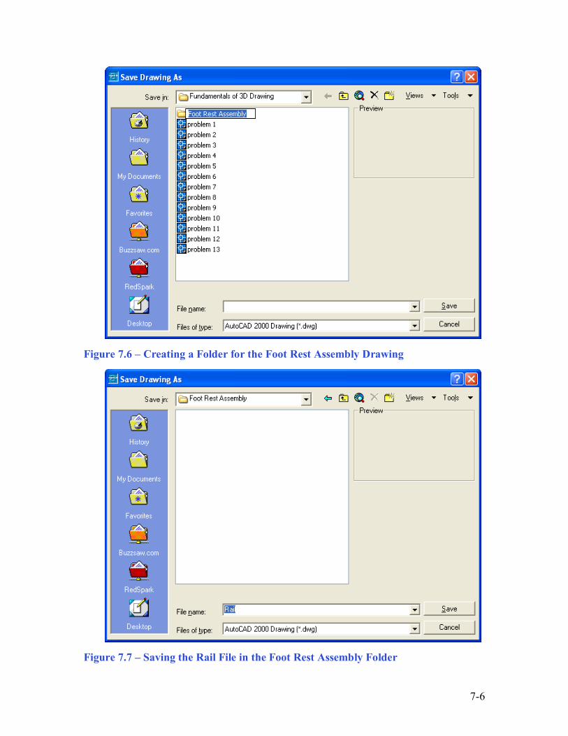
To move part one to the drawing origin of 0,0,0 on the x, y and z axis, pick the Move tool on the Modify toolbar and select the 3D solid and Enter. At the prompt, �specify base point or displacement�, select the endpoint shown in Figure 7.5 at the lower right hand side of the entity, which will become the part one�s insertion point into the assembly drawing. At the �second point of displacement�, type 0,0,0 and Enter. To save Problem 1 in your Fundamentals of 3D Drawing Folder, select the Save tool on the Standard toolbar. The Save Drawing As window will appear in your graphical display. In the Save In list box, select your drawing folder. You will need to create an assembly folder inside the Fundamentals of 3D Drawing folder. Select the new folder tool, which is the yellow folder with a sparkle in the upper right corner as shown in Figure 7.6. When the folder with the name �new folder� appears in the Save Drawing As display, type the words �Foot Rest Assembly� and Enter. Double click on your new assembly folder to open the Foot Rest Assembly folder. At the File Name textbox, type �Rail� and press the Save button to save the drawing. (See Figure 7.7) You can finish many easily drawn parts in every assembly in minutes. Imagine how productive you can be, if you start to follow simple procedures.
7-6
Figure 7.6 � Creating a Folder for the Foot Rest Assembly Drawing
Figure 7.7 � Saving the Rail File in the Foot Rest Assembly Folder
7-7
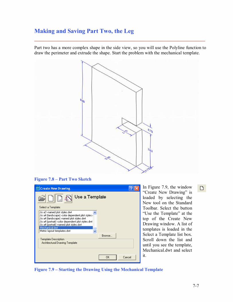
Making and Saving Part Two, the Leg ________________________________________________________ Part two has a more complex shape in the side view, so you will use the Polyline function to draw the perimeter and extrude the shape. Start the problem with the mechanical template.
Figure 7.8 � Part Two Sketch
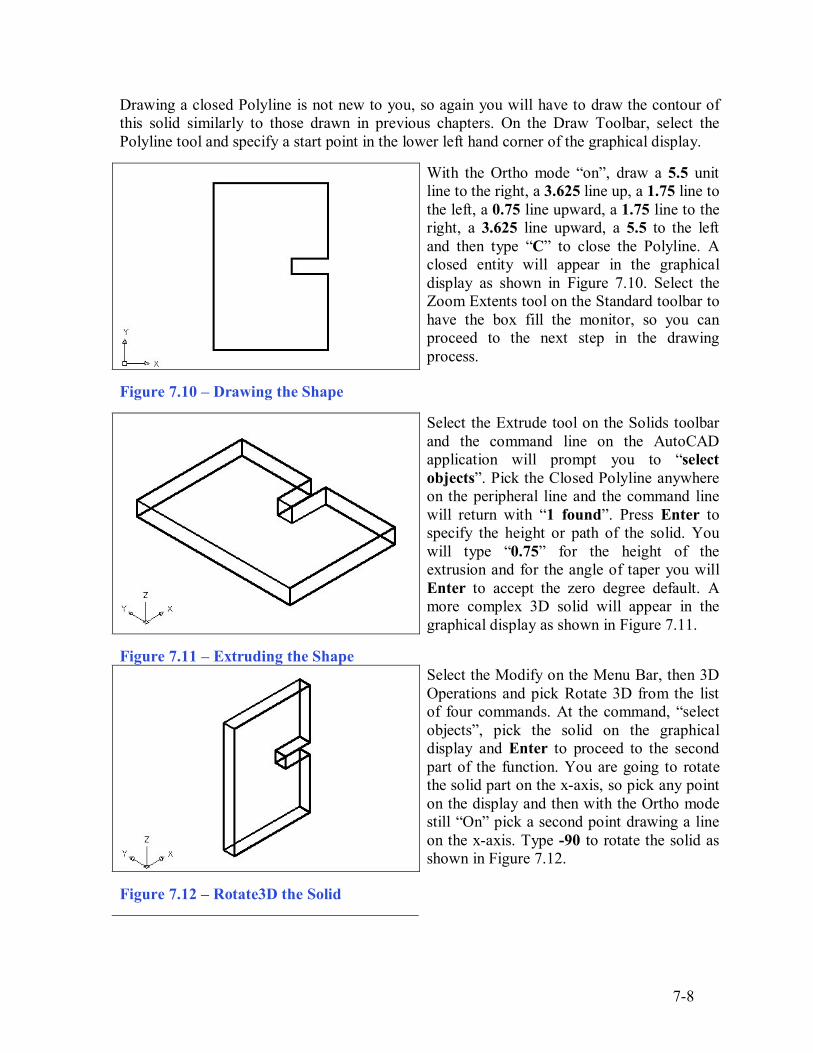
In Figure 7.9, the window �Create New Drawing� is loaded by selecting the New tool on the Standard Toolbar. Select the button �Use the Template� at the top of the Create New Drawing window. A list of templates is loaded in the Select a Template list box. Scroll down the list and until you see the template, Mechanical.dwt and select it.
Figure 7.9 � Starting the Drawing Using the Mechanical Template
7-8
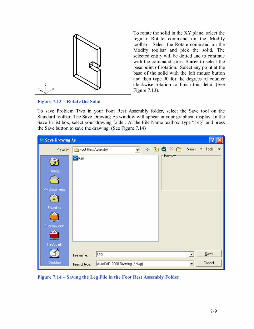
Drawing a closed Polyline is not new to you, so again you will have to draw the contour of this solid similarly to those drawn in previous chapters. On the Draw Toolbar, select the Polyline tool and specify a start point in the lower left hand corner of the graphical display.
With the Ortho mode �on�, draw a 5.5 unit line to the right, a 3.625 line up, a 1.75 line to the left, a 0.75 line upward, a 1.75 line to the right, a 3.625 line upward, a 5.5 to the left and then type �C� to close the Polyline. A closed entity will appear in the graphical display as shown in Figure 7.10. Select the Zoom Extents tool on the Standard toolbar to have the box fill the monitor, so you can proceed to the next step in the drawing process.
Figure 7.10 � Drawing the Shape
Select the Extrude tool on the Solids toolbar and the command line on the AutoCAD application will prompt you to �select objects�. Pick the Closed Polyline anywhere on the peripheral line and the command line will return with �1 found�. Press Enter to specify the height or path of the solid. You will type �0.75� for the height of the extrusion and for the angle of taper you will Enter to accept the zero degree default. A more complex 3D solid will appear in the graphical display as shown in Figure 7.11.
Figure 7.11 � Extruding the Shape
Select the Modify on the Menu Bar, then 3D Operations and pick Rotate 3D from the list of four commands. At the command, �select objects�, pick the solid on the graphical display and Enter to proceed to the second part of the function. You are going to rotate the solid part on the x-axis, so pick any point on the display and then with the Ortho mode still �On� pick a second point drawing a line on the x-axis. Type -90 to rotate the solid as shown in Figure 7.12.
Figure 7.12 � Rotate3D the Solid
7-9
To rotate the solid in the XY plane, select the regular Rotate command on the Modify toolbar. Select the Rotate command on the Modify toolbar and pick the solid. The selected entity will be dotted and to continue with the command, press Enter to select the base point of rotation. Select any point at the base of the solid with the left mouse button and then type 90 for the degrees of counter clockwise rotation to finish this detail (See Figure 7.13).
Figure 7.13 � Rotate the Solid
To save Problem Two in your Foot Rest Assembly folder, select the Save tool on the Standard toolbar. The Save Drawing As window will appear in your graphical display. In the Save In list box, select your drawing folder. At the File Name textbox, type �Leg� and press the Save button to save the drawing. (See Figure 7.14)
Figure 7.14 � Saving the Leg File in the Foot Rest Assembly Folder
7-10
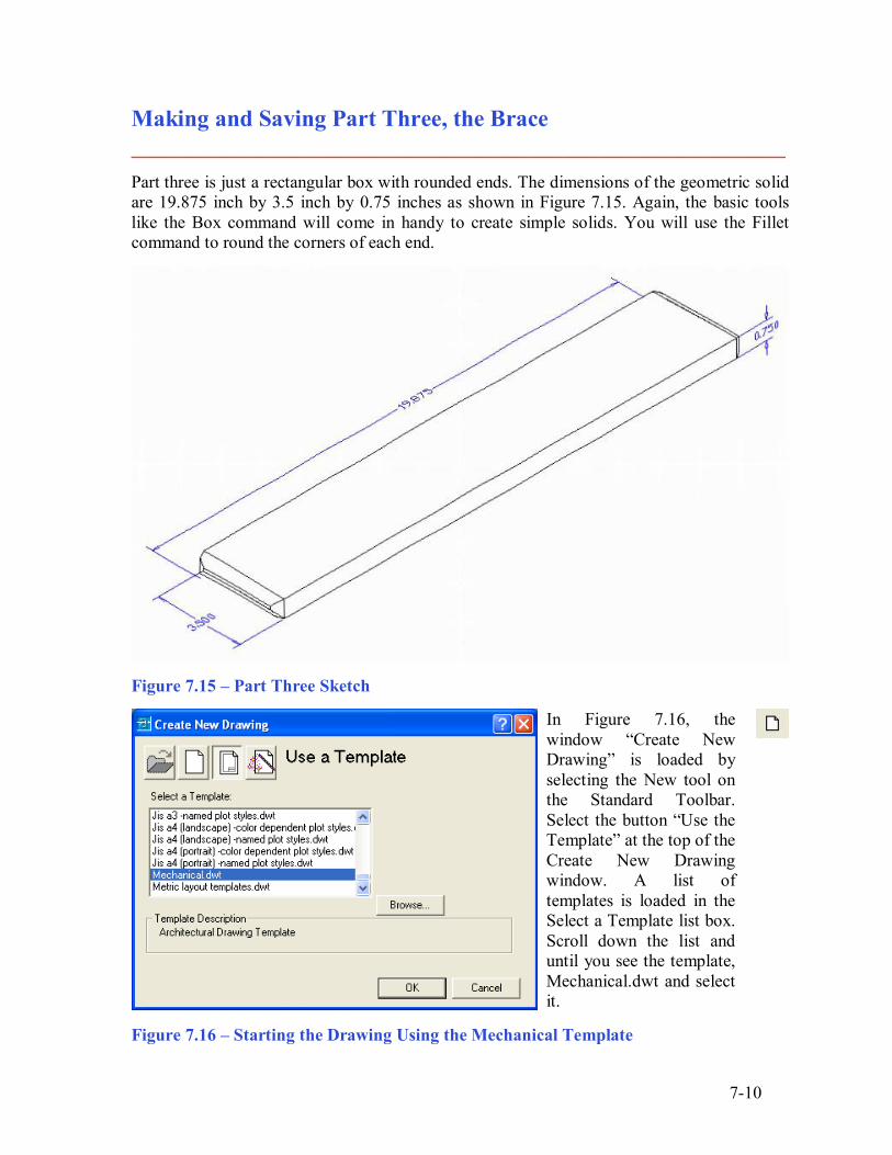
Making and Saving Part Three, the Brace ________________________________________________________ Part three is just a rectangular box with rounded ends. The dimensions of the geometric solid are 19.875 inch by 3.5 inch by 0.75 inches as shown in Figure 7.15. Again, the basic tools like the Box command will come in handy to create simple solids. You will use the Fillet command to round the corners of each end.
Figure 7.15 � Part Three Sketch
In Figure 7.16, the window �Create New Drawing� is loaded by selecting the New tool on the Standard Toolbar. Select the button �Use the Template� at the top of the Create New Drawing window. A list of templates is loaded in the Select a Template list box. Scroll down the list and until you see the template, Mechanical.dwt and select it.
Figure 7.16 � Starting the Drawing Using the Mechanical Template
7-11
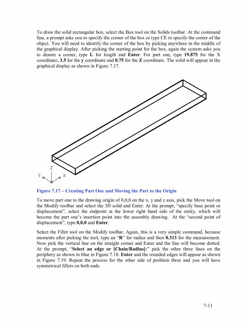
To draw the solid rectangular box, select the Box tool on the Solids toolbar. At the command line, a prompt asks you to specify the corner of the box or type CE to specify the center of the object. You will need to identify the corner of the box by picking anywhere in the middle of the graphical display. After picking the starting point for the box, again the system asks you to denote a corner, type L for length and Enter. For part one, type 19.875 for the X coordinate, 3.5 for the y coordinate and 0.75 for the Z coordinate. The solid will appear in the graphical display as shown in Figure 7.17.
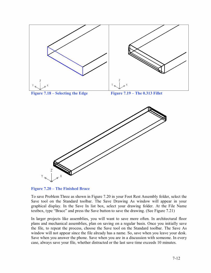
Figure 7.17 � Creating Part One and Moving the Part to the Origin To move part one to the drawing origin of 0,0,0 on the x, y and z axis, pick the Move tool on the Modify toolbar and select the 3D solid and Enter. At the prompt, �specify base point or displacement�, select the endpoint at the lower right hand side of the entity, which will become the part one�s insertion point into the assembly drawing. At the �second point of displacement�, type 0,0,0 and Enter. Select the Fillet tool on the Modify toolbar. Again, this is a very simple command, because moments after picking the tool, type an �R� for radius and then 0.313 for the measurement. Now pick the vertical line on the straight corner and Enter and the line will become dotted. At the prompt, �Select an edge or [Chain/Radius]:� pick the other three lines on the periphery as shown in blue in Figure 7.18. Enter and the rounded edges will appear as shown in Figure 7.19. Repeat the process for the other side of problem three and you will have symmetrical fillets on both ends.
7-12
Figure 7.18 � Selecting the Edge Figure 7.19 � The 0.313 Fillet
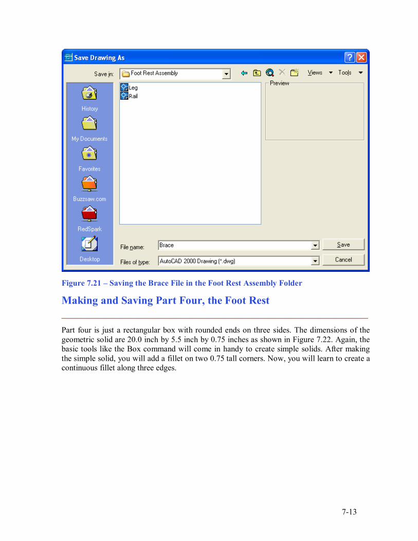
Figure 7.20 � The Finished Brace To save Problem Three as shown in Figure 7.20 in your Foot Rest Assembly folder, select the Save tool on the Standard toolbar. The Save Drawing As window will appear in your graphical display. In the Save In list box, select your drawing folder. At the File Name textbox, type �Brace� and press the Save button to save the drawing. (See Figure 7.21) In larger projects like assemblies, you will want to save more often. In architectural floor plans and mechanical assemblies, plan on saving on a regular basis. Once you initially save the file, to repeat the process, choose the Save tool on the Standard toolbar. The Save As window will not appear since the file already has a name. So, save when you leave your desk. Save when you answer the phone. Save when you are in a discussion with someone. In every case, always save your file, whether distracted or the last save time exceeds 10 minutes.
7-13
Figure 7.21 � Saving the Brace File in the Foot Rest Assembly Folder
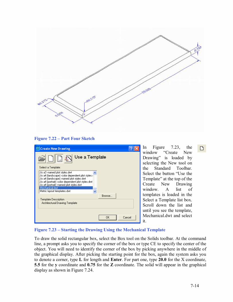
Making and Saving Part Four, the Foot Rest ________________________________________________________ Part four is just a rectangular box with rounded ends on three sides. The dimensions of the geometric solid are 20.0 inch by 5.5 inch by 0.75 inches as shown in Figure 7.22. Again, the basic tools like the Box command will come in handy to create simple solids. After making the simple solid, you will add a fillet on two 0.75 tall corners. Now, you will learn to create a continuous fillet along three edges.
7-14
Figure 7.22 � Part Four Sketch
In Figure 7.23, the window �Create New Drawing� is loaded by selecting the New tool on the Standard Toolbar. Select the button �Use the Template� at the top of the Create New Drawing window. A list of templates is loaded in the Select a Template list box. Scroll down the list and until you see the template, Mechanical.dwt and select it.
Figure 7.23 � Starting the Drawing Using the Mechanical Template To draw the solid rectangular box, select the Box tool on the Solids toolbar. At the command line, a prompt asks you to specify the corner of the box or type CE to specify the center of the object. You will need to identify the corner of the box by picking anywhere in the middle of the graphical display. After picking the starting point for the box, again the system asks you to denote a corner, type L for length and Enter. For part one, type 20.0 for the X coordinate, 5.5 for the y coordinate and 0.75 for the Z coordinate. The solid will appear in the graphical display as shown in Figure 7.24.
7-15
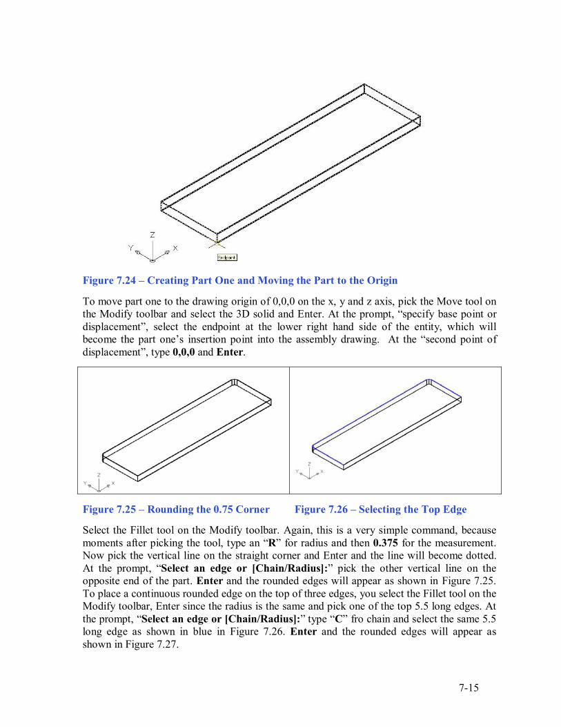
Figure 7.24 � Creating Part One and Moving the Part to the Origin To move part one to the drawing origin of 0,0,0 on the x, y and z axis, pick the Move tool on the Modify toolbar and select the 3D solid and Enter. At the prompt, �specify base point or displacement�, select the endpoint at the lower right hand side of the entity, which will become the part one�s insertion point into the assembly drawing. At the �second point of displacement�, type 0,0,0 and Enter.
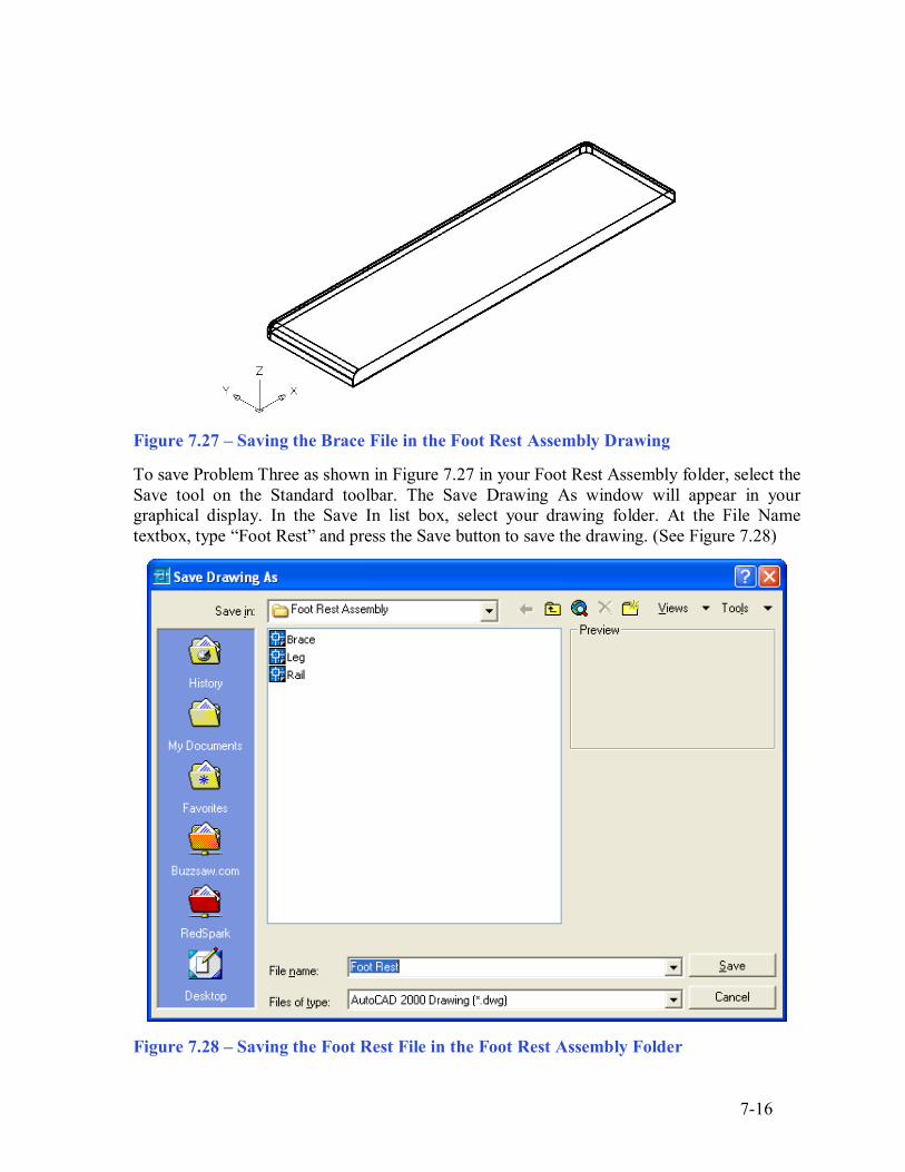
Figure 7.25 � Rounding the 0.75 Corner Figure 7.26 � Selecting the Top Edge Select the Fillet tool on the Modify toolbar. Again, this is a very simple command, because moments after picking the tool, type an �R� for radius and then 0.375 for the measurement. Now pick the vertical line on the straight corner and Enter and the line will become dotted. At the prompt, �Select an edge or [Chain/Radius]:� pick the other vertical line on the opposite end of the part. Enter and the rounded edges will appear as shown in Figure 7.25. To place a continuous rounded edge on the top of three edges, you select the Fillet tool on the Modify toolbar, Enter since the radius is the same and pick one of the top 5.5 long edges. At the prompt, �Select an edge or [Chain/Radius]:� type �C� fro chain and select the same 5.5 long edge as shown in blue in Figure 7.26. Enter and the rounded edges will appear as shown in Figure 7.27.
7-16
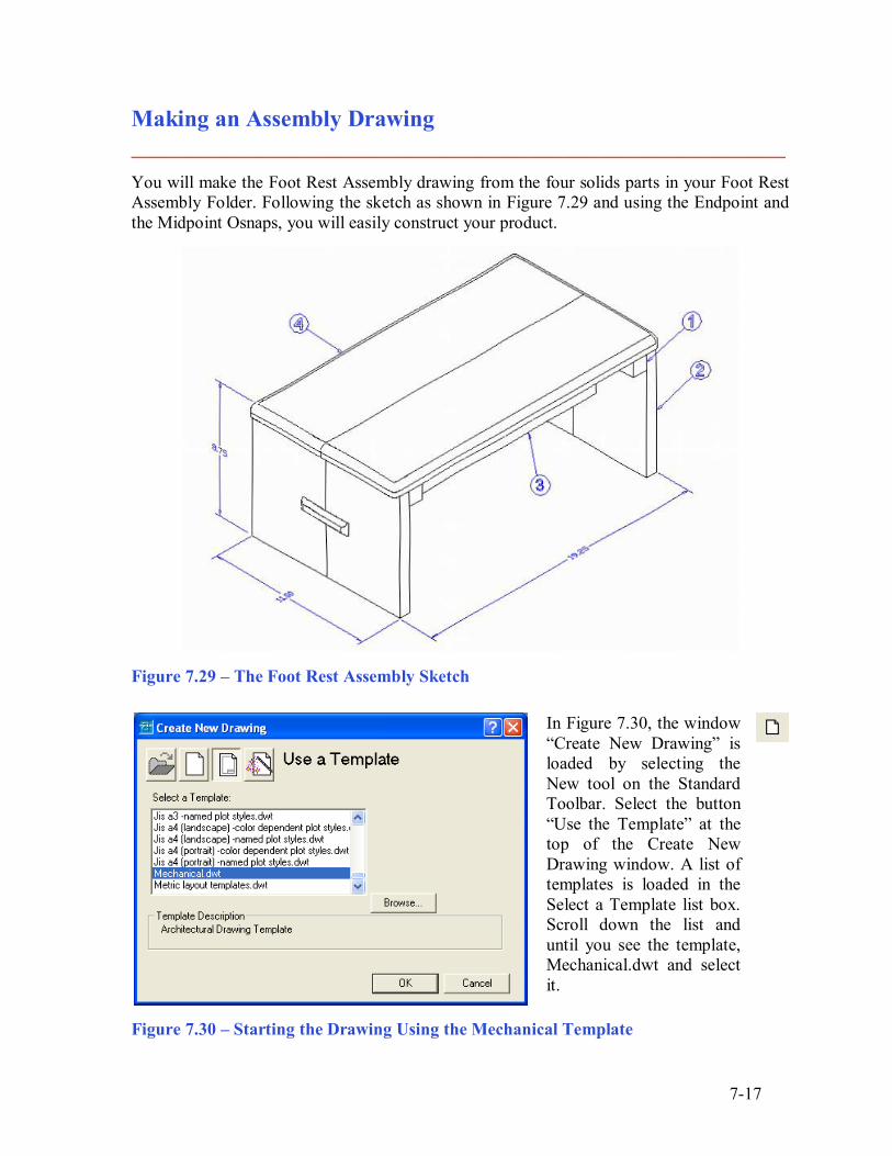
Figure 7.27 � Saving the Brace File in the Foot Rest Assembly Drawing To save Problem Three as shown in Figure 7.27 in your Foot Rest Assembly folder, select the Save tool on the Standard toolbar. The Save Drawing As window will appear in your graphical display. In the Save In list box, select your drawing folder. At the File Name textbox, type �Foot Rest� and press the Save button to save the drawing. (See Figure 7.28)
Figure 7.28 � Saving the Foot Rest File in the Foot Rest Assembly Folder
7-17
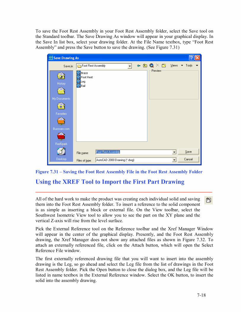
Making an Assembly Drawing ________________________________________________________ You will make the Foot Rest Assembly drawing from the four solids parts in your Foot Rest Assembly Folder. Following the sketch as shown in Figure 7.29 and using the Endpoint and the Midpoint Osnaps, you will easily construct your product.
Figure 7.29 � The Foot Rest Assembly Sketch
In Figure 7.30, the window �Create New Drawing� is loaded by selecting the New tool on the Standard Toolbar. Select the button �Use the Template� at the top of the Create New Drawing window. A list of templates is loaded in the Select a Template list box. Scroll down the list and until you see the template, Mechanical.dwt and select it.
Figure 7.30 � Starting the Drawing Using the Mechanical Template
7-18
To save the Foot Rest Assembly in your Foot Rest Assembly folder, select the Save tool on the Standard toolbar. The Save Drawing As window will appear in your graphical display. In the Save In list box, select your drawing folder. At the File Name textbox, type �Foot Rest Assembly� and press the Save button to save the drawing. (See Figure 7.31)
Figure 7.31 � Saving the Foot Rest Assembly File in the Foot Rest Assembly Folder
Using the XREF Tool to Import the First Part Drawing ________________________________________________________ All of the hard work to make the product was creating each individual solid and saving them into the Foot Rest Assembly folder. To insert a reference to the solid component is as simple as inserting a block or external file. On the View toolbar, select the Southwest Isometric View tool to allow you to see the part on the XY plane and the vertical Z-axis will rise from the level surface.
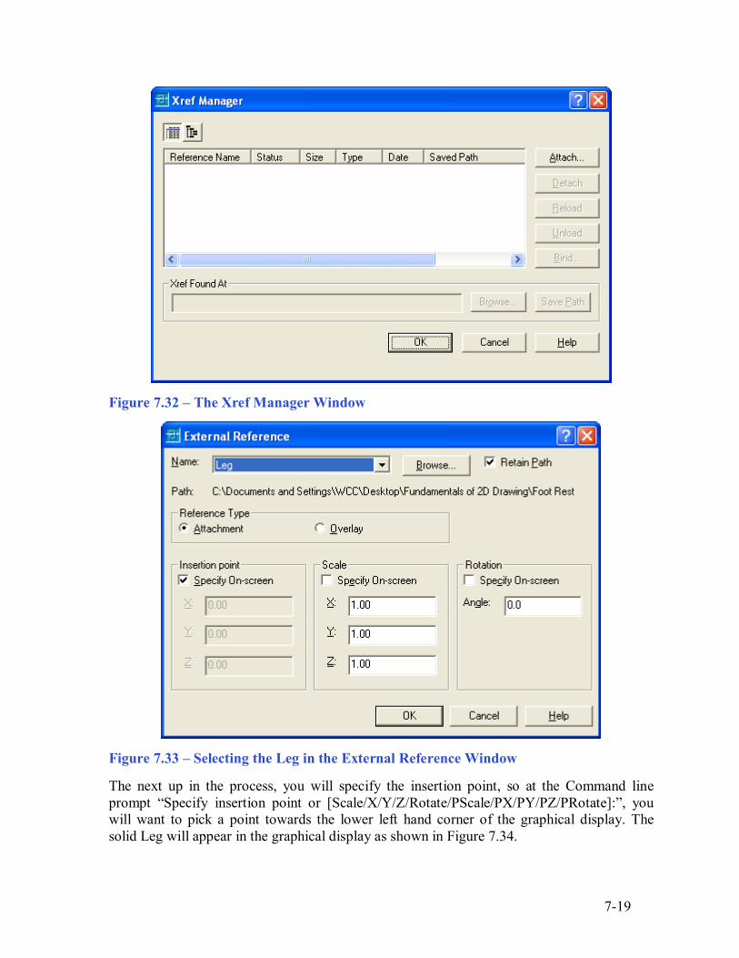
Pick the External Reference tool on the Reference toolbar and the Xref Manager Window will appear in the center of the graphical display. Presently, and the Foot Rest Assembly drawing, the Xref Manager does not show any attached files as shown in Figure 7.32. To attach an externally referenced file, click on the Attach button, which will open the Select Reference File window.
The first externally referenced drawing file that you will want to insert into the assembly drawing is the Leg, so go ahead and select the Leg file from the list of drawings in the Foot Rest Assembly folder. Pick the Open button to close the dialog box, and the Leg file will be listed in name textbox in the External Reference window. Select the OK button, to insert the solid into the assembly drawing.
7-19
Figure 7.32 � The Xref Manager Window
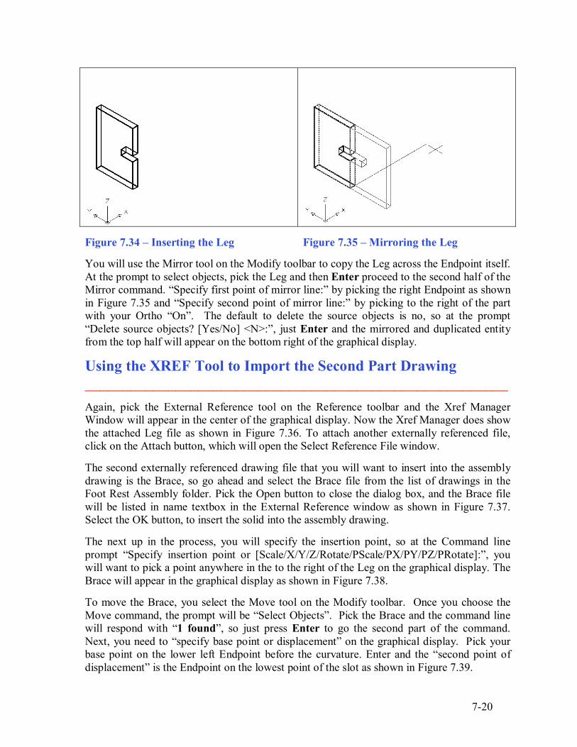
Figure 7.33 � Selecting the Leg in the External Reference Window The next up in the process, you will specify the insertion point, so at the Command line prompt �Specify insertion point or [Scale/X/Y/Z/Rotate/PScale/PX/PY/PZ/PRotate]:�, you will want to pick a point towards the lower left hand corner of the graphical display. The solid Leg will appear in the graphical display as shown in Figure 7.34.
7-20
Figure 7.34 � Inserting the Leg Figure 7.35 � Mirroring the Leg You will use the Mirror tool on the Modify toolbar to copy the Leg across the Endpoint itself. At the prompt to select objects, pick the Leg and then Enter proceed to the second half of the Mirror command. �Specify first point of mirror line:� by picking the right Endpoint as shown in Figure 7.35 and �Specify second point of mirror line:� by picking to the right of the part with your Ortho �On�. The default to delete the source objects is no, so at the prompt �Delete source objects? [Yes/No] <N>:�, just Enter and the mirrored and duplicated entity from the top half will appear on the bottom right of the graphical display.
Using the XREF Tool to Import the Second Part Drawing ________________________________________________________ Again, pick the External Reference tool on the Reference toolbar and the Xref Manager Window will appear in the center of the graphical display. Now the Xref Manager does show the attached Leg file as shown in Figure 7.36. To attach another externally referenced file, click on the Attach button, which will open the Select Reference File window. The second externally referenced drawing file that you will want to insert into the assembly drawing is the Brace, so go ahead and select the Brace file from the list of drawings in the Foot Rest Assembly folder. Pick the Open button to close the dialog box, and the Brace file will be listed in name textbox in the External Reference window as shown in Figure 7.37. Select the OK button, to insert the solid into the assembly drawing. The next up in the process, you will specify the insertion point, so at the Command line prompt �Specify insertion point or [Scale/X/Y/Z/Rotate/PScale/PX/PY/PZ/PRotate]:�, you will want to pick a point anywhere in the to the right of the Leg on the graphical display. The Brace will appear in the graphical display as shown in Figure 7.38. To move the Brace, you select the Move tool on the Modify toolbar. Once you choose the Move command, the prompt will be �Select Objects�. Pick the Brace and the command line will respond with �1 found�, so just press Enter to go the second part of the command. Next, you need to �specify base point or displacement� on the graphical display. Pick your base point on the lower left Endpoint before the curvature. Enter and the �second point of displacement� is the Endpoint on the lowest point of the slot as shown in Figure 7.39.
7-21
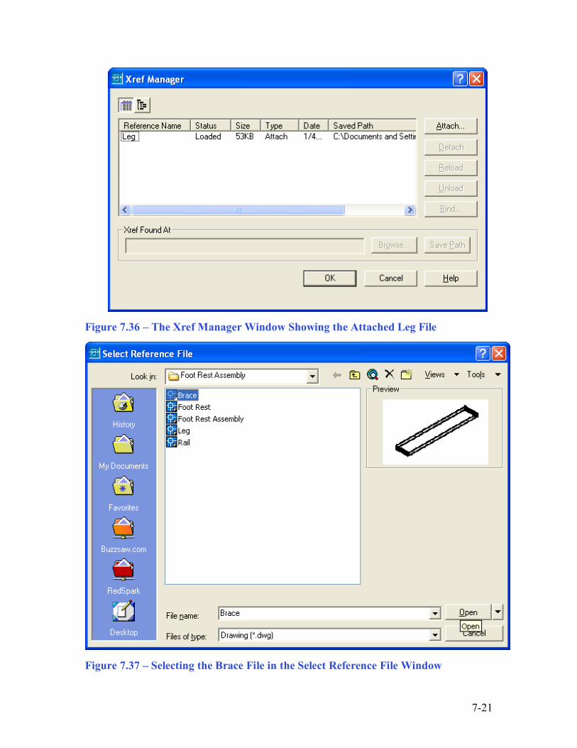
Figure 7.36 � The Xref Manager Window Showing the Attached Leg File
Figure 7.37 � Selecting the Brace File in the Select Reference File Window
7-22
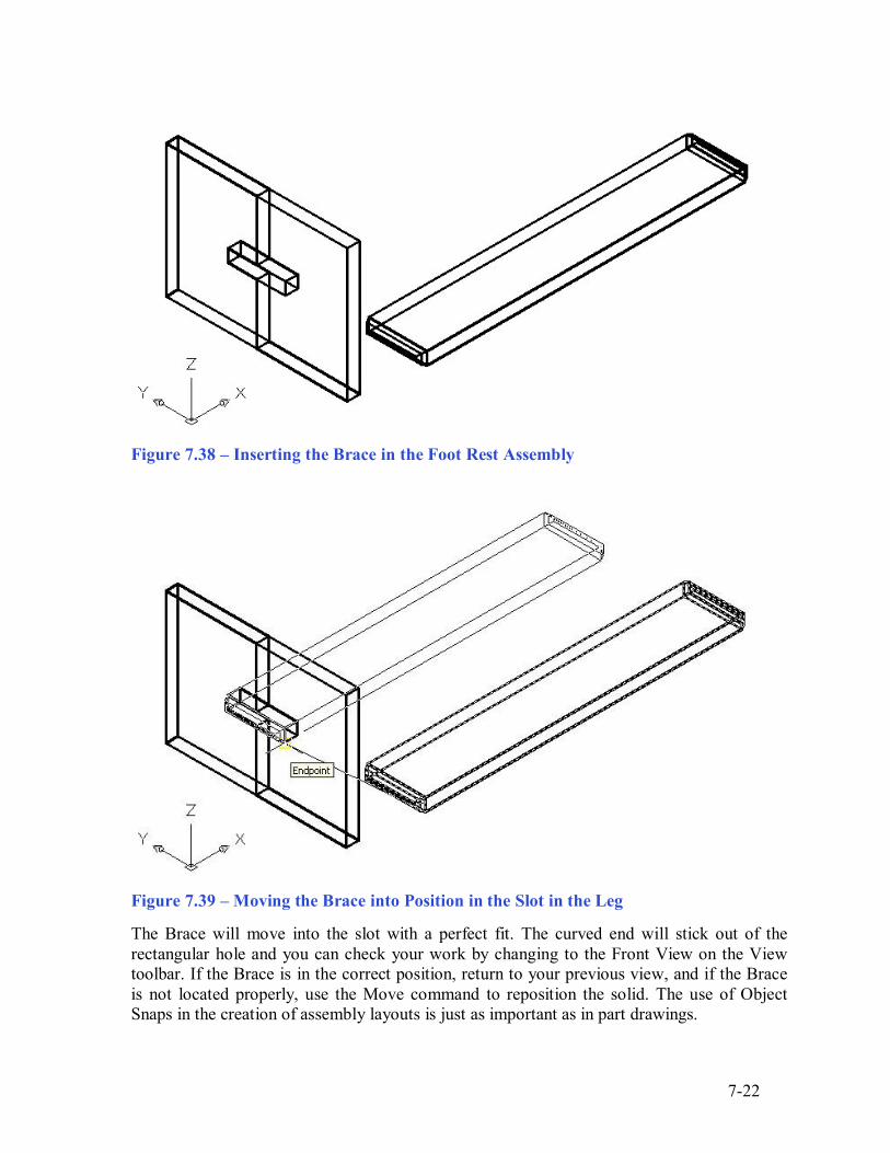
Figure 7.38 � Inserting the Brace in the Foot Rest Assembly
Figure 7.39 � Moving the Brace into Position in the Slot in the Leg The Brace will move into the slot with a perfect fit. The curved end will stick out of the rectangular hole and you can check your work by changing to the Front View on the View toolbar. If the Brace is in the correct position, return to your previous view, and if the Brace is not located properly, use the Move command to reposition the solid. The use of Object Snaps in the creation of assembly layouts is just as important as in part drawings.
7-23
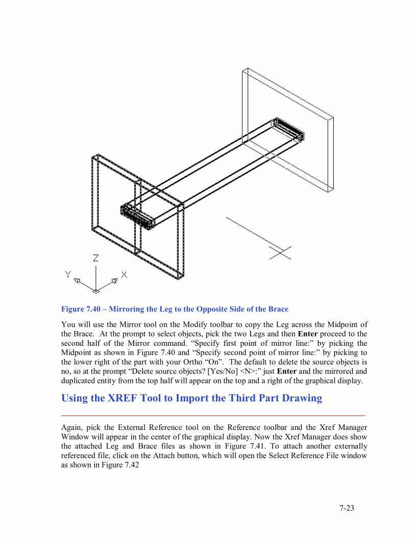
Figure 7.40 � Mirroring the Leg to the Opposite Side of the Brace You will use the Mirror tool on the Modify toolbar to copy the Leg across the Midpoint of the Brace. At the prompt to select objects, pick the two Legs and then Enter proceed to the second half of the Mirror command. �Specify first point of mirror line:� by picking the Midpoint as shown in Figure 7.40 and �Specify second point of mirror line:� by picking to the lower right of the part with your Ortho �On�. The default to delete the source objects is no, so at the prompt �Delete source objects? [Yes/No] <N>:� just Enter and the mirrored and duplicated entity from the top half will appear on the top and a right of the graphical display.
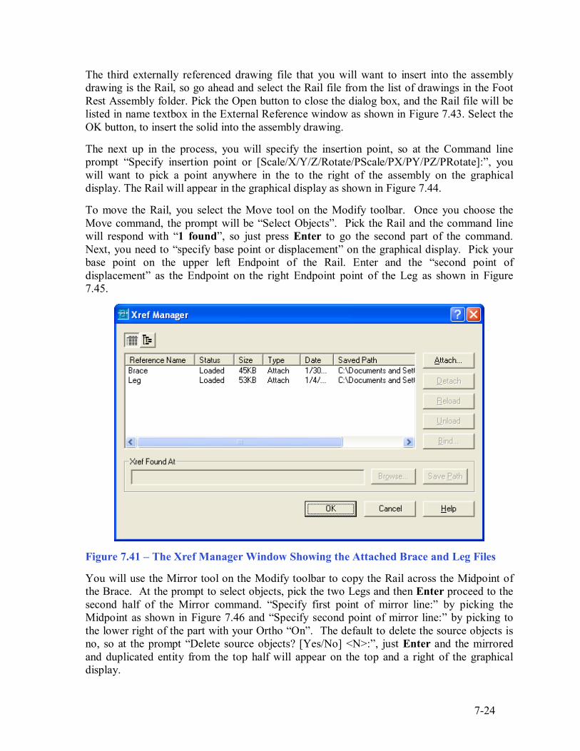
Using the XREF Tool to Import the Third Part Drawing ________________________________________________________ Again, pick the External Reference tool on the Reference toolbar and the Xref Manager Window will appear in the center of the graphical display. Now the Xref Manager does show the attached Leg and Brace files as shown in Figure 7.41. To attach another externally referenced file, click on the Attach button, which will open the Select Reference File window as shown in Figure 7.42
7-24
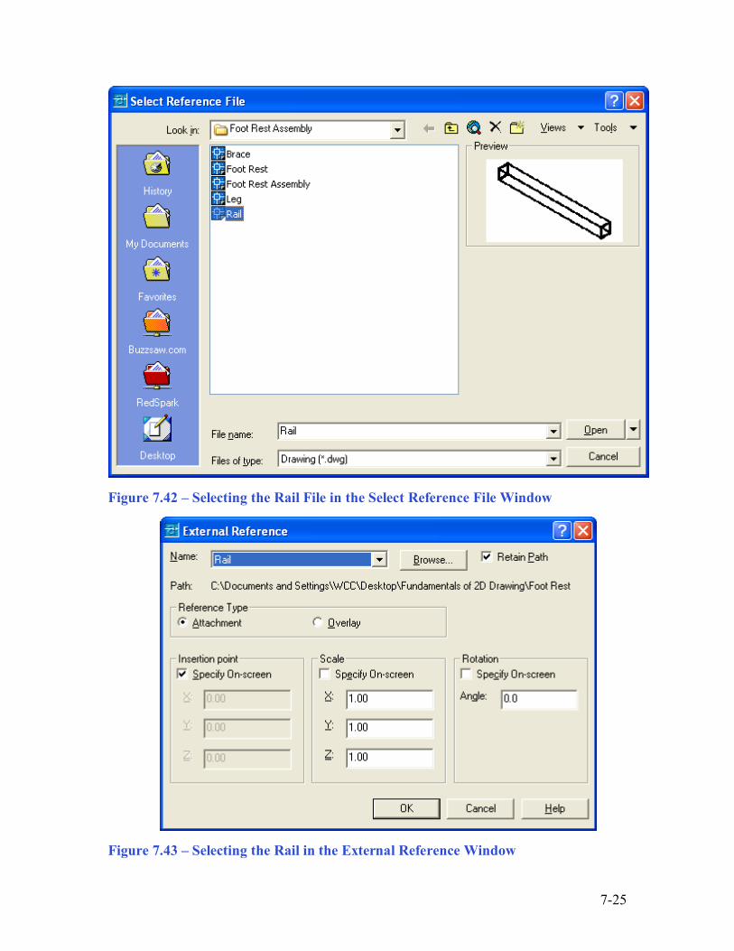
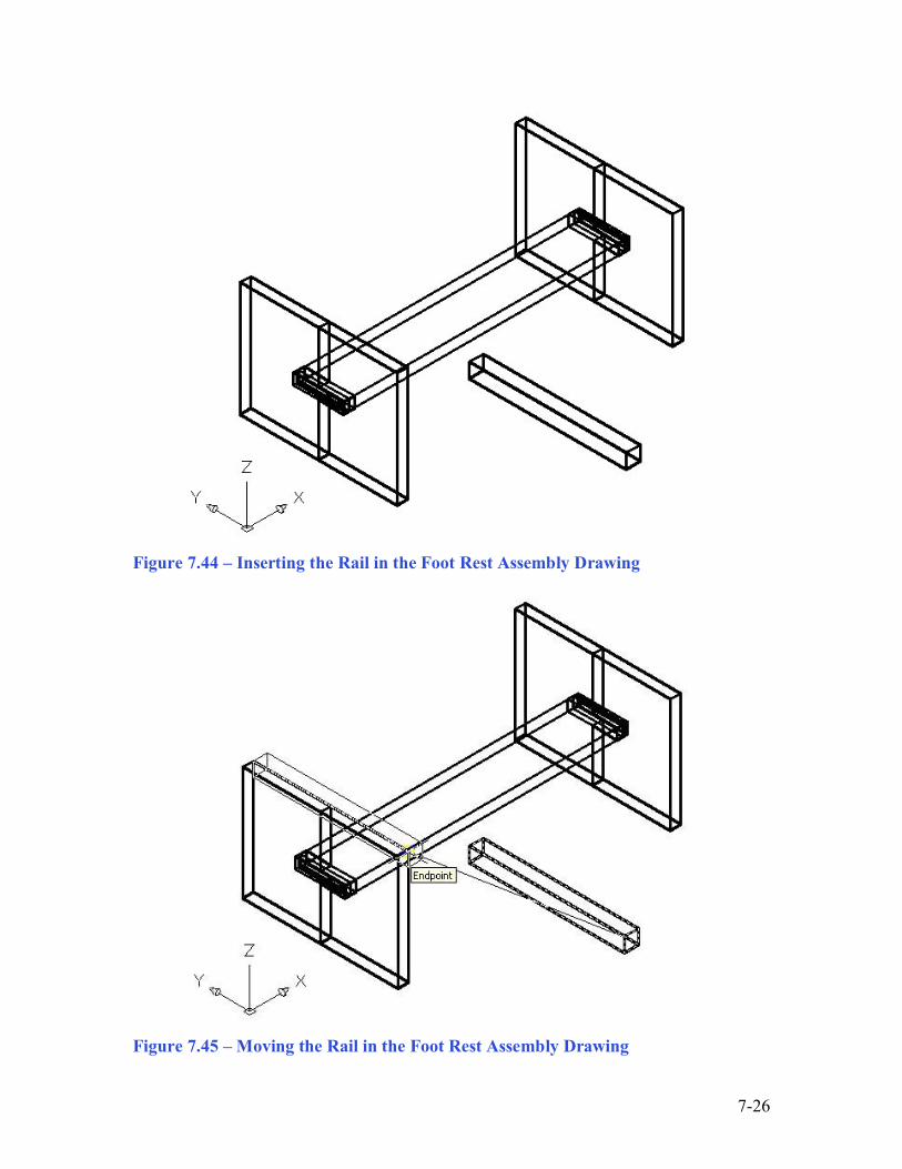
The third externally referenced drawing file that you will want to insert into the assembly drawing is the Rail, so go ahead and select the Rail file from the list of drawings in the Foot Rest Assembly folder. Pick the Open button to close the dialog box, and the Rail file will be listed in name textbox in the External Reference window as shown in Figure 7.43. Select the OK button, to insert the solid into the assembly drawing. The next up in the process, you will specify the insertion point, so at the Command line prompt �Specify insertion point or [Scale/X/Y/Z/Rotate/PScale/PX/PY/PZ/PRotate]:�, you will want to pick a point anywhere in the to the right of the assembly on the graphical display. The Rail will appear in the graphical display as shown in Figure 7.44. To move the Rail, you select the Move tool on the Modify toolbar. Once you choose the Move command, the prompt will be �Select Objects�. Pick the Rail and the command line will respond with �1 found�, so just press Enter to go the second part of the command. Next, you need to �specify base point or displacement� on the graphical display. Pick your base point on the upper left Endpoint of the Rail. Enter and the �second point of displacement� as the Endpoint on the right Endpoint point of the Leg as shown in Figure 7.45.
Figure 7.41 � The Xref Manager Window Showing the Attached Brace and Leg Files You will use the Mirror tool on the Modify toolbar to copy the Rail across the Midpoint of the Brace. At the prompt to select objects, pick the two Legs and then Enter proceed to the second half of the Mirror command. �Specify first point of mirror line:� by picking the Midpoint as shown in Figure 7.46 and �Specify second point of mirror line:� by picking to the lower right of the part with your Ortho �On�. The default to delete the source objects is no, so at the prompt �Delete source objects? [Yes/No] <N>:�, just Enter and the mirrored and duplicated entity from the top half will appear on the top and a right of the graphical display.
7-25
Figure 7.42 � Selecting the Rail File in the Select Reference File Window
Figure 7.43 � Selecting the Rail in the External Reference Window
7-26
Figure 7.44 � Inserting the Rail in the Foot Rest Assembly Drawing
Figure 7.45 � Moving the Rail in the Foot Rest Assembly Drawing
7-27
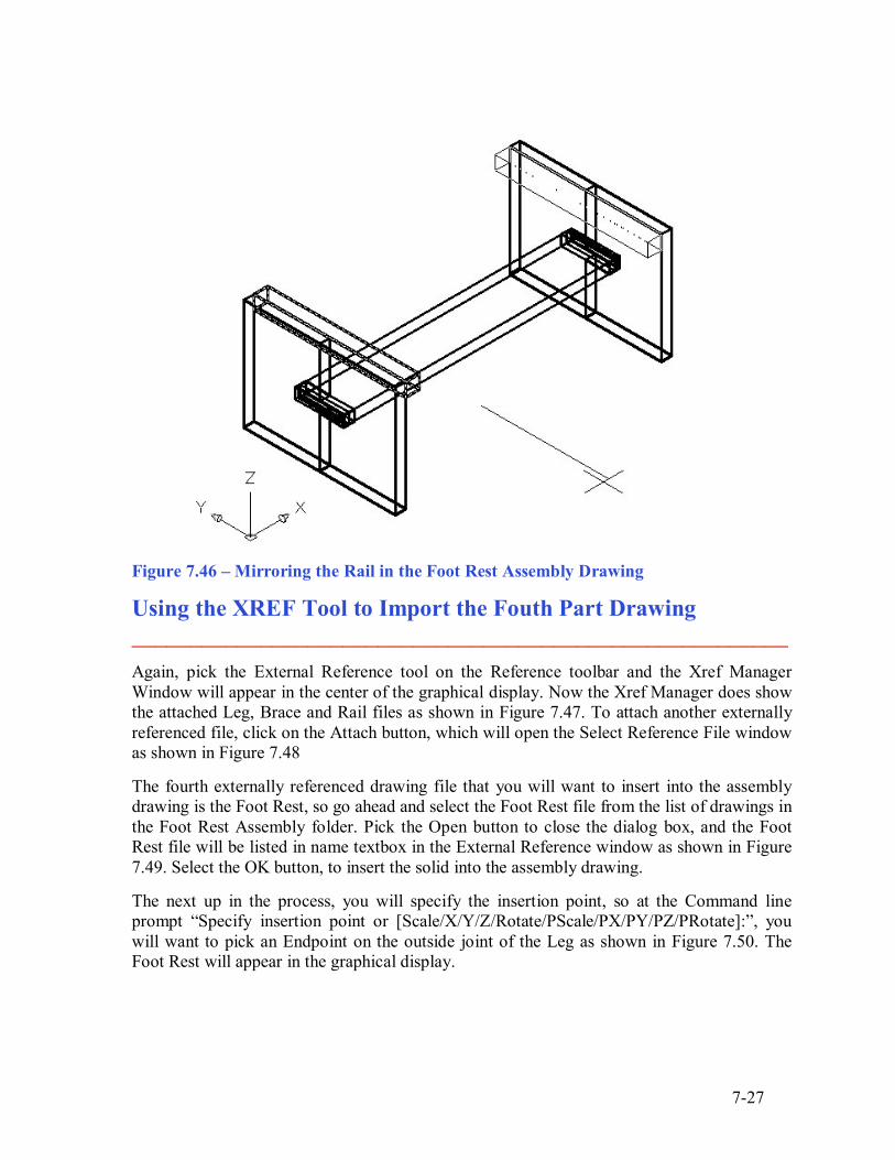
Figure 7.46 � Mirroring the Rail in the Foot Rest Assembly Drawing
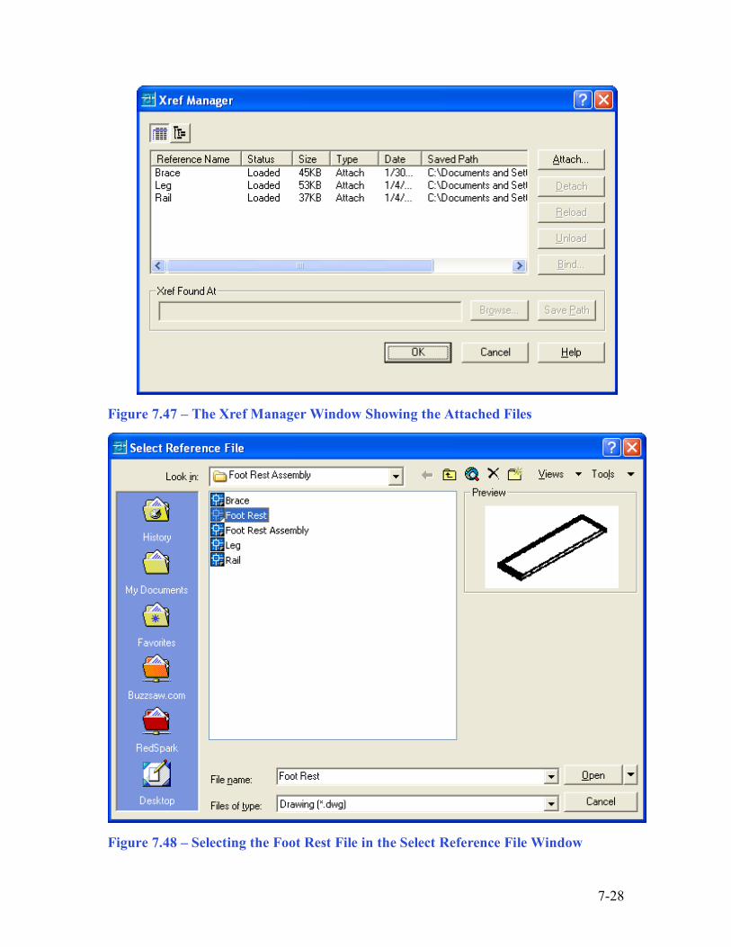
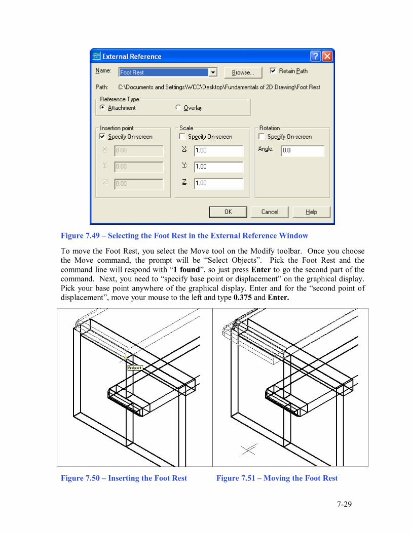
Using the XREF Tool to Import the Fouth Part Drawing ________________________________________________________ Again, pick the External Reference tool on the Reference toolbar and the Xref Manager Window will appear in the center of the graphical display. Now the Xref Manager does show the attached Leg, Brace and Rail files as shown in Figure 7.47. To attach another externally referenced file, click on the Attach button, which will open the Select Reference File window as shown in Figure 7.48 The fourth externally referenced drawing file that you will want to insert into the assembly drawing is the Foot Rest, so go ahead and select the Foot Rest file from the list of drawings in the Foot Rest Assembly folder. Pick the Open button to close the dialog box, and the Foot Rest file will be listed in name textbox in the External Reference window as shown in Figure 7.49. Select the OK button, to insert the solid into the assembly drawing. The next up in the process, you will specify the insertion point, so at the Command line prompt �Specify insertion point or [Scale/X/Y/Z/Rotate/PScale/PX/PY/PZ/PRotate]:�, you will want to pick an Endpoint on the outside joint of the Leg as shown in Figure 7.50. The Foot Rest will appear in the graphical display.
7-28
Figure 7.47 � The Xref Manager Window Showing the Attached Files
Figure 7.48 � Selecting the Foot Rest File in the Select Reference File Window
7-29
Figure 7.49 � Selecting the Foot Rest in the External Reference Window To move the Foot Rest, you select the Move tool on the Modify toolbar. Once you choose the Move command, the prompt will be �Select Objects�. Pick the Foot Rest and the command line will respond with �1 found�, so just press Enter to go the second part of the command. Next, you need to �specify base point or displacement� on the graphical display. Pick your base point anywhere of the graphical display. Enter and for the �second point of displacement�, move your mouse to the left and type 0.375 and Enter.
Figure 7.50 � Inserting the Foot Rest Figure 7.51 � Moving the Foot Rest

7-30
Figure 7.52 � Using the Hide Command to View the Assembly You will use the Mirror tool on the Modify toolbar to copy the Foot Rest across the Endpoint of Leg joint. At the prompt to select objects, pick the Foot Rest and then Enter proceed to the second half of the Mirror command. �Specify first point of mirror line:� by picking the Endpoint as shown in Figure 7.53 and �Specify second point of mirror line:� by picking to the lower left of the part with your Ortho �On�. The default to delete the source objects is no, so at the prompt �Delete source objects? [Yes/No] <N>:�, just Enter and the mirrored entity from the top half will appear on the bottom and a right of the graphical display.
Figure 7.52 � Mirroring the Foot Rest in the Foot Rest Assembly Drawing
7-31
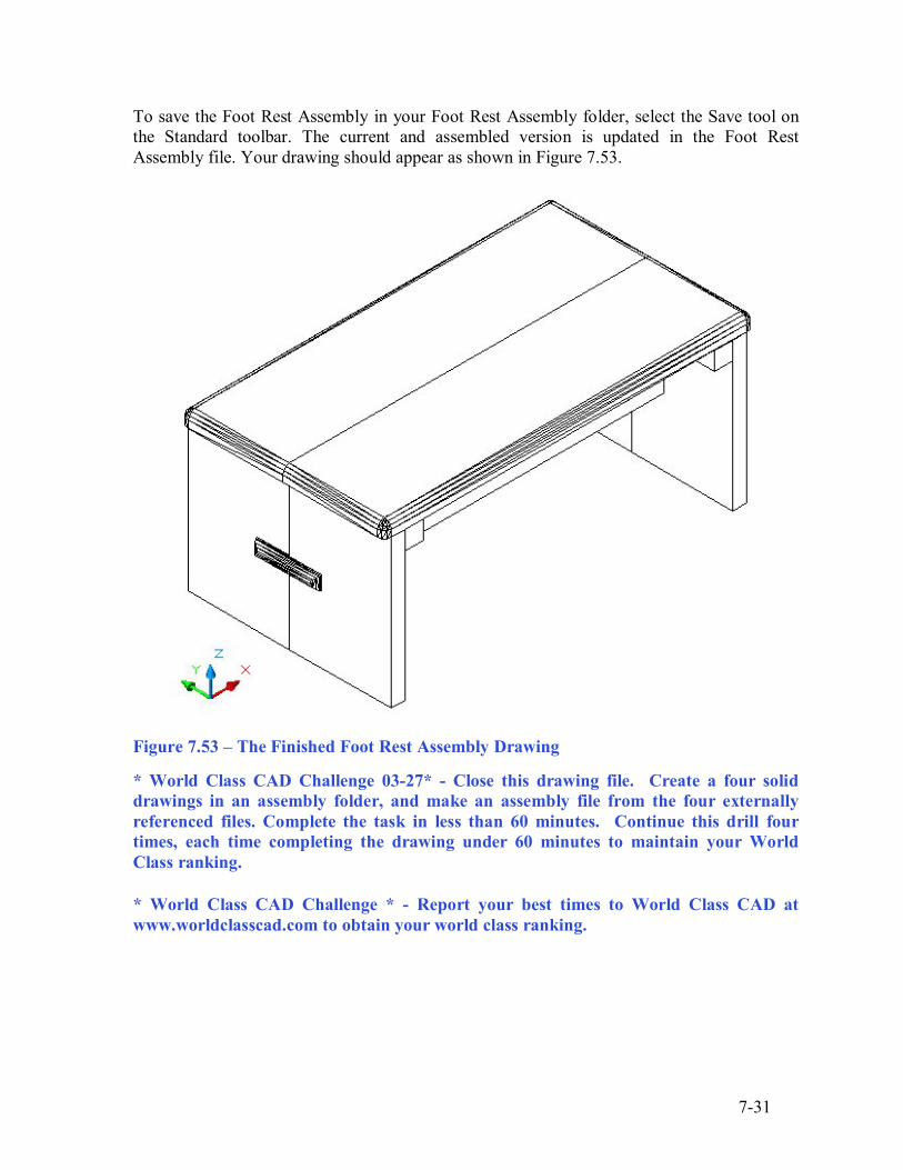
To save the Foot Rest Assembly in your Foot Rest Assembly folder, select the Save tool on the Standard toolbar. The current and assembled version is updated in the Foot Rest Assembly file. Your drawing should appear as shown in Figure 7.53.
Figure 7.53 � The Finished Foot Rest Assembly Drawing
* World Class CAD Challenge 03-27* - Close this drawing file. Create a four solid drawings in an assembly folder, and make an assembly file from the four externally referenced files. Complete the task in less than 60 minutes. Continue this drill four times, each time completing the drawing under 60 minutes to maintain your World Class ranking.
* World Class CAD Challenge * - Report your best times to World Class CAD at www.worldclasscad.com to obtain your world class ranking.