Embed Size (px)
Citation preview
Creating a Humidor Control Box alearn.sparkfun.com tutorial
Available online at: http://sfe.io/t42
Contents
Overview3D Design3D AssemblyCreating Tool PathsTime to CutResources and Going Further
Overview
In this tutorial, I am going to go through the process of how the SparkFun humidor was designedand built. A humidor is any kind of box or room with constant humidity, used to store cigars,cigarettes, pipe tobacco, or in this case sensors. I’ll be covering designing a 3D software model andfabricating it using a CNC router.
Page 1 of 31
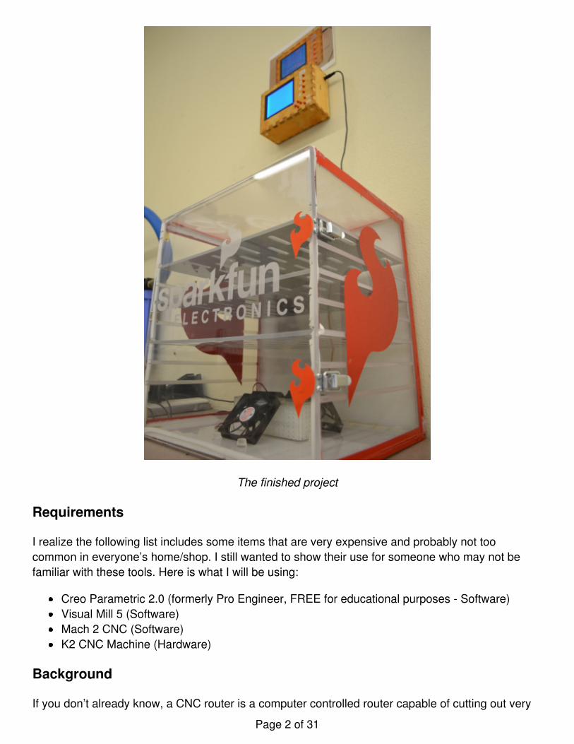
The finished project
Requirements
I realize the following list includes some items that are very expensive and probably not toocommon in everyone’s home/shop. I still wanted to show their use for someone who may not befamiliar with these tools. Here is what I will be using:
Creo Parametric 2.0 (formerly Pro Engineer, FREE for educational purposes - Software)Visual Mill 5 (Software)Mach 2 CNC (Software)K2 CNC Machine (Hardware)
Background
If you don’t already know, a CNC router is a computer controlled router capable of cutting out very
Page 2 of 31
complex shapes. CNC stands for Computer Numerical Control. The CNC machine is connected to acomputer and is given very precise three dimensional coordinates to which the machine shouldmove. Using a combination of motors and encoders, the machine is able to cut out nearly anythingyou can draw. There is lots to cover, so lets get started.
3D Design
Our Production department came to me needing a humidor built. They needed a better system tore-humidify a select few of our boards that need it after coming out of the reflow oven.
I am a very visual person. I like to see exactly what I have designed and how it fits together before Istart making it. By doing this, it is easy to see where my mistakes are and correct them.
For this project, I designed both the humidor and the control box for it. The control box allows ourProduction team to select which board they are placing in the humidor, iit will keep track of the timeit has been in there. It also makes sure the humidity stays at the required percentage. I’m not goingto cover much of the humidor in this tutorial, however. I laser cut acrylic and epoxied it together inthe shape of a box. When it was dry, I added some weather strip to the front door to seal it and putcaulk in all the joints to ensure it was air tight. Not too much going on there!
The control box was really fun to make. I decided to cut ‘teeth’ in all of the edges so it would fittogether like a 3D puzzle. Here at Sparkfun, we use Creo Parametric 2.0 for our 3D modeling. OurArduino and breadboard holder was designed with this along with all of our retail clamshellpackaging. I learned this program in High School, and of all the modeling software I have usedalong the way, it is my favorite. Before I begin, I want to tell you that this tutorial only scratches thesurface of the feature in Creo. I’m only going to cover a few main points and features, there iscertainly more than one way to do all of this. Let’s start designing!
(1) In the picture below, we are going to start drawing the top panel for the control box. The areawith the labels ‘FRONT’, ‘TOP’, and ‘RIGHT’ is our workspace. We want to choose one thataccurately describes the surface that we want to draw. Since this panel will go on the top side ofthe box, I am going to select the ‘TOP’ plane. Probably the most used feature is the Extrudecommand. This allows us to create material (or remove it) in the shape we want. So to recap, wechoose the ‘TOP’ plane and click Extrude.
Page 3 of 31
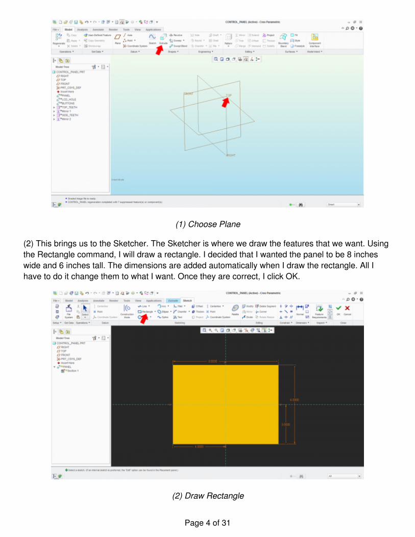
(1) Choose Plane
(2) This brings us to the Sketcher. The Sketcher is where we draw the features that we want. Usingthe Rectangle command, I will draw a rectangle. I decided that I wanted the panel to be 8 incheswide and 6 inches tall. The dimensions are added automatically when I draw the rectangle. All Ihave to do it change them to what I want. Once they are correct, I click OK.
(2) Draw Rectangle
Page 4 of 31
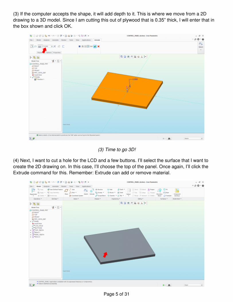
(3) If the computer accepts the shape, it will add depth to it. This is where we move from a 2Ddrawing to a 3D model. Since I am cutting this out of plywood that is 0.35” thick, I will enter that inthe box shown and click OK.
(3) Time to go 3D!
(4) Next, I want to cut a hole for the LCD and a few buttons. I’ll select the surface that I want tocreate the 2D drawing on. In this case, I’ll choose the top of the panel. Once again, I’ll click theExtrude command for this. Remember: Extrude can add or remove material.
Page 5 of 31
(4) Select the surface to cut through
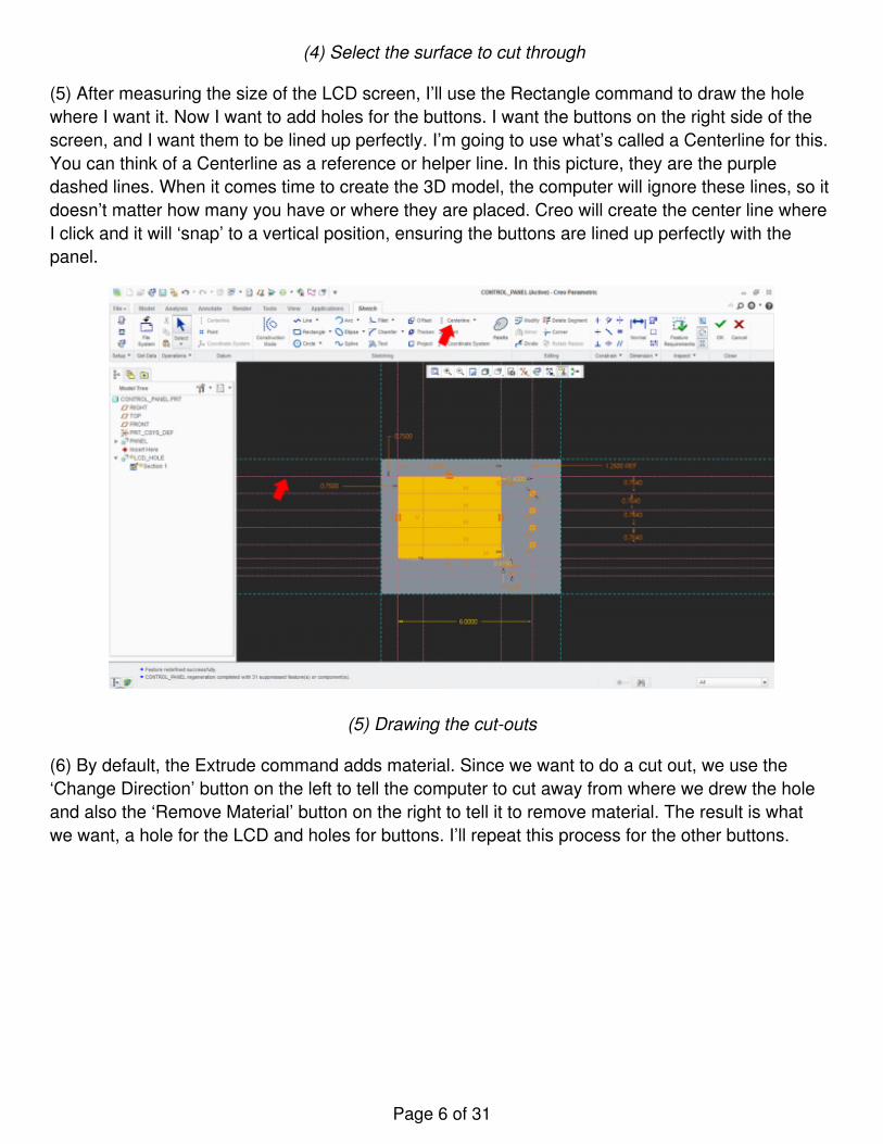
(5) After measuring the size of the LCD screen, I’ll use the Rectangle command to draw the holewhere I want it. Now I want to add holes for the buttons. I want the buttons on the right side of thescreen, and I want them to be lined up perfectly. I’m going to use what’s called a Centerline for this.You can think of a Centerline as a reference or helper line. In this picture, they are the purpledashed lines. When it comes time to create the 3D model, the computer will ignore these lines, so itdoesn’t matter how many you have or where they are placed. Creo will create the center line whereI click and it will ‘snap’ to a vertical position, ensuring the buttons are lined up perfectly with thepanel.
(5) Drawing the cut-outs
(6) By default, the Extrude command adds material. Since we want to do a cut out, we use the‘Change Direction’ button on the left to tell the computer to cut away from where we drew the holeand also the ‘Remove Material’ button on the right to tell it to remove material. The result is whatwe want, a hole for the LCD and holes for buttons. I’ll repeat this process for the other buttons.
Page 6 of 31
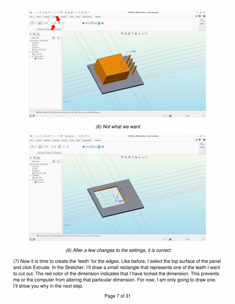
(6) Not what we want
(6) After a few changes to the settings, it is correct
(7) Now it is time to create the ‘teeth’ for the edges. Like before, I select the top surface of the paneland click Extrude. In the Sketcher, I’ll draw a small rectangle that represents one of the teeth I wantto cut out. The red color of the dimension indicates that I have locked the dimension. This preventsme or the computer from altering that particular dimension. For now, I am only going to draw one.I’ll show you why in the next step.
Page 7 of 31
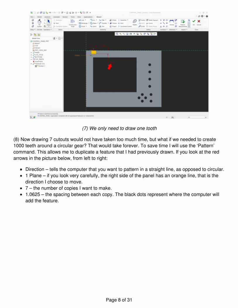
(7) We only need to draw one tooth
(8) Now drawing 7 cutouts would not have taken too much time, but what if we needed to create1000 teeth around a circular gear? That would take forever. To save time I will use the ‘Pattern’command. This allows me to duplicate a feature that I had previously drawn. If you look at the redarrows in the picture below, from left to right:
Direction – tells the computer that you want to pattern in a straight line, as opposed to circular.1 Plane – if you look very carefully, the right side of the panel has an orange line, that is thedirection I choose to move.7 – the number of copies I want to make.1.0625 – the spacing between each copy. The black dots represent where the computer willadd the feature.
Page 8 of 31
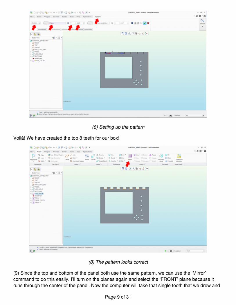
(8) Setting up the pattern
Voilà! We have created the top 8 teeth for our box!
(8) The pattern looks correct
(9) Since the top and bottom of the panel both use the same pattern, we can use the ‘Mirror’command to do this easily. I’ll turn on the planes again and select the ‘FRONT’ plane because itruns through the center of the panel. Now the computer will take that single tooth that we drew and
Page 9 of 31
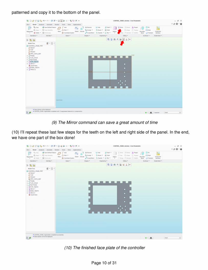
patterned and copy it to the bottom of the panel.
(9) The Mirror command can save a great amount of time
(10) I’ll repeat these last few steps for the teeth on the left and right side of the panel. In the end,we have one part of the box done!
(10) The finished face plate of the controller
Page 10 of 31
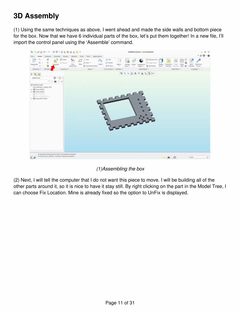
3D Assembly
(1) Using the same techniques as above, I went ahead and made the side walls and bottom piecefor the box. Now that we have 6 individual parts of the box, let’s put them together! In a new file, I’llimport the control panel using the ‘Assemble’ command.
(1)Assembling the box
(2) Next, I will tell the computer that I do not want this piece to move. I will be building all of theother parts around it, so it is nice to have it stay still. By right clicking on the part in the Model Tree, Ican choose Fix Location. Mine is already fixed so the option to UnFix is displayed.
Page 11 of 31
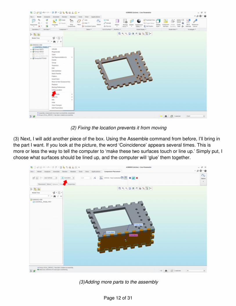
(2) Fixing the location prevents it from moving
(3) Next, I will add another piece of the box. Using the Assemble command from before, I’ll bring inthe part I want. If you look at the picture, the word ‘Coincidence’ appears several times. This ismore or less the way to tell the computer to ‘make these two surfaces touch or line up.’ Simply put, Ichoose what surfaces should be lined up, and the computer will ‘glue’ them together.
(3)Adding more parts to the assembly
Page 12 of 31
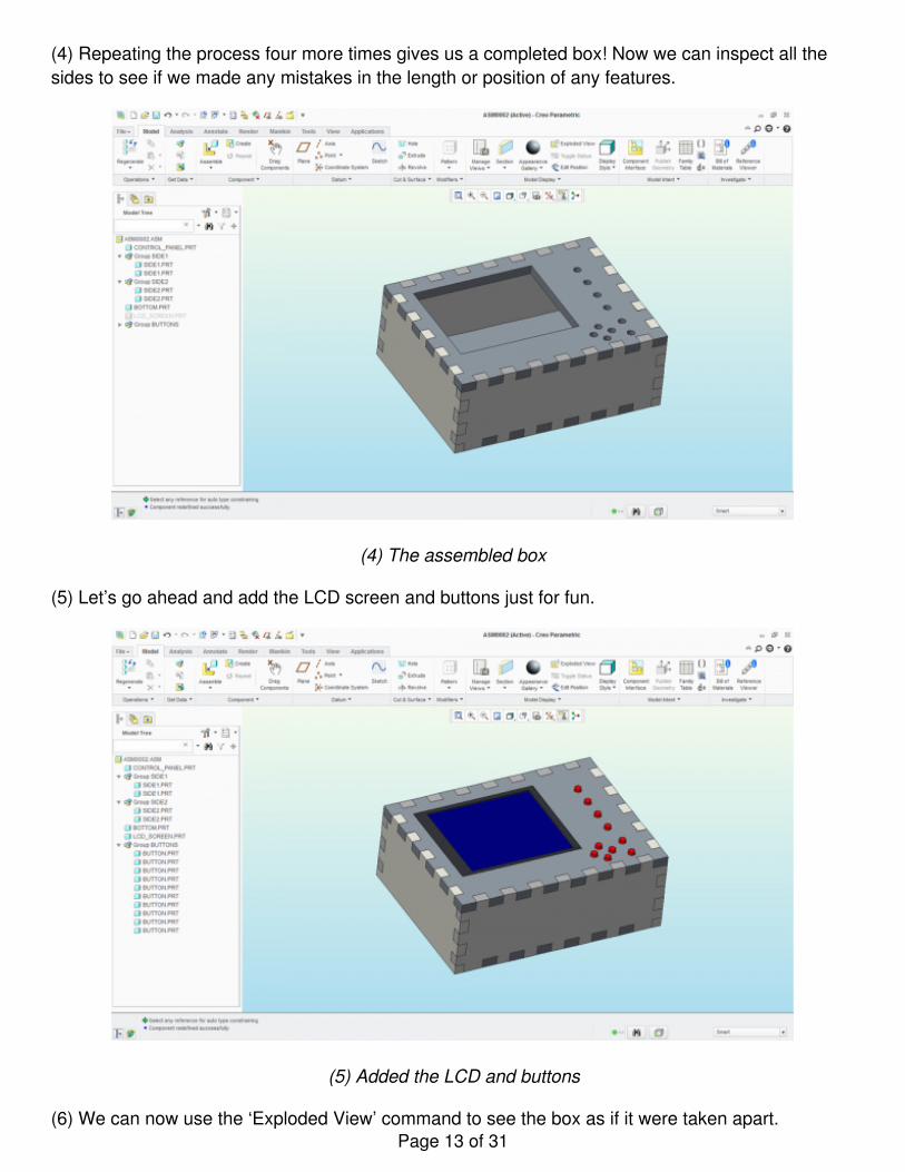
(4) Repeating the process four more times gives us a completed box! Now we can inspect all thesides to see if we made any mistakes in the length or position of any features.
(4) The assembled box
(5) Let’s go ahead and add the LCD screen and buttons just for fun.
(5) Added the LCD and buttons
(6) We can now use the ‘Exploded View’ command to see the box as if it were taken apart.Page 13 of 31
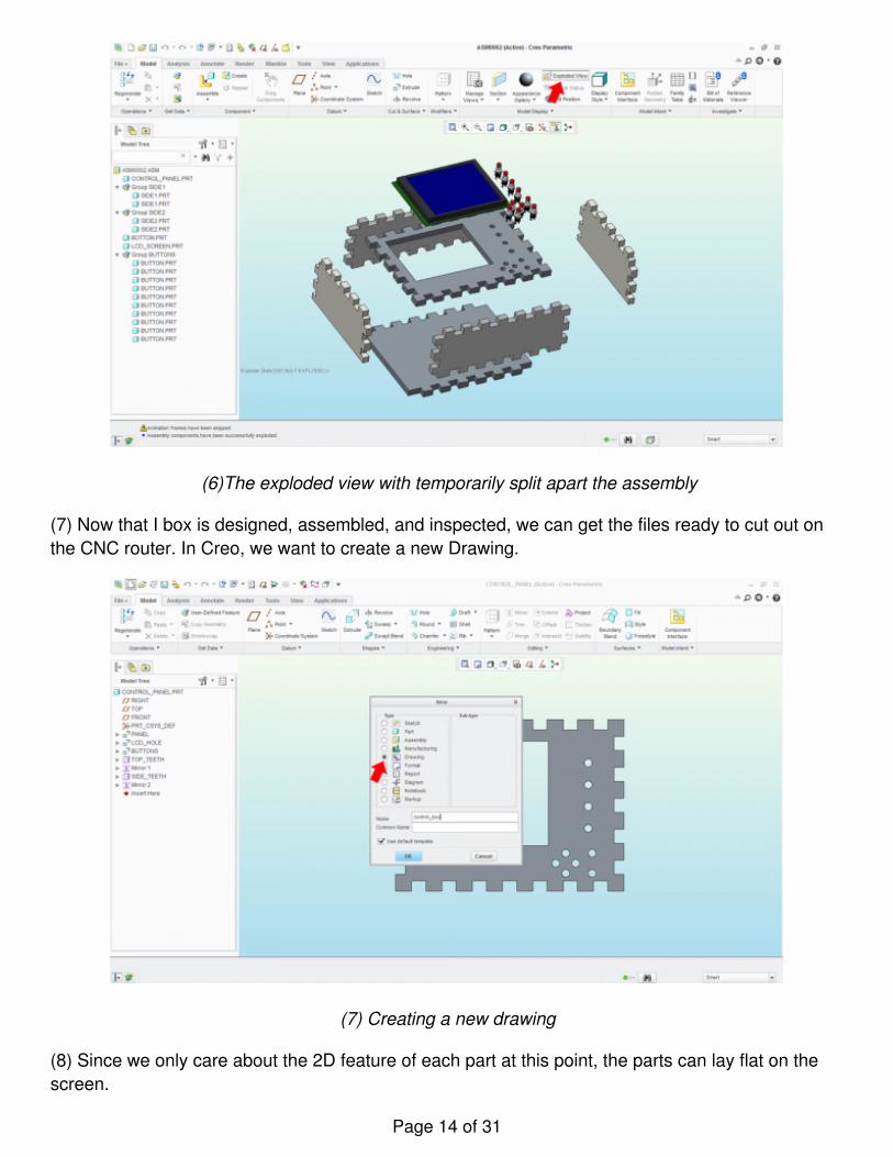
(6)The exploded view with temporarily split apart the assembly
(7) Now that I box is designed, assembled, and inspected, we can get the files ready to cut out onthe CNC router. In Creo, we want to create a new Drawing.
(7) Creating a new drawing
(8) Since we only care about the 2D feature of each part at this point, the parts can lay flat on thescreen.
Page 14 of 31
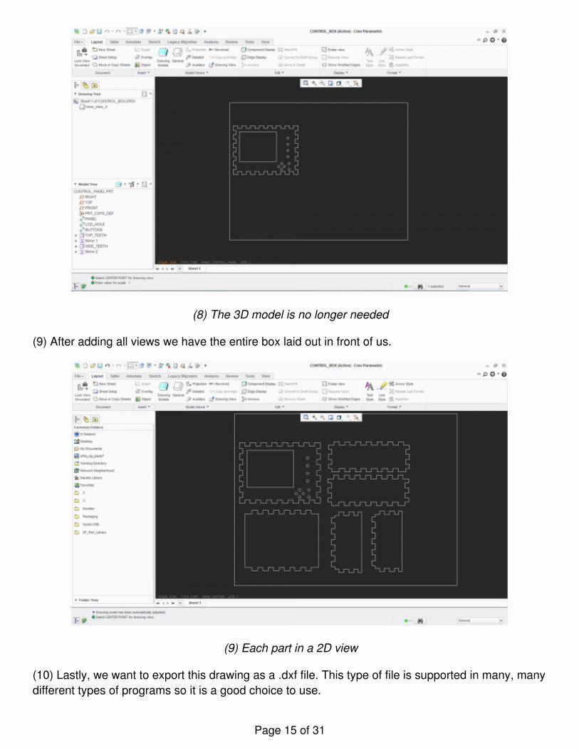
(8) The 3D model is no longer needed
(9) After adding all views we have the entire box laid out in front of us.
(9) Each part in a 2D view
(10) Lastly, we want to export this drawing as a .dxf file. This type of file is supported in many, manydifferent types of programs so it is a good choice to use.
Page 15 of 31
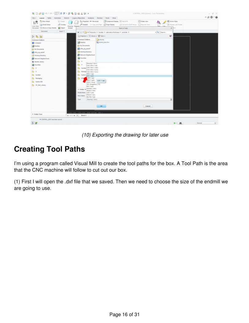
(10) Exporting the drawing for later use
Creating Tool Paths
I’m using a program called Visual Mill to create the tool paths for the box. A Tool Path is the areathat the CNC machine will follow to cut out our box.
(1) First I will open the .dxf file that we saved. Then we need to choose the size of the endmill weare going to use.
Page 16 of 31
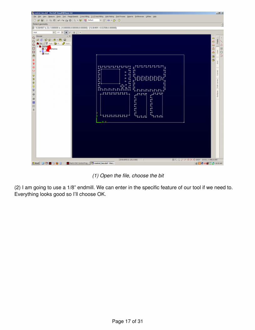
(1) Open the file, choose the bit
(2) I am going to use a 1/8” endmill. We can enter in the specific feature of our tool if we need to.Everything looks good so I’ll choose OK.
Page 17 of 31
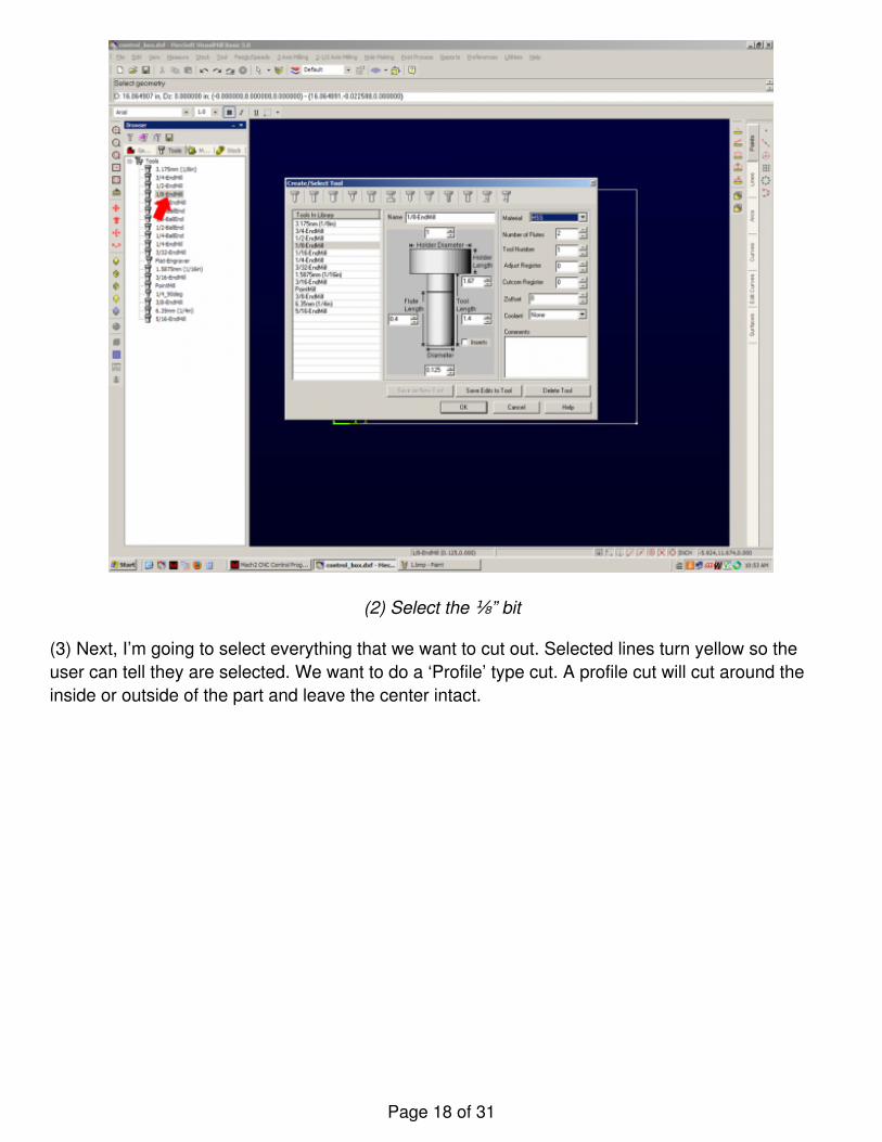
(2) Select the ⅛” bit
(3) Next, I’m going to select everything that we want to cut out. Selected lines turn yellow so theuser can tell they are selected. We want to do a ‘Profile’ type cut. A profile cut will cut around theinside or outside of the part and leave the center intact.
Page 18 of 31
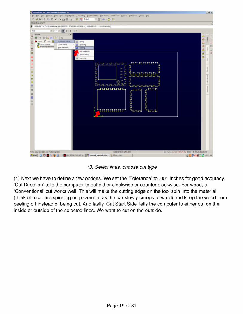
(3) Select lines, choose cut type
(4) Next we have to define a few options. We set the ‘Tolerance’ to .001 inches for good accuracy.‘Cut Direction’ tells the computer to cut either clockwise or counter clockwise. For wood, a‘Conventional’ cut works well. This will make the cutting edge on the tool spin into the material(think of a car tire spinning on pavement as the car slowly creeps forward) and keep the wood frompeeling off instead of being cut. And lastly ‘Cut Start Side’ tells the computer to either cut on theinside or outside of the selected lines. We want to cut on the outside.
Page 19 of 31
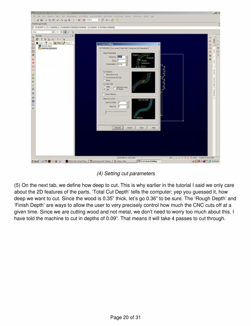
(4) Setting cut parameters
(5) On the next tab, we define how deep to cut. This is why earlier in the tutorial I said we only careabout the 2D features of the parts. ‘Total Cut Depth’ tells the computer; yep you guessed it, howdeep we want to cut. Since the wood is 0.35” thick, let’s go 0.36” to be sure. The ‘Rough Depth’ and‘Finish Depth’ are ways to allow the user to very precisely control how much the CNC cuts off at agiven time. Since we are cutting wood and not metal, we don’t need to worry too much about this. Ihave told the machine to cut in depths of 0.09”. That means it will take 4 passes to cut through.
Page 20 of 31
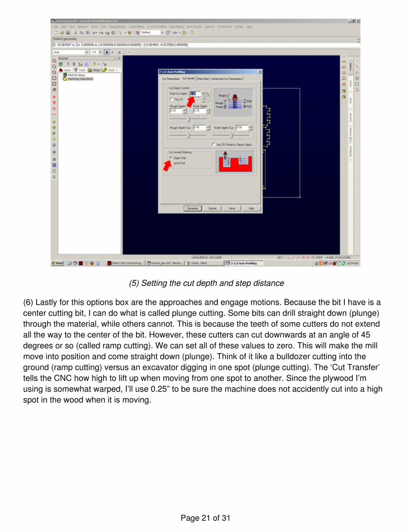
(5) Setting the cut depth and step distance
(6) Lastly for this options box are the approaches and engage motions. Because the bit I have is acenter cutting bit, I can do what is called plunge cutting. Some bits can drill straight down (plunge)through the material, while others cannot. This is because the teeth of some cutters do not extendall the way to the center of the bit. However, these cutters can cut downwards at an angle of 45degrees or so (called ramp cutting). We can set all of these values to zero. This will make the millmove into position and come straight down (plunge). Think of it like a bulldozer cutting into theground (ramp cutting) versus an excavator digging in one spot (plunge cutting). The ‘Cut Transfer’tells the CNC how high to lift up when moving from one spot to another. Since the plywood I’musing is somewhat warped, I’ll use 0.25” to be sure the machine does not accidently cut into a highspot in the wood when it is moving.
Page 21 of 31
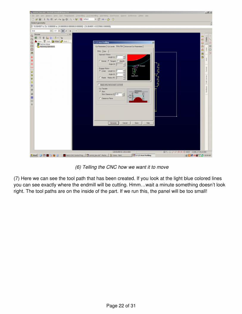
(6) Telling the CNC how we want it to move
(7) Here we can see the tool path that has been created. If you look at the light blue colored linesyou can see exactly where the endmill will be cutting. Hmm…wait a minute something doesn’t lookright. The tool paths are on the inside of the part. If we run this, the panel will be too small!
Page 22 of 31
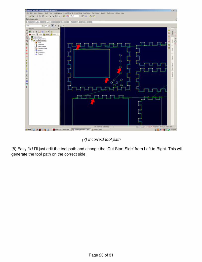
(7) Incorrect tool path
(8) Easy fix! I’ll just edit the tool path and change the ‘Cut Start Side’ from Left to Right. This willgenerate the tool path on the correct side.
Page 23 of 31
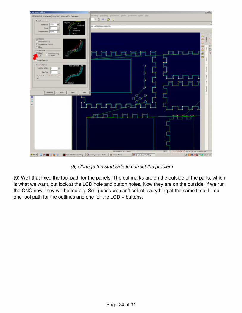
(8) Change the start side to correct the problem
(9) Well that fixed the tool path for the panels. The cut marks are on the outside of the parts, whichis what we want, but look at the LCD hole and button holes. Now they are on the outside. If we runthe CNC now, they will be too big. So I guess we can’t select everything at the same time. I’ll doone tool path for the outlines and one for the LCD + buttons.
Page 24 of 31
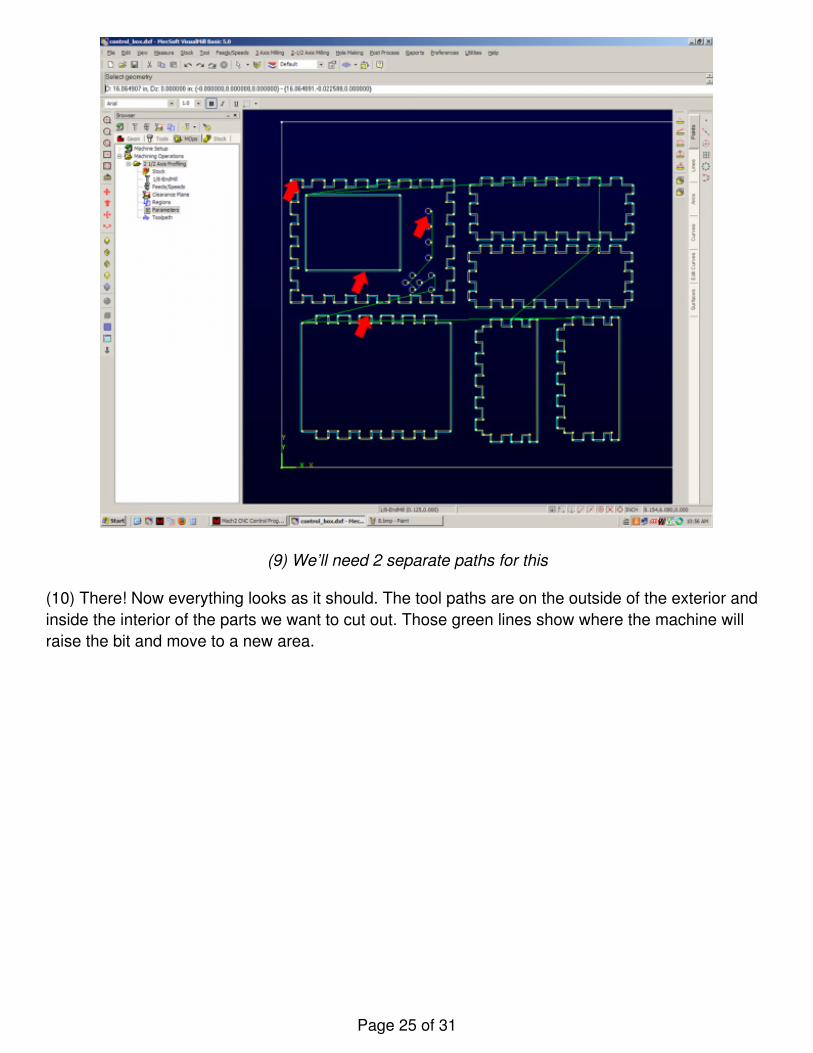
(9) We’ll need 2 separate paths for this
(10) There! Now everything looks as it should. The tool paths are on the outside of the exterior andinside the interior of the parts we want to cut out. Those green lines show where the machine willraise the bit and move to a new area.
Page 25 of 31
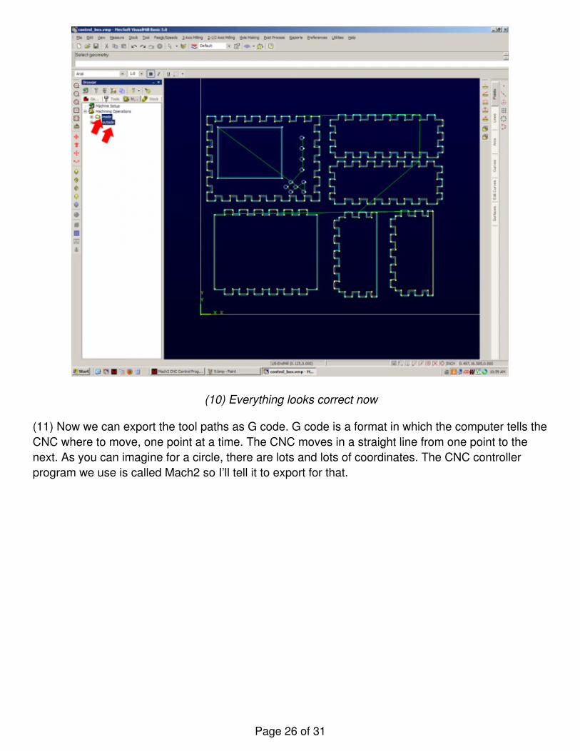
(10) Everything looks correct now
(11) Now we can export the tool paths as G code. G code is a format in which the computer tells theCNC where to move, one point at a time. The CNC moves in a straight line from one point to thenext. As you can imagine for a circle, there are lots and lots of coordinates. The CNC controllerprogram we use is called Mach2 so I’ll tell it to export for that.
Page 26 of 31
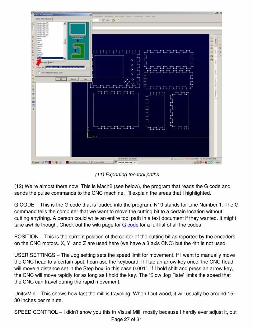
(11) Exporting the tool paths
(12) We’re almost there now! This is Mach2 (see below), the program that reads the G code andsends the pulse commands to the CNC machine. I’ll explain the areas that I highlighted.
G CODE – This is the G code that is loaded into the program. N10 stands for Line Number 1. The Gcommand tells the computer that we want to move the cutting bit to a certain location withoutcutting anything. A person could write an entire tool path in a text document if they wanted. It mighttake awhile though. Check out the wiki page for G code for a full list of all the codes!
POSITION – This is the current position of the center of the cutting bit as reported by the encoderson the CNC motors. X, Y, and Z are used here (we have a 3 axis CNC) but the 4th is not used.
USER SETTINGS – The Jog setting sets the speed limit for movement. If I want to manually movethe CNC head to a certain spot, I can use the keyboard. If I tap an arrow key once, the CNC headwill move a distance set in the Step box, in this case 0.001”. If I hold shift and press an arrow key,the CNC will move rapidly for as long as I hold the key. The ‘Slow Jog Rate’ limits the speed thatthe CNC can travel during the rapid movement.
Units/Min – This shows how fast the mill is traveling. When I cut wood, it will usually be around 15-30 inches per minute.
SPEED CONTROL – I didn’t show you this in Visual Mill, mostly because I hardly ever adjust it, butPage 27 of 31
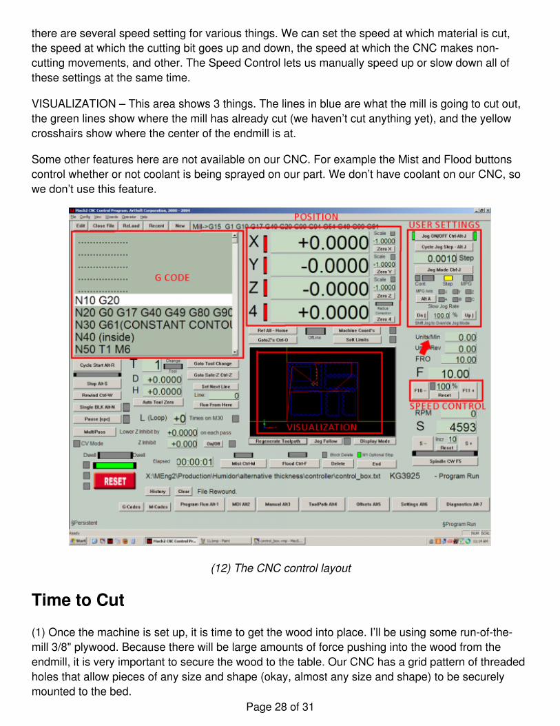
there are several speed setting for various things. We can set the speed at which material is cut,the speed at which the cutting bit goes up and down, the speed at which the CNC makes non-cutting movements, and other. The Speed Control lets us manually speed up or slow down all ofthese settings at the same time.
VISUALIZATION – This area shows 3 things. The lines in blue are what the mill is going to cut out,the green lines show where the mill has already cut (we haven’t cut anything yet), and the yellowcrosshairs show where the center of the endmill is at.
Some other features here are not available on our CNC. For example the Mist and Flood buttonscontrol whether or not coolant is being sprayed on our part. We don’t have coolant on our CNC, sowe don’t use this feature.
(12) The CNC control layout
Time to Cut
(1) Once the machine is set up, it is time to get the wood into place. I’ll be using some run-of-the-mill 3/8" plywood. Because there will be large amounts of force pushing into the wood from theendmill, it is very important to secure the wood to the table. Our CNC has a grid pattern of threadedholes that allow pieces of any size and shape (okay, almost any size and shape) to be securelymounted to the bed.
Page 28 of 31
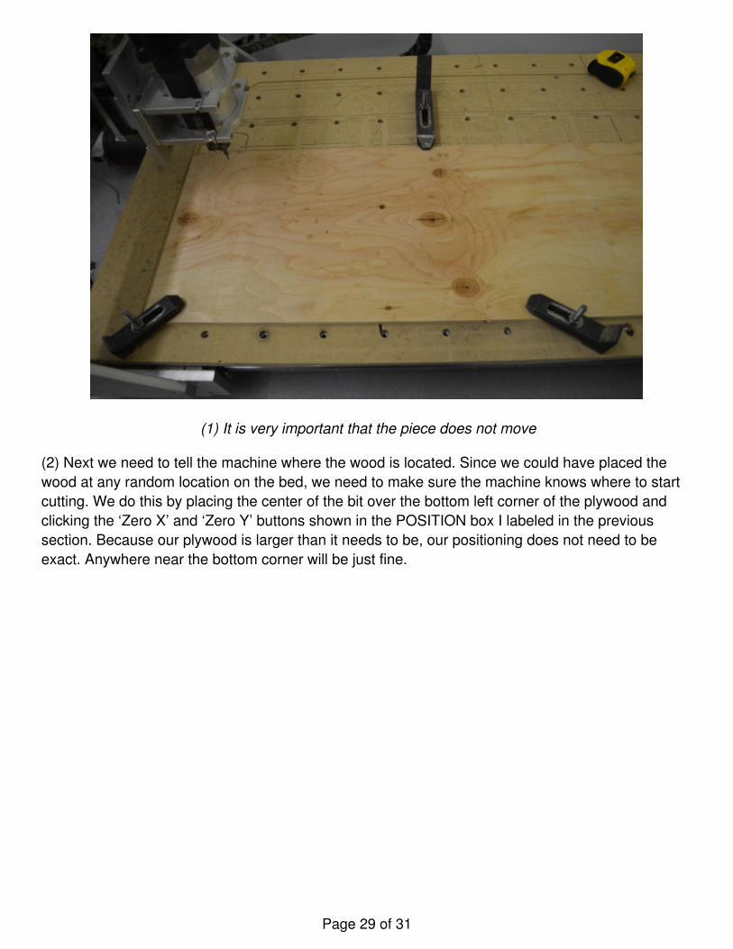
(1) It is very important that the piece does not move
(2) Next we need to tell the machine where the wood is located. Since we could have placed thewood at any random location on the bed, we need to make sure the machine knows where to startcutting. We do this by placing the center of the bit over the bottom left corner of the plywood andclicking the ‘Zero X’ and ‘Zero Y’ buttons shown in the POSITION box I labeled in the previoussection. Because our plywood is larger than it needs to be, our positioning does not need to beexact. Anywhere near the bottom corner will be just fine.
Page 29 of 31
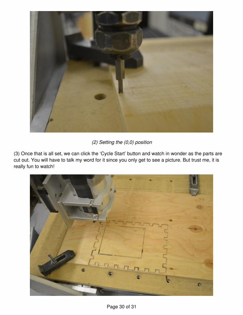
(2) Setting the (0,0) position
(3) Once that is all set, we can click the ‘Cycle Start’ button and watch in wonder as the parts arecut out. You will have to talk my word for it since you only get to see a picture. But trust me, it isreally fun to watch!
Page 30 of 31
(3) One piece of the box
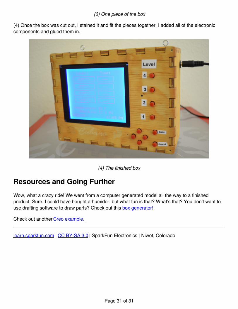
(4) Once the box was cut out, I stained it and fit the pieces together. I added all of the electroniccomponents and glued them in.
(4) The finished box
Resources and Going Further
Wow, what a crazy ride! We went from a computer generated model all the way to a finishedproduct. Sure, I could have bought a humidor, but what fun is that? What’s that? You don’t want touse drafting software to draw parts? Check out this box generator!
Check out another Creo example.
learn.sparkfun.com | CC BY-SA 3.0 | SparkFun Electronics | Niwot, Colorado
Page 31 of 31