Embed Size (px)
Citation preview

Authors Journal
Creating Control Systems for Sintering Processes in Tubular Rotary Kiln on Base Mathematical Model
Submit Manuscript | http://medcraveonline.com
Volume 2 Issue 1 - 2017
Chemical Engineering Professor, Saint-Petersburg Mining University, Russia
*Corresponding author: Sharikov IV, Saint-Petersburg Mining University, Russia, Email:
Received: July 15, 2017 | Published: July 21, 2017
Research Article
Author J 2017, 2(1): 00014
Abstract
We consider methods for modeling the temperature fields inside a rotary tubular kiln and in the lining of the oven. These models are used for creating a control system that supports the necessary technological parameters and reduces the heat loss through the kiln body to the environment. Two-dimensional modeling of the processes inside the kiln confirms the applicability of a unidimensional model to these processes. A simulation method for selecting a new design for the thermal-insulation elements, ensuring the reduction of the heat loss to the environment, and performing the required thermal processing is implemented using the ANSYS Fluent software package. A new type of insulation element is proposed, which reduces the heat loss from the kiln to the environment and reduces the temperature of the outer surface of the kiln. A system for monitoring the state of the lining using a thermal imager and a control system that ensures the consistency of the lining without stopping the kiln operation are developed.
Keywords: Tubular rotary kiln; Temperature fields; Lining; 3D modeling; Monitoring the state of the lining; Control of the sintering processes
IntroductionTubular rotary kilns (TRKs) are used in many fields, such as
metallurgy, the chemical industry, the production of construction materials, and the food industry [1-3]. When the kiln body rotates, the particles of the solid phase move along complex trajectories. A whole series of scientific papers are devoted to the mathematical description of the motion of solid particles [4-6]. The movement of fine particles of the solid phase is also affected by the motion of the gas phase inside the furnace [7-11]. The lining of a TRK plays an important role in the implementation of the basic technological functions of the TRK and ensuring its economical effectiveness. The efficiency and integrity of the lining operation at the selected compliance level depends on the mode of processing and the heat loss to the environment.
During TRK operation, the heat lost through the outer surface to the environment accounts for up to 10% of the total consumed energy [1-3]. The lining protects the steel furnace and the operating staff from the high temperatures and the furnace environment. It provides the required density of gas in the working chamber of the furnace and a complete seal to maintain the pressure needed for the process. The lining is one of the major structural elements of furnaces. It enables the implementation of technological and thermal processes in the furnace environment in the presence of mechanical stress, while maintaining the geometric shape of the internal furnace space, as well as its construction and mechanical strength, over time. The lining is closely related to the charge, the products generated, and the furnace environment [8]. Owing to the lack of thermal-insulation materials with sufficiently low thermal conductivity and high mechanical strength, researchers must search for new designs of heat-insulating elements that ensure minimal heat loss to the environment [12-14]. In addition,
for the stable operation of kilns, it is necessary to create a system that allows the control of the state of the lining during its normal operation and the maintenance of its insulating properties. Thus, the creation of new designs of heat-insulating elements together with a monitoring and control system is very important for the successful operation of a wide range of industrial processes in TRKs.
In alumina production, TRKs are used to sinter bauxite and nepheline and induce the calcination (decomposition) of aluminum hydroxide. The sintering of bauxite in a rotary kiln is considered. As revealed by a previous analysis of the processes occurring in a TRK using experimental data on the kinetics of the heat generation in the calorimeter heat flux [7] and the establishment of a one-dimensional mathematical model TRK [8], according to the temperature of the hot flue gases that heat the charge and the changes in the charge, the kiln can be divided into the following four zones. The first zone-dewatering and drying-is at the top (cold) side. The flue-gas temperature ranges from 200 °C to 1,250 °C, and the batch temperature ranges from 20 °C to 700 °C. All the moisture is removed in this zone. In the second zone-calcination-the gas temperature changes from 1,250 °C to 1,400 °C, and the charge temperature changes from 700 °C to 1,000 °C. In this zone, the charge is fully decomposed. The third zone-sintering-has the highest gas temperature of 1,600 °C-1,650 °C, and the charge temperature reaches 1,200 °C-1,650 °C. Here, the decomposition of the soda is finished, and the cake formation occurs. This zone is located within the length of the fuel combustion flame.
The fourth zone-cooling-is located in the lowest part of the drum furnace for firing the torch. Here, the gas temperature decreases to 1,500 °C -1550 °C. In a refrigerator, the cake is cooled
Creating Control Systems for Sintering Processes in Tubular Rotary Kiln on Base Mathematical Model
2/7Copyright:
©2017 Sharikov
Citation: Sharikov IV (2017) Creating Control Systems for Sintering Processes in Tubular Rotary Kiln on Base Mathematical Model. Author J 2(1): 00014.
to 60-70 °C. The sintering process is characterized by the exhaust-gas temperature, the composition of the material flow in the kiln, and the cake appearance. During a typical process, the flue-gas temperature in the exhaust gas pipe of the kiln is 180 °C-200 °C. These conditions allow the stable operation of electric filters and fans. The normal cake material has a dark gray color, with pieces measuring 40-50 mm. In the exhaust gases, the content of CO and O2 should not exceed 0.6%, and the CO2 content should be in the range of 25-27% [8].
In the rotary kiln for the calcination of aluminum hydroxide, temperature (technological) zones corresponding to specific stages of the conversion of the initial hydroxide are observed. Analysis of the gas-flow material temperature and the furnace length reveals four zones. In the drying zone-the coldest upper part of the furnace-the gas temperature changes from 300 °C to 600 °C, and the hydroxide temperature changes from 40 °C to 200 °C. Here, the moisture absorbent hydroxide is completely evaporated. The calcination zone is in the middle part of the kiln. In this zone, the gases are heated to temperatures of 600 °C -1,050 °C, and the hydroxide temperature ranges from 200 °C to 950 °C. Thus, there is a removal of chemically bound water, and the hydroxide is transformed into anhydrous gamma-alumina. The glowing zone is located in the area of the torch burning fuel. Here, the gamma-alumina and alpha-alumina are recrystallized. The gas temperature is 1,050 °C -1,400 °C, and the alumina temperature is 950 °C -1,250 °C. Sometimes, the kiln-drum diameter is slightly larger than the diameter of the drums in the other zones. This reduces the moving speed of the material and increases the duration of its stay in the glowing zone. The cooling zone is in the lower part of the furnace, where the temperature of the alumina is reduced from 1,250 °C to 1,000 °C. Here, the alumina is placed into the refrigerator. With complete combustion and no air leaks in the flue gas, the contents of CO2 and CO should be 13-15% and <0.8%, respectively. The calcined alumina should contain a certain amount of alpha-alumina.
To confirm the distribution of the reactions zones along the length of the TRK, we employ 2D modelling.
Materials and MethodsMain method of study in this research method mathematical
modeling has been selected.
Two-dimensional (2d) mathematical modelling of temperature fields in TRK
To determine the flow patterns, temperature distribution, and concentrations of O2 and CO2 in the furnace, we used the software package COMSOL 3.5. COMSOL for describing the computational fluid dynamics based commercial software Fluent 6.3 is used to investigate the pressure drop as well as the gas-solid flow behavior in a bypass pneumatic conveying system. Multiphysics is a powerful interactive environment for the modeling and calculation of most scientific and engineering problems using partial differential equations (PDEs) and the finite-element method [8]. This software package can extend the standard models using one differential equation (application mode) to multiphysics models for the calculation of related physical phenomena because of the built-in physical mode, where the PDE
is defined according to the physical properties and conditions-such as the thermal conductivity, heat capacity, heat-transfer coefficient, and bulk power-depending on the physical partition. The transformation of these parameters in the coefficients of mathematical equations is actualised automatically. Interaction is possible through the graphical user interface (the standard manner) or via programming with scripts in the COMSOL Script language or MATLAB. Using the software package COMSOL 3.5a, the thermal conditions of the furnace are investigated according to the power and angle of the torch, the concentration in the fuel and oxidizing flow, and the oven speed. The problem of the turbulent motion of a multicomponent mixture of reacting gases has been solved. A standard k-ε model is used as the turbulence nidek. For the description of the gas combustion, a two-step reaction scheme is selected, with the use of models that break the vortex. For the construction of the oven, a computational grid consisting of two blocks built in the local cylindrical coordinate systems is used.
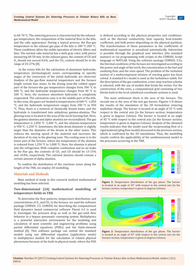
The main settlement block is the area of the furnace. The second one is the area of the exit gas burner. Figures 1-8 shows the results of the simulation of the 2D formulation sintering nepheline charge. The burner is located at an angle of 25 °C with respect to the central axis (in the furnace section; temperature is given in degrees Celsius). The burner is located at an angle of 45 °C with respect to the central axis (in the furnace section; temperature is given in degrees Celsius). Analysis of the obtained results indicates that the model used the reciprocating flow of a rigid material (plug flow model) discussed in the previous section, which is confirmed by the 2D simulations. Thus, the modelling results confirm the applicability of the unidimensional model to the processes occurring in the TRK.
Figure 1: Temperature distribution of the gas phase. The burner is located at an angle of 25° with respect to the central axis (in the furnace section; temperature is given in degrees Celsius).
Figure 2: Temperature distribution of the gas phase. The burner is located at an angle of 45° with respect to the central axis (in the furnace section; temperature is given in degrees Celsius).

Creating Control Systems for Sintering Processes in Tubular Rotary Kiln on Base Mathematical Model
3/7Copyright:
©2017 Sharikov
Citation: Sharikov IV (2017) Creating Control Systems for Sintering Processes in Tubular Rotary Kiln on Base Mathematical Model. Author J 2(1): 00014.
Mathematical modeling of thermal fields in fragment of lining of TRK
One of the main factors determining the thermal efficiency of
the kiln is the quantity of heat-resistance lining, which is used in the rotary kiln to prevent heat loss through the body to the environment, yielding a total heat of combustion as high as 10-15% [12-14]. The absence of a fast heat-resistant material with good thermal-insulation properties to a large extent determines the direction of the work for creating a lining with high thermal resistance through the introduction of additional fibrous insulation material, which is achieved by changing the shape of the refractory. The heat insulator can be a fibrous structure, such as mullite-silica wool, containing inorganic additives, basalt fiber, and similar structures that can be used at temperatures up to 1,600 °C. In this case, cells filled with the insulation material are placed between the refractory and the oven [12-14].
The greatest reduction of the heat loss in the furnace environment and weight lining can be achieved through the installation of specifically shaped refractory materials in the high-temperature zone of the furnace, which also provides a large heat transfer with material and decreased thermal mass unit [13,14]. Figure 9 shows the design of the thermal insulation, which is based on the firebrick cabinet, with legs formed by cells. Under the mechanical and thermal loads that occur during operation, the reduced form provides better preservable mechanical stability of the refractory bricks and ensures a high thermal efficiency. The objective of this part of the study is to investigate the options for
Figure 3: Temperature distribution in the central cross section of the furnace, in the case of a horizontally positioned burner (in the furnace section; temperature is given in degrees Celsius).
Figure 4: Distribution of CO (kmol/m3) in the case of a horizontally positioned burner (in the furnace section, with the torch).
Figure 5: Distribution of O2 (kmol/m3) with the burner at an angle of 25° with respect to the central axis (in the furnace section, with the torch).
Figure 6: Distribution of O2 (kmol/m3) with the burner at an angle of 45° with respect to the central axis (in the furnace section, with the torch).
Figure 7: Temperature distribution of the solid phase in the cross-section of the furnace (temperature is given in degrees Celsius).
Figure 8: Temperature distribution of the solid phase in the longitudinal section of the kiln (temperature is given in degrees Celsius).

Creating Control Systems for Sintering Processes in Tubular Rotary Kiln on Base Mathematical Model
4/7Copyright:
©2017 Sharikov
Citation: Sharikov IV (2017) Creating Control Systems for Sintering Processes in Tubular Rotary Kiln on Base Mathematical Model. Author J 2(1): 00014.
mounting shaped refractory linings of various configurations, considering both the thermal efficiency and structural reliability due to the refractory thermo mechanical tension.
The task is to obtain the temperature fields and develop methods for calculating the temperature fields in the body of the refractory. Data on the temperature field in the masonry stove are obtained via mathematical modeling. The heat balance is applied for calculating the thermal fields in a Cartesian coordinate system, as follows:
2 2 2
2 2 2
t t t t qvC Cx y z
λτ ρ ρ
∂ ∂ ∂ ∂ = + + + ∂ ∂ ∂ ∂
(1)
t - system temperature, K
τ - lining heating time, s
λ- heat conductivity of lining material, W/(m·K)
ρ- lining-material density, kg/m3
С- lining-material heat capacity, J/(kg·K)qvCρ
- term accounting for the insert source of thermal energy,
K/s
For solving the differential equations, the initial and boundary conditions for the high-temperature sintering zone of a rotary kiln are used [8-10].
Temperature of the inner surface of the rotary kiln: tin = 1,873 K
Temperature of the environment: tenv = 300 K
Thermal conductivity of refractory fireclay, as a function of the temperature: (0.72 0.0005 )1.16cham tλ = + ⋅
где t - temperature chamotte refractory material, °C
Thermal conductivity of basalt fiber: λbas = 0.06 W/(m ∙ K)
Density of chamotte: ρcham = 1.800 kg/m3
Density of basalt fiber: ρbas = 200 kg/m3
Convective heat-transfer coefficient for the outside of the kiln: α = 30 W/ (m2∙K) [15,16].
The thickness of the lining depends on the technological requirements of the rotary kiln [8].
Results and DiscussionsThe differential equations are solved using the software
package ANSIS 14.0, via the finite-element method. The package ICEM CFD 14.0 is used to generate finite-element meshes, as shown in Figure 10 & 11. According to (1), the temperature fields for the fireclay refractory lining and the new lining are obtained, as shown in Figure 12 & 13, respectively.
q = 6,427 W/m2: heat flux through the outer surface of the kiln
Text = 514 K: average temperature of the outer surface of the kiln
q = 2,671 W/m2: heat flux through the outer surface of the kiln
Text = 389 K: average temperature of the outer surface of the kiln
Figure 9: Design of the rotary kiln lining: A- using only chamotte, B- using chamotte and a fiber structure; 1- fiber structure, 2- chamotte.
Figure 10: Finite-element mesh for the standard construction lining. The number of items is 46,672, the number of nodes is 8,153, and the average size of a finite element is 0.02 m.
Figure 11: Finite-element mesh lining for the new design. The number of items is 47,693, the number of nodes 8,124, and the average size of a finite element is 0.02 m.

Creating Control Systems for Sintering Processes in Tubular Rotary Kiln on Base Mathematical Model
5/7Copyright:
©2017 Sharikov
Citation: Sharikov IV (2017) Creating Control Systems for Sintering Processes in Tubular Rotary Kiln on Base Mathematical Model. Author J 2(1): 00014.
According to the thermograms, the following conclusions can be drawn regarding the new lining design:
a) Creating a layer of basalt fibers on the outer edge of the fireclay lining yields temperature of 125 K on the outer surface of the kiln.
b) The heat-flux reduction for the new design is 2.4 times lower than that for the standard lining.
c) The new design reduces the fuel consumption by reducing the heat loss to the environment. Harmful emissions are also reduced.
d) The new design reduces the share of the lining of the heat loss proportional to the reduction of the heat flux.
To check the adequacy of the model, a study is performed using JSC ‘Basel Cement.’ A thermal imager (OptrisPI-230) is used to survey the temperature field of the lining of a rotary kiln. The results are presented in Figure 14. The thermal image shows that the surface temperature of the rotary kiln is equal to the temperature of the lining surface, according to the calculations using the ANSYS Fluent software. The results confirm the adequacy of the model. The mathematical model of the lining of a rotary kiln allows us to estimate the temperature fields inside the lining and on its outer surface and use these to build process control firing according to the condition of the lining. The furnace lining is an inseparable and integral part of the chemical-thermal
furnace ‘material-medium-lining’ of the system. Therefore, it should be considered only in conjunction with the other elements of the kiln system. In the rotary kiln lining, the skull is covered with a layer that provides protection against thermal radiation and the moving charge. The skull thickness must be supported on a constant level. If the surface temperature exceeds the value set by the technological requirements, the thickness of the skull is reduced, the lining is exposed, and the thermal conditions inside the furnace must be changed [13].
The skull in a rotary kiln is formed by inserting a moving charge in the kiln space. Typically, at a temperature below 1,600 °C, a stable to thermomechanical destruction skull is formed on the surface of the skull. As the temperature inside the kiln increases above 1,600 °C, the skull viscosity decreases, resulting in spall and the exposure of the lining [13,14]. The changes in the thickness and exposure of the lining are shown in Figure 15. A temperature increase leads to the formation of a viscous structure, reducing the forces of adhesion of the skull and the lining. Furthermore, the clutch burnout of the oven occurs in this zone, which can disrupt the kiln operation and necessitate repairs (Figure 16). Currently, the overheating zones of rotary kilns are controlled manually, at set time intervals, using a pyrometer [13]. The disadvantage of this method is the estimation of the temperature state at the furnace lining, which may lead to the inability to detect zones of overheating and the destruction of the lining.
The purpose of this part of the study is to develop a system that allows the continuous monitoring of the lining and sends signals to the operator in real time. The system is based on computer vision. Sensors measure the thermal field on the surface of the furnace, and an imager transmits video signals to an automatic control system (ACS), which performs an analysis to identify the overheating zone of the furnace.
The circuit monitors the status of the lining of the rotary kiln via infrared sensors located along the length of the kiln in the hottest areas. These sensors are for thermal imaging and measure the 2D temperature field on the surface of the kiln lining. A digital signal from the infrared detector is transmitted to the control
Figure 12: Temperature field for the standard design of the kiln lining.
Figure 13: Temperature field for the proposed design of the kiln lining.
Figure 14: Temperature field on the surface of a rotating furnace lining.

Creating Control Systems for Sintering Processes in Tubular Rotary Kiln on Base Mathematical Model
6/7Copyright:
©2017 Sharikov
Citation: Sharikov IV (2017) Creating Control Systems for Sintering Processes in Tubular Rotary Kiln on Base Mathematical Model. Author J 2(1): 00014.
unit of the system and is used to analyse the thermal load on the lining. The next signal from the infrared detector is transmitted to the operator control mode technology so that it can decide to change the mode of the radiation inside the furnace chamber for preventing overheating. The components presented in Figure 17 allow the automatic control of the heat load of the lining. The imager performs the function of the sensor space temperature field on the surface of the rotary kiln. The video signal from the imager is converted into a matrix Tm, characterizing the thermal field on the surface of the lining at the time τm [17,18]. This matrix can be represented as
1,1 1,
,1 ,
...... ... ...
...
n
m
m m n
t tT
t t
= ,
(2)
where the elements tm,n are the temperatures on the surface
of the kiln. Each element of the matrix corresponds to a separate group of pixels in the image produced by the thermal imager. The signal enters the comparator unit, where there is a comparison matrix Tm values given matrix Tconst, which has the form
1,1 1,
,1 ,
...... ... ...
...
n
m
m m n
t tT
t t
= ,
(3)
where the elements of the matrix represent the maximum permitted temperature at the surface of the kiln.
If the five elements tm,n vertical to the column-matrix values
exceed the corresponding values of the matrix ,const
m nT , there is
overheating in the lining of the rotary kiln zone [17,18].
In this case, the operator receives a notification of the occurrence of local hotspots. He may decide to change the radiation regime in the kiln or leave it unchanged, depending on the requirements of the technological regime [13]. Then, the signal enters the controller unit, which activates an actuator that controls the burner. The actuator changes the position of the torch and the thermal conditions inside the kiln chamber. This system controls the lining temperature of the rotary kiln and provides an on-line time regime to obtain information regarding the presence of zones of overheating and take quick action to reduce the heat load on the hot spots, thereby extending the service life of the lining and decreasing the repair time for the kiln.
Conclusiona) The distribution temperature fields in a TRK were studied
using kinetic data and the software package ANSYS Fluent.
b) The modelling results confirmed the applicability of the
Figure 15: Chipping skull in a rotary kiln.
Figure 16: System of control condition for the lining of the rotary kiln (1, 2, N- infrared detectors; 3- actuator; 4- controller).
Figure 17: ACS for controlling the thermal load of the lining.

Creating Control Systems for Sintering Processes in Tubular Rotary Kiln on Base Mathematical Model
7/7Copyright:
©2017 Sharikov
Citation: Sharikov IV (2017) Creating Control Systems for Sintering Processes in Tubular Rotary Kiln on Base Mathematical Model. Author J 2(1): 00014.
unidimensional model for describing the processes inside the kiln.
c) The heat-distribution processes in the lining of the TRK were analysed together with the flow of technological processing inside the charge in the kiln.
d) A mathematical model of the process and the proposed construction of the heat-insulating a novel design of the heat-insulating elements reducing the heat loss to the environment.
e) The proposed design allows the reduction of the heat loss and the temperature of the outer surface.
f) A system for scanning the surface temperature and energies was proposed. It allows us to define a mathematical model with regard to the internal destruction of the protective layer and to guide the dust stream in these places, regenerating the protective-layer skull without stopping the kiln.
References1. Krivandin VA (2002) Heat metallurgical production. In: Krivandin
AV & Arutyunov VA (Eds.), Maintenance of Internal Security Act, India, pp. 608.
2. Voskoboynikov VG, Kudrin VA, Yakushev AM (2005) Total Metallurgy. University textbook M, Metallurgy.
3. Boateng AA (2006) Rotary Kilns: Transport Phenomena and Transport Processes. Butterworth-Heinemann, USA, pp. 1-368.
4. Khanpour M, Zarrati AR, Kolahdoozan M, Shakibaeinia A, Jafarinik S (2016) Numerical modeling of free surface flow in hydraulic structures using Smoothed Particle Hydrodynamics. Applied Mathematical Modelling 40(23-24) 9821-9834.
5. Li D, Wang L, Wang Q, Liu G, Lu H, et al. (2016) Simulations of dynamic properties of particles in horizontal rotating ellipsoidal drums. Applied Mathematical Modelling 40(17-18): 7708-7723.
6. Wang ZB, Chen R, Wang H, Liao Q, Zhu X, et al. (2016) An overview of smoothed particle hydrodynamics for simulating multiphase flow. Applied Mathematical Modelling 40(23-24): 9625-9655.
7. Sharikov Y, Sharikov F, Titov O (2015) Optimization of process conditions in a tubular rotary kiln with applying TG / DSC technique and mathematical modeling. J Therm Anal Calorim 122: 1029-1040.
8. Sharikov Y, Sharikov F, Titov O (2013) Mathematical modeling of processes in the tubular rotary kiln. LAMBERT Academic Publishing, 102.
9. Marias F, Roustan H (2005) Pichat A: Modelling of a rotary kiln for the pyrolysis of aluminium waste. Chem Eng Sci 60(16): 4609–4622.
10. Pisaroni M, Sadi R, Lahaye D (2012) Counteracting ring formation in rotary kilns Journal of Mathematics in Industry. 2:3.
11. Marias F, Roustan H (2005) Pichat A: Modelling of a rotary kiln for the pyrolysis of aluminium waste. Chem Eng Sci 60 (16): 4609–4622
12. Insulation (2008) Materials. Structure. In: Kochergin SM (Eds.), Stroyinform, USA, pp. 1-440.
13. Sharikov YV, Marcus A (2014) Mathematical modeling of heat transfer through the lining of a rotary kiln. Metallurgist 57(11-12): 50-54.
14. Sharikov YV, Marcus A (2013) Mathematical modeling of heat transfer body of the tubular structure, with respect to the pipeline metallurgical units. Notes Mining Institute, USA, 5: 54-57.
15. Kutateladze SS (1990) Heat transfer and hydraulic resistance. In: Kutateladze SS (Eds.), Gosenergoizdat, USA, pp.1-367.
16. Michael C, Wendl (2012) Theoretical Foundations of Conduction and Convection Heat Transfer. The Wendl Foundation, USA, pp. 1-226.
17. Gonzalez R (2006) Digital image processing in an environment MatLAB. In: Gonzalez R & Woods R (Eds.), Dorling Kindersley Pvt Ltd, USA, pp. 1-578.
18. Vizilter Y (2010) Processing and analysis of images in machine vision tasks. In: Vizilter JV (Eds.), Fizmatkniga, USA, pp. 1-672.