Embed Size (px)
Citation preview
Journal of Stress Analysis
Vol. 1, No. 1, Spring − Summer 2016
Creep Analysis of the FGM Cylinder under Steady-state
Symmetric Loading
N. Habibia,∗, S. Samawatib, O. Ahmadica,∗Mechanical Engineering Department, University of Kurdistan, Iran.bMechanical Engineering Department, Khajeh Nasir Toosi University of Technology, Iran.cMechanical Engineering Department, Urmia University, Iran.
Article info
Article history:Received 2016.04.26Received in revised form2016.07.01Accepted 2016.07.19
Keywords:Exact SolutionRotary CylinderCreepNavier Equation
Abstract
In this paper, a semi-analytical method for creep investigation and elasticbehavior of FGM rotary cylinders has been introduced. Assumed cylinder wasdivided to numerous finite width layers with constant thermodynamic prop-erties in each layer. Governing equations converted to ordinary differentialequations with constant coefficients by applying continuity conditions betweenlayers and boundary conditions of disc in derived equations, then theseequations could be solved by a prepared computer code. For thermo-elasticpart, variation of dimensionless radial and circumferential strains versusdimensionless radius investigated for several power of FGM material. Also,verification of results was done. For creep part, variation of dimensionlessradial and circumferential strain rates versus dimensionless radius was studiedfor different temperatures and limited timeframe. Changes of radial andcircumferential strain rates versus radius were investigated and the resultswere validated. Finally, the effects of various parameters on creep behavior ofrotary cylinder in several examples was examined.
Nomenclature
κ, ζ Material constants for creep u Radial displacementu Radial displacement rate ν Poison ratioq Constant of material ∆T Temperature gradient in cylinderL, h Length and walled thickness of cylinder n Power of functional graded materialRi, Ro Inner and outer radii of cylinder ω Angular velocity of cylinderZ A column matrix εrr, εθθ Radial and tangential strainsz, θ, r Components of axial, circumferential
and radial directionsPr Typical material property
Po, Pi Property at the inner and outer surfacesof cylinder
εrr, εθθ Strains rate of radial and tangential
˙σrr, ˙σθθ Radial and tangential stresses rate ˙σzz, Axial stress rateσeff Effective stress Zk
1 , Zk2 Unknown coefficients of the layer k
τ Creep time ∆τ Time stepE(r), υ(r) Elastic modulus and Poison ratio in an
arbitrary radiusεrr,c Creep strain rate in radial direction
∗Corresponding author: N. Habibi (Associate Professor)E-mail address: [email protected]
9
εθθ,c Creep strain rate in tangential direction εcr, εcθ Creep strain in radial and tangential di-rections
Ei, Eo Inner and outer lateral surfacesdimen-sionless elasticity modulus
E(r) Dimensionless elasticity modulus in anarbitrary radius
ρin, ρout Inner and outer lateral surfaces densityof cylinder
αin, αout Inner lateral and outer surfaces thermalexpansion coefficient of cylinder
υin, υout Inner and outer lateral surfaces poisonratio of cylinder
Kin,Kout Thermal conductivity coefficient in in-ner and outer lateral surfaces of cylin-der
Al, Cer Aluminum and Cerami ∆Ti,∆To Temperature gradient in inner andouter lateral surfaces of cylinder
1. Introduction
Recently, by development and growth of powerful en-gines, turbines, reactors and other machinery, heat andmechanically resistant materials are required. Becauseof some existing issues in different industries for sub-jecting materials to high heat stresses, Japanese mate-rial scientists in Sundae, for the first time, suggestedFG (Functional Graded) materials as high heat resis-tant materials [1]. FG materials are composite ma-terials with inhomogeneous microstructure that theirmechanical properties change from plate to plate inthe body smoothly and have certain variations in thematerial properties. According to composition type,mechanical properties have also continuous variationsin thickness direction. Such materials have more effec-tive mechanical properties than layer composite ma-terials, because of continuous composition of formerones. These materials are used in the following applica-tions: In various industries including aerospace (Capemissiles, jet engines), the automotive industry (Hybridcars), marine industries, construction of advanced tur-bines.
Generally, to obtain main results, stress in plate,disc, and cylinder should be determined. Sing and Rey[2,3] described steady-state creep analysis of a inho-mogeneous rotary cylinder made from composite ma-terials, including silicon carbide particles in special alu-minum matrix, by using Hill yielding criterion and Nor-ton law. Material creep parameters of their assumeddisc were changing with radius because of proportionalvariation in composition of silicon carbide particles inthe aluminum matrix. Howie shen investigated post-buckling analysis of cylinder panels axially loaded inthermal ambient. This analysis was conducted for FGcylinder panel with finite length [4]. Leo Jacob [5] stud-ied thermoelastic analysis and optimization of platesand FG shells. He used meshless and finite elementmethods.
Li Yu et al. [6] presented a semi-analytical methodfor analysis of thermoelastic behavior of hollow cylin-ders made from targeted materials. They consideredconstant material properties by dividing cylinder toseveral cylinders in the radial direction and simplifyingequations to solve. Gupta and Singh [7] had studied
anisotropy effect of FG steady-state creep.In the other study [9] for rotating cylinder, all of
the material properties were assumed to be exponen-tially graded along radius. A semi-analytical solution(the method of successive approximation) was devel-oped to obtain history of stresses and deformationsduring creep evolution of the EGM rotating cylinder. Acomprehensive comparison was made between creep re-sponse of homogenous and non-homogenous cylinders.It has been concluded that the material in-homogeneityparameter has a considerable effect on the thermoelas-tic and creep response of rotating cylinders made ofEGMs.
Ghannad et al. [10] investigated an elastic analysisfor FGM thick cylindrical shells having axially linearvarying thickness utilizing the FSDT. The governingequations in the axisymmetric case and elasto-staticstate, which are a system of ODE with variable coef-cients, were solved analytically using the MAM of theperturbation theory.
Nejad and co-workers [11] investigated time-dependent thermo-elastic creep response for isotropicrotating thick-walled cylindrical pressure vessels madeof functionally graded material. Moreover, a semi-analytical method was applied for the purpose of elasticanalysis of rotating thick cylindrical shells with vari-able thicknesses made of axially functional graded ma-terial under non-uniform pressure and derived a semi-analytical solution for determination of displacementsand stresses in a thick cylindrical shell with variablethicknesses under non-uniform pressure [12-14]. Inthe study of Jabbari and co-workers [15], the materialproperties, except the Poisson’s ratio, were assumed tovary with the power law function in the axial direc-tion of the pressure vessel. The effects of higher-orderapproximation on the radial and axial displacements,Von-Mises, and shear stresses were studied. Also, theeffects of mechanical and thermal loading, thicknessprofile type, and gradient index on the mechanical be-havior of the cylindrical pressure vessel were examined.
Loghman et al. [16] using Burgers viscoelastic creepmodel, studied history of strains, stresses, and displace-ments of a rotating cylinder made of polypropylenereinforced by multi-walled carbon nanotubes (MWC-NTs) under magneto-thermo-mechanical loading; it
Creep analysis of the FGM cylinder under steady-state cymmetric loading: 9–21 10
was discoverded that radial displacement, tangentialstrain, and absolute values of radial strain increasewith time at a decreasing rate, finally, approaching thesteady-state conditions; effective stresses decreasing atthe inner and increase at the outer surface of the cylin-der.Garg and co-workers [17] investigated the steady-statecreep in a rotating FGM disc with linearly varyingthickness by using von-Mises yield criterion; it wasshown that when the FGM disc is subjected to a radialTG (Thermal Gradient), with temperature and radiusincreasing simultaneously, the radial stress increasesover the entire disc but the tangential and effectivestresses increase near the inner radius and decrease to-ward the outer radius. Furthermore, the creep strainrates in rotating FGM disc could be significantly re-duced when the disc is subjected to a radial TG, withtemperature and radius increasing simultaneously.
In the other research [18] distributions of stress andstrain components of rotating discs with non-uniformthickness and material properties subjected to thermo-elastoplastic loading were obtained by semi-exact Liaoshomotopy analysis method (HAM) and finite elementmethod (FEM). The materials were assumed to beelastic-linear strain hardening and isotropic. The anal-ysis of rotating disk was based on Von Mises yield cri-terion. A 2D plane stress analysis was used. The dis-tribution of temperature was assumed to have powerforms with the hotter point located at the outer surfaceof the disk.
Garg et al. [19] studied the steady-state creep be-havior of a rotating FGM disc having linearly vary-ing thickness. The disc was assumed to be made offunctionally graded composite containing non-linearlyvarying radial distribution of silicon carbide particlesin a matrix of pure aluminum. It was observed thatthe radial and tangential stresses induced in the FGMdisc decrease throughout with the increase in thicknessgradient of the disc. The strain rates also decrease withthe increase in thickness gradient of the FGM disc, witha relatively higher decrease near the inner radius. Theincrease in disc thickness gradient results in relativelyuniform distribution of strain rates and hence reducesthe possibility of distortion in the disc.
Khanna and co-workers studied [20] steady-statecreep in a rotating Al-SiCp disc with different thick-ness profiles and reinforcement (SiCp) gradients. Theyassumed the disc material to creep according tothreshold-stress based law and yield following Trescacriterion. The stress and strain rates in the discwere calculated by using the disc equilibrium equa-tions along with creep constitutive equations. It wasobserved that on the increase of the disc thickness gra-dient, the radial stress declines towards the inner ra-dius but increases towards the outer radius, whereasthe tangential stress decreases over the entire radius.Also, the composite disc having higher thickness and
higher reinforcement gradients exhibits lesser distor-tion.
Previous works on this topic have been done morefor rotary discs, but in the present research, cylindermade of functional graded materials was investigatedthat this issue is new in terms of geometry. To solvethis problem, the semi-analytical method was usedwhich is different from the method used in other re-searches.
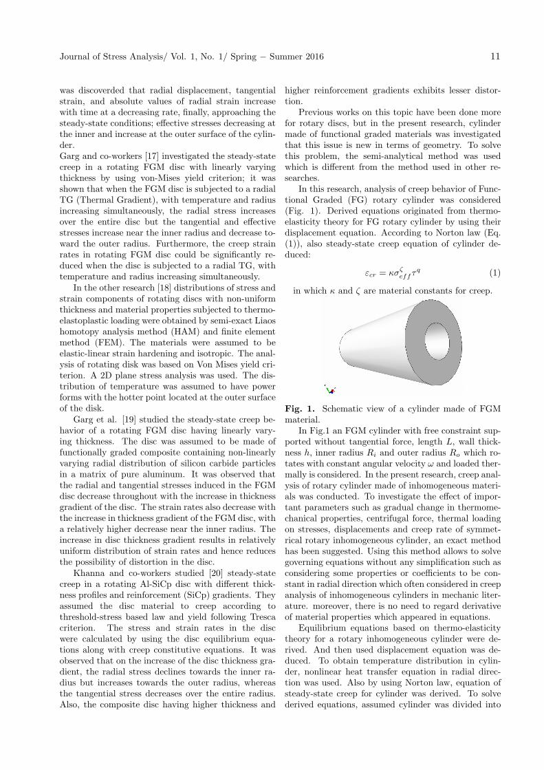
In this research, analysis of creep behavior of Func-tional Graded (FG) rotary cylinder was considered(Fig. 1). Derived equations originated from thermo-elasticity theory for FG rotary cylinder by using theirdisplacement equation. According to Norton law (Eq.(1)), also steady-state creep equation of cylinder de-duced:
εcr = κσζeffτ
q (1)
in which κ and ζ are material constants for creep.
Fig. 1. Schematic view of a cylinder made of FGMmaterial.
In Fig.1 an FGM cylinder with free constraint sup-ported without tangential force, length L, wall thick-ness h, inner radius Ri and outer radius Ro which ro-tates with constant angular velocity ω and loaded ther-mally is considered. In the present research, creep anal-ysis of rotary cylinder made of inhomogeneous materi-als was conducted. To investigate the effect of impor-tant parameters such as gradual change in thermome-chanical properties, centrifugal force, thermal loadingon stresses, displacements and creep rate of symmet-rical rotary inhomogeneous cylinder, an exact methodhas been suggested. Using this method allows to solvegoverning equations without any simplification such asconsidering some properties or coefficients to be con-stant in radial direction which often considered in creepanalysis of inhomogeneous cylinders in mechanic liter-ature. moreover, there is no need to regard derivativeof material properties which appeared in equations.
Equilibrium equations based on thermo-elasticitytheory for a rotary inhomogeneous cylinder were de-rived. And then used displacement equation was de-duced. To obtain temperature distribution in cylin-der, nonlinear heat transfer equation in radial direc-tion was used. Also by using Norton law, equation ofsteady-state creep for cylinder was derived. To solvederived equations, assumed cylinder was divided into
Journal of Stress Analysis/ Vol. 1, No. 1/ Spring − Summer 2016 11
many layers with finite thicknesses in radial directionand constant thermo-mechanic properties in each layer.By applying continuous conditions between layers andgeneral boundary conditions in obtained equations, aset of algebraic equations would be derived. Cylindri-cal coordinate system which is placed in the cylindercenter layer was used and components z, θ and r areaxes, circumferential and thickness directions respec-tively.
2. Modeling
2.1. Variation of Property in InhomogeneousMaterials
The most common applicant model is volume propor-tional distribution based on the power law. In thismodel main assumption is that volume proportion ofcontributing materials of structure varies just in onedirection. For instance, in the body, in thickness direc-tion, mechanical property variation profiles along r isconsidered as a polynomial of degree n [21].
Pr = (P0 − Pi)
(r −Ri
R0 −Ri
)n
+ Pi (2)
Dimensionless form of the above equation is [21]:
Pr
Pi=
(P0
Pi− 1
)(r −Ri
R0 −Ri
)n
+ 1 (3)
which Pr represents typical material property, Po andPi indicate property at the inner and outer surface ofthe cylinder respectively. The power n depends on ma-terial variation which is variation profile in the thick-ness direction.
2.2. Governing Thermoelectricity Equations ofthe FGM Rotary Cylinder Behavior
Consider a cylinder with constant angular velocity ω.It was assumed that this cylinder is under a symmet-
rical and variable thermal gradient in radial direction.Volumetric body forces because of centrifugal forces areequal to ρrω2. Since forces were symmetric and func-tions of radius, shear stress was zero whereas radial andtangential stresses were radius functions. Plane strainwill be dominated whenever the cylinder length is longenough, then the problem will be solved by plane stressassumption. The strain-displacement relations in ho-mogeneous rotary cylinder is:
εrr =du
sr, εθθ =
u
r(4)
In which u is radial displacement, εrr and εθθ are radialand tangential strains respectively. Also stress-strainrelations for plane strain conditions are followed by:
σrr =E(r)(1− ν(r))
1− ν(r) − 2ν2(r)
×
[(εrr +
ν(r)
(1− ν(r))εθθ
)−(1 +
ν(r)
(1− ν(r))
)α(r)∆T(r)
](5)
σθθ =E(r)(1− ν(r))
1− ν(r) − 2ν2(r)
×
[(εθθ +
ν(r)
(1− ν(r))εrr
)−(1 +
ν(r)
(1− ν(r))
)α(r)∆T(r)
](6)
σzz = v(σrr + σθθ) (7)
The equilibrium equation for axial symmetric stressis:
dσrr
dr+
σrr − σθθ
r+ ρrω2 = 0 (8)
In which ρrω2 is volumetric body force because of cen-trifugal force. By substituting Eq. (4) in Eqs. (5)-(7)and then in Eq. (8) results Navier thermoelastic equa-tion are follows:
[E(r)(1 − ν(r))
1 − ν(r) − 2ν2(r)
]d2u
dr2+
ν(r)
(1 − ν(r))
r
(E(r)(1 − ν(r))
1 − ν(r) − 2ν2(r)
)+
1
r
(E(r)
(1 + ν(r))
)+
d
dr
(E(r)(1 − ν(r))
1 − ν(r) − 2ν2(r)
) du
dr+
−ν(r)
(1 − ν(r))
r2
(E(r)(1 − ν(r))
1 − ν(r) − 2ν2(r)
)−
1
r2
(E(r)
1 + ν(r)
)+
ν(r)
(1 − ν(r))
r
d
dr
(E(r)(1 − ν(r))
1 − ν(r) − 2ν2(r)
)+
1
r
d
(ν(r)
(1 − ν(r))
)dr
(E(r)(1 − ν(r))
1 − ν(r) − 2ν2(r)
)u
+
[−(
E(r)(1 − ν(r))
1 − ν(r) − 2ν2(r)
)d
dr
[(1 +
ν(r)
(1 − ν(r))
)α(r)∆T(r)
]+ ρ(r)rw
2 −d
dr
(E(r)(1 − ν(r))
1 − ν(r) − 2ν2(r)
)(1 +
ν(r)
(1 − ν(r))
)α(r)∆T(r)
]= 0 (9)
2.3. The Governing Relations of FGM RotaryCylinder Creep Behavior
Geometrical relation between strains and rate of radialdisplacement is:
εrr =du
dr, εθθ =
u
r(10)
According to Norton law, stress-strain rate relationshipis:
σrr =E(r)(1− ν(r))
1− ν(r) − 2ν2(r)
[(εrr +
ν(r)
(1− ν(r))εθθ
)−(εrr,c +
ν(r)
(1− ν(r))εθθ,c
)](11)
Creep analysis of the FGM cylinder under steady-state cymmetric loading: 9–21 12
σθθ =E(r)(1− ν(r))
1− ν(r) − 2ν2(r)
[(εθθ +
ν(r)
(1− ν(r))εrr
)−(εθθ,c +
ν(r)
(1− ν(r))εrr,c
)](12)
σ = ν(σrr, σθθ) (13)
In which:
εrr,c =κσζ−1
eff
2q(2σrr − σθθ)
(εcr
κσζeff
) q−1q
(14)
εθθ,c =κσζ−1
eff
2q(2σθθ − σrr)
(εcr
κσζeff
) q−1q
(15)
And
σeff =√σ2rr − (σrr × σθθ) + σ2
θθ (16)
By using Eq. (8), equilibrium equation for stress rateswill be:
dσrr
dr+
σrr − σθθ
r= 0 (17)
Substituting Eq. (10) in Eq. (11) and Eq. (12) andthen in Eq. (17) results governing equation of FGMrotary cylinder creep behavior are followed by:
[E(r)(2 − ν(r))
1 − ν(r) − 2ν2(r)
]d2u
dr2+
ν(r)
(1 − ν(r))
r
(E(r)(1 − ν(r))
1 − ν(r) − 2ν2(r)
)+
1
r
(E(r)
1 + ν(r)
)+
d
dr
(E(r)(1 − ν(r))
1 − ν(r) − 2ν2(r)
) du
dr
+
−ν(r)
(1 − ν(r))
r
(E(r)(1 − ν(r))
1 − ν(r) − 2ν2(r)
)−
1
r2
(E(r)
1 + ν(r)
)+
ν(r)
(1 − ν(r))
r
d
dr
(E(r)(1 − ν(r))
1 − ν(r) − 2ν2(r)
)+
1
r
dν(r)
(1 − ν(r))
dr
(E(r)(1 − ν(r))
1 − ν(r) − 2ν2(r)
) u
+
−(
E(r)(1 − ν(r))
1 − ν(r) − 2ν2(r)
) dν(r)
(1 − ν(r))
dr−(
E(r)
1 + ν(r)
)1
r−
d
dr
(E(r)(1 − ν(r))
1 − ν(r) − 2ν2(r)
) εθ,c
+
[(E(r)
1 + ν(r)
)1
r−
ν(r)
(1 − ν(r))
d
dr
(E(r)(1 − ν(r))
1 − ν(r) − 2ν2(r)
)]εθ,c
+
[−
ν(r)
(1 − ν(r))
(E(r)(1 − ν(r))
1 − ν(r) − 2ν2(r)
)]dεθ,c
dr+
[−(
E(r)(1 − ν(r))
1 − ν(r) − 2ν2(r)
)]dεθ,c
dr= 0 (18)
2.4. Boundary Conditions
The boundary condition problems will be reviewed inthree different cases then introduced briefly in the fol-lowing.
2.4.1. Hollow Cylinder with Free Edges
It was assumed that inner and outer cylinder surfacesare free and without any constraint; also they are notsubjected to external forces. Hence these boundaryconditions are applied to the cylinder as follows:
σrr = 0 at t = Ri
σrr = 0 at t = Ro
(19)
2.4.2. Hollow Cylinder with Fixed-Free Edges
It was assumed that the cylinder has no radial displace-ment in the inner surface but the outer surface is free
and there is no movement constraint.
u = 0 at r = Ri
σrr = 0 at t = Ro
(20)
2.4.3. Filled Cylinder with Free Edges
It was assumed that the cylinder has no radial dis-placement in its centerline (cylinder is assumed filled)but the outer surface is free and there is no movementconstraint.
u = 0 at r = 0
σrr = 0 at r = Ro
(21)
2.5. The Solving Algorithm
Direct solving of Eq. (9) and Eq. (18) is impossible be-cause all of the parameters are functions of rotary cylin-der radius, r. Hence some simplifying or special solvingmethods are required to solve the equations. In this re-search, a semi-analytical method to solve recent equa-tions has been introduced. Here the solving method
Journal of Stress Analysis/ Vol. 1, No. 1/ Spring − Summer 2016 13
for governing equations of FGM rotary cylinder creep(Eq. (18)) is introduced and for solving Navier ther-moelastic, Eq. (9), a similar method is applied. In thismethod, the studying cylinder is divided into many lay-ers with tk thickness that superscript k, indicates layerk. By considering constant material properties in eachlayer and replacing rk rather than r which rk indicates
mean radius of layer k, In the desired relation, Eq. (18)converts to ordinary differential equation with constantcoefficients as follows:(
ck1d2
dr2+ ck2
d
dr+ ck3
)uk + ck1 = 0 (22)
In which:
ck1 =E(r)(1− ν(r))
1− ν(r) − 2ν2(r)
(23a)
ck2 =
ν(r)(1− ν(r))
rk
(E(r)(1− ν(r))
1− ν(r) − 2ν2(r)
)+
1
rk
(E(r)(1− ν(r))
1− ν(r) − 2ν2(r)
)+
d
dr
(E(r)(1− ν(r))
1− ν(r) − 2ν2(r)
)∣∣∣∣r=rk
(23b)
ck3 =
ν(r)(1− ν(r))
rk
(E(r)(1− ν(r))
1− ν(r) − 2ν2(r)
)1
h(rk)
dh(r)
dr
∣∣∣∣r=rk
−
ν(r)(1− ν(r))
rk2
(E(r)(1− ν(r))
1− ν(r) − 2ν2(r)
)− 1
rk2
(E(rk)
1 + ν(rk)
)
+
ν(r)
(1− ν(r))
rk
d
dr
(E(r)(1− ν(r))
1− ν(r) − 2ν2(r)
)∣∣∣∣r=r4
+1
rk
(E(r)(1− ν(r))
1− ν(r) − 2ν2(r)
) dν(r)
(1− ν(r))
dr
∣∣∣∣r=r4
(23c)
c4k =
−( E(r)(1− ν(r))
1− ν(r) − 2ν2(r)
) dν(r)
(1− ν(r))
dr
∣∣∣∣r=r4
− 1
rk
(E(rk)
1 + ν(rk)
)− d
dr
(E(r)(1− ν(r))
1− ν(r) − 2ν2(r)
)∣∣∣∣r=rk
εrr,c
+
[1
rk
(E(rk)
1 + ν(rk)
)−
ν(r)(1− ν(r))
× d
dr
(E(r)(1− ν(r))
1− ν(r) − 2ν2(r)
)∣∣∣∣r=rk
]εθ,θ,c
+
[−
ν(r)(1− ν(r))
(E(r)(1− ν(r))
1− ν(r) − 2ν2(r)
)]dεrr,cdr
+
[−
(E(r)(1− ν(r))
1− ν(r) − 2ν2(r)
)]dεθθ,cdr
(23d)
To calculate value ofdεrr,cdr and
dεθθ,cdr following re-
lations are used:(dεrr,cdr
)= (εk+1
rr,c − εkrr,c)/(rk+1 − rk) (24)(
dεθθ,cdr
)k+1
= (εk+1θθ,c − εkθθ,c)
/(rk+1 − rk) (25)
The Eq. (22) can be written for any layer distinctly.So if the cylinder has m layers, there are m ordinarydifferential equations with constant coefficients. Theadvantage of using this method is that an exact solu-tion of Eq. (22) exists as:
uk(r) = zk1 exp(λ
k1r) + zk2 exp(λ
k2r)−
ck4ck3
rk − tk
2 ≺ r ≺ rk + tk
2
(26)
In which:
λk1 , λ
k2 = −
ck2 ±√
ck2
3 − 4ck1 ck3
2ck1
(27)
The coefficients specified as Zk1 and Zk
2 are unknowncoefficients of the layer k in the equation. By applying
boundary conditions between any two adjacent layerswhich are the same for stress and displacement ratecontinuity in the radial direction of that layers as well:
uk
(rk+ tk
2 )= uk+1
(rk+1− tk+1
2 )(28)
σkrr
∣∣∣∣r=rk+ tk
2
= σk+1rr
∣∣∣∣r=rk+1− tk+1
2
(29)
A set of m equations will be obtained from apply-ing boundary conditions in Eq. (26) with continuity,Eq. (28) and Eq. (29) are represented as follows:
[F ]m×m[Z]m×1 = [G]m×1 (30)
in which matrix Z is a column matrix that its arraysare unknown values of the equation. Square matrix Fand column matrix G will derive from continuity condi-tion among layers as well as the whole cylinder. Thereis a solution method for the cylinder with boundaryconditions in Eq. (31) and the same manner for otherboundary conditions is applied.
σrr = 0 at t = Ri
σrr = 0 at t = Ro
(31)
Creep analysis of the FGM cylinder under steady-state cymmetric loading: 9–21 14
By substituting the cylinder inner surface boundaryconditions in Eq. (26), the equation of radial displace-ment rate will be:
u1(Ri)
= Z11 exp(λ1r) + Z1
2 exp(λ2r)−c14c13
(32)
By putting u1(Ri)
taken from above in Eq. (10) and
then in Eq. (11), radial stress rate in the surface ofcylinder will be obtained zero according to the bound-ary conditions:
Ei(1− νi)
1− νi − 2ν2i
[Z1
1λ11 exp(λ
11Ri) + Z1
2λ12 exp(λ
12Ri)+
((νi
(1− νi)
)/Ri
)(Z1
1λ11 exp(λ
11Ri) + Z1
2 exp(λ12Ri)−
c14c13
)
−(ε1rr,c +
νi(1− νi)
ε1θθ,c
)]= 0 (33)
So the values of F11 and F12 and G1 are:
F11 =Ei(1− νi)
1− νi − 2ν2i
[λ11 exp(λ
11Ri) +
(νi
Ri(1− νi)
)exp(λ1
1Ri)
]
F12 =Ei(1− νi)
1− νi − 2ν2i
[λ12 exp(λ
11Ri) +
(νi
Ri(1− νi)
)exp(λ1
2Ri)
]
G1 =Ei(1− νi)
1− νi − 2ν2i
[(νi
(1− νi)
)−
c14c13
+
(ε1rr,c +
νi
(1− νi)ε1θθ,c
)](34)
The radial stress relation in the cylinder outer surfacewill be obtained in the same manner by using the abovevalues F(2m)(2m−1), F(2m)(2m), and G(2m), represented
as follows:
F(2m)(2m−1) =Eo(1− νo)
1− νo − 2ν2o
[λm1 exp(λm
1 Ro) +νo
R0exp(λm
1 Ro)
]
F(2m)(2m) =E0(1− νo)
1− νo − 2ν2o
[λm2 exp(λm
1 Ro) +νo
R0exp(λm
2 Ro)
]
G(2m) =Eo(1− νo)
1− νo − 2ν2o
[(νo
R0(1− νo)
)cm4cm3
+(εmrr,c +
(νo
(1− νo)
)εmθθ,c
)] (35)
By putting Eq. (26) in continuity condition of radialdisplacement rate (Eq. (28)), values of the F(2k)(2k−1),F(2k)(2k) and G(2k) are:
F(2k)(2k−1) = exp
(λk1
(rk +
tk
2
))
F(2k)(2k) = exp
(λk2
(rk +
tk
2
))
F(2k)(2k+1) = − exp
(λk+11
(rk+1 +
tk+1
2
))(36)
F(2k)(2k+2) = − exp
(λk+12
(rk+1 +
tk+1
2
))
G(2k) =cm4cm3
− ck+14
ck+13
Also by putting Eq. (26) in continuity conditionof radial stress rate, Eq. (28), the values of arraysF(2k+1)(2k−1), F(2k+1)(2k), F(2k+1)(2k+1), F(2k+1)(2k+2)
and G(2k+1) are:
F(2k+1)(2k−1) =E(rk)(1− ν(rk))
1− ν(rk) − 2ν2(rk)
[λk1 exp
(λk1
(rk +
tk
2
))+
((ν(rk)
1− ν(rk)
)/(rk +
tk
2
))exp
(λk1
(rk +
tk
2
))](37a)
F(2k+1)(2k) =E(rk)(1− ν(rk))
1− ν(rk) − 2ν2(rk)
[λk2 exp
(λk2
(rk +
tk
2
))+
((ν(rk)
1− ν(rk)
)/(rk +
tk
2
))exp
(λk2
(rk +
tk
2
))](37b)
F(2k+1)(2k+1) =E(rk+1)(1− ν(rk+1))
1− ν(rk+1) − 2ν2(rk+1)
[λk+11 exp
(λk+11
(rk+1 − tk+1
2
))
+
((ν(rk+1)
1− ν(rk+1)
)/(rk+1 − tk+1
2
))exp
(λk+11
(rk+1 − tk+1
2
))](37c)
F(2k+1)(2k+2) =E(rk+1)(1− ν(rk+1))
1− ν(rk+1) − 2ν2(rk+1)
[λk+12 exp
(λk+12
(rk+1 − tk+1
2
))
+
((ν(rk+1)
1− ν(rk+1)
)/(rk+1 − tk+1
2
))exp
(λk+12
(rk+1 − tk+1
2
))](37d)
Journal of Stress Analysis/ Vol. 1, No. 1/ Spring − Summer 2016 15
G2k+1 =E(rk)(1− ν(rk))
1− ν(rk) − 2ν2(rk)
[((ν(rk)
1− ν(rk)
)/(rk +
tk
2
))(ck4ck3
)+
(εkrr,c +
(ν(rk)
1− ν(r4)
)εθθ,c
)]
−E(rk+1)(1− ν(rk+1))
1− ν(rk+1) − 2ν2(rk+1)
[((ν(rk+1)
1− ν(rk+1)
)/(rk+1 − tk+1
2
))c−k+14
c−k+13
+
(εk+1rr,c +
(ν(rk+1)
1− ν(rk+1)
εk+2θθ,c
))](37e)
So the values of matrixes F and G are specified. Inorder to obtain unknown coefficient (matrix Z), it isrequired to multiply inverse of matrix F in matrix G.It means that:
[Z] = [F ]−1[G] (38)
So the values of Z2, Z1 are specified for each layer. Bysubstituting Zk
1 , Zk2 in Eq. (26), radial displacement
rate is determined in any disc point. By specifyingradial displacement rate, the stress rates, also, radialand tangential strain rates, can be determined in anycylinder point. Notice that in this study the nonlin-ear heat transfer equation in radial direction of FGMrotary cylinder was extracted to calculate the cylindertemperature distribution; in order to solve it, a simi-lar method was employed which was presented beforein Eq. (18). An appropriate algorithm solution is re-quired to solve the creep governing equation of FGMrotary cylinder which is described in the following. Ac-cording to this algorithm, solution steps for creep anal-ysis of rotary cylinder made of FG material are:Step 1: Calculate temperature distribution of thewhole disc.Step 2: Calculate disc displacement and stress-straindistributions.Step 3: Calculate radial and tangential strain rate dis-tributions using transient creep coefficients.Step 4: Calculate radial displacement rate distribu-tions and stress rate distribution.Step 5: Select appropriate time step (∆τ) and thencalculate new stresses and strains in radial and tangen-tial directions:
(σrr)New = (σrr)old∆τ + (σrr)old
(σθθ)New = (σθθ)old∆τ + (σθθ)old
(εrr)New = (ε)old∆τ + (εrr)old
(εθθ)New = (εθθ)old∆τ + (εθθ)old
(39)
Step 6: Repeat steps 4 through 8 until radial andtangential stress distribution rates converge to an in-variant value.Step 7: Calculate radial and tangential strains ratedistribution using transient creep coefficients.Step 8: Calculate radial displacement and stress ratesdistribution.
3. Results and Discussion
In this section, results of creep analysis of the FGMcylinder from the study was extracted and verified withresults from references. In the following, parametricstudy of structure was conducted, in order to inves-tigate geometrical and mechanical specification effectson the cylinder behavior.
3.1. Verification
In this part, the results of the FGM cylinder creepanalysis are compared with the results derived fromappropriate references.
3.1.1. First Example
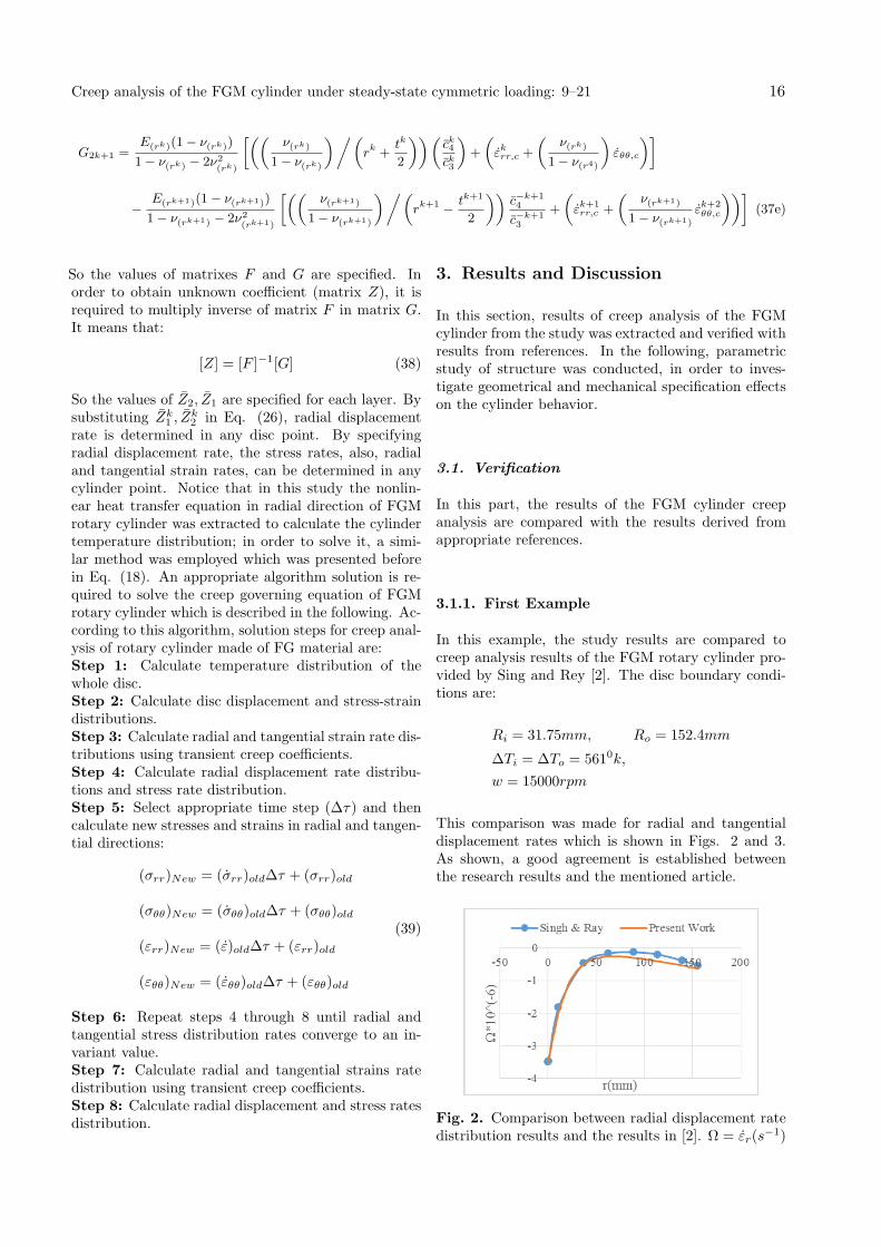
In this example, the study results are compared tocreep analysis results of the FGM rotary cylinder pro-vided by Sing and Rey [2]. The disc boundary condi-tions are:
Ri = 31.75mm, Ro = 152.4mm
∆Ti = ∆To = 5610k,
w = 15000rpm
This comparison was made for radial and tangentialdisplacement rates which is shown in Figs. 2 and 3.As shown, a good agreement is established betweenthe research results and the mentioned article.
Fig. 2. Comparison between radial displacement ratedistribution results and the results in [2]. Ω = εr(s
−1)
Creep analysis of the FGM cylinder under steady-state cymmetric loading: 9–21 16
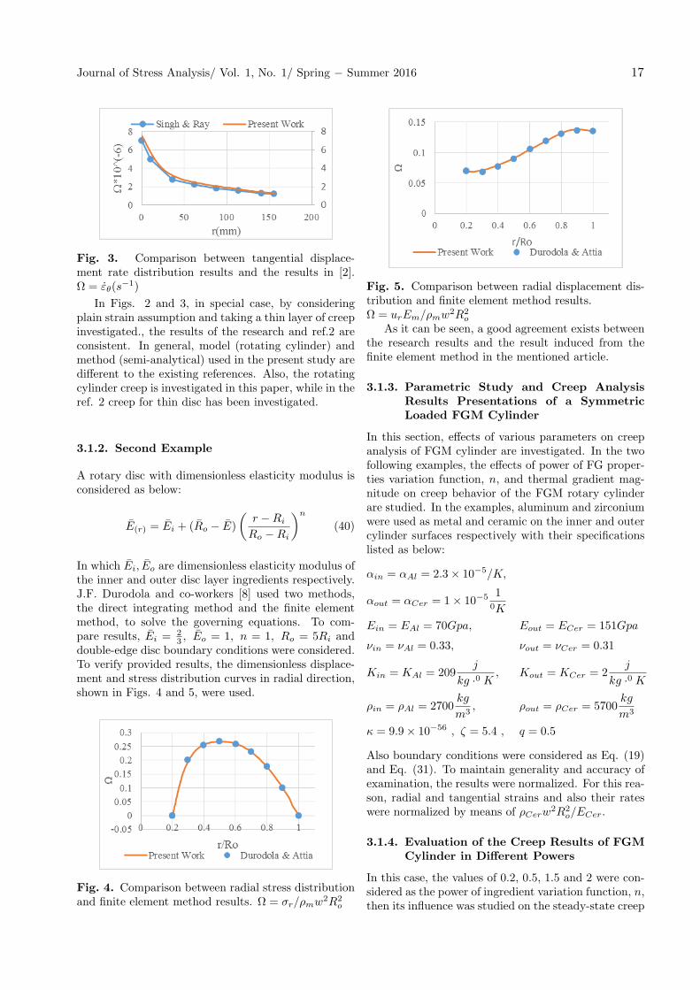
Fig. 3. Comparison between tangential displace-ment rate distribution results and the results in [2].Ω = εθ(s
−1)
In Figs. 2 and 3, in special case, by consideringplain strain assumption and taking a thin layer of creepinvestigated., the results of the research and ref.2 areconsistent. In general, model (rotating cylinder) andmethod (semi-analytical) used in the present study aredifferent to the existing references. Also, the rotatingcylinder creep is investigated in this paper, while in theref. 2 creep for thin disc has been investigated.
3.1.2. Second Example
A rotary disc with dimensionless elasticity modulus isconsidered as below:
E(r) = Ei + (Ro − E)
(r −Ri
Ro −Ri
)n
(40)
In which Ei, Eo are dimensionless elasticity modulus ofthe inner and outer disc layer ingredients respectively.J.F. Durodola and co-workers [8] used two methods,the direct integrating method and the finite elementmethod, to solve the governing equations. To com-pare results, Ei =
23 , Eo = 1, n = 1, Ro = 5Ri and
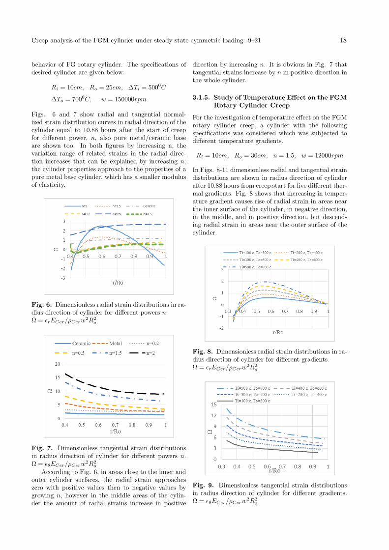
double-edge disc boundary conditions were considered.To verify provided results, the dimensionless displace-ment and stress distribution curves in radial direction,shown in Figs. 4 and 5, were used.
Fig. 4. Comparison between radial stress distributionand finite element method results. Ω = σr/ρmw2R2
o
Fig. 5. Comparison between radial displacement dis-tribution and finite element method results.Ω = urEm/ρmw2R2
o
As it can be seen, a good agreement exists betweenthe research results and the result induced from thefinite element method in the mentioned article.
3.1.3. Parametric Study and Creep AnalysisResults Presentations of a SymmetricLoaded FGM Cylinder
In this section, effects of various parameters on creepanalysis of FGM cylinder are investigated. In the twofollowing examples, the effects of power of FG proper-ties variation function, n, and thermal gradient mag-nitude on creep behavior of the FGM rotary cylinderare studied. In the examples, aluminum and zirconiumwere used as metal and ceramic on the inner and outercylinder surfaces respectively with their specificationslisted as below:
αin = αAl = 2.3× 10⁻⁵/K,
αout = αCer = 1× 10⁻⁵ 10K
Ein = EAl = 70Gpa, Eout = ECer = 151Gpa
νin = νAl = 0.33, νout = νCer = 0.31
Kin = KAl = 209j
kg ·0 K, Kout = KCer = 2
j
kg ·0 K
ρin = ρAl = 2700kg
m3, ρout = ρCer = 5700
kg
m3
κ = 9.9× 10−56 , ζ = 5.4 , q = 0.5
Also boundary conditions were considered as Eq. (19)and Eq. (31). To maintain generality and accuracy ofexamination, the results were normalized. For this rea-son, radial and tangential strains and also their rateswere normalized by means of ρCerw
2R2o/ECer.
3.1.4. Evaluation of the Creep Results of FGMCylinder in Different Powers
In this case, the values of 0.2, 0.5, 1.5 and 2 were con-sidered as the power of ingredient variation function, n,then its influence was studied on the steady-state creep
Journal of Stress Analysis/ Vol. 1, No. 1/ Spring − Summer 2016 17
behavior of FG rotary cylinder. The specifications ofdesired cylinder are given below:
Ri = 10cm, Ro = 25cm, ∆Ti = 5000C
∆To = 7000C, w = 150000rpm
Figs. 6 and 7 show radial and tangential normal-ized strain distribution curves in radial direction of thecylinder equal to 10.88 hours after the start of creepfor different power, n, also pure metal/ceramic baseare shown too. In both figures by increasing n, thevariation range of related strains in the radial direc-tion increases that can be explained by increasing n;the cylinder properties approach to the properties of apure metal base cylinder, which has a smaller modulusof elasticity.
Fig. 6. Dimensionless radial strain distributions in ra-dius direction of cylinder for different powers n.Ω = ϵrECer/ρCerw
2R2o
Fig. 7. Dimensionless tangential strain distributionsin radius direction of cylinder for different powers n.Ω = ϵθECer/ρCerw
2R2o
According to Fig. 6, in areas close to the inner andouter cylinder surfaces, the radial strain approacheszero with positive values then to negative values bygrowing n, however in the middle areas of the cylin-der the amount of radial strains increase in positive
direction by increasing n. It is obvious in Fig. 7 thattangential strains increase by n in positive direction inthe whole cylinder.
3.1.5. Study of Temperature Effect on the FGMRotary Cylinder Creep
For the investigation of temperature effect on the FGMrotary cylinder creep, a cylinder with the followingspecifications was considered which was subjected todifferent temperature gradients.
Ri = 10cm, Ro = 30cm, n = 1.5, w = 12000rpm
In Figs. 8-11 dimensionless radial and tangential straindistributions are shown in radius direction of cylinderafter 10.88 hours from creep start for five different ther-mal gradients. Fig. 8 shows that increasing in temper-ature gradient causes rise of radial strain in areas nearthe inner surface of the cylinder, in negative direction,in the middle, and in positive direction, but descend-ing radial strain in areas near the outer surface of thecylinder.
Fig. 8. Dimensionless radial strain distributions in ra-dius direction of cylinder for different gradients.Ω = ϵrECer/ρCerw
2R2o
Fig. 9. Dimensionless tangential strain distributionsin radius direction of cylinder for different gradients.Ω = ϵθECer/ρCerw
2R2o
Creep analysis of the FGM cylinder under steady-state cymmetric loading: 9–21 18
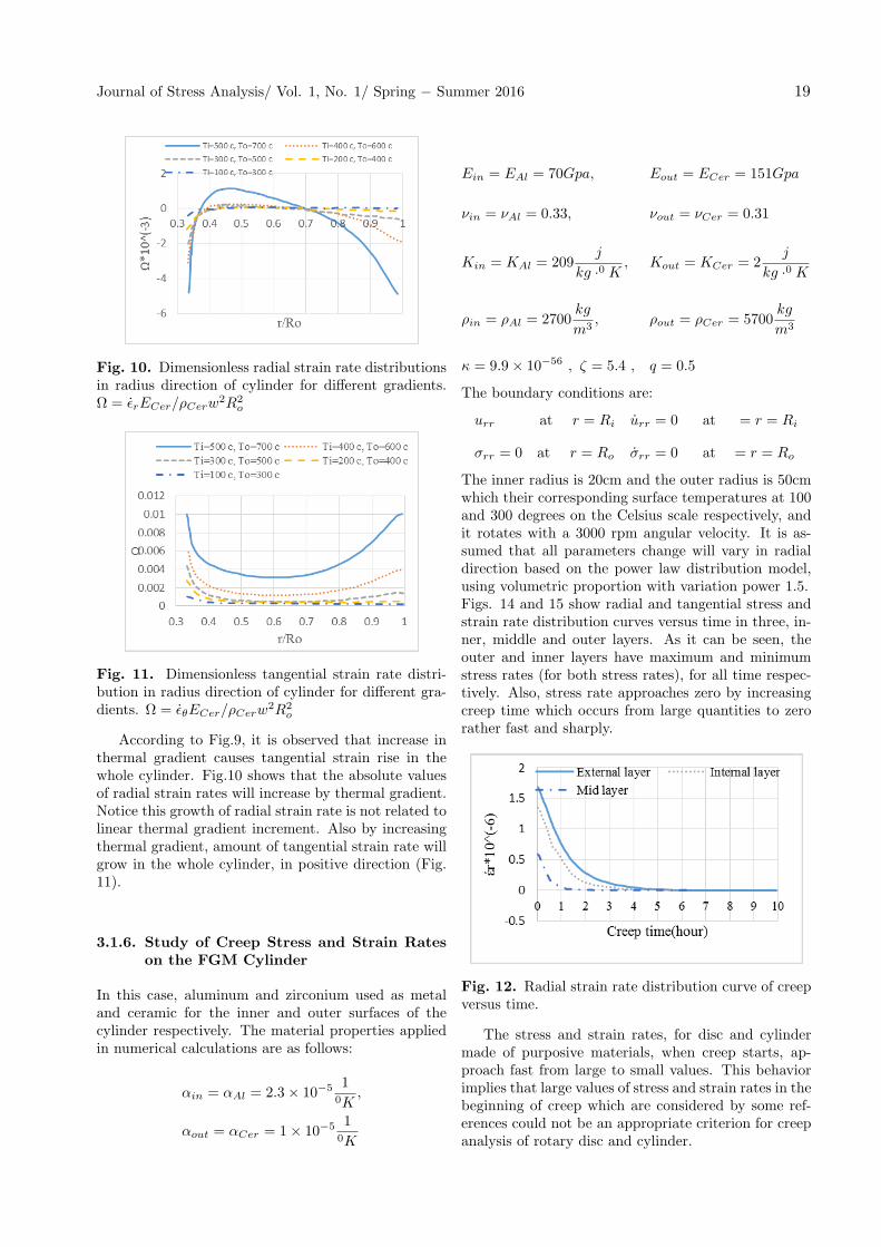
Fig. 10. Dimensionless radial strain rate distributionsin radius direction of cylinder for different gradients.Ω = ϵrECer/ρCerw
2R2o
Fig. 11. Dimensionless tangential strain rate distri-bution in radius direction of cylinder for different gra-dients. Ω = ϵθECer/ρCerw
2R2o
According to Fig.9, it is observed that increase inthermal gradient causes tangential strain rise in thewhole cylinder. Fig.10 shows that the absolute valuesof radial strain rates will increase by thermal gradient.Notice this growth of radial strain rate is not related tolinear thermal gradient increment. Also by increasingthermal gradient, amount of tangential strain rate willgrow in the whole cylinder, in positive direction (Fig.11).
3.1.6. Study of Creep Stress and Strain Rateson the FGM Cylinder
In this case, aluminum and zirconium used as metaland ceramic for the inner and outer surfaces of thecylinder respectively. The material properties appliedin numerical calculations are as follows:
αin = αAl = 2.3× 10⁻⁵ 10K
,
αout = αCer = 1× 10⁻⁵ 10K
Ein = EAl = 70Gpa, Eout = ECer = 151Gpa
νin = νAl = 0.33, νout = νCer = 0.31
Kin = KAl = 209j
kg ·0 K, Kout = KCer = 2
j
kg ·0 K
ρin = ρAl = 2700kg
m3, ρout = ρCer = 5700
kg
m3
κ = 9.9× 10−56 , ζ = 5.4 , q = 0.5
The boundary conditions are:
urr at r = Ri urr = 0 at = r = Ri
σrr = 0 at r = Ro σrr = 0 at = r = Ro
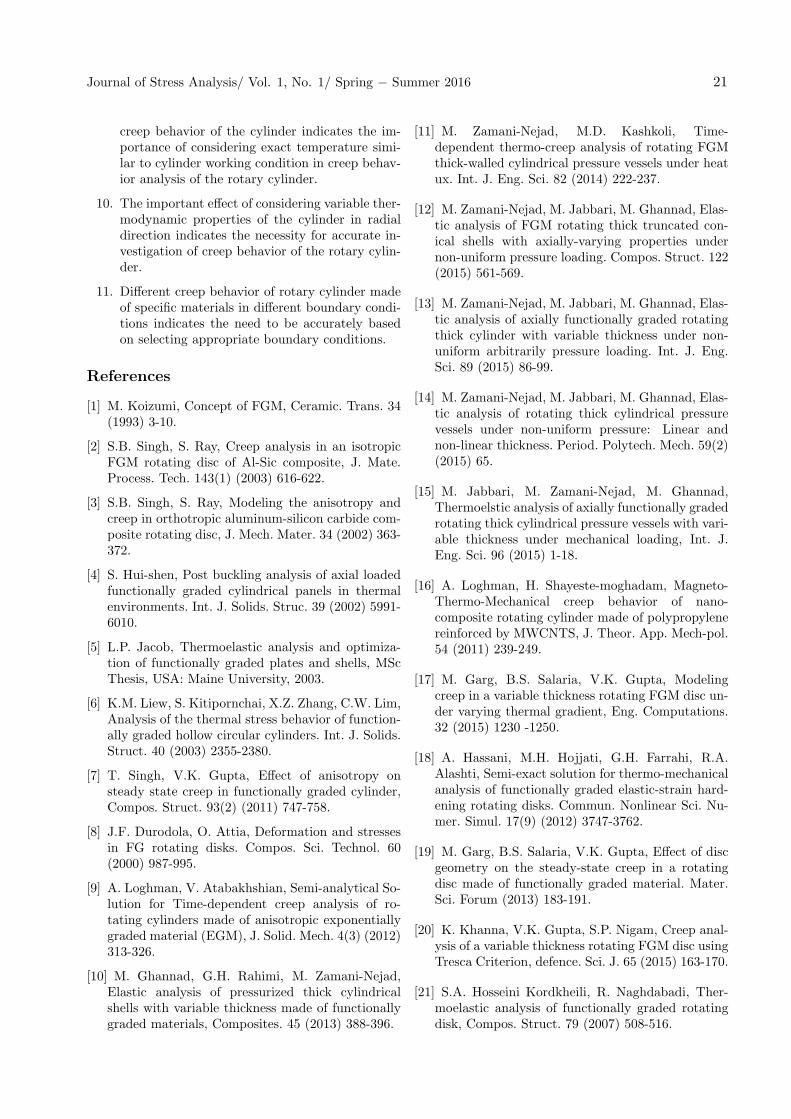
The inner radius is 20cm and the outer radius is 50cmwhich their corresponding surface temperatures at 100and 300 degrees on the Celsius scale respectively, andit rotates with a 3000 rpm angular velocity. It is as-sumed that all parameters change will vary in radialdirection based on the power law distribution model,using volumetric proportion with variation power 1.5.Figs. 14 and 15 show radial and tangential stress andstrain rate distribution curves versus time in three, in-ner, middle and outer layers. As it can be seen, theouter and inner layers have maximum and minimumstress rates (for both stress rates), for all time respec-tively. Also, stress rate approaches zero by increasingcreep time which occurs from large quantities to zerorather fast and sharply.
Fig. 12. Radial strain rate distribution curve of creepversus time.
The stress and strain rates, for disc and cylindermade of purposive materials, when creep starts, ap-proach fast from large to small values. This behaviorimplies that large values of stress and strain rates in thebeginning of creep which are considered by some ref-erences could not be an appropriate criterion for creepanalysis of rotary disc and cylinder.
Journal of Stress Analysis/ Vol. 1, No. 1/ Spring − Summer 2016 19
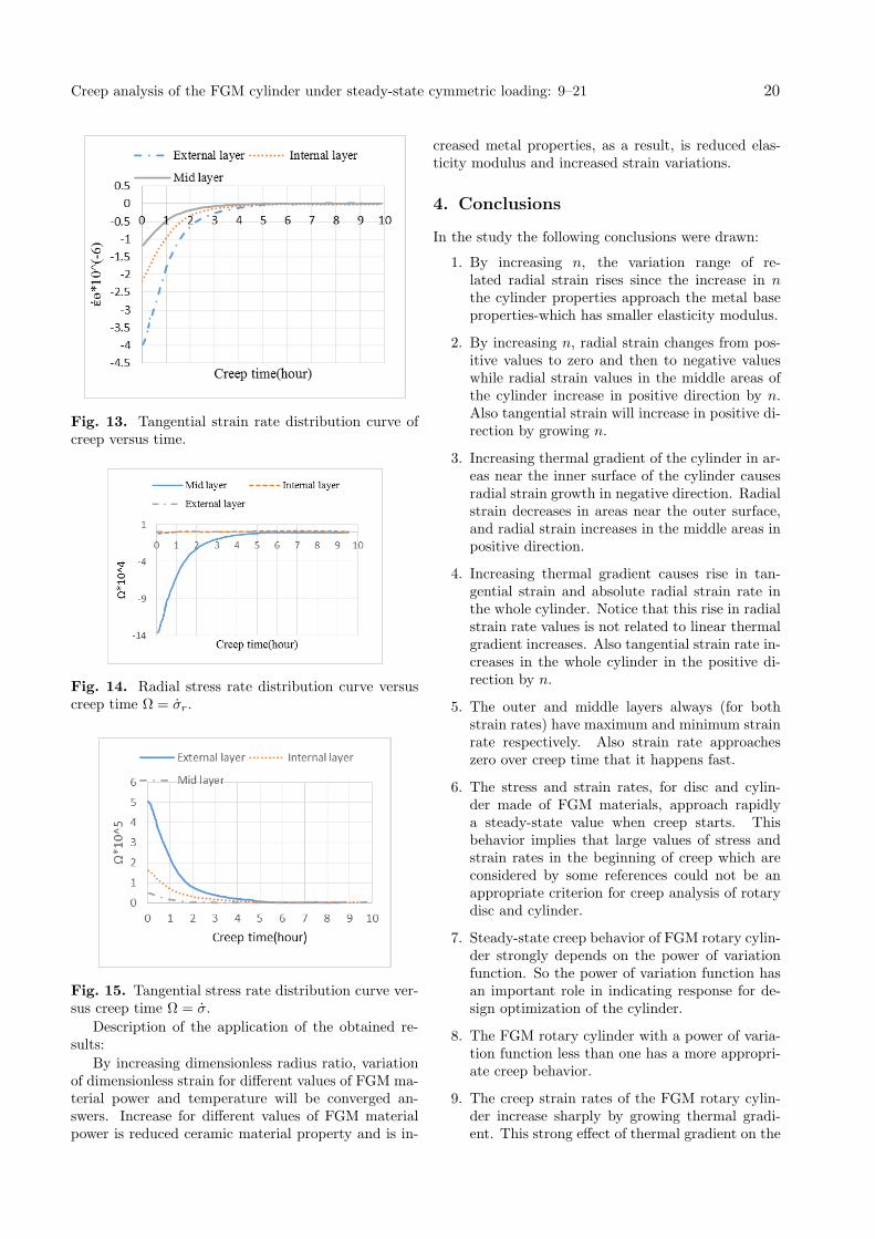
Fig. 13. Tangential strain rate distribution curve ofcreep versus time.
Fig. 14. Radial stress rate distribution curve versuscreep time Ω = σr.
Fig. 15. Tangential stress rate distribution curve ver-sus creep time Ω = σ.
Description of the application of the obtained re-sults:
By increasing dimensionless radius ratio, variationof dimensionless strain for different values of FGM ma-terial power and temperature will be converged an-swers. Increase for different values of FGM materialpower is reduced ceramic material property and is in-
creased metal properties, as a result, is reduced elas-ticity modulus and increased strain variations.
4. Conclusions
In the study the following conclusions were drawn:
1. By increasing n, the variation range of re-lated radial strain rises since the increase in nthe cylinder properties approach the metal baseproperties-which has smaller elasticity modulus.
2. By increasing n, radial strain changes from pos-itive values to zero and then to negative valueswhile radial strain values in the middle areas ofthe cylinder increase in positive direction by n.Also tangential strain will increase in positive di-rection by growing n.
3. Increasing thermal gradient of the cylinder in ar-eas near the inner surface of the cylinder causesradial strain growth in negative direction. Radialstrain decreases in areas near the outer surface,and radial strain increases in the middle areas inpositive direction.
4. Increasing thermal gradient causes rise in tan-gential strain and absolute radial strain rate inthe whole cylinder. Notice that this rise in radialstrain rate values is not related to linear thermalgradient increases. Also tangential strain rate in-creases in the whole cylinder in the positive di-rection by n.
5. The outer and middle layers always (for bothstrain rates) have maximum and minimum strainrate respectively. Also strain rate approacheszero over creep time that it happens fast.
6. The stress and strain rates, for disc and cylin-der made of FGM materials, approach rapidlya steady-state value when creep starts. Thisbehavior implies that large values of stress andstrain rates in the beginning of creep which areconsidered by some references could not be anappropriate criterion for creep analysis of rotarydisc and cylinder.
7. Steady-state creep behavior of FGM rotary cylin-der strongly depends on the power of variationfunction. So the power of variation function hasan important role in indicating response for de-sign optimization of the cylinder.
8. The FGM rotary cylinder with a power of varia-tion function less than one has a more appropri-ate creep behavior.
9. The creep strain rates of the FGM rotary cylin-der increase sharply by growing thermal gradi-ent. This strong effect of thermal gradient on the
Creep analysis of the FGM cylinder under steady-state cymmetric loading: 9–21 20
creep behavior of the cylinder indicates the im-portance of considering exact temperature simi-lar to cylinder working condition in creep behav-ior analysis of the rotary cylinder.
10. The important effect of considering variable ther-modynamic properties of the cylinder in radialdirection indicates the necessity for accurate in-vestigation of creep behavior of the rotary cylin-der.
11. Different creep behavior of rotary cylinder madeof specific materials in different boundary condi-tions indicates the need to be accurately basedon selecting appropriate boundary conditions.
References
[1] M. Koizumi, Concept of FGM, Ceramic. Trans. 34(1993) 3-10.
[2] S.B. Singh, S. Ray, Creep analysis in an isotropicFGM rotating disc of Al-Sic composite, J. Mate.Process. Tech. 143(1) (2003) 616-622.
[3] S.B. Singh, S. Ray, Modeling the anisotropy andcreep in orthotropic aluminum-silicon carbide com-posite rotating disc, J. Mech. Mater. 34 (2002) 363-372.
[4] S. Hui-shen, Post buckling analysis of axial loadedfunctionally graded cylindrical panels in thermalenvironments. Int. J. Solids. Struc. 39 (2002) 5991-6010.
[5] L.P. Jacob, Thermoelastic analysis and optimiza-tion of functionally graded plates and shells, MScThesis, USA: Maine University, 2003.
[6] K.M. Liew, S. Kitipornchai, X.Z. Zhang, C.W. Lim,Analysis of the thermal stress behavior of function-ally graded hollow circular cylinders. Int. J. Solids.Struct. 40 (2003) 2355-2380.
[7] T. Singh, V.K. Gupta, Effect of anisotropy onsteady state creep in functionally graded cylinder,Compos. Struct. 93(2) (2011) 747-758.
[8] J.F. Durodola, O. Attia, Deformation and stressesin FG rotating disks. Compos. Sci. Technol. 60(2000) 987-995.
[9] A. Loghman, V. Atabakhshian, Semi-analytical So-lution for Time-dependent creep analysis of ro-tating cylinders made of anisotropic exponentiallygraded material (EGM), J. Solid. Mech. 4(3) (2012)313-326.
[10] M. Ghannad, G.H. Rahimi, M. Zamani-Nejad,Elastic analysis of pressurized thick cylindricalshells with variable thickness made of functionallygraded materials, Composites. 45 (2013) 388-396.
[11] M. Zamani-Nejad, M.D. Kashkoli, Time-dependent thermo-creep analysis of rotating FGMthick-walled cylindrical pressure vessels under heatux. Int. J. Eng. Sci. 82 (2014) 222-237.
[12] M. Zamani-Nejad, M. Jabbari, M. Ghannad, Elas-tic analysis of FGM rotating thick truncated con-ical shells with axially-varying properties undernon-uniform pressure loading. Compos. Struct. 122(2015) 561-569.
[13] M. Zamani-Nejad, M. Jabbari, M. Ghannad, Elas-tic analysis of axially functionally graded rotatingthick cylinder with variable thickness under non-uniform arbitrarily pressure loading. Int. J. Eng.Sci. 89 (2015) 86-99.
[14] M. Zamani-Nejad, M. Jabbari, M. Ghannad, Elas-tic analysis of rotating thick cylindrical pressurevessels under non-uniform pressure: Linear andnon-linear thickness. Period. Polytech. Mech. 59(2)(2015) 65.
[15] M. Jabbari, M. Zamani-Nejad, M. Ghannad,Thermoelstic analysis of axially functionally gradedrotating thick cylindrical pressure vessels with vari-able thickness under mechanical loading, Int. J.Eng. Sci. 96 (2015) 1-18.
[16] A. Loghman, H. Shayeste-moghadam, Magneto-Thermo-Mechanical creep behavior of nano-composite rotating cylinder made of polypropylenereinforced by MWCNTS, J. Theor. App. Mech-pol.54 (2011) 239-249.
[17] M. Garg, B.S. Salaria, V.K. Gupta, Modelingcreep in a variable thickness rotating FGM disc un-der varying thermal gradient, Eng. Computations.32 (2015) 1230 -1250.
[18] A. Hassani, M.H. Hojjati, G.H. Farrahi, R.A.Alashti, Semi-exact solution for thermo-mechanicalanalysis of functionally graded elastic-strain hard-ening rotating disks. Commun. Nonlinear Sci. Nu-mer. Simul. 17(9) (2012) 3747-3762.
[19] M. Garg, B.S. Salaria, V.K. Gupta, Effect of discgeometry on the steady-state creep in a rotatingdisc made of functionally graded material. Mater.Sci. Forum (2013) 183-191.
[20] K. Khanna, V.K. Gupta, S.P. Nigam, Creep anal-ysis of a variable thickness rotating FGM disc usingTresca Criterion, defence. Sci. J. 65 (2015) 163-170.
[21] S.A. Hosseini Kordkheili, R. Naghdabadi, Ther-moelastic analysis of functionally graded rotatingdisk, Compos. Struct. 79 (2007) 508-516.
Journal of Stress Analysis/ Vol. 1, No. 1/ Spring − Summer 2016 21


![Mechanical Stresses in a Linear Plastic FGM Hollow ...journals.iau.ir/article_527016_0d08eef07a5802a42c17e525cb2c8a3e.pdfloads. Lu yunbing et al. [5] analyzed the steady state temperature](https://img.pdfslide.net/doc/110x75/60ae0cbbc79be86dbc1674c6/mechanical-stresses-in-a-linear-plastic-fgm-hollow-loads-lu-yunbing-et-al.jpg)


![Asymmetric Thermal Stresses of Hollow FGM Cylinders with ... · quadrature method. Heyliger [29] carried out an exact three-dimensional analysis of a laminated piezoelectric cylinder](https://img.pdfslide.net/doc/110x75/5e3e4cfdf852441cc11f3b1a/asymmetric-thermal-stresses-of-hollow-fgm-cylinders-with-quadrature-method.jpg)