Embed Size (px)
Citation preview
Creep-Fatigue-Oxidation Interactions:Predicting Alloy Lifetimes under Fossil
Energy Service Conditions
Sebastien Dryepondt
Amit Shyam
Oak Ridge National Laboratory
2015 NETL Crosscutting Research Review Meeting
April 27-30 2015, Pittsburgh
2
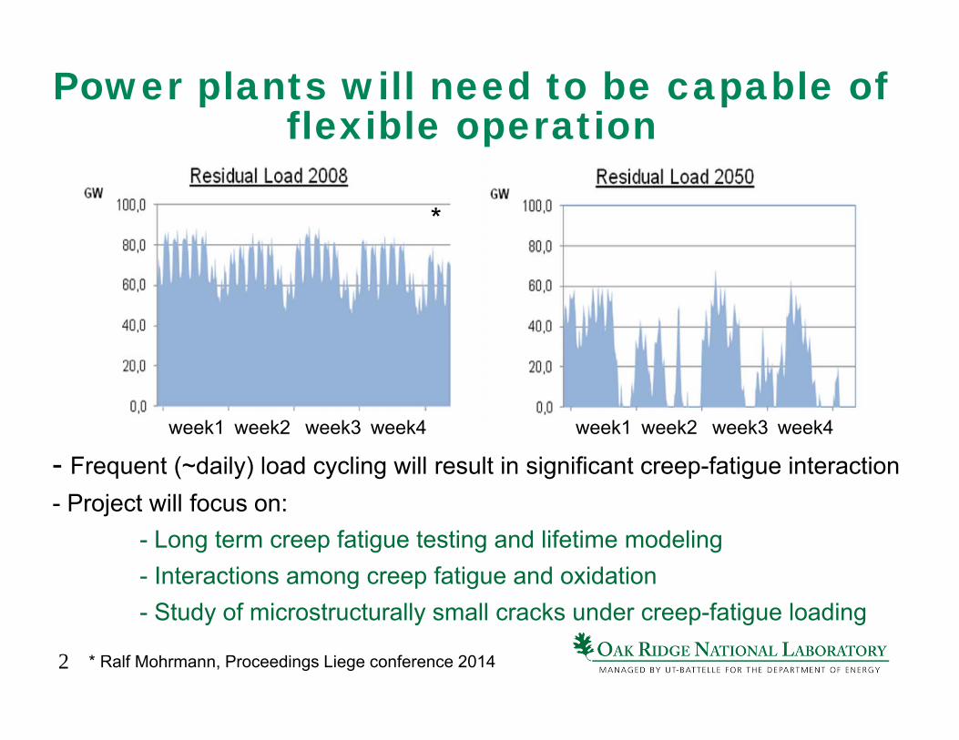
Power plants will need to be capable of flexible operation
- Frequent (~daily) load cycling will result in significant creep-fatigue interaction- Project will focus on:
- Long term creep fatigue testing and lifetime modeling- Interactions among creep fatigue and oxidation- Study of microstructurally small cracks under creep-fatigue loading
week1 week2 week3 week4 week1 week2 week3 week4
* Ralf Mohrmann, Proceedings Liege conference 2014
*
3
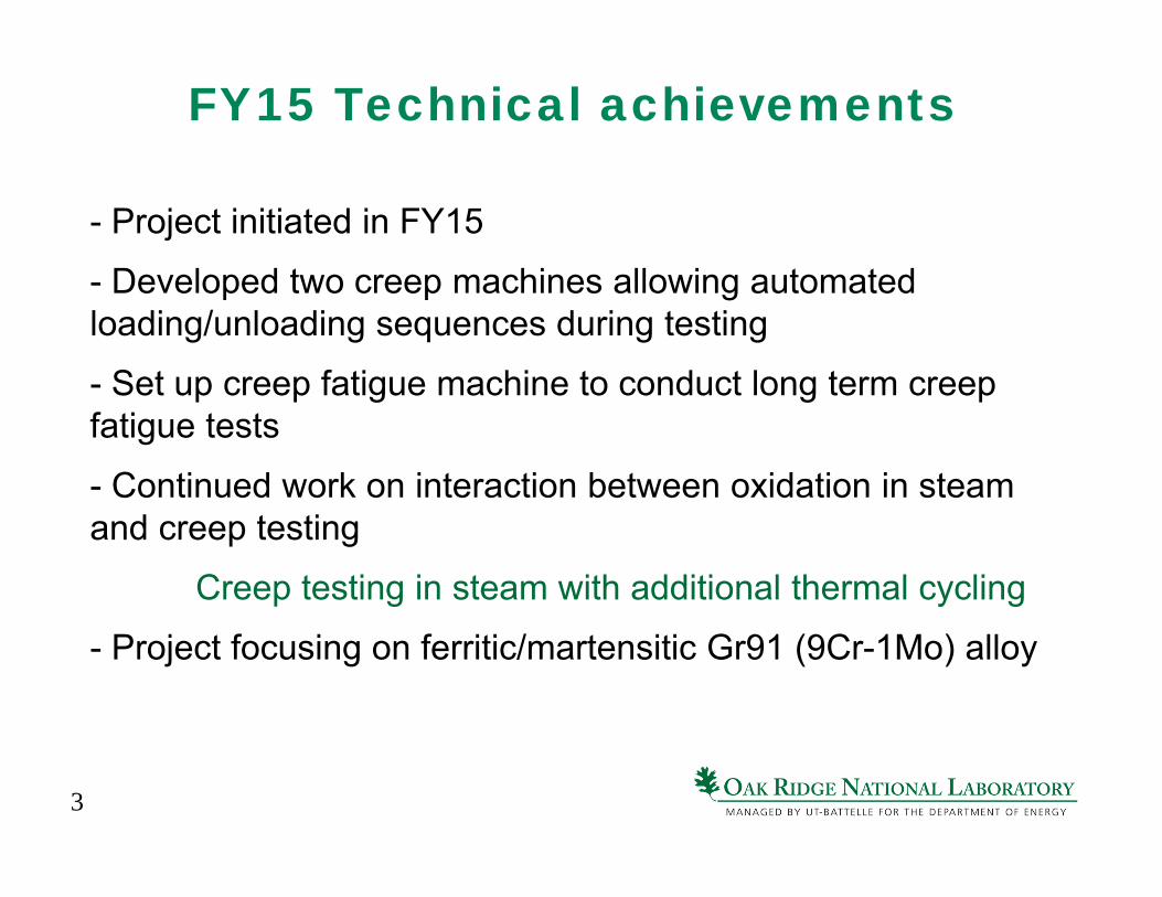
FY15 Technical achievements
- Project initiated in FY15
- Developed two creep machines allowing automated loading/unloading sequences during testing
- Set up creep fatigue machine to conduct long term creep fatigue tests
- Continued work on interaction between oxidation in steam and creep testing
Creep testing in steam with additional thermal cycling
- Project focusing on ferritic/martensitic Gr91 (9Cr-1Mo) alloy
4
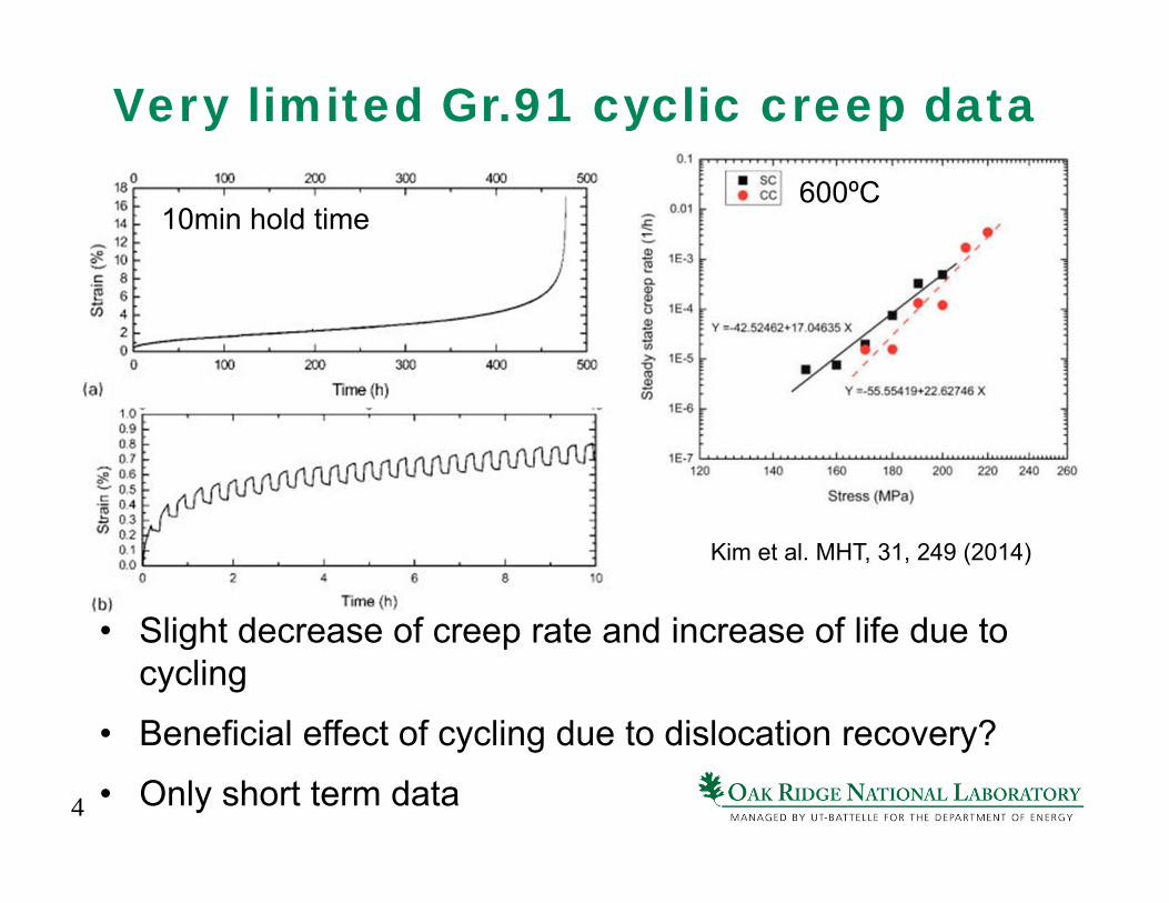
Very limited Gr.91 cyclic creep data
• Slight decrease of creep rate and increase of life due to cycling
• Beneficial effect of cycling due to dislocation recovery?
• Only short term data
Kim et al. MHT, 31, 249 (2014)
600ºC10min hold time
5
0
0.5
1
1.5
2
2.5
3
0 500 1000 1500
Strain
(%)
Time (h)
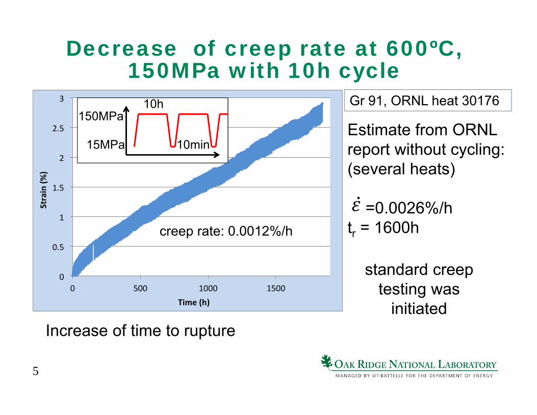
Decrease of creep rate at 600ºC, 150MPa with 10h cycle
creep rate: 0.0012%/h
Estimate from ORNL report without cycling:(several heats)
=0.0026%/htr = 1600h
standard creep testing was
initiated Increase of time to rupture
15MPa
150MPa10h
10min
Gr 91, ORNL heat 30176
6
0
40
80
120
160
1.9
2
2.1
2.2
2.3
1344 1344.5 1345 1345.5 1346
Stress
(MPa
)
Strain
(%)
Time (h)
0.3
0.4
0.5
0.6
0.7
203 203.5 204 204.5 205
Strain
(%)
Time (h)
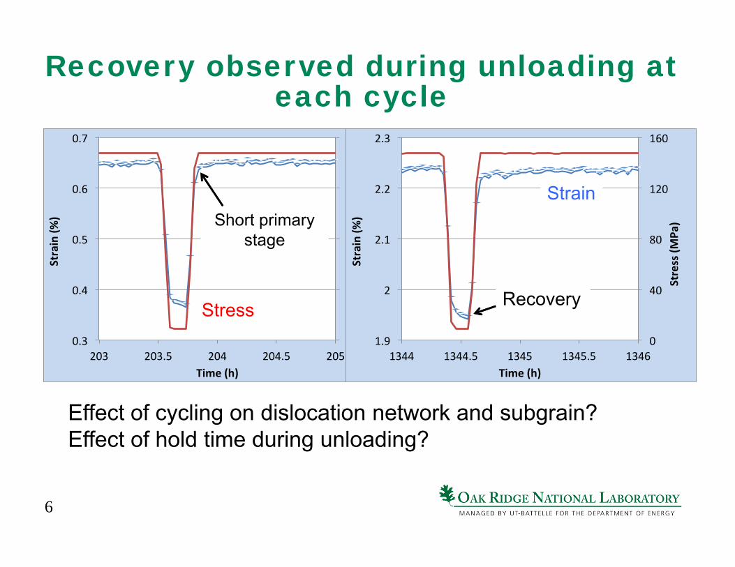
Recovery observed during unloading at each cycle
Recovery
Effect of cycling on dislocation network and subgrain?Effect of hold time during unloading?
Short primary stage
Stress
Strain
7
0
2
4
6
8
10
12
14
0 200 400 600 800 1000
Strain
(%)
Time (h)
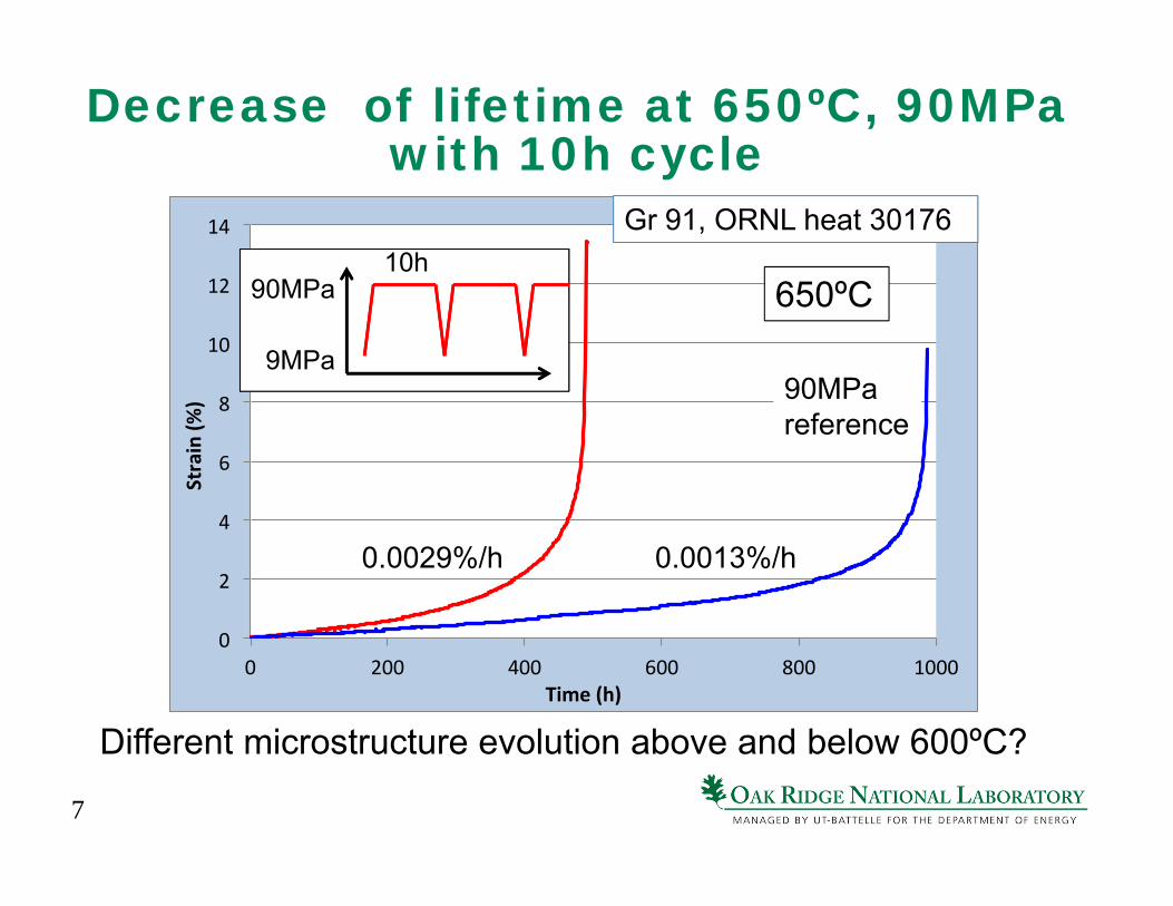
Decrease of lifetime at 650ºC, 90MPa with 10h cycle
650ºC
Gr 91, ORNL heat 30176
0.0013%/h0.0029%/h
90MPa reference
9MPa
90MPa10h
Different microstructure evolution above and below 600ºC?
8
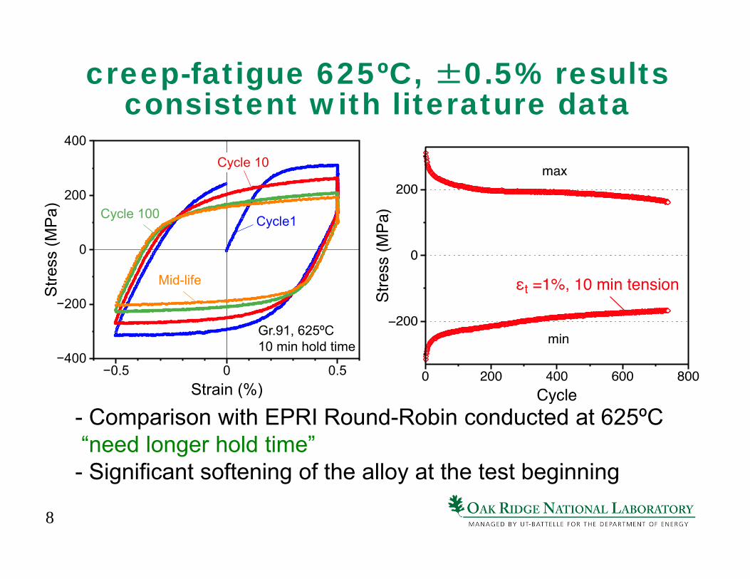
creep-fatigue 625ºC, ±0.5% results consistent with literature data
- Comparison with EPRI Round-Robin conducted at 625ºC“need longer hold time”- Significant softening of the alloy at the test beginning
Cycle 10
Cycle1Cycle 100
Mid-life
Gr.91, 625ºC10 min hold time
Stre
ss (M
Pa)
−400
−200
0
200
400
Strain (%)−0.5 0 0.5
9
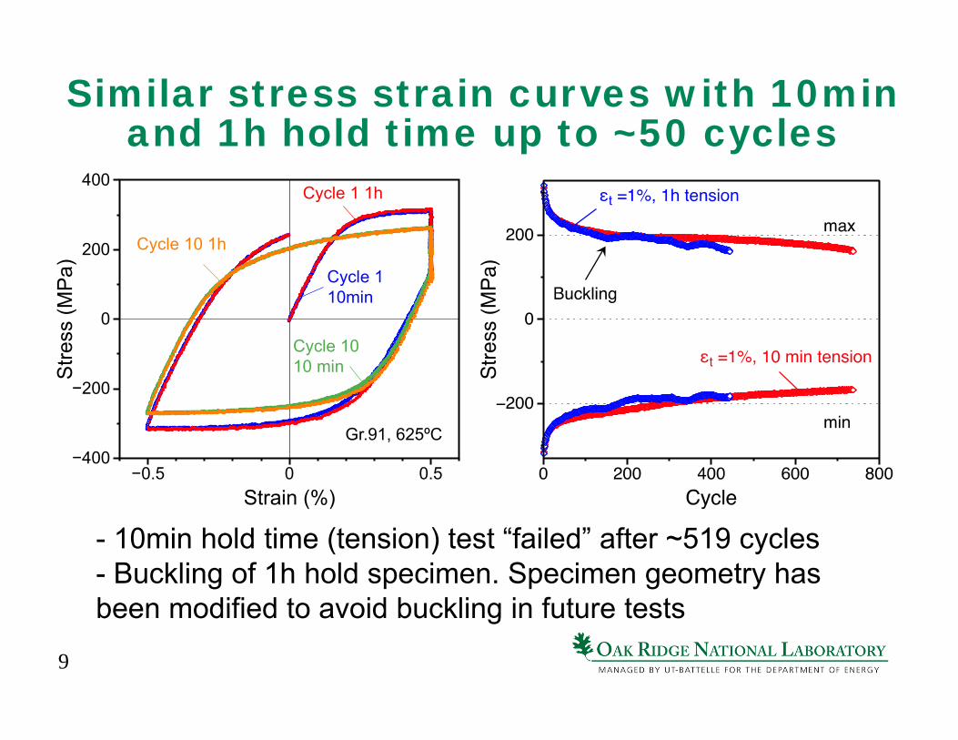
Similar stress strain curves with 10min and 1h hold time up to ~50 cycles
- 10min hold time (tension) test “failed” after ~519 cycles- Buckling of 1h hold specimen. Specimen geometry has been modified to avoid buckling in future tests
Cycle 1 1h
Cycle 1 10min
Cycle 1010 min
Gr.91, 625ºC
Cycle 10 1h
Stre
ss (M
Pa)
−400
−200
0
200
400
Strain (%)−0.5 0 0.5
10
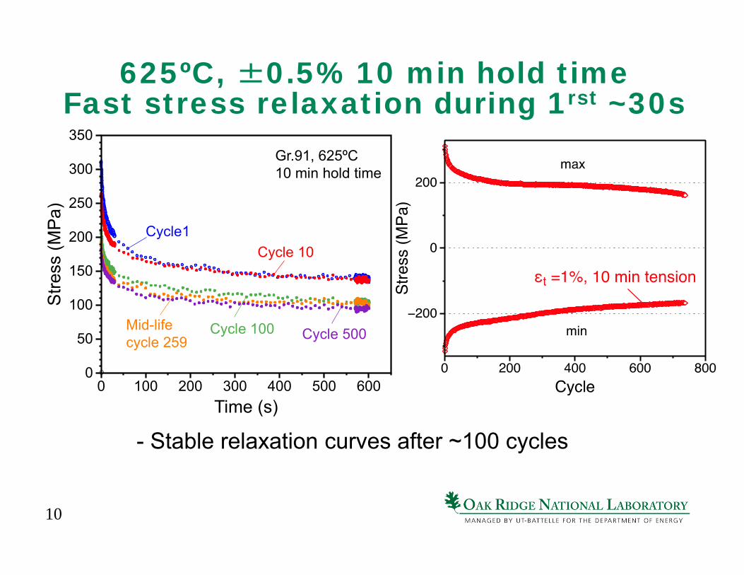
625ºC, ±0.5% 10 min hold time Fast stress relaxation during 1rst ~30s
- Stable relaxation curves after ~100 cycles
Cycle 10Cycle1
Cycle 100Mid-lifecycle 259
Gr.91, 625ºC10 min hold time
Cycle 500
Stre
ss (M
Pa)
0
50
100
150
200
250
300
350
Time (s)0 100 200 300 400 500 600
11
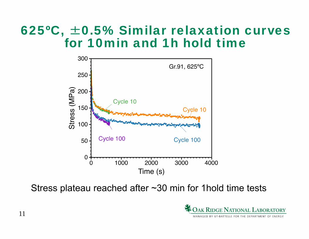
625ºC, ±0.5% Similar relaxation curves for 10min and 1h hold time
Stress plateau reached after ~30 min for 1hold time tests
12
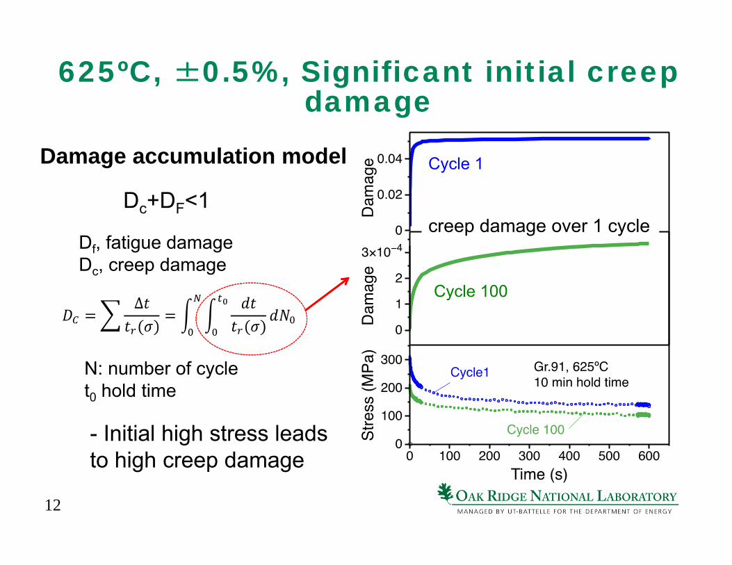
625ºC, ±0.5%, Significant initial creep damage
- Initial high stress leads to high creep damage
N: number of cyclet0 hold time
Damage accumulation model
Df, fatigue damage Dc, creep damage
creep damage over 1 cycle
Cycle 1
Cycle 100
Dc+DF<1
13
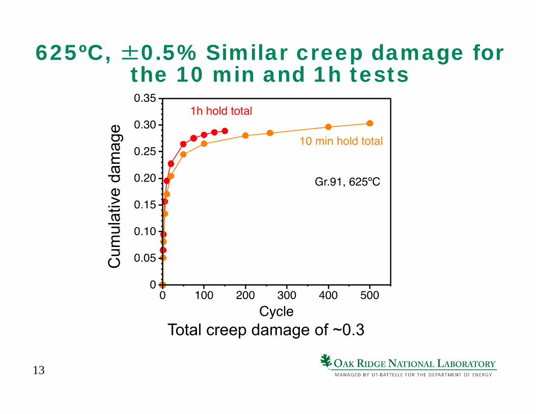
625ºC, ±0.5% Similar creep damage for the 10 min and 1h tests
Total creep damage of ~0.3
Cum
ulat
ive
dam
age
14
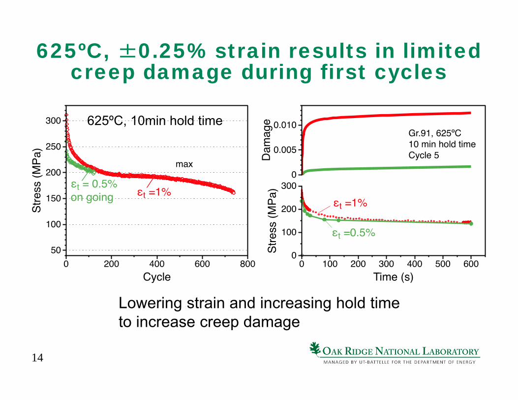
625ºC, ±0.25% strain results in limited creep damage during first cycles
Lowering strain and increasing hold time to increase creep damage
625ºC, 10min hold time
15
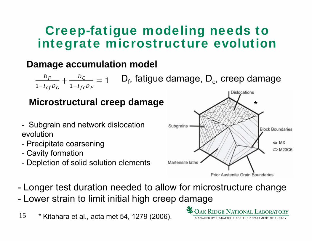
Creep-fatigue modeling needs to integrate microstructure evolution
Damage accumulation modelDf, fatigue damage, Dc, creep damage
- Longer test duration needed to allow for microstructure change- Lower strain to limit initial high creep damage
- Subgrain and network dislocation evolution- Precipitate coarsening- Cavity formation- Depletion of solid solution elements
Microstructural creep damage
* Kitahara et al., acta met 54, 1279 (2006).
*
16
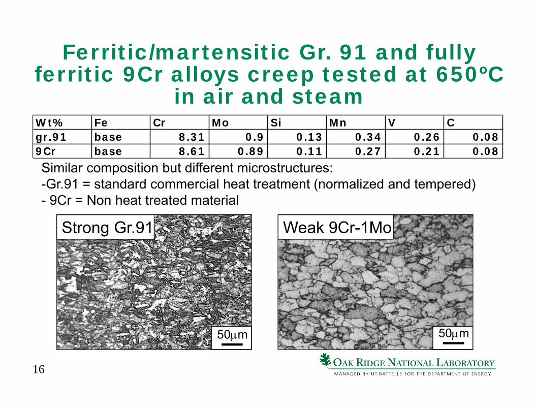
Ferritic/martensitic Gr. 91 and fully ferritic 9Cr alloys creep tested at 650ºC
in air and steam
Similar composition but different microstructures:-Gr.91 = standard commercial heat treatment (normalized and tempered)- 9Cr = Non heat treated material
Wt% Fe Cr Mo Si Mn V Cgr.91 base 8.31 0.9 0.13 0.34 0.26 0.089Cr base 8.61 0.89 0.11 0.27 0.21 0.08
50m50m
Strong Gr.91 Weak 9Cr-1Mo
17
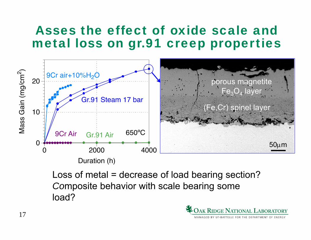
Asses the effect of oxide scale and metal loss on gr.91 creep properties
Loss of metal = decrease of load bearing section?Composite behavior with scale bearing some load?
porous magnetite Fe3O4 layer
(Fe,Cr) spinel layer
50m
18
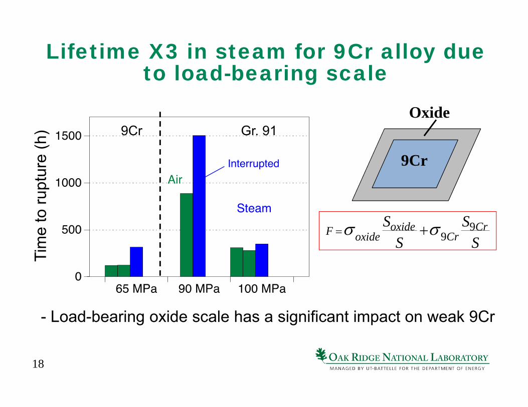
Lifetime X3 in steam for 9Cr alloy due to load-bearing scale
- Load-bearing oxide scale has a significant impact on weak 9Cr
Tim
e to
rupt
ure
(h)
9Cr
Oxide
F oxideSoxide
S 9Cr
S9CrS
9Cr Gr. 91
19
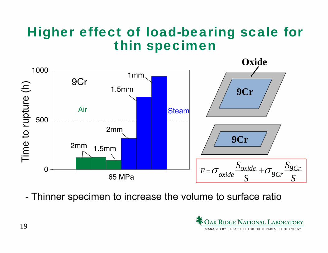
Higher effect of load-bearing scale for thin specimen
- Thinner specimen to increase the volume to surface ratio
Tim
e to
rupt
ure
(h)
9Cr
Oxide
F oxideSoxide
S 9Cr
S9CrS
9Cr
20
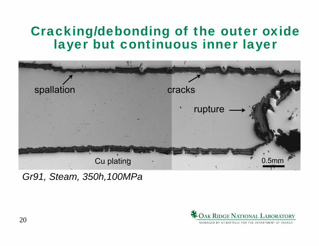
Cracking/debonding of the outer oxide layer but continuous inner layer
0.5mm
rupture
Cu plating
Gr91, Steam, 350h,100MPa
spallation cracks
21
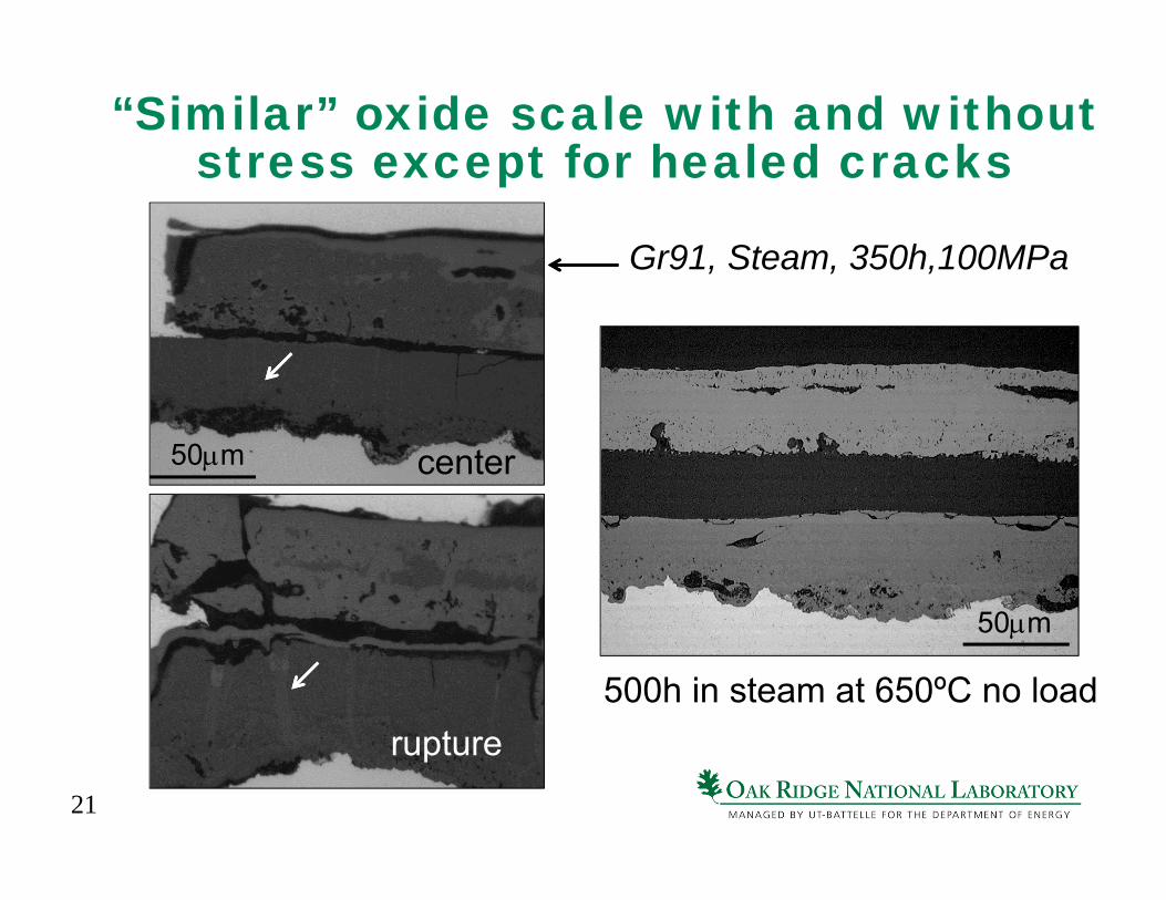
“Similar” oxide scale with and without stress except for healed cracks
500h in steam at 650ºC no load
50m
Gr91, Steam, 350h,100MPa
50m center
rupture
22
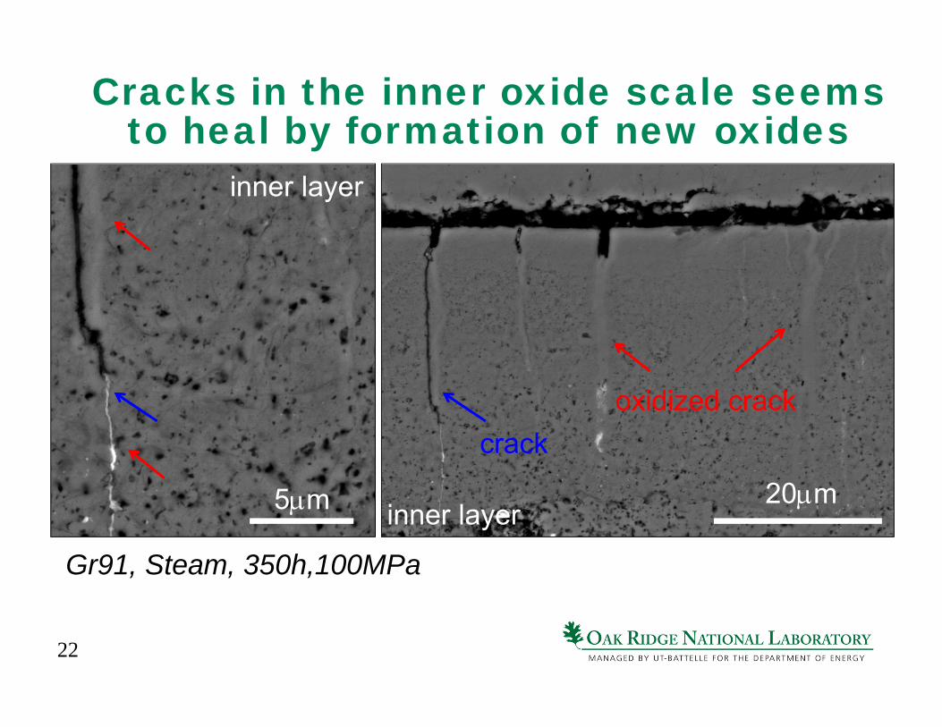
Cracks in the inner oxide scale seems to heal by formation of new oxides
20m
oxidized crackcrack
Gr91, Steam, 350h,100MPa
5m
inner layer
inner layer
23
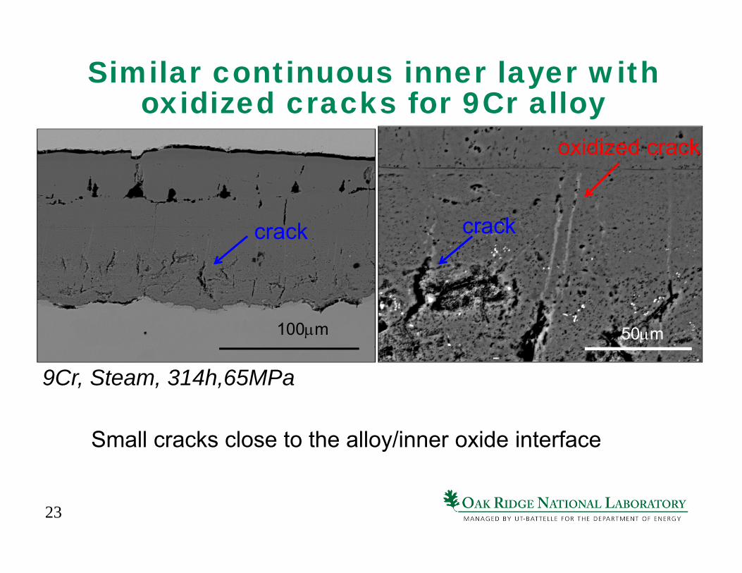
Similar continuous inner layer with oxidized cracks for 9Cr alloy
Small cracks close to the alloy/inner oxide interface
100m 50m
9Cr, Steam, 314h,65MPa
oxidized crack
crack crack
24
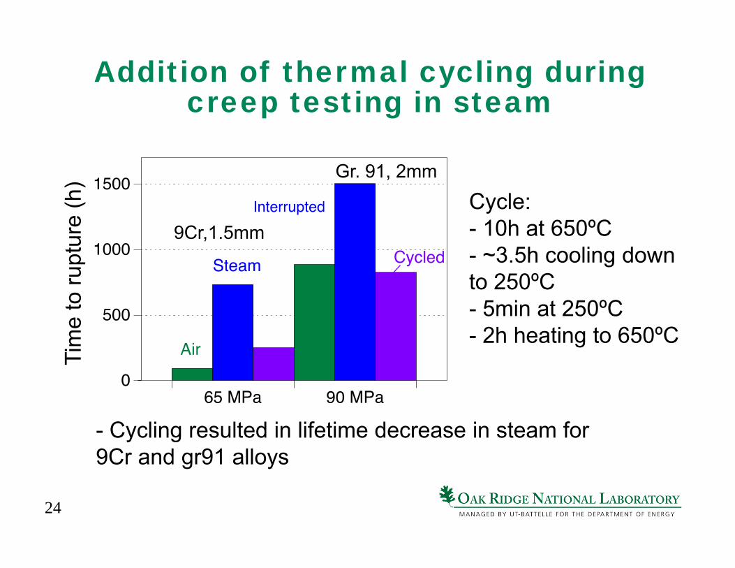
Addition of thermal cycling during creep testing in steam
- Cycling resulted in lifetime decrease in steam for 9Cr and gr91 alloys
Tim
e to
rupt
ure
(h)
9Cr,1.5mm
Gr. 91, 2mm
Cycle: - 10h at 650ºC- ~3.5h cooling down to 250ºC - 5min at 250ºC - 2h heating to 650ºC
25
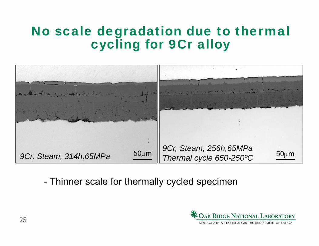
No scale degradation due to thermal cycling for 9Cr alloy
- Thinner scale for thermally cycled specimen
9Cr, Steam, 314h,65MPa 9Cr, Steam, 256h,65MPaThermal cycle 650-250ºC 50m 50m
26
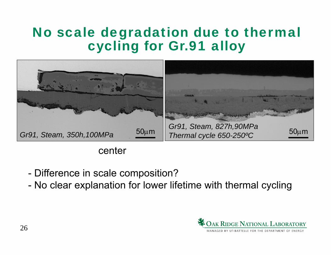
No scale degradation due to thermal cycling for Gr.91 alloy
- Difference in scale composition?- No clear explanation for lower lifetime with thermal cycling
Gr91, Steam, 827h,90MPaThermal cycle 650-250ºC 50m
center
50mGr91, Steam, 350h,100MPa
27
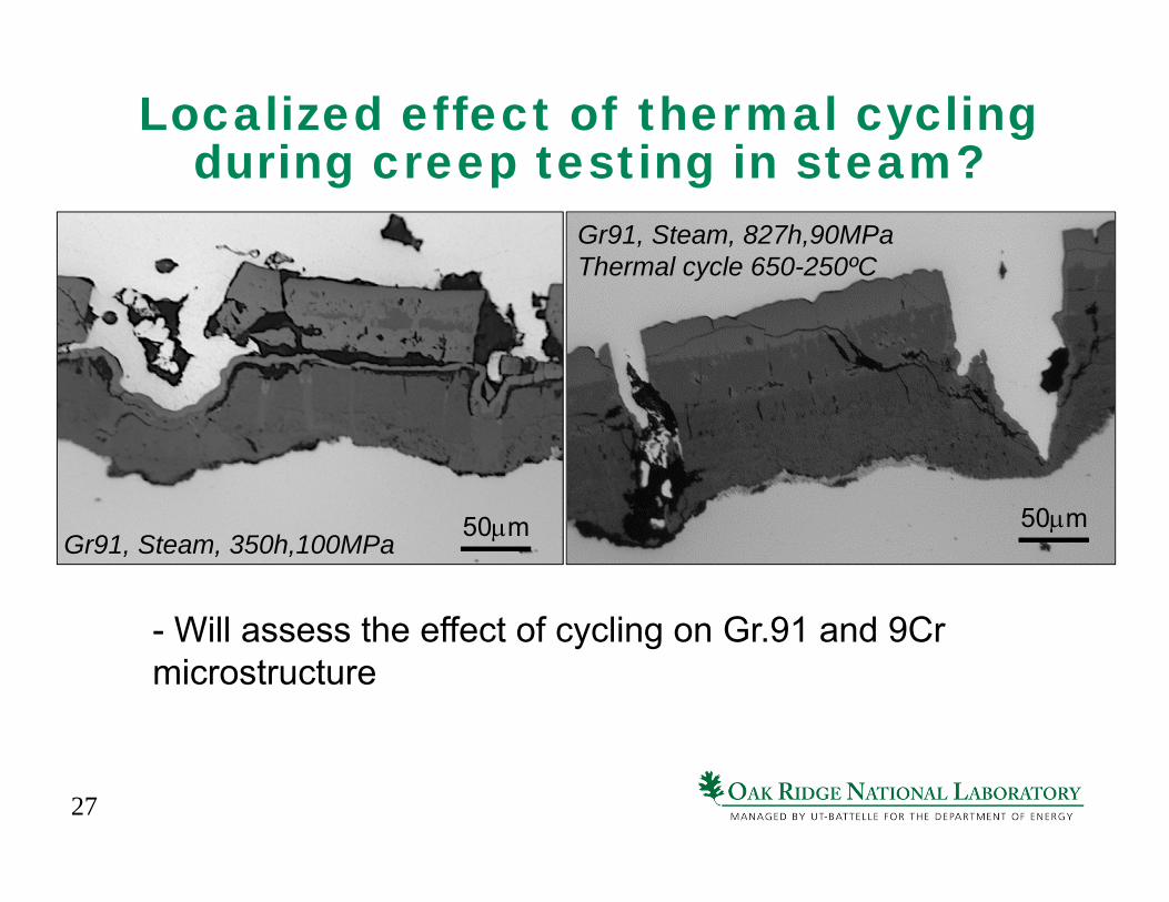
Localized effect of thermal cycling during creep testing in steam?
- Will assess the effect of cycling on Gr.91 and 9Cr microstructure
50m center50m
Gr91, Steam, 350h,100MPa
Gr91, Steam, 827h,90MPaThermal cycle 650-250ºC
50m
28
FY15 Milestones
- Perform five creep-fatigue tests in humid atmosphere
- need to conduct 3 more tests
- Initiate five long-term creep-fatigue tests
- done
- Submit an open-literature paper on creep-fatigue of ferritic-martensitic steel
- on track
29
Future Activities
- Start assembling a new creep-fatigue machine
- Design a set up for creep-fatigue testing in steam
- Compare the performance of different creep-fatigue models based on damage accumulation
- Focus on gr. 91 to develop a microstructure-based model
30
Acknowledgements
- D. Erdman, C.S. Hawkins, T. Lowe, T. Jordan, B. Thiesing, D. McClurg for assistance with the experimental work- B. Pint, P. Tortorelli, Phil Maziasz and R.C. Cooper for exciting scientific discussionsThis research was sponsored by the U.S. Department of Energy, Office of Fossil Energy under the supervision of Vito Cedro III