Embed Size (px)
Citation preview

INSTALLATION MANUAL
KPF-2720
Crespo™ Single Lever Pull Down Kitchen Faucet
www.kraususa.com I toll free: 1.800.775.0703 I © 2014-2015 Kraus USA Inc. I REV. August 25, 2015
1
Thank you for purchasing Kraus
We would like to take this opportunity to thank you for your business with Kraus USA. It is our sincere hope that you are completely satisfied with your experience. We welcome any questions or comments you may have, and will be glad to assist you in the future.
For more information about Kraus products, please visit our website at:
www.kraususa.com
Please register your new Kraus product at the following web address in order to activate the warranty and receive the full benefit of customer support:
www.kraususa.com/registration
Sincerely,
Kraus Customer Service Department
2
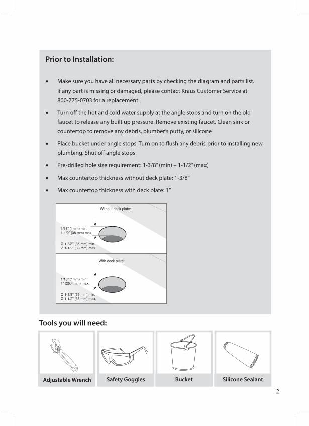
Prior to Installation:
• Make sure you have all necessary parts by checking the diagram and parts list.
If any part is missing or damaged, please contact Kraus Customer Service at
800-775-0703 for a replacement
• Turn off the hot and cold water supply at the angle stops and turn on the old
faucet to release any built up pressure. Remove existing faucet. Clean sink or
countertop to remove any debris, plumber’s putty, or silicone
• Place bucket under angle stops. Turn on to flush any debris prior to installing new
plumbing. Shut off angle stops
• Pre-drilled hole size requirement: 1-3/8” (min) – 1-1/2” (max)
• Max countertop thickness without deck plate: 1-3/8”
• Max countertop thickness with deck plate: 1”
Without deck plate:
With deck plate:
1/16” (1mm) min. 1-1/2” (38 mm) max.
Ø 1-3/8” (35 mm) min.Ø 1-1/2” (38 mm) max.
1/16” (1mm) min. 1” (25.4 mm) max.
Ø 1-3/8” (35 mm) min.Ø 1-1/2” (38 mm) max.
1
2
Designated Mark
Hot
Upward
Blac
k
Cold
1A 1B
2 3 4
5 67
GG
E E F
G
G
G
G
F
F
F
E
EH
E
EA
A
I
B
J
D
D
C D
G
Half Moon Locking NutsHalf Moon Locking Nuts
Rubber Caps
Tools you will need:
Adjustable Wrench Safety Goggles Bucket Silicone Sealant
6 5/8”
5 4/5”
3/8”(10mm)
7/8”
19.7º (22mm)
8 5/16”
1 1/4-18UNF-2A
(21mm)10 1/8”
(257mm)
1 3/8”(35mm)
3 3/4”
(168mm)
(147.3mm)
(96mm)
∅ 1 3/4”(∅ 45mm)
∅ 1 15/16”(∅ 50mm)
9/16”-18UNEF
27m
m ~
41.
3mm
1 1/
16”
~ 1
5/8”
∅ 1 15/16”(∅ 50mm)
12 7/16”(316mm)
1 5/8”(42.5 mm Max)
7A
8B8C
8D
8A
7A
8B8C
8D
8A
Adjustable wrench Phillips screwdriver
Tools You Will Need
Hex wrench Silicone Sealant
A
I
D
JF
B
G
C
H
E
3
A
C
B
D
J
EFG
H
I
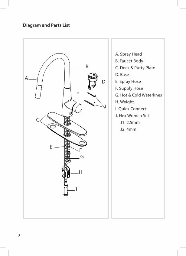
Diagram and Parts List
A. Spray Head
B. Faucet Body
C. Deck & Putty Plate
D. Base
E. Spray Hose
F. Supply Hose
G. Hot & Cold Waterlines
H. Weight
I. Quick Connect
J. Hex Wrench Set
J1. 2.5mm
J2. 4mm
4
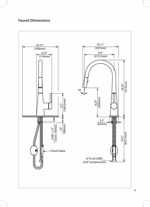
9/16-24 UNEF(3/8” Compression)
Check Value
0.06
”~1.
3”
(1m
m~3
0mm
)
1.6”
(4
0mm
)
2.5” (63mm)
10.11” (257mm)
8.4” (213.5mm)
10.15” (258mm)
4.33” (110mm)
8.25
” (2
09m
m)
6.7”
(1
69.5
mm
)
10º
24.5
” (6
22.7
mm
)16
.25”
(4
13m
m)
Faucet Dimensions
5
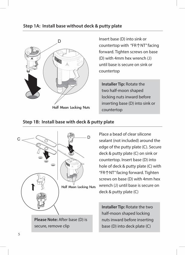
Step 1A: Install base without deck & putty plate
Insert base (D) into sink or countertop with “FR↑NT” facing forward. Tighten screws on base (D) with 4mm hex wrench (J) until base is secure on sink or countertop
Step 1B: Install base with deck & putty plate
Place a bead of clear silicone sealant (not included) around the edge of the putty plate (C). Secure deck & putty plate (C) on sink or countertop. Insert base (D) into hole of deck & putty plate (C) with “FR↑NT” facing forward. Tighten screws on base (D) with 4mm hex wrench (J) until base is secure on deck & putty plate (C)
Without deck plate:
With deck plate:
1/16” (1mm) min. 1-1/2” (38 mm) max.
Ø 1-3/8” (35 mm) min.Ø 1-1/2” (38 mm) max.
1/16” (1mm) min. 1” (25.4 mm) max.
Ø 1-3/8” (35 mm) min.Ø 1-1/2” (38 mm) max.
1
2
Designated Mark
Hot
Upward
Blac
k
Cold
1A 1B
2 3 4
5 67
GG
E E F
G
G
G
G
F
F
F
E
EH
E
EA
A
I
B
J
D
D
C D
G
Half Moon Locking NutsHalf Moon Locking Nuts
Rubber Caps
Installer Tip: Rotate the two half-moon shaped locking nuts inward before inserting base (D) into deck plate (C)
Installer Tip: Rotate the two half-moon shaped locking nuts inward before inserting base (D) into sink or countertop
Please Note: After base (D) is secure, remove clip
6
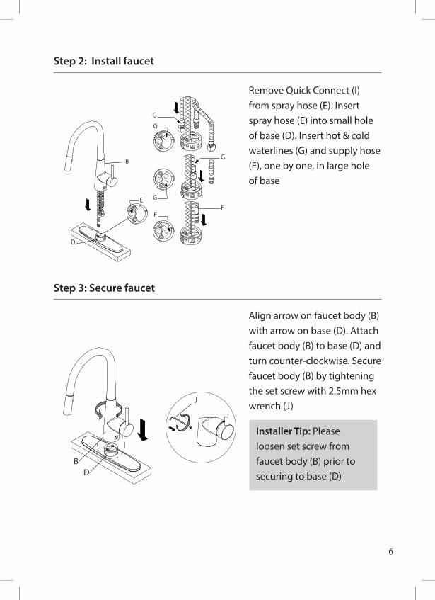
Step 2: Install faucet
Step 3: Secure faucet
Remove Quick Connect (I) from spray hose (E). Insert spray hose (E) into small hole of base (D). Insert hot & cold waterlines (G) and supply hose (F), one by one, in large hole of base
Align arrow on faucet body (B) with arrow on base (D). Attach faucet body (B) to base (D) and turn counter-clockwise. Secure faucet body (B) by tightening the set screw with 2.5mm hex wrench (J)
G
G
G
G
FF
B
D
E
F
F
E
I
I
I
J
BD
HotColdG
G
Designated Mark
HE
A
E
A
E
Rubber Cap
G
G
G
G
FF
B
D
E
F
F
E
I
I
I
J
BD
HotColdG
G
Designated Mark
HE
A
E
A
E
Rubber Cap
Installer Tip: Please loosen set screw from faucet body (B) prior to securing to base (D)
7
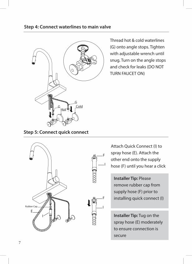
Step 4: Connect waterlines to main valve
Step 5: Connect quick connect
Thread hot & cold waterlines (G) onto angle stops. Tighten with adjustable wrench until snug. Turn on the angle stops and check for leaks (DO NOT TURN FAUCET ON)
Attach Quick Connect (I) to spray hose (E). Attach the other end onto the supply hose (F) until you hear a click
Installer Tip: Tug on the spray hose (E) moderately to ensure connection is secure
Installer Tip: Please remove rubber cap from supply hose (F) prior to installing quick connect (I)
G
G
G
G
FF
B
D
E
F
F
E
I
I
I
J
BD
HotColdG
G
Designated Mark
HE
A
E
A
E
Rubber Cap
G
G
G
G
FF
B
D
E
F
F
E
I
I
I
J
BD
HotColdG
G
Designated Mark
HE
A
E
A
E
Rubber Cap
G
G
G
G
FF
B
D
E
F
F
E
I
I
I
J
BD
HotColdG
G
Designated Mark
HE
A
E
A
E
Rubber Cap
8
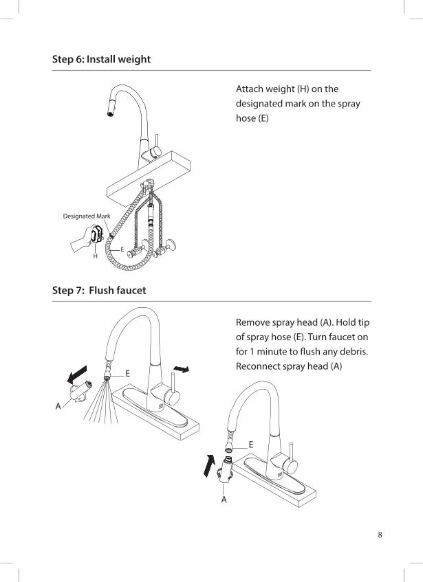
Step 6: Install weight
Step 7: Flush faucet
Attach weight (H) on the designated mark on the spray hose (E)
Remove spray head (A). Hold tip of spray hose (E). Turn faucet on for 1 minute to flush any debris. Reconnect spray head (A)
G
G
G
G
FF
B
D
E
F
F
E
I
I
I
J
BD
HotColdG
G
Designated Mark
HE
A
E
A
E
Rubber Cap
G
G
G
G
FF
B
D
E
F
F
E
I
I
I
J
BD
HotColdG
G
Designated Mark
HE
A
E
A
E
Rubber Cap
G
G
G
G
FF
B
D
E
F
F
E
I
I
I
J
BD
HotColdG
G
Designated Mark
HE
A
E
A
E
Rubber Cap
9
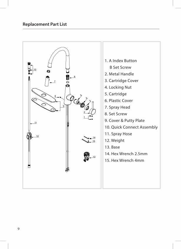
Replacement Part List
9
6
1
2
7
8
10
13
1415
5
34
12
11
1 Index Button A66D5582 Metal Handle A662358-50-T3 Trim Cap A1030624 Locking Nut A1040725 Ceramic Disc Cartridge A507348N6 Pattern Clip A0123577 Handle Spray w/Check Valve A528023N-548 Screw A0080039 Cover Plate & Putty Plate A66F48P-T10 Hose Adaptor Assembly A66G142N11 Spray Hose A514001WKP12 Weight A50407113 Hex Wrench(1*H2.5*53L) A03121714 Hex Wrench (H2.5 * 19 mm L * 53 mm L) A031011NI15 Shank Assembly A504027CP
1. A Index Button
B Set Screw
2. Metal Handle
3. Cartridge Cover
4. Locking Nut
5. Cartridge
6. Plastic Cover
7. Spray Head
8. Set Screw
9. Cover & Putty Plate
10. Quick Connect Assembly
11. Spray Hose
12. Weight
13. Base
14. Hex Wrench 2.5mm
15. Hex Wrench 4mm
10
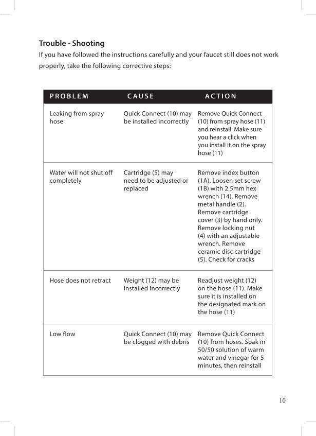
Trouble - Shooting If you have followed the instructions carefully and your faucet still does not work
properly, take the following corrective steps:
P R O B L E M C A U S E A C T I O N
Leaking from spray hose
Quick Connect (10) may be installed incorrectly
Remove Quick Connect (10) from spray hose (11) and reinstall. Make sure you hear a click when you install it on the spray hose (11)
Water will not shut off completely
Cartridge (5) may need to be adjusted or replaced
Remove index button (1A). Loosen set screw (1B) with 2.5mm hex wrench (14). Remove metal handle (2). Remove cartridge cover (3) by hand only. Remove locking nut (4) with an adjustable wrench. Remove ceramic disc cartridge (5). Check for cracks
Hose does not retract Weight (12) may be installed incorrectly
Readjust weight (12) on the hose (11). Make sure it is installed on the designated mark on the hose (11)
Low flow Quick Connect (10) may be clogged with debris
Remove Quick Connect (10) from hoses. Soak in 50/50 solution of warm water and vinegar for 5 minutes, then reinstall
11
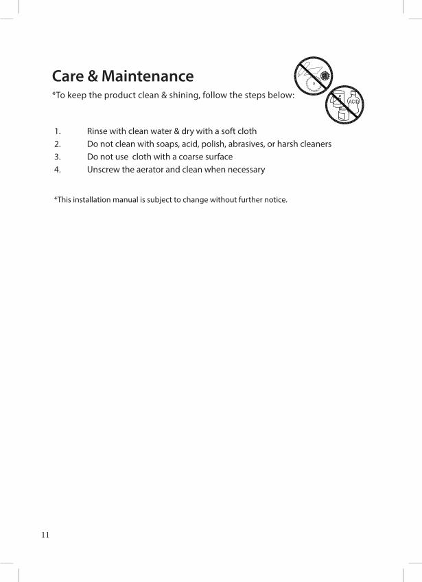
Care & Maintenance*To keep the product clean & shining, follow the steps below:
1. Rinse with clean water & dry with a soft cloth2. Do not clean with soaps, acid, polish, abrasives, or harsh cleaners3. Do not use cloth with a coarse surface4. Unscrew the aerator and clean when necessary
*This installation manual is subject to change without further notice.
1
10
279
10 3
1/32
”
Minimum distance 90mm
Less than 90mm
Cold Water
32 3
/32”
Ø35~Ø38
1
23
10
911
12 13
Hexagon Nut
HotWater
ColdWater
2 3
1
4576
8
45
67
8
Ø1 3/8”~Ø1 1/2”
815
1947 5/8”
Ø1 3/8~Ø1 1/2”
30˚
10 11
Close
Open LeftHot Water
Push
25˚ 90˚
12
13
87
Ø35~Ø38
Max
35
2178 17/32”
Max
1 3/
8”
9
11
1213
2345678
12
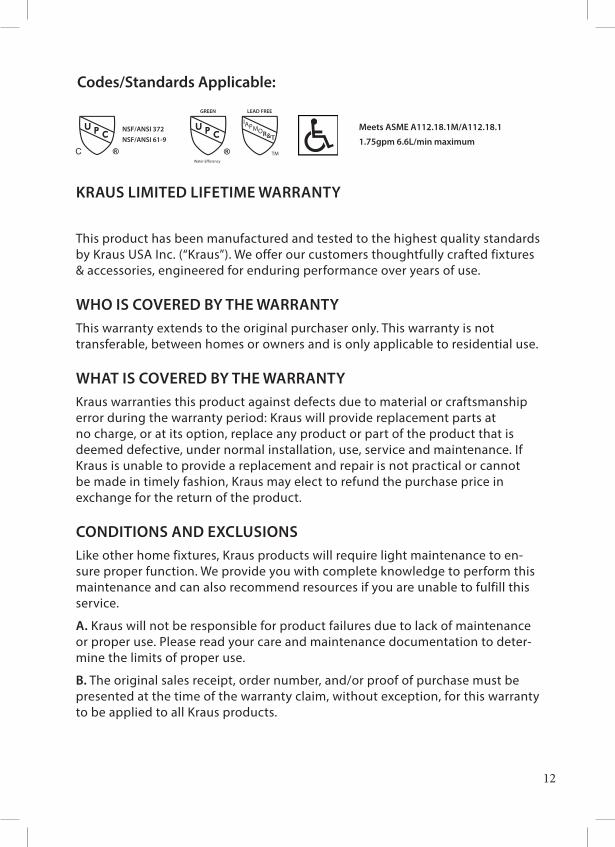
Codes/Standards Applicable:
Meets ASME A112.18.1M/A112.18.1
1.75gpm 6.6L/min maximum
GREEN
Water Efficiency
LEAD FREE
IAPMOR&T
TM
NSF/ANSI 61-9NSF/ANSI 372
KRAUS LIMITED LIFETIME WARRANTY
This product has been manufactured and tested to the highest quality standards by Kraus USA Inc. (“Kraus”). We offer our customers thoughtfully crafted fixtures & accessories, engineered for enduring performance over years of use.
WHO IS COVERED BY THE WARRANTYThis warranty extends to the original purchaser only. This warranty is not transferable, between homes or owners and is only applicable to residential use.
WHAT IS COVERED BY THE WARRANTY Kraus warranties this product against defects due to material or craftsmanship error during the warranty period: Kraus will provide replacement parts at no charge, or at its option, replace any product or part of the product that is deemed defective, under normal installation, use, service and maintenance. If Kraus is unable to provide a replacement and repair is not practical or cannot be made in timely fashion, Kraus may elect to refund the purchase price in exchange for the return of the product.
CONDITIONS AND EXCLUSIONSLike other home fixtures, Kraus products will require light maintenance to en-sure proper function. We provide you with complete knowledge to perform this maintenance and can also recommend resources if you are unable to fulfill this service.
A. Kraus will not be responsible for product failures due to lack of maintenance or proper use. Please read your care and maintenance documentation to deter-mine the limits of proper use.
B. The original sales receipt, order number, and/or proof of purchase must be presented at the time of the warranty claim, without exception, for this warranty to be applied to all Kraus products.
13
C. Kraus recommends installing all Kraus products with a licensed, professional plumber. Kraus will not be held responsible for any damage or product failure due to improper installation, misuse, or failure to use a licensed professional. Please read your care and maintenance documentation to determine the limits of proper use.
D. Commercial use will automatically void this warranty.
E. This warranty is not applicable to Kraus products purchased from an unau-thorized seller. For a complete list of authorized sellers please visit http://www.kraususa.com/where-to-buy.html
NON-APPLICABILITY OF THIS WARRANTYBy the purchase and use of our products, you agree that Kraus is not liable for incidental, consequential or special damages associated with the return, replacement, installation or use of your product. This includes freight costs, cartridge replacement, labor, travel time, lost profit, home damages and other contingent liabilities and costs (including, without limitation, costs associated with experts, investigations, analyses, attorneys and other professionals and services). The Kraus warranty is a comprehensive and explicit limit of liability, and all items outside of it are not addressable by or the responsibility of Kraus. Certain states have variances regarding implied warranties and in those situations we remain fully compliant.
KRAUS USA Inc. makes no implication that products comply with any or all local building or plumbing codes. It is the consumer’s responsibility to determine local code compliance. This warranty extends to the original purchaser and first consumer.
14
If you are a homeowner please contact a Kraus Customer Service Representative at:
Kraus USA, Inc. 12 Harbor Park DrivePort Washington, NY 11050Toll-free [email protected]
If you are a plumbing contractor or trade professional please contact a Kraus Pro Representative at:
Kraus USA, Inc. 12 Harbor Park DrivePort Washington, NY [email protected]
If you are an Authorized Partner please contact a Partner Support Representative at:
Kraus USA, Inc. 12 Harbor Park DrivePort Washington, NY [email protected]
In requesting warranty service, please be ready to provide:
1. Proof of purchase. 2. A description of the problem.
HELP LINEOur customer service hours are Monday – Friday, 9am – 8pm EST.Be sure to visit our website at www.kraususa.com

www.kraususa.com