Embed Size (px)
Citation preview
HEADQUARTERS FM 3-22.68DEPARTMENT OF THE ARMY
CREW-SERVED MACHINE GUNS,5.56-mm AND 7.62-mm
M249, 5.56-MM MACHINE GUN
M60, 7.62-MM MACHINE GUN
M240B, 7.62-MM MACHINE GUN
JANUARY 2003
DISTRIBUTION RESTRICTION: Approved for public release; distribution is unlimited.
*FM 3-22.68
i
FIELD MANUAL HEADQUARTERSNo. 3-22.68 DEPARTMENT OF THE ARMY
Washington, DC, 31 January 2003
CREW-SERVED MACHINE GUNS,5.56-mm AND 7.62-mm
CONTENTSPage
PREFACE......................................................................................................................... vi
CHAPTER 1. M249 MACHINE GUNSection I. Description and Components................................................................ 1-1
1-1. Description................................................................................ 1-11-2. Components .............................................................................. 1-31-3. Ammunition.............................................................................. 1-51-4. Blank Firing Attachment .......................................................... 1-8
Section II. Maintenance.......................................................................................... 1-91-5. Clearing Procedures.................................................................. 1-91-6. General Disassembly .............................................................. 1-111-7. Inspection................................................................................ 1-161-8. Cleaning, Lubrication, and Preventive Maintenance.............. 1-181-9. General Assembly................................................................... 1-211-10. Function Check....................................................................... 1-241-11. Maintenance Procedures......................................................... 1-251-12. Maintenance During Nuclear, Biological, Chemical
Conditions............................................................................... 1-25Section III. Operation and Function ...................................................................... 1-25
1-13. Operation ................................................................................ 1-251-14. Loading................................................................................... 1-261-15. Unloading ............................................................................... 1-271-16. Cycle of Functioning .............................................................. 1-271-17. Sights ...................................................................................... 1-291-18. M122 Tripod........................................................................... 1-311-19. Dismounting from the M122 Tripod ...................................... 1-331-20. Bipod Operations.................................................................... 1-331-21. Vehicular Mount..................................................................... 1-341-22. Tripod Positioning .................................................................. 1-34
DISTRIBUTION RESTRICTION: Approved for public release; distribution isunlimited.
*This publication supersedes FM 23-67, 29 February 1984 and FM 23-14,26 January 1994.

FM 3-22.68
Page
ii
Section IV. Performance Problems and Destruction ............................................. 1-341-23. Malfunctions........................................................................... 1-341-24. Stoppages................................................................................ 1-351-25. Immediate Action ................................................................... 1-371-26. Remedial Action ..................................................................... 1-381-27. Destruction Procedures........................................................... 1-38
CHAPTER 2. M60 MACHINE GUNSection I. Description and Components................................................................ 2-1
2-1. Description................................................................................ 2-12-2. Components .............................................................................. 2-32-3. Ammunition.............................................................................. 2-62-4. Blank Firing Attachments, M13 and M13A............................. 2-7
Section II. Maintenance.......................................................................................... 2-92-5. Clearing Procedures.................................................................. 2-92-6. General Disassembly .............................................................. 2-102-7. Inspection................................................................................ 2-162-8. Cleaning, Lubrication, and Preventive Maintenance.............. 2-172-9. General Assembly................................................................... 2-192-10. Function Check....................................................................... 2-212-11. Maintenance Procedures......................................................... 2-222-12. Maintenance During Nuclear, Biological, Chemical
Conditions............................................................................... 2-22Section III. Operation and Function .......................................................... 2-22
2-13. Operation ................................................................................ 2-222-14. Loading................................................................................... 2-222-15. Unloading…. .......................................................................... 2-232-16. Cycle of Functioning .............................................................. 2-232-17. Sights ...................................................................................... 2-252-18. M122 Tripod........................................................................... 2-262-19. Bipod Operations.................................................................... 2-282-20. Vehicular Mount..................................................................... 2-292-21. Tripod Position ....................................................................... 2-30
Section IV. Performance Problems and Destruction ............................................. 2-302-22. Malfunctions........................................................................... 2-302-23. Stoppages................................................................................ 2-312-24. Immediate Action ................................................................... 2-322-25. Remedial Action ..................................................................... 2-332-26. Destruction Procedures........................................................... 2-34
CHAPTER 3. M240B MACHINE GUNSection I. Description and Components................................................................ 3-1
3-1. Description................................................................................ 3-13-2. Components .............................................................................. 3-33-3. Ammunition.............................................................................. 3-53-4. Ammunition Adapter................................................................ 3-6
FM 3-22.68
Page
iii
3-5. Blank Firing Attachment .......................................................... 3-7Section II. Maintenance.......................................................................................... 3-9
3-6. Clearing Procedures.................................................................. 3-93-7. General Disassembly .............................................................. 3-113-8. Inspection................................................................................ 3-183-9. Cleaning, Lubrication, and Preventive Maintenance.............. 3-203-10. General Assembly................................................................... 3-243-11. Function Check....................................................................... 3-273-12. Maintenance Procedures......................................................... 3-273-13. Maintenance During Nuclear, Biological, Chemical
Conditions............................................................................... 3-27Section III. Operation and Function ...................................................................... 3-27
3-14. Operation ................................................................................ 3-283-15. Loading................................................................................... 3-283-16. Unloading ............................................................................... 3-283-17. Cycle of Functioning ............................................................. 3-293-18. Sights ...................................................................................... 3-303-19. M122A1 Tripod...................................................................... 3-333-20. Bipod Operations.................................................................... 3-353-21. Tripod Operations................................................................... 3-36
Section IV. Performance Problems and Destruction ............................................. 3-363-22. Malfunctions........................................................................... 3-363-23. Stoppages................................................................................ 3-373-24. Immediate Action ................................................................... 3-403-25. Remedial Action ..................................................................... 3-403-26. Stuck Barrel ............................................................................ 3-413-27. Destruction Procedures........................................................... 3-41
CHAPTER 4. MACHINE GUN MARKSMANSHIP TRAININGSection I. Introduction........................................................................................... 4-1
4-1. Objectives ................................................................................. 4-14-2. Training Phases......................................................................... 4-14-3. Training Strategy ...................................................................... 4-24-4. Training for Combat Conditions .............................................. 4-4
Section II. Preliminary Gunnery............................................................................. 4-44-5. Marksmanship Fundamentals ................................................... 4-44-6. Firing Positions......................................................................... 4-54-7. Night Fire.................................................................................. 4-94-8. Nuclear, Biological, Chemical Fire ........................................ 4-104-9. Engagement of Moving Targets ............................................. 4-114-10. Traverse and Search................................................................ 4-134-11. Direct Lay............................................................................... 4-144-12. Application of Fire.................................................................. 4-144-13. Fire Adjustment ...................................................................... 4-144-14. Effects of Wind....................................................................... 4-154-15. Fire Commands....................................................................... 4-17
FM 3-22.68
Page
iv
4-16. Dry-Fire Exercise ................................................................... 4-174-17. Multipurpose Machine Gun Range Layout ............................ 4-204-18. Basic Machine Gun Target ..................................................... 4-214-19. Target Analysis....................................................................... 4-24
Section III. Crew Drill ........................................................................................... 4-244-20. Preparation.............................................................................. 4-244-21. Crew Equipment ..................................................................... 4-254-22. Formation (Bipod or Tripod Mounted) .................................. 4-254-23. Cross-Training Procedures ..................................................... 4-26
4-24. Inspection for Bipod Fire........................................................ 4-264-25. Placement into Action (Bipod) ............................................... 4-284-26 Procedures for Changing the Barrel (Bipod).......................... 4-294-27. Removal from Action (Bipod)................................................ 4-304-28. Inspection for Tripod Fire....................................................... 4-304-29. Placement into Action (Tripod).............................................. 4-30
4-30. Procedures for Changing the Barrel (Tripod)......................... 4-324-31. Removal from Action (Tripod)............................................... 4-324-32. Prone Position......................................................................... 4-33
Section IV. Basic Gunnery for the M249, M60, and M240B Machine Guns ....... 4-344-33. Zero......................................................................................... 4-344-34. Field Zero ............................................................................... 4-354-35. 10-Meter Firing....................................................................... 4-354-36. 10-Meter Conduct of Fire ....................................................... 4-364-37. 10-Meter Firing, Qualification ............................................... 4-444-38. Transition Fire ........................................................................ 4-444-39. Transition Conduct of Fire, Bipod.......................................... 4-454-40. Transition Fire, Limited Visibility.......................................... 4-494-41. AN/PVS-4 Zero ...................................................................... 4-504-42. Qualification Standards .......................................................... 4-51
CHAPTER 5. COMBAT TECHNIQUES OF FIRESection I. Characteristics of Fire........................................................................... 5-1
5-1. Trajectory.................................................................................. 5-15-2. Maximum Ordinate .................................................................. 5-15-3. Cone of Fire .............................................................................. 5-15-4. Beaten Zone.............................................................................. 5-25-5. Danger Space............................................................................ 5-2
Section II. Classes of Fire....................................................................................... 5-25-6. Respect to the Ground .............................................................. 5-25-7. Respect to the Target ................................................................ 5-35-8. Respect to the Machine Gun..................................................... 5-4
Section III. Application of Fire................................................................................ 5-55-9. Types of Targets ....................................................................... 5-55-10. Distribution, Concentration, and Rate of Fire .......................... 5-65-11. Target Engagement................................................................... 5-75-12. Target Engagement during Limited Visibility........................ 5-12
FM 3-22.68
Page
v
5-13. Overhead Fire ......................................................................... 5-125-14. Defilade Positions................................................................... 5-14
Section IV. Predetermined Fires ............................................................................ 5-165-15. Terminology ........................................................................... 5-165-16. Range Card ............................................................................. 5-17
Section V. Fire Control......................................................................................... 5-235-17. Methods of Fire Control ......................................................... 5-235-18. Fire Commands....................................................................... 5-24
Section VI. Range Determination .......................................................................... 5-305-19. Range Estimation.................................................................... 5-305-20. Lateral Distance Measurement ............................................... 5-33
Section VII. Advanced Gunnery ............................................................................. 5-345-21. Objectives ............................................................................... 5-345-22. Organization ........................................................................... 5-345-23. Ammunition............................................................................ 5-345-24. Firing Sequence ...................................................................... 5-345-25. Alternate Firing Positions....................................................... 5-355-26. Movement, Speed, and Alignment ......................................... 5-385-27. Reloading................................................................................ 5-38
CHAPTER 6. TRAIN-THE-TRAINER PROGRAM6-1. Mission-Essential Task List...................................................... 6-16-2. Trainer Assessment................................................................... 6-16-3. Assistant Trainers and Cadre Coaches ..................................... 6-26-4. Program Phases......................................................................... 6-36-5. Training Tasks .......................................................................... 6-36-6. Trainer Certification Program ................................................ 6-11
APPENDIX A. UNIT TRAINING PROGRAM ......................................................... A-1APPENDIX B. PROFICIENCY (PERFORMANCE) EXAMINATION....................B-1APPENDIX C. AERIAL DEFENSE............................................................................C-1APPENDIX D. RANGE SAFETY.............................................................................. D-1APPENDIX E. EMPLOYMENT.................................................................................E-1APPENDIX F. TRAINING AIDS AND DEVICES....................................................F-1APPENDIX G. ADVANCED OPTICS AND LASERS............................................. G-1APPENDIX H. 10-METER BORE LIGHT/25-METER TARGET OFFSETS.......... H-1GLOSSARY........................................................................................................Glossary-1REFERENCES............................................................................................... References-1INDEX...................................................................................................................... Index-1
FM 3-22.68
vi
PREFACEThis manual provides technical information, training techniques, and guidance on the
crew-served machine guns, 5.56-mm and 7.62-mm (M249/M60/M240B). The purpose ofthis manual is, to provide a one-source document for all three weapons. This prohibitshaving several sources to rely on. Unit leaders, trainers, and the designated gunners willfind this information invaluable in their efforts to successfully integrate these automaticweapons into their combat operations.
Trainers must ensure that safety procedures are observed at all times. Leaders,trainers, and soldiers must remember that safety is everyone’s responsibility. All trainingshould be conducted as though the weapon is fully loaded. At no time while using thismanual does speed or accuracy override the safety procedures.
Unless this publication states otherwise, masculine nouns and pronouns do not referexclusively to men.
The proponent of this publication is the United States Army Infantry School. Sendcomments and recommendations on DA Form 2028 directly to Commandant, U.S. ArmyInfantry School, ATTN: ATSH-IN-S3, Fort Benning, GA 31905-5596, or send email [email protected].
FM 3-22.68
1-1
CHAPTER 1M249 MACHINE GUN
The 5.56-mm M249 machine gun supports the soldier in both theoffense and defense. The M249 provides a medium volume of close andcontinuous fire the soldier needs to accomplish the mission. With it, unitscan engage the enemy along with the capability of individual weaponswith controlled and accurate fire. The medium-range, close defensive, andfinal protective fires delivered by the M249 MG form an integral part of aunit’s defensive fires. Although the M249 MG is described here as amachine gun, it also plays the role of the automatic rifleman. This FM orchapter supersedes FM 23-14, which describes the M249 MG in theautomatic rifle role. This chapter also describes the weapon and the typesof ammunition in detail and provides a table of general data.
Section I. DESCRIPTION AND COMPONENTSThis section describes the M249 machine gun and its components and purposes. It alsodiscusses the different types of ammunition that is fired from the M249 machine gun.This section describes how to install the blank firing adapter for the M249 machine gunand how to take care of the machine gun while using the blank firing adapter.
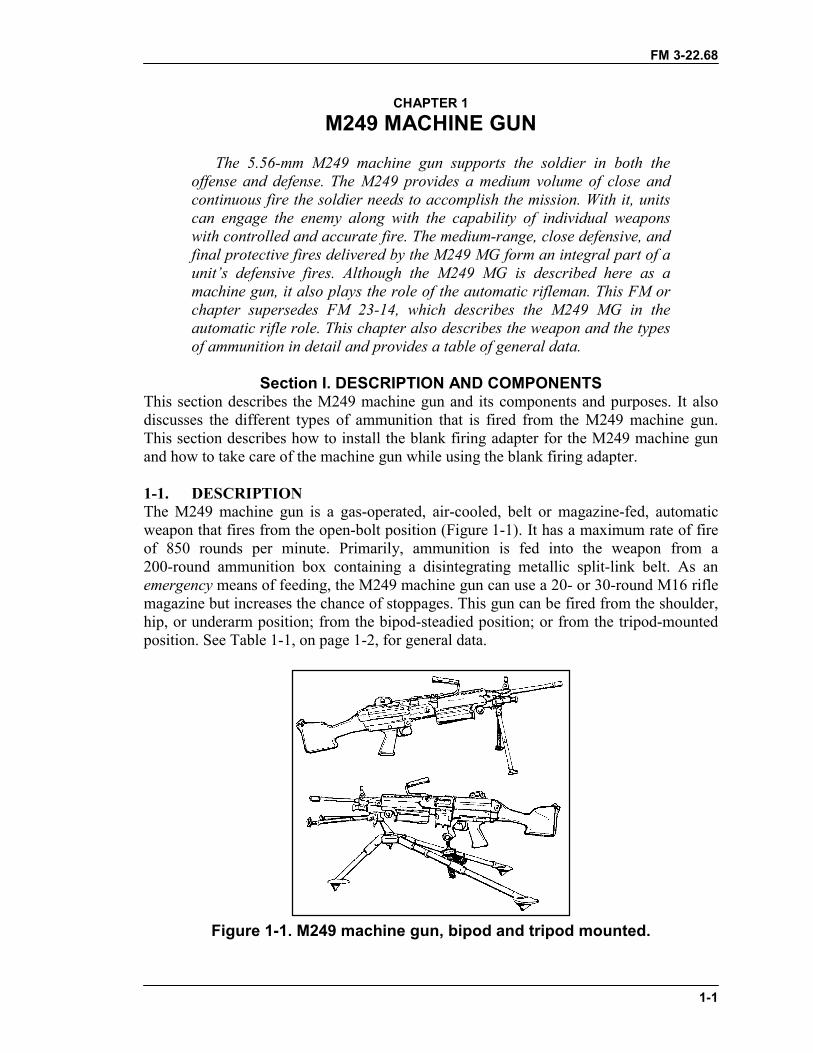
1-1. DESCRIPTIONThe M249 machine gun is a gas-operated, air-cooled, belt or magazine-fed, automaticweapon that fires from the open-bolt position (Figure 1-1). It has a maximum rate of fireof 850 rounds per minute. Primarily, ammunition is fed into the weapon from a200-round ammunition box containing a disintegrating metallic split-link belt. As anemergency means of feeding, the M249 machine gun can use a 20- or 30-round M16 riflemagazine but increases the chance of stoppages. This gun can be fired from the shoulder,hip, or underarm position; from the bipod-steadied position; or from the tripod-mountedposition. See Table 1-1, on page 1-2, for general data.
Figure 1-1. M249 machine gun, bipod and tripod mounted.

FM 3-22.68
1-2
Ammunition ..................................5.56-mm ball and tracer (4:1 mix) ammunition ispackaged in 200-round drums, each weighing6.92 pounds; other types of ammunition available areball, tracer, blank, and dummy.
Tracer burnout...............................900 meters (+)Length of M249 ............................40.87 inchesWeight of M249............................16.41 poundsWeight of tripod mount M122
with traversing and elevatingmechanism and pintle...............16 pounds
Maximum range ............................3,600 metersMaximum effective range .............1,000 meters with the tripod and T&EArea:
Tripod.......................................1,000 metersBipod........................................800 meters
Point:Tripod.......................................800 metersBipod........................................600 meters
Suppression ...................................1,000 metersMaximum extent of grazing
fire obtainable over uniformlysloping terrain...........................600 meters
Height of M249 on tripodmount M122A1...................…… 16 inches
Rates of Fire:Sustained ..................................100 rounds per minute
Fired in 6- to 9-round bursts with 4 to 5 secondsbetween bursts (change barrel every 10 minutes)
Rapid ........................................200 rounds per minuteFired in 6- to 9-round bursts2 to 3 seconds between bursts (change barrel every2 minutes)
Cyclic .......................................650 to 850 rounds per minuteContinuous burst (change barrel every minute)
Basic load, ammunition ................1,000 rounds (in 200-round drums)Elevation, tripod controlled ..........+200 milsElevation, tripod free ....................+445 milsDepression, tripod controlled........-200 milsDepression, tripod free..................-445 milsTraverse, controlled by traversing
and elevating mechanism .........100 milsNormal sector of fire (with
tripod)..........…………….........875 mils
Table 1-1. General data.

FM 3-22.68
1-3
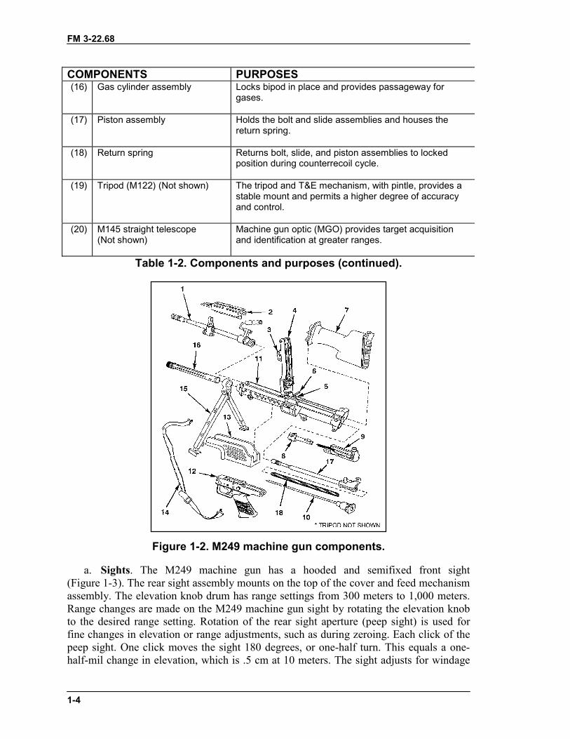
1-2. COMPONENTSThe components of the M249 machine gun and their purposes are described in Table 1-2and shown Figure 1-2. The item numbers in Table 1-2 correspond to the callout numbersin Figure 1-2. The sights and safety button are shown in Figures 1-3 and 1-4. (SeeTable 1-1 for general data.)
COMPONENTS PURPOSES(1) Barrel assembly Houses cartridges for firing, directs projectile, and
supports the gas regulator.
(2) Heat shield assembly Provides protection for the gunner’s hand from a hotbarrel.
(3) Rear sight assembly Adjusts for both windage and elevation.
(4) Cover and feed mechanismassembly
Feeds linked belt ammunition, and positions and holdscartridges in position for stripping, feeding, andchambering.
(5) Feed tray assembly Positions belted ammunition for firing.
(6) Cocking handle assembly Pulls the moving parts rearward. Moves in a guide railfixed to the right side of the receiver.
(7) Buttstock and buffer assembly Contains a folding buttplate. Serves as a shouldersupport for aiming and firing M249. Contains a foldingshoulder rest and a hydraulic buffer to absorb the recoil.
(8) Bolt assembly Provides feeding, stripping, chambering, firing, andextraction, using the projectile gases for power.
(9) Slide assembly Houses firing pin and roller assembly.
(10) Return rod and transfermechanism assembly
Absorbs recoil for bolt and operating rod assembly at theend of recoil movement.
(11) Receiver assembly Serves as a support for all major components andhouses action of weapon. Through a series of camways, controls functioning of weapon.
(12) Trigger mechanism Controls the firing of the weapon. Provides storage areafor lubricant in grip portion.
(13) Handguard assembly Provides thermal insulation to protect the gunner’s handfrom heat or extreme cold and houses the cleaningequipment.
(14) Sling and snap hook assembly Provides a means of carrying the weapon.
(15) Bipod Supports the M249 machine gun in the prone position.The telescopic legs can be individually adjusted to threedifferent lengths.
Table 1-2. Components and purposes.
FM 3-22.68
1-4
COMPONENTS PURPOSES(16) Gas cylinder assembly Locks bipod in place and provides passageway for
gases.
(17) Piston assembly Holds the bolt and slide assemblies and houses thereturn spring.
(18) Return spring Returns bolt, slide, and piston assemblies to lockedposition during counterrecoil cycle.
(19) Tripod (M122) (Not shown) The tripod and T&E mechanism, with pintle, provides astable mount and permits a higher degree of accuracyand control.
(20) M145 straight telescope(Not shown)
Machine gun optic (MGO) provides target acquisitionand identification at greater ranges.
Table 1-2. Components and purposes (continued).
Figure 1-2. M249 machine gun components.
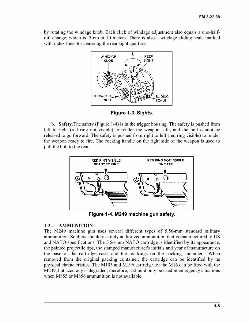
a. Sights. The M249 machine gun has a hooded and semifixed front sight(Figure 1-3). The rear sight assembly mounts on the top of the cover and feed mechanismassembly. The elevation knob drum has range settings from 300 meters to 1,000 meters.Range changes are made on the M249 machine gun sight by rotating the elevation knobto the desired range setting. Rotation of the rear sight aperture (peep sight) is used forfine changes in elevation or range adjustments, such as during zeroing. Each click of thepeep sight. One click moves the sight 180 degrees, or one-half turn. This equals a one-half-mil change in elevation, which is .5 cm at 10 meters. The sight adjusts for windage
FM 3-22.68
1-5
by rotating the windage knob. Each click of windage adjustment also equals a one-half-mil change, which is .5 cm at 10 meters. There is also a windage sliding scale markedwith index lines for centering the rear sight aperture.
Figure 1-3. Sights.
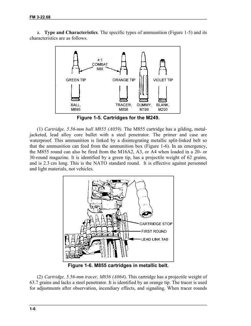
b. Safety.The safety (Figure 1-4) is in the trigger housing. The safety is pushed fromleft to right (red ring not visible) to render the weapon safe, and the bolt cannot bereleased to go forward. The safety is pushed from right to left (red ring visible) to renderthe weapon ready to fire. The cocking handle on the right side of the weapon is used topull the bolt to the rear.
Figure 1-4. M249 machine gun safety.
1-3. AMMUNITIONThe M249 machine gun uses several different types of 5.56-mm standard militaryammunition. Soldiers should use only authorized ammunition that is manufactured to USand NATO specifications. The 5.56-mm NATO cartridge is identified by its appearance,the painted projectile tips, the stamped manufacturer's initials and year of manufacture onthe base of the cartridge case, and the markings on the packing containers. Whenremoved from the original packing container, the cartridge can be identified by itsphysical characteristics. The M193 and M196 cartridge for the M16 can be fired with theM249, but accuracy is degraded; therefore, it should only be used in emergency situationswhen M855 or M856 ammunition is not available.
FM 3-22.68
1-6
a. Type and Characteristics. The specific types of ammunition (Figure 1-5) and itscharacteristics are as follows.
Figure 1-5. Cartridges for the M249.
(1) Cartridge, 5.56-mm ball M855 (A059). The M855 cartridge has a gilding, metal-jacketed, lead alloy core bullet with a steel penetrator. The primer and case arewaterproof. This ammunition is linked by a disintegrating metallic split-linked belt sothat the ammunition can feed from the ammunition box (Figure 1-6). In an emergency,the M855 round can also be fired from the M16A2, A3, or A4 when loaded in a 20- or30-round magazine. It is identified by a green tip, has a projectile weight of 62 grains,and is 2.3 cm long. This is the NATO standard round. It is effective against personneland light materials, not vehicles.
Figure 1-6. M855 cartridges in metallic belt.
(2) Cartridge, 5.56-mm tracer, M856 (A064). This cartridge has a projectile weight of63.7 grains and lacks a steel penetrator. It is identified by an orange tip. The tracer is usedfor adjustments after observation, incendiary effects, and signaling. When tracer rounds
FM 3-22.68
1-7
are fired, they are mixed with ball ammunition in a ratio of four ball rounds to one tracerround. The DODAC for ball and tracer mix is A064.
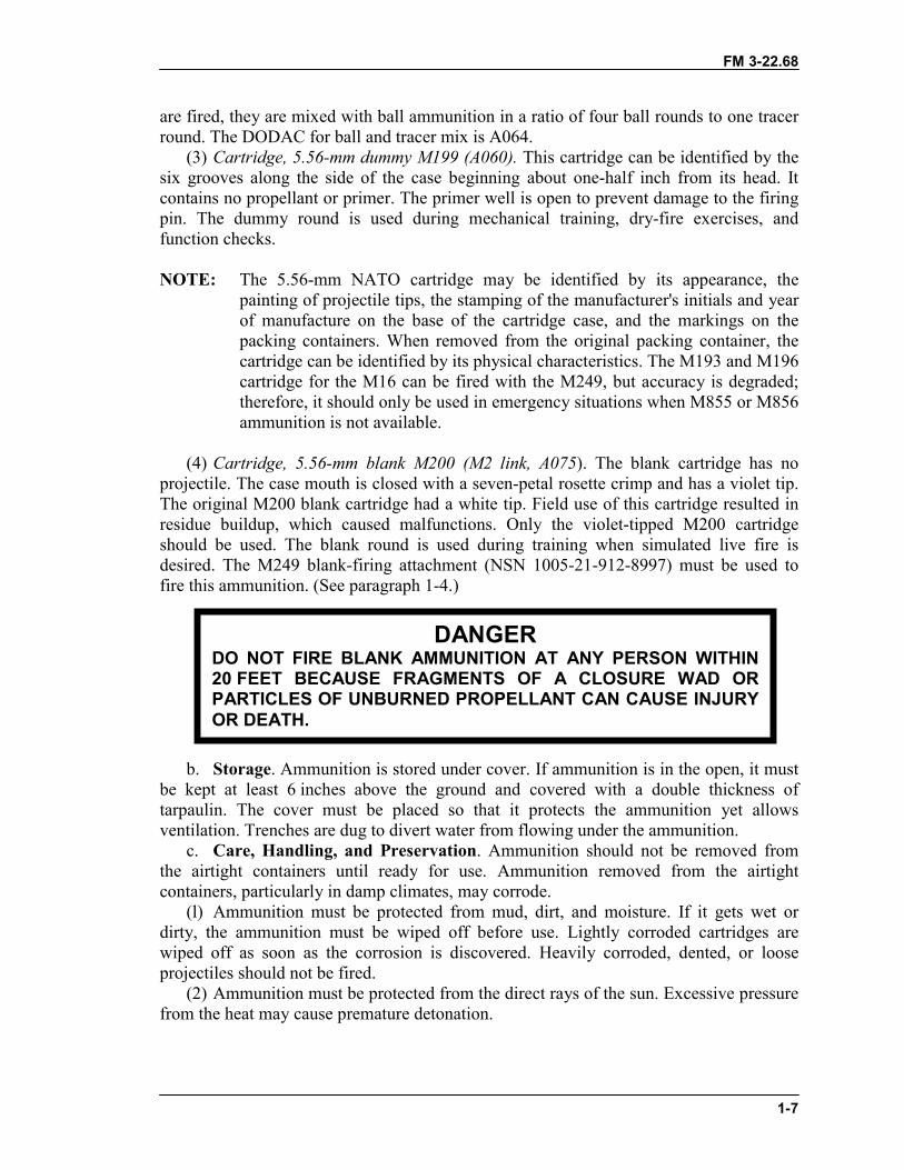
(3) Cartridge, 5.56-mm dummy M199 (A060). This cartridge can be identified by thesix grooves along the side of the case beginning about one-half inch from its head. Itcontains no propellant or primer. The primer well is open to prevent damage to the firingpin. The dummy round is used during mechanical training, dry-fire exercises, andfunction checks.
NOTE: The 5.56-mm NATO cartridge may be identified by its appearance, thepainting of projectile tips, the stamping of the manufacturer's initials and yearof manufacture on the base of the cartridge case, and the markings on thepacking containers. When removed from the original packing container, thecartridge can be identified by its physical characteristics. The M193 and M196cartridge for the M16 can be fired with the M249, but accuracy is degraded;therefore, it should only be used in emergency situations when M855 or M856ammunition is not available.
(4) Cartridge, 5.56-mm blank M200 (M2 link, A075). The blank cartridge has noprojectile. The case mouth is closed with a seven-petal rosette crimp and has a violet tip.The original M200 blank cartridge had a white tip. Field use of this cartridge resulted inresidue buildup, which caused malfunctions. Only the violet-tipped M200 cartridgeshould be used. The blank round is used during training when simulated live fire isdesired. The M249 blank-firing attachment (NSN 1005-21-912-8997) must be used tofire this ammunition. (See paragraph 1-4.)
b. Storage. Ammunition is stored under cover. If ammunition is in the open, it mustbe kept at least 6 inches above the ground and covered with a double thickness oftarpaulin. The cover must be placed so that it protects the ammunition yet allowsventilation. Trenches are dug to divert water from flowing under the ammunition.
c. Care, Handling, and Preservation. Ammunition should not be removed fromthe airtight containers until ready for use. Ammunition removed from the airtightcontainers, particularly in damp climates, may corrode.
(l) Ammunition must be protected from mud, dirt, and moisture. If it gets wet ordirty, the ammunition must be wiped off before use. Lightly corroded cartridges arewiped off as soon as the corrosion is discovered. Heavily corroded, dented, or looseprojectiles should not be fired.
(2) Ammunition must be protected from the direct rays of the sun. Excessive pressurefrom the heat may cause premature detonation.
DANGERDO NOT FIRE BLANK AMMUNITION AT ANY PERSON WITHIN20 FEET BECAUSE FRAGMENTS OF A CLOSURE WAD ORPARTICLES OF UNBURNED PROPELLANT CAN CAUSE INJURYOR DEATH.
FM 3-22.68
1-8
(3) Oil should never be used on ammunition. Oil collects dust and other abrasivesthat may possibly damage the operating parts of the weapon.
d. Packaging. The ammunition can contains two plastic ammunition drums. Eachdrum contains 200 rounds and weighs 6.92 pounds. Dummy ammunition (M199) ispacked in boxes of 20 rounds each.
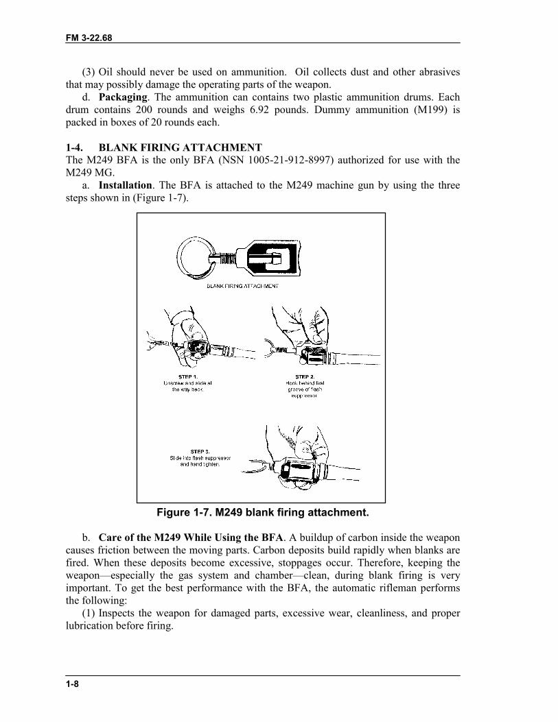
1-4. BLANK FIRING ATTACHMENTThe M249 BFA is the only BFA (NSN 1005-21-912-8997) authorized for use with theM249 MG.
a. Installation. The BFA is attached to the M249 machine gun by using the threesteps shown in (Figure 1-7).
Figure 1-7. M249 blank firing attachment.
b. Care of the M249 While Using the BFA. A buildup of carbon inside the weaponcauses friction between the moving parts. Carbon deposits build rapidly when blanks arefired. When these deposits become excessive, stoppages occur. Therefore, keeping theweapon—especially the gas system and chamber—clean, during blank firing is veryimportant. To get the best performance with the BFA, the automatic rifleman performsthe following:
(1) Inspects the weapon for damaged parts, excessive wear, cleanliness, and properlubrication before firing.
FM 3-22.68
1-9
(2) When feasible, test fires the weapon using ball ammunition before attachingthe BFA.
(3) Adjusts the BFA to fit the weapon.(4) Applies immediate action when stoppages occur.(5) Cleans the gas system after firing 500 rounds.(6) Cleans and lubricates the entire weapon after firing 1,000 rounds.
Section II. MAINTENANCEProper maintenance contributes to weapon effectiveness as well as to unit readiness. Thissection discusses the maintenance aspects of the M249 machine gun to includeinspection; cleaning and lubrication; maintenance before, during, and after firing, andduring NBC conditions. Associated tasks essential to maintenance (clearing, generalassembly and disassembly, and function checks) are provided in detail.
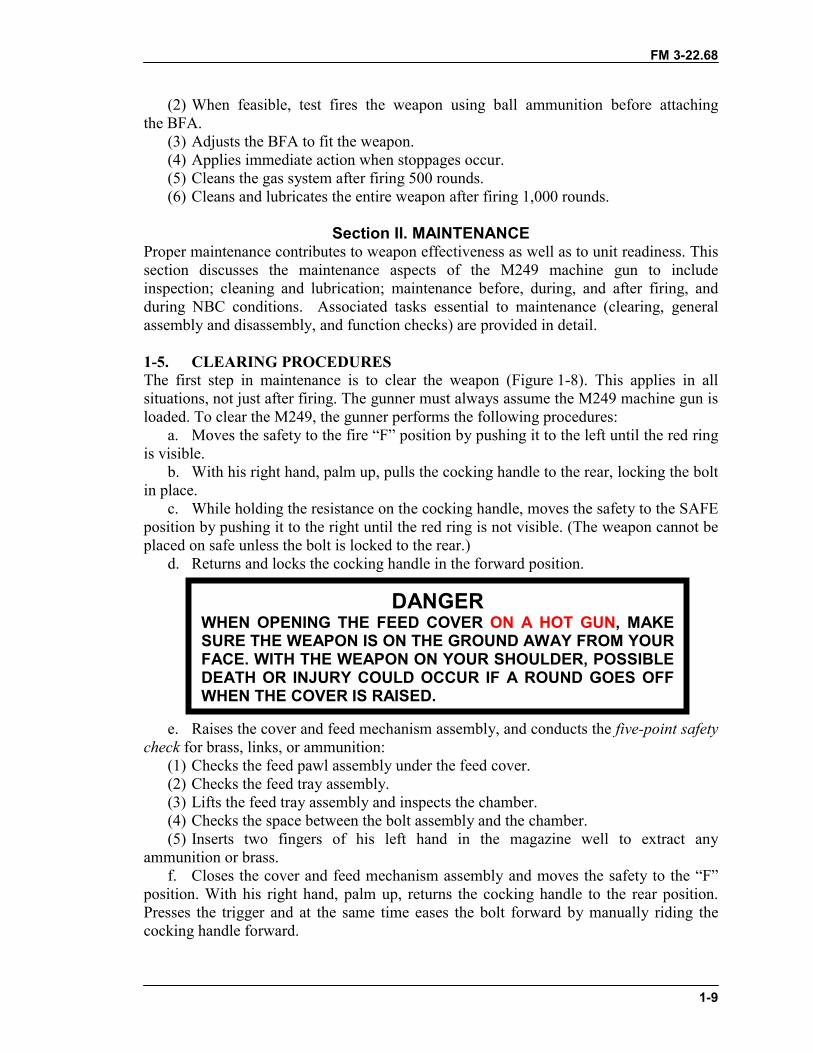
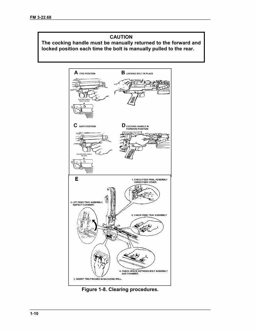
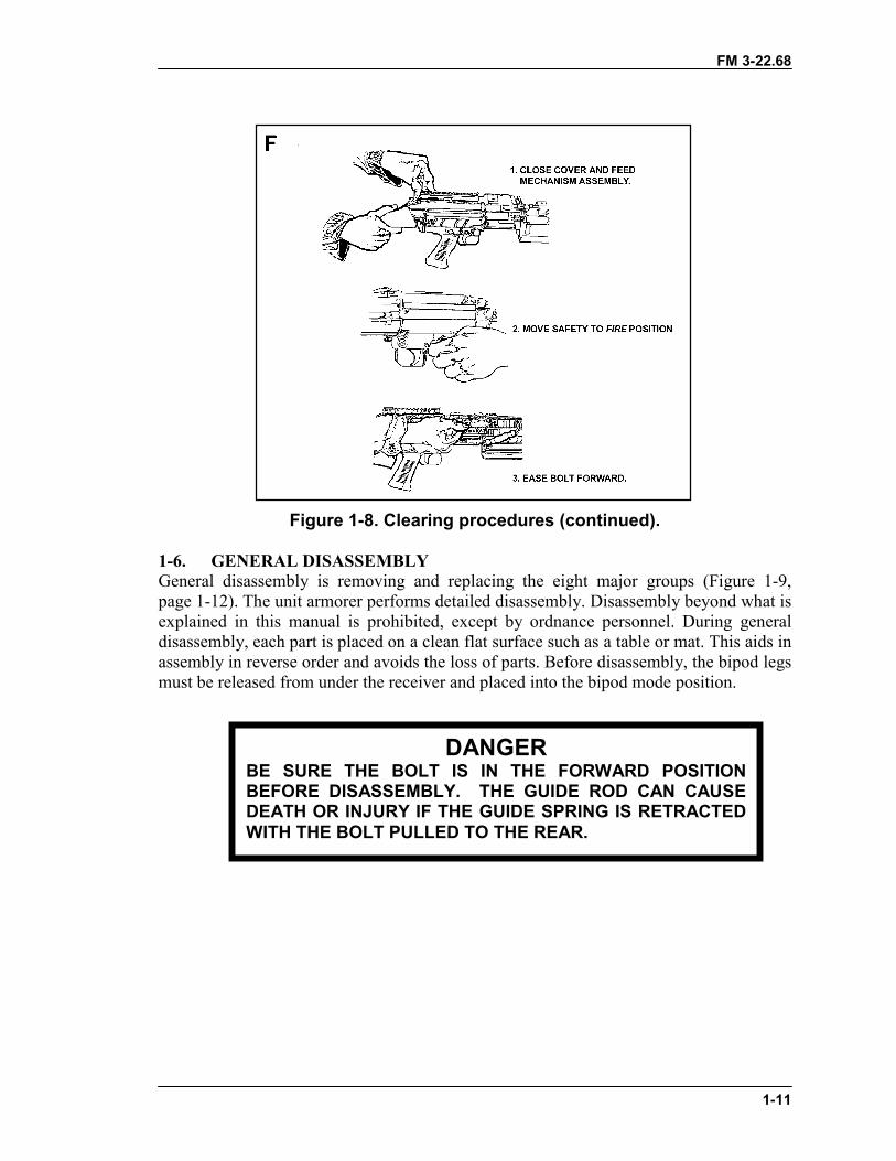
1-5. CLEARING PROCEDURESThe first step in maintenance is to clear the weapon (Figure 1-8). This applies in allsituations, not just after firing. The gunner must always assume the M249 machine gun isloaded. To clear the M249, the gunner performs the following procedures:
a. Moves the safety to the fire “F” position by pushing it to the left until the red ringis visible.
b. With his right hand, palm up, pulls the cocking handle to the rear, locking the boltin place.
c. While holding the resistance on the cocking handle, moves the safety to the SAFEposition by pushing it to the right until the red ring is not visible. (The weapon cannot beplaced on safe unless the bolt is locked to the rear.)
d. Returns and locks the cocking handle in the forward position.
e. Raises the cover and feed mechanism assembly, and conducts the five-point safetycheck for brass, links, or ammunition:
(1) Checks the feed pawl assembly under the feed cover.(2) Checks the feed tray assembly.(3) Lifts the feed tray assembly and inspects the chamber.(4) Checks the space between the bolt assembly and the chamber.(5) Inserts two fingers of his left hand in the magazine well to extract any
ammunition or brass.f. Closes the cover and feed mechanism assembly and moves the safety to the “F”
position. With his right hand, palm up, returns the cocking handle to the rear position.Presses the trigger and at the same time eases the bolt forward by manually riding thecocking handle forward.
DANGERWHEN OPENING THE FEED COVER ON A HOT GUN, MAKESURE THE WEAPON IS ON THE GROUND AWAY FROM YOURFACE. WITH THE WEAPON ON YOUR SHOULDER, POSSIBLEDEATH OR INJURY COULD OCCUR IF A ROUND GOES OFFWHEN THE COVER IS RAISED.
FM 3-22.68
1-10
Figure 1-8. Clearing procedures.
CAUTIONThe cocking handle must be manually returned to the forward andlocked position each time the bolt is manually pulled to the rear.
FM 3-22.68
1-11
Figure 1-8. Clearing procedures (continued).
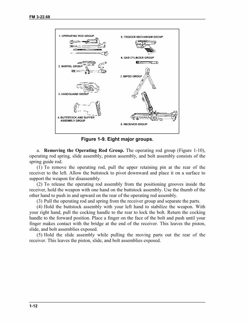
1-6. GENERAL DISASSEMBLYGeneral disassembly is removing and replacing the eight major groups (Figure 1-9,page 1-12). The unit armorer performs detailed disassembly. Disassembly beyond what isexplained in this manual is prohibited, except by ordnance personnel. During generaldisassembly, each part is placed on a clean flat surface such as a table or mat. This aids inassembly in reverse order and avoids the loss of parts. Before disassembly, the bipod legsmust be released from under the receiver and placed into the bipod mode position.
DANGERBE SURE THE BOLT IS IN THE FORWARD POSITIONBEFORE DISASSEMBLY. THE GUIDE ROD CAN CAUSEDEATH OR INJURY IF THE GUIDE SPRING IS RETRACTEDWITH THE BOLT PULLED TO THE REAR.
FM 3-22.68
1-12
Figure 1-9. Eight major groups.
a. Removing the Operating Rod Group. The operating rod group (Figure 1-10),operating rod spring, slide assembly, piston assembly, and bolt assembly consists of thespring guide rod.
(1) To remove the operating rod, pull the upper retaining pin at the rear of thereceiver to the left. Allow the buttstock to pivot downward and place it on a surface tosupport the weapon for disassembly.
(2) To release the operating rod assembly from the positioning grooves inside thereceiver, hold the weapon with one hand on the buttstock assembly. Use the thumb of theother hand to push in and upward on the rear of the operating rod assembly.
(3) Pull the operating rod and spring from the receiver group and separate the parts.(4) Hold the buttstock assembly with your left hand to stabilize the weapon. With
your right hand, pull the cocking handle to the rear to lock the bolt. Return the cockinghandle to the forward position. Place a finger on the face of the bolt and push until yourfinger makes contact with the bridge at the end of the receiver. This leaves the piston,slide, and bolt assemblies exposed.
(5) Hold the slide assembly while pulling the moving parts out the rear of thereceiver. This leaves the piston, slide, and bolt assemblies exposed.
FM 3-22.68
1-13
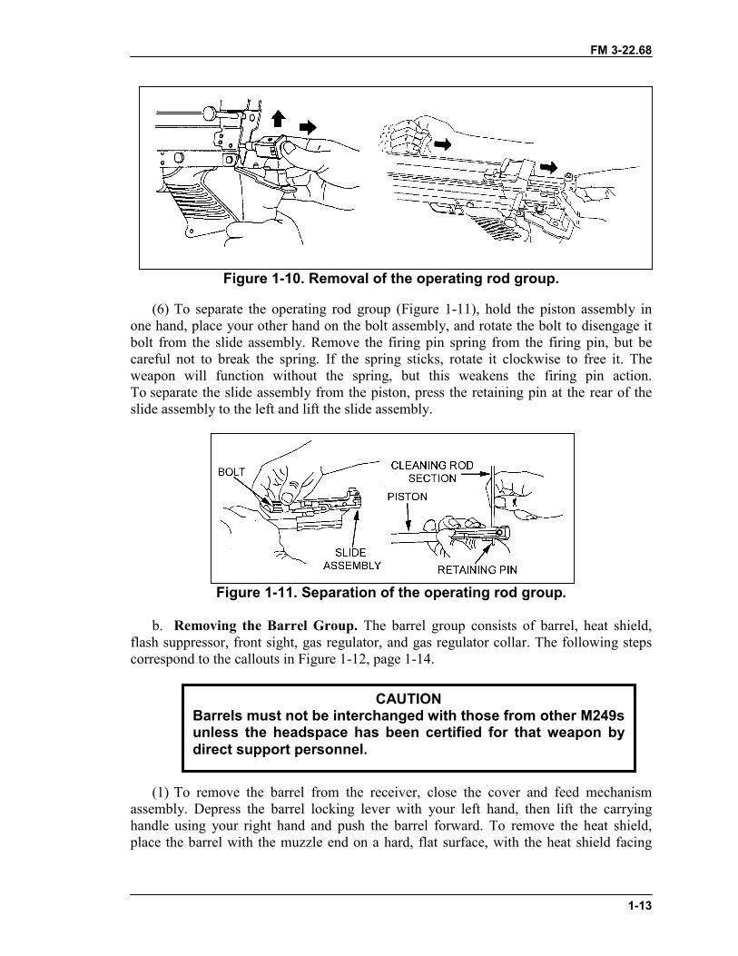
Figure 1-10. Removal of the operating rod group.
(6) To separate the operating rod group (Figure 1-11), hold the piston assembly inone hand, place your other hand on the bolt assembly, and rotate the bolt to disengage itbolt from the slide assembly. Remove the firing pin spring from the firing pin, but becareful not to break the spring. If the spring sticks, rotate it clockwise to free it. Theweapon will function without the spring, but this weakens the firing pin action.To separate the slide assembly from the piston, press the retaining pin at the rear of theslide assembly to the left and lift the slide assembly.
Figure 1-11. Separation of the operating rod group.
b. Removing the Barrel Group. The barrel group consists of barrel, heat shield,flash suppressor, front sight, gas regulator, and gas regulator collar. The following stepscorrespond to the callouts in Figure 1-12, page 1-14.
(1) To remove the barrel from the receiver, close the cover and feed mechanismassembly. Depress the barrel locking lever with your left hand, then lift the carryinghandle using your right hand and push the barrel forward. To remove the heat shield,place the barrel with the muzzle end on a hard, flat surface, with the heat shield facing
CAUTIONBarrels must not be interchanged with those from other M249sunless the headspace has been certified for that weapon bydirect support personnel.
FM 3-22.68
1-14
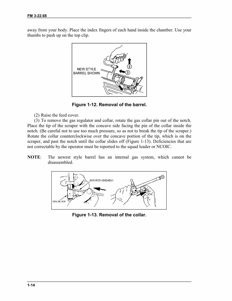
away from your body. Place the index fingers of each hand inside the chamber. Use yourthumbs to push up on the top clip.
Figure 1-12. Removal of the barrel.
(2) Raise the feed cover.(3) To remove the gas regulator and collar, rotate the gas collar pin out of the notch.
Place the tip of the scraper with the concave side facing the pin of the collar inside thenotch. (Be careful not to use too much pressure, so as not to break the tip of the scraper.)Rotate the collar counterclockwise over the concave portion of the tip, which is on thescraper, and past the notch until the collar slides off (Figure 1-13). Deficiencies that arenot correctable by the operator must be reported to the squad leader or NCOIC.
NOTE: The newest style barrel has an internal gas system, which cannot bedisassembled.
Figure 1-13. Removal of the collar.
FM 3-22.68
1-15
(5) To remove the gas regulator (Figure 1-14), separate it from the gas block.
Figure 1-14. Removal of the gas regulator.
c. Removing the Handguard Group. The handguard group (Figure 1-15) consistsof the handguard, handguard retaining pin, and cleaning equipment retaining clip. Pushthe handguard retaining pin to the left using a cartridge or the spring guide rod; then pullthe handguard down.
Figure 1-15. Removal of the handguard.
d. Removing the Buttstock and Buffer Assembly Group. To remove the buttstockand buffer assembly (Figure 1-16, page 1-15), use a cartridge or the spring guide rod topush the lowermost retaining pin on the rear of the receiver to the left. It is a capturedpin; it is not removable. Remove the buttstock and shoulder assembly by pulling themrearward, while supporting the trigger mechanism.
CAUTIONDo not attempt to remove the handguard retaining pincompletely. It is a captured pin.
FM 3-22.68
1-16
Figure 1-16. Removal of the buttstock and buffer assembly.
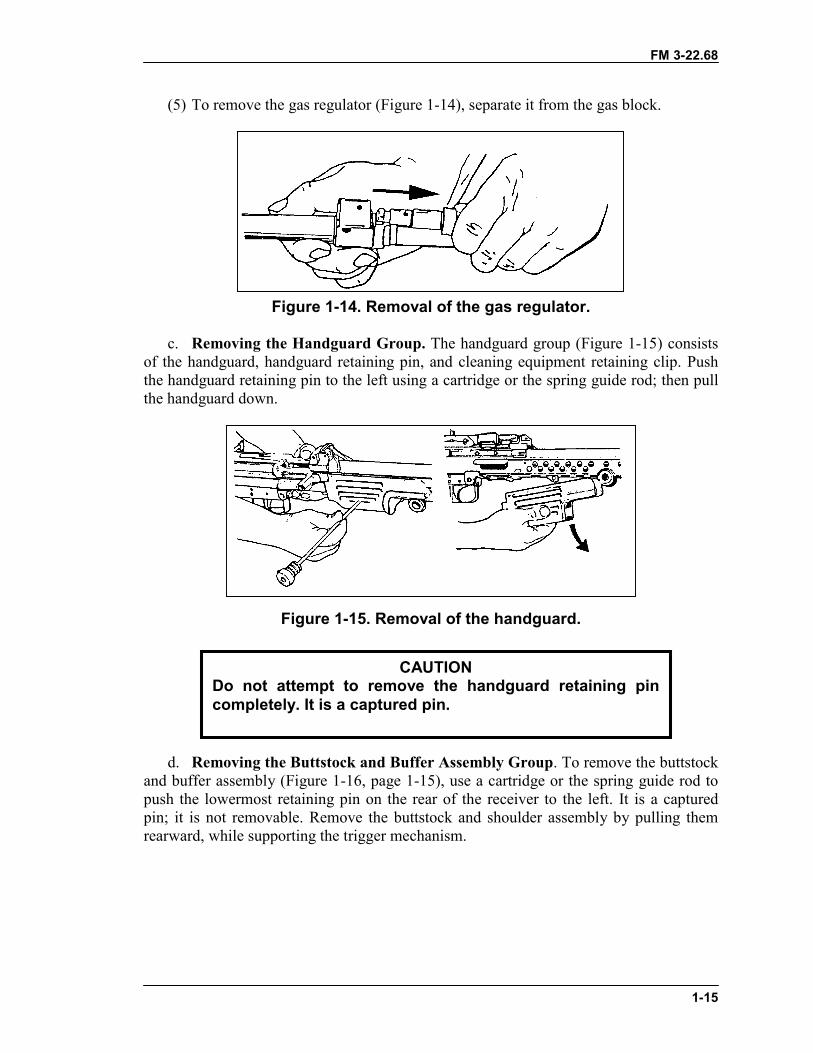
e. Removing the Trigger Mechanism Group. After the release of the support, thetrigger mechanism will automatically be removed because the lowermost retaining pinholds it on.
f. Removing the Gas Cylinder Group. To remove the gas cylinder from thereceiver (Figure 1-17), grasp the gas cylinder at the top of the bipod legs, turn it to the leftor right to release the locking spring, and then pull it away from receiver.
Figure 1-17. Removal of the gas cylinder group.
CAUTIONDo not attempt to remove the upper and lower retaining pinscompletely. They are captured pins.
FM 3-22.68
1-17
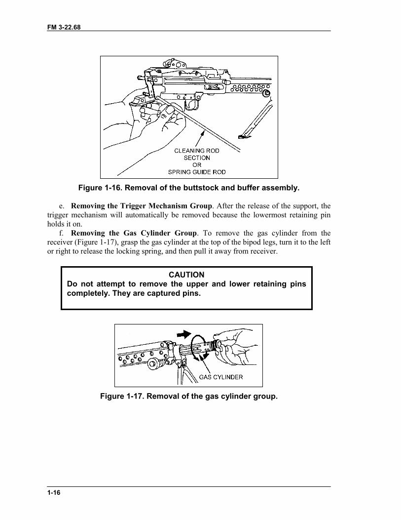
g. Removing the Bipod Group. Once the gas cylinder group is removed, removethe bipod group (Figure 1-18) by pulling it away from the receiver.
Figure 1-18. Removal of the bipod group.
h. Removing the Receiver Group. Once the bipod group is removed, the partremaining is the receiver group, and disassembly is complete.
1-7. INSPECTIONInspection begins with the weapon disassembled in its major groups. Shiny surfaces donot mean the parts are unserviceable. The parts of the weapon and related equipment areinspected. Any broken or missing parts are repaired or replaced IAW TM 9-1005-201-10.The gunner performs preventive maintenance checks and services (PMCS) every 90 days.If the weapon has not been used in 90 days, PMCS is performed as stated in theoperator’s manual. If rust is seen on the weapon, perform PMCS immediately:
a. Operating Rod Group. The operating rod should not be bent, broken, or cracked.The buffer spring should not have breaks. Lug pins should protrude equally on both sidesof the buffer spacer. The operating rod spring should not have kinks or separated strandsor broken strands. It can have a maximum of one break on any one strand.
(1) Check the bolt assembly for visible damage. The cartridge extractor should not becracked or chipped.
(2) Check the slide assembly for visible damage. Check the feed roller for springtension when compressed and to ensure that the pivot slide is locked onto the slideassembly.
(3) Check the firing pin for straightness and cracks. Ensure the tip is completelyrounded.
(4) Ensure the firing pin spring is not crushed or bent. Ensure the beveled end is notstretched.
(5) Check the sear notch on the piston assembly for signs of excessive wear orburring. Slight rotation of the piston on its housing is normal and is not cause forrejection.
b. Barrel Group. The flash suppressor should not be cracked, and it should befastened securely. The front sight post and front sight base must not be bent, cracked, orbroken. Weapons already zeroed should not be adjusted. The heat shield assembly isinspected for damage, cracks, or broken retaining clamps. The gas regulator and collarare checked for cracks or burrs. The barrel is checked for bulges, cracks, bends,obstructions, or pits in the chamber or bore. The gas plug is checked for obstructions,cracks, and bulges. The carrying handle is checked to ensure it is not cracked, broken, or
FM 3-22.68
1-18
missing; that it can be folded under spring pressure to the right and left; and that itremains locked in an upright position.
c. Handguard Group. The handguard should not be cracked or broken. Theretaining clip must be attached to the handguard retaining pin.
d. Buttstock and Buffer Assembly Group. The buttstock is checked for cracks,bends, or breaks; and for missing components. It is checked for linkage and tension onthe buffer rod. The shoulder rest is checked to ensure it is not bent or broken and that itlocks in both positions.
e. Trigger Mechanism Group. The shoulder of the sear should not show excessivewear. The safety should function properly. That is, the sear should move only slightlywhen the safety is on “S” and freely when the safety is on “F”. The sear pin should notprotrude from the trigger mechanism, because, if it does protrude, the trigger mechanismwill not go back in place.
f. Gas Cylinder Group. The gas cylinder should not be cracked, bent, or broken.g. Bipod Group. The bipod group should not be cracked, bent, or broken. The bipod
legs should extend and collapse easily.h. Receiver Group. The cover latch should work properly. All parts inside the cover
assembly should move under spring tension. All spotwelds are checked for cracks. Thecover assembly should remain open without support. The belt-holding pawl must beunder spring tension. The receiver should not be bent or cracked. The cocking handleshould slide freely within its guide and lock in its forward position. The windage andelevation knobs on the rear sight should be movable and legible. The windage scalescrews should not be worn or burred.
1-8. CLEANING, LUBRICATION, AND PREVENTIVE MAINTENANCEThe M249 machine gun should be cleaned immediately after firing. It should bedisassembled into its major groups before cleaning. After it has been cleaned and wipeddry, a thin coat of CLP is applied by rubbing with a cloth. This lubricates and preservesthe exposed metal parts during all normal temperature ranges. When not in use, the M249should be inspected weekly and cleaned and lubricated when necessary.
a. Cleaning. All metal components and surfaces that have been exposed to powderfouling should be cleaned using CLP on a bore-cleaning patch. The same procedure isused to clean the receiver.
(1) Clear and disassemble the weapon.(2) Clean the bore and chamber using CLP and fresh swabs.(3) Clean the gas regulator with the special tool (scraper). Remove all carbon dust.
Do not use CLP on the collar, gas block, or body.(a) Clean the gas-vent hole (Figure 1-19).
CAUTIONWhen using CLP, no other type cleaner can be used. Nevermix CLP with RBC or LSA.
FM 3-22.68
1-19
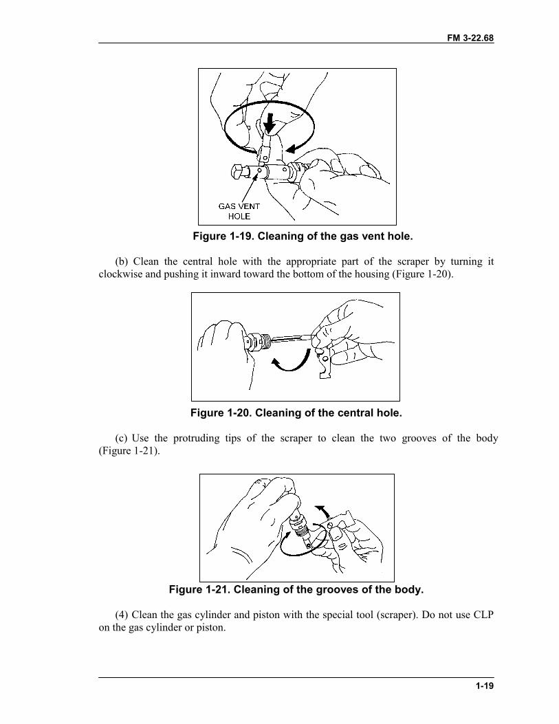
Figure 1-19. Cleaning of the gas vent hole.
(b) Clean the central hole with the appropriate part of the scraper by turning itclockwise and pushing it inward toward the bottom of the housing (Figure 1-20).
Figure 1-20. Cleaning of the central hole.
(c) Use the protruding tips of the scraper to clean the two grooves of the body(Figure 1-21).
Figure 1-21. Cleaning of the grooves of the body.
(4) Clean the gas cylinder and piston with the special tool (scraper). Do not use CLPon the gas cylinder or piston.
FM 3-22.68
1-20
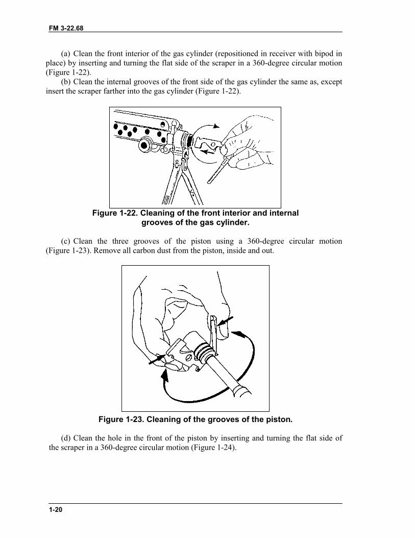
(a) Clean the front interior of the gas cylinder (repositioned in receiver with bipod inplace) by inserting and turning the flat side of the scraper in a 360-degree circular motion(Figure 1-22).
(b) Clean the internal grooves of the front side of the gas cylinder the same as, exceptinsert the scraper farther into the gas cylinder (Figure 1-22).
Figure 1-22. Cleaning of the front interior and internalgrooves of the gas cylinder.
(c) Clean the three grooves of the piston using a 360-degree circular motion(Figure 1-23). Remove all carbon dust from the piston, inside and out.
Figure 1-23. Cleaning of the grooves of the piston.
(d) Clean the hole in the front of the piston by inserting and turning the flat side ofthe scraper in a 360-degree circular motion (Figure 1-24).
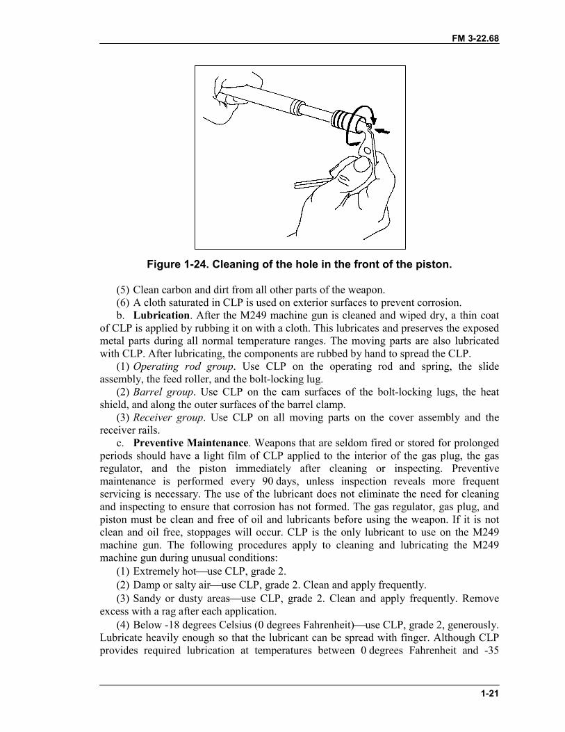
FM 3-22.68
1-21
Figure 1-24. Cleaning of the hole in the front of the piston.
(5) Clean carbon and dirt from all other parts of the weapon.(6) A cloth saturated in CLP is used on exterior surfaces to prevent corrosion.b. Lubrication. After the M249 machine gun is cleaned and wiped dry, a thin coat
of CLP is applied by rubbing it on with a cloth. This lubricates and preserves the exposedmetal parts during all normal temperature ranges. The moving parts are also lubricatedwith CLP. After lubricating, the components are rubbed by hand to spread the CLP.
(1) Operating rod group. Use CLP on the operating rod and spring, the slideassembly, the feed roller, and the bolt-locking lug.
(2) Barrel group. Use CLP on the cam surfaces of the bolt-locking lugs, the heatshield, and along the outer surfaces of the barrel clamp.
(3) Receiver group. Use CLP on all moving parts on the cover assembly and thereceiver rails.
c. Preventive Maintenance. Weapons that are seldom fired or stored for prolongedperiods should have a light film of CLP applied to the interior of the gas plug, the gasregulator, and the piston immediately after cleaning or inspecting. Preventivemaintenance is performed every 90 days, unless inspection reveals more frequentservicing is necessary. The use of the lubricant does not eliminate the need for cleaningand inspecting to ensure that corrosion has not formed. The gas regulator, gas plug, andpiston must be clean and free of oil and lubricants before using the weapon. If it is notclean and oil free, stoppages will occur. CLP is the only lubricant to use on the M249machine gun. The following procedures apply to cleaning and lubricating the M249machine gun during unusual conditions:
(1) Extremely hot�use CLP, grade 2.(2) Damp or salty air�use CLP, grade 2. Clean and apply frequently.(3) Sandy or dusty areas�use CLP, grade 2. Clean and apply frequently. Remove
excess with a rag after each application.(4) Below -18 degrees Celsius (0 degrees Fahrenheit)�use CLP, grade 2, generously.
Lubricate heavily enough so that the lubricant can be spread with finger. Although CLPprovides required lubrication at temperatures between 0 degrees Fahrenheit and -35
FM 3-22.68
1-22
degrees Fahrenheit, it will not flow from a 1/2-ounce bottle at temperatures below 0degrees Fahrenheit.
1-9. GENERAL ASSEMBLYThe M249 machine gun is assembled in reverse order of the disassembly.
a. Replacing the Receiver Group and Bipod Group. Place the bipod group on thereceiver group with the bipod legs open and pointed downward. (See Figure 1-18.)
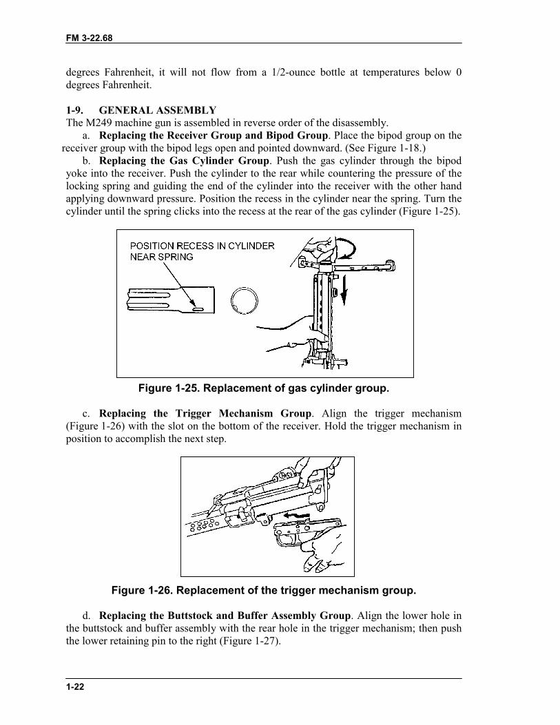
b. Replacing the Gas Cylinder Group. Push the gas cylinder through the bipodyoke into the receiver. Push the cylinder to the rear while countering the pressure of thelocking spring and guiding the end of the cylinder into the receiver with the other handapplying downward pressure. Position the recess in the cylinder near the spring. Turn thecylinder until the spring clicks into the recess at the rear of the gas cylinder (Figure 1-25).
Figure 1-25. Replacement of gas cylinder group.
c. Replacing the Trigger Mechanism Group. Align the trigger mechanism(Figure 1-26) with the slot on the bottom of the receiver. Hold the trigger mechanism inposition to accomplish the next step.
Figure 1-26. Replacement of the trigger mechanism group.
d. Replacing the Buttstock and Buffer Assembly Group. Align the lower hole inthe buttstock and buffer assembly with the rear hole in the trigger mechanism; then pushthe lower retaining pin to the right (Figure 1-27).
FM 3-22.68
1-23
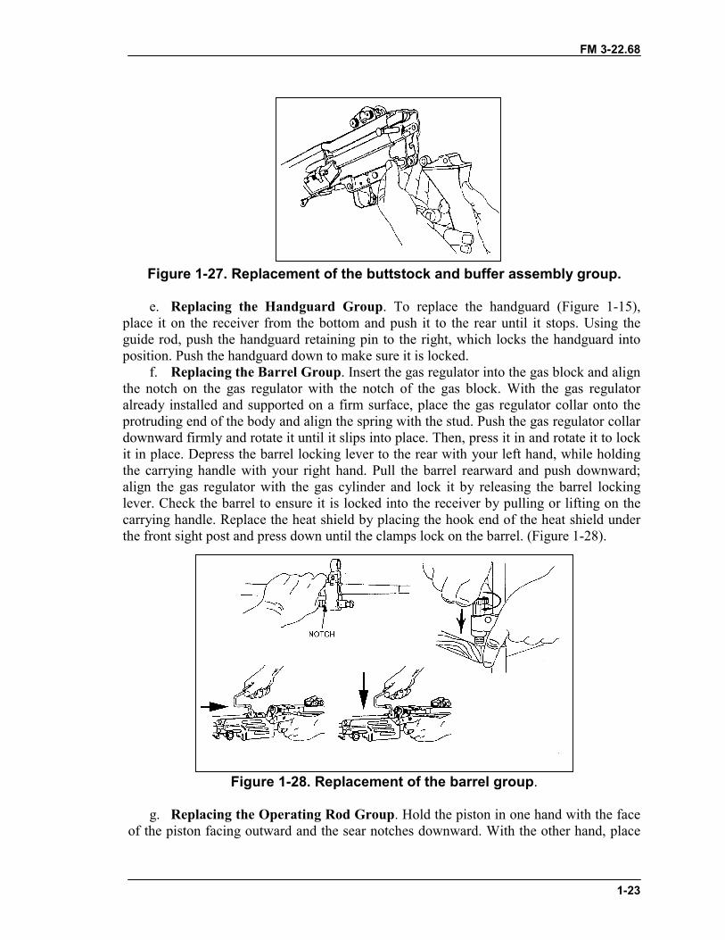
Figure 1-27. Replacement of the buttstock and buffer assembly group.
e. Replacing the Handguard Group. To replace the handguard (Figure 1-15),place it on the receiver from the bottom and push it to the rear until it stops. Using theguide rod, push the handguard retaining pin to the right, which locks the handguard intoposition. Push the handguard down to make sure it is locked.
f. Replacing the Barrel Group. Insert the gas regulator into the gas block and alignthe notch on the gas regulator with the notch of the gas block. With the gas regulatoralready installed and supported on a firm surface, place the gas regulator collar onto theprotruding end of the body and align the spring with the stud. Push the gas regulator collardownward firmly and rotate it until it slips into place. Then, press it in and rotate it to lockit in place. Depress the barrel locking lever to the rear with your left hand, while holdingthe carrying handle with your right hand. Pull the barrel rearward and push downward;align the gas regulator with the gas cylinder and lock it by releasing the barrel lockinglever. Check the barrel to ensure it is locked into the receiver by pulling or lifting on thecarrying handle. Replace the heat shield by placing the hook end of the heat shield underthe front sight post and press down until the clamps lock on the barrel. (Figure 1-28).
Figure 1-28. Replacement of the barrel group.
g. Replacing the Operating Rod Group. Hold the piston in one hand with the faceof the piston facing outward and the sear notches downward. With the other hand, place
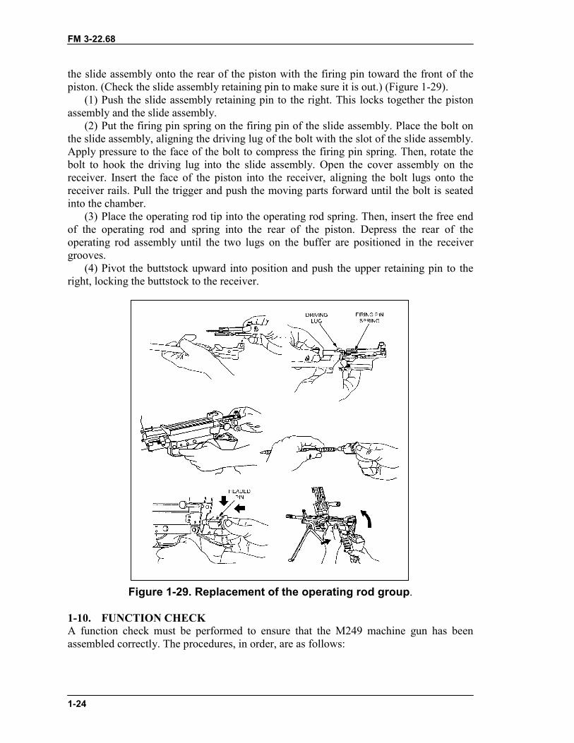
FM 3-22.68
1-24
the slide assembly onto the rear of the piston with the firing pin toward the front of thepiston. (Check the slide assembly retaining pin to make sure it is out.) (Figure 1-29).
(1) Push the slide assembly retaining pin to the right. This locks together the pistonassembly and the slide assembly.
(2) Put the firing pin spring on the firing pin of the slide assembly. Place the bolt onthe slide assembly, aligning the driving lug of the bolt with the slot of the slide assembly.Apply pressure to the face of the bolt to compress the firing pin spring. Then, rotate thebolt to hook the driving lug into the slide assembly. Open the cover assembly on thereceiver. Insert the face of the piston into the receiver, aligning the bolt lugs onto thereceiver rails. Pull the trigger and push the moving parts forward until the bolt is seatedinto the chamber.
(3) Place the operating rod tip into the operating rod spring. Then, insert the free endof the operating rod and spring into the rear of the piston. Depress the rear of theoperating rod assembly until the two lugs on the buffer are positioned in the receivergrooves.
(4) Pivot the buttstock upward into position and push the upper retaining pin to theright, locking the buttstock to the receiver.
Figure 1-29. Replacement of the operating rod group.
1-10. FUNCTION CHECKA function check must be performed to ensure that the M249 machine gun has beenassembled correctly. The procedures, in order, are as follows:
FM 3-22.68
1-25
a. Grasp the cocking handle with the right hand, palm up, and pull the bolt to therear, locking it in place.
b. While continuing to hold the resistance on the cocking handle, use the left hand tomove the safety to the SAFE position.
c. Push the cocking handle forward into the forward lock position.d. Pull the trigger (The weapon should not fire).e. Grasp the cocking handle with the right hand, palm up, and pull and hold it to the
rear.f. Move the safety to the FIRE position.g. While continuing to hold resistance on the cocking handle, use the left hand to
pull the trigger and ease the bolt forward to prevent it from slamming into the chamberarea and damaging the face of the bolt.
h. If the weapon fails the function check, check for missing parts or repeat thereassembly procedures. Before disassembling the weapon, make sure it is positionedwhere the guide rod and spring cannot cause bodily harm if the bolt is locked to the rear.The cover and feed mechanism assembly can be closed with the bolt in either the forwardor the rearward position.
1-11. MAINTENANCE PROCEDURESThere are certain actions that must be taken before, during, and after firing to properlymaintain the M249 machine gun.
a. Before firing�(1) Wipe the bore dry.(2) Inspect the weapon as outlined in the operator's TM.(3) Lubricate the weapon.
b. During firing�(1) Inspect the weapon periodically to ensure that it remains lubricated.(2) When malfunctions or stoppages occur, follow the procedures in Section IV.
c. After firing�(1) Immediately clear and clean the weapon.(2) Every 90 days during inactivity, clean and lubricate the weapon, unless
inspection reveals more frequent servicing is necessary.
1-12. MAINTENANCE DURING NUCLEAR, BIOLOGICAL, CHEMICALCONDITIONSIf the M249 machine gun is contaminated by chemical, biological, or radiological agents,the appropriate action must be taken to reduce exposure and penetration.
a. Chemical. Use towelettes from the M258A1 kit to wipe off the weapon. If theseare not available, wash the weapon with hot, soapy water, and rinse. b. Biological. Use towelettes or hot, soapy water and rinse the weapon as above.
CAUTIONEase the bolt forward to prevent damage to the hardenedsurfaces on the bolt, barrel, and so forth.
FM 3-22.68
1-26
c. Radiological. Brush or wipe the weapon, or wash with water, and rinse. For moredetails, see FM 3-5.
Section III. OPERATION AND FUNCTIONThis section discusses the operation and function of the M249 machine gun. They includeloading, firing, unloading, cycle of functioning, adjusting the sight, and using the bipod.
1-13. OPERATIONThe M249 machine gun operations are loading, firing, unloading, and using beltedammunition or, in an emergency, a 20- or 30-round M16 magazine. The firing operationworks on gas pressure created as a fired round passes through the barrel. The M249 isloaded, fired, unloaded, and cleared from the open-bolt position. The safety must be inthe FIRE position before the bolt can be pulled to the rear. Before using beltedammunition, it must be checked to ensure it is properly linked with the double link or thelink tab at the open end of the box. It must be free of dirt and corrosion. When using amagazine of ammunition, it must be loaded into the magazine well and be free of dirt andcorrosion.
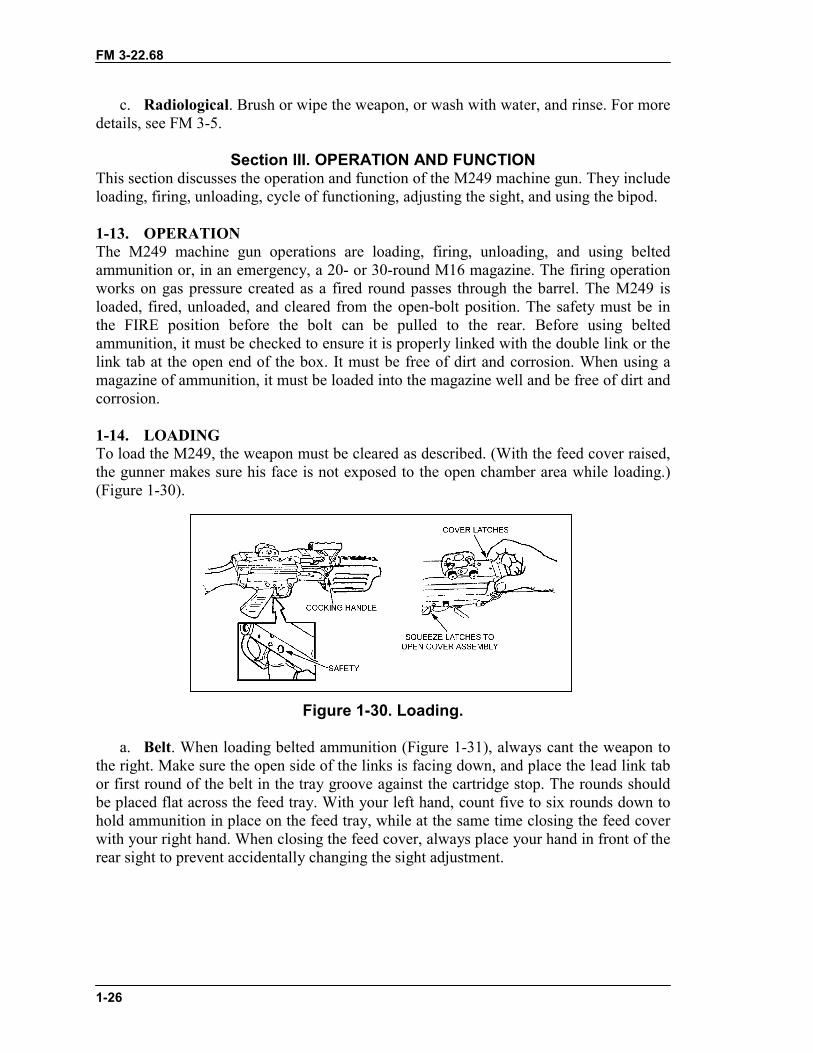
1-14. LOADINGTo load the M249, the weapon must be cleared as described. (With the feed cover raised,the gunner makes sure his face is not exposed to the open chamber area while loading.)(Figure 1-30).
Figure 1-30. Loading.
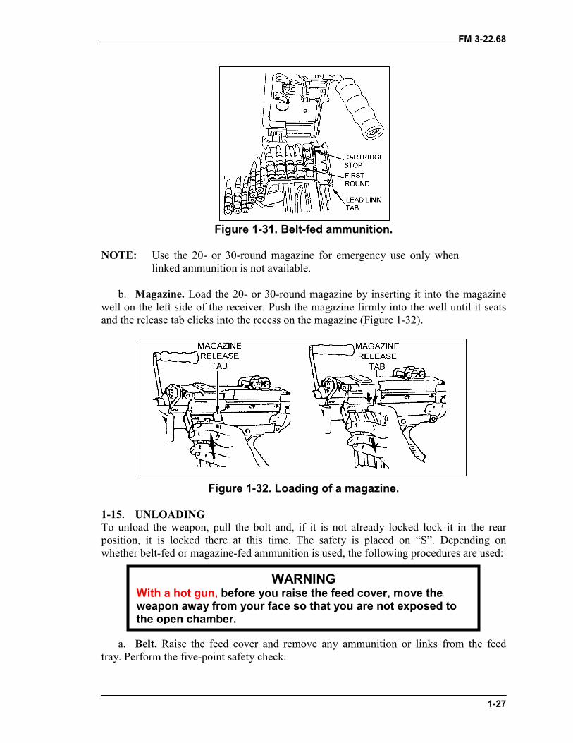
a. Belt. When loading belted ammunition (Figure 1-31), always cant the weapon tothe right. Make sure the open side of the links is facing down, and place the lead link tabor first round of the belt in the tray groove against the cartridge stop. The rounds shouldbe placed flat across the feed tray. With your left hand, count five to six rounds down tohold ammunition in place on the feed tray, while at the same time closing the feed coverwith your right hand. When closing the feed cover, always place your hand in front of therear sight to prevent accidentally changing the sight adjustment.
FM 3-22.68
1-27
Figure 1-31. Belt-fed ammunition.
NOTE: Use the 20- or 30-round magazine for emergency use only whenlinked ammunition is not available.
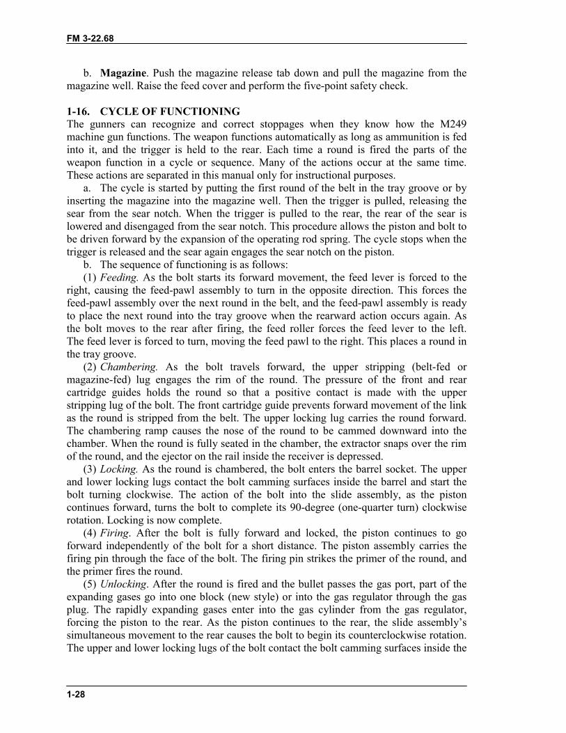
b. Magazine. Load the 20- or 30-round magazine by inserting it into the magazinewell on the left side of the receiver. Push the magazine firmly into the well until it seatsand the release tab clicks into the recess on the magazine (Figure 1-32).
Figure 1-32. Loading of a magazine.
1-15. UNLOADINGTo unload the weapon, pull the bolt and, if it is not already locked lock it in the rearposition, it is locked there at this time. The safety is placed on “S”. Depending onwhether belt-fed or magazine-fed ammunition is used, the following procedures are used:
a. Belt. Raise the feed cover and remove any ammunition or links from the feedtray. Perform the five-point safety check.
WARNINGWith a hot gun, before you raise the feed cover, move theweapon away from your face so that you are not exposed tothe open chamber.
FM 3-22.68
1-28
b. Magazine. Push the magazine release tab down and pull the magazine from themagazine well. Raise the feed cover and perform the five-point safety check.
1-16. CYCLE OF FUNCTIONINGThe gunners can recognize and correct stoppages when they know how the M249machine gun functions. The weapon functions automatically as long as ammunition is fedinto it, and the trigger is held to the rear. Each time a round is fired the parts of theweapon function in a cycle or sequence. Many of the actions occur at the same time.These actions are separated in this manual only for instructional purposes.
a. The cycle is started by putting the first round of the belt in the tray groove or byinserting the magazine into the magazine well. Then the trigger is pulled, releasing thesear from the sear notch. When the trigger is pulled to the rear, the rear of the sear islowered and disengaged from the sear notch. This procedure allows the piston and bolt tobe driven forward by the expansion of the operating rod spring. The cycle stops when thetrigger is released and the sear again engages the sear notch on the piston.
b. The sequence of functioning is as follows:(1) Feeding. As the bolt starts its forward movement, the feed lever is forced to the
right, causing the feed-pawl assembly to turn in the opposite direction. This forces thefeed-pawl assembly over the next round in the belt, and the feed-pawl assembly is readyto place the next round into the tray groove when the rearward action occurs again. Asthe bolt moves to the rear after firing, the feed roller forces the feed lever to the left.The feed lever is forced to turn, moving the feed pawl to the right. This places a round inthe tray groove.
(2) Chambering. As the bolt travels forward, the upper stripping (belt-fed ormagazine-fed) lug engages the rim of the round. The pressure of the front and rearcartridge guides holds the round so that a positive contact is made with the upperstripping lug of the bolt. The front cartridge guide prevents forward movement of the linkas the round is stripped from the belt. The upper locking lug carries the round forward.The chambering ramp causes the nose of the round to be cammed downward into thechamber. When the round is fully seated in the chamber, the extractor snaps over the rimof the round, and the ejector on the rail inside the receiver is depressed.
(3) Locking. As the round is chambered, the bolt enters the barrel socket. The upperand lower locking lugs contact the bolt camming surfaces inside the barrel and start thebolt turning clockwise. The action of the bolt into the slide assembly, as the pistoncontinues forward, turns the bolt to complete its 90-degree (one-quarter turn) clockwiserotation. Locking is now complete.
(4) Firing. After the bolt is fully forward and locked, the piston continues to goforward independently of the bolt for a short distance. The piston assembly carries thefiring pin through the face of the bolt. The firing pin strikes the primer of the round, andthe primer fires the round.
(5) Unlocking. After the round is fired and the bullet passes the gas port, part of theexpanding gases go into one block (new style) or into the gas regulator through the gasplug. The rapidly expanding gases enter into the gas cylinder from the gas regulator,forcing the piston to the rear. As the piston continues to the rear, the slide assembly’ssimultaneous movement to the rear causes the bolt to begin its counterclockwise rotation.The upper and lower locking lugs of the bolt contact the bolt camming surfaces inside the
FM 3-22.68
1-29
barrel socket and, as the bolt continues toward the rear, it completes a one-quarter turncounterclockwise. The rotation and movement to the rear unlocks the bolt from the barrelsocket.
(6) Extracting. Extracting begins during the unlocking cycle. The rotation of the boltloosens the cartridge case in the chamber. As the piston and bolt move to the rear, theextractor pulls the cartridge case from the chamber.
(7) Ejecting. As the cartridge case is pulled from the chamber, the bolt passes by theejector. This procedure causes the ejector clip to expand, forcing the ejector to push theexpended cartridge. The extractor grips the right side of the cartridge and causes it to spinfrom the weapon as it reaches the ejection port. The empty belt links are forced out of thelink ejection port as the rearward movement of the bolt causes the next round to bepositioned in the tray groove.
(8) Cocking. The piston assembly acts against the firing pin, pulling the firing pinfrom the primer of the spent cartridge case. The action of the piston assembly, continuingto the rear with the firing pin, releases the compression of the firing pin spring. As longas the trigger is held to the rear, the M249 will continue to complete the eight steps offunctioning automatically. When the trigger is released and the sear again engages thesear notch, the cycle of functioning is stopped and the weapon is cocked. To preventundue wear to the sear and sear notch, the automatic rifleman must hold the trigger firmlyto the rear during firing.
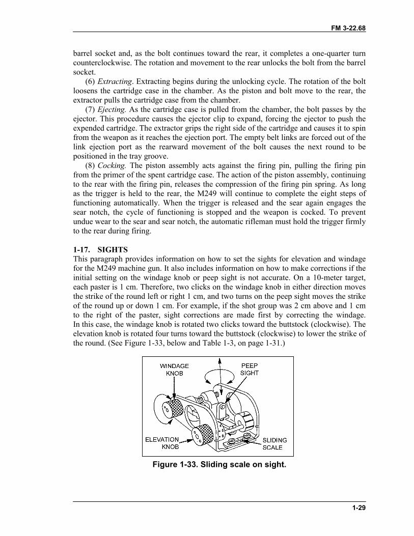
1-17. SIGHTSThis paragraph provides information on how to set the sights for elevation and windagefor the M249 machine gun. It also includes information on how to make corrections if theinitial setting on the windage knob or peep sight is not accurate. On a 10-meter target,each paster is 1 cm. Therefore, two clicks on the windage knob in either direction movesthe strike of the round left or right 1 cm, and two turns on the peep sight moves the strikeof the round up or down 1 cm. For example, if the shot group was 2 cm above and 1 cmto the right of the paster, sight corrections are made first by correcting the windage.In this case, the windage knob is rotated two clicks toward the buttstock (clockwise). Theelevation knob is rotated four turns toward the buttstock (clockwise) to lower the strike ofthe round. (See Figure 1-33, below and Table 1-3, on page 1-31.)
Figure 1-33. Sliding scale on sight.
FM 3-22.68
1-30
a. Elevation. Adjustments for elevation (range) require the automatic rifleman toturn the elevation knob (closest to the buttstock) on the rear sight to the desired rangesetting. Range settings are graduated increments from 300 to 1,000 meters. Even-numbered settings are on the left side of the scale wheel and are numbered 4, 6, 8, 10,which represent 400, 600, 800, and 1,000 meters, respectively. Odd-numbered settingsare on the right side of the scale wheel and marked with the number 3 and three indexlines, which represent 300, 500, 700, and 900 meters, respectively. Rotation of theelevation knob toward the muzzle (counterclockwise) increases the range, while rotationtoward the buttstock (clockwise) decreases the range. Fine adjustments, like zeroing, aremade by adjusting the peep sight. Each 180-degree turn equals a half-mil change inelevation, which equals a half-cm change in impact at a range of 10 meters. Clockwise(to the right) rotations decrease elevation, while counterclockwise (to the left) rotationsincrease elevation. The peep sight can be turned nine 180-degree turns from top tobottom. To make the peep sight easier to grasp, the elevation knob is turned to its highestpoint (1,000 meters). The appropriate adjustment is made for the peep sight, and then thesight is returned to the desired range. Whenever readjusting the range, the point of aim isnever changed. The point of aim is the center base of the target.
b. Windage. Adjustments for windage are made by traversing the rear sight right andleft along the sliding scale. The sliding scale is marked or graduated with index lines. Eachindex line is equal to a half-mil change in direction or a half-cm change of impact at10 meters. Rotation of the windage knob (closest to the muzzle end) toward the muzzle(counterclockwise) moves the rear sight aperture right, which moves the strike of therounds right. Rotation toward the buttstock (clockwise) moves the aperture left, whichmoves the strike of the rounds left.
c. 10-Meter Zero, Setting of the Sights (Mechanical Zero). The gunner indexes orplaces the elevation knob on a range of 700 meters. He centers the rear peep sight byrotating it clockwise (right) as far as it will go, then rotating counterclockwise (left) fiveclicks or half-turns. He rotates the windage knob toward the muzzle until the peep sight iscompletely to the right, then rotates the windage knob toward the buttstock twelve clicksto the left. This places the peep sight in the approximate center of the sight. Each sightmay vary as to how many clicks are needed. To check the sight, the gunner starts with thesight all the way to the right and, while counting the clicks, rotates the windage knobuntil it stops on the left side. He divides the clicks by two. If the click is an unevennumber, he rounds it up. To center the sight, he rotates the windage knob toward thecenter (right) while counting the appropriate number of clicks. He adjusts the slidingscale at the rear of the sight to center the large index line under the zeroed windage markon the sight. Two threads should be showing on the front sight post. If more or less areshowing, the gunner turns in the weapon for maintenance.
FM 3-22.68
1-31
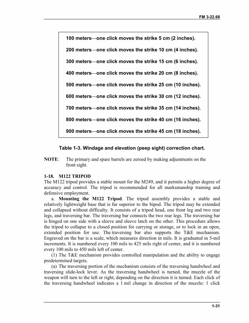
100 meters�one click moves the strike 5 cm (2 inches).
200 meters�one click moves the strike 10 cm (4 inches).
300 meters�one click moves the strike 15 cm (6 inches).
400 meters�one click moves the strike 20 cm (8 inches).
500 meters�one click moves the strike 25 cm (10 inches).
600 meters�one click moves the strike 30 cm (12 inches).
700 meters�one click moves the strike 35 cm (14 inches).
800 meters�one click moves the strike 40 cm (16 inches).
900 meters�one click moves the strike 45 cm (18 inches).
Table 1-3. Windage and elevation (peep sight) correction chart.
NOTE: The primary and spare barrels are zeroed by making adjustments on thefront sight.
1-18. M122 TRIPODThe M122 tripod provides a stable mount for the M249, and it permits a higher degree ofaccuracy and control. The tripod is recommended for all marksmanship training anddefensive employment.
a. Mounting the M122 Tripod. The tripod assembly provides a stable andrelatively lightweight base that is far superior to the bipod. The tripod may be extendedand collapsed without difficulty. It consists of a tripod head, one front leg and two rearlegs, and traversing bar. The traversing bar connects the two rear legs. The traversing baris hinged on one side with a sleeve and sleeve latch on the other. This procedure allowsthe tripod to collapse to a closed position for carrying or storage, or to lock in an open,extended position for use. The traversing bar also supports the T&E mechanism.Engraved on the bar is a scale, which measures direction in mils. It is graduated in 5-milincrements. It is numbered every 100 mils to 425 mils right of center, and it is numberedevery 100 mils to 450 mils left of center.
(1) The T&E mechanism provides controlled manipulation and the ability to engagepredetermined targets.
(a) The traversing portion of the mechanism consists of the traversing handwheel andtraversing slide-lock lever. As the traversing handwheel is turned, the muzzle of theweapon will turn to the left or right, depending on the direction it is turned. Each click ofthe traversing handwheel indicates a 1 mil change in direction of the muzzle: 1 click
FM 3-22.68
1-32
equals 1 mil. There is a total of 100 mils traverse (50 mils right and 50 mils left ofcenter).
(b) The elevating portion of the mechanism consists only of the elevating handwheel.The elevating handwheel has a mil-click device built into it (1 click equals 1 mil).Engraved into the handwheel is a scale divided into 5-mil divisions and 1-milsubdivisions, for a total of 50 mils increments. There are 200 mils above and 200 milsbelow the zero mark ,for a total of 400 mils in elevation change. Elevation readings aretaken in two parts. First, the major reading is taken from the elevation screw plate. Thesecond, minor reading is from the handwheel. The two readings are separated by a slash(“/”) when they are recorded.
(c) The traversing slide-lock lever allows rapid lateral adjustments along thetraversing bar. Direction readings are taken from the scale on the traversing bar, using theleft side of the traversing slide as an index. The direction of the reading comes from theposition of the muzzle, not the position of the slide.
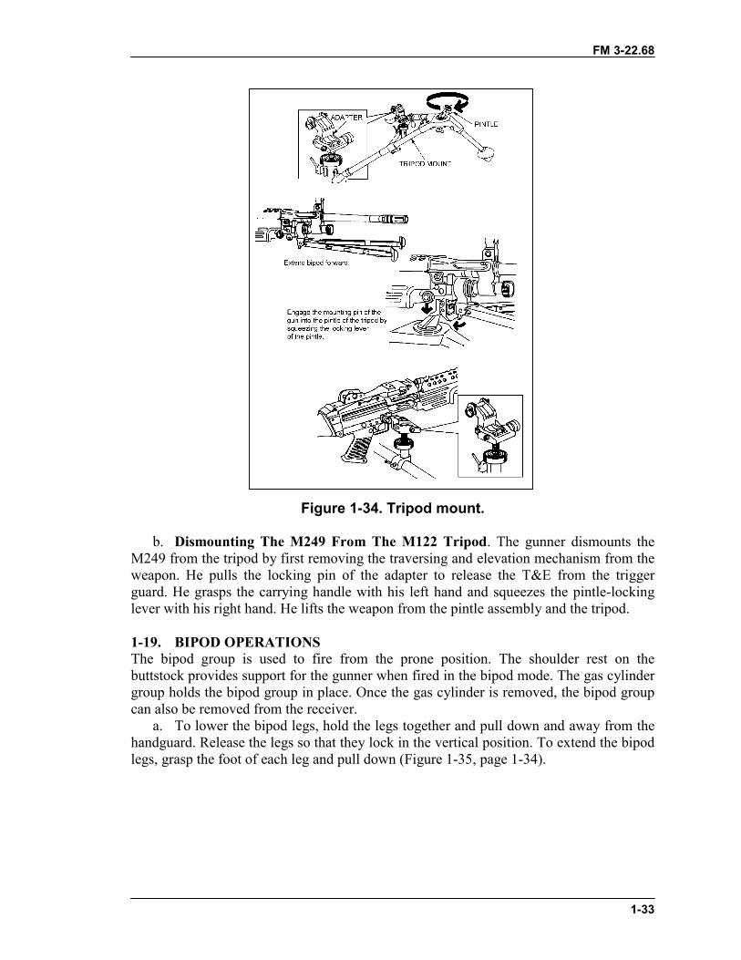
(2) To set up the tripod, unfold the front leg and spread the rear legs until the leg lockengages. Insert the pintle assembly and rotate the pintle lock-release cam to lock. Ensurethat the locking lever of the pintle is facing forward toward the front leg (Figure 1-34).
(3) Attach the traversing and elevating mechanism (which requires a special adapter).Ensure that the adapter pin is to the right and the opening between it is to the rear. Centerthe elevating and traversing handwheels. To do this, he rotates the elevation handwheeluntil about 1-1/2 inches (two fingers) are visible on the upper elevating screw; he rotatesthe traversing slide until about two fingers are visible on the lower elevating screw.He rotates the traversing handwheel towards his body as far as it will go, then turns itaway two complete revolutions. He checks the traversing handwheel scale to ensure the“0” on the scale is aligned with the “0” index line before and after the two revolutions.The T&E is now roughly centered. At night, he positions the traversing mechanism byturning the traversing handwheel toward his body as far as it will go, and then turning itaway 50 clicks (two revolutions) (Figure 1-34).
(4) With the T&E roughly centered, he lowers the traversing slide on to the traversingbar with the locking lever to the rear, and the traversing handwheel to the left, andsecures it by turning the locking lever clockwise (Figure 1-34).
(5) The weapon attaches to the M122 tripod. First, he extends the bipod legs forward.Then, he engages the mounting pins (Located between the front of the handguard and thebipod legs) of the M249 into the pintle of the tripod by squeezing the locking lever of thepintle. He lowers the rear of the weapon so that the hole above the trigger guard can beengaged with the locking pin of the T&E adapter. He aligns the hole with the pin of theadapter and pushes the pin from right to left to secure the M249 to the M122 tripod(Figure 1-34).
(6) After the M249 is attached and secured to the tripod, the gunner must attach aspecial ammunition adapter to the M249. He inserts the adapter into the magazine well,as if inserting a magazine. This procedure allows the gunner to use the 200-round drumof ammunition (Figure 1-34).
FM 3-22.68
1-33
Figure 1-34. Tripod mount.
b. Dismounting The M249 From The M122 Tripod. The gunner dismounts theM249 from the tripod by first removing the traversing and elevation mechanism from theweapon. He pulls the locking pin of the adapter to release the T&E from the triggerguard. He grasps the carrying handle with his left hand and squeezes the pintle-lockinglever with his right hand. He lifts the weapon from the pintle assembly and the tripod.
1-19. BIPOD OPERATIONSThe bipod group is used to fire from the prone position. The shoulder rest on thebuttstock provides support for the gunner when fired in the bipod mode. The gas cylindergroup holds the bipod group in place. Once the gas cylinder is removed, the bipod groupcan also be removed from the receiver.
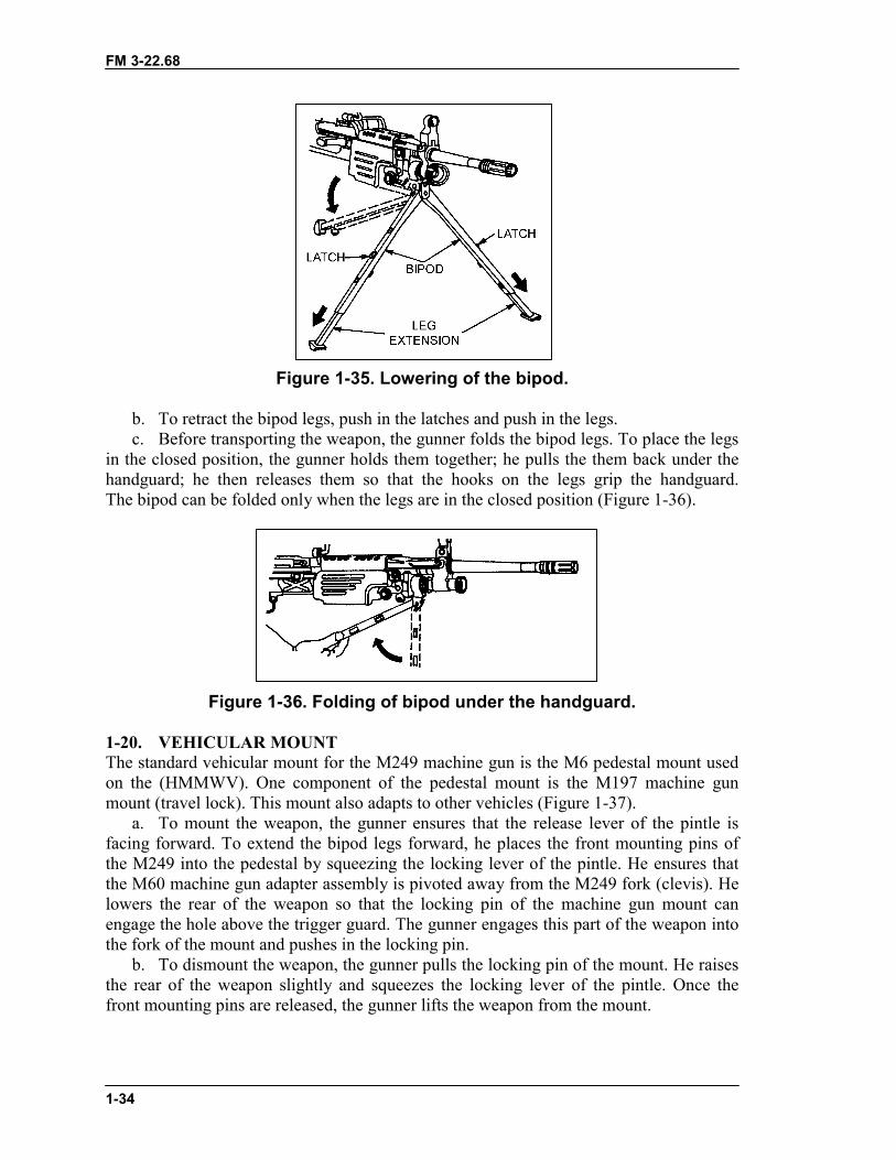
a. To lower the bipod legs, hold the legs together and pull down and away from thehandguard. Release the legs so that they lock in the vertical position. To extend the bipodlegs, grasp the foot of each leg and pull down (Figure 1-35, page 1-34).
FM 3-22.68
1-34
Figure 1-35. Lowering of the bipod.
b. To retract the bipod legs, push in the latches and push in the legs.c. Before transporting the weapon, the gunner folds the bipod legs. To place the legs
in the closed position, the gunner holds them together; he pulls the them back under thehandguard; he then releases them so that the hooks on the legs grip the handguard.The bipod can be folded only when the legs are in the closed position (Figure 1-36).
Figure 1-36. Folding of bipod under the handguard.
1-20. VEHICULAR MOUNTThe standard vehicular mount for the M249 machine gun is the M6 pedestal mount usedon the (HMMWV). One component of the pedestal mount is the M197 machine gunmount (travel lock). This mount also adapts to other vehicles (Figure 1-37).
a. To mount the weapon, the gunner ensures that the release lever of the pintle isfacing forward. To extend the bipod legs forward, he places the front mounting pins ofthe M249 into the pedestal by squeezing the locking lever of the pintle. He ensures thatthe M60 machine gun adapter assembly is pivoted away from the M249 fork (clevis). Helowers the rear of the weapon so that the locking pin of the machine gun mount canengage the hole above the trigger guard. The gunner engages this part of the weapon intothe fork of the mount and pushes in the locking pin.
b. To dismount the weapon, the gunner pulls the locking pin of the mount. He raisesthe rear of the weapon slightly and squeezes the locking lever of the pintle. Once thefront mounting pins are released, the gunner lifts the weapon from the mount.
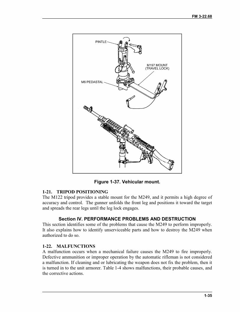
FM 3-22.68
1-35
Figure 1-37. Vehicular mount.
1-21. TRIPOD POSITIONINGThe M122 tripod provides a stable mount for the M249, and it permits a high degree ofaccuracy and control. The gunner unfolds the front leg and positions it toward the targetand spreads the rear legs until the leg lock engages.
Section IV. PERFORMANCE PROBLEMS AND DESTRUCTIONThis section identifies some of the problems that cause the M249 to perform improperly.It also explains how to identify unserviceable parts and how to destroy the M249 whenauthorized to do so.
1-22. MALFUNCTIONSA malfunction occurs when a mechanical failure causes the M249 to fire improperly.Defective ammunition or improper operation by the automatic rifleman is not considereda malfunction. If cleaning and or lubricating the weapon does not fix the problem, then itis turned in to the unit armorer. Table 1-4 shows malfunctions, their probable causes, andthe corrective actions.
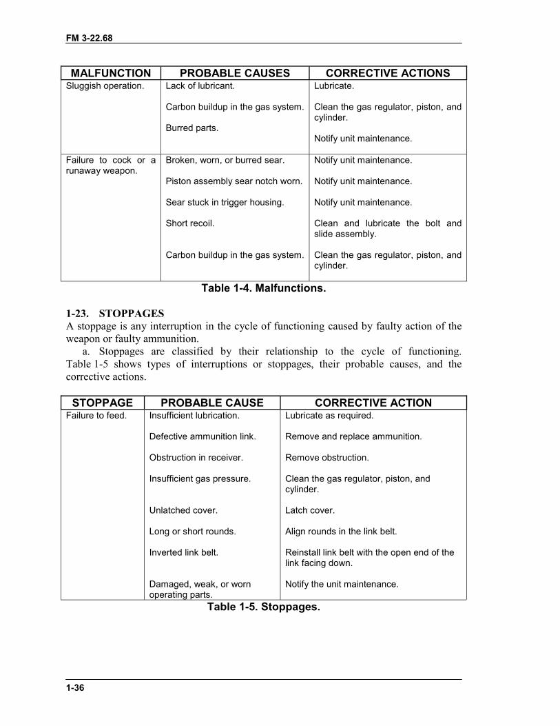
FM 3-22.68
1-36
MALFUNCTION PROBABLE CAUSES CORRECTIVE ACTIONSSluggish operation. Lack of lubricant.
Carbon buildup in the gas system.
Burred parts.
Lubricate.
Clean the gas regulator, piston, andcylinder.
Notify unit maintenance.
Failure to cock or arunaway weapon.
Broken, worn, or burred sear.
Piston assembly sear notch worn.
Sear stuck in trigger housing.
Short recoil.
Carbon buildup in the gas system.
Notify unit maintenance.
Notify unit maintenance.
Notify unit maintenance.
Clean and lubricate the bolt andslide assembly.
Clean the gas regulator, piston, andcylinder.
Table 1-4. Malfunctions.
1-23. STOPPAGESA stoppage is any interruption in the cycle of functioning caused by faulty action of theweapon or faulty ammunition.
a. Stoppages are classified by their relationship to the cycle of functioning.Table 1-5 shows types of interruptions or stoppages, their probable causes, and thecorrective actions.
STOPPAGE PROBABLE CAUSE CORRECTIVE ACTIONFailure to feed. Insufficient lubrication.
Defective ammunition link.
Obstruction in receiver.
Insufficient gas pressure.
Unlatched cover.
Long or short rounds.
Inverted link belt.
Damaged, weak, or wornoperating parts.
Lubricate as required.
Remove and replace ammunition.
Remove obstruction.
Clean the gas regulator, piston, andcylinder.
Latch cover.
Align rounds in the link belt.
Reinstall link belt with the open end of thelink facing down.
Notify the unit maintenance.
Table 1-5. Stoppages.
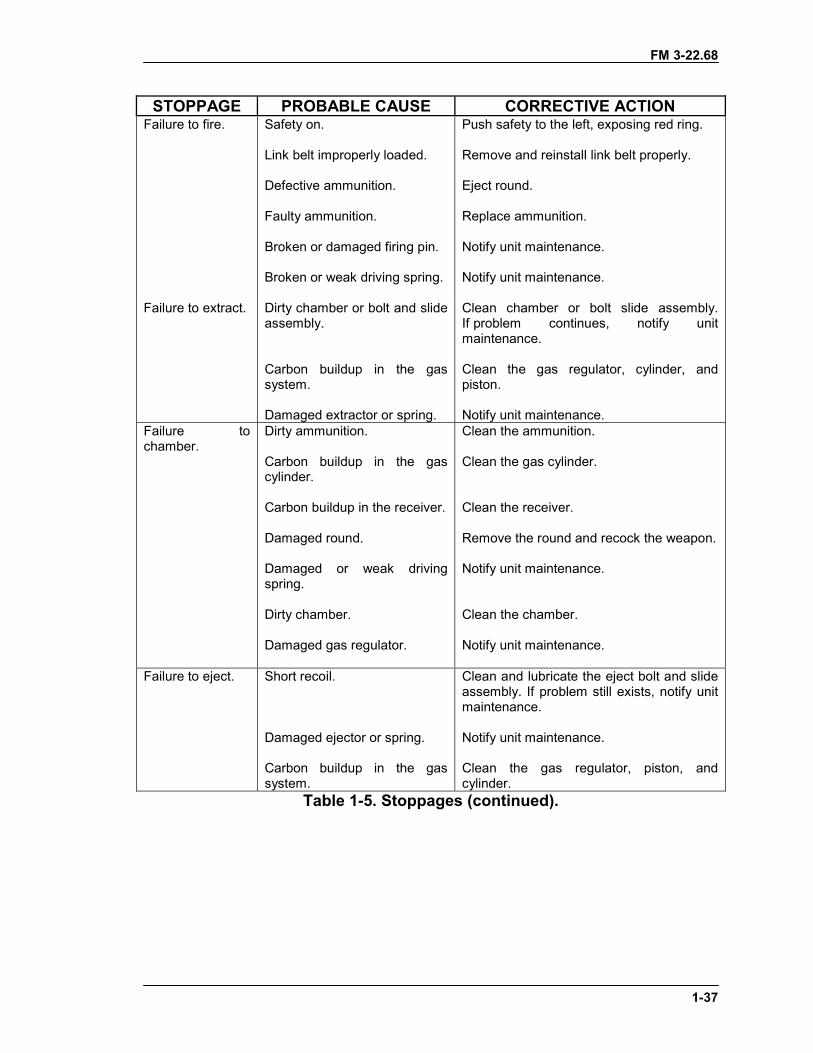
FM 3-22.68
1-37
STOPPAGE PROBABLE CAUSE CORRECTIVE ACTIONFailure to fire. Safety on.
Link belt improperly loaded.
Defective ammunition.
Faulty ammunition.
Broken or damaged firing pin.
Broken or weak driving spring.
Push safety to the left, exposing red ring.
Remove and reinstall link belt properly.
Eject round.
Replace ammunition.
Notify unit maintenance.
Notify unit maintenance.
Failure to extract. Dirty chamber or bolt and slideassembly.
Carbon buildup in the gassystem.
Damaged extractor or spring.
Clean chamber or bolt slide assembly.If problem continues, notify unitmaintenance.
Clean the gas regulator, cylinder, andpiston.
Notify unit maintenance.Failure tochamber.
Dirty ammunition.
Carbon buildup in the gascylinder.
Carbon buildup in the receiver.
Damaged round.
Damaged or weak drivingspring.
Dirty chamber.
Damaged gas regulator.
Clean the ammunition.
Clean the gas cylinder.
Clean the receiver.
Remove the round and recock the weapon.
Notify unit maintenance.
Clean the chamber.
Notify unit maintenance.
Failure to eject. Short recoil.
Damaged ejector or spring.
Carbon buildup in the gassystem.
Clean and lubricate the eject bolt and slideassembly. If problem still exists, notify unitmaintenance.
Notify unit maintenance.
Clean the gas regulator, piston, andcylinder.
Table 1-5. Stoppages (continued).
FM 3-22.68
1-38
b. If a round is in the chamber (this means any part of the round, ranging from thetip of the bullet to the rim) when applying immediate or remedial action on a cold or hotgun. The gunner removes the ammunition from the feed tray only, then closes the coverand attempts to fire. If the weapon fires, he reloads and continues firing. If it does notfire, he clears the weapon (removes the round using a clearing rod, with the coverclosed). He does not use anything other than a cleaning rod. Then, he inspects weaponand ammunition.
1-24. IMMEDIATE ACTIONImmediate action is action taken to reduce a stoppage without looking for the cause.Immediate action should be taken in the event of a misfire or a cook off. A misfire is thefailure of a chambered round to fire. Such failure can be due to an ammunition defect orfaulty firing mechanism. A cook off is the firing of a round due to the heat of a hot barreland not to the firing mechanism. Cook offs can be avoided by applying immediate actionwithin 10 seconds of a failure to fire. The gunner keeps the M249 on his shoulder whileperforming immediate action procedures. If the M249 stops firing, he takes the followingimmediate actions. An effective memory aid is POPP, which stands for Pull, Observe,Push, and Press:
a. Pull and lock the cocking handle to the rear while observing the ejection port tosee if a cartridge case, belt link, or round is ejected. Ensure that the bolt remains to therear to prevent double feeding if a round or cartridge case is not ejected.
b. If a cartridge case, belt link, or round is ejected, push the cocking handle to itsforward position, take aim on the target, and press the trigger. If the weapon does not fire,take remedial action. If a cartridge case, belt link, or round is not ejected, takeremedial action.
DANGERIF NOTHING IS EJECTED AND THE WEAPON IS HOT (200 ORMORE ROUNDS FIRED IN LESS THAN 2 MINUTES), DO NOTOPEN THE COVER. PUSH THE SAFETY TO THE RIGHT (REDRING NOT VISIBLE), WHICH PLACES THE WEAPON ON SAFE.KEEP THE WEAPON POINTED DOWNRANGE FOR 15 MINUTES,THEN CLEAR THE WEAPON. BE CAREFUL CLEARING THEWEAPON WHEN THE BARREL IS HOT; A ROUND MAY FIRE(COOK OFF) DUE TO THE BARREL’S HEAT INSTEAD OF THEFIRING MECHANISM. DURING TRAINING OR ON A FIRINGRANGE, AFTER THE WEAPON HAS FIRED 200 ROUNDS, THEBARREL IS CONSIDERED “HOT.”
� DURING COMBAT, WAIT 5 SECONDS (BECAUSE OF THEPOSSIBILITY OF A HANGFIRE) BEFORE APPLYINGIMMEDIATE ACTION OR REMEDIAL ACTION.
� DURING TRAINING, WAIT 15 MINUTES BEFORECLEARING A HOT WEAPON AND APPLYING IMMEDIATEOR REMEDIAL ACTION.
FM 3-22.68
1-39
1-25. REMEDIAL ACTIONRemedial action is any action taken to determine the cause of a stoppage and to restore
the weapon to an operational condition. This action is taken only after immediate actiondoes not remedy the problem.
a. Cold Weapon Procedures. When a stoppage occurs with a cold weapon, and ifimmediate action has failed, use the following procedures:
(1) While the weapon is on your shoulder, grasp the cocking handle with the righthand, palm up; pull the cocking handle to the rear, locking the bolt. While holding theresistance on the cocking handle, move the safety to SAFE and return the cocking handle.
(2) Place the weapon on the ground or away from your face. Open the feed cover andperform the five-point safety check. Reload and continue to fire.
(3) If the weapon does not fire, clear the weapon and inspect it and the ammunition.b. Hot Weapon Procedures. If the stoppage occurs with a hot weapon (200 or more
rounds in less than 2 minutes, or as noted previously for training), move the safety toSAFE, wait 5 seconds (during training, let the weapon cool for 15 minutes), and use thesame procedures as outlined for cold weapon procedures.
c. Jammed Cocking Handle. If a stoppage occurs, and if the cocking handle cannotbe pulled to the rear by hand (the bolt may be fully forward and locked or only partiallyforward), the gunner takes the following steps:
(1) Tries once again to pull the cocking handle by hand.
(2) If the weapon is hot enough to cause a cook off, moves all Soldiers a safe distancefrom the weapon and keeps them away for 15 minutes.
(3) After the gun has cooled, opens the cover and disassembles the gun. Ensuresrearward pressure is kept on the cocking handle until the buffer is removed. (Theassistant gunner helps the gunner do this.)
(4) Removes the round or fired cartridge. Uses cleaning rod or ruptured cartridgeextractor if necessary.
(a) In a training situation, after completing the remedial action procedures does notfire the gun until an ordnance specialist has conducted an inspection.
(b) In a combat situation, after the stoppage has been corrected, the gunner changesthe barrel and tries to fire. If the weapon fails to function properly, he sends it to the unitarmorer.
1-26. DESTRUCTION PROCEDURESDestruction of any military weapon is only authorized as a last resort to prevent enemycapture or use. This paragraph discusses the field-expedient means of this destruction; itdoes not replace published policies. In combat situations, the commander has theauthority to destroy weapons, but he must report this destruction through channels.
CAUTIONDo not try to force the cocking handle to the rear with yourfoot or a heavy object. This could damage the weapon.

FM 3-22.68
1-40
a. Disassemble the weapon as completely as time permits. Use the barrel to destroythe bolt, operating rod group, bipod, sights (rear and front), and receiver.
b. Bury the disassembled weapon or dump the parts into a stream, a sump,or a latrine.
c. Burn the weapon by placing an incendiary grenade on the receiver group over thebolt (with the cover feed mechanism assembly resting on the grenade) and detonatingthe grenade.
FM 3-22.68
2-1
CHAPTER 2M60 MACHINE GUN
The 7.62-mm M60 machine gun supports the rifleman in offense anddefense. It provides the heavy volume of close and continuous fire therifleman needs to accomplish his mission. The M60 is used to engagetargets beyond the range of individual weapons, with controlled andaccurate fire. The long-range, close defensive, and final protective firesdelivered by the M60 form an integral part of a unit's defensive fires. Thischapter describes the weapon and the types of ammunition it uses in detailand provides a table of general data.
Section I. DESCRIPTION AND COMPONENTSThis section describes the M60 machine gun and its components and purposes,ammunition, and blank firing adapters, and how to install them. The primary use of theM60 is to support the rifleman in both offense and defense. It provides the heavy volumeof close and continuous fire he needs to accomplish the mission. It can engage targetsbeyond the capability of individual weapons with controlled, accurate bursts.
2-1. DESCRIPTIONThe M60 is a gas-operated, air-cooled, belt-fed, automatic machine gun that fires fromthe open-bolt position (Figure 2-1). It has a maximum rate of fire of 550 rounds perminute. Ammunition is fed into the weapon from a 100-round bandoleer containing adisintegrating metallic split-link belt. It can be fired from the shoulder, hip, or underarmposition; from the bipod-steadied position; or from the tripod-mounted position. (SeeTable 2-1, on page 2-2, for general data.)
DANGERDO NOT INTERCHANGE THE BARREL ASSEMBLY OR THEBOLT ASSEMBLY FROM ONE WEAPON TO ANOTHER. IFYOU DO SO, IT MAY RESULT IN DEATH OR INJURY.
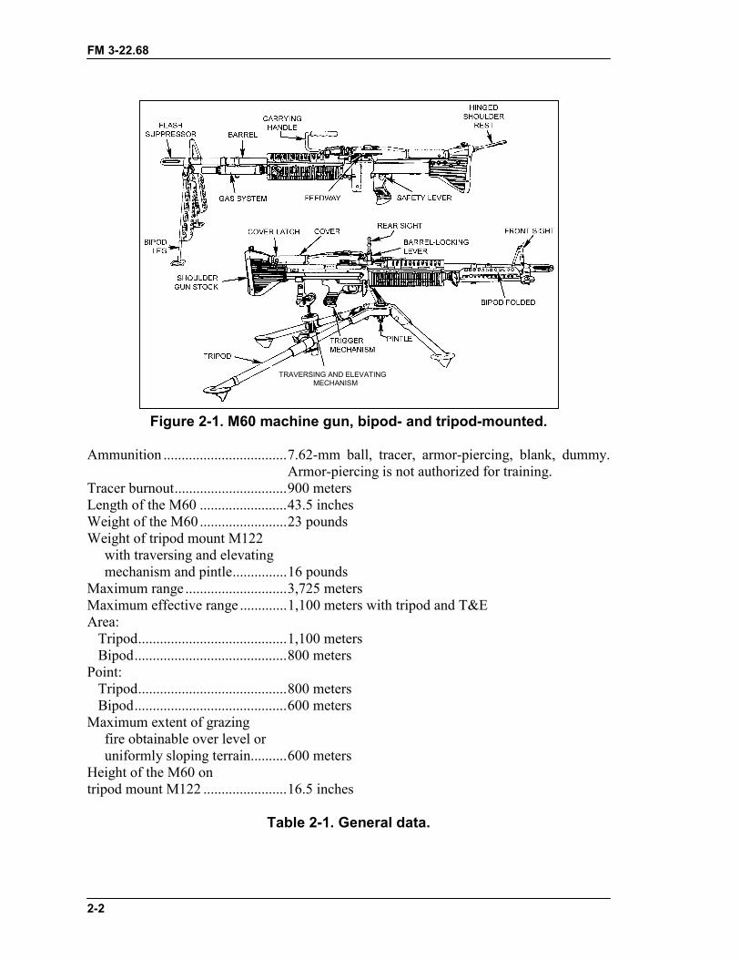
FM 3-22.68
2-2
Figure 2-1. M60 machine gun, bipod- and tripod-mounted.
Ammunition ..................................7.62-mm ball, tracer, armor-piercing, blank, dummy.Armor-piercing is not authorized for training.
Tracer burnout...............................900 metersLength of the M60 ........................43.5 inchesWeight of the M60 ........................23 poundsWeight of tripod mount M122
with traversing and elevatingmechanism and pintle...............16 pounds
Maximum range ............................3,725 metersMaximum effective range .............1,100 meters with tripod and T&EArea: Tripod.........................................1,100 meters Bipod..........................................800 metersPoint: Tripod.........................................800 meters Bipod..........................................600 metersMaximum extent of grazing
fire obtainable over level oruniformly sloping terrain..........600 meters
Height of the M60 ontripod mount M122 .......................16.5 inches
Table 2-1. General data.
TRAVERSING AND ELEVATINGMECHANISM
FM 3-22.68
2-3
Rates of fire:Sustained ..................................100 rounds per minute.
6- to 9-round bursts.4 to 5 seconds between bursts.Barrel changed every 10 minutes.
Rapid ........................................200 rounds per minute.10- to 13-round bursts.2 to 3 seconds between bursts.Barrel changed every 2 minutes.
Cyclic .......................................550 rounds per minute.Fire continuous burst.Barrel changed every minute.
Basic load of ammunitionfor a three-man crew ................600 to 900 rounds.
Elevation, tripod controlled ..........+200 milsElevation, tripod free ....................+445 milsDepression, tripod controlled........-200 milsDepression, tripod free..................-445 milsTraverse, controlled by
traversing and elevatingmechanism................................100 mils
Normal sector of fire(with tripod) .............................875 mils
Table 2-1. General data (continued).
2-2. COMPONENTSThe major components of the M60 and their purposes are shown in Table 2-2 andFigures 2-2 and 2-3. The sights and safety lever are discussed in paragraphs a and b andshown in Figures 2-4 and 2-5.
COMPONENTS PURPOSES
(1) Stock assembly Provides a shoulder support for aiming and firing theM60 machine gun. The stock assembly has a shoulderrest.
(2) Buffer assembly Absorbs recoil from the bolt and operating rod assemblyat the end of the recoil movement.
(3) Bolt assembly Feeds, chambers, fires, and extracts, using thepropellant gases and recoil spring for power. It housesthe firing pin.
(4) Operating rod assembly Transfers power from propelling gases to the bolt andslide assemblies.
Table 2-2. Components and purposes.

FM 3-22.68
2-4
COMPONENTS PURPOSES
(5) Cover, hanger, and feedassembly
Feeds linked-belt ammunition. Holds the cartridges inposition for stripping, feeding, and chambering.
(6) Barrel assembly Houses cartridges for firing, directs projectiles, supportsfixed front sight, and provides passageway for operatinggases. The bipod supports the M60 in the proneposition. The telescopic legs can be adjusted to threedifferent lengths.
(7) Trigger assembly Controls the firing of the weapon.
(8) Forearm assembly Provides thermal insulation to protect the gunner’shands from heat. Has a slotted top to allow air tocirculate around the barrel for cooling purposes.
(9) Receiver assembly Supports all assembly major components and housesthe action of the weapon.
(10) Rear sight assembly Adjustable for both windage and elevation allowing thegunner to make changes rapidly.
(11) Cocking handle assembly Pulls the moving parts rearward. Moves in a guide railfixed to the right side of the receiver.
(12) Tripod (M122) assembly Together with the tripod, T&E mechanism, and pintle,provides a stable mount and permits a higher degree ofaccuracy and control.
Table 2-2. Components and purposes (continued).
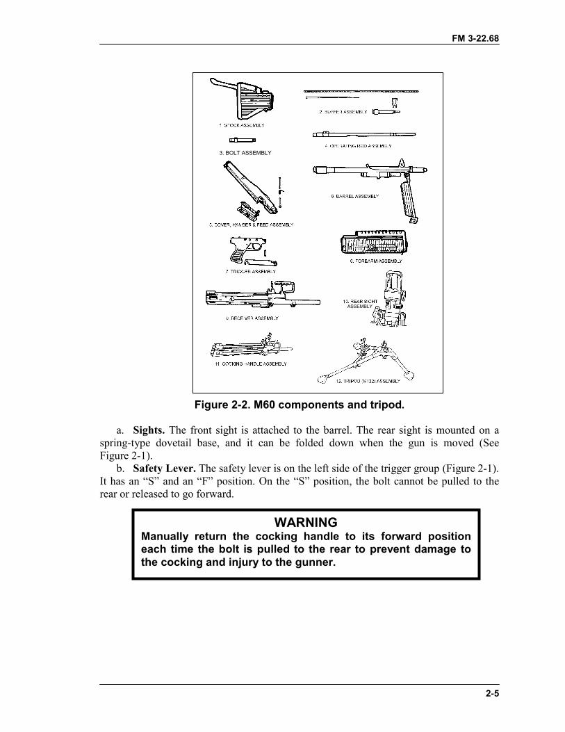
FM 3-22.68
2-5
Figure 2-2. M60 components and tripod.
a. Sights. The front sight is attached to the barrel. The rear sight is mounted on aspring-type dovetail base, and it can be folded down when the gun is moved (SeeFigure 2-1).
b. Safety Lever. The safety lever is on the left side of the trigger group (Figure 2-1).It has an “S” and an “F” position. On the “S” position, the bolt cannot be pulled to therear or released to go forward.
WARNINGManually return the cocking handle to its forward positioneach time the bolt is pulled to the rear to prevent damage tothe cocking and injury to the gunner.
3. BOLT ASSEMBLY
ASSEMBLY
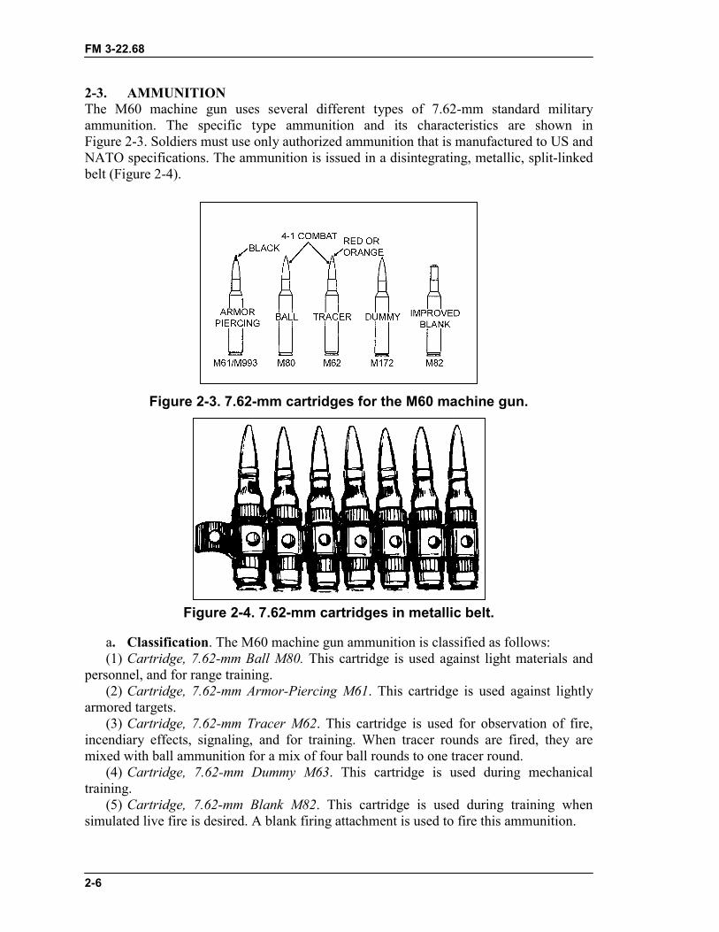
FM 3-22.68
2-6
2-3. AMMUNITIONThe M60 machine gun uses several different types of 7.62-mm standard militaryammunition. The specific type ammunition and its characteristics are shown inFigure 2-3. Soldiers must use only authorized ammunition that is manufactured to US andNATO specifications. The ammunition is issued in a disintegrating, metallic, split-linkedbelt (Figure 2-4).
Figure 2-3. 7.62-mm cartridges for the M60 machine gun.
Figure 2-4. 7.62-mm cartridges in metallic belt.
a. Classification. The M60 machine gun ammunition is classified as follows:(1) Cartridge, 7.62-mm Ball M80. This cartridge is used against light materials and
personnel, and for range training.(2) Cartridge, 7.62-mm Armor-Piercing M61. This cartridge is used against lightly
armored targets.(3) Cartridge, 7.62-mm Tracer M62. This cartridge is used for observation of fire,
incendiary effects, signaling, and for training. When tracer rounds are fired, they aremixed with ball ammunition for a mix of four ball rounds to one tracer round.
(4) Cartridge, 7.62-mm Dummy M63. This cartridge is used during mechanicaltraining.
(5) Cartridge, 7.62-mm Blank M82. This cartridge is used during training whensimulated live fire is desired. A blank firing attachment is used to fire this ammunition.
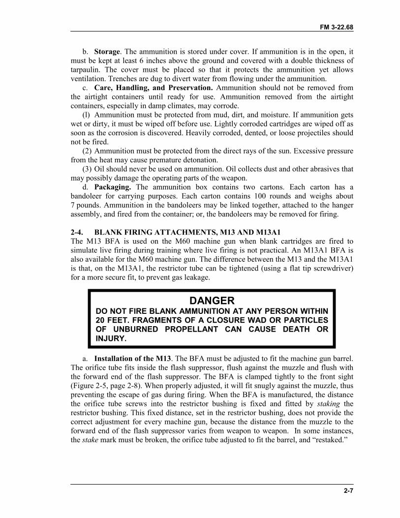
FM 3-22.68
2-7
b. Storage. The ammunition is stored under cover. If ammunition is in the open, itmust be kept at least 6 inches above the ground and covered with a double thickness oftarpaulin. The cover must be placed so that it protects the ammunition yet allowsventilation. Trenches are dug to divert water from flowing under the ammunition.
c. Care, Handling, and Preservation. Ammunition should not be removed fromthe airtight containers until ready for use. Ammunition removed from the airtightcontainers, especially in damp climates, may corrode.
(l) Ammunition must be protected from mud, dirt, and moisture. If ammunition getswet or dirty, it must be wiped off before use. Lightly corroded cartridges are wiped off assoon as the corrosion is discovered. Heavily corroded, dented, or loose projectiles shouldnot be fired.
(2) Ammunition must be protected from the direct rays of the sun. Excessive pressurefrom the heat may cause premature detonation.
(3) Oil should never be used on ammunition. Oil collects dust and other abrasives thatmay possibly damage the operating parts of the weapon.
d. Packaging. The ammunition box contains two cartons. Each carton has abandoleer for carrying purposes. Each carton contains 100 rounds and weighs about7 pounds. Ammunition in the bandoleers may be linked together, attached to the hangerassembly, and fired from the container; or, the bandoleers may be removed for firing.
2-4. BLANK FIRING ATTACHMENTS, M13 AND M13A1The M13 BFA is used on the M60 machine gun when blank cartridges are fired tosimulate live firing during training where live firing is not practical. An M13A1 BFA isalso available for the M60 machine gun. The difference between the M13 and the M13A1is that, on the M13A1, the restrictor tube can be tightened (using a flat tip screwdriver)for a more secure fit, to prevent gas leakage.
a. Installation of the M13. The BFA must be adjusted to fit the machine gun barrel.The orifice tube fits inside the flash suppressor, flush against the muzzle and flush withthe forward end of the flash suppressor. The BFA is clamped tightly to the front sight(Figure 2-5, page 2-8). When properly adjusted, it will fit snugly against the muzzle, thuspreventing the escape of gas during firing. When the BFA is manufactured, the distancethe orifice tube screws into the restrictor bushing is fixed and fitted by staking therestrictor bushing. This fixed distance, set in the restrictor bushing, does not provide thecorrect adjustment for every machine gun, because the distance from the muzzle to theforward end of the flash suppressor varies from weapon to weapon. In some instances,the stake mark must be broken, the orifice tube adjusted to fit the barrel, and “restaked.”
DANGERDO NOT FIRE BLANK AMMUNITION AT ANY PERSON WITHIN20 FEET. FRAGMENTS OF A CLOSURE WAD OR PARTICLESOF UNBURNED PROPELLANT CAN CAUSE DEATH ORINJURY.
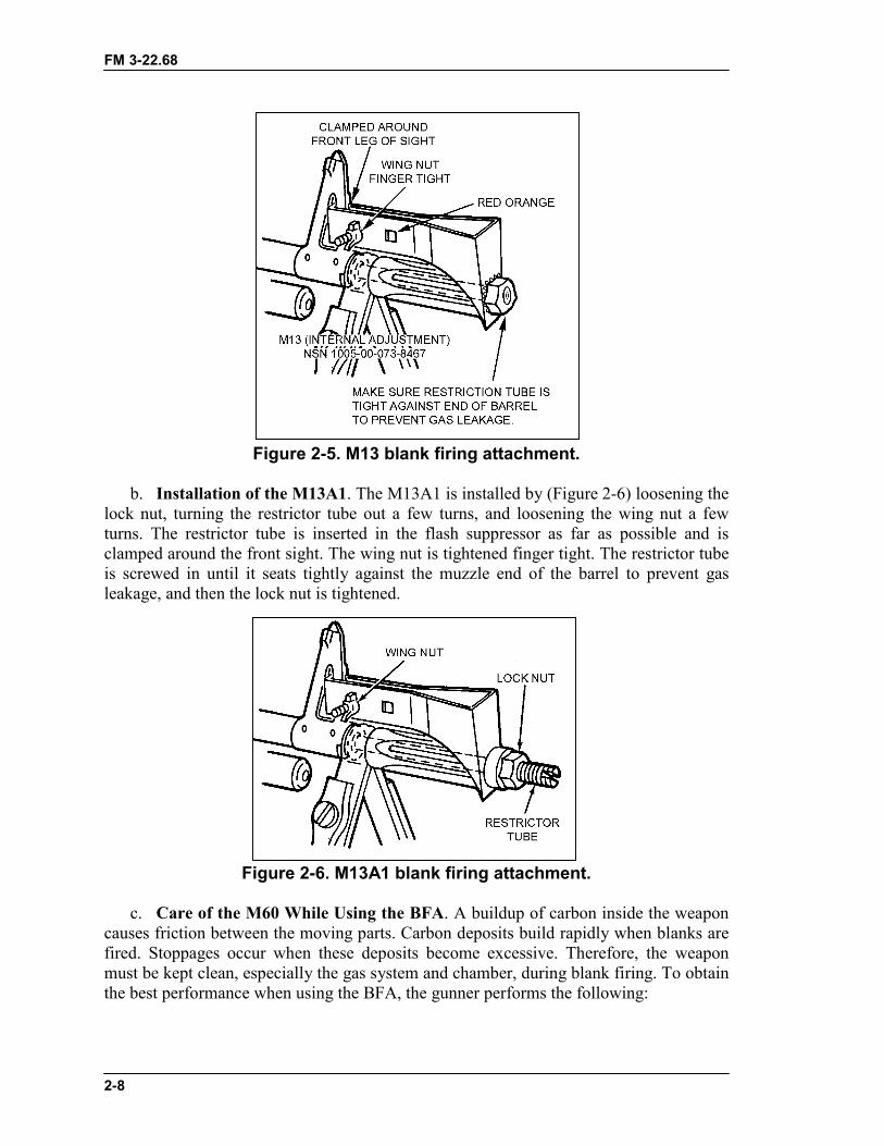
FM 3-22.68
2-8
Figure 2-5. M13 blank firing attachment.
b. Installation of the M13A1. The M13A1 is installed by (Figure 2-6) loosening thelock nut, turning the restrictor tube out a few turns, and loosening the wing nut a fewturns. The restrictor tube is inserted in the flash suppressor as far as possible and isclamped around the front sight. The wing nut is tightened finger tight. The restrictor tubeis screwed in until it seats tightly against the muzzle end of the barrel to prevent gasleakage, and then the lock nut is tightened.
Figure 2-6. M13A1 blank firing attachment.
c. Care of the M60 While Using the BFA. A buildup of carbon inside the weaponcauses friction between the moving parts. Carbon deposits build rapidly when blanks arefired. Stoppages occur when these deposits become excessive. Therefore, the weaponmust be kept clean, especially the gas system and chamber, during blank firing. To obtainthe best performance when using the BFA, the gunner performs the following:
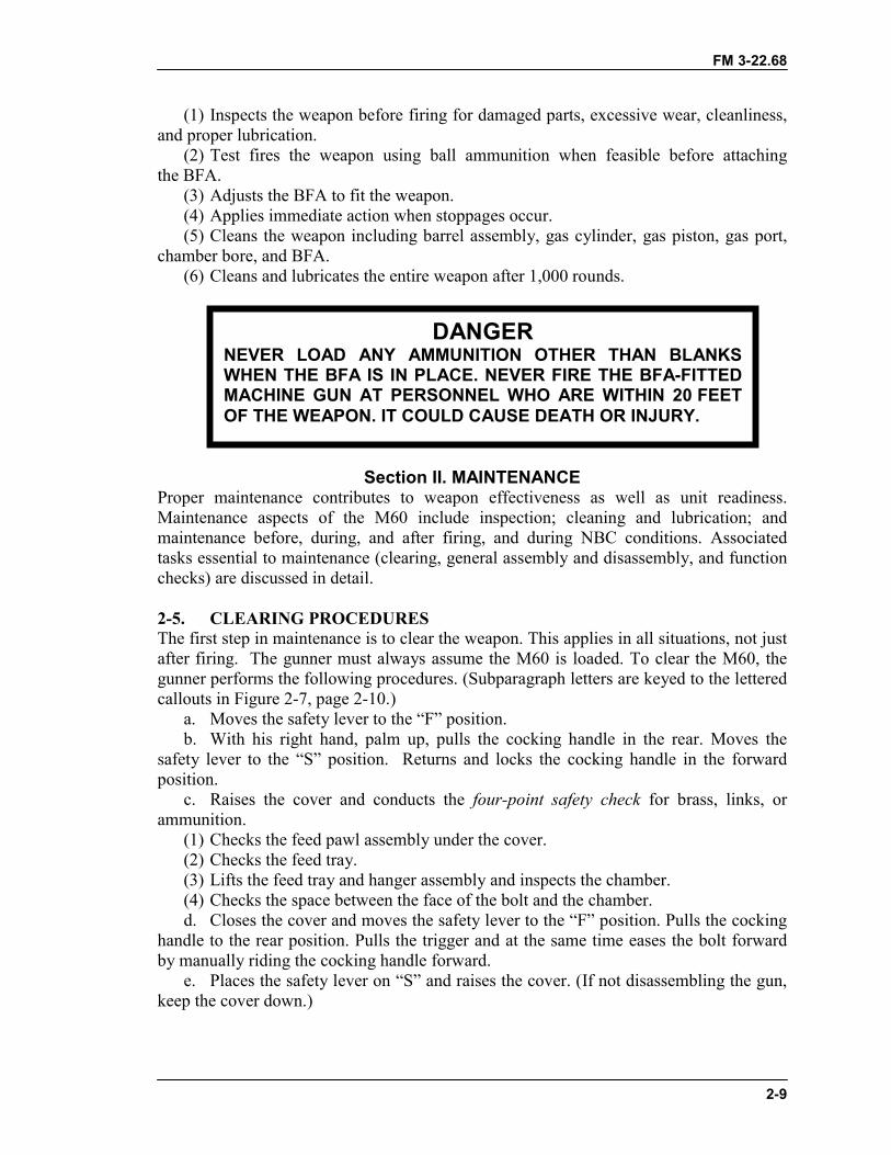
FM 3-22.68
2-9
(1) Inspects the weapon before firing for damaged parts, excessive wear, cleanliness,and proper lubrication.
(2) Test fires the weapon using ball ammunition when feasible before attachingthe BFA.
(3) Adjusts the BFA to fit the weapon.(4) Applies immediate action when stoppages occur.(5) Cleans the weapon including barrel assembly, gas cylinder, gas piston, gas port,
chamber bore, and BFA.(6) Cleans and lubricates the entire weapon after 1,000 rounds.
Section II. MAINTENANCEProper maintenance contributes to weapon effectiveness as well as unit readiness.Maintenance aspects of the M60 include inspection; cleaning and lubrication; andmaintenance before, during, and after firing, and during NBC conditions. Associatedtasks essential to maintenance (clearing, general assembly and disassembly, and functionchecks) are discussed in detail.
2-5. CLEARING PROCEDURESThe first step in maintenance is to clear the weapon. This applies in all situations, not justafter firing. The gunner must always assume the M60 is loaded. To clear the M60, thegunner performs the following procedures. (Subparagraph letters are keyed to the letteredcallouts in Figure 2-7, page 2-10.)
a. Moves the safety lever to the “F” position.b. With his right hand, palm up, pulls the cocking handle in the rear. Moves the
safety lever to the “S” position. Returns and locks the cocking handle in the forwardposition.
c. Raises the cover and conducts the four-point safety check for brass, links, orammunition.
(1) Checks the feed pawl assembly under the cover.(2) Checks the feed tray.(3) Lifts the feed tray and hanger assembly and inspects the chamber.(4) Checks the space between the face of the bolt and the chamber.d. Closes the cover and moves the safety lever to the “F” position. Pulls the cocking
handle to the rear position. Pulls the trigger and at the same time eases the bolt forwardby manually riding the cocking handle forward.
e. Places the safety lever on “S” and raises the cover. (If not disassembling the gun,keep the cover down.)
DANGERNEVER LOAD ANY AMMUNITION OTHER THAN BLANKSWHEN THE BFA IS IN PLACE. NEVER FIRE THE BFA-FITTEDMACHINE GUN AT PERSONNEL WHO ARE WITHIN 20 FEETOF THE WEAPON. IT COULD CAUSE DEATH OR INJURY.
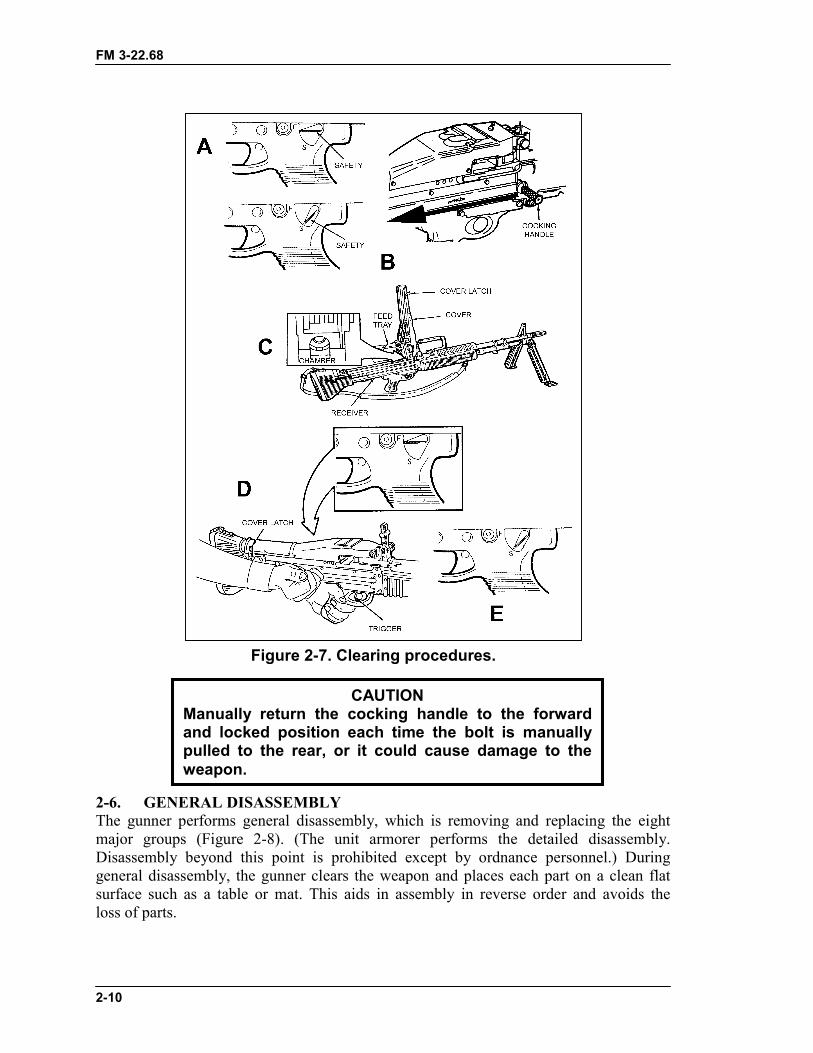
FM 3-22.68
2-10
Figure 2-7. Clearing procedures.
2-6. GENERAL DISASSEMBLYThe gunner performs general disassembly, which is removing and replacing the eightmajor groups (Figure 2-8). (The unit armorer performs the detailed disassembly.Disassembly beyond this point is prohibited except by ordnance personnel.) Duringgeneral disassembly, the gunner clears the weapon and places each part on a clean flatsurface such as a table or mat. This aids in assembly in reverse order and avoids theloss of parts.
CAUTIONManually return the cocking handle to the forwardand locked position each time the bolt is manuallypulled to the rear, or it could cause damage to theweapon.
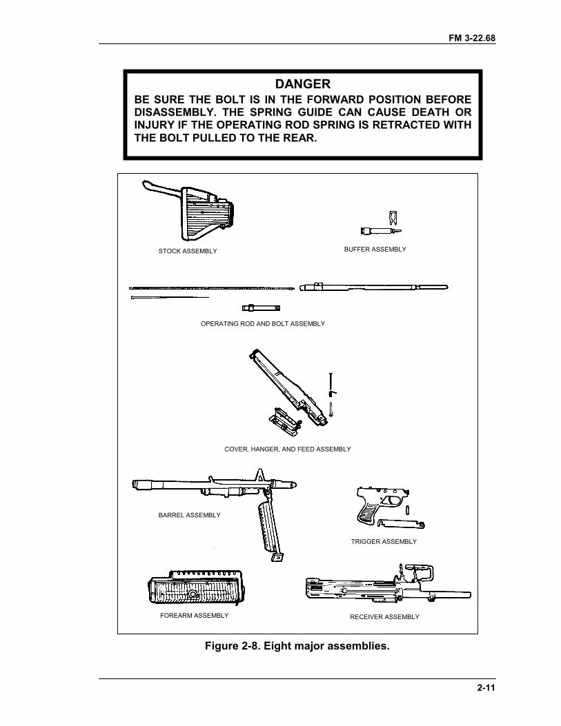
FM 3-22.68
2-11
Figure 2-8. Eight major assemblies.
DANGERBE SURE THE BOLT IS IN THE FORWARD POSITION BEFOREDISASSEMBLY. THE SPRING GUIDE CAN CAUSE DEATH ORINJURY IF THE OPERATING ROD SPRING IS RETRACTED WITHTHE BOLT PULLED TO THE REAR.
STOCK ASSEMBLY BUFFER ASSEMBLY
OPERATING ROD AND BOLT ASSEMBLY
COVER, HANGER, AND FEED ASSEMBLY
BARREL ASSEMBLY
TRIGGER ASSEMBLY
FOREARM ASSEMBLY RECEIVER ASSEMBLY
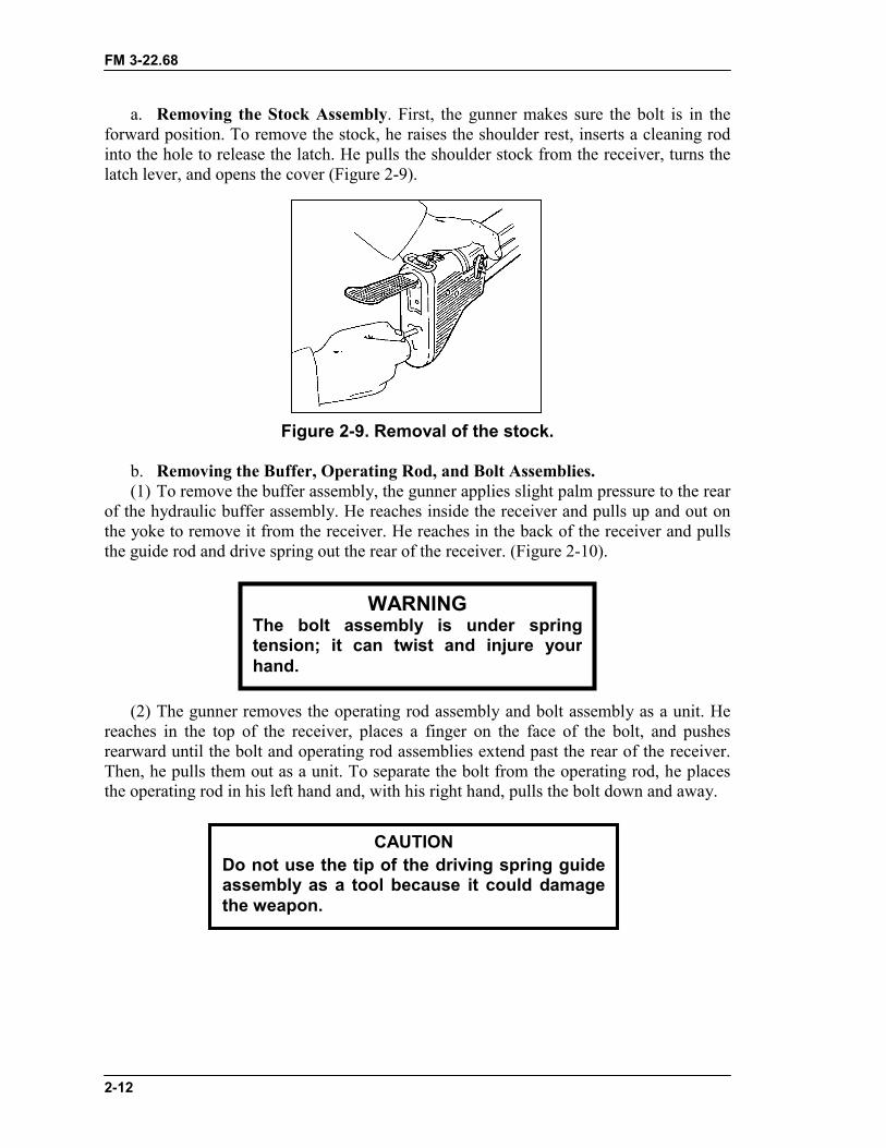
FM 3-22.68
2-12
a. Removing the Stock Assembly. First, the gunner makes sure the bolt is in theforward position. To remove the stock, he raises the shoulder rest, inserts a cleaning rodinto the hole to release the latch. He pulls the shoulder stock from the receiver, turns thelatch lever, and opens the cover (Figure 2-9).
Figure 2-9. Removal of the stock.
b. Removing the Buffer, Operating Rod, and Bolt Assemblies.(1) To remove the buffer assembly, the gunner applies slight palm pressure to the rear
of the hydraulic buffer assembly. He reaches inside the receiver and pulls up and out onthe yoke to remove it from the receiver. He reaches in the back of the receiver and pullsthe guide rod and drive spring out the rear of the receiver. (Figure 2-10).
(2) The gunner removes the operating rod assembly and bolt assembly as a unit. Hereaches in the top of the receiver, places a finger on the face of the bolt, and pushesrearward until the bolt and operating rod assemblies extend past the rear of the receiver.Then, he pulls them out as a unit. To separate the bolt from the operating rod, he placesthe operating rod in his left hand and, with his right hand, pulls the bolt down and away.
CAUTIONDo not use the tip of the driving spring guideassembly as a tool because it could damagethe weapon.
WARNINGThe bolt assembly is under springtension; it can twist and injure yourhand.
FM 3-22.68
2-13
Figure 2-10. Removal of the buffer, operating rod, and bolt assemblies.
FM 3-22.68
2-14
c. Removing the Cover, Hanger and Cartridge Feed Tray Assemblies. Thegunner uses a cleaning rod to unlatch the hook of the hinge pin latch. He removes thehinge pin latch and cover hinge pin. He removes the cover assembly, torsion spring, andhanger and cartridge feed tray assembly (Figure 2-11).
Figure 2-11. Removal of the cover, hanger and cartridgefeed tray assemblies.
HANGER AND CARTRIDGEFEED TRAY ASSEMBLY
FM 3-22.68
2-15
d. Removing the Barrel Assembly. The gunner pushes in the spring detent, raisesthe barrel lock, and removes the barrel assembly (Figure 2-12).
Figure 2-12. Removal of the barrel assembly.
e. Removing the Trigger Mechanism Grip Assembly. The gunner pushes in andremoves the flat leaf spring. He pushes out the front pin and slides the trigger mechanismgrip assembly slightly forward, then pulls it out to remove it (Figure 2-13).
Figure 2-13. Removal of the trigger mechanism grip assembly.
f. Removing the Forearm Assembly. The gunner inserts a cleaning rod or thereamer portion of a combination wrench through the round opening in the forearmassembly, and then he pushes down on the spring. He lifts and gently slides the forearmassembly from the receiver (Figure 2-14, page 2-16).
CAUTIONBe careful not to damage the internal ribs of theforearm assembly. It can cause damage to theweapon.
BARREL AND BIPODASSEMBLY
FM 3-22.68
2-16
Figure 2-14. Removal of the forearm assembly.
g. Removing the Receiver Assembly. Once the forearm assembly is removed, thepart remaining is the receiver assembly, and general disassembly is complete.
2-7. INSPECTIONInspection begins with the weapon disassembled in its major groups. Shiny surfaces donot mean the parts are unserviceable. The gunner inspects each area of the weapon andrelated equipment for the conditions indicated. Any broken or missing parts should berepaired or replaced IAW TM 9-1005-224-10. The gunner should perform Preventivemaintenance checks and services (PMCS) every 90 days. If the weapon has not been usedin 90 days, the PMCS in the operator’s manual should be performed regardless. If he seesrust on a weapon, he should perform PMCS immediately.
a. Stock Assembly. The stock assembly should not be cracked and must fit securelyon the receiver assembly. The shoulder rest and latch lever should function correctly.
b. Buffer Assembly. The buffer yoke and recess should not be burred, cracked, orbent. The buffer plunger must fit easily into the recess in the spring guide.
c. Operating Rod Assembly. The operating rod, yoke, sear notch, and pins shouldnot have burrs, cracks, or chips. The roller should operate freely. The driving springshould have tension and should not have kinks, breaks, or wear. The guide assembly stopshould be tight. If it is loose, the gunner notifies unit maintenance.
d. Bolt Assembly. The bolt assembly is checked for burrs or cracks, especially inthe locking lug area.
(1) The roller should operate freely and not be cracked.(2) The spring should not be kinked.(3) The threads on the bolt plug assembly and in the breech bolt should not be
damaged.e. Cover Assembly. The cover assembly is checked for burrs, cracks, looseness, or
missing parts. The spring action of the front and rear cartridge guides, feed pawls(beneath the cartridge guides), and feed cam assembly are checked. The feed camassembly should be secure and operate freely.
f. Hanger and Cartridge Feed Tray Assembly. The hanger and cartridge feed trayassembly is checked for burrs, cracks, and missing or loose parts. The feed tray is
FM 3-22.68
2-17
checked to make sure it fits on the receiver and that the cartridge-retaining pawl worksproperly. The hanger is checked for obstructions.
g. Barrel Assembly. The barrel assembly is checked for burrs, cracks, and wear,especially in the barrel socket area. The sight and flash suppressor are checked to makesure they are tight. The bipod should work properly, the legs should be straight, andconnections should be tight. The bipod plungers should operate smoothly.
h. Trigger Mechanism Grip Assembly. The sear is checked for chips, cracks, orsigns of wear. The sear plunger and spring are checked for wear.
i. Forearm Assembly. The forearm assembly is checked for damage.j. Receiver Assembly. The receiver rails are checked for burrs and wear. The
cocking handle should move freely.k. M122 Mount. The T&E mechanism should not bind. The numbers on the scales
and dials must be legible.(1) Distinct clicks must be heard when the handwheels are turned. Index lines should
be calibrated with the indicator pointer.(2) The pintle should fit snugly in the pintle bushing, and the pintle lock should hold
the pintle securely.(3) The sleeve latch should function properly, and the traversing bar should be tight
when the tripod legs are extended and latched.l. Carrying Case. Maintenance tools and equipment should be complete and
serviceable. The case should be serviceable. Frequent washing of the case should beavoided. Such washing may destroy the waterproofing and shrink the case.
2-8. CLEANING, LUBRICATION, AND PREVENTIVE MAINTENANCEThe M60 machine gun should be cleaned immediately after firing. The gunnerdisassembles the M60 into its major groups for cleaning. All metal components andsurfaces that have been exposed to powder fouling should be cleaned using CLP on abore-cleaning patch. The CLP is used on the bristles of the receiver brush to clean thereceiver. After the M60 is cleaned and wiped dry, a thin coat of CLP is rubbed on with acloth. This lubricates and preserves the exposed metal parts during all normaltemperature ranges.
a. The gas cylinder components are removed and cleaned only wheninspection shows that the piston will not move within the cylinder when the barrelis tilted end-for-end. Unit maintenance personnel must supervise disassembly ofthe gas system. The receiver brush and swab-holding section of the cleaning rodmay be used to clean the interior of the gas cylinder. When CLP is used, the gascylinder and gas piston must be wiped dry before assembly. After assembly, thepiston is checked for free movement. The unit armorer replaces safety wire. Thegunner cleans the rest of the weapon as follows:
CAUTIONDo not get CLP in the gas cylinder when cleaning thebarrel. Turn the barrel upside down so that the gascylinder is above the barrel during cleaning.
FM 3-22.68
2-18
(1) Cleans the bore using CLP and a bore brush attached to a cleaning rod.Does not reverse the direction of the bore brush while in the bore.
(a) Runs the brush through the bore several times until most of the powderfouling and other foreign matter have been removed.
(b) Swabs the bore several times using a cleaning rod and a swab wetwith CLP.
(c) Swabs the bore several times using a cleaning rod and dry swab.(2) Cleans the chamber using CLP and a chamber brush attached to a
cleaning rod.(a) Runs the brush through the chamber several times until most of the
powder fouling and other foreign matter have been removed.(b) Swabs the chamber several times using a cleaning rod and a swab wet
with CLP.(c) Swabs the chamber several times using a cleaning rod and dry swab.(3) Cleans the receiver using a receiver brush and CLP.(a) Brushes the receiver until most of the powder fouling and other foreign
matter have been removed.(b) Swabs the receiver several times using a cleaning rod section and a swab
wet with CLP.(c) Swabs the receiver several times using a cleaning rod section and
dry swab.(4) Wipes all the parts of the weapon except those that are rubber coated,
using a rag wet with CLP.(5) Dries completely all parts cleaned with CLP.(6) Lubricates the following moving parts with CLP as instructed:(a) Barrel Assembly. Lubricates on the camming surfaces of the bolt-
locking lugs.(b) Operating Rod Assembly. Lubricates on the rollers and those surfaces
immediately below the yoke that ride within the receiver rails.(c) Cover assembly. Lubricates inside the feed cam assembly.(d) Bolt assembly. Lubricates on the bolt locking lugs and cam actuator roller,
and in the camming recess (for the operating rod).b. After lubricating, the components are cycled by hand to spread the CLP.
Weapons fired infrequently or stored for prolonged periods should have a lightfilm of CLP applied to the interior of the gas cylinder and the gas pistonimmediately after cleaning or inspection. Preventive maintenance is performedevery 90 days, unless inspection reveals more frequent servicing is necessary. Theuse of the lubricant does not eliminate the requirement for cleaning and inspectingto ensure that corrosion has not formed. Before the weapon is used, the gassystem and components must be clean and free of oil and lubricants.
c. All exposed surfaces of the M122 tripod, pintle assembly, and T&Emechanism are wiped down with a clean rag. For stubborn areas with hard-to-remove dirt, a steel brush or bore brush is used to loosen the particles. Then aclean rag is used to wipe them down and CLP is used to lubricate them.
d. The following procedures apply to cleaning and lubricating the M60during unusual conditions:
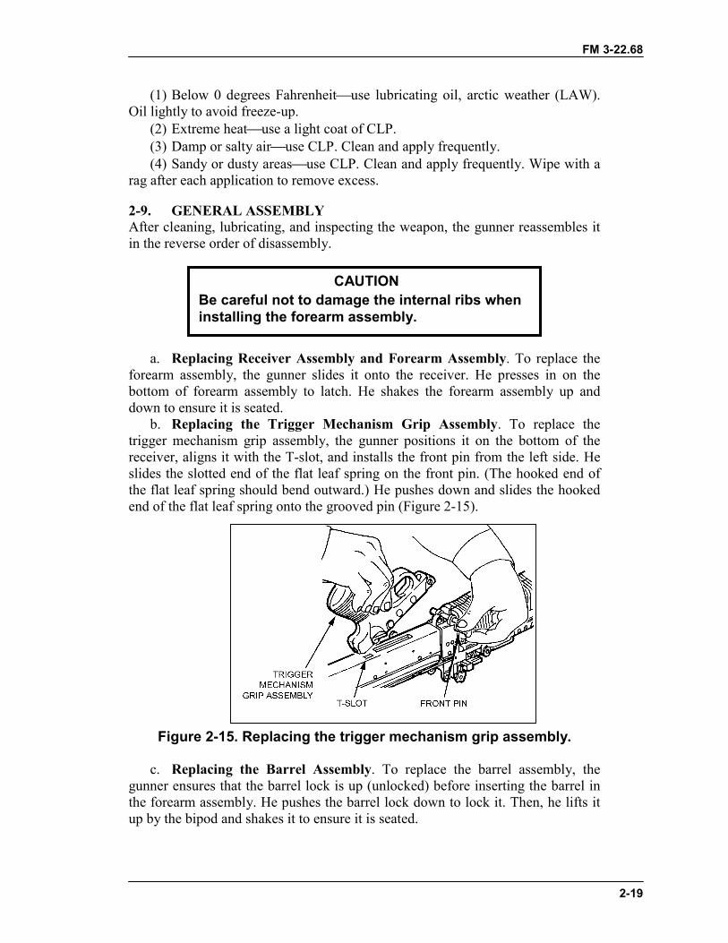
FM 3-22.68
2-19
(1) Below 0 degrees Fahrenheit�use lubricating oil, arctic weather (LAW).Oil lightly to avoid freeze-up.
(2) Extreme heat�use a light coat of CLP.(3) Damp or salty air�use CLP. Clean and apply frequently.(4) Sandy or dusty areas�use CLP. Clean and apply frequently. Wipe with a
rag after each application to remove excess.
2-9. GENERAL ASSEMBLYAfter cleaning, lubricating, and inspecting the weapon, the gunner reassembles itin the reverse order of disassembly.
a. Replacing Receiver Assembly and Forearm Assembly. To replace theforearm assembly, the gunner slides it onto the receiver. He presses in on thebottom of forearm assembly to latch. He shakes the forearm assembly up anddown to ensure it is seated.
b. Replacing the Trigger Mechanism Grip Assembly. To replace thetrigger mechanism grip assembly, the gunner positions it on the bottom of thereceiver, aligns it with the T-slot, and installs the front pin from the left side. Heslides the slotted end of the flat leaf spring on the front pin. (The hooked end ofthe flat leaf spring should bend outward.) He pushes down and slides the hookedend of the flat leaf spring onto the grooved pin (Figure 2-15).
Figure 2-15. Replacing the trigger mechanism grip assembly.
c. Replacing the Barrel Assembly. To replace the barrel assembly, thegunner ensures that the barrel lock is up (unlocked) before inserting the barrel inthe forearm assembly. He pushes the barrel lock down to lock it. Then, he lifts itup by the bipod and shakes it to ensure it is seated.
CAUTIONBe careful not to damage the internal ribs wheninstalling the forearm assembly.
FM 3-22.68
2-20
d. Replacing the Cover, Hanger and Cartridge Feed Tray Assembly. Thegunner positions the hanger and cartridge feed tray assembly on the receiver. Heinstalls the torsion spring and cover assembly and makes sure the ends of thetorsion spring stick in the holes of the cover and receiver. (The hinge pin isinserted from right to left.) The gunner applies slight pressure to line up thetorsion spring and inserts the cover hinge pin. He installs the hinge pin latchthrough the hinge pin until it locks. He keeps the cover assembly open until themachine gun is assembled.
e. Replacing the Bolt Assembly, Operating Rod Assembly, and BufferAssembly. The gunner places the yoke of the operating rod assembly against thespool of the firing pin in the slot of the bolt assembly (Figure 2-16). Then, hepushes the spool forward. He seats the yoke between the spools of the firing pinand lets the yoke slide back in the bolt assembly.
(1) Slides the operating rod assembly with the bolt assembly into the weapon.Turns the bolt assembly so that the stripping lugs line up with the upper rails.Pushes in until the stripping lugs engage the rails.
(2) Turns the roller straight up and pushes the bolt assembly and operating rodassembly as a unit into the weapon.
(3) Pulls and holds the trigger while pushing the bolt assembly into thereceiver until it locks in place. (4) Installs the drive spring and guide assembly in the rear of the receiver.
(5) Inserts the buffer assembly against the end of the guide assembly and pushes untilthe groove on the buffer assembly lines up with the slot for buffer retaining yoke. Insertsthe buffer retaining yoke.
f. Replacing the Stock. The gunner positions the stock on the rear of the receiverand pushes until it snaps in place. He pulls the cocking handle to the rear to lock the boltassembly to the rear, and then he places the safety on “S.” He closes the cover. Whileholding the charging handle, he pulls the trigger and eases the charging handle forward.
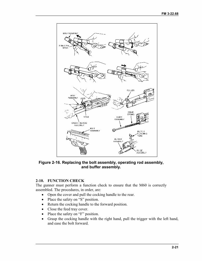
FM 3-22.68
2-21
Figure 2-16. Replacing the bolt assembly, operating rod assembly,and buffer assembly.
2-10. FUNCTION CHECKThe gunner must perform a function check to ensure that the M60 is correctlyassembled. The procedures, in order, are:
� Open the cover and pull the cocking handle to the rear.� Place the safety on “S” position.� Return the cocking handle to the forward position.� Close the feed tray cover.� Place the safety on “F” position.� Grasp the cocking handle with the right hand, pull the trigger with the left hand,
and ease the bolt forward.
FM 3-22.68
2-22
2-11. MAINTENANCE PROCEDURESMaintenance of the M60 requires certain actions to be taken before, during, andafter firing.
a. Before firing�� Wipe the bore dry.� Inspect the weapon as outlined in operator's TM.� Inspect the spare barrel.� Lubricate the weapon.
b. During firing�� Change the barrels. Barrel changing will prolong the life of both barrels.� Periodically inspect the weapon to ensure that it is properly lubricated.� When malfunctions or stoppages occur, follow the procedures in Section IV.
c. After firing�� Clear and clean the weapon immediately.� Every 90 days during inactivity, clean and lubricate the weapon unless
inspection reveals more frequent servicing is necessary (TM 9-1005-224-10).
2-12. MAINTENANCE DURING NUCLEAR, BIOLOGICAL, CHEMICALCONDITIONSIf the M60 machine gun is contaminated by chemical, biological, or radiological agents,the gunner takes the appropriate action to reduce the exposure and minimize thepenetration.
a. Chemical. The gunner uses towelettes from the M258A1 kit to wipe off theweapon. If these are not available, he washes the weapon with soap and water.
b. Biological. The gunner uses towelettes or soap and water as above.c. Radiological. The gunner wipes the weapon with warm soapy water if it is
available. If not, he uses towelettes or rags. (For more details, see FM 3-5.)
Section III. OPERATION AND FUNCTIONThis section discusses the operation of the M60 machine gun. This includes loading,firing, unloading, cycle of functioning, adjustment of the sight, using both the bipod andtripod, and use of the M60 on a vehicular mount.
2-13. OPERATIONThe M60 machine gun is loaded, fired, unloaded, and cleared from the open-boltposition. The safety lever must be in the “F” position before the bolt can be pulled to therear. Before use belted ammunition must be linked with the double link at the open end ofthe bandoleer. It must be free of dirt and corrosion.
2-14. LOADINGThe gunner makes sure the weapon is cleared as previously described. He places thesafety lever on “F”. With his palm up, he pulls the cocking handle to the rear, then pushesit forward until it locks. With the bolt held to the rear, he places the safety lever on “S”and manually returns the cocking handle to the forward position. He turns the latch leverand opens the cover. He raises the cartridge feed tray and places the bandoleer on thebandoleer hanger. He places the first round of the belt in the feed groove with the double
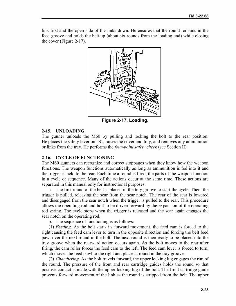
FM 3-22.68
2-23
link first and the open side of the links down. He ensures that the round remains in thefeed groove and holds the belt up (about six rounds from the loading end) while closingthe cover (Figure 2-17).
Figure 2-17. Loading.
2-15. UNLOADINGThe gunner unloads the M60 by pulling and locking the bolt to the rear position.He places the safety lever on “S”, raises the cover and tray, and removes any ammunitionor links from the tray. He performs the four-point safety check (see Section II).
2-16. CYCLE OF FUNCTIONINGThe M60 gunners can recognize and correct stoppages when they know how the weaponfunctions. The weapon functions automatically as long as ammunition is fed into it andthe trigger is held to the rear. Each time a round is fired, the parts of the weapon functionin a cycle or sequence. Many of the actions occur at the same time. These actions areseparated in this manual only for instructional purposes.
a. The first round of the belt is placed in the tray groove to start the cycle. Then, thetrigger is pulled, releasing the sear from the sear notch. The rear of the sear is loweredand disengaged from the sear notch when the trigger is pulled to the rear. This procedureallows the operating rod and bolt to be driven forward by the expansion of the operatingrod spring. The cycle stops when the trigger is released and the sear again engages thesear notch on the operating rod.
b. The sequence of functioning is as follows:(1) Feeding. As the bolt starts its forward movement, the feed cam is forced to the
right causing the feed cam lever to turn in the opposite direction and forcing the belt feedpawl over the next round in the bolt. The next round is then ready to be placed into thetray groove when the rearward action occurs again. As the bolt moves to the rear afterfiring, the cam roller forces the feed cam to the left. The feed cam lever is forced to turn,which moves the feed pawl to the right and places a round in the tray groove.
(2) Chambering. As the bolt travels forward, the upper locking lug engages the rim ofthe round. The pressure of the front and rear cartridge guides holds the round so thatpositive contact is made with the upper locking lug of the bolt. The front cartridge guideprevents forward movement of the link as the round is stripped from the belt. The upper
FM 3-22.68
2-24
locking lug carries the round forward. The chambering ramp causes the nose of the roundto be cammed downward into the chamber. When the round is fully seated in thechamber, the extractor snaps over the rim of the round, and the ejector on the rail insidethe receiver is depressed.
(3) Locking. As the round is chambered, the bolt enters the barrel socket. The upperand lower locking lugs contact the bolt camming surfaces inside the barrel and startturning the bolt clockwise. The action of the operating rod yoke against the bolt cammingslot as the operating rod continues forward turns the bolt, completing its 90-degree(one-quarter turn) clockwise rotation. Locking is now complete.
(4) Firing. After the bolt is fully forward and locked, the operating rod continues togo forward, independent of the bolt, for a short distance. The yoke, engaged between thefiring pin spools, carries the firing pin through the face of the bolt. The firing pin strikesthe primer of the round and the primer fires the round.
(5) Unlocking. After the round is fired and the bullet passes the gas port, part of theexpanding gases go into the gas regulator through the gas plug. The rapidly expandinggases enter the hollow gas piston, forcing the piston to the rear. As the operating rodcontinues to the rear, the operating rod yoke acts against the bolt camming slot. Thiscauses the bolt to begin its counterclockwise rotation. The upper and lower locking lugsof the bolt contact the bolt camming surfaces inside the barrel socket and, as the boltcontinues toward the rear, it completes a one-quarter turn counterclockwise. The rotationand movement to the rear unlocks the bolt from the barrel socket. Unlocking begins asthe yoke of the operating rod contacts the curve of the bolt camming slot and ends as thebolt clears the end of the barrel socket.
(6) Extracting. Extracting begins during the unlocking cycle. The rotation of the boltloosens the cartridge case in the chamber. As the piston and bolt move to the rear, theextractor pulls the cartridge case from the chamber.
(7) Ejecting. As the cartridge case is pulled from the chamber, the bolt passes by theejector. This procedure causes the ejector clip to expand, forcing the ejector to push theexpended cartridge. The extractor grips the right side of the cartridge and causes it to spinfrom the weapon as it reaches the ejection port. The empty belt links are forced out thelink ejection port as the rearward movement of the bolt causes the next round to bepositioned in the tray groove.
(8) Cocking. As the expanding gases force the gas piston to the rear, the operating rodfirst moves independently of the bolt. The yoke of the operating rod acts against the rearfiring pin spool, pulling the firing pin from the primer of the spent cartridge case.The action of the piston assembly, continuing to the rear with the firing pin, releases thecompression of the firing pin spring. As long as the trigger is held to the rear, the M60continues to complete the eight steps of functioning automatically. When the trigger isreleased and the sear engages the sear notch, the cycle of functioning is stopped and theweapon is cocked. To prevent undue wear to the sear and sear notch, the gunner musthold the trigger firmly to the rear during firing.
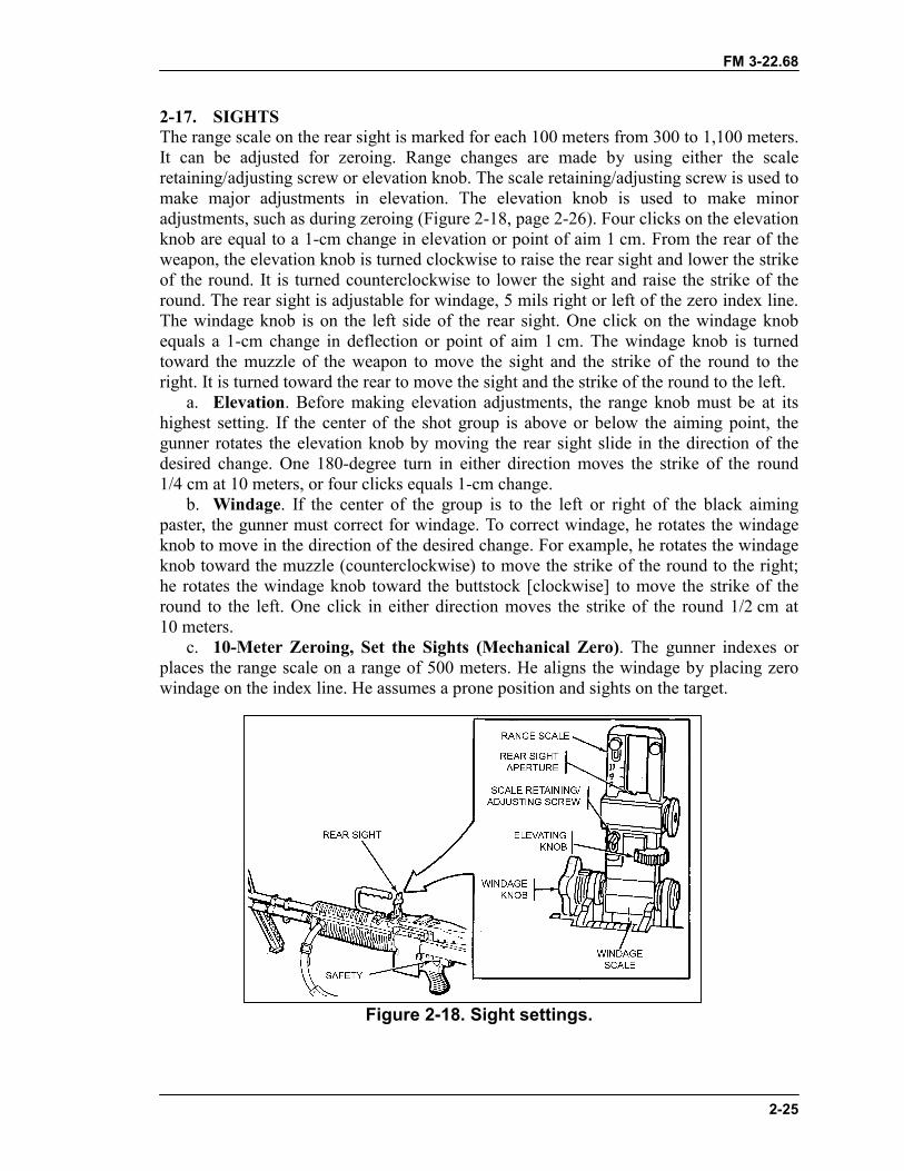
FM 3-22.68
2-25
2-17. SIGHTSThe range scale on the rear sight is marked for each 100 meters from 300 to 1,100 meters.It can be adjusted for zeroing. Range changes are made by using either the scaleretaining/adjusting screw or elevation knob. The scale retaining/adjusting screw is used tomake major adjustments in elevation. The elevation knob is used to make minoradjustments, such as during zeroing (Figure 2-18, page 2-26). Four clicks on the elevationknob are equal to a 1-cm change in elevation or point of aim 1 cm. From the rear of theweapon, the elevation knob is turned clockwise to raise the rear sight and lower the strikeof the round. It is turned counterclockwise to lower the sight and raise the strike of theround. The rear sight is adjustable for windage, 5 mils right or left of the zero index line.The windage knob is on the left side of the rear sight. One click on the windage knobequals a 1-cm change in deflection or point of aim 1 cm. The windage knob is turnedtoward the muzzle of the weapon to move the sight and the strike of the round to theright. It is turned toward the rear to move the sight and the strike of the round to the left.
a. Elevation. Before making elevation adjustments, the range knob must be at itshighest setting. If the center of the shot group is above or below the aiming point, thegunner rotates the elevation knob by moving the rear sight slide in the direction of thedesired change. One 180-degree turn in either direction moves the strike of the round1/4 cm at 10 meters, or four clicks equals 1-cm change.
b. Windage. If the center of the group is to the left or right of the black aimingpaster, the gunner must correct for windage. To correct windage, he rotates the windageknob to move in the direction of the desired change. For example, he rotates the windageknob toward the muzzle (counterclockwise) to move the strike of the round to the right;he rotates the windage knob toward the buttstock [clockwise] to move the strike of theround to the left. One click in either direction moves the strike of the round 1/2 cm at10 meters.
c. 10-Meter Zeroing, Set the Sights (Mechanical Zero). The gunner indexes orplaces the range scale on a range of 500 meters. He aligns the windage by placing zerowindage on the index line. He assumes a prone position and sights on the target.
Figure 2-18. Sight settings.
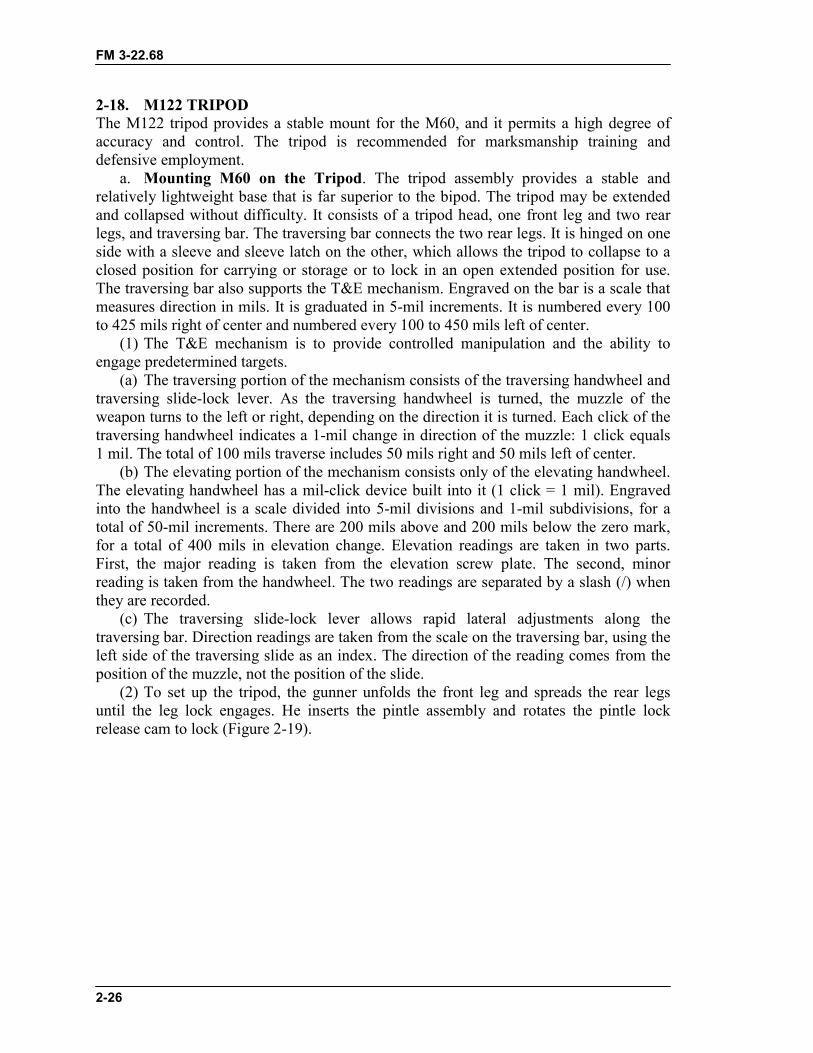
FM 3-22.68
2-26
2-18. M122 TRIPODThe M122 tripod provides a stable mount for the M60, and it permits a high degree ofaccuracy and control. The tripod is recommended for marksmanship training anddefensive employment.
a. Mounting M60 on the Tripod. The tripod assembly provides a stable andrelatively lightweight base that is far superior to the bipod. The tripod may be extendedand collapsed without difficulty. It consists of a tripod head, one front leg and two rearlegs, and traversing bar. The traversing bar connects the two rear legs. It is hinged on oneside with a sleeve and sleeve latch on the other, which allows the tripod to collapse to aclosed position for carrying or storage or to lock in an open extended position for use.The traversing bar also supports the T&E mechanism. Engraved on the bar is a scale thatmeasures direction in mils. It is graduated in 5-mil increments. It is numbered every 100to 425 mils right of center and numbered every 100 to 450 mils left of center.
(1) The T&E mechanism is to provide controlled manipulation and the ability toengage predetermined targets.
(a) The traversing portion of the mechanism consists of the traversing handwheel andtraversing slide-lock lever. As the traversing handwheel is turned, the muzzle of theweapon turns to the left or right, depending on the direction it is turned. Each click of thetraversing handwheel indicates a 1-mil change in direction of the muzzle: 1 click equals1 mil. The total of 100 mils traverse includes 50 mils right and 50 mils left of center.
(b) The elevating portion of the mechanism consists only of the elevating handwheel.The elevating handwheel has a mil-click device built into it (1 click = 1 mil). Engravedinto the handwheel is a scale divided into 5-mil divisions and 1-mil subdivisions, for atotal of 50-mil increments. There are 200 mils above and 200 mils below the zero mark,for a total of 400 mils in elevation change. Elevation readings are taken in two parts.First, the major reading is taken from the elevation screw plate. The second, minorreading is taken from the handwheel. The two readings are separated by a slash (/) whenthey are recorded.
(c) The traversing slide-lock lever allows rapid lateral adjustments along thetraversing bar. Direction readings are taken from the scale on the traversing bar, using theleft side of the traversing slide as an index. The direction of the reading comes from theposition of the muzzle, not the position of the slide.
(2) To set up the tripod, the gunner unfolds the front leg and spreads the rear legsuntil the leg lock engages. He inserts the pintle assembly and rotates the pintle lockrelease cam to lock (Figure 2-19).
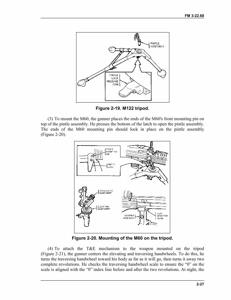
FM 3-22.68
2-27
Figure 2-19. M122 tripod.
(3) To mount the M60, the gunner places the ends of the M60's front mounting pin ontop of the pintle assembly. He presses the bottom of the latch to open the pintle assembly.The ends of the M60 mounting pin should lock in place on the pintle assembly(Figure 2-20).
Figure 2-20. Mounting of the M60 on the tripod.
(4) To attach the T&E mechanism to the weapon mounted on the tripod(Figure 2-21), the gunner centers the elevating and traversing handwheels. To do this, heturns the traversing handwheel toward his body as far as it will go, then turns it away twocomplete revolutions. He checks the traversing handwheel scale to ensure the “0” on thescale is aligned with the “0” index line before and after the two revolutions. At night, the
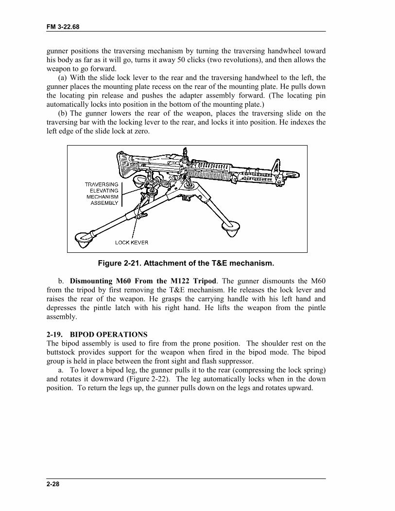
FM 3-22.68
2-28
gunner positions the traversing mechanism by turning the traversing handwheel towardhis body as far as it will go, turns it away 50 clicks (two revolutions), and then allows theweapon to go forward.
(a) With the slide lock lever to the rear and the traversing handwheel to the left, thegunner places the mounting plate recess on the rear of the mounting plate. He pulls downthe locating pin release and pushes the adapter assembly forward. (The locating pinautomatically locks into position in the bottom of the mounting plate.)
(b) The gunner lowers the rear of the weapon, places the traversing slide on thetraversing bar with the locking lever to the rear, and locks it into position. He indexes theleft edge of the slide lock at zero.
Figure 2-21. Attachment of the T&E mechanism.
b. Dismounting M60 From the M122 Tripod. The gunner dismounts the M60from the tripod by first removing the T&E mechanism. He releases the lock lever andraises the rear of the weapon. He grasps the carrying handle with his left hand anddepresses the pintle latch with his right hand. He lifts the weapon from the pintleassembly.
2-19. BIPOD OPERATIONSThe bipod assembly is used to fire from the prone position. The shoulder rest on thebuttstock provides support for the weapon when fired in the bipod mode. The bipodgroup is held in place between the front sight and flash suppressor.
a. To lower a bipod leg, the gunner pulls it to the rear (compressing the lock spring)and rotates it downward (Figure 2-22). The leg automatically locks when in the downposition. To return the legs up, the gunner pulls down on the legs and rotates upward.
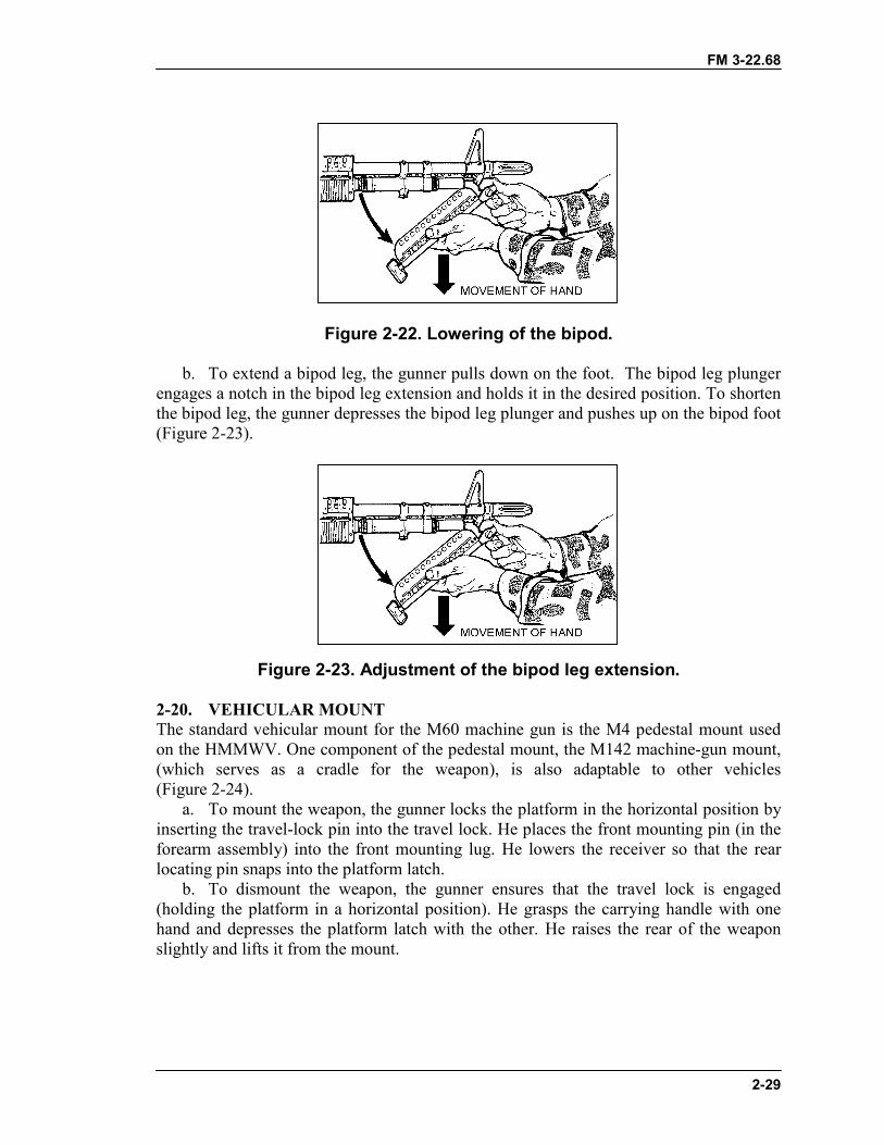
FM 3-22.68
2-29
Figure 2-22. Lowering of the bipod.
b. To extend a bipod leg, the gunner pulls down on the foot. The bipod leg plungerengages a notch in the bipod leg extension and holds it in the desired position. To shortenthe bipod leg, the gunner depresses the bipod leg plunger and pushes up on the bipod foot(Figure 2-23).
Figure 2-23. Adjustment of the bipod leg extension.
2-20. VEHICULAR MOUNTThe standard vehicular mount for the M60 machine gun is the M4 pedestal mount usedon the HMMWV. One component of the pedestal mount, the M142 machine-gun mount,(which serves as a cradle for the weapon), is also adaptable to other vehicles(Figure 2-24).
a. To mount the weapon, the gunner locks the platform in the horizontal position byinserting the travel-lock pin into the travel lock. He places the front mounting pin (in theforearm assembly) into the front mounting lug. He lowers the receiver so that the rearlocating pin snaps into the platform latch.
b. To dismount the weapon, the gunner ensures that the travel lock is engaged(holding the platform in a horizontal position). He grasps the carrying handle with onehand and depresses the platform latch with the other. He raises the rear of the weaponslightly and lifts it from the mount.
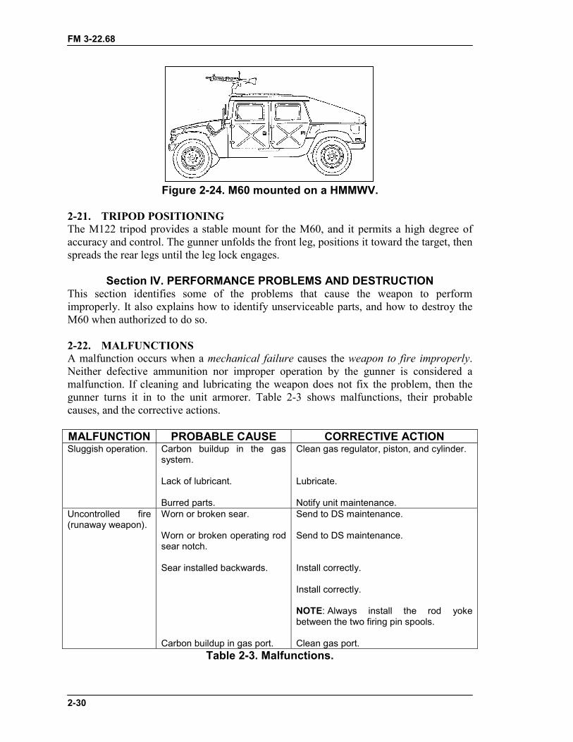
FM 3-22.68
2-30
Figure 2-24. M60 mounted on a HMMWV.
2-21. TRIPOD POSITIONINGThe M122 tripod provides a stable mount for the M60, and it permits a high degree ofaccuracy and control. The gunner unfolds the front leg, positions it toward the target, thenspreads the rear legs until the leg lock engages.
Section IV. PERFORMANCE PROBLEMS AND DESTRUCTIONThis section identifies some of the problems that cause the weapon to performimproperly. It also explains how to identify unserviceable parts, and how to destroy theM60 when authorized to do so.
2-22. MALFUNCTIONSA malfunction occurs when a mechanical failure causes the weapon to fire improperly.Neither defective ammunition nor improper operation by the gunner is considered amalfunction. If cleaning and lubricating the weapon does not fix the problem, then thegunner turns it in to the unit armorer. Table 2-3 shows malfunctions, their probablecauses, and the corrective actions.
MALFUNCTION PROBABLE CAUSE CORRECTIVE ACTIONSluggish operation. Carbon buildup in the gas
system.
Lack of lubricant.
Burred parts.
Clean gas regulator, piston, and cylinder.
Lubricate.
Notify unit maintenance.Uncontrolled fire(runaway weapon).
Worn or broken sear.
Worn or broken operating rodsear notch.
Sear installed backwards.
Carbon buildup in gas port.
Send to DS maintenance.
Send to DS maintenance.
Install correctly.
Install correctly.
NOTE: Always install the rod yokebetween the two firing pin spools.
Clean gas port.Table 2-3. Malfunctions.
FM 3-22.68
2-31
2-23. STOPPAGESA stoppage is any interruption in the cycle of functioning caused by faulty action of theweapon or faulty ammunition. Stoppages are classified by their relationship to the cycleof functioning. Table 2-4 shows types of interruptions or stoppages, their probablecauses, and the corrective actions.
STOPPAGE PROBABLE CAUSE CORRECTIVE ACTIONFailure to chamber. Ruptured cartridge case.
Carbon buildup in gas cylinder.
Carbon buildup in receiver.
Damaged round.
Dirty chamber.
Weak or short operating rod.
Remove cartridge IAWTM 9-1005-224-10.
Remove carbon.
Remove carbon.
Remove round and reload gun.
Clear barrel and clean and lubricateas required.
Replace.Failure to lock. Weak or short operating rod
spring.
Foreign matter in chamber ofreceiver.
Replace.
Clean and lubricate as required.
Failure to fire. Faulty ammunition.
Broken or damaged firing pin orfiring pin spring.
Defective trigger.
Broken or deformed sear plungeror spring.
Failure to lock.
Replace.
Replace.
Send to DS maintenance.
Send to DS maintenance.
See “Failure to Lock.”Failure to extract. Gas piston installed backwards.
Broken extractor spring.
Chipped or broken extractor.
Defective extractor plunger.
Short recoil.
Install properly IAWTM 9-1005-224-10.
Replace.
Replace.
Replace.
Clean gas port and operating rodtube, and lubricate as required.Replace operating rod spring.
Table 2-4. Stoppages.
FM 3-22.68
2-32
STOPPAGE PROBABLE CAUSE CORRECTIVE ACTIONFailure to cock. Broken sear.
Worn operating rod sear notch.
Broken, defective, or missing searplunger or spring.
Short recoil.
Send to DS maintenance.
Send to DS maintenance.
Send to DS maintenance.
Clean gas port and operating rodtube, and lubricate as required.Replace operating rod spring.
Table 2-4. Stoppages (continued).
NOTE: When applying immediate or remedial action on a cold or hot gun, if any partof the round (ranging from the tip of the bullet to the rim) is in the chamber,the gunner removes the ammunition from the feed tray only, then closes thecover and attempts to fire. If the weapon fires, he reloads and continues firing.If it does not fire, he clears the weapon (removes the round using a clearingrod with the cover closed, not using anything other than a clearing rod), thenhe inspects the weapon and ammunition.
2-24. IMMEDIATE ACTIONImmediate action is action taken to reduce a stoppage without looking for the cause.Immediate action should be taken in the event of either a misfire or a cookoff. A misfireis the failure of a chambered round to fire. Such failure can be due to an ammunitiondefect or faulty firing mechanism. A cookoff is the firing of a round caused by the heat ofa hot barrel and not by the firing mechanism. A cookoff can be avoided by applyingimmediate action within 10 seconds after a failure to fire. If the M60 stops firing, the
DANGERS1. IF NOTHING IS EJECTED AND THE WEAPON IS HOT (200 OR
MORE ROUNDS FIRED IN LESS THAN 2 MINUTES), DO NOTOPEN THE COVER. MOVE THE SAFETY TO “S”, WHICHPLACES THE WEAPON ON “S”. KEEP THE WEAPON POINTEDDOWNRANGE AND KEEP AWAY FROM THE WEAPON FOR 15MINUTES, THEN CLEAR THE WEAPON.
2. BE CAREFUL IN CLEARING THE WEAPON WHEN THE BARRELIS HOT, A ROUND MAY FIRE (COOK OFF) DUE TO THEBARREL’S HEAT INSTEAD OF DUE TO THE FIRINGMECHANISM. DURING TRAINING OR ON A FIRING RANGE,AFTER THE WEAPON HAS FIRED 200 ROUNDS, ITS BARREL ISCONSIDERED A HOT BARREL.
3. DURING COMBAT, WAIT 5 SECONDS, BECAUSE OF THEPOSSIBILITY OF A “HANGFIRE,” BEFORE APPLYINGIMMEDIATE AND REMEDIAL ACTION. DURING TRAINING, WAIT15 MINUTES BEFORE CLEARING A HOT WEAPON ANDAPPLYING IMMEDIATE OR REMEDIAL ACTION.
FM 3-22.68
2-33
gunner performs the following immediate actions. An effective memory aid is POPP,which stands for Pull, Observe, Push, and Press:
a. Pulls and locks the cocking handle to the rear while observing the ejection port tosee if a cartridge case, belt link, or round is ejected. Ensures that the bolt remains to therear to prevent double feeding if a round or cartridge case is not ejected.
b. If a cartridge case, belt link, or a round is ejected, returns the cocking handle tothe forward position, aims on the target, and presses the trigger. If the weapon still doesnot fire, takes remedial action. If a cartridge case, belt link, or round is not ejected, takesremedial action.
2-25. REMEDIAL ACTIONRemedial action is any action taken to determine the cause of a stoppage and to restorethe weapon to an operational condition. This action is taken only after immediate actionfails to remedy the problem.
a. Cold Weapon Procedures. When a stoppage occurs with a cold weapon andimmediate action has failed, the gunner uses the following procedures:
(1) Pulls the cocking handle to the rear, locking the bolt. Moves the safety to “S” andreturns the cocking handle.
(2) Places the weapon on the ground or away from his face, opens the cover, andperforms the four-point safety check. Reloads and continues to fire.
(3) If the weapon does not fire, clears the weapon and inspects it and the ammunition.b. Hot Weapon Procedures. If the stoppage occurs with a hot weapon (200 rounds
or more fired in 2 minutes or noted as previously for training), the gunner moves thesafety to “S”, waits 5 seconds (during training, lets the weapon cool for 15 minutes), thenuses the same procedures as outlined for cold weapon procedures.
c. Jammed Cocking Handle. If a stoppage occurs and the cocking handle cannot bepulled to the rear by hand (the bolt may be fully forward and locked or only partiallyforward), the gunner takes the following steps:
(1) Tries once again to pull the cocking handle by hand.
(2) If the weapon is hot enough to cause a cookoff, moves all soldiers a safe distancefrom the weapon and keeps them away for 15 minutes.
(3) After the gun has cooled, opens the cover and disassembles the gun. Ensuresrearward pressure is kept on the cocking handle until the buffer is removed.(The assistant gunner helps the gunner do this.)
(4) Removes the round or fired cartridge. Uses cleaning rod or ruptured cartridgeextractor if necessary.
(a) In a training situation, after completing the remedial action procedures, the gunnerdoes not fire the weapon until it has been inspected by an ordnance specialist.
CAUTIONDo not try to force the cocking handle to the rear with your footor a heavy object. This could damage the weapon.
FM 3-22.68
2-34
(b) In a combat situation, after the stoppage has been corrected, the gunner changesthe barrel and tries to fire. If the weapon fails to function properly, the gunner sends it tothe unit armorer.
2-26. DESTRUCTION PROCEDURESDestruction of any military weapon is only authorized as a last resort to prevent enemycapture or use. This paragraph discusses the field-expedient means of this destruction; itdoes not replace published policies. In combat situations, the commander has theauthority to destroy weapons, but he must report this destruction through channels.
a. Disassemble the weapon as completely as time permits. Use the barrel or tripodmount to destroy the bolt, buffer, and operating rod group, barrels, rear and front sights,and mounts.
b. Bury the disassembled weapon or dump the parts into a stream, a sump,or a latrine.
c. Burn the weapon by placing an incendiary grenade on the receiver group over thebolt (with the cover resting on the grenade) and detonating the grenade.
d. Smash the T&E mechanism and pintle assembly. Bend the tripod legs.
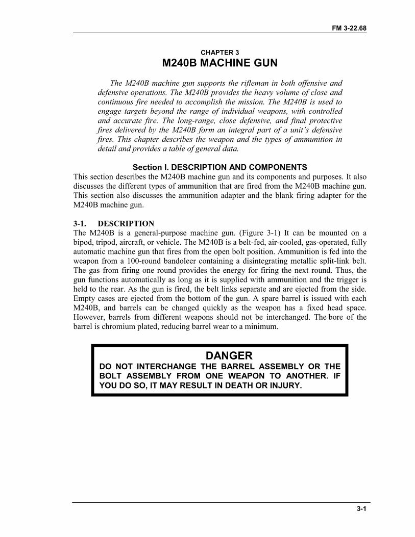
FM 3-22.68
3-1
CHAPTER 3M240B MACHINE GUN
The M240B machine gun supports the rifleman in both offensive anddefensive operations. The M240B provides the heavy volume of close andcontinuous fire needed to accomplish the mission. The M240B is used toengage targets beyond the range of individual weapons, with controlledand accurate fire. The long-range, close defensive, and final protectivefires delivered by the M240B form an integral part of a unit’s defensivefires. This chapter describes the weapon and the types of ammunition indetail and provides a table of general data.
Section I. DESCRIPTION AND COMPONENTSThis section describes the M240B machine gun and its components and purposes. It alsodiscusses the different types of ammunition that are fired from the M240B machine gun.This section also discusses the ammunition adapter and the blank firing adapter for theM240B machine gun.
3-1. DESCRIPTIONThe M240B is a general-purpose machine gun. (Figure 3-1) It can be mounted on abipod, tripod, aircraft, or vehicle. The M240B is a belt-fed, air-cooled, gas-operated, fullyautomatic machine gun that fires from the open bolt position. Ammunition is fed into theweapon from a 100-round bandoleer containing a disintegrating metallic split-link belt.The gas from firing one round provides the energy for firing the next round. Thus, thegun functions automatically as long as it is supplied with ammunition and the trigger isheld to the rear. As the gun is fired, the belt links separate and are ejected from the side.Empty cases are ejected from the bottom of the gun. A spare barrel is issued with eachM240B, and barrels can be changed quickly as the weapon has a fixed head space.However, barrels from different weapons should not be interchanged. The bore of thebarrel is chromium plated, reducing barrel wear to a minimum.
DANGERDO NOT INTERCHANGE THE BARREL ASSEMBLY OR THEBOLT ASSEMBLY FROM ONE WEAPON TO ANOTHER. IFYOU DO SO, IT MAY RESULT IN DEATH OR INJURY.
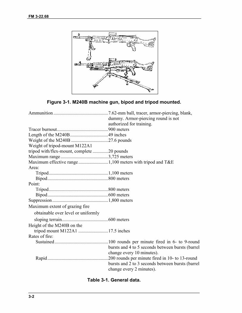
FM 3-22.68
3-2
Figure 3-1. M240B machine gun, bipod and tripod mounted.
Ammunition ..............................................7.62-mm ball, tracer, armor-piercing, blank,dummy. Armor-piercing round is notauthorized for training.
Tracer burnout...........................................900 metersLength of the M240B................................49 inchesWeight of the M240B ...............................27.6 poundsWeight of tripod-mount M122A1tripod with/flex-mount, complete .............20 poundsMaximum range ........................................3,725 metersMaximum effective range .........................1,100 meters with tripod and T&EArea:
Tripod..................................................1,100 metersBipod...................................................800 meters
Point:Tripod..................................................800 metersBipod...................................................600 meters
Suppression ...............................................1,800 metersMaximum extent of grazing fire
obtainable over level or uniformlysloping terrain.......................................600 meters
Height of the M240B on thetripod mount M122A1 .........................17.5 inches
Rates of fire:Sustained .............................................100 rounds per minute fired in 6- to 9-round
bursts and 4 to 5 seconds between bursts (barrelchange every 10 minutes).
Rapid ...................................................200 rounds per minute fired in 10- to 13-roundbursts and 2 to 3 seconds between bursts (barrelchange every 2 minutes).
Table 3-1. General data.
FM 3-22.68
3-3
Cyclic ........................................................650 to 950 rounds per minute in continuousbursts (barrel change every minute).
Basic load of ammunition(three-man crew) ..................................900 to 1200 rounds.
Elevation, tripod controlled ......................+247 milsElevation, tripod free ................................+300 milsDepression, tripod controlled....................-200 milsTraverse, controlled by T&E
mechanism............................................100 milsNormal sector of fire
(with tripod) .........................................875 milsFree gun ....................................................6,400 mils
Table 3-1. General data (continued).
3-2. COMPONENTSThe components of the M240B machine gun and their purpose are shown in Table 3-2and Figure 3-2, page 3-4.
COMPONENTS PURPOSES
(1) Barrel assembly. Consists of the barrel, flash suppressor, carrying handle,heat shield, front sight assembly, and gas-regulator plug.Houses the cartridge for firing and directs the projectile.
(2) Heat shield assembly. Protects the gunner’s hand from a hot barrel.
(3) Buttstock/buffer assemblyand buffer and spade gripassembly/buttstock andbuffer assembly.
Composite buttstock: buffer housing that contains springwashers to absorb recoil from bolt and operating rodassembly at the end of recoil movement.
(4) Receiver assembly. Consists of receiver, handguard, bipod, and rear sightassembly. Serves as support for all major components.Houses action of the weapon and, through a series of camways, controls function of weapon.
(5) Handguard assembly(not shown).
Provides thermal insulation to protect the gunner’s handsfrom heat or extreme cold.
(6) Cocking handle assembly. Pulls the moving parts rearward. Moves in a guide rail fixedto the right side of the receiver.
(7) Trigger housing assembly. Controls the firing of the machine gun. Contains trigger andsafety components
(8) Sling and snap hookassembly.
Provides a means of carrying the weapon.
(9) Bipod. Supports M240B machine gun in prone position.
Table 3-2. Components and purposes.
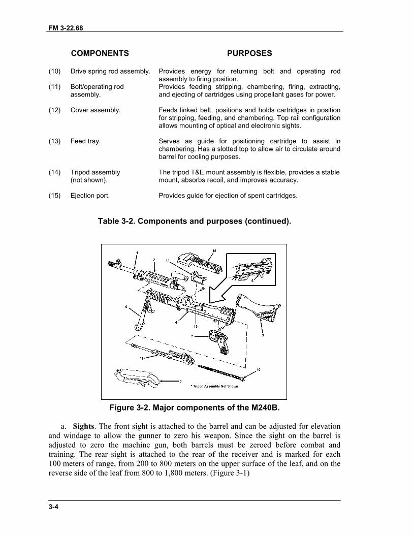
FM 3-22.68
3-4
COMPONENTS PURPOSES
(10) Drive spring rod assembly. Provides energy for returning bolt and operating rodassembly to firing position.
(11) Bolt/operating rodassembly.
Provides feeding stripping, chambering, firing, extracting,and ejecting of cartridges using propellant gases for power.
(12) Cover assembly. Feeds linked belt, positions and holds cartridges in positionfor stripping, feeding, and chambering. Top rail configurationallows mounting of optical and electronic sights.
(13) Feed tray. Serves as guide for positioning cartridge to assist inchambering. Has a slotted top to allow air to circulate aroundbarrel for cooling purposes.
(14) Tripod assembly(not shown).
The tripod T&E mount assembly is flexible, provides a stablemount, absorbs recoil, and improves accuracy.
(15) Ejection port. Provides guide for ejection of spent cartridges.
Table 3-2. Components and purposes (continued).
Figure 3-2. Major components of the M240B.
a. Sights. The front sight is attached to the barrel and can be adjusted for elevationand windage to allow the gunner to zero his weapon. Since the sight on the barrel isadjusted to zero the machine gun, both barrels must be zeroed before combat andtraining. The rear sight is attached to the rear of the receiver and is marked for each100 meters of range, from 200 to 800 meters on the upper surface of the leaf, and on thereverse side of the leaf from 800 to 1,800 meters. (Figure 3-1)
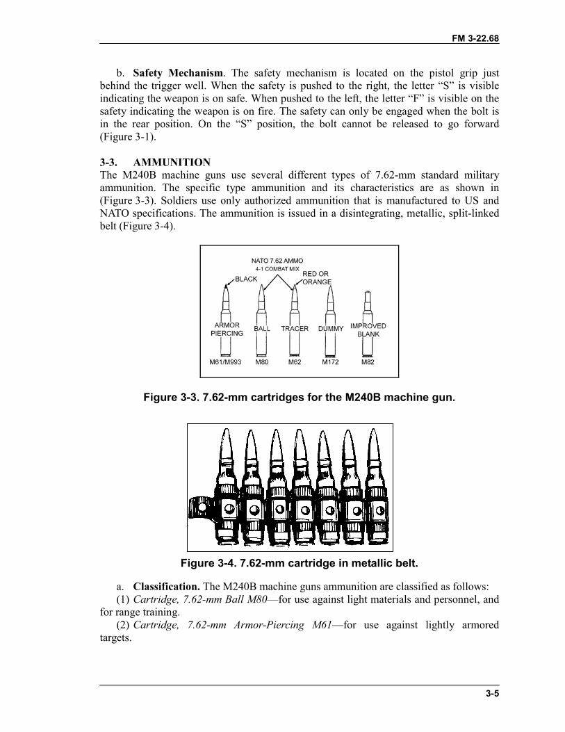
FM 3-22.68
3-5
b. Safety Mechanism. The safety mechanism is located on the pistol grip justbehind the trigger well. When the safety is pushed to the right, the letter “S” is visibleindicating the weapon is on safe. When pushed to the left, the letter “F” is visible on thesafety indicating the weapon is on fire. The safety can only be engaged when the bolt isin the rear position. On the “S” position, the bolt cannot be released to go forward(Figure 3-1).
3-3. AMMUNITIONThe M240B machine guns use several different types of 7.62-mm standard militaryammunition. The specific type ammunition and its characteristics are as shown in(Figure 3-3). Soldiers use only authorized ammunition that is manufactured to US andNATO specifications. The ammunition is issued in a disintegrating, metallic, split-linkedbelt (Figure 3-4).
Figure 3-3. 7.62-mm cartridges for the M240B machine gun.
Figure 3-4. 7.62-mm cartridge in metallic belt.
a. Classification. The M240B machine guns ammunition are classified as follows:(1) Cartridge, 7.62-mm Ball M80—for use against light materials and personnel, and
for range training.(2) Cartridge, 7.62-mm Armor-Piercing M61—for use against lightly armored
targets.
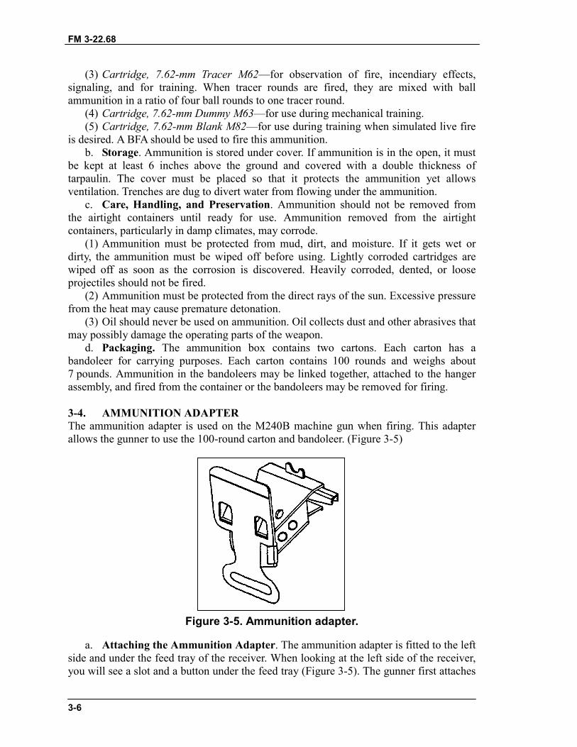
FM 3-22.68
3-6
(3) Cartridge, 7.62-mm Tracer M62—for observation of fire, incendiary effects,signaling, and for training. When tracer rounds are fired, they are mixed with ballammunition in a ratio of four ball rounds to one tracer round.
(4) Cartridge, 7.62-mm Dummy M63—for use during mechanical training.(5) Cartridge, 7.62-mm Blank M82—for use during training when simulated live fire
is desired. A BFA should be used to fire this ammunition.b. Storage. Ammunition is stored under cover. If ammunition is in the open, it must
be kept at least 6 inches above the ground and covered with a double thickness oftarpaulin. The cover must be placed so that it protects the ammunition yet allowsventilation. Trenches are dug to divert water from flowing under the ammunition.
c. Care, Handling, and Preservation. Ammunition should not be removed fromthe airtight containers until ready for use. Ammunition removed from the airtightcontainers, particularly in damp climates, may corrode.
(1) Ammunition must be protected from mud, dirt, and moisture. If it gets wet ordirty, the ammunition must be wiped off before using. Lightly corroded cartridges arewiped off as soon as the corrosion is discovered. Heavily corroded, dented, or looseprojectiles should not be fired.
(2) Ammunition must be protected from the direct rays of the sun. Excessive pressurefrom the heat may cause premature detonation.
(3) Oil should never be used on ammunition. Oil collects dust and other abrasives thatmay possibly damage the operating parts of the weapon.
d. Packaging. The ammunition box contains two cartons. Each carton has abandoleer for carrying purposes. Each carton contains 100 rounds and weighs about7 pounds. Ammunition in the bandoleers may be linked together, attached to the hangerassembly, and fired from the container or the bandoleers may be removed for firing.
3-4. AMMUNITION ADAPTERThe ammunition adapter is used on the M240B machine gun when firing. This adapterallows the gunner to use the 100-round carton and bandoleer. (Figure 3-5)
Figure 3-5. Ammunition adapter.
a. Attaching the Ammunition Adapter. The ammunition adapter is fitted to the leftside and under the feed tray of the receiver. When looking at the left side of the receiver,you will see a slot and a button under the feed tray (Figure 3-5). The gunner first attaches
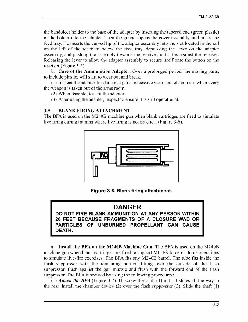
FM 3-22.68
3-7
the bandoleer holder to the base of the adapter by inserting the tapered end (green plastic)of the holder into the adapter. Then the gunner opens the cover assembly, and raises thefeed tray. He inserts the curved lip of the adapter assembly into the slot located in the railon the left of the receiver, below the feed tray, depressing the lever on the adapterassembly, and pushing the assembly towards the receiver, until it is against the receiver.Releasing the lever to allow the adapter assembly to secure itself onto the button on thereceiver (Figure 3-5).
b. Care of the Ammunition Adapter. Over a prolonged period, the moving parts,to include plastic, will start to wear out and break.
(1) Inspect the adapter for damaged parts, excessive wear, and cleanliness when everythe weapon is taken out of the arms room.
(2) When feasible, test-fit the adapter.(3) After using the adapter, inspect to ensure it is still operational.
3-5. BLANK FIRING ATTACHMENTThe BFA is used on the M240B machine gun when blank cartridges are fired to simulatelive firing during training where live firing is not practical (Figure 3-6).
Figure 3-6. Blank firing attachment.
a. Install the BFA on the M240B Machine Gun. The BFA is used on the M240Bmachine gun when blank cartridges are fired to support MILES force-on-force operationsto simulate live-fire exercises. The BFA fits any M240B barrel. The tube fits inside theflash suppressor with the remaining portion fitting over the outside of the flashsuppressor, flush against the gun muzzle and flush with the forward end of the flashsuppressor. The BFA is secured by using the following procedures:
(1) Attach the BFA (Figure 3-7). Unscrew the shaft (1) until it slides all the way tothe rear. Install the chamber device (2) over the flash suppressor (3). Slide the shaft (1)
DANGERDO NOT FIRE BLANK AMMUNITION AT ANY PERSON WITHIN20 FEET BECAUSE FRAGMENTS OF A CLOSURE WAD ORPARTICLES OF UNBURNED PROPELLANT CAN CAUSEDEATH.
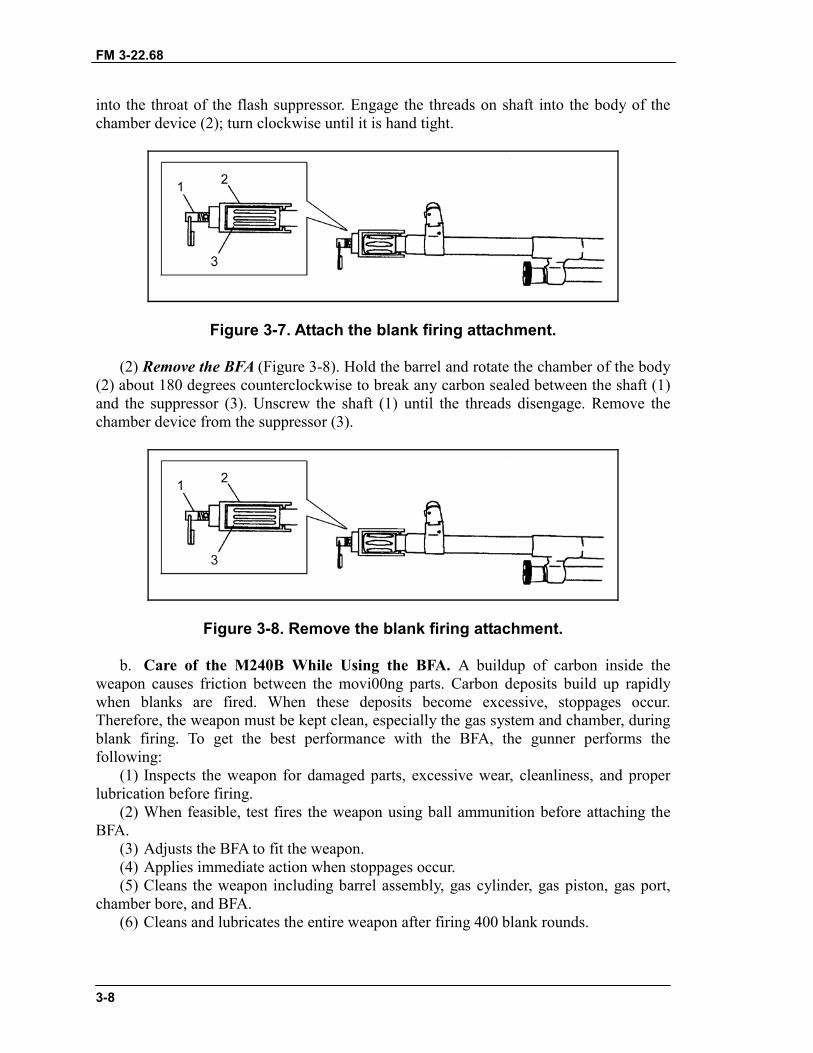
FM 3-22.68
3-8
into the throat of the flash suppressor. Engage the threads on shaft into the body of thechamber device (2); turn clockwise until it is hand tight.
Figure 3-7. Attach the blank firing attachment.
(2) Remove the BFA (Figure 3-8). Hold the barrel and rotate the chamber of the body(2) about 180 degrees counterclockwise to break any carbon sealed between the shaft (1)and the suppressor (3). Unscrew the shaft (1) until the threads disengage. Remove thechamber device from the suppressor (3).
Figure 3-8. Remove the blank firing attachment.
b. Care of the M240B While Using the BFA. A buildup of carbon inside theweapon causes friction between the movi00ng parts. Carbon deposits build up rapidlywhen blanks are fired. When these deposits become excessive, stoppages occur.Therefore, the weapon must be kept clean, especially the gas system and chamber, duringblank firing. To get the best performance with the BFA, the gunner performs thefollowing:
(1) Inspects the weapon for damaged parts, excessive wear, cleanliness, and properlubrication before firing.
(2) When feasible, test fires the weapon using ball ammunition before attaching theBFA.
(3) Adjusts the BFA to fit the weapon.(4) Applies immediate action when stoppages occur.(5) Cleans the weapon including barrel assembly, gas cylinder, gas piston, gas port,
chamber bore, and BFA.(6) Cleans and lubricates the entire weapon after firing 400 blank rounds.
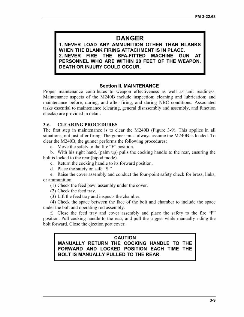
FM 3-22.68
3-9
Section II. MAINTENANCEProper maintenance contributes to weapon effectiveness as well as unit readiness.Maintenance aspects of the M240B include inspection; cleaning and lubrication; andmaintenance before, during, and after firing, and during NBC conditions. Associatedtasks essential to maintenance (clearing, general disassembly and assembly, and functionchecks) are provided in detail.
3-6. CLEARING PROCEDURESThe first step in maintenance is to clear the M240B (Figure 3-9). This applies in allsituations, not just after firing. The gunner must always assume the M240B is loaded. Toclear the M240B, the gunner performs the following procedures:
a. Move the safety to the fire “F” position.b. With his right hand, (palm up) pulls the cocking handle to the rear, ensuring the
bolt is locked to the rear (bipod mode).c. Return the cocking handle to its forward position.d. Place the safety on safe “S.”e. Raise the cover assembly and conduct the four-point safety check for brass, links,
or ammunition.(1) Check the feed pawl assembly under the cover.(2) Check the feed tray.(3) Lift the feed tray and inspects the chamber.(4) Check the space between the face of the bolt and chamber to include the space
under the bolt and operating rod assembly.f. Close the feed tray and cover assembly and place the safety to the fire “F”
position. Pull cocking handle to the rear, and pull the trigger while manually riding thebolt forward. Close the ejection port cover.
DANGER1. NEVER LOAD ANY AMMUNITION OTHER THAN BLANKSWHEN THE BLANK FIRING ATTACHMENT IS IN PLACE.2. NEVER FIRE THE BFA-FITTED MACHINE GUN ATPERSONNEL WHO ARE WITHIN 20 FEET OF THE WEAPON.DEATH OR INJURY COULD OCCUR.
CAUTIONMANUALLY RETURN THE COCKING HANDLE TO THEFORWARD AND LOCKED POSITION EACH TIME THEBOLT IS MANUALLY PULLED TO THE REAR.
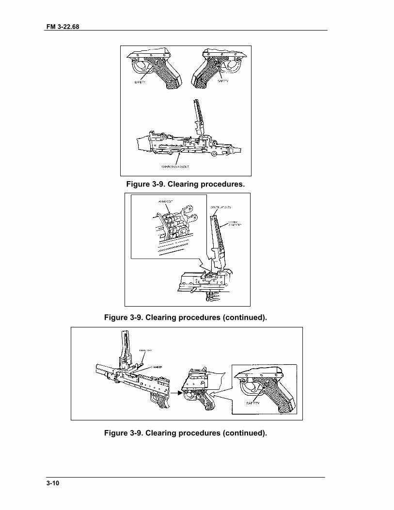
FM 3-22.68
3-10
Figure 3-9. Clearing procedures.
Figure 3-9. Clearing procedures (continued).
Figure 3-9. Clearing procedures (continued).
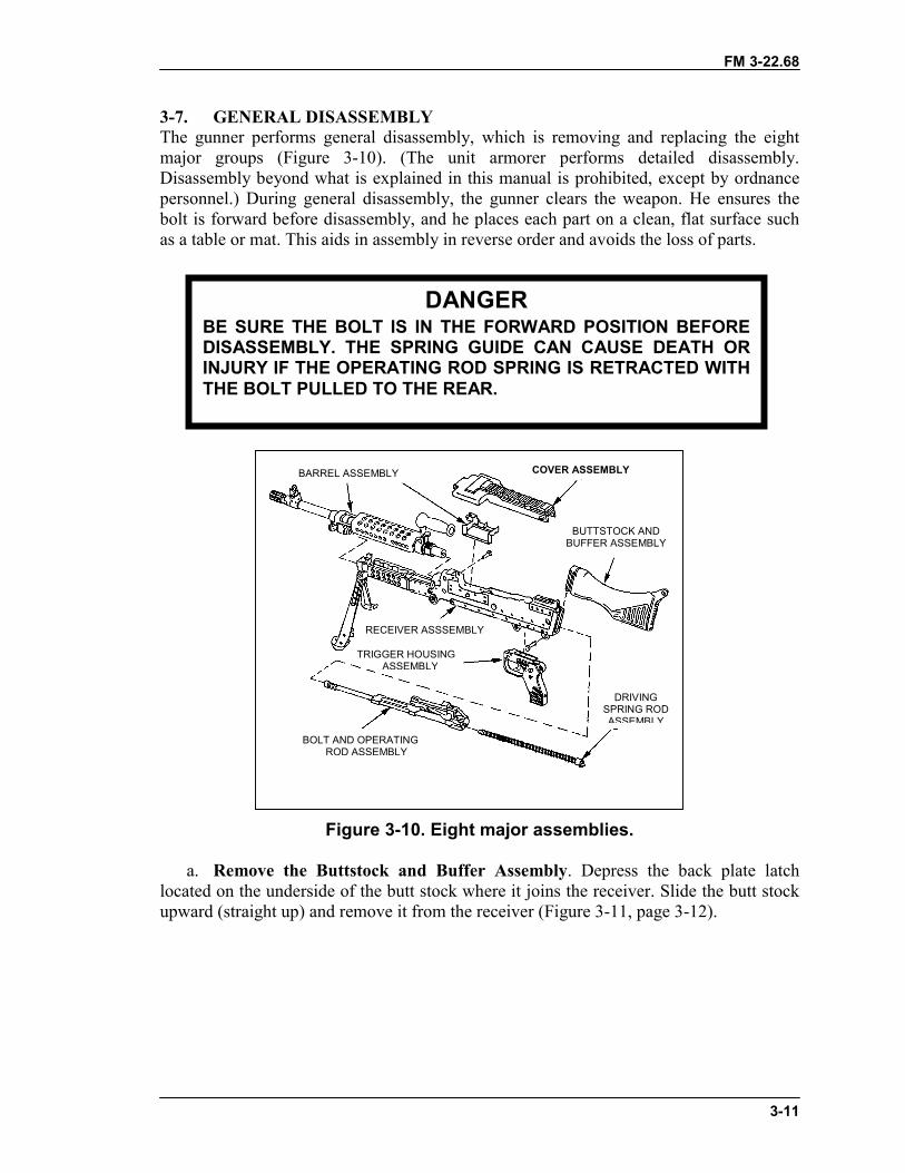
FM 3-22.68
3-11
3-7. GENERAL DISASSEMBLYThe gunner performs general disassembly, which is removing and replacing the eightmajor groups (Figure 3-10). (The unit armorer performs detailed disassembly.Disassembly beyond what is explained in this manual is prohibited, except by ordnancepersonnel.) During general disassembly, the gunner clears the weapon. He ensures thebolt is forward before disassembly, and he places each part on a clean, flat surface suchas a table or mat. This aids in assembly in reverse order and avoids the loss of parts.
Figure 3-10. Eight major assemblies.
a. Remove the Buttstock and Buffer Assembly. Depress the back plate latchlocated on the underside of the butt stock where it joins the receiver. Slide the butt stockupward (straight up) and remove it from the receiver (Figure 3-11, page 3-12).
DANGERBE SURE THE BOLT IS IN THE FORWARD POSITION BEFOREDISASSEMBLY. THE SPRING GUIDE CAN CAUSE DEATH ORINJURY IF THE OPERATING ROD SPRING IS RETRACTED WITHTHE BOLT PULLED TO THE REAR.
COVER ASSEMBLY
BUTTSTOCK ANDBUFFER ASSEMBLY
BARREL ASSEMBLY
BOLT AND OPERATINGROD ASSEMBLY
RECEIVER ASSSEMBLY
TRIGGER HOUSINGASSEMBLY
DRIVINGSPRING RODASSEMBLY
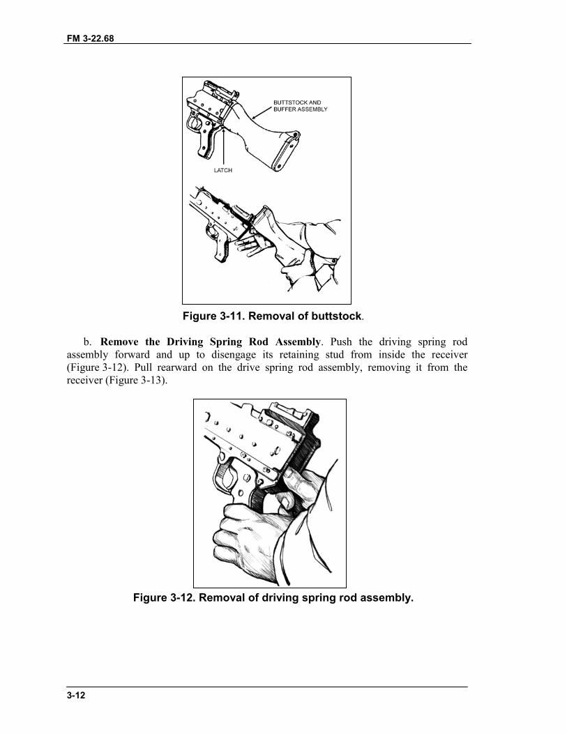
FM 3-22.68
3-12
Figure 3-11. Removal of buttstock.
b. Remove the Driving Spring Rod Assembly. Push the driving spring rodassembly forward and up to disengage its retaining stud from inside the receiver(Figure 3-12). Pull rearward on the drive spring rod assembly, removing it from thereceiver (Figure 3-13).
Figure 3-12. Removal of driving spring rod assembly.
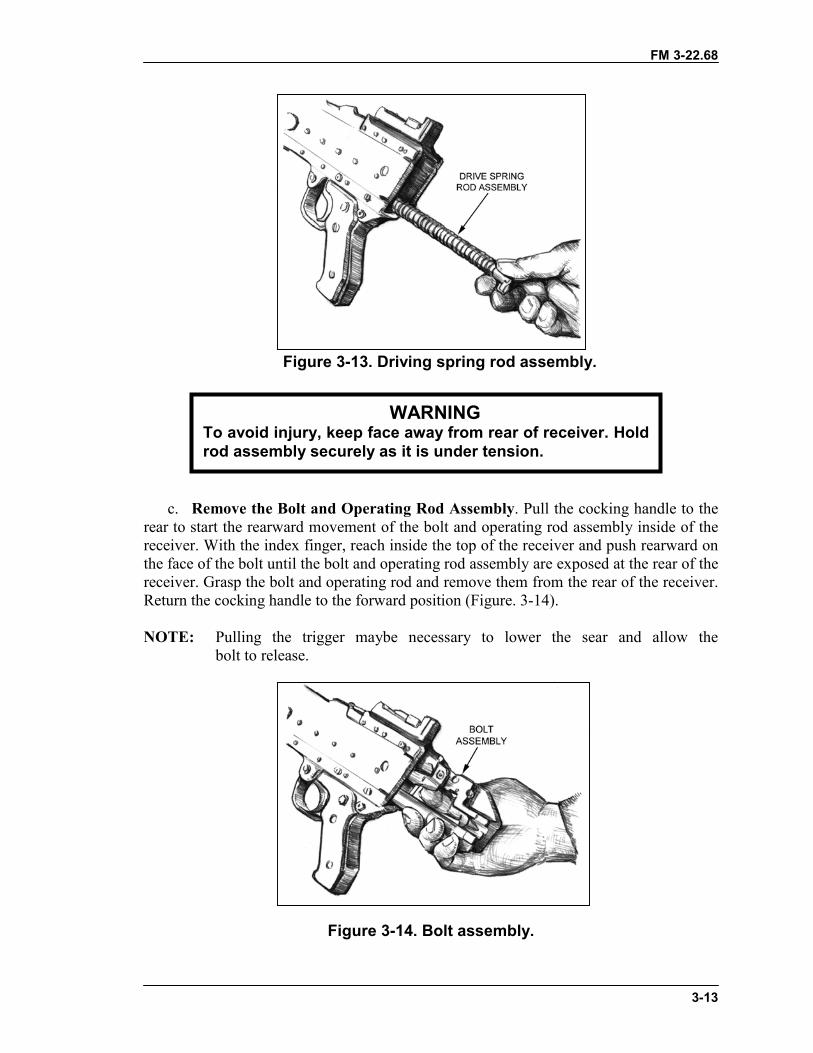
FM 3-22.68
3-13
Figure 3-13. Driving spring rod assembly.
c. Remove the Bolt and Operating Rod Assembly. Pull the cocking handle to therear to start the rearward movement of the bolt and operating rod assembly inside of thereceiver. With the index finger, reach inside the top of the receiver and push rearward onthe face of the bolt until the bolt and operating rod assembly are exposed at the rear of thereceiver. Grasp the bolt and operating rod and remove them from the rear of the receiver.Return the cocking handle to the forward position (Figure. 3-14).
NOTE: Pulling the trigger maybe necessary to lower the sear and allow thebolt to release.
Figure 3-14. Bolt assembly.
WARNINGTo avoid injury, keep face away from rear of receiver. Holdrod assembly securely as it is under tension.
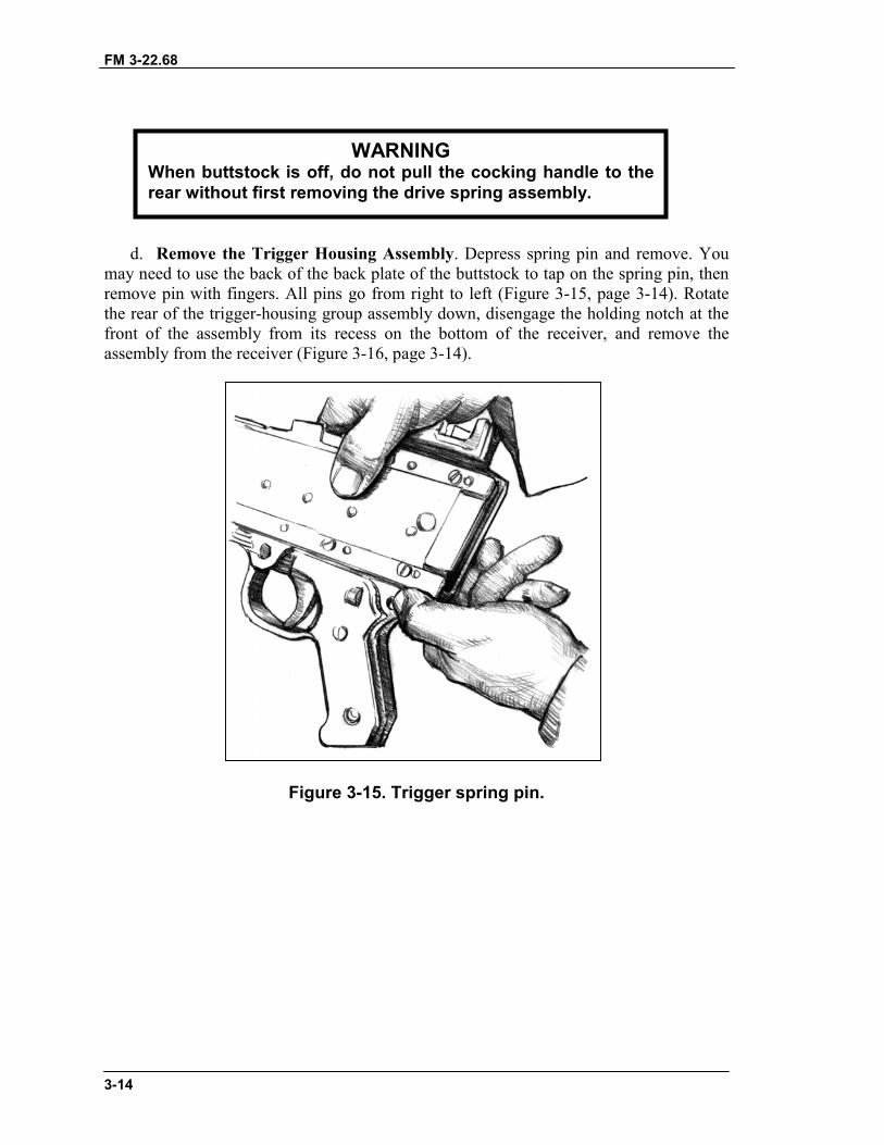
FM 3-22.68
3-14
d. Remove the Trigger Housing Assembly. Depress spring pin and remove. Youmay need to use the back of the back plate of the buttstock to tap on the spring pin, thenremove pin with fingers. All pins go from right to left (Figure 3-15, page 3-14). Rotatethe rear of the trigger-housing group assembly down, disengage the holding notch at thefront of the assembly from its recess on the bottom of the receiver, and remove theassembly from the receiver (Figure 3-16, page 3-14).
Figure 3-15. Trigger spring pin.
WARNINGWhen buttstock is off, do not pull the cocking handle to therear without first removing the drive spring assembly.
FM 3-22.68
3-15
Figure 3-16. Removal of trigger housing.
e. Remove the Cover Assembly. (A) Close cover. Depress spring pin and remove.You may need to use the back of the back plate of the buttstock to tap on the spring pin.(B) Then remove pin with fingers. All pins go from right to left. (C) Depress coverlatches, lift upwards and remove cover assembly. (D) Remove feed tray (Figure 3-17,page 3-16).
FM 3-22.68
3-16
Figure 3-17. Removal of cover, feed tray, and spring pin.
f. Remove the Barrel Assembly. (A) Make sure that the barrel-carrying handle isto the right side. Depress the barrel-locking latch located on the left side of the receiverwhere the barrel joins the receiver and hold. (B) Grasp the barrel carrying handle androtate the carrying handle to the upright position (without pulling up on the barrelrelease). (C) Then push forward and pull up, separating the barrel from the receiver(Figure 3-18).
FM 3-22.68
3-17
Figure 3-18. Removal of barrel.
g. Disassemble the Barrel Assembly. (A) Hold the barrel at the point where the gassystem attaches to it. (B) Grasp and rotate the gas collar clockwise until it releases fromthe gas plug. Remove the collar from the gas plug. (C) Slide the gas regulator plug fromfront to rear, removing it from the gas hole bushing. (D) Remove heat shield. Lift the rearof heat shield assembly off the barrel, then pry one of the front metal tabs out of hole ongas hole bushing, rotate the heat shield towards the other metal tab, and remove heatshield from the barrel. This completes the general disassembly (Figure 3-19, page 3-18).
FM 3-22.68
3-18
Figure 3-19. Gas regulator and collar.
3-8. INSPECTIONInspection begins with the weapon disassembled into its eight major assemblies.Note that a shiny surface on a part does not mean the parts are unserviceable. The gunnerinspects each area of the weapon and related equipment for the conditions indicated. Anybroken or missing parts should be repaired or replaced IAW TM 9-1005-313-10.The gunner should perform PMCS every 90 days. If the weapon has not been used in90 days, the PMCS in the operator’s manual should be performed regardless. If you seerust on a weapon, the PMCS should be done immediately. Inspect all of the componentsfor broken or missing parts. Inspect parts for cracks, dents, burrs excessive wear, rust, orcorrosion. Inspect external surfaces for adequate finish.
a. Barrel Assembly. Check barrel for bulges, bends, burrs, obstructions andobstructions or pits in the chamber or bore. Disassemble, inspect, and clean the gas collarand plug. Ensure the flash suppressor is fastened securely. Inspect the front sight fordamage or looseness. Inspect carrying handle assembly for bent, broken, or missing parts.Assure the heat shield is present, on the barrel assembly, and is not bent or broken, anddoes not have any missing parts.
FM 3-22.68
3-19
NOTE: Some heat distortion or charring may be observed on the outer nonmetallicportion of the heat shield and is not cause for replacement. Do not applylubricants to composite or rubber components.
b. Buttstock and Buffer Assembly. Check for burrs and rough edges on matinggrooves and flanges. Check to be sure the back plate latch locks the buffer assemblysecurely to the receiver assembly when installed. Make sure the buffer plug sticks outthrough the back plate and is flush or higher than the protrusion below it. Make sure thereis no rattling sound when the buffer is shaken and that the plug cannot rotated by fingerpressure. Inspect the butt stock for cracks. Check to make sure the back plate locks thebutt stock securely to the receiver assembly when installed.
c. Driving Spring Rod Assembly. Check the spring for broken strands. Ensure therod assembly is not bent.
d. Bolt And Operating Rod Assembly. Inspect entire area of the bolt and operatingrod assembly for missing parts, broken or cracked areas, burrs, bends, or pits on thesurface. Looking at the bolt, you can see if the firing pin is broken. The extractor shouldnot move. The operating rod piston should have a slight movement from left to right(about 1/8-inch turn). When the bolt and operating rod are pulled to the rear, the pistonshould move freely without binding.
NOTE: Always turn both barrels in with the weapon if damage is found on the boltassembly.
e. Trigger Mechanism/Housing Assembly. Inspect the tripping lever and sear forburrs on edges. Push the tripping lever back to raise the sear, put the safety on “S,” andpull the trigger. The sear should not drop down far enough to lock in the downwardposition. Place the safety on “F,” and pull the trigger. The sear should drop down andlock in the downward position. Check the sear spring, ensuring the leg of the spring isbehind the trigger pin and not between the trigger and the pin. Check grip assembly forloose or missing grip screws. Check trigger guard for bends or cracks. Check triggerspring pin for bends, and or broken or missing spring.
f. Cover Assembly. Pivot the feed lever back and forth to ensure it operatessmoothly without binding. Push in on the cover latches to make sure the retaining clip isnot weak or missing and that they do not bind in the housing. Push down on the cartridgeguides and feed pawls to make sure the springs are not weak or missing. Inspectaccessory mounting rail for nicks or burrs.
g. Feed Tray. Check for cracks, deformation, broken welds, or loose rivets.h. Handguard. Check handguard for cracks, broken or missing parts.i. Receiver Assembly. Check that the rear sight assembly is securely mounted to
the receiver and operates properly. Check that the cocking handle operates the slideproperly. Pull the cocking handle to the rear and allow it to slowly return forward,making sure that the slide does not bind in the receiver. Check for damaged or missingejection port cover, spring, and pin. Lower and raise the bipod legs, ensuring they movefreely without binding. Check bipod legs for cracks, or twisted or incomplete assembly.Check the exterior surface of the M240B for the exterior protective finish.
FM 3-22.68
3-20
j. Machine Gun. Assemble the weapon. Be sure parts are installed correctly and arein good working condition. When installing the barrel, move the barrel release slowly tothe right and count the number of clicks. Fewer than two and more than seven clicksindicate defective parts. Check both barrels. Check weapon functioning with belteddummy ammunition by performing a function check. If weapon does not functionproperly and the cause cannot be determined using troubling shooting procedures, notifydirect-support maintenance.
k. M122A1 Mount. The traversing and elevating mechanism should not bind. Thenumbers on the scales and dials must be legible.
(1) Distinct clicks must be heard when the handwheels are turned. Index lines shouldbe calibrated with the indicator pointer.
(2) The pintle should fit snugly in the pintle bushing, and the pintle lock should holdthe pintle securely.
(3) The sleeve latch should function properly, and the traversing bar should be tightwhen the tripod legs are extended and latched.
l. Carrying Case. Maintenance tools and equipment should be complete andserviceable. The case should be serviceable. Frequent washing of the case should beavoided. Such washing may destroy the waterproofing and shrink the case.
3-9. CLEANING, LUBRICATION, AND PREVENTIVE MAINTENANCEThe M240B machine gun should be cleaned immediately after firing. At a minimum, theM240B should be cleaned after firing a basic load of 900 to 1,200 rounds. The gunnerdisassembles the M240B into its major groups for cleaning. All metal components andsurfaces that have been exposed to powder fouling should be cleaned using CLP on abore-cleaning patch. CLP is used on the bristles of the receiver brush to clean thereceiver. After the M240B is cleaned and wiped dry, a thin coat of CLP is rubbed onusing a cloth. This lubricates and preserves the exposed metal parts during all normaltemperature ranges.
a. When cleaning the weapon, any of the previously mentioned cleaning lubricatingagents can be used. As soon as possible after firing the M240B, the gunner disassemblesthe weapon into its eight major assemblies and cleans them as follows. Before theweapon is disassembled, ensure it is clear:
(1) Clean the bore using CLP or RBC and a bore brush with a cleaning rod. Do notreverse direction of the bore brush while it is in the bore.
(a) Run the brush through the bore several times until most of the powder fouling andother foreign matter has been removed.
(b) Swab out the bore several times using a cleaning rod and a swab wet with CLP.(c) Swab out the bore several times using a cleaning rod and a dry swab.(2) Clean the chamber using CLP and a chamber brush attached to a cleaning rod.
CAUTIONWhen using CLP, do not use other cleaners. Never mixCLP with RBC or LSA. When cleaning the barrel, avoidgetting CLP or RBC in the gas regulator. Damage couldoccur to the weapon.
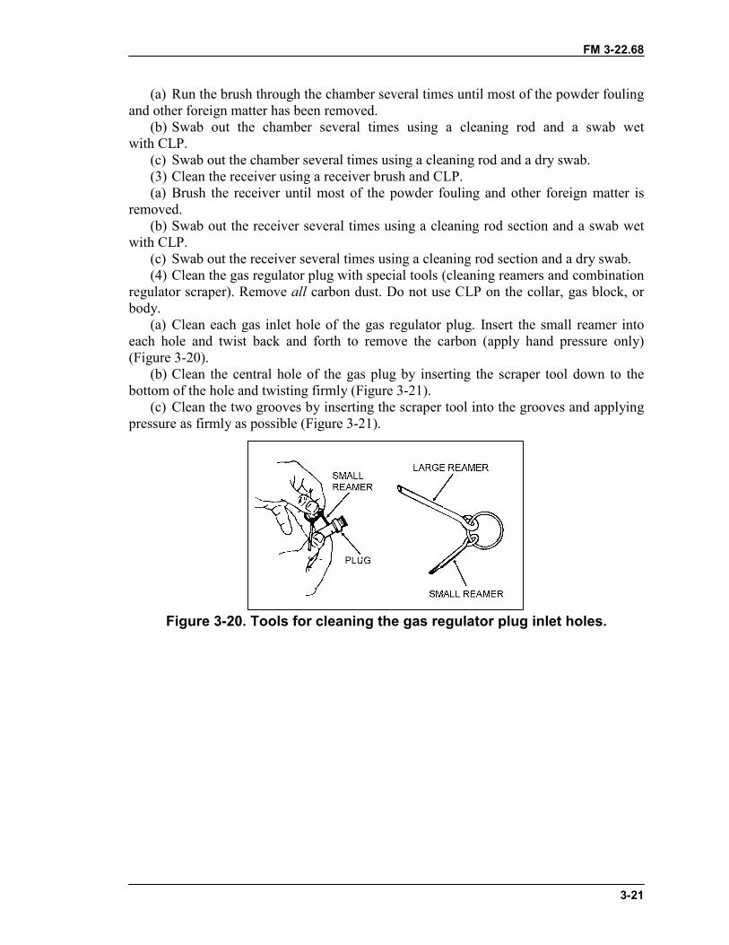
FM 3-22.68
3-21
(a) Run the brush through the chamber several times until most of the powder foulingand other foreign matter has been removed.
(b) Swab out the chamber several times using a cleaning rod and a swab wetwith CLP.
(c) Swab out the chamber several times using a cleaning rod and a dry swab.(3) Clean the receiver using a receiver brush and CLP.(a) Brush the receiver until most of the powder fouling and other foreign matter is
removed.(b) Swab out the receiver several times using a cleaning rod section and a swab wet
with CLP.(c) Swab out the receiver several times using a cleaning rod section and a dry swab.(4) Clean the gas regulator plug with special tools (cleaning reamers and combination
regulator scraper). Remove all carbon dust. Do not use CLP on the collar, gas block, orbody.
(a) Clean each gas inlet hole of the gas regulator plug. Insert the small reamer intoeach hole and twist back and forth to remove the carbon (apply hand pressure only)(Figure 3-20).
(b) Clean the central hole of the gas plug by inserting the scraper tool down to thebottom of the hole and twisting firmly (Figure 3-21).
(c) Clean the two grooves by inserting the scraper tool into the grooves and applyingpressure as firmly as possible (Figure 3-21).
Figure 3-20. Tools for cleaning the gas regulator plug inlet holes.
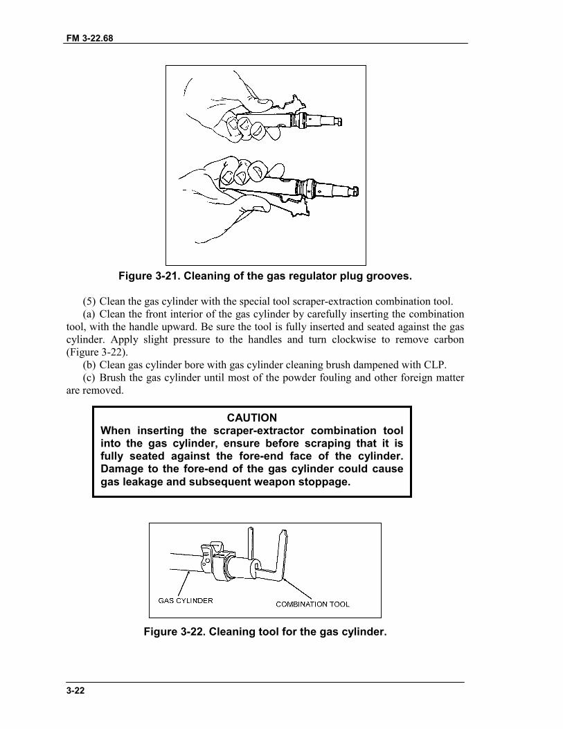
FM 3-22.68
3-22
Figure 3-21. Cleaning of the gas regulator plug grooves.
(5) Clean the gas cylinder with the special tool scraper-extraction combination tool.(a) Clean the front interior of the gas cylinder by carefully inserting the combination
tool, with the handle upward. Be sure the tool is fully inserted and seated against the gascylinder. Apply slight pressure to the handles and turn clockwise to remove carbon(Figure 3-22).
(b) Clean gas cylinder bore with gas cylinder cleaning brush dampened with CLP.(c) Brush the gas cylinder until most of the powder fouling and other foreign matter
are removed.
Figure 3-22. Cleaning tool for the gas cylinder.
CAUTIONWhen inserting the scraper-extractor combination toolinto the gas cylinder, ensure before scraping that it isfully seated against the fore-end face of the cylinder.Damage to the fore-end of the gas cylinder could causegas leakage and subsequent weapon stoppage.
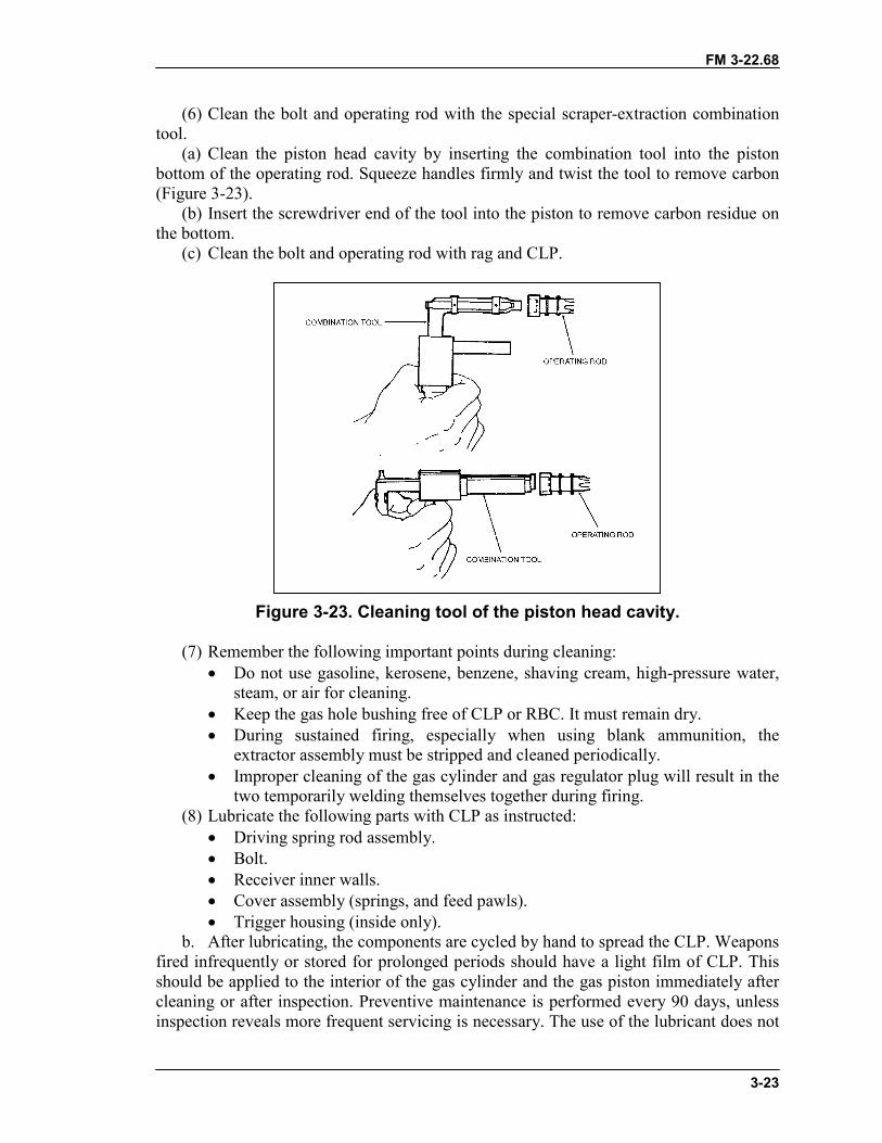
FM 3-22.68
3-23
(6) Clean the bolt and operating rod with the special scraper-extraction combinationtool.
(a) Clean the piston head cavity by inserting the combination tool into the pistonbottom of the operating rod. Squeeze handles firmly and twist the tool to remove carbon(Figure 3-23).
(b) Insert the screwdriver end of the tool into the piston to remove carbon residue onthe bottom.
(c) Clean the bolt and operating rod with rag and CLP.
Figure 3-23. Cleaning tool of the piston head cavity.
(7) Remember the following important points during cleaning:� Do not use gasoline, kerosene, benzene, shaving cream, high-pressure water,
steam, or air for cleaning.� Keep the gas hole bushing free of CLP or RBC. It must remain dry.� During sustained firing, especially when using blank ammunition, the
extractor assembly must be stripped and cleaned periodically.� Improper cleaning of the gas cylinder and gas regulator plug will result in the
two temporarily welding themselves together during firing.(8) Lubricate the following parts with CLP as instructed:
� Driving spring rod assembly.� Bolt.� Receiver inner walls.� Cover assembly (springs, and feed pawls).� Trigger housing (inside only).
b. After lubricating, the components are cycled by hand to spread the CLP. Weaponsfired infrequently or stored for prolonged periods should have a light film of CLP. Thisshould be applied to the interior of the gas cylinder and the gas piston immediately aftercleaning or after inspection. Preventive maintenance is performed every 90 days, unlessinspection reveals more frequent servicing is necessary. The use of the lubricant does not
FM 3-22.68
3-24
eliminate the requirement for cleaning and inspecting to ensure that corrosion has notformed. Before the weapon is used, the gas system and components must be cleaned andfree of oil and lubricants.
c. All exposed surfaces of the M122A1 tripod, flex-mount assembly, complete pintleand T&E mechanism are cleaned by wiping them down with a clean rag. For T&E andpintles that have stubborn areas with hard-to-remove dirt, a steel brush or bore brush isused to loosen the dirt (do not use on the flex-mount itself). A clean rag is then used towipe them down and CLP is used to lubricate them.
d. The following procedures apply to cleaning and lubricating the M240B duringunusual conditions:
(1) Below 0 degrees Fahrenheit—use lubricating oil, arctic weather (LAW). Oillightly to avoid freeze-up.
(2) Extreme heat—use light coat of CLP.(3) Damp or salty air—use CLP. Clean and apply frequently.(4) Sandy or dusty areas—use CLP. Clean and apply frequently. Wipe with rag after
each application to remove excess.
3-10. GENERAL ASSEMBLYAfter cleaning, lubricating, and inspecting the weapon, the gunner assembles the weaponand performs a function check.
a. Replacing the Barrel Assembly. Insert the gas regulator plug into the gas holebushing so that it is on the number one setting. (number 1 gas setting on the regulatorfaces towards the barrel). Place the gas collar over the front end of the gas regulator plug,while pushing against the spring, rotate counterclockwise until it stops. Insert one of themetal tabs of the heat shield in to the hole located of the sides of the gas hole bushing,than rotate it so that the other tab locks in place. Then push down on the heat shield sothat it snaps onto the barrel. With gas regulator downward and carrying handle in thevertical position, place barrel on the barrel support (located on the gas cylinder). Keepingthe gun upright, pull the barrel to the rear ensuring the gas regulator is guided into the gascylinder. Pull the barrel fully into the receiver and rotate the carrying handle completelyto the right, ensuring to count the number of clicks. If the number of clicks fall between 2to 7, the headspace is set correctly. If the number falls outside 2 to 7, turn it in to the unitarmor (make sure that the threads on the barrel are located on top and bottom and on theinside of the receiver make sure that the threads are located on the left and right)(Figure 3-24).
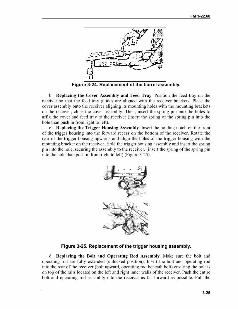
FM 3-22.68
3-25
Figure 3-24. Replacement of the barrel assembly.
b. Replacing the Cover Assembly and Feed Tray. Position the feed tray on thereceiver so that the feed tray guides are aligned with the receiver brackets. Place thecover assembly onto the receiver aligning its mounting holes with the mounting bracketson the receiver, close the cover assembly. Then, insert the spring pin into the holes toaffix the cover and feed tray to the receiver (insert the spring of the spring pin into thehole than push in from right to left).
c. Replacing the Trigger Housing Assembly. Insert the holding notch on the frontof the trigger housing into the forward recess on the bottom of the receiver. Rotate therear of the trigger housing upwards and align the holes of the trigger housing with themounting bracket on the receiver. Hold the trigger housing assembly and insert the springpin into the hole, securing the assembly to the receiver. (insert the spring of the spring pininto the hole than push in from right to left) (Figure 3-25).
Figure 3-25. Replacement of the trigger housing assembly.
d. Replacing the Bolt and Operating Rod Assembly. Make sure the bolt andoperating rod are fully extended (unlocked position). Insert the bolt and operating rodinto the rear of the receiver (bolt upward, operating rod beneath bolt) ensuring the bolt ison top of the rails located on the left and right inner walls of the receiver. Push the entirebolt and operating rod assembly into the receiver as far forward as possible. Pull the
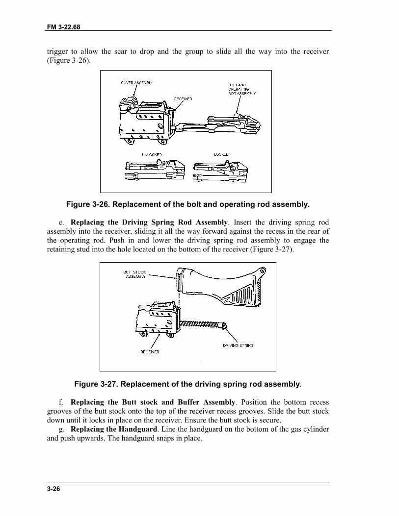
FM 3-22.68
3-26
trigger to allow the sear to drop and the group to slide all the way into the receiver(Figure 3-26).
Figure 3-26. Replacement of the bolt and operating rod assembly.
e. Replacing the Driving Spring Rod Assembly. Insert the driving spring rodassembly into the receiver, sliding it all the way forward against the recess in the rear ofthe operating rod. Push in and lower the driving spring rod assembly to engage theretaining stud into the hole located on the bottom of the receiver (Figure 3-27).
Figure 3-27. Replacement of the driving spring rod assembly.
f. Replacing the Butt stock and Buffer Assembly. Position the bottom recessgrooves of the butt stock onto the top of the receiver recess grooves. Slide the butt stockdown until it locks in place on the receiver. Ensure the butt stock is secure.
g. Replacing the Handguard. Line the handguard on the bottom of the gas cylinderand push upwards. The handguard snaps in place.

FM 3-22.68
3-27
3-11. FUNCTION CHECKThe gunner must perform a function check to ensure that the M240B is correctlyassembled. The procedures, in order, are�
a. Places the safety on “F.”b. Pulls the cocking handle to the rear, locking the bolt to the rear of the receiver.c. Returns the cocking handle to the forward position.d. Places the safety on “S,” and closes the cover.e. Pulls the trigger. (Bolt should not go forward).f. Places the safety on “F.”g. Pulls the cocking handle to the rear, pulls the trigger, and rides the bolt forward.h. Closes the ejection port cover.
3-12. MAINTENANCE PROCEDURESMaintenance of the M240B requires certain actions to be taken before, during, and afterfiring.
a. Before firing�(1) Wipe the bore dry.(2) Inspect the weapon as outlined in operator’s TM.(3) Inspect the spare barrel.(4) Lubricate the weapon.b. During firing—(1) Change the barrels. Changing the barrel prolongs the life of both barrels.(2) Periodically inspect the weapon to ensure that it is properly lubricated.(3) When malfunctions or stoppages occur, follow the procedures in Section IV.c. After firing—(1) Clear and clean the weapon immediately.(2) Every 90 days during inactivity, clean and lubricate the weapon unless inspection
reveals more frequent servicing is necessary (TM 9-1005-313-10).
3-13. MAINTENANCE DURING NUCLEAR, BIOLOGICAL, CHEMICALCONDITIONSIf the M240B is contaminated by chemical, biological, or radiological agents, the gunnertakes appropriate action to reduce exposure and minimize penetration.
a. Chemical. The gunner uses towelettes from the M258A1 kit to wipe off theweapon. If these are not available, he washes the weapon with soap and water.
b. Biological. The gunner uses towelettes or soap and water as previously described.c. Radiological. The gunner wipes the weapon with warm soapy water if it is
available. If not, he uses towelettes or rags. (For more details, see FM 3-5.)
Section III. OPERATION AND FUNCTIONThis section discusses the operation of the M240B machine gun. This includes loading,unloading, cycle of functioning, adjustment of the sights, and use of both the bipod andtripod.
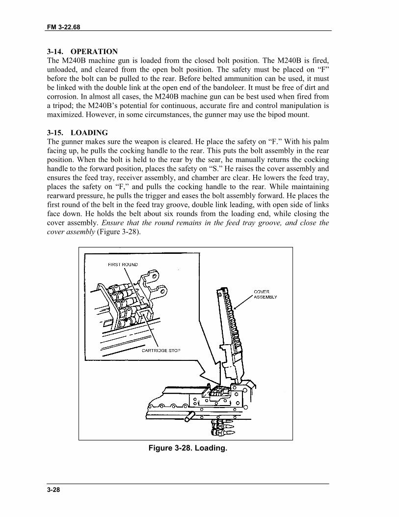
FM 3-22.68
3-28
3-14. OPERATIONThe M240B machine gun is loaded from the closed bolt position. The M240B is fired,unloaded, and cleared from the open bolt position. The safety must be placed on “F”before the bolt can be pulled to the rear. Before belted ammunition can be used, it mustbe linked with the double link at the open end of the bandoleer. It must be free of dirt andcorrosion. In almost all cases, the M240B machine gun can be best used when fired froma tripod; the M240B’s potential for continuous, accurate fire and control manipulation ismaximized. However, in some circumstances, the gunner may use the bipod mount.
3-15. LOADINGThe gunner makes sure the weapon is cleared. He place the safety on “F.” With his palmfacing up, he pulls the cocking handle to the rear. This puts the bolt assembly in the rearposition. When the bolt is held to the rear by the sear, he manually returns the cockinghandle to the forward position, places the safety on “S.” He raises the cover assembly andensures the feed tray, receiver assembly, and chamber are clear. He lowers the feed tray,places the safety on “F,” and pulls the cocking handle to the rear. While maintainingrearward pressure, he pulls the trigger and eases the bolt assembly forward. He places thefirst round of the belt in the feed tray groove, double link leading, with open side of linksface down. He holds the belt about six rounds from the loading end, while closing thecover assembly. Ensure that the round remains in the feed tray groove, and close thecover assembly (Figure 3-28).
Figure 3-28. Loading.
FM 3-22.68
3-29
3-16. UNLOADINGThe gunner unloads the M240B by pulling and locking the bolt to the rear position, if it isnot already there. He manually returns the cocking handle to its forward position.He places the safety on “S.” He raises the cover assembly and removes any ammunitionor links from the feed tray. He performs the four-point safety check (see Section III).
3-17. CYCLE OF FUNCTIONINGCrew members can recognize and correct stoppages when they know how the weaponfunctions. The weapon functions automatically as long as ammunition is fed into it andthe trigger is held to the rear. Each time a round is fired, the parts of the weapon functionin a cycle or sequence. Many of the actions occur at the same time and are separated onlyfor teaching purposes. The sequence of functioning is known as the “cycle offunctioning.”
a. The cycle starts when the first round of the belt is placed in the tray groove. Thenthe trigger is pulled, releasing the sear from the sear notch. When the trigger is pulled tothe rear, the rear of the sear lowers and disengages from the sear notch. This allows thebolt and operating rod assembly to be driven forward by the expansion of the drivingspring rod assembly. The cycle stops when the trigger is released and the sear againengages the sear notch on the bolt and operating rod assembly.
b. The details of the cycle of functioning follows:(1) Feeding. The actuating roller moves the feed lever side to side, which in turn
moves the feed pawls. The forward movement of the bolt forces the outer pawls to theright, fully feeding the round. The inner pawl rides over the round and settles behind it.The rearward movement forces the inner pawl to the right, fully feeding the round. Theaction of fully feeding a round pushes the link of a fired round out of the side of the gun.The last link in a belt cannot be pushed out and is cleared during the unloading.
(2) Chambering. The first round is positioned in line with the chamber and is held inposition by the cartridge stop and cartridge guide pawl. On trigger squeeze, the nose ofthe sear is depressed thus freeing the piston rod extension. The driving spring rodassembly pushes the working parts forward. The feed horn strikes the base of the round.The bolt strips the round from the belt link. The chambering ramp angles downward and,along with the spring tension of the cartridge guide pawl, forces the round toward thechamber. The cartridge guide pawl also holds back the belt link. When the round is fullyseated in the chamber, the extractor snaps over the extractor rim of the cartridge, and theejector is depressed.
WARNINGThe M240B is carried loaded with the bolt locked to the rear in alltactical situations where noise discipline is critical to the successof the mission. Trained gun crews are the only personnelauthorized to load the M240B and only when command directs thecrew to do so. During normal training exercises, the M240B isloaded and carried with the bolt in the forward position.
FM 3-22.68
3-30
(3) Locking. During chambering, as soon as the piston begins to move, the firing pinis withdrawn into the bolt block. The breech remains locked during the primarymovement. The bolt enters the barrel breech as the operating rod is driven forward by thedrive spring, and as the locking lever, which the bolt is riding on, swings forward,pushing the bolt forward and locking it to the barrel breech. Although the term “locking”is used here, in the M240B, the bolt and barrel do not physically interlock. This way, thebarrel can be removed when the bolt is forward.
(4) Firing. As the working parts come forward and the round is fed into the chamber,the locking lever is forced down by the locking cams. This slows down the forwardmovement of the bolt assembly. The piston rod extension, still moving forward, causesthe locking lever link to rotate downward and back. This forces the arms down to theirfullest extent in front of the locking shoulder. The extractor rises over the base of theround and the ejector is compressed. The round is now fully home with the breechlocked. The final forward movement of the piston extension drives the firing pin throughthe bolt assembly onto the cartridge primer and fires the round. The working parts arenow fully forward.
(5) Unlocking. When the round is fired, some of the gases pass through the gas plugregulator into the gas cylinder. The rapidly expanding gases enter the hollow end cap ofthe gas piston and force the operating assembly to the rear. This powers the last four stepsin the cycle of functioning. During the primary movement of the operating rod assembly,it moves independently of the bolt for a short distance. At this point, the locking leverbegins to swing toward the rear, carrying the bolt with it into its unlocked position, andclearing the barrel breech. When the bolt assembly has been jerked back, slightly enoughto unlock the breech, the primary effort is extraction of the empty case.
(6) Extraction. When the breech is fully unlocked and the bolt assembly starts itsrearward movement, the extractor withdraws the empty case from the chamber.
(7) Ejecting. As the cartridge case is withdrawn from the chamber, the ejector pushesfrom the top, and the extractor pulls from the bottom. The casing falls down from the faceof the bolt as soon as it reaches the cartridge-ejection port. The empty belt links areforced out the link ejection port as the rearward movement of the bolt causes the nextround to be positioned in the tray groove.
(8) Cocking. As the working parts continue toward the rear, the return spring iscompressed; the trigger is kept squeezed; sufficient is gas made available by thegas-regulator adjustment, which causes the working parts to rebound off the buffer; andthe action of feeding and firing continues. In releasing the trigger, the sear remains down,but the tripping lever rises. As the working parts come to the rear, the end of the pistonrod extension hits the tripping lever, which, in turn, allows the sear to rise and engage thesear notch, which holds the working parts to the rear.
3-18. SIGHTSThis paragraph provides information on how to make corrections if the initial setting isnot accurate. At a 10-meter target, each paster is 1 cm. Therefore, ten clicks on theadjusting screw (windage) of the front sight assembly in either direction moves the strikeof the round left or right 1 cm. One complete turn on the front sight blade moves thestrike of the round up or down 1 cm.
FM 3-22.68
3-31
a. Elevation Correction. If the shot group is above or below the point of aim, thefront sight posts must be adjusted using the front sight-adjusting tool. Unlock thefront-sight retaining strap and rotate it up. If the shot group is above the point of aim,rotate the sight post counterclockwise. If the shot group is below the point of aim, rotatethe sight post clockwise. Rotating the front sight post counterclockwise brings the pointof impact down on the target. Rotating the front sight post clockwise brings the point ofimpact up on the target. At a range of 10 meters, one-half turn of the front sight postblade will move the point of impact by 5 mm or .5 cm. One full turn of the front sightpost blade moves the point of impact by 1 cm. After rotating the front sight post blade thedesired amount, lower the retaining strap, but do not lock it down until elevation isconfirmed. If the front sight post blade must be rotated counterclockwise to a point whereits base is past flush (Number 2 blade), it should be replaced with a Number 1 front sightblade, which is smaller than a Number 2 blade. If the front sight post blade must berotated counterclockwise to a point where its base is more than one full turn past flush(Number 1 blade), it should be replaced with a Number 2 front sight blade which is tallerthan a Number 1 blade (Table 3-3, page 3-32).
b. Windage Correction. If the shot group is to the left of the point aim, move thefront sight assembly to the right to shift the point of impact to the left (towards the pointof aim). Using the front sight adjusting tool, loosen (turn counterclockwise) the adjustingscrew on the front sight assembly the desired amount. Then tighten (turn clockwise) theopposite side screw on the left exactly the same number of clicks. At a range of 10meters, one complete rotation of the adjusting screws will move the point of impact 8 mmor .8 cm. As the adjusting screws are turned, noticeable clicks (eight per revolution)should be detected. Each click is 1 mm or .1 cm. If this is not the case, have your armorerrepair it. The front sight windage adjusting procedure is the combination of creating slackon one side, and then taking up that slack from the opposite side. The front sight protectorassembly should always be clamped between the heads of the two opposing screws.Remember, each time one screw is loosened or backed off, the opposite screw must beturned exactly the same amount. Check for play in the front sight assembly by lightlyclamping it between finger and thumb and attempting to move the sight assemblylaterally. If you feel no play, the windage adjustment is completed. If evident, carefullycheck both screws for looseness (Table 3-4, page 3-32).
c. 10-Meter Zeroing (Mechanical Zero). Ten-meter zero (mechanical zero) is thestandardized starting point for all weapons in the United States Army. The gunner placesthe range scale on a range of 500 meters on the rear sight. He gets the front sight postblade approximately centered for both elevation and windage. The gunner identifies whatnumber blade is on the weapon for elevation.
(1) Number 1 blade (low 9.8mm). Unlock the retaining strap and unscrew(counterclockwise) until the base of the blade is flush with the front sight protectorsurface, then make one full turn (counterclockwise). This should put the base of the bladepast the base of the protector. Screw in (clockwise), counting the number of turns it takesuntil it stops, making sure the blade is on line with the barrel. If needed, back off until theblade is on line. Unscrew (counterclockwise) half the number of turns. This brings theblade to about the center.
(2) Number 2 blade (high 11.8mm). Unlock the retaining strap and unscrew(counterclockwise) until the base of the blade is flush with the front sight protector

FM 3-22.68
3-32
surface. Screw in (clockwise), counting the number of turns it takes until it stops, makingsure the blade is on line with the barrel, if needed back off until the blade is on line.Unscrew (counterclockwise) half the number of turns. This procedure brings the blade toabout the center. Assume the prone position and sight on the target. Ensure windage isaccomplished by making sure the front sight protector is centered left and right on itsbase.
Table 3-3. Elevation correction chart.
Table 3-4. Windage correction chart.
100 meters�one full turn moves strike 10.8 cm (4.25 inches)
200 meters�one full turn moves strike 21.6 cm (8.5 inches)
300 meters�one full turn moves strike 32.4 cm (12.75 inches)
400 meters�one full turn moves strike 43.2 cm (17 inches)
500 meters�one full turn moves strike 54 cm (21.25 inches)
600 meters�one full turn moves strike 64.8 cm (25.5 inches)
700 meters�one full turn moves strike 75.6 cm (29.75 inches)
800 meters�one full turn moves strike 86.4 cm (34 inches)
900 meters�one full turn moves strike 97.2 cm (38.25 inches)
100 meters�one full turn moves strike 8 cm (3.15 inches).
200 meters�one full turn moves strike 16 cm (6.3 inches).
300 meters�one full turn moves strike 24 cm (9.45 inches).
400 meters�one full turn moves strike 32 cm (12.6 inches).
500 meters�one full turn moves strike 40 cm (15.75 inches).
600 meters�one full turn moves strike 48 cm (18.9 inches).
700 meters�one full turn moves strike 56 cm (22 inches).
800 meters�one full turn moves strike 64 cm (25.2 inches).
900 meters�one full turn moves strike 72 cm (28.35 inches).
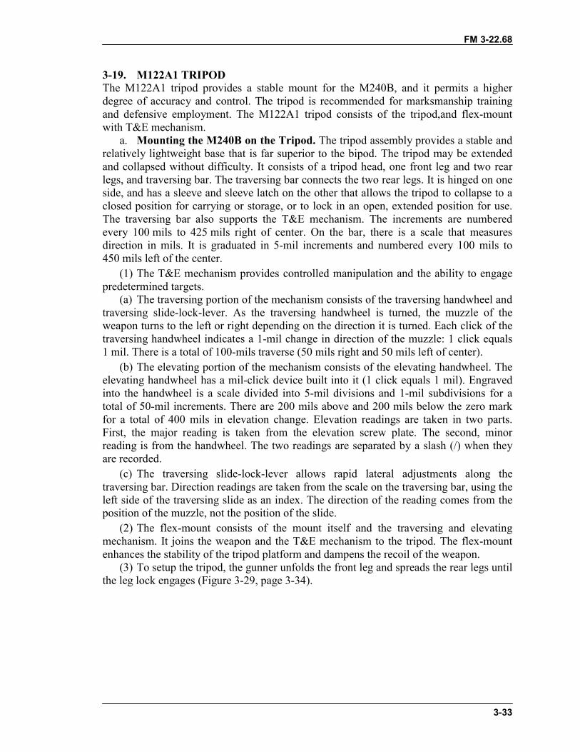
FM 3-22.68
3-33
3-19. M122A1 TRIPODThe M122A1 tripod provides a stable mount for the M240B, and it permits a higherdegree of accuracy and control. The tripod is recommended for marksmanship trainingand defensive employment. The M122A1 tripod consists of the tripod,and flex-mountwith T&E mechanism.
a. Mounting the M240B on the Tripod. The tripod assembly provides a stable andrelatively lightweight base that is far superior to the bipod. The tripod may be extendedand collapsed without difficulty. It consists of a tripod head, one front leg and two rearlegs, and traversing bar. The traversing bar connects the two rear legs. It is hinged on oneside, and has a sleeve and sleeve latch on the other that allows the tripod to collapse to aclosed position for carrying or storage, or to lock in an open, extended position for use.The traversing bar also supports the T&E mechanism. The increments are numberedevery 100 mils to 425 mils right of center. On the bar, there is a scale that measuresdirection in mils. It is graduated in 5-mil increments and numbered every 100 mils to450 mils left of the center.
(1) The T&E mechanism provides controlled manipulation and the ability to engagepredetermined targets.
(a) The traversing portion of the mechanism consists of the traversing handwheel andtraversing slide-lock-lever. As the traversing handwheel is turned, the muzzle of theweapon turns to the left or right depending on the direction it is turned. Each click of thetraversing handwheel indicates a 1-mil change in direction of the muzzle: 1 click equals1 mil. There is a total of 100-mils traverse (50 mils right and 50 mils left of center).
(b) The elevating portion of the mechanism consists of the elevating handwheel. Theelevating handwheel has a mil-click device built into it (1 click equals 1 mil). Engravedinto the handwheel is a scale divided into 5-mil divisions and 1-mil subdivisions for atotal of 50-mil increments. There are 200 mils above and 200 mils below the zero markfor a total of 400 mils in elevation change. Elevation readings are taken in two parts.First, the major reading is taken from the elevation screw plate. The second, minorreading is from the handwheel. The two readings are separated by a slash (/) when theyare recorded.
(c) The traversing slide-lock-lever allows rapid lateral adjustments along thetraversing bar. Direction readings are taken from the scale on the traversing bar, using theleft side of the traversing slide as an index. The direction of the reading comes from theposition of the muzzle, not the position of the slide.
(2) The flex-mount consists of the mount itself and the traversing and elevatingmechanism. It joins the weapon and the T&E mechanism to the tripod. The flex-mountenhances the stability of the tripod platform and dampens the recoil of the weapon.
(3) To setup the tripod, the gunner unfolds the front leg and spreads the rear legs untilthe leg lock engages (Figure 3-29, page 3-34).
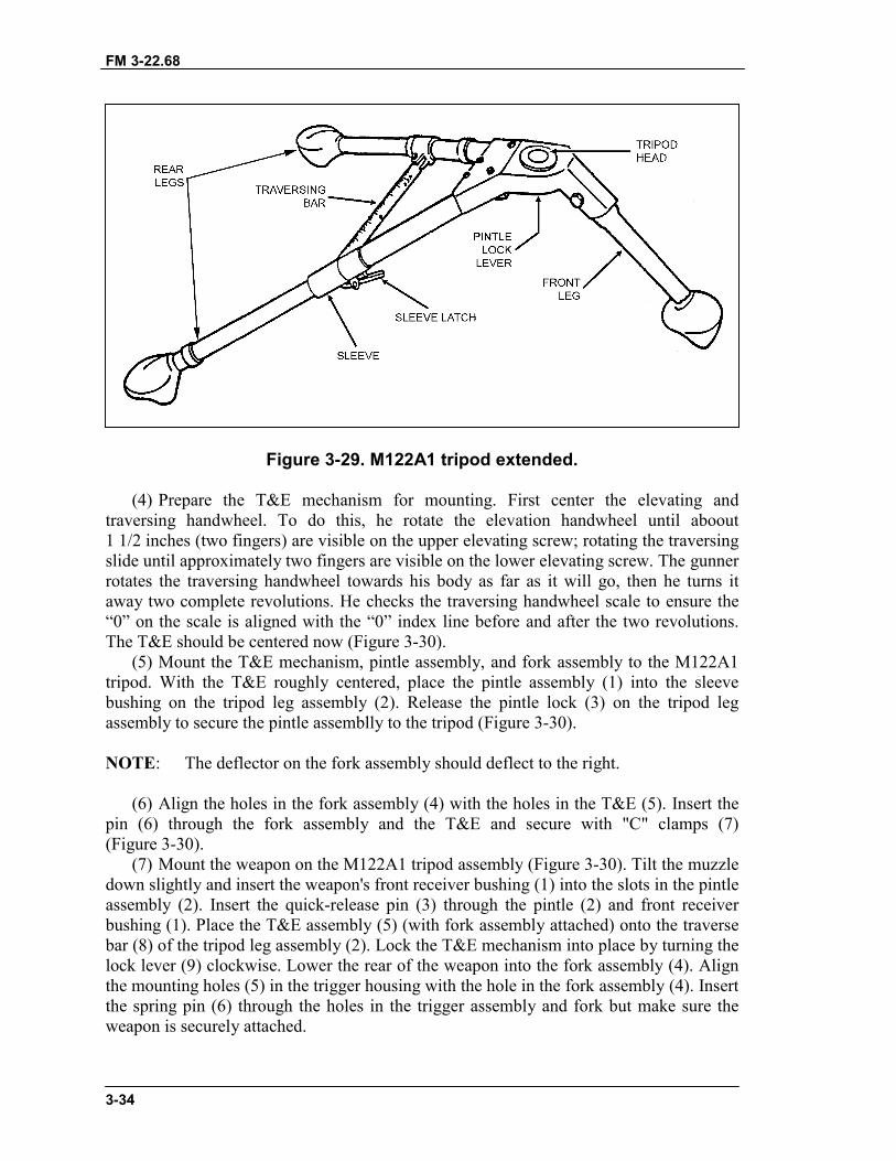
FM 3-22.68
3-34
Figure 3-29. M122A1 tripod extended.
(4) Prepare the T&E mechanism for mounting. First center the elevating andtraversing handwheel. To do this, he rotate the elevation handwheel until aboout1 1/2 inches (two fingers) are visible on the upper elevating screw; rotating the traversingslide until approximately two fingers are visible on the lower elevating screw. The gunnerrotates the traversing handwheel towards his body as far as it will go, then he turns itaway two complete revolutions. He checks the traversing handwheel scale to ensure the“0” on the scale is aligned with the “0” index line before and after the two revolutions.The T&E should be centered now (Figure 3-30).
(5) Mount the T&E mechanism, pintle assembly, and fork assembly to the M122A1tripod. With the T&E roughly centered, place the pintle assembly (1) into the sleevebushing on the tripod leg assembly (2). Release the pintle lock (3) on the tripod legassembly to secure the pintle assemblly to the tripod (Figure 3-30).
NOTE: The deflector on the fork assembly should deflect to the right.
(6) Align the holes in the fork assembly (4) with the holes in the T&E (5). Insert thepin (6) through the fork assembly and the T&E and secure with "C" clamps (7)(Figure 3-30).
(7) Mount the weapon on the M122A1 tripod assembly (Figure 3-30). Tilt the muzzledown slightly and insert the weapon's front receiver bushing (1) into the slots in the pintleassembly (2). Insert the quick-release pin (3) through the pintle (2) and front receiverbushing (1). Place the T&E assembly (5) (with fork assembly attached) onto the traversebar (8) of the tripod leg assembly (2). Lock the T&E mechanism into place by turning thelock lever (9) clockwise. Lower the rear of the weapon into the fork assembly (4). Alignthe mounting holes (5) in the trigger housing with the hole in the fork assembly (4). Insertthe spring pin (6) through the holes in the trigger assembly and fork but make sure theweapon is securely attached.
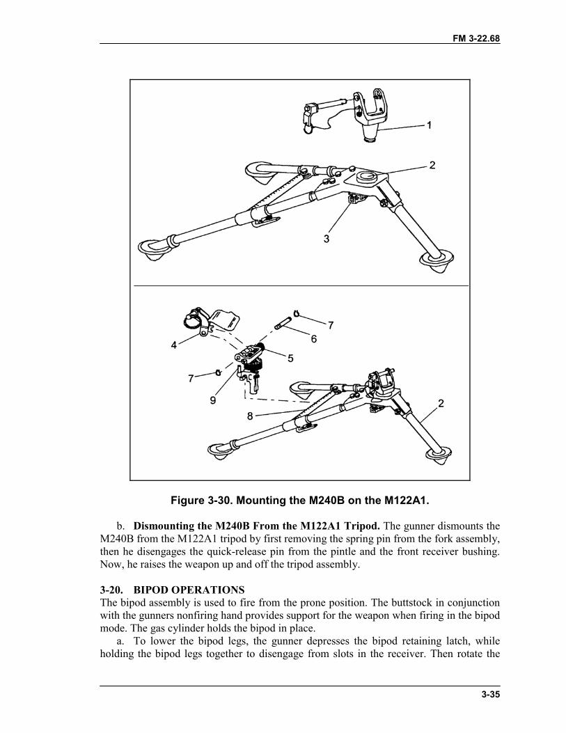
FM 3-22.68
3-35
Figure 3-30. Mounting the M240B on the M122A1.
b. Dismounting the M240B From the M122A1 Tripod. The gunner dismounts theM240B from the M122A1 tripod by first removing the spring pin from the fork assembly,then he disengages the quick-release pin from the pintle and the front receiver bushing.Now, he raises the weapon up and off the tripod assembly.
3-20. BIPOD OPERATIONSThe bipod assembly is used to fire from the prone position. The buttstock in conjunctionwith the gunners nonfiring hand provides support for the weapon when firing in the bipodmode. The gas cylinder holds the bipod in place.
a. To lower the bipod legs, the gunner depresses the bipod retaining latch, whileholding the bipod legs together to disengage from slots in the receiver. Then rotate the
FM 3-22.68
3-36
bipod legs down and release them so they lock in the vertical position. The bipod legs ofthe M240B do not extend (Figure 3-31).
b. To return the bipod to the locked upright position, the gunner holds the bipod legstogether to disengage them from the locked vertical position. Then he rotates the bipodlegs rearward, depressing the bipod retaining latch, and engage the bipod leg hooks intothe slots of the receiver. The bipod retaining latch will return to its original position,locking the bipod legs into position.
Figure 3-31. Lowering the bipod.
3-21. TRIPOD OPERATIONSThe M122A1 tripod provides a stable mount for the M240B, and it permits a high degreeof accuracy and control. The gunner unfolds the front leg and positions it toward thetarget and spreads the rear legs until the leg lock engages.
Section IV. PERFORMANCE PROBLEMS AND DESTRUCTIONThis section identifies some of the problems that cause the weapon to performimproperly. It also explains how to identify unserviceable parts, and how to destroy theM240B when authorized to do so.
3-22. MALFUNCTIONSA malfunction occurs when a mechanical failure causes the weapon to fire improperly.Defective ammunition or improper operation by the gunner is not considered amalfunction. Sluggish operation and uncontrolled fire are the most common malfunction.If cleaning and or lubricating the weapon does not fix the problem, then the gunner turnsit in to the unit armorer. Table 3-5 shows malfunctions, their probable causes, and thecorrective actions.
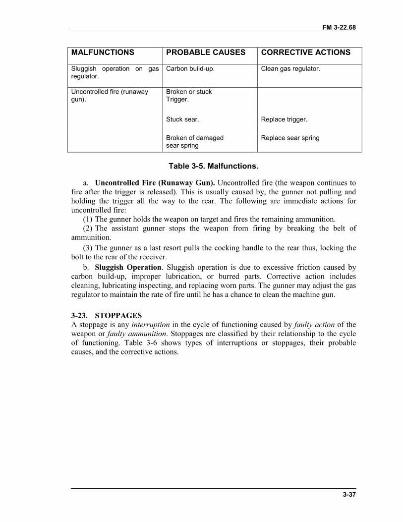
FM 3-22.68
3-37
MALFUNCTIONS PROBABLE CAUSES CORRECTIVE ACTIONS
Sluggish operation on gasregulator.
Carbon build-up. Clean gas regulator.
Broken or stuckTrigger.
Stuck sear. Replace trigger.
Uncontrolled fire (runawaygun).
Broken of damagedsear spring
Replace sear spring
Table 3-5. Malfunctions.
a. Uncontrolled Fire (Runaway Gun). Uncontrolled fire (the weapon continues tofire after the trigger is released). This is usually caused by, the gunner not pulling andholding the trigger all the way to the rear. The following are immediate actions foruncontrolled fire:
(1) The gunner holds the weapon on target and fires the remaining ammunition.(2) The assistant gunner stops the weapon from firing by breaking the belt of
ammunition.(3) The gunner as a last resort pulls the cocking handle to the rear thus, locking the
bolt to the rear of the receiver.b. Sluggish Operation. Sluggish operation is due to excessive friction caused by
carbon build-up, improper lubrication, or burred parts. Corrective action includescleaning, lubricating inspecting, and replacing worn parts. The gunner may adjust the gasregulator to maintain the rate of fire until he has a chance to clean the machine gun.
3-23. STOPPAGESA stoppage is any interruption in the cycle of functioning caused by faulty action of theweapon or faulty ammunition. Stoppages are classified by their relationship to the cycleof functioning. Table 3-6 shows types of interruptions or stoppages, their probablecauses, and the corrective actions.
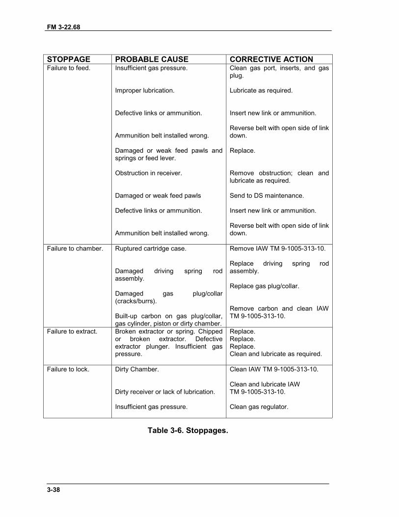
FM 3-22.68
3-38
STOPPAGE PROBABLE CAUSE CORRECTIVE ACTIONFailure to feed. Insufficient gas pressure.
Improper lubrication.
Defective links or ammunition.
Ammunition belt installed wrong.
Damaged or weak feed pawls andsprings or feed lever.
Obstruction in receiver.
Damaged or weak feed pawls
Defective links or ammunition.
Ammunition belt installed wrong.
Clean gas port, inserts, and gasplug.
Lubricate as required.
Insert new link or ammunition.
Reverse belt with open side of linkdown.
Replace.
Remove obstruction; clean andlubricate as required.
Send to DS maintenance.
Insert new link or ammunition.
Reverse belt with open side of linkdown.
Failure to chamber. Ruptured cartridge case.
Damaged driving spring rodassembly.
Damaged gas plug/collar(cracks/burrs).
Built-up carbon on gas plug/collar,gas cylinder, piston or dirty chamber.
Remove IAW TM 9-1005-313-10.
Replace driving spring rodassembly.
Replace gas plug/collar.
Remove carbon and clean IAWTM 9-1005-313-10.
Failure to extract. Broken extractor or spring. Chippedor broken extractor. Defectiveextractor plunger. Insufficient gaspressure.
Replace.Replace.Replace.Clean and lubricate as required.
Failure to lock. Dirty Chamber.
Dirty receiver or lack of lubrication.
Insufficient gas pressure.
Clean IAW TM 9-1005-313-10.
Clean and lubricate IAWTM 9-1005-313-10.
Clean gas regulator.
Table 3-6. Stoppages.
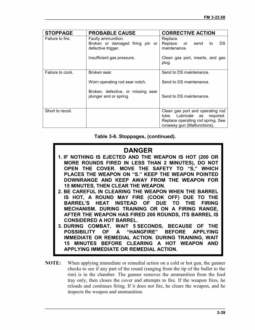
FM 3-22.68
3-39
STOPPAGE PROBABLE CAUSE CORRECTIVE ACTIONFailure to fire. Faulty ammunition.
Broken or damaged firing pin ordefective trigger.
Insufficient gas pressure.
Replace.Replace or send to DSmaintenance.
Clean gas port, inserts, and gasplug.
Failure to cock. Broken sear.
Worn operating rod sear notch.
Broken, defective, or missing searplunger and or spring.
Send to DS maintenance.
Send to DS maintenance.
Send to DS maintenance.
Short to recoil. Clean gas port and operating rodtube. Lubricate as required.Replace operating rod spring. Seerunaway gun (Malfunctions).
Table 3-6. Stoppages, (continued).
NOTE: When applying immediate or remedial action on a cold or hot gun, the gunnerchecks to see if any part of the round (ranging from the tip of the bullet to therim) is in the chamber. The gunner removes the ammunition from the feedtray only, then closes the cover and attempts to fire. If the weapon fires, hereloads and continues firing. If it does not fire, he clears the weapon, and heinspects the weapon and ammunition.
DANGER1. IF NOTHING IS EJECTED AND THE WEAPON IS HOT (200 OR
MORE ROUNDS FIRED IN LESS THAN 2 MINUTES), DO NOTOPEN THE COVER. MOVE THE SAFETY TO “S,” WHICHPLACES THE WEAPON ON “S.” KEEP THE WEAPON POINTEDDOWNRANGE AND KEEP AWAY FROM THE WEAPON FOR15 MINUTES, THEN CLEAR THE WEAPON.
2. BE CAREFUL IN CLEARING THE WEAPON WHEN THE BARRELIS HOT, A ROUND MAY FIRE (COOK OFF) DUE TO THEBARREL’S HEAT INSTEAD OF DUE TO THE FIRINGMECHANISM. DURING TRAINING OR ON A FIRING RANGE,AFTER THE WEAPON HAS FIRED 200 ROUNDS, ITS BARREL ISCONSIDERED A HOT BARREL.
3. DURING COMBAT, WAIT 5 SECONDS, BECAUSE OF THEPOSSIBILITY OF A “HANGFIRE” BEFORE APPLYINGIMMEDIATE OR REMEDIAL ACTION. DURING TRAINING, WAIT15 MINUTES BEFORE CLEARING A HOT WEAPON ANDAPPLYING IMMEDIATE OR REMEDIAL ACTION.
FM 3-22.68
3-40
3-24. IMMEDIATE ACTIONImmediate action is action taken to reduce a stoppage without looking for the cause.Immediate action should be taken in the event of either a misfire or a cook off. A misfireis the failure of a chambered round to fire. Such failure can be due to an ammunitiondefect or faulty firing mechanism. A cook off is the firing of a round by the heat of a hotbarrel and not by the firing mechanism. Cookoffs can be avoided by applying immediateaction within 10 seconds after a failure to fire. If the M240B stops firing, the gunnerperforms the following immediate actions are taken. (An effective memory aid is POPP,which stands for pull, observe, push, and press.)
a. Pulls and locks the cocking handle to the rear while observing the ejection port tosee if a cartridge case, belt link, or round is ejected. Ensures that the bolt remains to therear to prevent double feeding if a round or cartridge case is not ejected.
b. If a cartridge case, belt link, or a round is ejected, returns cocking handle toforward position, aim on the target, and presses the trigger. If the weapon still does notfire, takes remedial action. If a cartridge case, belt link, or round is not ejected, takesremedial action.
3-25. REMEDIAL ACTIONRemedial action is any action taken to determine the cause of a stoppage and to restorethe weapon to an operational condition. This action is taken only after immediate actiondid not remedy the problem.
a. Cold Weapon Procedures. When a stoppage occurs with a cold weapon andimmediate action has failed, the gunner uses the following procedures.
(1) Pulls the cocking handle to the rear, locking the bolt. Returns the cocking handleand places the safety to SAFE.
(2) Places the weapon on the ground or away from his face and opens the cover,performs the four-point safety check. Reloads and continues to fire.
(3) If the weapon does not fire, clears the weapon and inspects it and the ammunition.b. Hot Weapon Procedures. If the stoppage occurs with a hot weapon (200 rounds
or more in 2 minutes or as noted above for training), the gunner moves the safety toSAFE, waits 5 seconds (during training, lets the weapon cool for 15 minutes), uses thesame procedures as outlined for cold weapon procedures.
c. Jammed Cocking Handle. If a stoppage occurs and the cocking handle cannot bepulled to the rear by hand (the bolt may be fully forward and locked or only partiallyforward), the gunner takes the following steps.
(1) Tries once again to pull the cocking handle by hand.
(2) If the weapon is hot enough to cause a cook off, moves all soldiers a safe distancefrom the weapon and keeps them away for 15 minutes.
(3) After the gun has cooled, the gunner will pull the cocking handle to the rear.Ensures rearward pressure is kept on the cocking handle until the driving spring rod
WARNINGDo not try to force the cocking handle to the rear with yourfoot or a heavy object. This could damage the weapon.
FM 3-22.68
3-41
assembly is removed. Opens the cover and disassembles the gun. (The assistant gunnerhelps the gunner do this.)
(4) Removes the round or fired cartridge. Uses cleaning rod or ruptured cartridgeextractor if necessary.
(a) In a training situation, after completing the remedial action procedures, the gunshould not be fired until an inspection by an ordnance specialist has been made.
(b) In a combat situation, after the stoppage has been corrected, the gunner changesthe barrel and tries to fire. If the weapon fails to function properly, the gunner sends it tothe unit armorer.
3-26. STUCK BARRELStuck barrel is the result of the machine gun crew not properly cleaning the gas cylinderand gas regulator plug. During training or range firing the M240B should be cleared,disassemble and cleaned immediately. In combat, the M240B should be cleaned as soonas possible. The gun crew performs the following actions, only if the weapon can not beproperly cleaned at that time.
a. Pulls the cocking handle to the rear, locking the bolt. Returns the cocking handleand places the safety to SAFE.
b. Places the weapon on the ground or away from his face and opens the cover,performs the four-point safety check.
c. The gunner ensures that the barrel is still locked to the receiver with the carryinghandle to the right.
d. The assistant gunner places the heat protective mitten on his right hand. With themitten on he will remove the gas regulator collar from the barrel that is secured to thereceiver.
e. With the gas regulator collar removed, the gunner and assistant gunner removethe barrel as outlined in Section II.
f. After removal of the barrel, the assistant gunner will remove the gas regulatorcollar and gas regulator plug from the spare barrel.
g With these removed the gunner and assistant gunner inserts the barrel into thesocket of the receiver ensuring that the gas regulator plug is going into the gas holebushing. Once the barrel is secured to the receiver the assistant gunner secures the gasregulator collar on the gas regulator plug.
h. The gunner, after ensuring the barrel is secured to the receiver (2 to 7 clicks) andthe collar is secure, will reload and continue firing.
3-27. DESTRUCTION PROCEDURESDestruction of any military weapon is only authorized as a last resort to prevent enemycapture or use. This paragraph discusses the field-expedient means of this destruction; itdoes not replace published policies. In combat situations, the commander has theauthority to destroy weapons, but he must report this destruction through channels.
a. Disassemble the weapon as completely as time permits. Use the barrel or tripodmount to destroy the bolt and operating rod assembly, barrels, rear and front sights, andmounts.
b. Bury the disassembled weapon or dump the parts into a stream, a sump, or alatrine.

FM 3-22.68
3-42
c. Burn the weapon by placing an incendiary grenade on the receiver group over thebolt (with the cover resting on the grenade) and detonating the grenade.
d. Smash the traversing and elevating mechanism and pintle assembly. Bend thetripod legs.
FM 3-22.68
4-1
CHAPTER 4MACHINE GUN MARKSMANSHIP TRAINING
This chapter aids trainers in preparing and conducting machine gunmarksmanship training for the machine gun. Machine gun marksmanshiptraining is conducted in three phases: preliminary gunnery, basic gunnery,and advanced gunnery in Chapter 5.
Section I. INTRODUCTIONMarksmanship begins with nonfiring individual skill proficiency and concludes withcollective proficiency firing under demanding conditions.
4-1. OBJECTIVESThe objectives of machine gun marksmanship training are to produce gunners that arethoroughly capable of the following:
a. Accurate Initial Burst. Obtaining an accurate initial burst of fire on the target isessential to good marksmanship. This requires the gunner to estimate range to the target,set the sights, and apply the fundamentals of marksmanship while engaging targets.
b. Adjustment of Fire. The gunner must observe the strike of the rounds when theinitial burst is fired. If not on target, he manipulates the T&E mechanism until the roundsdo strike the target. The assistant gunner must be proficient in observing the strike ofrounds and in observing and using tracers so the gunner can rapidly relay the machinegun on the target for engagement.
c. Speed. Speed is also essential to good marksmanship; it is attained by practice inboth dry-fire and live-fire exercises. It is an acquired skill gained through extensivetraining that combines other skills when delivering fire. Speed should not be stressed tothe detriment of accuracy.
4-2. TRAINING PHASESMarksmanship training for the machine gun is progressive in nature. It begins withnonfiring individual skill proficiency and concludes with collective proficiency firingunder demanding conditions. Gunners and leaders must master the fundamentals beforeattempting individual and collective firings. More effective and efficient marksmanshipoccurs if live firing is preceded with good preliminary marksmanship training. Likewise,proficient individual firing will achieve more proficient collective firing.
a. Preliminary Gunnery. In this phase, the gunner learns and demonstratesproficiency on individual skills that prepare him to fire live ammunition. This includesmastering mechanical training, the four fundamentals of marksmanship, T&Emanipulation, sight adjustments, crew drill, and fire commands.
b. Basic Gunnery. In this phase, the gunner applies the fundamentals in live-fireexercises during day and night conditions. This includes zeroing, 10-meter firing withcrew drill, field zeroing, and transition firing with crew drill.
c. Advanced Gunnery. In this phase, gunners are trained on combat techniques offire, techniques of employment, and live-fire exercise during NBC conditions.
FM 3-22.68
4-2
4-3. TRAINING STRATEGYTraining strategy involves the overall concept for integrating resources into a programthat trains individual and collective skills needed to perform a wartime mission. The goalof a marksmanship program is to produce well-trained gunners who can win and surviveon the battlefield.
a. Leaders implement training strategies for machine gun marksmanship inTRADOC institutions (IET, NCOES, IOBC, and IOAC) and in units. The overall trainingstrategy is multifaceted and is inclusive of the specific strategies used in institution andunit programs. Also included are the supporting strategies that use resources such aspublications, ranges, ammunition, training aids, devices, simulators, and simulations.These strategies focus on developing critical soldier skills and leader skills that arerequired for the intended outcome.
b. The training strategies contain two components: initial training and sustainmenttraining. Both may include individual and collective skills. Initial training is criticalbecause a task that is taught correctly and learned well is retained longer. When aninterim of nonuse occurs, well-trained skills are more quickly regained and sustained.The more difficult and complex the task, the harder it is to sustain the skill. Personnelturnover plays a major factor in the decay of collective skills, since the loss of criticalteam members requires retraining to regain proficiency. Retraining becomes necessarywhen a long period elapses between initial and sustainment training sessions or when thetraining doctrine is altered.
c. The training strategy for machine gun marksmanship begins in the institutions andcontinues in the unit. Figure 4-1, illustrates an example of this overall process, whichprovides a concept of the flow of unit sustainment training. Combat arms IET providesfield units with soldiers who are familiar with standards in basic marksmanship tasks.The soldiers graduating from these courses have been trained to maintain their machineguns and to hit a variety of targets. They have learned range determination, targetdetection, application of marksmanship fundamentals, and other skills needed to engage atarget.
d. Additional skills trained in the institution include techniques for employment,classes of fire, and fire commands. These skills must then be reinforced in the unit.Related soldier skills of camouflage, cover and concealment, maneuver, and preparationand selection of a fighting position are addressed in STP 21-24-SMCT, which must beintegrated into tactical training.
e. Training continues in units on the basic skills taught in combat arms IET.Additional skills, such as suppressive fire and supporting fire, are trained and thenintegrated into collective training exercises, which include squad and platoon live-fireexercises. (A unit machine gun marksmanship training program is explained inAppendix B.) The strategy for sustaining the basic marksmanship skills that is taught incombat arms IET involves periodic preliminary gunnery, followed by 10-meter, transitionfiring, and qualification range firing. However, a unit must establish a year-roundprogram to sustain skills. Key elements include training the trainers and refresher trainingof nonfiring skills.
f. In the unit, individual proficiency and leader proficiency of marksmanship tasksare integrated into collective training that includes squad, section, and platoon drills andSTXs. The collective tasks in these exercises, and how they are planned and conducted,
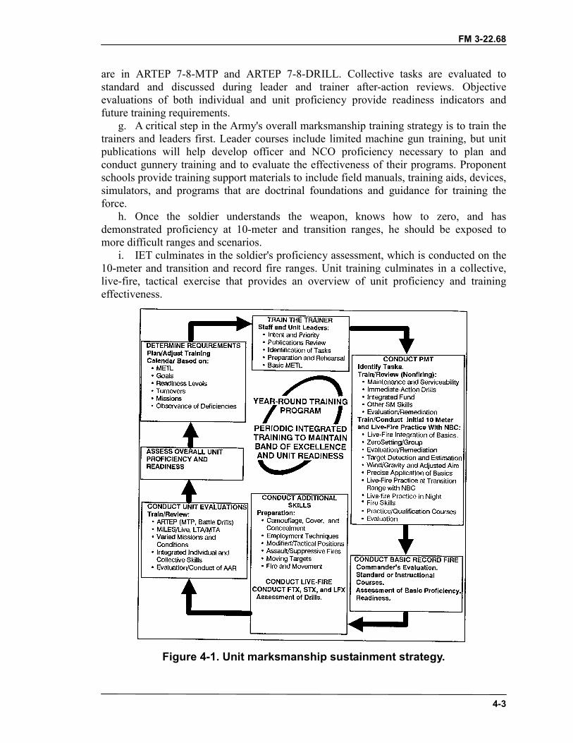
FM 3-22.68
4-3
are in ARTEP 7-8-MTP and ARTEP 7-8-DRILL. Collective tasks are evaluated tostandard and discussed during leader and trainer after-action reviews. Objectiveevaluations of both individual and unit proficiency provide readiness indicators andfuture training requirements.
g. A critical step in the Army's overall marksmanship training strategy is to train thetrainers and leaders first. Leader courses include limited machine gun training, but unitpublications will help develop officer and NCO proficiency necessary to plan andconduct gunnery training and to evaluate the effectiveness of their programs. Proponentschools provide training support materials to include field manuals, training aids, devices,simulators, and programs that are doctrinal foundations and guidance for training theforce.
h. Once the soldier understands the weapon, knows how to zero, and hasdemonstrated proficiency at 10-meter and transition ranges, he should be exposed tomore difficult ranges and scenarios.
i. IET culminates in the soldier's proficiency assessment, which is conducted on the10-meter and transition and record fire ranges. Unit training culminates in a collective,live-fire, tactical exercise that provides an overview of unit proficiency and trainingeffectiveness.
Figure 4-1. Unit marksmanship sustainment strategy.
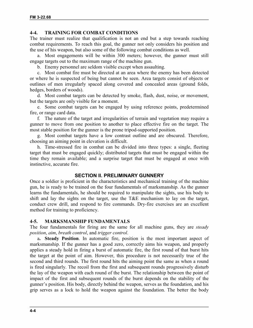
FM 3-22.68
4-4
4-4. TRAINING FOR COMBAT CONDITIONSThe trainer must realize that qualification is not an end but a step towards reachingcombat requirements. To reach this goal, the gunner not only considers his position andthe use of his weapon, but also some of the following combat conditions as well.
a. Most engagements will be within 300 meters; however, the gunner must stillengage targets out to the maximum range of the machine gun.
b. Enemy personnel are seldom visible except when assaulting.c. Most combat fire must be directed at an area where the enemy has been detected
or where he is suspected of being but cannot be seen. Area targets consist of objects oroutlines of men irregularly spaced along covered and concealed areas (ground folds,hedges, borders of woods).
d. Most combat targets can be detected by smoke, flash, dust, noise, or movement,but the targets are only visible for a moment.
e. Some combat targets can be engaged by using reference points, predeterminedfire, or range card data.
f. The nature of the target and irregularities of terrain and vegetation may require agunner to move from one position to another to place effective fire on the target. Themost stable position for the gunner is the prone tripod-supported position.
g. Most combat targets have a low contrast outline and are obscured. Therefore,choosing an aiming point in elevation is difficult.
h. Time-stressed fire in combat can be divided into three types: a single, fleetingtarget that must be engaged quickly; distributed targets that must be engaged within thetime they remain available; and a surprise target that must be engaged at once withinstinctive, accurate fire.
SECTION II. PRELIMINARY GUNNERYOnce a soldier is proficient in the characteristics and mechanical training of the machinegun, he is ready to be trained on the four fundamentals of marksmanship. As the gunnerlearns the fundamentals, he should be required to manipulate the sights, use his body toshift and lay the sights on the target, use the T&E mechanism to lay on the target,conduct crew drill, and respond to fire commands. Dry-fire exercises are an excellentmethod for training to proficiency.
4-5. MARKSMANSHIP FUNDAMENTALSThe four fundamentals for firing are the same for all machine guns, they are steadyposition, aim, breath control, and trigger control.
a. Steady Position. In automatic fire, position is the most important aspect ofmarksmanship. If the gunner has a good zero, correctly aims his weapon, and properlyapplies a steady hold in firing a burst of automatic fire, the first round of that burst hitsthe target at the point of aim. However, this procedure is not necessarily true of thesecond and third rounds. The first round hits the aiming point the same as when a roundis fired singularly. The recoil from the first and subsequent rounds progressively disturbthe lay of the weapon with each round of the burst. The relationship between the point ofimpact of the first and subsequent rounds of the burst depends on the stability of thegunner’s position. His body, directly behind the weapon, serves as the foundation, and hisgrip serves as a lock to hold the weapon against the foundation. The better the body
FM 3-22.68
4-5
alignment and the steadier the grip, the less dispersed the rounds of a burst of automaticfire will be.
b. Aim. To aim the machine gun, the gunner must align the sights, focus his eye,obtain a correct sight picture, control his breathing, and maintain trigger control.
(1) Sight Alignment. To obtain correct align, the gunner centers the front sight post inthe aperture of the rear sight. For a correct sight picture, the gunner centers the target overthe front sight post so that it appears to rest lightly on top of the sight. The aspects ofobtaining an accurate initial burst through sight alignment and sight picture, triggermanipulation, and zeroing are the same for tripod training as for bipod training
(2) Focus of the Eye. A good firing position places the eye directly on line with thecenter of the rear sight. The gunner must focus on the tip of the front sight post. Thenatural ability of the eye to center objects in the rear sight and to seek the point ofgreatest light aids in providing correct sight alignment.
(3) Sight Picture. A correct sight picture has the target, front sight post, and rear sightaligned. The sight picture consists of sight alignment and placement of the aiming pointon the target. The gunner aligns the front sight post in the center of the rear sight and thenaligns the sights with the target. The top of the front sight post is aligned on the centerbase of the target (Figure 4-2).
Figure 4-2. Sight picture.
c. Breath Control. When firing in bipod-mounted mode, two types of breathcontrol are used. When firing single shots, as in zeroing, the gunner stops breathing aftermost of the air has been exhaled during the normal breathing cycle. He fires before hefeels any discomfort. During automatic fire, ideally, the gunner exhales and stops hisbreath when pressing the trigger. He does not have time to take deep breaths betweenbursts. He must hold his breath before each burst or adapt his breathing by taking quickshallow breaths or taking deeper breaths between several bursts.
d. Trigger Control. Pressing the trigger straight to the rear and releasing it helpscontrol the number of rounds in each burst and prevents disturbing the lay of the weapon.For this the gunner must learn how to manipulate the trigger so, that he may get thedesired burst he wishes to obtain.
4-6. FIRING POSITIONSThe bipod-supported prone and fighting positions and the tripod-supported prone andfighting positions are covered in preliminary gunnery.
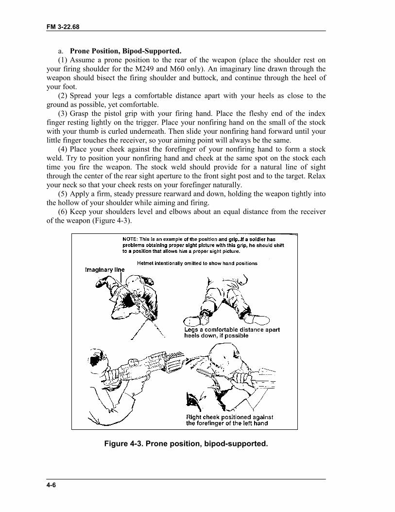
FM 3-22.68
4-6
a. Prone Position, Bipod-Supported.(1) Assume a prone position to the rear of the weapon (place the shoulder rest on
your firing shoulder for the M249 and M60 only). An imaginary line drawn through theweapon should bisect the firing shoulder and buttock, and continue through the heel ofyour foot.
(2) Spread your legs a comfortable distance apart with your heels as close to theground as possible, yet comfortable.
(3) Grasp the pistol grip with your firing hand. Place the fleshy end of the indexfinger resting lightly on the trigger. Place your nonfiring hand on the small of the stockwith your thumb is curled underneath. Then slide your nonfiring hand forward until yourlittle finger touches the receiver, so your aiming point will always be the same.
(4) Place your cheek against the forefinger of your nonfiring hand to form a stockweld. Try to position your nonfiring hand and cheek at the same spot on the stock eachtime you fire the weapon. The stock weld should provide for a natural line of sightthrough the center of the rear sight aperture to the front sight post and to the target. Relaxyour neck so that your cheek rests on your forefinger naturally.
(5) Apply a firm, steady pressure rearward and down, holding the weapon tightly intothe hollow of your shoulder while aiming and firing.
(6) Keep your shoulders level and elbows about an equal distance from the receiverof the weapon (Figure 4-3).
Figure 4-3. Prone position, bipod-supported.
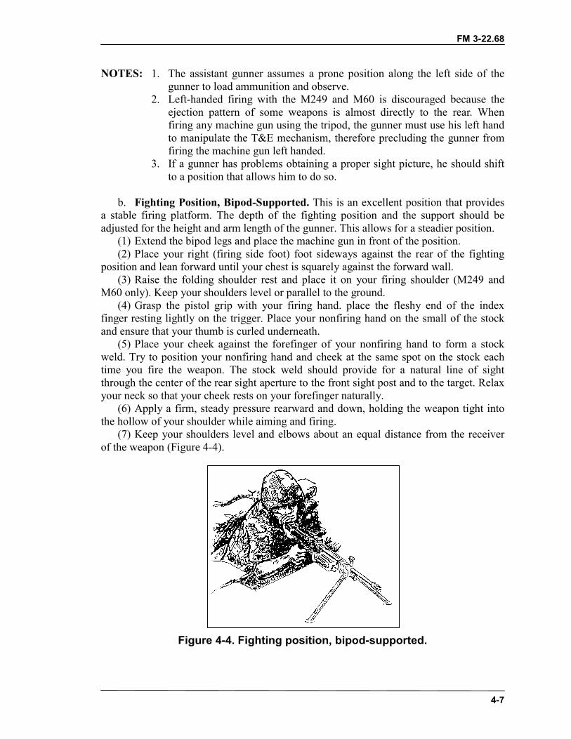
FM 3-22.68
4-7
NOTES: 1. The assistant gunner assumes a prone position along the left side of thegunner to load ammunition and observe.
2. Left-handed firing with the M249 and M60 is discouraged because theejection pattern of some weapons is almost directly to the rear. Whenfiring any machine gun using the tripod, the gunner must use his left handto manipulate the T&E mechanism, therefore precluding the gunner fromfiring the machine gun left handed.
3. If a gunner has problems obtaining a proper sight picture, he should shiftto a position that allows him to do so.
b. Fighting Position, Bipod-Supported. This is an excellent position that providesa stable firing platform. The depth of the fighting position and the support should beadjusted for the height and arm length of the gunner. This allows for a steadier position.
(1) Extend the bipod legs and place the machine gun in front of the position.(2) Place your right (firing side foot) foot sideways against the rear of the fighting
position and lean forward until your chest is squarely against the forward wall.(3) Raise the folding shoulder rest and place it on your firing shoulder (M249 and
M60 only). Keep your shoulders level or parallel to the ground.(4) Grasp the pistol grip with your firing hand. place the fleshy end of the index
finger resting lightly on the trigger. Place your nonfiring hand on the small of the stockand ensure that your thumb is curled underneath.
(5) Place your cheek against the forefinger of your nonfiring hand to form a stockweld. Try to position your nonfiring hand and cheek at the same spot on the stock eachtime you fire the weapon. The stock weld should provide for a natural line of sightthrough the center of the rear sight aperture to the front sight post and to the target. Relaxyour neck so that your cheek rests on your forefinger naturally.
(6) Apply a firm, steady pressure rearward and down, holding the weapon tight intothe hollow of your shoulder while aiming and firing.
(7) Keep your shoulders level and elbows about an equal distance from the receiverof the weapon (Figure 4-4).
Figure 4-4. Fighting position, bipod-supported.
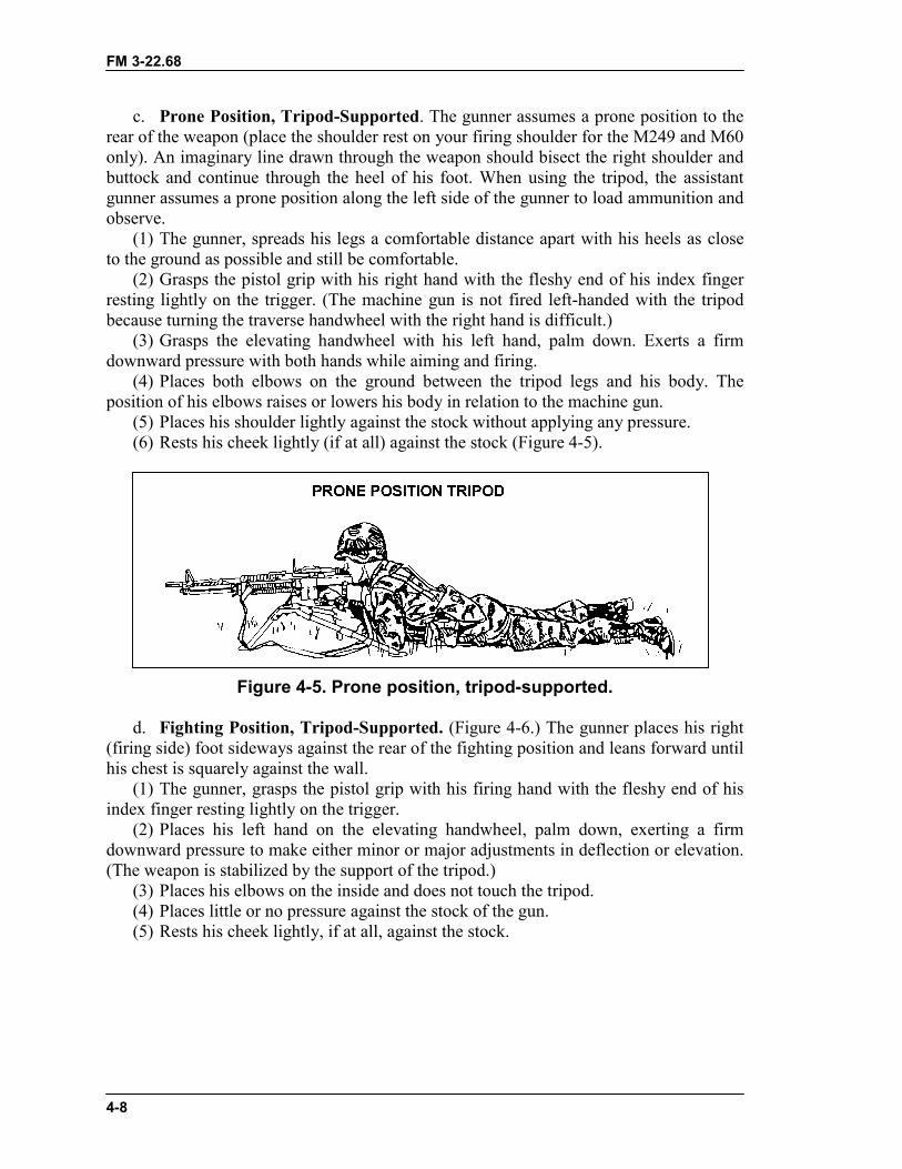
FM 3-22.68
4-8
c. Prone Position, Tripod-Supported. The gunner assumes a prone position to therear of the weapon (place the shoulder rest on your firing shoulder for the M249 and M60only). An imaginary line drawn through the weapon should bisect the right shoulder andbuttock and continue through the heel of his foot. When using the tripod, the assistantgunner assumes a prone position along the left side of the gunner to load ammunition andobserve.
(1) The gunner, spreads his legs a comfortable distance apart with his heels as closeto the ground as possible and still be comfortable.
(2) Grasps the pistol grip with his right hand with the fleshy end of his index fingerresting lightly on the trigger. (The machine gun is not fired left-handed with the tripodbecause turning the traverse handwheel with the right hand is difficult.)
(3) Grasps the elevating handwheel with his left hand, palm down. Exerts a firmdownward pressure with both hands while aiming and firing.
(4) Places both elbows on the ground between the tripod legs and his body. Theposition of his elbows raises or lowers his body in relation to the machine gun.
(5) Places his shoulder lightly against the stock without applying any pressure.(6) Rests his cheek lightly (if at all) against the stock (Figure 4-5).
Figure 4-5. Prone position, tripod-supported.
d. Fighting Position, Tripod-Supported. (Figure 4-6.) The gunner places his right(firing side) foot sideways against the rear of the fighting position and leans forward untilhis chest is squarely against the wall.
(1) The gunner, grasps the pistol grip with his firing hand with the fleshy end of hisindex finger resting lightly on the trigger.
(2) Places his left hand on the elevating handwheel, palm down, exerting a firmdownward pressure to make either minor or major adjustments in deflection or elevation.(The weapon is stabilized by the support of the tripod.)
(3) Places his elbows on the inside and does not touch the tripod.(4) Places little or no pressure against the stock of the gun.(5) Rests his cheek lightly, if at all, against the stock.
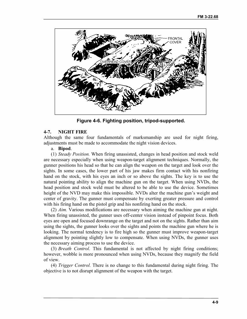
FM 3-22.68
4-9
Figure 4-6. Fighting position, tripod-supported.
4-7. NIGHT FIREAlthough the same four fundamentals of marksmanship are used for night firing,adjustments must be made to accommodate the night vision devices.
a. Bipod.(1) Steady Position. When firing unassisted, changes in head position and stock weld
are necessary especially when using weapon-target alignment techniques. Normally, thegunner positions his head so that he can align the weapon on the target and look over thesights. In some cases, the lower part of his jaw makes firm contact with his nonfiringhand on the stock, with his eyes an inch or so above the sights. The key is to use thenatural pointing ability to align the machine gun on the target. When using NVDs, thehead position and stock weld must be altered to be able to use the device. Sometimesheight of the NVD may make this impossible. NVDs alter the machine gun’s weight andcenter of gravity. The gunner must compensate by exerting greater pressure and controlwith his firing hand on the pistol grip and his nonfiring hand on the stock.
(2) Aim. Various modifications are necessary when aiming the machine gun at night.When firing unassisted, the gunner uses off-center vision instead of pinpoint focus. Botheyes are open and focused downrange on the target and not on the sights. Rather than aimusing the sights, the gunner looks over the sights and points the machine gun where he islooking. The normal tendency is to fire high so the gunner must improve weapon-targetalignment by pointing slightly low to compensate. When using NVDs, the gunner usesthe necessary aiming process to use the device.
(3) Breath Control. This fundamental is not affected by night firing conditions;however, wobble is more pronounced when using NVDs, because they magnify the fieldof view.
(4) Trigger Control. There is no change to this fundamental during night firing. Theobjective is to not disrupt alignment of the weapon with the target.
FM 3-22.68
4-10
b. Tripod.(1) Steady Position. When firing at predetermined targets with the weapon laid on
each target, there are not differences in steady position at night as compared to day.However, firing at night at targets of opportunity requires modifications. The gunner isrequired to use weapon-target alignment techniques. He must align the weapon on thetarget and look over the sights. His head is higher and his lower jaw is lightly on thestock if at all. With night vision devices, the gunner must position his head so that hisfiring eye is in line with the device.
(2) Aim. For targets of opportunity, the gunner uses the same techniques as with abipod during night firing except weapon-target alignment is achieved with the T&Emechanism.
(3) Breath Control. There are no changes in this fundamental.(4) Trigger Control. There are no changes in this fundamental.
4-8. NUCLEAR, BIOLOGICAL, CHEMICAL FIREThe four fundamentals remain valid in an NBC environment, although somemodifications may be needed to accommodate the equipment.
a. Bipod(1) Steady Position. The bulk of overgarments may require adjustments to the
position for stability and comfort. A consistent stock weld is difficult to maintain becauseof the shape of the protective masks. The gunner has to hold his head in an awkwardposition to see through the sight. If necessary, he may cant the weapon to overcome thissituation. This procedure relieves the neck muscles and places the eye on line with thecenter of the rear sight.
(2) Aim. The gunner may have to rotate (cant) the machine gun to see through the rearsight aperture. He should rotate only enough to align the sights, and only if necessary.Ballistics cause rounds to impact low in the direction of the cant at long ranges. If cantingat targets beyond 175 meters, the gunner must adjust his point of aim. The best techniqueis to aim at center base of the target initially and then make adjustments based on thestrike of the rounds. Right-handed firers adjust point of aim to the right and high; left-handed firers to the left and high.
(3) Breath Control. Although breathing is somewhat restricted and more difficultwhile wearing the protective mask, the impact is negligible. Care must be taken, to avoidhyperventilating during burst fire. The amount of oxygen inhaled by taking quick shallowbreaths or deeper breaths between bursts is significantly reduced.
(4) Trigger Control. Trigger control is affected when the gunner wears gloves. Theeffect cannot be accurately predicted for each soldier; therefore, practice and trainingunder these conditions are required.
b. Tripod.(1) Steady Position. Modifications are similar to those in bipod firing. There are two
other points of importance. Manipulating the T&E with gloves on is more difficultbecause the feel of the handwheel differs. The gunner may not sense the same control aswithout gloves. Second, hearing is impaired. Together, reduced sense of touch andhearing impairment make T&E manipulations especially difficult. For these reasons,adjustments may be considerably slower.
FM 3-22.68
4-11
(2) Aim. Unlike the bipod, the tripod does not allow the machine gun to be canted.This requires the gunner to position his head behind the stock to use the sight. Skilledgunners who make adjustments to the T&E quickly can confirm their sight picture andthen look over the sights to observe the strike of the round while firing. This not onlyprovides relief for the neck muscles but aids in making adjustments.
(3) Breath Control. Some considerations apply in the same way as with of the bipod;however, the stable platform of the tripod negates movement associated with breathing.
(4) Trigger Control. Like the bipod, control is different because the trigger feelsdifferent. Training familiarizes the gunner with the changes he must make while wearinggloves.
4-9. ENGAGEMENT OF MOVING TARGETSThe fundamentals used to hit moving targets are the same as those needed to hitstationary targets. However, the procedures to engage moving targets vary as the angle,speed, and range of the target varies. Targets moving directly at the gunner are engagedthe same as a stationary target; there is no change in the application of the fundamentals.But fast-moving targets at varying ranges and angles do require changes in theapplication of steady position and aiming. (For aerial targets engagements, seeAppendix C.)
a. Leads. To hit a moving target, the machine gun must be aimed ahead of the targetfar enough to cause the bullet and target to arrive at the same time at the same point. Thisdistance is measured in target lengths. One target length as seen by the gunner is onelead. Leads are measured from the center of mass. Table 4-1 gives the amount of leadneeded to hit a target moving at right angles, to the gunner, and at speeds and rangesindicated. The gunner makes adjustments as conditions change. If target speed is7 1/2 mph, the amount of lead is half that shown on the table; at 30 mph, double thatshown. The angle at which the target moves also changes the lead. If the target is movingon an oblique angle, only half the lead is required. For a target moving directly at thegunner, the aiming point is below the center base of the target depending on range andslope of the ground. For a target moving directly away from a gunner, the aiming point isabove the center base of the target (Figure 4-7). Too much lead is better than too littlebecause the target moves into the beaten zone, and observation of the strike of the roundsis easier in relation to the target.
SPEED RANGE OF TARGET300 meters 500 meters 900 meters
15 mph 1/2 X Target length 1 X Target length 2 X Target lengths
Table 4-1. Vehicle lead table.
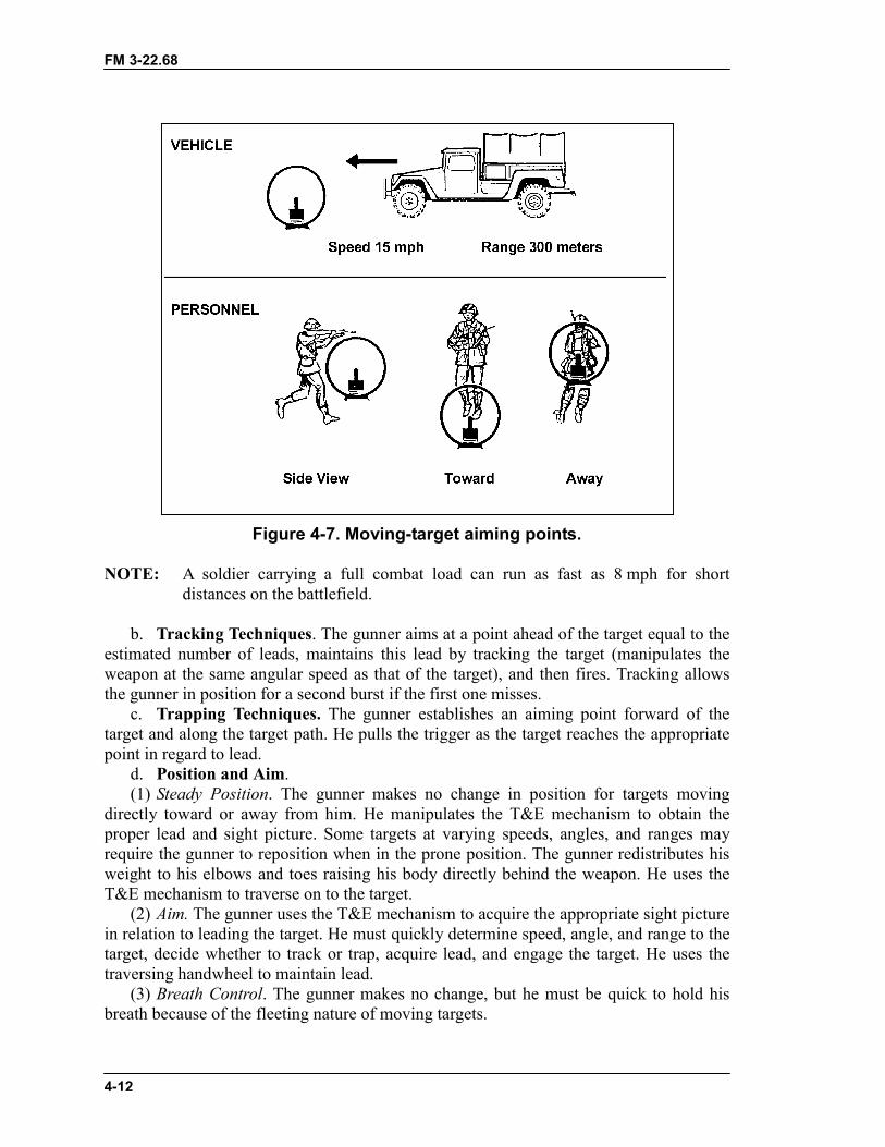
FM 3-22.68
4-12
Figure 4-7. Moving-target aiming points.
NOTE: A soldier carrying a full combat load can run as fast as 8 mph for shortdistances on the battlefield.
b. Tracking Techniques. The gunner aims at a point ahead of the target equal to theestimated number of leads, maintains this lead by tracking the target (manipulates theweapon at the same angular speed as that of the target), and then fires. Tracking allowsthe gunner in position for a second burst if the first one misses.
c. Trapping Techniques. The gunner establishes an aiming point forward of thetarget and along the target path. He pulls the trigger as the target reaches the appropriatepoint in regard to lead.
d. Position and Aim.(1) Steady Position. The gunner makes no change in position for targets moving
directly toward or away from him. He manipulates the T&E mechanism to obtain theproper lead and sight picture. Some targets at varying speeds, angles, and ranges mayrequire the gunner to reposition when in the prone position. The gunner redistributes hisweight to his elbows and toes raising his body directly behind the weapon. He uses theT&E mechanism to traverse on to the target.
(2) Aim. The gunner uses the T&E mechanism to acquire the appropriate sight picturein relation to leading the target. He must quickly determine speed, angle, and range to thetarget, decide whether to track or trap, acquire lead, and engage the target. He uses thetraversing handwheel to maintain lead.
(3) Breath Control. The gunner makes no change, but he must be quick to hold hisbreath because of the fleeting nature of moving targets.
FM 3-22.68
4-13
(4) Trigger Control. The gunner makes no change in applying this fundamental.e. Bipod Techniques. For targets moving to or from a gunner using a bipod, the
same procedures are used. From a prone position, the gunner may be required to adjusthis position quickly depending on range, angle, and speed of the target.
(1) Steady Position. If appropriate lead cannot be achieved by shifting his shouldersright or left (traverse) or by moving his elbows closer or farther a part (search), thegunner redistributes his weight to his elbows and toes and raises his body off the ground.Using his toes, the gunner shifts his body right or left in the opposite direction of thetarget and pivots on his elbows until the aiming point is well ahead of the target. Thegunner rapidly assumes a steady position, obtains the sight picture, leads and engages thetarget. Trapping is the preferred technique. In order to apply this method, the bipod legsmust move freely. When firing from a fighting position, the gunner must be flexibleenough to track any target in his sector. If lead cannot be achieved, he slides the bipodlegs in the appropriate direction (left or right) ahead of the target and continues as in theprone position. Trapping is still the preferred technique. If the terrain does not permitsliding the weapon left or right, the gunner lifts the bipod legs off the ground and placesthem where he can aim ahead of the target, reestablishes a steady position, and continuesas before.
(2) Aim. The gunner determines angle, speed, and range quickly; acquires theappropriate lead; and engages the target. He aligns the front sight post in the properposition to lead the target. For targets moving directly away, he places the front sight postabove center of mass. For targets moving directly at him, he aligns the front sight postbelow center of mass. For all other targets, he aligns the front sight with center base ofthe target applying the appropriate lead.
(3) Breath Control. The gunner must hold his breath quickly because of the fleetingnature of moving targets.
(4) Trigger Control. This is the same as for engaging stationary targets.
4-10. TRAVERSE AND SEARCHThe traverse technique moves the muzzle of the weapon to the left or right to distributefire laterally. Search moves the muzzle up or down to distribute fire in depth.
a. Tripod.(1) Traverse. To move the muzzle to the right, the gunner places his left hand on the
traversing handwheel, thumb up, and pushes his thumb away from his body (right). Tomove the muzzle to the left, he pulls his thumb towards his body (left).
(2) Search. To move the muzzle up, the gunner grasps the elevating handwheel withhis left hand and pushes his thumb away from his body (add). To move the muzzle down,he pulls his thumb towards his body (drop).
b. Bipod.(1) Traverse. To make minor changes in direction, the gunner shifts his shoulders to
the right or left to select successive aiming points in the target area. Major changesrequire him to redistribute his weight to his elbows and toes and raise his body off theground. Using his toes, he shifts his body to the right or left to be in the opposite directionof the target, and pivots on his elbows until he is aligned with the target. The gunnerrapidly assumes a steady position, obtains the proper sight picture, and engages the target.
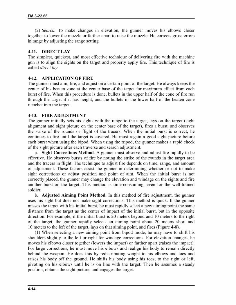
FM 3-22.68
4-14
(2) Search. To make changes in elevation, the gunner moves his elbows closertogether to lower the muzzle or farther apart to raise the muzzle. He corrects gross errorsin range by adjusting the range setting.
4-11. DIRECT LAYThe simplest, quickest, and most effective technique of delivering fire with the machinegun is to align the sights on the target and properly apply fire. This technique of fire iscalled direct lay.
4-12. APPLICATION OF FIREThe gunner must aim, fire, and adjust on a certain point of the target. He always keeps thecenter of his beaten zone at the center base of the target for maximum effect from eachburst of fire. When this procedure is done, bullets in the upper half of the cone of fire runthrough the target if it has height, and the bullets in the lower half of the beaten zonericochet into the target.
4-13. FIRE ADJUSTMENTThe gunner initially sets his sights with the range to the target, lays on the target (sightalignment and sight picture on the center base of the target), fires a burst, and observesthe strike of the rounds or flight of the tracers. When the initial burst is correct, hecontinues to fire until the target is covered. He must regain a good sight picture beforeeach burst when using the bipod. When using the tripod, the gunner makes a rapid checkof the sight picture after each traverse and search adjustment.
a. Sight Corrections Method. A gunner must observe and adjust fire rapidly to beeffective. He observes bursts of fire by noting the strike of the rounds in the target areaand the tracers in flight. The technique to adjust fire depends on time, range, and amountof adjustment. These factors assist the gunner in determining whether or not to makesight corrections or adjust position and point of aim. When the initial burst is notcorrectly placed, the gunner may change the elevation and windage on the sights and fireanother burst on the target. This method is time-consuming, even for the well-trainedsoldier.
b. Adjusted Aiming Point Method. In this method of fire adjustment, the gunneruses his sight but does not make sight corrections. This method is quick. If the gunnermisses the target with his initial burst, he must rapidly select a new aiming point the samedistance from the target as the center of impact of the initial burst, but in the oppositedirection. For example, if the initial burst is 20 meters beyond and 10 meters to the rightof the target, the gunner rapidly selects an aiming point about 20 meters short and10 meters to the left of the target, lays on that aiming point, and fires (Figure 4-8).
(1) When selecting a new aiming point from bipod mode, he may have to shift hisshoulders slightly to the left or right for windage corrections. For elevation changes, hemoves his elbows closer together (lowers the impact) or farther apart (raises the impact).For large corrections, he must move his elbows and realign his body to remain directlybehind the weapon. He does this by redistributing weight to his elbows and toes andraises his body off the ground. He shifts his body using his toes, to the right or left,pivoting on his elbows until he is on line with the target. Then he assumes a steadyposition, obtains the sight picture, and engages the target.
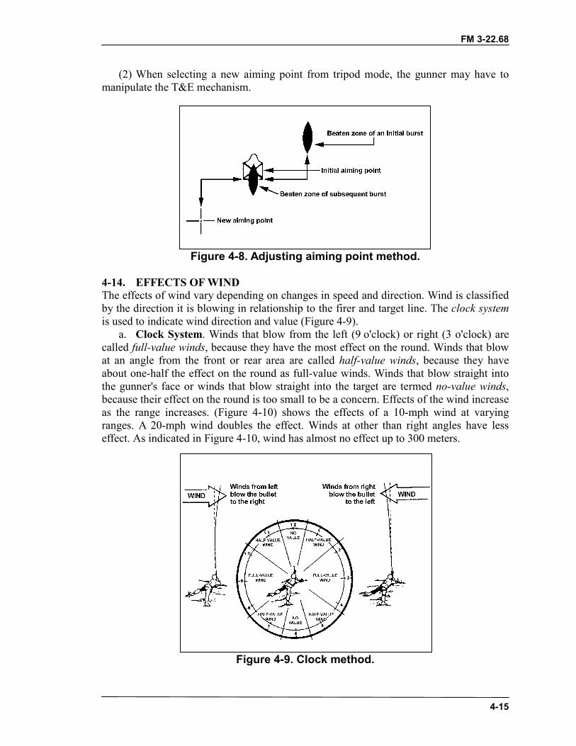
FM 3-22.68
4-15
(2) When selecting a new aiming point from tripod mode, the gunner may have tomanipulate the T&E mechanism.
Figure 4-8. Adjusting aiming point method.
4-14. EFFECTS OF WINDThe effects of wind vary depending on changes in speed and direction. Wind is classifiedby the direction it is blowing in relationship to the firer and target line. The clock systemis used to indicate wind direction and value (Figure 4-9).
a. Clock System. Winds that blow from the left (9 o'clock) or right (3 o'clock) arecalled full-value winds, because they have the most effect on the round. Winds that blowat an angle from the front or rear area are called half-value winds, because they haveabout one-half the effect on the round as full-value winds. Winds that blow straight intothe gunner's face or winds that blow straight into the target are termed no-value winds,because their effect on the round is too small to be a concern. Effects of the wind increaseas the range increases. (Figure 4-10) shows the effects of a 10-mph wind at varyingranges. A 20-mph wind doubles the effect. Winds at other than right angles have lesseffect. As indicated in Figure 4-10, wind has almost no effect up to 300 meters.
Figure 4-9. Clock method.
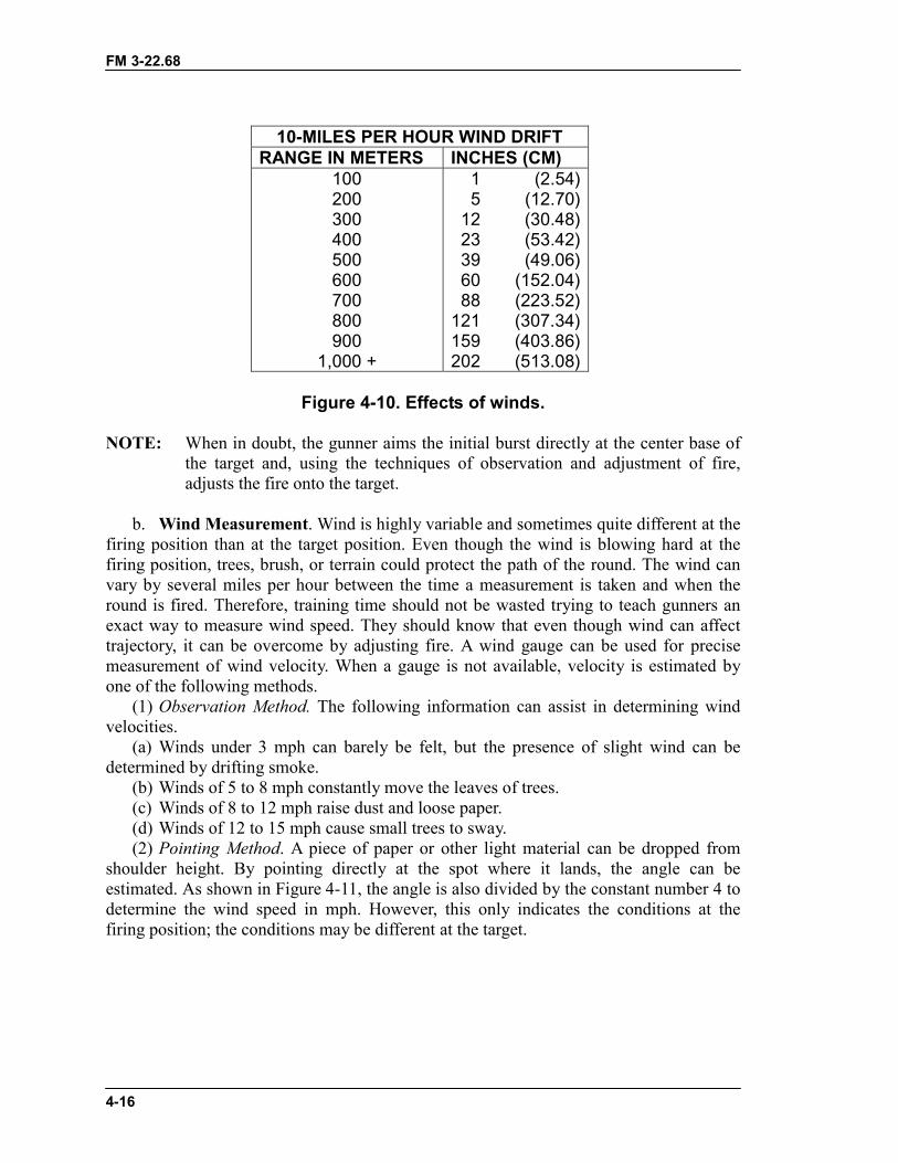
FM 3-22.68
4-16
10-MILES PER HOUR WIND DRIFTRANGE IN METERS INCHES (CM)
100200300400500600700800900
1,000 +
1 (2.54)5 (12.70)
12 (30.48)23 (53.42)39 (49.06)60 (152.04)88 (223.52)
121 (307.34)159 (403.86)202 (513.08)
Figure 4-10. Effects of winds.
NOTE: When in doubt, the gunner aims the initial burst directly at the center base ofthe target and, using the techniques of observation and adjustment of fire,adjusts the fire onto the target.
b. Wind Measurement. Wind is highly variable and sometimes quite different at thefiring position than at the target position. Even though the wind is blowing hard at thefiring position, trees, brush, or terrain could protect the path of the round. The wind canvary by several miles per hour between the time a measurement is taken and when theround is fired. Therefore, training time should not be wasted trying to teach gunners anexact way to measure wind speed. They should know that even though wind can affecttrajectory, it can be overcome by adjusting fire. A wind gauge can be used for precisemeasurement of wind velocity. When a gauge is not available, velocity is estimated byone of the following methods.
(1) Observation Method. The following information can assist in determining windvelocities.
(a) Winds under 3 mph can barely be felt, but the presence of slight wind can bedetermined by drifting smoke.
(b) Winds of 5 to 8 mph constantly move the leaves of trees.(c) Winds of 8 to 12 mph raise dust and loose paper.(d) Winds of 12 to 15 mph cause small trees to sway.(2) Pointing Method. A piece of paper or other light material can be dropped from
shoulder height. By pointing directly at the spot where it lands, the angle can beestimated. As shown in Figure 4-11, the angle is also divided by the constant number 4 todetermine the wind speed in mph. However, this only indicates the conditions at thefiring position; the conditions may be different at the target.
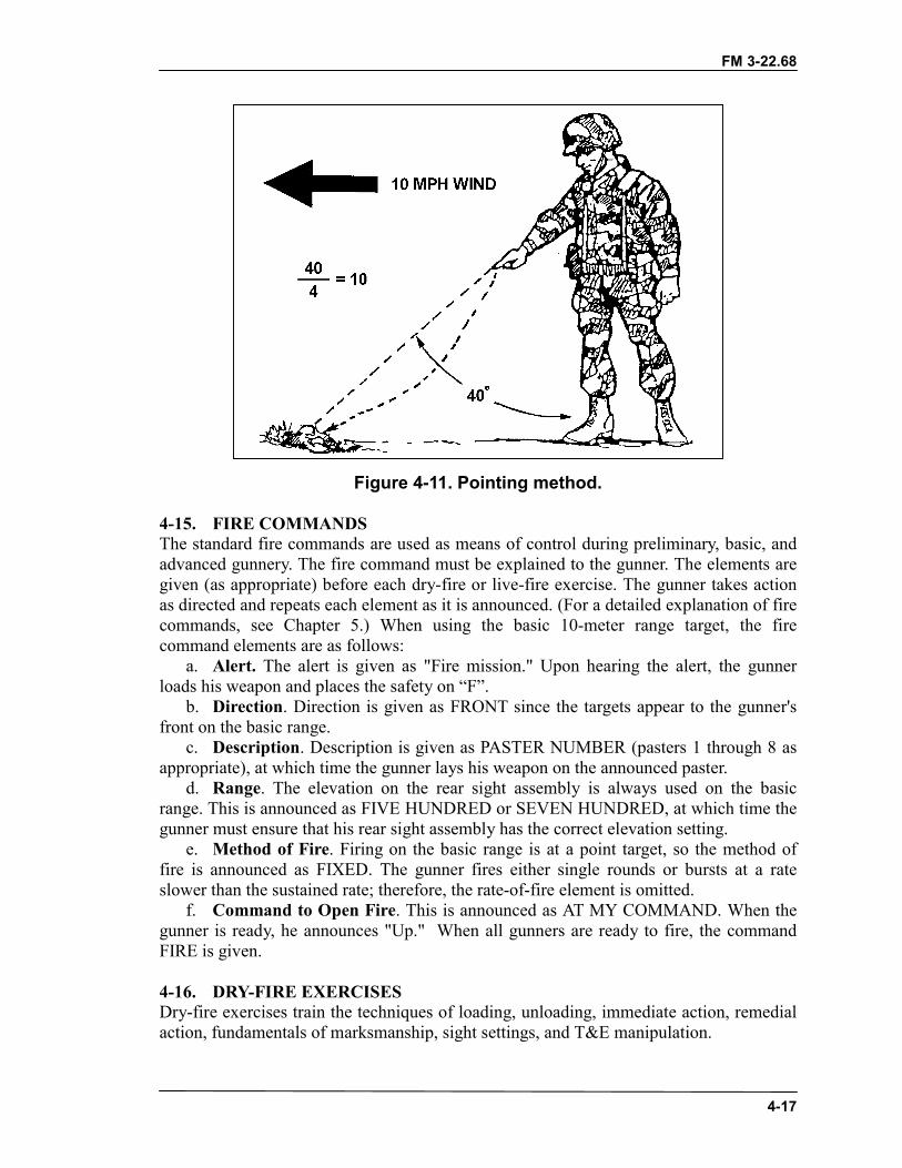
FM 3-22.68
4-17
Figure 4-11. Pointing method.
4-15. FIRE COMMANDSThe standard fire commands are used as means of control during preliminary, basic, andadvanced gunnery. The fire command must be explained to the gunner. The elements aregiven (as appropriate) before each dry-fire or live-fire exercise. The gunner takes actionas directed and repeats each element as it is announced. (For a detailed explanation of firecommands, see Chapter 5.) When using the basic 10-meter range target, the firecommand elements are as follows:
a. Alert. The alert is given as "Fire mission." Upon hearing the alert, the gunnerloads his weapon and places the safety on “F”.
b. Direction. Direction is given as FRONT since the targets appear to the gunner'sfront on the basic range.
c. Description. Description is given as PASTER NUMBER (pasters 1 through 8 asappropriate), at which time the gunner lays his weapon on the announced paster.
d. Range. The elevation on the rear sight assembly is always used on the basicrange. This is announced as FIVE HUNDRED or SEVEN HUNDRED, at which time thegunner must ensure that his rear sight assembly has the correct elevation setting.
e. Method of Fire. Firing on the basic range is at a point target, so the method offire is announced as FIXED. The gunner fires either single rounds or bursts at a rateslower than the sustained rate; therefore, the rate-of-fire element is omitted.
f. Command to Open Fire. This is announced as AT MY COMMAND. When thegunner is ready, he announces "Up." When all gunners are ready to fire, the commandFIRE is given.
4-16. DRY-FIRE EXERCISESDry-fire exercises train the techniques of loading, unloading, immediate action, remedialaction, fundamentals of marksmanship, sight settings, and T&E manipulation.
FM 3-22.68
4-18
a. Ammunition. These exercises may be conducted using blank or dummyammunition and should be conducted using fire commands when appropriate. If the blankfiring attachment is used, safety restrictions for its use must be enforced. While thegunner performs the tasks, the assistant gunner�
� Checks the sight setting and initial lay.� Checks the gunner's position.� Ensures the gunner simulates firing before adjusting his position.� Checks for proper body adjustment or manipulation of T&E.� Critiques the gunner at the end of the exercise.
b. Loading and Unloading Exercises. The procedures for loading and unloadingare prescribed in Chapter’s 1, 2 and 3. They should be reinforced using dummyammunition. This training instills confidence and proficiency in the operation of theweapon. It also provides training in clearing the weapon.
c. Immediate Action and Remedial Action Exercise. This exercise is conductedusing linked dummy rounds and the basic machine gun target. The instructor should usesalvage links to link the dummy rounds together. The gunner�
(1) Loads the weapon with dummy ammunition and aims at one of the aiming pasterson the basic machine gun target.
(2) Being conscious of the sight picture, pulls the trigger and the bolt goes forward(simulate firing the weapon). If the sight picture is disturbed, checks his position andgrip, and maintains better control of the weapon.
(3) If he has a stoppage, applies immediate action procedures and continues to fire.(4) If immediate action has failed, applies remedial action procedures and continue to
fire.d. Operational Exercise. The gunner aims and simulates firing each dummy round
at the aiming paster on the basic machine gun target.(1) Observes the sight picture through the feeding, locking, and firing cycle. (This
provides feedback on his ability to maintain and hold the sight picture.)(2) If at the completion of the firing cycle there is significant movement of the sight
picture, his position is not steady enough or the tripod is not stable.(3) Applies immediate action after firing each shot to extract and eject the dummy
cartridge, and returns the bolt to the cocked position. Returns the cocking handle to theforward position.
e. Sight Setting and Sight Change Exercises. These exercises are designed to trainthe gunner in the operation and adjustment of the rear sight, and making corrections inelevation and windage on the machine gun.
WARNINGThe M240B is carried loaded with the bolt locked to the rear intactical situations where noise discipline is critical to the successof the mission. Trained gun crews are the only personnelauthorized to load the M240B and only when command directs thecrew to do so. During normal training exercises, the M240B isloaded and carried with the bolt in the forward position.
FM 3-22.68
4-19
(1) For large adjustments in elevation (range), the gunner manipulates the rear sightto achieve different range settings. For fine adjustments in elevation, the gunner rotatesthe elevation knob for the machine gun.
(2) To make adjustments for windage, the gunner traverses the rear sight across thewindage scale for the machine gun.
f. Practice. Before the dry-fire proficiency examination, soldiers should practice thetasks until they become proficient.
g. Traversing and Searching Exercise. After the gunner knows the principles ofsighting and aiming and can assume a satisfactory firing position, he learns how to makeminor and major body position changes to obtain an accurate initial lay. He practicesshifting the direction of the weapon to successive points by moving his body. The basicmachine gun target is placed 10 meters from the weapon for this exercise.
(1) Makes adjustments for large shifts in direction by using his elbows-and-toestechnique described earlier. Makes small changes in direction by adjusting his shoulders.
(2) Makes major elevation changes by adjusting the range setting on the rear sight.Makes minor elevation changes by adjusting his elbows.
(3) Traverses and searches the target by sighting on the initial aiming paster (number5 or 6) and then shifting to each of the other pasters in order (5 through 6 or its reverse).
(4) Upon receiving a fire command, the gunner repeats the instructions, sets thesights, lays the weapon on the designated paster, assumes the correct position, and reportsup.
(5) At the command FIRE, the gunner simulates firing two single shots, then shifts tothe next paster and simulates firing until the exercise is complete.
h. T&E Manipulation Exercise. After the gunner understands the principles ofsighting and aiming and can assume a satisfactory firing position, he is instructed inmanipulating the tripod-mounted machine gun to obtain an accurate initial lay. He istaught to shift the direction of the weapon to successive points with proficiency. Thebasic machine gun target is placed 10 meters from the weapon for this exercise.
(1) Makes large shifts in direction by releasing the traversing slide lock lever andmoving the slide to the right or left. Makes minor changes in direction by using thetraversing handwheel. (One click on the handwheel moves the strike of the round 1 cm onthe target.)
(2) Adjusts for elevation by rotating the elevating handwheel with his left hand.(3) Traverses and searches the target by laying on the initial aiming paster (number 5
or 6) and then shifts to each of the other pasters in order (5 through 6 or its reverse). (Allmajor shifts in traverse are accomplished by loosening the traversing slide lockdinglever.) When shifting from pasters number 7 through 8 or 8 through 7, uses the traversinghandwheel.
(4) Upon receiving the command, the gunner repeats the instructions, sets the sights,lays the weapon on the designated paster, assumes the firing position, and reports UP.
(5) At the command FIRE, the gunner repeats the command, simulates firing twosingle shots, then shifts to the next paster and simulates firing until the exercise iscompleted.
i. Dry-Fire Proficiency (Performance) Examination. A gunner must demonstrateskill in all the tasks of the dry-fire proficiency examination before he is allowed to
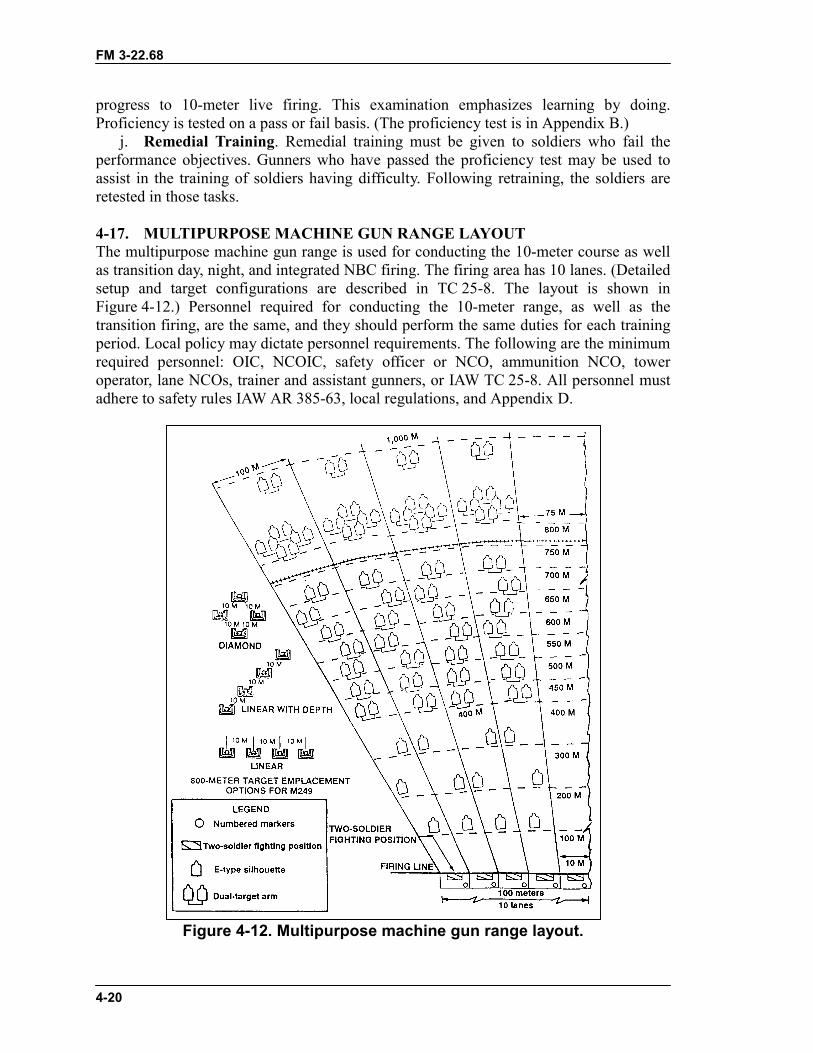
FM 3-22.68
4-20
progress to 10-meter live firing. This examination emphasizes learning by doing.Proficiency is tested on a pass or fail basis. (The proficiency test is in Appendix B.)
j. Remedial Training. Remedial training must be given to soldiers who fail theperformance objectives. Gunners who have passed the proficiency test may be used toassist in the training of soldiers having difficulty. Following retraining, the soldiers areretested in those tasks.
4-17. MULTIPURPOSE MACHINE GUN RANGE LAYOUTThe multipurpose machine gun range is used for conducting the 10-meter course as wellas transition day, night, and integrated NBC firing. The firing area has 10 lanes. (Detailedsetup and target configurations are described in TC 25-8. The layout is shown inFigure 4-12.) Personnel required for conducting the 10-meter range, as well as thetransition firing, are the same, and they should perform the same duties for each trainingperiod. Local policy may dictate personnel requirements. The following are the minimumrequired personnel: OIC, NCOIC, safety officer or NCO, ammunition NCO, toweroperator, lane NCOs, trainer and assistant gunners, or IAW TC 25-8. All personnel mustadhere to safety rules IAW AR 385-63, local regulations, and Appendix D.
Figure 4-12. Multipurpose machine gun range layout.
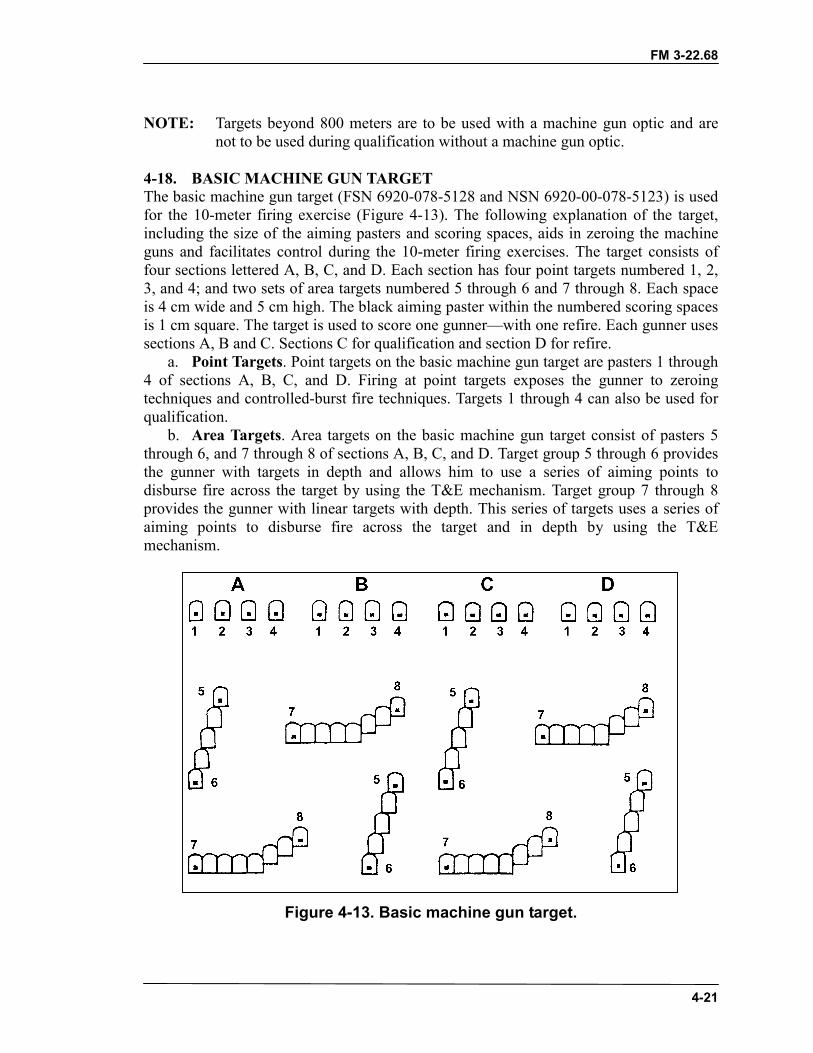
FM 3-22.68
4-21
NOTE: Targets beyond 800 meters are to be used with a machine gun optic and arenot to be used during qualification without a machine gun optic.
4-18. BASIC MACHINE GUN TARGETThe basic machine gun target (FSN 6920-078-5128 and NSN 6920-00-078-5123) is usedfor the 10-meter firing exercise (Figure 4-13). The following explanation of the target,including the size of the aiming pasters and scoring spaces, aids in zeroing the machineguns and facilitates control during the 10-meter firing exercises. The target consists offour sections lettered A, B, C, and D. Each section has four point targets numbered 1, 2,3, and 4; and two sets of area targets numbered 5 through 6 and 7 through 8. Each spaceis 4 cm wide and 5 cm high. The black aiming paster within the numbered scoring spacesis 1 cm square. The target is used to score one gunner—with one refire. Each gunner usessections A, B and C. Sections C for qualification and section D for refire.
a. Point Targets. Point targets on the basic machine gun target are pasters 1 through4 of sections A, B, C, and D. Firing at point targets exposes the gunner to zeroingtechniques and controlled-burst fire techniques. Targets 1 through 4 can also be used forqualification.
b. Area Targets. Area targets on the basic machine gun target consist of pasters 5through 6, and 7 through 8 of sections A, B, C, and D. Target group 5 through 6 providesthe gunner with targets in depth and allows him to use a series of aiming points todisburse fire across the target by using the T&E mechanism. Target group 7 through 8provides the gunner with linear targets with depth. This series of targets uses a series ofaiming points to disburse fire across the target and in depth by using the T&Emechanism.
Figure 4-13. Basic machine gun target.
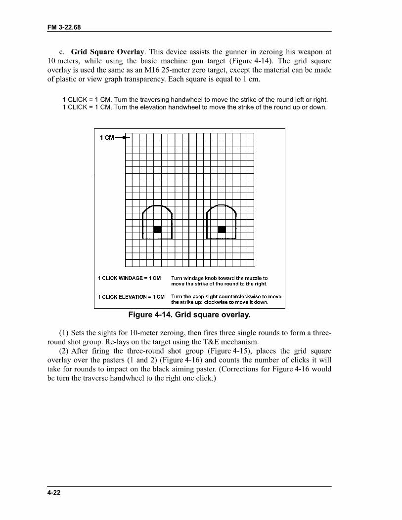
FM 3-22.68
4-22
c. Grid Square Overlay. This device assists the gunner in zeroing his weapon at10 meters, while using the basic machine gun target (Figure 4-14). The grid squareoverlay is used the same as an M16 25-meter zero target, except the material can be madeof plastic or view graph transparency. Each square is equal to 1 cm.
Figure 4-14. Grid square overlay.
(1) Sets the sights for 10-meter zeroing, then fires three single rounds to form a three-round shot group. Re-lays on the target using the T&E mechanism.
(2) After firing the three-round shot group (Figure 4-15), places the grid squareoverlay over the pasters (1 and 2) (Figure 4-16) and counts the number of clicks it willtake for rounds to impact on the black aiming paster. (Corrections for Figure 4-16 wouldbe turn the traverse handwheel to the right one click.)
1 CLICK = 1 CM. Turn the traversing handwheel to move the strike of the round left or right.1 CLICK = 1 CM. Turn the elevation handwheel to move the strike of the round up or down.
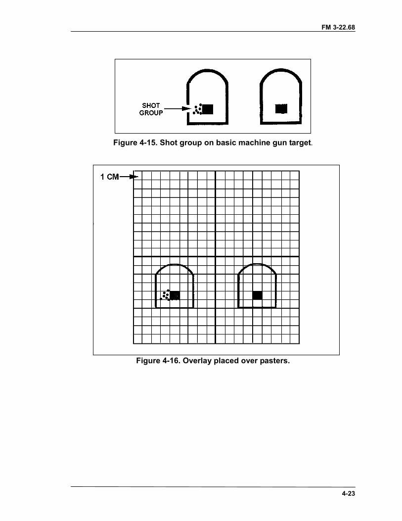
FM 3-22.68
4-23
Figure 4-15. Shot group on basic machine gun target.
Figure 4-16. Overlay placed over pasters.
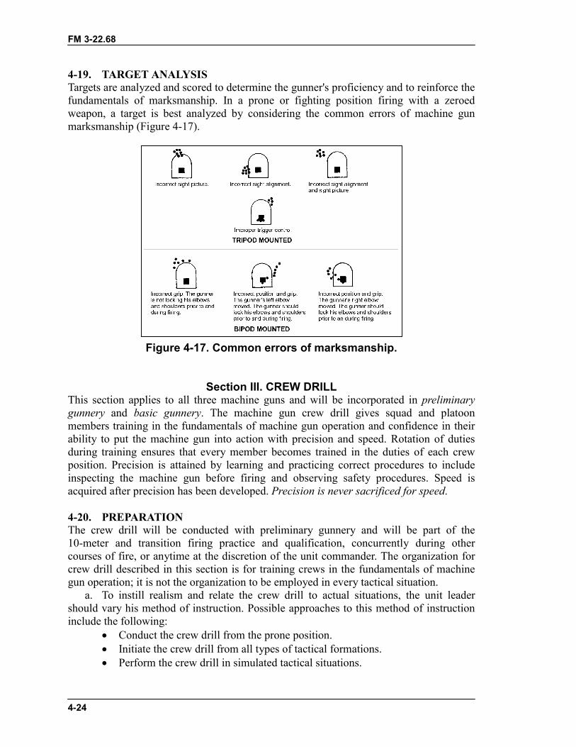
FM 3-22.68
4-24
4-19. TARGET ANALYSISTargets are analyzed and scored to determine the gunner's proficiency and to reinforce thefundamentals of marksmanship. In a prone or fighting position firing with a zeroedweapon, a target is best analyzed by considering the common errors of machine gunmarksmanship (Figure 4-17).
Figure 4-17. Common errors of marksmanship.
Section III. CREW DRILLThis section applies to all three machine guns and will be incorporated in preliminarygunnery and basic gunnery. The machine gun crew drill gives squad and platoonmembers training in the fundamentals of machine gun operation and confidence in theirability to put the machine gun into action with precision and speed. Rotation of dutiesduring training ensures that every member becomes trained in the duties of each crewposition. Precision is attained by learning and practicing correct procedures to includeinspecting the machine gun before firing and observing safety procedures. Speed isacquired after precision has been developed. Precision is never sacrificed for speed.
4-20. PREPARATIONThe crew drill will be conducted with preliminary gunnery and will be part of the10-meter and transition firing practice and qualification, concurrently during othercourses of fire, or anytime at the discretion of the unit commander. The organization forcrew drill described in this section is for training crews in the fundamentals of machinegun operation; it is not the organization to be employed in every tactical situation.
a. To instill realism and relate the crew drill to actual situations, the unit leadershould vary his method of instruction. Possible approaches to this method of instructioninclude the following:
� Conduct the crew drill from the prone position.� Initiate the crew drill from all types of tactical formations.� Perform the crew drill in simulated tactical situations.
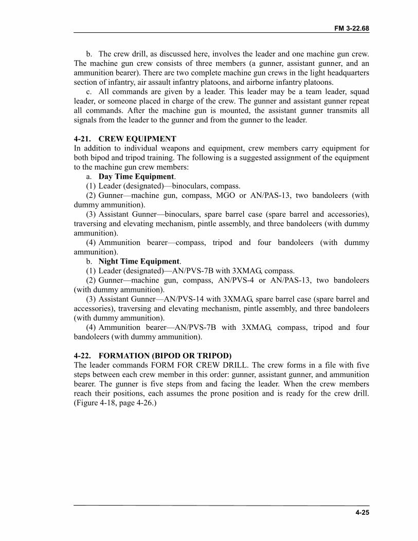
FM 3-22.68
4-25
b. The crew drill, as discussed here, involves the leader and one machine gun crew.The machine gun crew consists of three members (a gunner, assistant gunner, and anammunition bearer). There are two complete machine gun crews in the light headquarterssection of infantry, air assault infantry platoons, and airborne infantry platoons.
c. All commands are given by a leader. This leader may be a team leader, squadleader, or someone placed in charge of the crew. The gunner and assistant gunner repeatall commands. After the machine gun is mounted, the assistant gunner transmits allsignals from the leader to the gunner and from the gunner to the leader.
4-21. CREW EQUIPMENTIn addition to individual weapons and equipment, crew members carry equipment forboth bipod and tripod training. The following is a suggested assignment of the equipmentto the machine gun crew members:
a. Day Time Equipment.(1) Leader (designated)—binoculars, compass.(2) Gunner—machine gun, compass, MGO or AN/PAS-13, two bandoleers (with
dummy ammunition).(3) Assistant Gunner—binoculars, spare barrel case (spare barrel and accessories),
traversing and elevating mechanism, pintle assembly, and three bandoleers (with dummyammunition).
(4) Ammunition bearer—compass, tripod and four bandoleers (with dummyammunition).
b. Night Time Equipment.(1) Leader (designated)—AN/PVS-7B with 3XMAG, compass.(2) Gunner—machine gun, compass, AN/PVS-4 or AN/PAS-13, two bandoleers
(with dummy ammunition).(3) Assistant Gunner—AN/PVS-14 with 3XMAG, spare barrel case (spare barrel and
accessories), traversing and elevating mechanism, pintle assembly, and three bandoleers(with dummy ammunition).
(4) Ammunition bearer—AN/PVS-7B with 3XMAG, compass, tripod and fourbandoleers (with dummy ammunition).
4-22. FORMATION (BIPOD OR TRIPOD)The leader commands FORM FOR CREW DRILL. The crew forms in a file with fivesteps between each crew member in this order: gunner, assistant gunner, and ammunitionbearer. The gunner is five steps from and facing the leader. When the crew membersreach their positions, each assumes the prone position and is ready for the crew drill.(Figure 4-18, page 4-26.)
FM 3-22.68
4-26
Figure 4-18. Crew in ready position.
4-23. CROSS-TRAINING PROCEDURESDuties are rotated during the crew drill to train each soldier in the duties of all crewmembers. The command to rotate duties is FALL OUT, GUNNER. At this command, thegunner becomes the ammunition bearer, the assistant gunner becomes the gunner, and theammunition bearer becomes the assistant gunner. When crew members have assumedtheir new positions, they call out their new duties in order: AMMUNITION BEARER,ASSISTANT GUNNER, GUNNER.
4-24. INSPECTION FOR BIPOD FIREAn inspection of equipment is made at the beginning of each exercise.
a. Command. After the crew is formed for crew drill, the leader commandsINSPECT EQUIPMENT BEFORE FIRING, BIPOD. At the command, each crewmember inspects his equipment as explained below.
(1) Inspection by Gunner. The gunner inspects the ammunition first. He ensures thatthe ammunition is properly linked and free of dirt and corrosion, and that the double linkis up (ready for loading). After he inspects the ammunition, he places the cloth slingsover his shoulder (except for one bandoleer, which he prepares for loading). He theninspects the machine gun and takes his position parallel to the machine gun (his head online with the feed tray). The night personnel also check the AN/PVS-4 or AN/PAS-13.
(a) Holding the machine gun with his left hand, using his right hand he lowers thebipod legs and then rest the machine gun on the bipod.
(b) Attaches the bandoleer to the machine gun.(c) Places the safety on “F”, pulls the cocking handle to the rear, places the safety on
“S”, returns the cocking handle to the forward position, raises the cover assembly.(d) Calls for the cleaning rod and receives it from the assistant gunner.(e) Crawls forward, then runs the cleaning rod through the barrel to ensure it is clear.(f) Checks the flash suppressor for cracks.(g) Checks the front sight for tightness and for damage to the blade.(h) Checks the carrying handle to ensure that it can be positioned so it will not be in
the way during aiming and firing.(i) Ensures that the barrel is securely locked to the receiver.(j) Returns the cleaning rod to the assistant gunner.(k) Moves to the rear of the machine gun and checks the moving parts in the feed
cover.
FM 3-22.68
4-27
� Ensures that the feed cam is clean and properly lubricated.� Pushes back and forth on the feed cam to check for freedom of movement.� Pushes on the belt feed pawl to ensure that it has spring tension.� Pushes on the cartridge guides to ensure that they a have spring tension.
(l) Pushes the belt holding pawl to ensure that it has spring tension.(m)Lowers and latches the cover (without inserting the belt).(n) Pulls the trigger to check the functioning of the safety.(o) Places the safety on “F”, pulls the cocking handle to the rear, pulls the trigger,
eases the bolt forward manually with the cocking handle.(p) Checks the rear sight.(2) Inspection by Assistant Gunner. Remaining in a prone position, the assistant
gunner begins by inspecting his ammunition. He takes the cleaning rod from the carryingcase and assembles the cleaning rod. He then takes the traversing and elevatingmechanism from the case and prepares it as follows. Night will also check AN/PVS-14with 3X MAG.
(a) Rotates the elevating handwheel, exposing 1 1/2 inches or the width of twofingers) of threads above the elevating handwheel.
(b) Rotates the traversing slide sleeve, exposing 1 1/2 inches or the width of twofingers) of threads below the elevating handwheel.
(c) Centers the traversing mechanism.(d) Checks the to ensure that the locking mechanism that attach to the machine gun
are present and in working order.(e) Replaces the traversing and elevating mechanism in on the case and removes the
spare barrel from the spare barrel case.(f) Checks the barrel.(g) Checks the flash suppressor for cracks.(h) Checks the front sight for tightness and for damage to the blade.(i) Checks the pintle assembly for proper functioning.(j) Places the spare barrel its case; disassembles the cleaning rod and returns it
accessory pocket; and checks the ruptured cartridge extractor, bore brush, chamber brush,receiver brush, and heat protective mitten for serviceability.
(3) Inspection by Ammunition Bearer. Remaining in a prone position, the ammunitionbearer inspects his ammunition as described above for gunner and assistant gunner. Hethen inspects the tripod, pintle assembly and T&E mechanism. Night personnel alsocheck the AN/PVS-7 with the 3XMAG.
(a) Ensures that the front leg will unfold properly and the rear legs unfold and locksecurely in place with the sleeve latch.
(b) Checks the sleeve latch to ensure that it has spring tension and will function.(c) Checks the pintle assembly to ensure that it is locked into the pintle bushing and
that the pintle rotates freely within the bushing.(d) Checks to ensure that the T&E mechanism will lock on the traversing bar and
move freely when unlocked for major changes in direction.(e) Unlocks the pintle and T&E mechanism from the tripod and return to the assistant
gunner.(f) Folds the rear legs by unlocking the sleeve latch and folds the front leg so that the
tripod is in the carrying position.
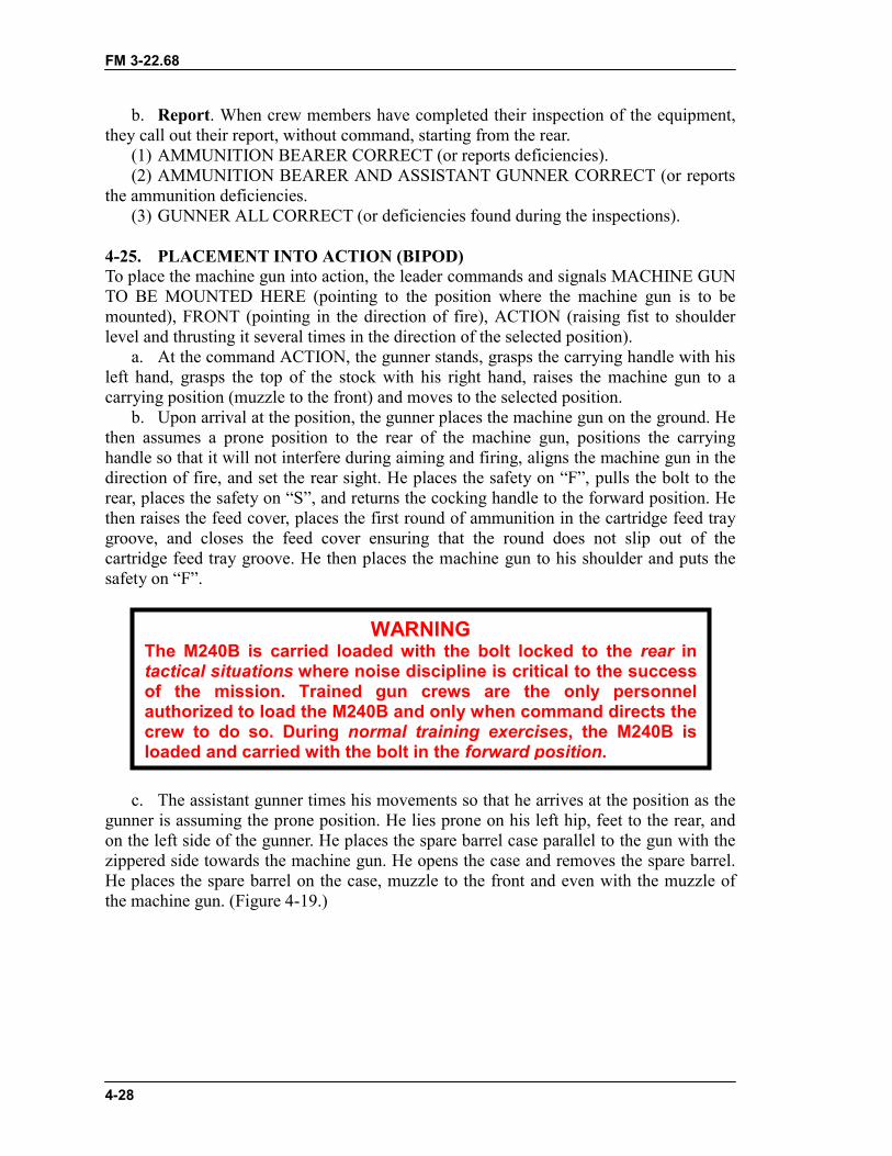
FM 3-22.68
4-28
b. Report. When crew members have completed their inspection of the equipment,they call out their report, without command, starting from the rear.
(1) AMMUNITION BEARER CORRECT (or reports deficiencies).(2) AMMUNITION BEARER AND ASSISTANT GUNNER CORRECT (or reports
the ammunition deficiencies.(3) GUNNER ALL CORRECT (or deficiencies found during the inspections).
4-25. PLACEMENT INTO ACTION (BIPOD)To place the machine gun into action, the leader commands and signals MACHINE GUNTO BE MOUNTED HERE (pointing to the position where the machine gun is to bemounted), FRONT (pointing in the direction of fire), ACTION (raising fist to shoulderlevel and thrusting it several times in the direction of the selected position).
a. At the command ACTION, the gunner stands, grasps the carrying handle with hisleft hand, grasps the top of the stock with his right hand, raises the machine gun to acarrying position (muzzle to the front) and moves to the selected position.
b. Upon arrival at the position, the gunner places the machine gun on the ground. Hethen assumes a prone position to the rear of the machine gun, positions the carryinghandle so that it will not interfere during aiming and firing, aligns the machine gun in thedirection of fire, and set the rear sight. He places the safety on “F”, pulls the bolt to therear, places the safety on “S”, and returns the cocking handle to the forward position. Hethen raises the feed cover, places the first round of ammunition in the cartridge feed traygroove, and closes the feed cover ensuring that the round does not slip out of thecartridge feed tray groove. He then places the machine gun to his shoulder and puts thesafety on “F”.
c. The assistant gunner times his movements so that he arrives at the position as thegunner is assuming the prone position. He lies prone on his left hip, feet to the rear, andon the left side of the gunner. He places the spare barrel case parallel to the gun with thezippered side towards the machine gun. He opens the case and removes the spare barrel.He places the spare barrel on the case, muzzle to the front and even with the muzzle ofthe machine gun. (Figure 4-19.)
WARNINGThe M240B is carried loaded with the bolt locked to the rear intactical situations where noise discipline is critical to the successof the mission. Trained gun crews are the only personnelauthorized to load the M240B and only when command directs thecrew to do so. During normal training exercises, the M240B isloaded and carried with the bolt in the forward position.
FM 3-22.68
4-29
Figure 4-19. Crew members in firing position.
d. The ammunition bearer times his movements so that he arrives at the position asthe assistant gunner is assuming the prone position. He places the folded tripod one stepto the left of the muzzle of the machine gun and on line with the machine gun. Heunslings his bandoleers and places them next to the folded tripod legs. He then lies prone10 meters to the left and on line with the position, provides security, and prepares to fireinto the target area with his rifle.
e. When ready to fire, the gunner puts the safety lever on “F” and reports UP. Theassistant gunner signals READY to the leader.
4-26. PROCEDURES FOR CHANGING THE BARREL (BIPOD)To ensure proficiency and speed in changing barrels, the barrel changing process isincluded in crew drill. When the gunner has reported UP and the assistant gunner hassignaled READY, the leader commands CHANGE BARRELS.
a. The gunner ensures that the bolt is to the rear, puts the safety on “S”, and puts thestock on the ground. Next, he moves his left hand to the top of the stock to ensure theweapon stays parallel to the ground. He puts his right hand under the handguard/forearmassembly help support the machine gun when the assistant gunner removes the barrel.
FM 3-22.68
4-30
b. The assistant gunner (wearing the heat protective mitten) unlocks the barrellocking lever, removes the barrel, and places the barrel on the spare barrel case. He holdsthe spare barrel inserts it into the machine gun.
c. The gunner ensures that the barrel is lock and secured in the receive of themachine gun, moves the safety lever to “F”, assumes the correct firing position, andreports UP. The assistant gunner signals READY to the squad leader.
4-27. REMOVAL FROM ACTION (BIPOD)To take the machine gun out of action, the leader commands and signals OUT OFACTION. The gunner and assistant gunner repeat the command.
a. At the command OUT OF ACTION, the ammunition bearer moves to theposition, slinging his rifle. He picks up and slings the bandoleers that he previously leftthere. He gets the tripod and moves 15 steps to the rear of the machine gun. He liesprone, facing the position with the tripod in front of him.
b. The assistant gunner places spare barrel and the heat protective mitten in the sparebarrel case. Before standing, he closes the spare barrel case enough to retain the sparebarrel and the traversing and elevating mechanism. He moves 10 steps to the rear of theposition and lies prone, facing the position. At this time, he fully closes the spare barrelcase.
c. The gunner places the stock on the ground, ensures that the bolt is to the rear,places the safety on “S”, and raises the feed cover. He removes the ammunition from thetray, puts it into the bandoleer, and closes the bandoleer. The gunner examines thechamber to ensure that it is clear; closes the feed cover; pulls the cocking handle to therear; puts the safety on “F”; pulls the trigger, easing the bolt forward. Standing, he pivotson his right foot; without turning the machine gun, he raises it to his left hip and movesfive steps to the rear. He visually checks to ensure that the ammunition bearer and theassistant gunner are in their positions. He lies prone, facing the position with the machinegun on his right. He folds the bipod legs alongside the barrel and reports UP to the squadleader.
4-28. INSPECTION FOR TRIPOD FIREThe inspection of equipment for tripod training is the same as for bipod training exceptthat the leader's command to start the inspection of equipment is INSPECTEQUIPMENT BEFORE FIRING TRIPOD. Also, the gunner inspects the bipod legs andfolds them to their position alongside the barrel.
4-29. PLACEMENT INTO ACTION (TRIPOD)The leader commands and signals MACHINE GUN TO BE MOUNTED HERE,FRONT, ACTION. (Figure 4-20.)
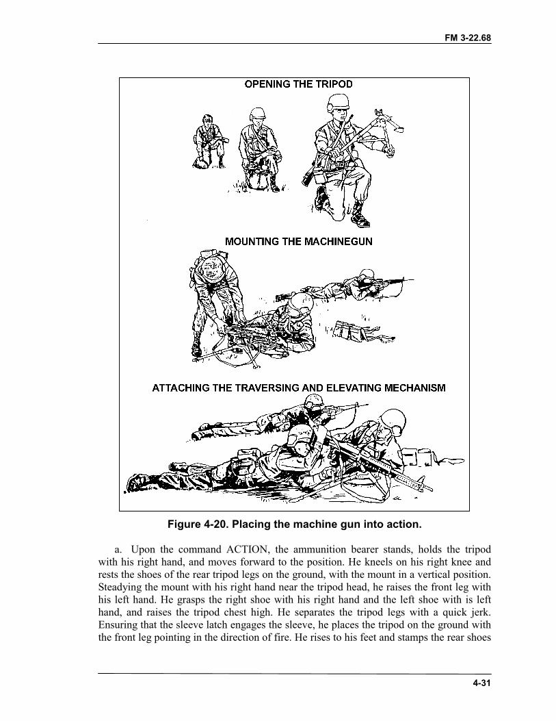
FM 3-22.68
4-31
Figure 4-20. Placing the machine gun into action.
a. Upon the command ACTION, the ammunition bearer stands, holds the tripodwith his right hand, and moves forward to the position. He kneels on his right knee andrests the shoes of the rear tripod legs on the ground, with the mount in a vertical position.Steadying the mount with his right hand near the tripod head, he raises the front leg withhis left hand. He grasps the right shoe with his right hand and the left shoe with is lefthand, and raises the tripod chest high. He separates the tripod legs with a quick jerk.Ensuring that the sleeve latch engages the sleeve, he places the tripod on the ground withthe front leg pointing in the direction of fire. He rises to his feet and stamps the rear shoes
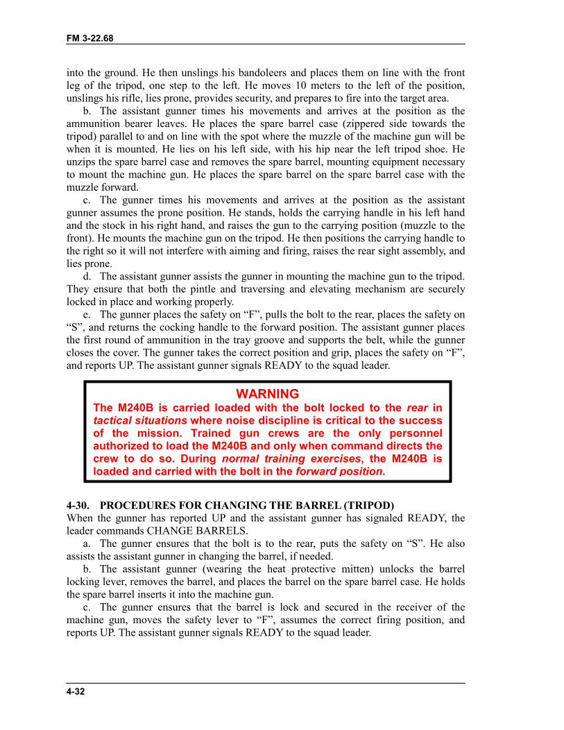
FM 3-22.68
4-32
into the ground. He then unslings his bandoleers and places them on line with the frontleg of the tripod, one step to the left. He moves 10 meters to the left of the position,unslings his rifle, lies prone, provides security, and prepares to fire into the target area.
b. The assistant gunner times his movements and arrives at the position as theammunition bearer leaves. He places the spare barrel case (zippered side towards thetripod) parallel to and on line with the spot where the muzzle of the machine gun will bewhen it is mounted. He lies on his left side, with his hip near the left tripod shoe. Heunzips the spare barrel case and removes the spare barrel, mounting equipment necessaryto mount the machine gun. He places the spare barrel on the spare barrel case with themuzzle forward.
c. The gunner times his movements and arrives at the position as the assistantgunner assumes the prone position. He stands, holds the carrying handle in his left handand the stock in his right hand, and raises the gun to the carrying position (muzzle to thefront). He mounts the machine gun on the tripod. He then positions the carrying handle tothe right so it will not interfere with aiming and firing, raises the rear sight assembly, andlies prone.
d. The assistant gunner assists the gunner in mounting the machine gun to the tripod.They ensure that both the pintle and traversing and elevating mechanism are securelylocked in place and working properly.
e. The gunner places the safety on “F”, pulls the bolt to the rear, places the safety on“S”, and returns the cocking handle to the forward position. The assistant gunner placesthe first round of ammunition in the tray groove and supports the belt, while the gunnercloses the cover. The gunner takes the correct position and grip, places the safety on “F”,and reports UP. The assistant gunner signals READY to the squad leader.
4-30. PROCEDURES FOR CHANGING THE BARREL (TRIPOD)When the gunner has reported UP and the assistant gunner has signaled READY, theleader commands CHANGE BARRELS.
a. The gunner ensures that the bolt is to the rear, puts the safety on “S”. He alsoassists the assistant gunner in changing the barrel, if needed.
b. The assistant gunner (wearing the heat protective mitten) unlocks the barrellocking lever, removes the barrel, and places the barrel on the spare barrel case. He holdsthe spare barrel inserts it into the machine gun.
c. The gunner ensures that the barrel is lock and secured in the receiver of themachine gun, moves the safety lever to “F”, assumes the correct firing position, andreports UP. The assistant gunner signals READY to the squad leader.
WARNINGThe M240B is carried loaded with the bolt locked to the rear intactical situations where noise discipline is critical to the successof the mission. Trained gun crews are the only personnelauthorized to load the M240B and only when command directs thecrew to do so. During normal training exercises, the M240B isloaded and carried with the bolt in the forward position.
FM 3-22.68
4-33
4-31. REMOVAL FROM ACTION (TRIPOD)At the command OUT OF ACTION, the gunner ensures that the bolt is to the rear, placesthe safety on “S”, and raises the cover. The assistant gunner removes the ammunitionfrom the tray, returns it to the bandoleer, and closes the bandoleer. The gunner inspectsthe chamber to ensure that it is clear; closes the cover; pulls the cocking handle to therear; puts the safety on “F”; pulls the trigger, easing the bolt forward. The gunner unlocksthe rear of the machine gun from the tripod.
a. The assistant gunner will assist the gunner in dismounting the rear of the machinegun. He puts the spare barrel and heat protective mitten into the case and closes it enoughto hold the contents. He stands, moves 10 steps to the rear of the position, and lies prone,facing to the front. After receiving all mounting equipment from the ammunition bearer,he puts it in the spare barrel case and fully closes the spare barrel case.
b. After the assistant gunner leaves, the gunner stands, lowers the rear sight, andholds the carrying handle with his left hand. With his right hand, he dismounts the frontof the machine gun from the tripod. Holding the stock with his right hand, he pivots to hisright as he raises the machine gun to the carrying position. He then moves five steps tothe rear of the position and lies prone, facing to the front.
c. The ammunition bearer rises, slings his rifle, moves to the machine gun, andsecures his bandoleers, timing his arrival so that the gunner and assistant gunner will beclear of the tripod. He grasps the tripod with his left hand and moves five steps to the rearof the position. He turns, facing the front, and kneels on his right knee. He places thetripod in a vertical position with the rear shoes on the ground and supports it with hisright hand near the head of the tripod. At this time, he hands the assistant gunner allmounting equipment. He reaches up with his right hand down the right leg, and releasesthe sleeve latch. He then grasps the shoes and closes the tripod legs. He lowers the tripodto the ground, head to the left, lies prone behind it, and reports UP.
4-32. PRONE POSITIONMachine gun crew drill, as it is described in the preceding paragraphs, is an excellenttraining vehicle for the machine gun crew. A continuation or second phase of the crewdrill is outlined in this paragraph. It should be used only as a technique for adding realismto training.
a. Inspecting Equipment Before Firing. The inspection of equipment for crew drillfrom the prone position is the same as that for bipod training and tripod training.
b. Placing the Machine Gun Into Action. The leader commands and signalsMACHINE GUN TO BE MOUNTED HERE, FRONT, ACTION in the same manner asfor bipod training. The procedures for bipod training are the same with oneexception�crew members do not get to their feet and movements are executed in the lowcrawl. Once in position, all actions are performed from the prone position.
c. Training With the Tripod. Upon the command ACTION, the ammunition bearercrawls forward to the designated position and extends the front leg of the tripod.Grasping the rear legs firmly, he emplaces the front leg. Applying downward pressure, heemplaces the rear legs. He then crawls to a position about 10-meters to the left of themachine gun and gets into a good firing position with his rifle.
(1) The assistant gunner crawls forward, timing his movement to arrive as theammunition bearer leaves. Positioning himself on the left side and facing the tripod, he
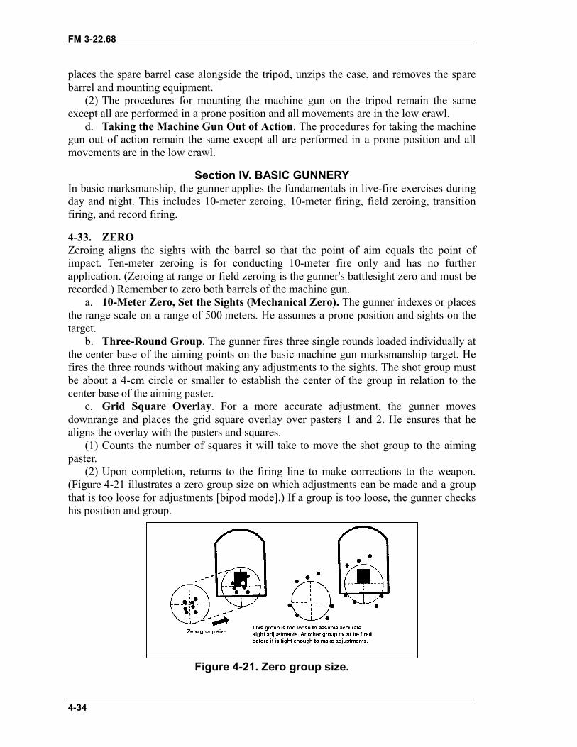
FM 3-22.68
4-34
places the spare barrel case alongside the tripod, unzips the case, and removes the sparebarrel and mounting equipment.
(2) The procedures for mounting the machine gun on the tripod remain the sameexcept all are performed in a prone position and all movements are in the low crawl.
d. Taking the Machine Gun Out of Action. The procedures for taking the machinegun out of action remain the same except all are performed in a prone position and allmovements are in the low crawl.
Section IV. BASIC GUNNERYIn basic marksmanship, the gunner applies the fundamentals in live-fire exercises duringday and night. This includes 10-meter zeroing, 10-meter firing, field zeroing, transitionfiring, and record firing.
4-33. ZEROZeroing aligns the sights with the barrel so that the point of aim equals the point ofimpact. Ten-meter zeroing is for conducting 10-meter fire only and has no furtherapplication. (Zeroing at range or field zeroing is the gunner's battlesight zero and must berecorded.) Remember to zero both barrels of the machine gun.
a. 10-Meter Zero, Set the Sights (Mechanical Zero). The gunner indexes or placesthe range scale on a range of 500 meters. He assumes a prone position and sights on thetarget.
b. Three-Round Group. The gunner fires three single rounds loaded individually atthe center base of the aiming points on the basic machine gun marksmanship target. Hefires the three rounds without making any adjustments to the sights. The shot group mustbe about a 4-cm circle or smaller to establish the center of the group in relation to thecenter base of the aiming paster.
c. Grid Square Overlay. For a more accurate adjustment, the gunner movesdownrange and places the grid square overlay over pasters 1 and 2. He ensures that healigns the overlay with the pasters and squares.
(1) Counts the number of squares it will take to move the shot group to the aimingpaster.
(2) Upon completion, returns to the firing line to make corrections to the weapon.(Figure 4-21 illustrates a zero group size on which adjustments can be made and a groupthat is too loose for adjustments [bipod mode].) If a group is too loose, the gunner checkshis position and group.
Figure 4-21. Zero group size.
FM 3-22.68
4-35
d. Windage Correction. If the center of the group is to the left or right of the blackaiming paster, the gunner must correct for windage.
e. Elevation Correction. If the center of the shot group is above or below of theblack aiming paster, the gunner must correct for elevation.
f. Confirmation. The gunner fires another three-shot group (loaded singly) aftermaking his corrections for windage and elevation. If the center of the group is still off theaiming point, he adjusts further until the group is centered on the point of aim.
g. Recording of Zero. There is no reason to record the 10-meter zero, because itapplies only to firing at the 10-meter basic machine gun target.
NOTE: Remember to zero both barrels.
4-34. FIELD ZEROA gunner must know how to zero the machine gun at distance. He should select a knowndistance target between 300 and 700 meters. As the range increases, it becomes moredifficult to determine where the center of the beaten zone is in relation to the target.Therefore, the 500-meter target on the transition range is recommended because of theease of determining adjustments.
a. Setting of the Sights. The gunner uses the same procedures as for 10-meterzeroing except that he places the rear sight on the range to the target. The recommendedrange is 500 meters.
b. Burst. Fire a burst of 5 to 7 rounds for the M249 or 7 to 9 for the M60/M240B.The gunner assumes a good stable position and fires bursts of 5 to 7 rounds for the M249or 7 to 9 for the M60/M240B at the center base of the target and notes where the burststrikes.
c. Correction for Windage. If the center of the beaten zone is to the left or right ofthe target, he corrects for windage. He adjusts the windage accordingly.
d. Correction for Elevation. If the center of the beaten zone is high or low inrelation to the target, he corrects for elevation. Because determining that relationship isdifficult, the gunner relies on trial and error to gain sufficient experience in makingreliable estimates. He makes corrections in the same manner as 10-meter zeroing.
e. Confirmation. After making corrections for windage and elevation, the gunnerfires confirming bursts of 5 to 7 rounds for the M249 or 7 to 9 rounds for theM60/M240B. If the target is not hit, he repeats the procedures.
WARNINGThe M240B is carried loaded with the bolt locked to the rear intactical situations where noise discipline is critical to the successof the mission. Trained gun crews are the only personnelauthorized to load the M240B and only when command directs thecrew to do so. During normal training exercises, the M240B isloaded and carried with the bolt in the forward position.
FM 3-22.68
4-36
f. Recording of Zero. Upon confirming the zero, the gunner records it by countingthe number of clicks he moved the sight for windage and elevation from the initialsetting.
4-35. 10-METER FIRINGThe 10-meter firing trains the gunner to apply the fundamentals of machine gunmarksmanship in live-fire exercises. It familiarizes the soldier with the weapon'scharacteristics, noise, and recoil. It instills in the soldier confidence in his weapon. Eachgunner learns to zero his machine gun, conducts crew drill, controlled-burst fire at pointtargets, and uses traverse and search techniques of fire at area targets. The 10-meter firingis conducted on a 10-meter range or a multipurpose range using the basic machine guntarget. These exercises are fired with the machine gun on the bipod from both the proneposition and the fighting position and with the tripod from prone and fighting positions.The 10-meter firing exercises are for practice as well as part of record qualification.All 10-meter firing exercises are recorded and scored to provide the gunner anassessment of his performance. The 10-meter firing is conducted IAW Firing Table I(Table 4-2, page 4-42). There are ten tasks.
a. Task 1—Zero Bipod. The gunner fires single shots to determine his weapon'szero for 10 meters. This task reinforces the dry-fire experience and allows the gunner topractice loading, while providing the most accurate and tight shot group obtainable. (A1and A2)
b. Task 2—Controlled-Burst Fire Bipod Fixed. Using point targets, the gunnerfires bursts of 5 to 7 rounds for the M249 or 7 to 9 rounds for the M60/M240B. This taskexposes the gunner to automatic fire and the action of the weapon and at the same timeintroduces trigger control. (A3 and A4)
c. Task 3—Controlled-Burst Fire Bipod Fixed. This task requires the gunner tomake body position to engage area targets in depth, to use controlled-burst firing, and touse a series of aiming points to disburse fire across the target. (A5 and A6)
d. Task 4—Controlled-Burst Fire Bipod Fixed. This task requires the gunner tomake position changes to engage linear targets with depth, to use controlled-burst firing,and to use a series of aiming points to disburse fire across the target. (A7 and A8)
e. Task 5—Zero Tripod. The gunner fires single shots to determine his weapon'szero for 10 meters. This task reinforces the dry-fire experience and allows the gunner topractice loading, while providing the most accurate and tight shot group obtainable. (B1and B2)
f. Task 6—Controlled-Burst Fire Tripod. Using point targets, the gunner firesbursts of 5 to 7 rounds for the M249 or 7 to 9 rounds for the M60/M240B. This taskexposes the gunner to automatic fire and the action of the weapon and at the same timeintroduces trigger control. (B1 through B4)
g. Task 7—Traverse and Search Fire. This task requires the gunner to makeposition changes or manipulate the T&E mechanism to engage linear targets with depth,to use controlled-burst firing, and to use a series of aiming points to disburse fire acrossthe target. (B7 through B8)
h. Task 8—Traverse and Search Fire. This task requires the gunner to make bodyposition changes or manipulate the T&E mechanism to engage area targets in depth, to
FM 3-22.68
4-37
use controlled-burst firing, and to use a series of aiming points to disburse fire across thetarget, while wearing a protective mask and gloves. (B5 through B6)
i. Task 9—Search and Traverse Fire Qualification. This task requires the gunnerto make position changes or manipulate the T&E mechanism to engage area targets indepth during timed conditions. (C5 through C6)
j. Task 10—Traverse and Search Fire Qualification. This task requires thegunner to engage area targets with width and depth, while making position changes ormanipulating the T&E mechanism during timed conditions. (C7 through C8)
4-36. 10-METER CONDUCT OF FIREThe gunners are instructed on the objectives and fundamentals of firing from the bipodand tripod-supported prone or fighting positions, on fire commands used on the basicrange, on the basic machine gun marksmanship target, and on analyzing and scoring thetarget. The unit is organized in firing orders based on range constraints. Each firing ordershould consist of a gunner and an assistant gunner. The assistant gunner assists thegunner during prefire checks and zeroing. The assistant gunner also relays signals to thetower operator, checks the gunner's position, and assists him. During qualification, anassistant gunner is not used. The ten tasks are fired in the following manner:
a. Task 1—Bipod, Zero.(1) The tower operator gives the command MACHINE GUN TO BE MOUNTED
HERE (weapon squad leader’s pointing to the firing points on the 10-meter line), FRONT(weapon squad leader’s pointing to the 10-meter targets), ACTION.
(2) At the command ACTION the machine gun crew conducts, placing the machinegun into action (bipod mode)
(3) The gunner prepares the rear sight for zeroing and checks the front sight.(4) The gunner assumes a good position.(5) The tower operator instructs the gunner to prepare a single round.(6) The following fire command is given. The gunner and assistant gunner repeat
each element of the fire command as it is given.FIRE MISSION (The gunner loads and moves the safety to “F”.)FRONT (The gunner focuses on the target or target area.)PASTER A ONE (The gunner locates target.)FIVE HUNDRED (The gunner adjusts sights and acquires the sight picture.)FIXED, ONE ROUND (The gunner is given the method of fire.)COMMENCE FIRING (The gunner fires on command from tower operator, butwhen ready.)
NOTE: Throughout all firing exercises, the gunner performs the appropriate tasksduring each element of the fire command. The number of rounds fired is usedinstead of the rate for METHOD OF FIRE. This is for control. (Omitting therate specifies RAPID fire, which is not desirable for the tasks.)
FM 3-22.68
4-38
(7) The gunner loads one round, obtains the proper sight picture, and gives an UP tothe assistant gunner.
(8) The assistant gunner relays the READY signal to the tower operator.(9) The tower operator gives the command COMMENCE FIRING.(10) The gunner engages paster A1 with three-single shots when he is ready.(11) The gunner moves downrange to observe, mark, and triangulate the shot group.
He makes adjustments as needed.(12) Steps 3 through 10 are repeated, but the gunner fires at paster A2 firing a single
round, then he adjusts.
NOTE: If the gunner should zero his weapon using 9 rounds, he uses the remaining3 rounds to confirm his zero. If he is unable to zero with 12 rounds, he isremoved from the firing line for remedial training.
b. Task 2—Bipod, Controlled-Burst Fire, Fixed.(1) The tower operator instructs the gunner to prepare two 7-round belts (M249) or
two 9-round belts (M60/M240B).(2) When the fire command is given, the gunner and assistant gunner repeat each
element as it is given.FIRE MISSIONFRONTPASTER A THREEFIVE HUNDREDFIXED, FIVE- TO SEVEN-ROUND BURSTS (M249) or SEVEN- TO NINE-ROUND BURSTS (M60/M240B).AT MY COMMAND
(3) The gunner acquires the proper sight picture and gives an UP to the assistantgunner.
WARNINGThe M240B is carried loaded with the bolt locked to the rear intactical situations where noise discipline is critical to the successof the mission. Trained gun crews are the only personnelauthorized to load the M240B and only when command directs thecrew to do so. During normal training exercises, the M240B isloaded and carried with the bolt in the forward position.
WARNINGThe M240B is carried loaded with the bolt locked to the rear intactical situations where noise discipline is critical to the successof the mission. Trained gun crews are the only personnelauthorized to load the M240B and only when command directs thecrew to do so. During normal training exercises, the M240B isloaded and carried with the bolt in the forward position.
FM 3-22.68
4-39
(4) The assistant gunner relays the READY signal to the tower operator.(5) The tower operator gives the command to FIRE.(6) The gunner fires the first burst of 5 to 7 rounds (M249) or 7 to 9 rounds
(M60/M240B) at paster A3.(7) Steps 2 through 6 are repeated, but the gunner fires at paster A4.c. Task 3—Bipod, Controlled-Burst Fire, Fixed.(1) The tower operator instructs the gunner to prepare a 14-round belt (M249) or
18-round belt (M60/M240B).(2) When the fire command is given, the gunner and assistant gunner repeat each
element as it is given.FIRE MISSIONFRONTPASTER A FIVEFIVE HUNDREDTRAVERSE AND SEARCH, FIVE- TO SEVEN-ROUND BURSTS (M249) ORSEVEN- TO NINE-ROUND BURSTS (M60/M240B)AT MY COMMAND
(3) The gunner acquires the proper sight picture and gives an UP to the assistantgunner.
(4) The assistant gunner relays the READY signal to the tower operator.(5) The tower operator gives the command to FIRE.(6) The gunner fires the first burst of 5 to 7 (M249) OR 7 TO 9 (M60/M240B) rounds
at paster A5.(7) Steps 2 through 6 are repeated, but the gunner fires at paster A6.d. Task 4—Bipod, Controlled-Burst Fire, Fixed.(1) The tower operator instructs the gunner to prepare 14-round belt (M249) or
18-round belt (M60/M240B).(2) When the fire command is given, the gunner and assistant gunner repeat each
element as it is given. FIRE MISSION
FRONTPASTER A SEVENFIVE HUNDREDTRAVERSE AND SEARCH, FIVE- TO SEVEN-ROUND BURSTS (M249) orSEVEN- TO NINE-ROUND BURSTS (M60/M240B)AT MY COMMAND
(3) The gunner acquires the proper sight picture and gives an UP to the assistantgunner.
(4) The assistant gunner relays the READY signal to the tower operator.(5) The tower operator gives the command to FIRE.(6) The gunner fires the first burst of 5 to 7 rounds (M249) or 7 to 9 rounds
(M60/M240B) at paster A7.(7) Steps 2 through 6 are repeated, but the gunner fires at paster A8.(8) The gunner and assistant gunner moves downrange to observe and analyze his
target and shot groups.
FM 3-22.68
4-40
(9) The Tower operator gives the following command when the gunner and assistantgunner return from downrange. OUT OF ACTION.
(10) At the command OUT OF ACTION the machine gun crew conducts, taking themachine gun out of action (bipod mode)
e. Task 5—Tripod, Zero. If the gunner should zero his weapon in 9 rounds, he usesthe remaining 3 rounds to confirm his zero. If he is unable to zero in 12 rounds, he isremoved from the firing line for remedial training.
(1) The tower operator gives the command MACHINE GUN TO BE MOUNTEDHERE (weapon squad leaders point to the firing points on the 10-meter line), FRONT(weapon squad leader points to the 10-meter targets), ACTION.
(2) At the command ACTION the machine gun crew conducts, placing the machinegun into action (tripod mode)
(3) The gunner prepares the rear sight for zeroing and checks the front sight.(4) The gunner assumes a good tripod position.(5) The tower operator instructs the gunner to prepare a single round.(6) The following fire command is given. The gunner and assistant gunner repeat
each element of the fire command as it is given.FIRE MISSION (The gunner loads and moves the safety to “F”.)FRONT (The gunner focuses on the target or target area.)PASTER B ONE (The gunner locates target.)FIVE HUNDRED (The gunner adjusts sights and acquires the sight picture.)FIXED, ONE ROUND (The gunner is given the method of fire.)COMMENCE FIRING (The gunner fires on command from tower operator, butwhen ready.)
(7) The gunner loads one round, obtains the proper sight picture, and gives an UP tothe assistant gunner.
(8) The assistant gunner relays the READY signal to the tower operator.(9) The tower operator gives the command COMMENCE FIRING.(10) The gunner engages paster B1 with three single shots when he is ready.(11) The gunner moves downrange to observe, mark, and triangulate the shot group.
He makes adjustments as needed.(12) Steps 3 through 10 are repeated, but the gunner fires at paster B2 firing a single
round, then he adjusts.f. Task 6—Tripod, Controlled-Burst Fire, Traverse.(1) The tower operator instructs the gunner to prepare a 28-round belt (M249) or
36-round belt (M60/M240B).(2) When the fire command is given, the gunner and assistant gunner repeat each
element as it is given.FIRE MISSIONFRONTPASTERS B ONE THROUGH B FOURFIVE HUNDREDFIXED, FIVE TO SEVEN-ROUND BURSTS (M249) or SEVEN- TONINE-ROUND BURSTS (M60/M240B)AT MY COMMAND
FM 3-22.68
4-41
(3) The gunner acquires the proper sight picture and gives an UP to the assistantgunner.
(4) The assistant gunner relays the READY signal to the tower operator.(5) The tower operator gives the command to FIRE.(6) The gunner engages pasters B1 through B4, firing 5- to 7-round bursts (M249) or
7 to 9 round bursts (M60/M240B) at each paster, using traverse technique.g. Task 7—Tripod, Controlled-Burst Fire, Traverse and Search.(1) The tower operator instructs the gunner to prepare a 56-round belt (M249) or
63-round belt (M60/M240B).(2) When the fire command is given, the gunner and assistant gunner repeat each
element as it is given.FIRE MISSIONFRONTPASTERS B SEVEN THROUGH B EIGHTFIVE HUNDREDTRAVERSE AND SEARCH, FIVE- TO SEVEN-ROUND BURSTS (M249) orSEVEN- TO NINE-ROUND BURSTS (M60/M240B)AT MY COMMAND
(3) The gunner acquires the proper sight picture and gives an UP to the assistantgunner.
(4) The assistant gunner relays the READY signal to the tower operator.(5) The tower operator gives the command to FIRE.(6) The gunner engages pasters B7 through B8, firing a 5- to 7-round bursts or 7- to
9-round bursts at each paster, using traverse and search technique.h. Task 8—Tripod, Controlled-Burst Fire, Search and Traverse.(1) The tower operator instructs the assistant gunner to prepare a 35-round belt
(M249) or 45-round belt (M60/M240B).(2) When the fire command is given, the gunner and assistant gunner repeat each
element as it is givenFIRE MISSIONFRONTPASTERS B FIVE THROUGH B SIXFIVE HUNDREDTRAVERSE AND SEARCH, FIVE- TO SEVEN-ROUND BURSTS (M249) orSEVEN- TO NINE-ROUND BURSTS (M60/M240B)AT MY COMMAND
(3) The gunner acquires the proper sight picture and gives an UP to the assistantgunner.
(4) The assistant gunner relays the READY signal to the tower operator.(5) The tower operator gives the command to FIRE.(6) The gunner engages pasters B5 through B6, firing a three round burst at each
paster, using search and traverse technique.(7) The gunner and assistant gunner moves downrange to observe and analyze his
targets.
FM 3-22.68
4-42
i. Task 9—Tripod, Qualification, Search and Traverse Fire. On completion of allfiring, the firing line is cleared and the instructors or safeties move downrange and scorethe targets. The firer will not score his own target.
(1) The tower operator instructs the assistant gunner to prepare a 35-round belt(M249) or 45-round belt (M60/M240B).
(2) When the fire command is given, the gunner and assistant gunner repeat eachelement as it is given
FIRE MISSIONFRONTPASTERS C FIVE THROUGH C SIXFIVE HUNDREDTRAVERSE AND SEARCH, FIVE- TO SEVEN-ROUND BURSTS (M249) orSEVEN- TO NINE-ROUND BURSTS (M60/M240B)AT MY COMMAND
(3) The gunner acquires the proper sight picture and gives an UP to the assistantgunner.
(4) The assistant gunner relays the READY signal to the tower operator.(5) The tower operator gives the command to FIRE.(6) The gunner engages pasters B5 through B6, firing a 5- to 7- round bursts (M249)
or 7- to 9-round bursts (M60/M240B) at each paster, using search and traverse technique.The gunner has 30 seconds to engage as many pasters as he can during the time allowed.
j. Task 10—Tripod, Qualification, Traverse and Search. On completion of allfiring, the firing line is cleared and the instructors or safeties move downrange and scorethe targets. The firer will not score his own target.
(1) The tower operator instructs the gunner to prepare a 56-round belt (M249) or72-round belt (M60/M240B).
(2) When the fire command is given, the gunner and assistant gunner repeat eachelement as it is given.
FIRE MISSIONFRONTPASTERS C SEVEN THROUGH C EIGHT HUNDREDTRAVERSE AND SEARCH, FIVE- TO SEVEN-ROUND BURSTS (M249) orSEVEN- TO NINE-ROUND BURSTS (M60/M240B)AT MY COMMAND
(3) The gunner acquires the proper sight picture and gives an UP to the assistantgunner.
(4) The assistant gunner relays the READY signal to the tower operator.(5) The tower operator gives the command to FIRE.(6) The gunner engages pasters C7 through C8, firing 5- to 7-round bursts (M249) or
7- to 9-round bursts (M60/M240B) at each paster, using traverse and search technique.The gunner has 45 seconds to engage as many pasters as he can during the time allowed.
(7) The tower operator gives the following command when the gunner and assistantgunner return from downrange. OUT OF ACTION.
(8) At the command OUT OF ACTION the machine gun crew conducts, taking themachine gun out of action (tripod mode)

FM 3-22.68
4-43
BASIC (10-METER) FIREPRONE OR FIGHTING POSITION, BIPOD OR TRIPOD,
PRACTICE AND QUALIFICATION
TASK TIME RDSM249
RDSM60/
M240BTYPE TARGET TYPE FIRE
1 No limit 12 12 Ball Pasters A1 and A2 12 single rd (zero).2 No limit 14 18 Ball Pasters A3 and A4 5- to 7-rd bursts
(M249) or 7- to 9-rdbursts (M60/ M240B)for each paster.
3 No limit 14 18 Ball Pasters A5 and A6 5- to 7-rd bursts(M249) or 7- to 9-rdbursts (M60/ M240B)for each paster.
4 No limit 14 18 Ball Pasters A7 and A8 5- to 7-rd bursts(M249) or 7- to 9-rdbursts (M60/ M240B)for each paster.
5 No limit 12 12 Ball Pasters B1 and B2 12 single rd (zero).6 No limit 28 36 Ball Pasters B1 thru B4 5- to 7-rd bursts
(M249) or 7- to 9-rdbursts (M60/ M240B)for each paster.
7 No limit 56 72 Ball Pasters B7 thru B8 5- to 7-rd bursts(M249) or 7- to 9-rdbursts (M60/ M240B)for each pastertraverse and search.
8 No limit 35 45 Ball Pasters B5 thru B6 5- to 7-rd bursts(M249) or 7- to 9-rdbursts (M60/ M240B)for each paster.
*9 30seconds
35 45 Ball Pasters C5 thru C6 5- to 7-rd bursts(M249) or 7- to 9-rdbursts (M60/ M240B)for each paster.
*10 45seconds
56 72 Ball Pasters C7 thru C8 5- to 7-rd bursts(M249) or 7- to 9-rdbursts (M60/ M240B)for each paster.
NOTE: The unit commander determines the position to be used. A summary of the ammunitionrequirements is on page 4-54.
*Indicates qualification tasks.
Table 4-2. Firing Table I—Basic (10-meter) fire.
FM 3-22.68
4-44
4-37. 10-METER FIRING, QUALIFICATIONThe first phase of qualification consists of firing tasks 2 through 8 of Firing Table I forpractice, and tasks 9 and 10 of Firing Table I for record. Before firing, all soldiers mustbe familiar with the tasks, the time allowed, the ammunition allowances, the proceduresto follow in the event of a stoppage, and the penalties imposed.
a. Time and Ammunition. Each gunner completes zeroing before record firing.Individual fire commands are given for each task. Task 9 is fired in 30 seconds, and task10 is fired in 45 seconds.
b. Stoppages. If a stoppage occurs, the gunner must apply immediate action. If thestoppage is reduced, he continues to fire the course.
(1) If a stoppage occurs that cannot be reduced by immediate action, the gunner raiseshis hand and awaits assistance.
(2) Once the stoppage is reduced, the gunner completes firing beginning with the nexttask.
(3) If a stoppage is caused by an error on the part of the gunner, additional time is notpermitted. The gunner receives the score he earned before the stoppage occurred.
(4) If it is necessary to replace the machine gun, the gunner must zero the newweapon. The gunner can fire the exercise again.
(5) Gunners who cannot fire a task or cannot complete firing in the time allowed(because of malfunctions) can finish the exercise in an alibi run after all other gunnerscomplete firing. They fire only those tasks they failed to engage because of themalfunction.
c. Penalties. Five points are deducted from the score of any gunner who fails to stopfiring at the command or signal to cease fire. If a gunner fires at the wrong target orexercise, he loses the points for those rounds. A gunner whose target was fired upon byanother gunner is permitted to refire the exercise.
d. Scoring. When scoring the 10-meter target, the trainer scores all scoring pasters(C5 through C6 and C7 through C8). One point is given for each round impacting withinthe scoring space. The maximum point value is 7 points (M249) or 9 points(M60/M240B) for each paster. Rounds touching the line on the paster are considered aHIT. When firing C5 though C6, the gunner engages 5 scoring pasters with 35 rounds.(M249) or 45 rounds (M60/M240B) The maximum possible is 35 points (M249) or 45points (M60/M240B). When firing pasters C7 through C8, the gunner engages 8 scoringpasters with 56 rounds (M249) or 72 rounds (M60/M240B). The maximum possible is 56points (M249) or 72 points (M60/M240B). Gunners do not score their own targets whenfiring for qualification. During qualification firing, at least 63 points (M249) or 81 points
WARNINGThe M240B is carried loaded with the bolt locked to the rear intactical situations where noise discipline is critical to the successof the mission. Trained gun crews are the only personnelauthorized to load the M240B and only when command directs thecrew to do so. During normal training exercises, the M240B isloaded and carried with the bolt in the forward position.
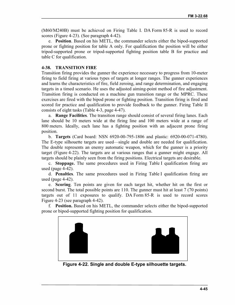
FM 3-22.68
4-45
(M60/M240B) must be achieved on Firing Table I. DA Form 85-R is used to recordscores (Figure 4-23). (See paragraph 4-42).
e. Position. Based on his METL, the commander selects either the bipod-supportedprone or fighting position for table A only. For qualification the position will be eithertripod-supported prone or tripod-supported fighting position table B for practice andtable C for qualification.
4-38. TRANSITION FIRETransition firing provides the gunner the experience necessary to progress from 10-meterfiring to field firing at various types of targets at longer ranges. The gunner experiencesand learns the characteristics of fire, field zeroing, and range determination, and engagingtargets in a timed scenario. He uses the adjusted aiming-point method of fire adjustment.Transition firing is conducted on a machine gun transition range or the MPRC. Theseexercises are fired with the bipod prone or fighting position. Transition firing is fired andscored for practice and qualification to provide feedback to the gunner. Firing Table IIconsists of eight tasks (Table 4-3, page 4-47).
a. Range Facilities. The transition range should consist of several firing lanes. Eachlane should be 10 meters wide at the firing line and 100 meters wide at a range of800 meters. Ideally, each lane has a fighting position with an adjacent prone firingposition.
b. Targets (Card board: NSN 6920-00-795-1806 and plastic: 6920-00-071-4780).The E-type silhouette targets are used—single and double are needed for qualification.The double represents an enemy automatic weapon, which for the gunner is a prioritytarget (Figure 4-22). The targets are at various ranges that a gunner might engage. Alltargets should be plainly seen from the firing positions. Electrical targets are desirable.
c. Stoppage. The same procedures used in Firing Table I qualification firing areused (page 4-42).
d. Penalties. The same procedures used in Firing Table I qualification firing areused (page 4-42).
e. Scoring. Ten points are given for each target hit, whether hit on the first orsecond burst. The total possible points are 110. The gunner must hit at least 7 (70 points)targets out of 11 exposures to qualify. DA Form 85-R is used to record scoresFigure 4-23 (see paragraph 4-42).
f. Position. Based on his METL, the commander selects either the bipod-supportedprone or bipod-supported fighting position for qualification.
Figure 4-22. Single and double E-type silhouette targets.
FM 3-22.68
4-46
4-39. TRANSITION CONDUCT OF FIRE, BIPODThe unit is organized in firing orders based on range constraints. Each firing order shouldconsist of a gunner and an assistant gunner. The assistant gunner assists the gunnerduring prefire checks and zeroing. He also relays signals to the tower operator, checks thegunner's position, and assists him during qualification in target detection and adjustments.The bipod-supported prone or fighting positions are used. The eight tasks are fired in thefollowing manner.
a. Task 1—Field Zero, 500-Meter, Double E-Type Silhouette.(1) The tower operator gives the command MACHINE GUN TO BE MOUNTED
HERE (weapon squad leader’s pointing to the firing points on the transition line),FRONT (weapon squad leader’s pointing to the targets), ACTION.
(2) At the command ACTION the machine gun crew conducts, placing the machinegun into action (bipod mode)
(3) The gunner prepares the rear sight for field zeroing and checks the front sightblade. He sets the range to the zero target on the range scale. The preferred range is500 meters.
(4) The gunner assumes a good position.(5) The tower operator instructs the assistant gunner to prepare a 28-round belt
(M249) or 36-round belt (M60/M240B).(6) When the fire command is given, the gunner and assistant gunner repeat each
element as it is given.FIRE MISSIONFRONTTARGETS: TROOPS IN THE OPENTHREE HUNDREDFIXED, FIVE- TO SEVEN-ROUND BURST (M249) or SEVEN- toNINE-ROUND BURST (M60/M240B)AT MY COMMAND
(7) The gunner loads one 28-round belt of ammunition (M249) or 36-round belt ofammunition (M60/M240B), obtains the proper sight picture, and gives an UP to theassistant gunner.
(8) The assistant gunner relays the READY signal to the tower operator.(9) The tower operator gives the command FIRE.(10) The gunner fires a 5- to 7-round burst (M249) or 7- to 9-round burst
(M60/M240B) at the target when ready.(11) The gunner observes the beaten zone. If the rounds miss the target, he makes
adjustments for windage and elevation.(12) After adjustments have been made, the gunner repeats steps 8 through 9 with the
remaining rounds until rounds are impacting on the target. He records his zero.b. Task 2—400-Meter, Double E-Type Silhouette.(1) The tower operator instructs the gunner to load one 154-round belt.(2) When the fire command is given, the gunner and assistant gunner repeat each
element as it is given. It is only given once for tasks 2 through 8.FIRE MISSIONFRONTTARGET: TROOPS IN THE OPEN
FM 3-22.68
4-47
ONE HUNDRED TO EIGHT HUNDRED METERSFIXED, FIVE- TO SEVEN-ROUND BURST (M249) or SEVEN- TONINE-ROUND BURST (M60/M240B)AT MY COMMAND
(3) The gunner gives an UP to the assistant gunner.(4) The assistant gunner gives the READY signal to the tower operator.(5) The tower operator gives the command FIRE.(6) The gunner scans the sector.(7) A 400-meter, double E-type target is exposed for 10 seconds.(8) The gunner determines the range, places the proper setting on the rear sight,
assumes the proper position, obtains the correct sight alignment and sight picture, andfires a 5- to 7-round burst (M249) or 7- to 9-round burst (M60/M240B).
(9) If the gunner fails to hit the target, he fires another 5- to 7-round burst (M249) or7- to 9-round burst (M60/M240B) using the adjusted aiming point method of fireadjustment.
c. Task 3—500-Meter, Double E-Type Silhouette.(1) The gunner and assistant gunner continues to scan the sector.(2) A 500-meter, double E-type target is exposed for 10 seconds.(3) The gunner determines the range, places the proper setting on the rear sight,
assumes the proper position, obtains the correct sight alignment and sight picture, andfires a 5- to 7-round burst (M249) or 7- to 9-round burst (M60/M240B).
(4) If the gunner fails to hit the target, he fires another 5- to 7-round burst (M249) or7- to 9-round burst (M60/M240B) using the adjusted aiming point method of fireadjustment.
d. Task 4—600-Meter, Single E-Type Silhouette.(1) The gunner and assistant gunner continues to scan the sector.(2) A 600-meter, single E-type target is exposed for 20 seconds.(3) The gunner determines the range, places the proper setting on the rear sight,
assumes the proper position, obtains the correct sight alignment and sight picture, andfires a 5- to 7-round burst (M249) or 7- to 9-round burst (M60/M240B).
(4) If the gunner fails to hit the target, he fires another 5- to 7-round burst (M249) or7- to 9-round burst (M60/M240B) using the adjusted aiming point method of fireadjustment.
e. Task 5—800-Meter, Single E-Type Silhouette.(1) The gunner and assistant gunner continues to scan the sector.(2) A 800-meter, single E-type target is exposed for 30 seconds (total of six targets).(3) The gunner determines the range, places the proper setting on the rear sight,
assumes the proper position, obtains the correct sight alignment and sight picture, andfires a 5- to 7-round burst (M249) or 7- to 9-round burst (M60/M240B).
(4) If the gunner fails to hit the target, he fires another 5- to 7-round burst (M249) or7- to 9-round burst (M60/M240B) using the adjusted aiming point method of fireadjustment.
FM 3-22.68
4-48
f. Task 6—400-Meter, Single E-Type Silhouette; and 600-Meter, Double E-Type Silhouettes.
(1) The gunner and assistant gunner continue to scan the sector.(2) A 400-meter single E-type target and a 600-meter double E-type target are
exposed for 30 seconds.(3) The gunner determines the range, places the proper setting on the rear sight,
assumes the proper position, obtains the correct sight alignment and sight picture, andfires a 5- to 7-round burst (M249) or 7- to 9-round burst (M60/M240B) at each target.
(4) If the gunner fails to hit the target, he fires another 5- to 7-round burst (M249) or7- to 9-round burst (M60/M240B) using the adjusted aiming point method of fireadjustment at each target.
g. Task 7—700-Meter and 800-Meter, Double E-Type Silhouettes.(1) The gunner and assistant gunner continue to scan the sector.(2) A 700-meter and a 800-meter double E-type targets are exposed for 45 seconds
(total of four targets at 700 meters and six targets at 800 meters).(3) The gunner determines the range, places the proper setting on the rear sight,
assumes the proper position, obtains correct sight alignment and sight picture, and fires a5- to 7-round burst (M249) or 7- to 9-round burst (M60/M240B) at each target.
(4) If the gunner fails to hit the target, he fires another 7-round burst using theadjusted aiming point method of fire adjustment at each target.
h. Task 8—400-Meter, Single E-Type Silhouette, and 500-Meter, 600-Meter,Double E-Type Silhouettes.
(1) The gunner and assistant gunner continue to scan the sector.(2) The 400-meter single E-type silhouettes, and 500- and 600-meter double E-type
silhouettes are exposed for 45 seconds (total of two targets at 400 meters, four targets at500 meters, and six targets at 600 meters).
(3) The gunner determines the range, places the proper setting on the rear sight,assumes the proper position, obtains correct sight alignment and sight picture, and fires a5- to 7-round burst (M249) or 7- to 9-round burst (M60/M240B) at each target.
(4) If the gunner fails to hit the target, he fires another 5- to 7-round burst (M249) or7- to 9-round burst (M60/M240B) using the adjusted aiming point method of fireadjustment at each target.

FM 3-22.68
4-49
BIPOD TRANSITION FIREPRONE OR FIGHTING POSITIONPRACTICE AND QUALIFICATION
TASK TIME RDSM249
RDSM60/
M240B
TYPE TARGET RANGE TYPE FIRE
1 No limit 28 36 X 4:1 Double E 500 Fixed, 5- to 7-rdburst (M249) or7- to 9-rd burst(M60/M240B)(field zero)
*2 5seconds
14 18 X 4:1 Double E 400 Fixed, 5- to 7-rdburst (M249) or7- to 9-rd burst(M60/M240B)
*3 10seconds
14 18 X 4:1 Double E 500 Fixed, 5- to 7-rdburst (M249) or7- to 9-rd burst(M60/M240B)
*4 5seconds
14 18 X 4:1 Double E 600 Fixed, 5- to 7-rdburst (M249) or7- to 9-rd burst(M60/M240B)
*5 10seconds
14 18 X 4:1 Double E 800 Fixed, 5- to 7-rdburst (M249) or7- to 9-rd burst(M60/M240B)
*6 20seconds
28 36 X 4:1 Single EDouble E
400600
Fixed, 5- to 7-rdburst (M249) or7- to 9-rd burst(M60/M240B)
*7 20seconds
28 36 X 4:1 Double EDouble E
700800
Fixed, 5- to 7-rdburst (M249) or7- to 9-rd burst(M60/M240B)
*8 25seconds
42 54 X 4:1 Single EDouble EDouble E
400500600
Fixed, 5- to 7-rdburst (M249) or7- to 9-rd burst(M60/M240B)
NOTE: The unit commander determines the firing position. A summary of the ammunitionrequirements is on page 4-53.
*Indicates qualification tasks. X Indicates ball and tracer 4:1 mix.
Table 4-3. Firing Table II—Bipod transition fire.
4-40. TRANSITION FIRE, LIMITED VISIBILITYNight or limited visibility firing requires the soldier to apply the fundamentals of gunnermarksmanship while using nightsights. This training instills confidence in the machinegunner. Each soldier learns how to engage targets using nightsight. He learns to mountthe sight, boresight the weapon at 10-meters, and zero the aided vision devices (IAWAppendix G for that device) at 10-meters using a 10-meter (M16A2) zero target. Finally,he learns to detect and engage a series of undetermined targets at various ranges with the
FM 3-22.68
4-50
aided vision device. Night firing exercises can be conducted during daylight with theAN/PVS-4 when the daylight cover is used. These exercises are for instructional, practiceand qualification purposes. The commander can use this training to assess his unit'sMETL. Night firing is conducted on the same 10-meter range and transition range or amultipurpose machine gun range used for Firing Tables I and II. The tasks and conduct offire in Firing Table III are the same as in Firing Table II. Therefore, a conduct of fire isnot necessary.
a. Time and Ammunition. Table 4-4, Firing Table III (page 4-51) outlinesammunition requirements.
b. Stoppage. The same procedures that are used in Firing Table II, page 4-49.c. Penalties. No penalties are used.d. Scoring. No points are given when the target is hit on the first or second hit, only
a hit or miss. The gunner must hit 6 out of 11 targets in order to be a qualified gunner.The gunner must have qualified on both the 10-meter and transition in order to advanceto this step. DA Form 85-R, provided in the back of this manual, can be used to recordthe number of hits.
e. Conditions. Table 4-3, Firing Table III is used for engaging targets out to400 meters under ideal moonlight or during daylight conditions. If visibility is limitedbecause of a lack of ambient light, commanders may use field-expedient means toidentify targets.
NOTE: The commander may lower the ranges by 100 meters when the ambientconditions do not allow the gunners to engage targets at extended ranges.
f. Targets. Single E-type silhouette targets and double E-type silhouette targets areused.
g. Position. Based on his METL, the commander selects either the bipod-supportedprone position or bipod-supported fighting position.
h. Conduct of Fire. Limited visibility is the same as Firing Table II. The onlydifference is time and distance of the targets to be engaged and firing the scanning,walking and IR discipline exercise.
4-41. AN/PVS-4 ZERORefer to Appendix G and the appropriate TM for this piece of equipment.
CAUTIONWhen mounting the AN/PVS-4 to the mounting bracket, makesure the hole for the screw in the AN/PVS-4 is aligned andflush against the bracket screw. If not, it will strip the threadson the screw, and the AN/PVS-4 cannot be used with theM249 machine gun.
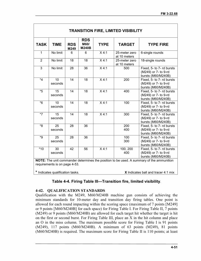
FM 3-22.68
4-51
TRANSITION FIRE, LIMITED VISIBILITY
TASK TIME RDSM249
RDSM60/
M240BTYPE TARGET TYPE FIRE
1 No limit 6 6 X 4:1 25-meter zeroat 10 meters
6-single rounds
2 No limit 18 18 X 4:1 25-meter zeroat 10 meters
18-single rounds
3 No limit 28 36 X 4:1 500 Fixed, 5- to 7- rd bursts(M249) or 7- to 9-rdbursts (M60/M240B)
*4 10seconds
14 18 X 4:1 200 Fixed, 5- to 7- rd bursts(M249) or 7- to 9-rdbursts (M60/M240B)
*5 15seconds
14 18 X 4:1 400 Fixed, 5- to 7- rd bursts(M249) or 7- to 9-rdbursts (M60/M240B)
*6 10seconds
14 18 X 4:1 100 Fixed, 5- to 7- rd bursts(M249) or 7- to 9-rdbursts (M60/M240B)
*7 15seconds
14 18 X 4:1 300 Fixed, 5- to 7- rd bursts(M249) or 7- to 9-rdbursts (M60/M240B)
*8 25seconds
28 36 200400
Fixed, 5- to 7- rd bursts(M249) or 7- to 9-rdbursts (M60/M240B)
*9 25seconds
28 36 100300
Fixed, 5- to 7- rd bursts(M249) or 7- to 9-rdbursts (M60/M240B)
*10 30seconds
42 56 X 4:1 100, 200400
Fixed, 5- to 7- rd bursts(M249) or 7- to 9-rdbursts (M60/M240B)
NOTE: The unit commander determines the position to be used. A summary of the ammunitionrequirements is on page 4-53.
* Indicates qualification tasks. X Indicates ball and tracer 4:1 mix
Table 4-4. Firing Table III—Transition fire, limited visibility.
4-42. QUALIFICATION STANDARDSQualification with the M249, M60/M240B machine gun consists of achieving theminimum standards for 10-meter day and transition day firing tables. One point isallowed for each round impacting within the scoring space (maximum of 7 points [M249]or 9 points [M60/M240B] for each space) for Firing Table I. For Firing Table II, 7 points(M249) or 9 points (M60/M240B) are allowed for each target hit whether the target is hiton the first or second burst. For Firing Table III, place an X in the hit column and placean O in the miss column. The maximum possible score for Firing Table I is 91 points(M249), 117 points (M60/M240B). A minimum of 63 points (M249), 81 points(M60/M240B) is required. The maximum score for Firing Table II is 110 points; at least
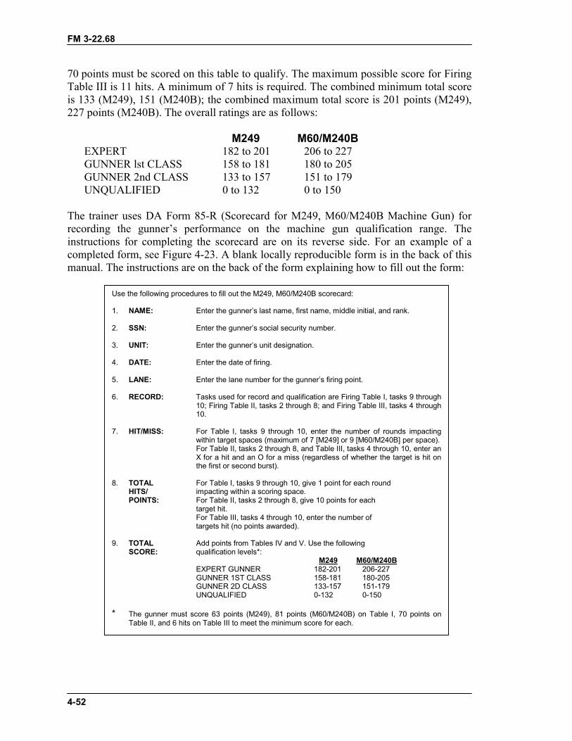
FM 3-22.68
4-52
70 points must be scored on this table to qualify. The maximum possible score for FiringTable III is 11 hits. A minimum of 7 hits is required. The combined minimum total scoreis 133 (M249), 151 (M240B); the combined maximum total score is 201 points (M249),227 points (M240B). The overall ratings are as follows:
M249 M60/M240BEXPERT 182 to 201 206 to 227GUNNER lst CLASS 158 to 181 180 to 205GUNNER 2nd CLASS 133 to 157 151 to 179UNQUALIFIED 0 to 132 0 to 150
The trainer uses DA Form 85-R (Scorecard for M249, M60/M240B Machine Gun) forrecording the gunner’s performance on the machine gun qualification range. Theinstructions for completing the scorecard are on its reverse side. For an example of acompleted form, see Figure 4-23. A blank locally reproducible form is in the back of thismanual. The instructions are on the back of the form explaining how to fill out the form:
Use the following procedures to fill out the M249, M60/M240B scorecard:
1. NAME: Enter the gunner’s last name, first name, middle initial, and rank.
2. SSN: Enter the gunner’s social security number.
3. UNIT: Enter the gunner’s unit designation.
4. DATE: Enter the date of firing.
5. LANE: Enter the lane number for the gunner’s firing point.
6. RECORD: Tasks used for record and qualification are Firing Table I, tasks 9 through10; Firing Table II, tasks 2 through 8; and Firing Table III, tasks 4 through10.
7. HIT/MISS: For Table I, tasks 9 through 10, enter the number of rounds impactingwithin target spaces (maximum of 7 [M249] or 9 [M60/M240B] per space).For Table II, tasks 2 through 8, and Table III, tasks 4 through 10, enter anX for a hit and an O for a miss (regardless of whether the target is hit onthe first or second burst).
8. TOTAL For Table I, tasks 9 through 10, give 1 point for each roundHITS/ impacting within a scoring space.POINTS: For Table II, tasks 2 through 8, give 10 points for each
target hit.For Table III, tasks 4 through 10, enter the number oftargets hit (no points awarded).
9. TOTAL Add points from Tables IV and V. Use the followingSCORE: qualification levels*:
M249 M60/M240BEXPERT GUNNER 182-201 206-227GUNNER 1ST CLASS 158-181 180-205GUNNER 2D CLASS 133-157 151-179UNQUALIFIED 0-132 0-150
* The gunner must score 63 points (M249), 81 points (M60/M240B) on Table I, 70 points onTable II, and 6 hits on Table III to meet the minimum score for each.

FM 3-22.68
4-53
The following is a summary of ammunition required:
M249 M60/M240B TYPETable I, Practice 185 231 BallTable I, Record 91 117 X4:1Table II, Practice 182 236 X4:1Table II, Record 154 200 X4:1Table III, Practice 360 460 X4:1Table III, Record 154 200 X4:1
NOTE: See DA Pam 350-38 for STRAC ammunition requirements.

FM 3-22.68
4-54
Figure 4-23. Example of a completed DA Form 85-R.
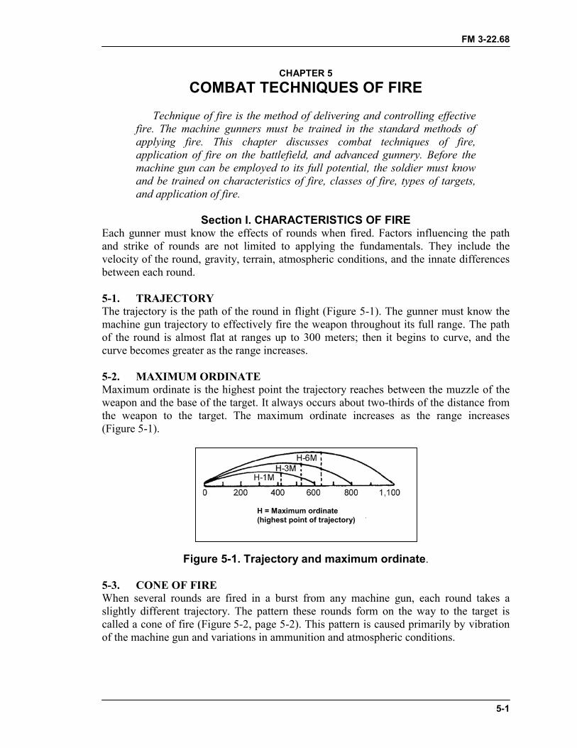
FM 3-22.68
5-1
CHAPTER 5COMBAT TECHNIQUES OF FIRE
Technique of fire is the method of delivering and controlling effectivefire. The machine gunners must be trained in the standard methods ofapplying fire. This chapter discusses combat techniques of fire,application of fire on the battlefield, and advanced gunnery. Before themachine gun can be employed to its full potential, the soldier must knowand be trained on characteristics of fire, classes of fire, types of targets,and application of fire.
Section I. CHARACTERISTICS OF FIREEach gunner must know the effects of rounds when fired. Factors influencing the pathand strike of rounds are not limited to applying the fundamentals. They include thevelocity of the round, gravity, terrain, atmospheric conditions, and the innate differencesbetween each round.
5-1. TRAJECTORYThe trajectory is the path of the round in flight (Figure 5-1). The gunner must know themachine gun trajectory to effectively fire the weapon throughout its full range. The pathof the round is almost flat at ranges up to 300 meters; then it begins to curve, and thecurve becomes greater as the range increases.
5-2. MAXIMUM ORDINATEMaximum ordinate is the highest point the trajectory reaches between the muzzle of theweapon and the base of the target. It always occurs about two-thirds of the distance fromthe weapon to the target. The maximum ordinate increases as the range increases(Figure 5-1).
Figure 5-1. Trajectory and maximum ordinate.
5-3. CONE OF FIREWhen several rounds are fired in a burst from any machine gun, each round takes aslightly different trajectory. The pattern these rounds form on the way to the target iscalled a cone of fire (Figure 5-2, page 5-2). This pattern is caused primarily by vibrationof the machine gun and variations in ammunition and atmospheric conditions.
H = Maximum ordinate(highest point of trajectory)
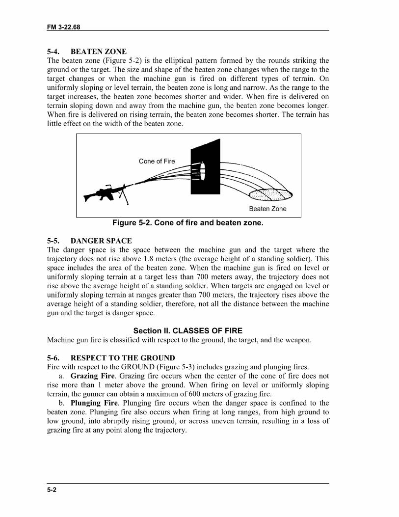
FM 3-22.68
5-2
5-4. BEATEN ZONEThe beaten zone (Figure 5-2) is the elliptical pattern formed by the rounds striking theground or the target. The size and shape of the beaten zone changes when the range to thetarget changes or when the machine gun is fired on different types of terrain. Onuniformly sloping or level terrain, the beaten zone is long and narrow. As the range to thetarget increases, the beaten zone becomes shorter and wider. When fire is delivered onterrain sloping down and away from the machine gun, the beaten zone becomes longer.When fire is delivered on rising terrain, the beaten zone becomes shorter. The terrain haslittle effect on the width of the beaten zone.
Figure 5-2. Cone of fire and beaten zone.
5-5. DANGER SPACEThe danger space is the space between the machine gun and the target where thetrajectory does not rise above 1.8 meters (the average height of a standing soldier). Thisspace includes the area of the beaten zone. When the machine gun is fired on level oruniformly sloping terrain at a target less than 700 meters away, the trajectory does notrise above the average height of a standing soldier. When targets are engaged on level oruniformly sloping terrain at ranges greater than 700 meters, the trajectory rises above theaverage height of a standing soldier, therefore, not all the distance between the machinegun and the target is danger space.
Section II. CLASSES OF FIREMachine gun fire is classified with respect to the ground, the target, and the weapon.
5-6. RESPECT TO THE GROUNDFire with respect to the GROUND (Figure 5-3) includes grazing and plunging fires.
a. Grazing Fire. Grazing fire occurs when the center of the cone of fire does notrise more than 1 meter above the ground. When firing on level or uniformly slopingterrain, the gunner can obtain a maximum of 600 meters of grazing fire.
b. Plunging Fire. Plunging fire occurs when the danger space is confined to thebeaten zone. Plunging fire also occurs when firing at long ranges, from high ground tolow ground, into abruptly rising ground, or across uneven terrain, resulting in a loss ofgrazing fire at any point along the trajectory.
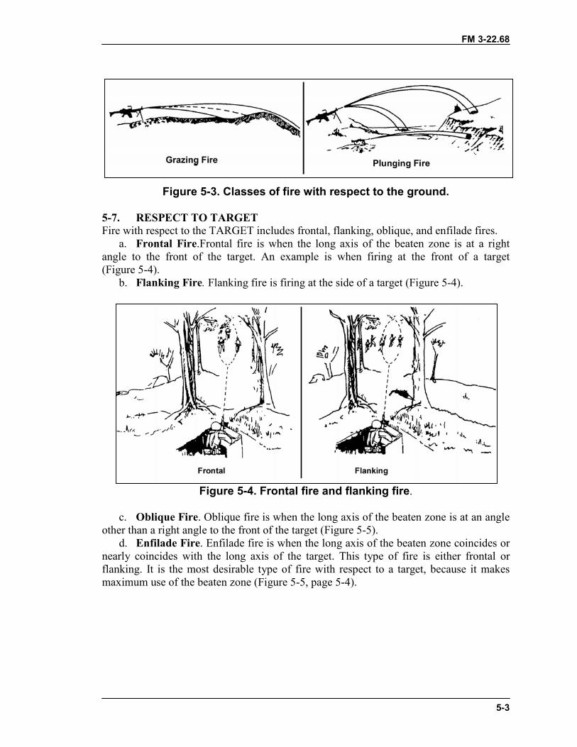
FM 3-22.68
5-3
Figure 5-3. Classes of fire with respect to the ground.
5-7. RESPECT TO TARGETFire with respect to the TARGET includes frontal, flanking, oblique, and enfilade fires.
a. Frontal Fire.Frontal fire is when the long axis of the beaten zone is at a rightangle to the front of the target. An example is when firing at the front of a target(Figure 5-4).
b. Flanking Fire. Flanking fire is firing at the side of a target (Figure 5-4).
Figure 5-4. Frontal fire and flanking fire.
c. Oblique Fire. Oblique fire is when the long axis of the beaten zone is at an angleother than a right angle to the front of the target (Figure 5-5).
d. Enfilade Fire. Enfilade fire is when the long axis of the beaten zone coincides ornearly coincides with the long axis of the target. This type of fire is either frontal orflanking. It is the most desirable type of fire with respect to a target, because it makesmaximum use of the beaten zone (Figure 5-5, page 5-4).
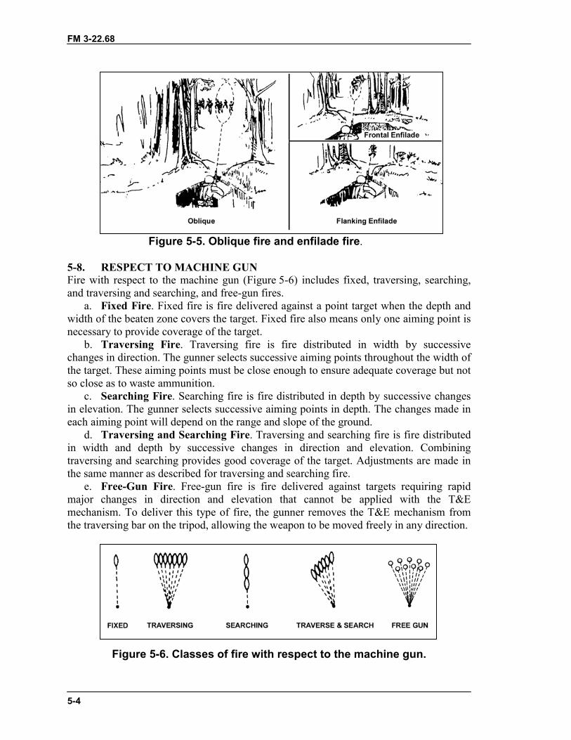
FM 3-22.68
5-4
Figure 5-5. Oblique fire and enfilade fire.
5-8. RESPECT TO MACHINE GUNFire with respect to the machine gun (Figure 5-6) includes fixed, traversing, searching,and traversing and searching, and free-gun fires.
a. Fixed Fire. Fixed fire is fire delivered against a point target when the depth andwidth of the beaten zone covers the target. Fixed fire also means only one aiming point isnecessary to provide coverage of the target.
b. Traversing Fire. Traversing fire is fire distributed in width by successivechanges in direction. The gunner selects successive aiming points throughout the width ofthe target. These aiming points must be close enough to ensure adequate coverage but notso close as to waste ammunition.
c. Searching Fire. Searching fire is fire distributed in depth by successive changesin elevation. The gunner selects successive aiming points in depth. The changes made ineach aiming point will depend on the range and slope of the ground.
d. Traversing and Searching Fire. Traversing and searching fire is fire distributedin width and depth by successive changes in direction and elevation. Combiningtraversing and searching provides good coverage of the target. Adjustments are made inthe same manner as described for traversing and searching fire.
e. Free-Gun Fire. Free-gun fire is fire delivered against targets requiring rapidmajor changes in direction and elevation that cannot be applied with the T&Emechanism. To deliver this type of fire, the gunner removes the T&E mechanism fromthe traversing bar on the tripod, allowing the weapon to be moved freely in any direction.
Figure 5-6. Classes of fire with respect to the machine gun.
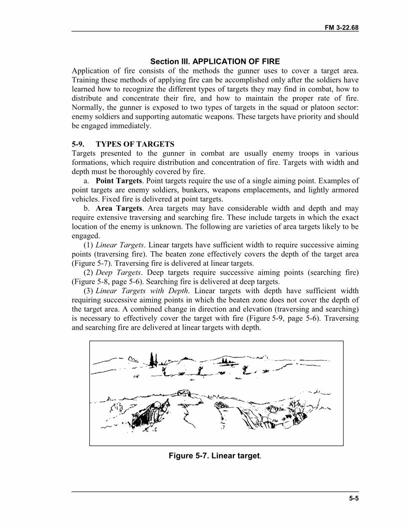
FM 3-22.68
5-5
Section III. APPLICATION OF FIREApplication of fire consists of the methods the gunner uses to cover a target area.Training these methods of applying fire can be accomplished only after the soldiers havelearned how to recognize the different types of targets they may find in combat, how todistribute and concentrate their fire, and how to maintain the proper rate of fire.Normally, the gunner is exposed to two types of targets in the squad or platoon sector:enemy soldiers and supporting automatic weapons. These targets have priority and shouldbe engaged immediately.
5-9. TYPES OF TARGETSTargets presented to the gunner in combat are usually enemy troops in variousformations, which require distribution and concentration of fire. Targets with width anddepth must be thoroughly covered by fire.
a. Point Targets. Point targets require the use of a single aiming point. Examples ofpoint targets are enemy soldiers, bunkers, weapons emplacements, and lightly armoredvehicles. Fixed fire is delivered at point targets.
b. Area Targets. Area targets may have considerable width and depth and mayrequire extensive traversing and searching fire. These include targets in which the exactlocation of the enemy is unknown. The following are varieties of area targets likely to beengaged.
(1) Linear Targets. Linear targets have sufficient width to require successive aimingpoints (traversing fire). The beaten zone effectively covers the depth of the target area(Figure 5-7). Traversing fire is delivered at linear targets.
(2) Deep Targets. Deep targets require successive aiming points (searching fire)(Figure 5-8, page 5-6). Searching fire is delivered at deep targets.
(3) Linear Targets with Depth. Linear targets with depth have sufficient widthrequiring successive aiming points in which the beaten zone does not cover the depth ofthe target area. A combined change in direction and elevation (traversing and searching)is necessary to effectively cover the target with fire (Figure 5-9, page 5-6). Traversingand searching fire are delivered at linear targets with depth.
Figure 5-7. Linear target.
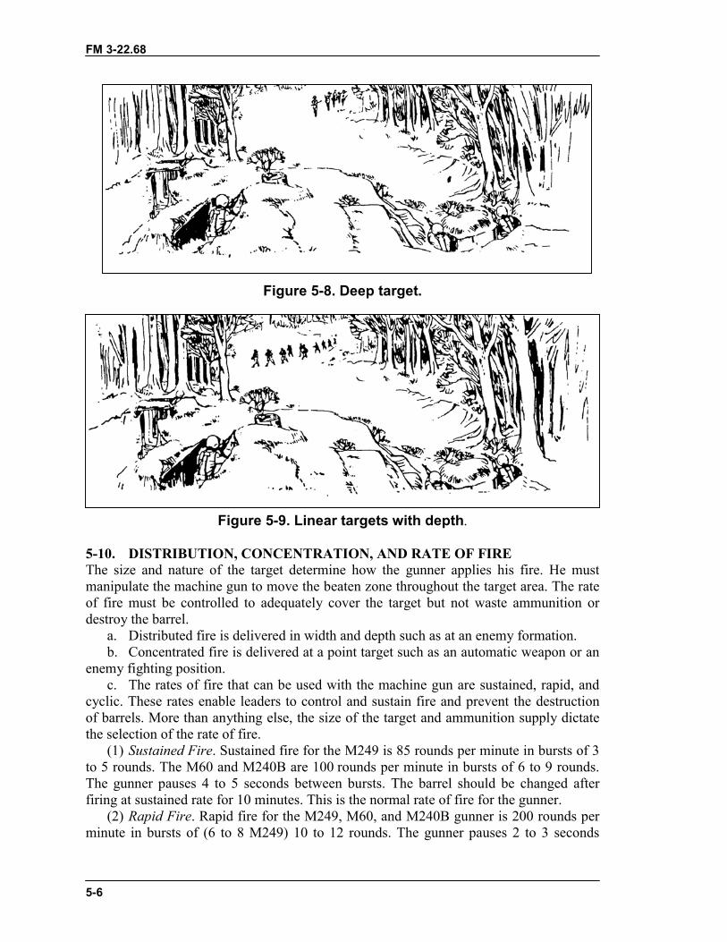
FM 3-22.68
5-6
Figure 5-8. Deep target.
Figure 5-9. Linear targets with depth.
5-10. DISTRIBUTION, CONCENTRATION, AND RATE OF FIREThe size and nature of the target determine how the gunner applies his fire. He mustmanipulate the machine gun to move the beaten zone throughout the target area. The rateof fire must be controlled to adequately cover the target but not waste ammunition ordestroy the barrel.
a. Distributed fire is delivered in width and depth such as at an enemy formation.b. Concentrated fire is delivered at a point target such as an automatic weapon or an
enemy fighting position.c. The rates of fire that can be used with the machine gun are sustained, rapid, and
cyclic. These rates enable leaders to control and sustain fire and prevent the destructionof barrels. More than anything else, the size of the target and ammunition supply dictatethe selection of the rate of fire.
(1) Sustained Fire. Sustained fire for the M249 is 85 rounds per minute in bursts of 3to 5 rounds. The M60 and M240B are 100 rounds per minute in bursts of 6 to 9 rounds.The gunner pauses 4 to 5 seconds between bursts. The barrel should be changed afterfiring at sustained rate for 10 minutes. This is the normal rate of fire for the gunner.
(2) Rapid Fire. Rapid fire for the M249, M60, and M240B gunner is 200 rounds perminute in bursts of (6 to 8 M249) 10 to 12 rounds. The gunner pauses 2 to 3 seconds
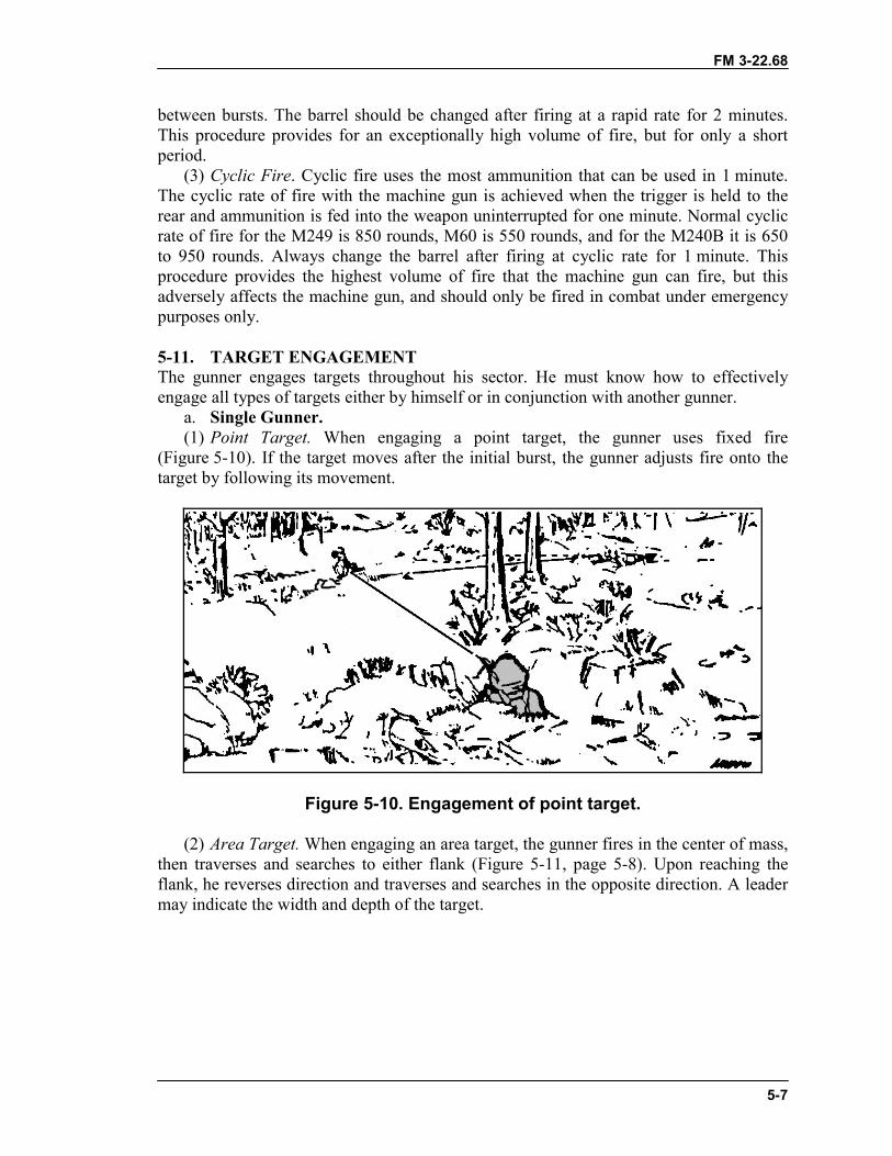
FM 3-22.68
5-7
between bursts. The barrel should be changed after firing at a rapid rate for 2 minutes.This procedure provides for an exceptionally high volume of fire, but for only a shortperiod.
(3) Cyclic Fire. Cyclic fire uses the most ammunition that can be used in 1 minute.The cyclic rate of fire with the machine gun is achieved when the trigger is held to therear and ammunition is fed into the weapon uninterrupted for one minute. Normal cyclicrate of fire for the M249 is 850 rounds, M60 is 550 rounds, and for the M240B it is 650to 950 rounds. Always change the barrel after firing at cyclic rate for 1 minute. Thisprocedure provides the highest volume of fire that the machine gun can fire, but thisadversely affects the machine gun, and should only be fired in combat under emergencypurposes only.
5-11. TARGET ENGAGEMENTThe gunner engages targets throughout his sector. He must know how to effectivelyengage all types of targets either by himself or in conjunction with another gunner.
a. Single Gunner.(1) Point Target. When engaging a point target, the gunner uses fixed fire
(Figure 5-10). If the target moves after the initial burst, the gunner adjusts fire onto thetarget by following its movement.
Figure 5-10. Engagement of point target.
(2) Area Target. When engaging an area target, the gunner fires in the center of mass,then traverses and searches to either flank (Figure 5-11, page 5-8). Upon reaching theflank, he reverses direction and traverses and searches in the opposite direction. A leadermay indicate the width and depth of the target.
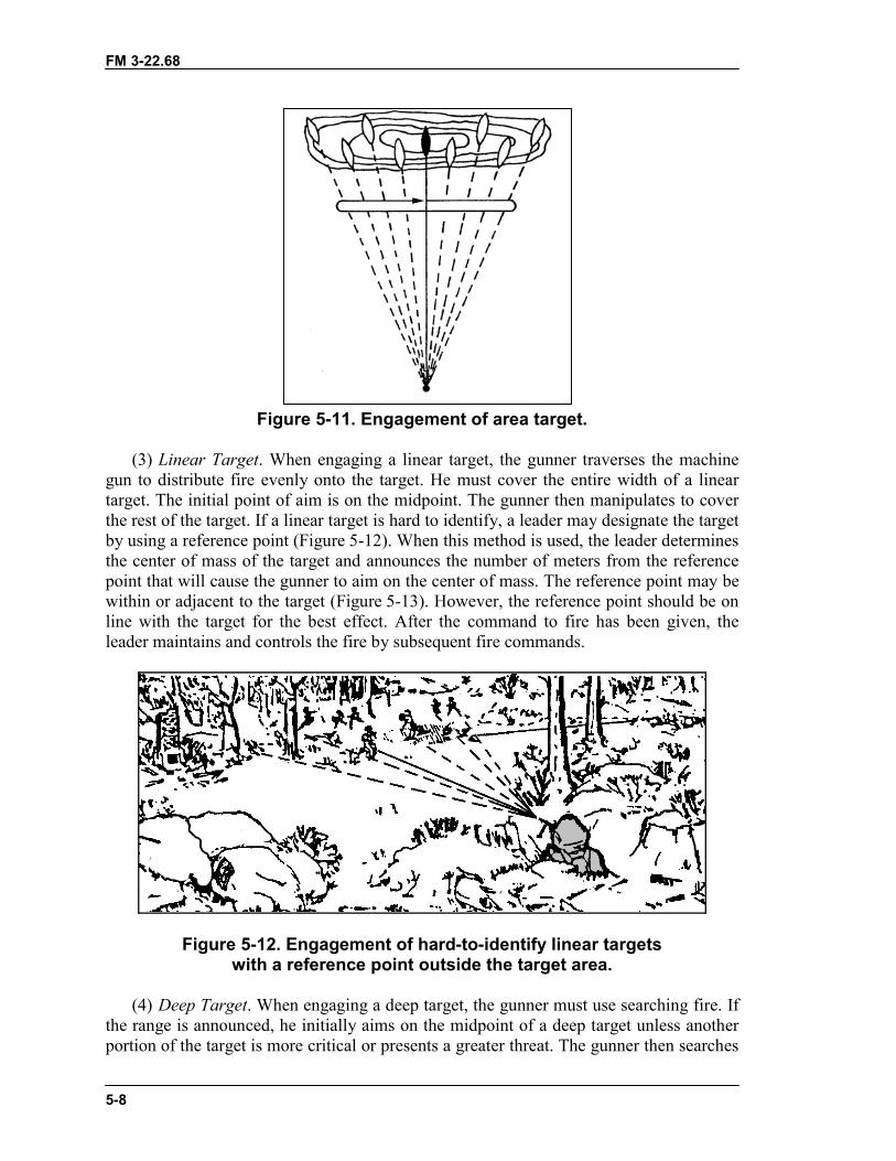
FM 3-22.68
5-8
Figure 5-11. Engagement of area target.
(3) Linear Target. When engaging a linear target, the gunner traverses the machinegun to distribute fire evenly onto the target. He must cover the entire width of a lineartarget. The initial point of aim is on the midpoint. The gunner then manipulates to coverthe rest of the target. If a linear target is hard to identify, a leader may designate the targetby using a reference point (Figure 5-12). When this method is used, the leader determinesthe center of mass of the target and announces the number of meters from the referencepoint that will cause the gunner to aim on the center of mass. The reference point may bewithin or adjacent to the target (Figure 5-13). However, the reference point should be online with the target for the best effect. After the command to fire has been given, theleader maintains and controls the fire by subsequent fire commands.
Figure 5-12. Engagement of hard-to-identify linear targetswith a reference point outside the target area.
(4) Deep Target. When engaging a deep target, the gunner must use searching fire. Ifthe range is announced, he initially aims on the midpoint of a deep target unless anotherportion of the target is more critical or presents a greater threat. The gunner then searches
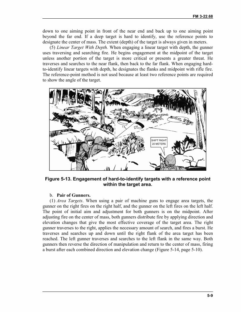
FM 3-22.68
5-9
down to one aiming point in front of the near end and back up to one aiming pointbeyond the far end. If a deep target is hard to identify, use the reference points todesignate the center of mass. The extent (depth) of the target is always given in meters.
(5) Linear Target With Depth. When engaging a linear target with depth, the gunneruses traversing and searching fire. He begins engagement at the midpoint of the targetunless another portion of the target is more critical or presents a greater threat. Hetraverses and searches to the near flank, then back to the far flank. When engaging hard-to-identify linear targets with depth, he designates the flanks and midpoint with rifle fire.The reference-point method is not used because at least two reference points are requiredto show the angle of the target.
Figure 5-13. Engagement of hard-to-identify targets with a reference pointwithin the target area.
b. Pair of Gunners.(1) Area Targets. When using a pair of machine guns to engage area targets, the
gunner on the right fires on the right half, and the gunner on the left fires on the left half.The point of initial aim and adjustment for both gunners is on the midpoint. Afteradjusting fire on the center of mass, both gunners distribute fire by applying direction andelevation changes that give the most effective coverage of the target area. The rightgunner traverses to the right, applies the necessary amount of search, and fires a burst. Hetraverses and searches up and down until the right flank of the area target has beenreached. The left gunner traverses and searches to the left flank in the same way. Bothgunners then reverse the direction of manipulation and return to the center of mass, firinga burst after each combined direction and elevation change (Figure 5-14, page 5-10).
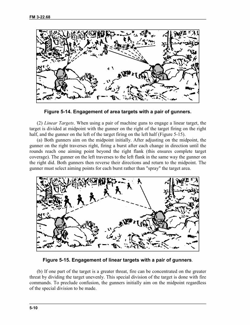
FM 3-22.68
5-10
Figure 5-14. Engagement of area targets with a pair of gunners.
(2) Linear Targets. When using a pair of machine guns to engage a linear target, thetarget is divided at midpoint with the gunner on the right of the target firing on the righthalf, and the gunner on the left of the target firing on the left half (Figure 5-15).
(a) Both gunners aim on the midpoint initially. After adjusting on the midpoint, thegunner on the right traverses right, firing a burst after each change in direction until therounds reach one aiming point beyond the right flank (this ensures complete targetcoverage). The gunner on the left traverses to the left flank in the same way the gunner onthe right did. Both gunners then reverse their directions and return to the midpoint. Thegunner must select aiming points for each burst rather than "spray" the target area.
Figure 5-15. Engagement of linear targets with a pair of gunners.
(b) If one part of the target is a greater threat, fire can be concentrated on the greaterthreat by dividing the target unevenly. This special division of the target is done with firecommands. To preclude confusion, the gunners initially aim on the midpoint regardlessof the special division to be made.
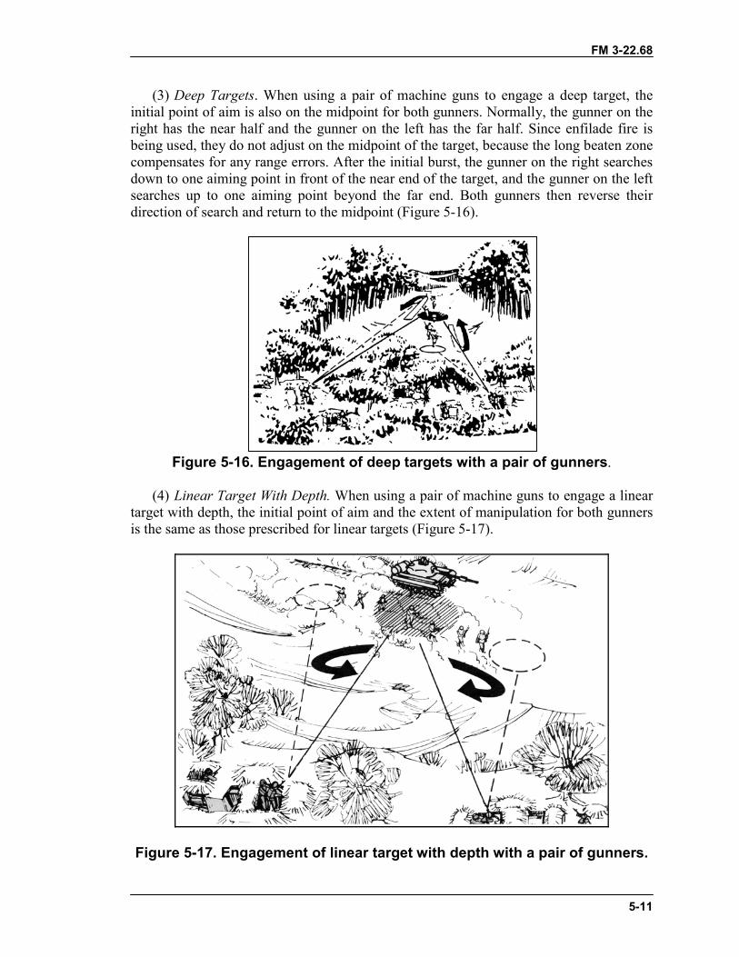
FM 3-22.68
5-11
(3) Deep Targets. When using a pair of machine guns to engage a deep target, theinitial point of aim is also on the midpoint for both gunners. Normally, the gunner on theright has the near half and the gunner on the left has the far half. Since enfilade fire isbeing used, they do not adjust on the midpoint of the target, because the long beaten zonecompensates for any range errors. After the initial burst, the gunner on the right searchesdown to one aiming point in front of the near end of the target, and the gunner on the leftsearches up to one aiming point beyond the far end. Both gunners then reverse theirdirection of search and return to the midpoint (Figure 5-16).
Figure 5-16. Engagement of deep targets with a pair of gunners.
(4) Linear Target With Depth. When using a pair of machine guns to engage a lineartarget with depth, the initial point of aim and the extent of manipulation for both gunnersis the same as those prescribed for linear targets (Figure 5-17).
Figure 5-17. Engagement of linear target with depth with a pair of gunners.
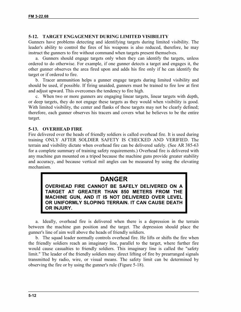
FM 3-22.68
5-12
5-12. TARGET ENGAGEMENT DURING LIMITED VISIBILITYGunners have problems detecting and identifying targets during limited visibility. Theleader's ability to control the fires of his weapons is also reduced, therefore, he mayinstruct the gunners to fire without command when targets present themselves.
a. Gunners should engage targets only when they can identify the targets, unlessordered to do otherwise. For example, if one gunner detects a target and engages it, theother gunner observes the area fired upon and adds his fire only if he can identify thetarget or if ordered to fire.
b. Tracer ammunition helps a gunner engage targets during limited visibility andshould be used, if possible. If firing unaided, gunners must be trained to fire low at firstand adjust upward. This overcomes the tendency to fire high.
c. When two or more gunners are engaging linear targets, linear targets with depth,or deep targets, they do not engage these targets as they would when visibility is good.With limited visibility, the center and flanks of these targets may not be clearly defined;therefore, each gunner observes his tracers and covers what he believes to be the entiretarget.
5-13. OVERHEAD FIREFire delivered over the heads of friendly soldiers is called overhead fire. It is used duringtraining ONLY AFTER SOLDIER SAFETY IS CHECKED AND VERIFIED. Theterrain and visibility dictate when overhead fire can be delivered safely. (See AR 385-63for a complete summary of training safety requirements.) Overhead fire is delivered withany machine gun mounted on a tripod because the machine guns provide greater stabilityand accuracy, and because vertical mil angles can be measured by using the elevatingmechanism.
a. Ideally, overhead fire is delivered when there is a depression in the terrainbetween the machine gun position and the target. The depression should place thegunner's line of aim well above the heads of friendly soldiers.
b. The squad leader normally controls overhead fire. He lifts or shifts the fire whenthe friendly soldiers reach an imaginary line, parallel to the target, where further firewould cause casualties to friendly soldiers. This imaginary line is called the "safetylimit." The leader of the friendly soldiers may direct lifting of fire by prearranged signalstransmitted by radio, wire, or visual means. The safety limit can be determined byobserving the fire or by using the gunner's rule (Figure 5-18).
DANGEROVERHEAD FIRE CANNOT BE SAFELY DELIVERED ON ATARGET AT GREATER THAN 850 METERS FROM THEMACHINE GUN, AND IT IS NOT DELIVERED OVER LEVELOR UNIFORMLY SLOPING TERRAIN. IT CAN CAUSE DEATHOR INJURY.
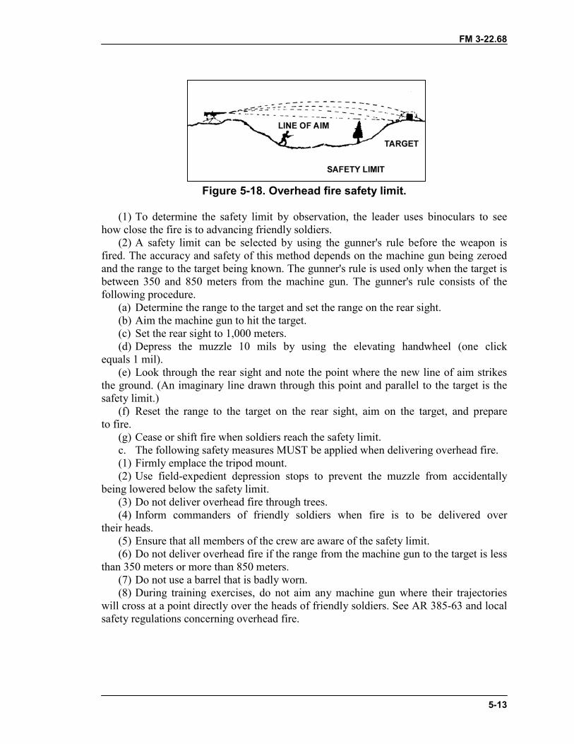
FM 3-22.68
5-13
Figure 5-18. Overhead fire safety limit.
(1) To determine the safety limit by observation, the leader uses binoculars to seehow close the fire is to advancing friendly soldiers.
(2) A safety limit can be selected by using the gunner's rule before the weapon isfired. The accuracy and safety of this method depends on the machine gun being zeroedand the range to the target being known. The gunner's rule is used only when the target isbetween 350 and 850 meters from the machine gun. The gunner's rule consists of thefollowing procedure.
(a) Determine the range to the target and set the range on the rear sight.(b) Aim the machine gun to hit the target.(c) Set the rear sight to 1,000 meters.(d) Depress the muzzle 10 mils by using the elevating handwheel (one click
equals 1 mil).(e) Look through the rear sight and note the point where the new line of aim strikes
the ground. (An imaginary line drawn through this point and parallel to the target is thesafety limit.)
(f) Reset the range to the target on the rear sight, aim on the target, and prepareto fire.
(g) Cease or shift fire when soldiers reach the safety limit.c. The following safety measures MUST be applied when delivering overhead fire.(1) Firmly emplace the tripod mount.(2) Use field-expedient depression stops to prevent the muzzle from accidentally
being lowered below the safety limit.(3) Do not deliver overhead fire through trees.(4) Inform commanders of friendly soldiers when fire is to be delivered over
their heads.(5) Ensure that all members of the crew are aware of the safety limit.(6) Do not deliver overhead fire if the range from the machine gun to the target is less
than 350 meters or more than 850 meters.(7) Do not use a barrel that is badly worn.(8) During training exercises, do not aim any machine gun where their trajectories
will cross at a point directly over the heads of friendly soldiers. See AR 385-63 and localsafety regulations concerning overhead fire.
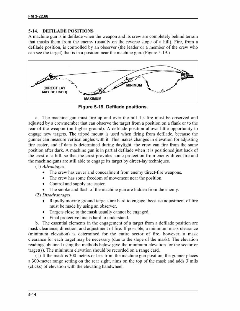
FM 3-22.68
5-14
5-14. DEFILADE POSITIONSA machine gun is in defilade when the weapon and its crew are completely behind terrainthat masks them from the enemy (usually on the reverse slope of a hill). Fire, from adefilade position, is controlled by an observer (the leader or a member of the crew whocan see the target) that is in a position near the machine gun. (Figure 5-19.)
Figure 5-19. Defilade positions.
a. The machine gun must fire up and over the hill. Its fire must be observed andadjusted by a crewmember that can observe the target from a position on a flank or to therear of the weapon (on higher ground). A defilade position allows little opportunity toengage new targets. The tripod mount is used when firing from defilade, because thegunner can measure vertical angles with it. This makes changes in elevation for adjustingfire easier, and if data is determined during daylight, the crew can fire from the sameposition after dark. A machine gun is in partial defilade when it is positioned just back ofthe crest of a hill, so that the crest provides some protection from enemy direct-fire andthe machine guns are still able to engage its target by direct-lay techniques.
(1) Advantages.� The crew has cover and concealment from enemy direct-fire weapons.� The crew has some freedom of movement near the position.� Control and supply are easier.� The smoke and flash of the machine gun are hidden from the enemy.
(2) Disadvantages.� Rapidly moving ground targets are hard to engage, because adjustment of fire
must be made by using an observer.� Targets close to the mask usually cannot be engaged.� Final protective line is hard to understand.
b. The essential elements in the engagement of a target from a defilade position aremask clearance, direction, and adjustment of fire. If possible, a minimum mask clearance(minimum elevation) is determined for the entire sector of fire, however, a maskclearance for each target may be necessary (due to the slope of the mask). The elevationreadings obtained using the methods below give the minimum elevation for the sector ortarget(s). The minimum elevation should be recorded on a range card.
(1) If the mask is 300 meters or less from the machine gun position, the gunner placesa 300-meter range setting on the rear sight, aims on the top of the mask and adds 3 mils(clicks) of elevation with the elevating handwheel.
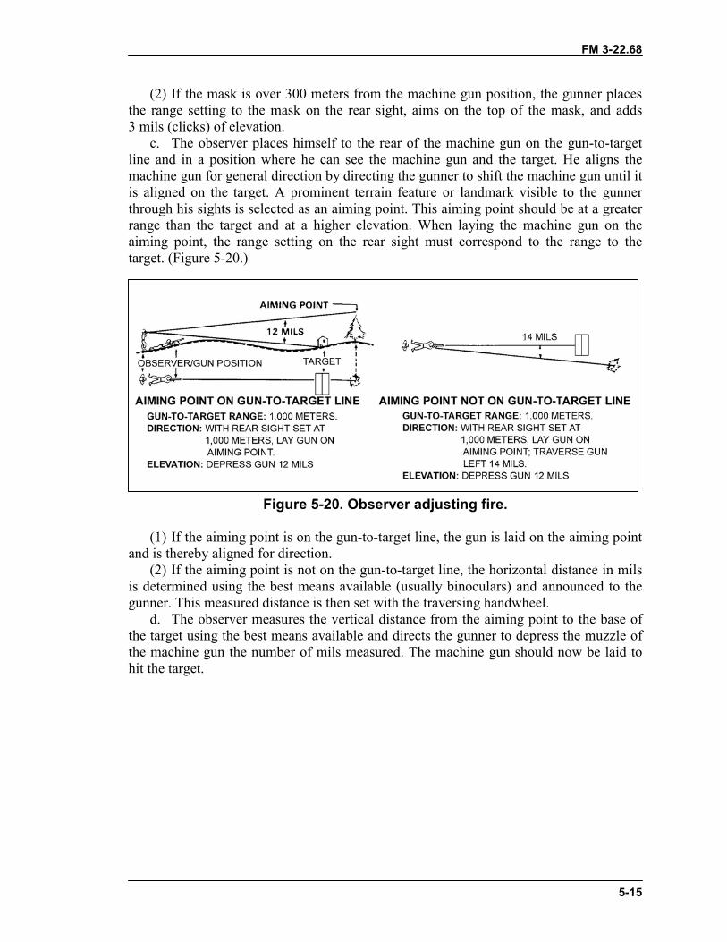
FM 3-22.68
5-15
(2) If the mask is over 300 meters from the machine gun position, the gunner placesthe range setting to the mask on the rear sight, aims on the top of the mask, and adds3 mils (clicks) of elevation.
c. The observer places himself to the rear of the machine gun on the gun-to-targetline and in a position where he can see the machine gun and the target. He aligns themachine gun for general direction by directing the gunner to shift the machine gun until itis aligned on the target. A prominent terrain feature or landmark visible to the gunnerthrough his sights is selected as an aiming point. This aiming point should be at a greaterrange than the target and at a higher elevation. When laying the machine gun on theaiming point, the range setting on the rear sight must correspond to the range to thetarget. (Figure 5-20.)
Figure 5-20. Observer adjusting fire.
(1) If the aiming point is on the gun-to-target line, the gun is laid on the aiming pointand is thereby aligned for direction.
(2) If the aiming point is not on the gun-to-target line, the horizontal distance in milsis determined using the best means available (usually binoculars) and announced to thegunner. This measured distance is then set with the traversing handwheel.
d. The observer measures the vertical distance from the aiming point to the base ofthe target using the best means available and directs the gunner to depress the muzzle ofthe machine gun the number of mils measured. The machine gun should now be laid tohit the target.
FM 3-22.68
5-16
Section IV. PREDETERMINED FIRESPredetermined fires organize the battlefield for the gunners. They allow the leader andgunner to select potential targets or target areas that will most likely be engaged or thathave tactical significance. This includes dismounted enemy avenues of approach, likelypositions for automatic weapons, and probable enemy assault positions. The gunners dothis by using sectors of fire, final protective lines, or a principal direction of fire andselected target areas. This preparation maximizes the effectiveness of the machine gunduring good as well as limited visibility. It enhances fire control by reducing the timerequired to identify targets, determine range, and manipulate the weapon onto the target.Abbreviated fire commands and previously recorded data enable the gunner to aim oradjust fire on the target quickly and accurately. Selected targets should be fired on indaylight whenever practical to confirm data. The range card identifies the targets andprovides a record of firing data.
5-15. TERMINOLOGYSeveral terms are associated with predetermined fire that every gunner needs to know.
a. Sector of Fire. A sector of fire is an area to be covered by fire that is assigned toan individual, a weapon, or a unit. Gunners are normally assigned a primary and asecondary sector of fire.
b. Final Protective Fire. An FPF is an immediately available prearranged barrier offire to stop enemy movement across defensive lines or areas.
c. Final Protective Line. An FPL is a predetermined line along which grazing fireis placed to stop an enemy assault. If an FPL is assigned, the machine gun is sightedalong it except when other targets are being engaged. An FPL becomes the machine gun'spart of the unit's final protective fires. An FPL is fixed in direction and elevation;however, a small shift for search must be employed to prevent the enemy from crawlingunder the FPL and to compensate for irregularities in the terrain or the sinking of thetripod legs into soft soil during firing. Fire must be delivered during all conditions ofvisibility.
d. Principal Direction of Fire. A PDF is a direction of fire assigned priority tocover an area that has good fields of fire or has a likely dismounted avenue of approach.It also provides mutual support to an adjacent unit. Machine guns are sighted using thePDF if an FPL has not been assigned. If a PDF is assigned and other targets are not beingengaged, machine guns remain on the PDF. A PDF has the following characteristics.
(1) It is used only if an FPL is not assigned; it then becomes the machine gun's part ofthe unit's final protective fires.
(2) When the target has width, direction is determined by aiming on one edge of thetarget area and noting the amount of traverse necessary to cover the entire target.
(3) The gunner is responsible for the entire wedge-shaped area from the muzzle of theweapon to the target, but elevation may be fixed for a priority portion of the target.
e. Grazing Fire. A good FPL covers the maximum area with grazing fire. Grazingfire can be obtained over various types of terrain out to a maximum of 600 meters. Toobtain the maximum extent of grazing fire over level or uniformly sloping terrain, thegunner sets the rear sight at 600 meters. He then selects a point on the ground that heestimates to be 600 meters from the machine gun, and he aims, fires, and adjusts on thatpoint. To prevent enemy soldiers from crawling under grazing fire, he searches
FM 3-22.68
5-17
(downward) by lowering the muzzle of the weapon. To do this, the gunner separateshis elbows.
f. Dead Space. The extent of grazing fire and the extent of dead space may bedetermined in two ways. In the preferred method, the machine gun is adjusted forelevation and direction. A member of the squad then walks along the FPL while thegunner aims through the sights. In places where the soldier's waist (midsection) fallsbelow the gunner's point of aim, dead space exists. Arm-and-hand signals must be used tocontrol the soldier who is walking and to obtain an accurate account of the dead spaceand its location. Another method is to observe the flight of tracer ammunition from aposition behind and to the flank of the weapon.
g. Fire Control. Predetermined targets, including the FPL or PDF, are engaged onorder or by SOP. The signal for calling for these fires is normally stated in the defenseorder. Control these predetermined targets by using arm-and-hand signals, voicecommands, or pyrotechnic devices. Gunners fire the FPL or PDF at the sustained rate offire unless the situation calls for a higher rate. When engaging other predeterminedtargets, the sustained rate of fire is also used unless a different rate is ordered.
h. Primary Sector of Fire. The primary sector of fire is the area to be covered by anindividual or unit.
i. Secondary Sector of Fire. The secondary sector of fire is the same area coveredby the same individual or unit after it has moved to a different location.
5-16. RANGE CARDThe standard range card (DA Form 5517-R) provides a record of firing data and aidsdefensive fire planning. (See FM 7-8 for a reproducible copy of this form.) Its useenhances fire control and rapid engagement of predetermined targets. It is also used inestimating ranges to other targets within the sector of fire. Each gunner makes twocopies—one for his position and one for the squad leader. The squad leader uses his copyto prepare his sector sketch. The range card is prepared immediately upon occupation andis constantly revised. Each range card contains the following:
� Weapon symbol (Figure 5-21, page 5-18).� Sector of fire.� PDF or FPL.� Range, azimuth, and number label to predetermined targets.� Dead space.� Distance and azimuth from a known point or eight-digit grid coordinate
(reference point).� Magnetic north arrow.� Data section.
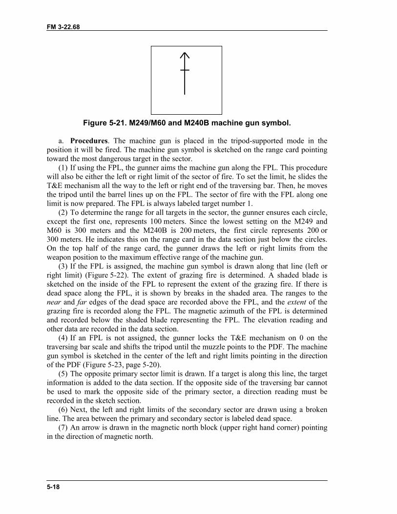
FM 3-22.68
5-18
Figure 5-21. M249/M60 and M240B machine gun symbol.
a. Procedures. The machine gun is placed in the tripod-supported mode in theposition it will be fired. The machine gun symbol is sketched on the range card pointingtoward the most dangerous target in the sector.
(1) If using the FPL, the gunner aims the machine gun along the FPL. This procedurewill also be either the left or right limit of the sector of fire. To set the limit, he slides theT&E mechanism all the way to the left or right end of the traversing bar. Then, he movesthe tripod until the barrel lines up on the FPL. The sector of fire with the FPL along onelimit is now prepared. The FPL is always labeled target number 1.
(2) To determine the range for all targets in the sector, the gunner ensures each circle,except the first one, represents 100 meters. Since the lowest setting on the M249 andM60 is 300 meters and the M240B is 200 meters, the first circle represents 200 or300 meters. He indicates this on the range card in the data section just below the circles.On the top half of the range card, the gunner draws the left or right limits from theweapon position to the maximum effective range of the machine gun.
(3) If the FPL is assigned, the machine gun symbol is drawn along that line (left orright limit) (Figure 5-22). The extent of grazing fire is determined. A shaded blade issketched on the inside of the FPL to represent the extent of the grazing fire. If there isdead space along the FPL, it is shown by breaks in the shaded area. The ranges to thenear and far edges of the dead space are recorded above the FPL, and the extent of thegrazing fire is recorded along the FPL. The magnetic azimuth of the FPL is determinedand recorded below the shaded blade representing the FPL. The elevation reading andother data are recorded in the data section.
(4) If an FPL is not assigned, the gunner locks the T&E mechanism on 0 on thetraversing bar scale and shifts the tripod until the muzzle points to the PDF. The machinegun symbol is sketched in the center of the left and right limits pointing in the directionof the PDF (Figure 5-23, page 5-20).
(5) The opposite primary sector limit is drawn. If a target is along this line, the targetinformation is added to the data section. If the opposite side of the traversing bar cannotbe used to mark the opposite side of the primary sector, a direction reading must berecorded in the sketch section.
(6) Next, the left and right limits of the secondary sector are drawn using a brokenline. The area between the primary and secondary sector is labeled dead space.
(7) An arrow is drawn in the magnetic north block (upper right hand corner) pointingin the direction of magnetic north.
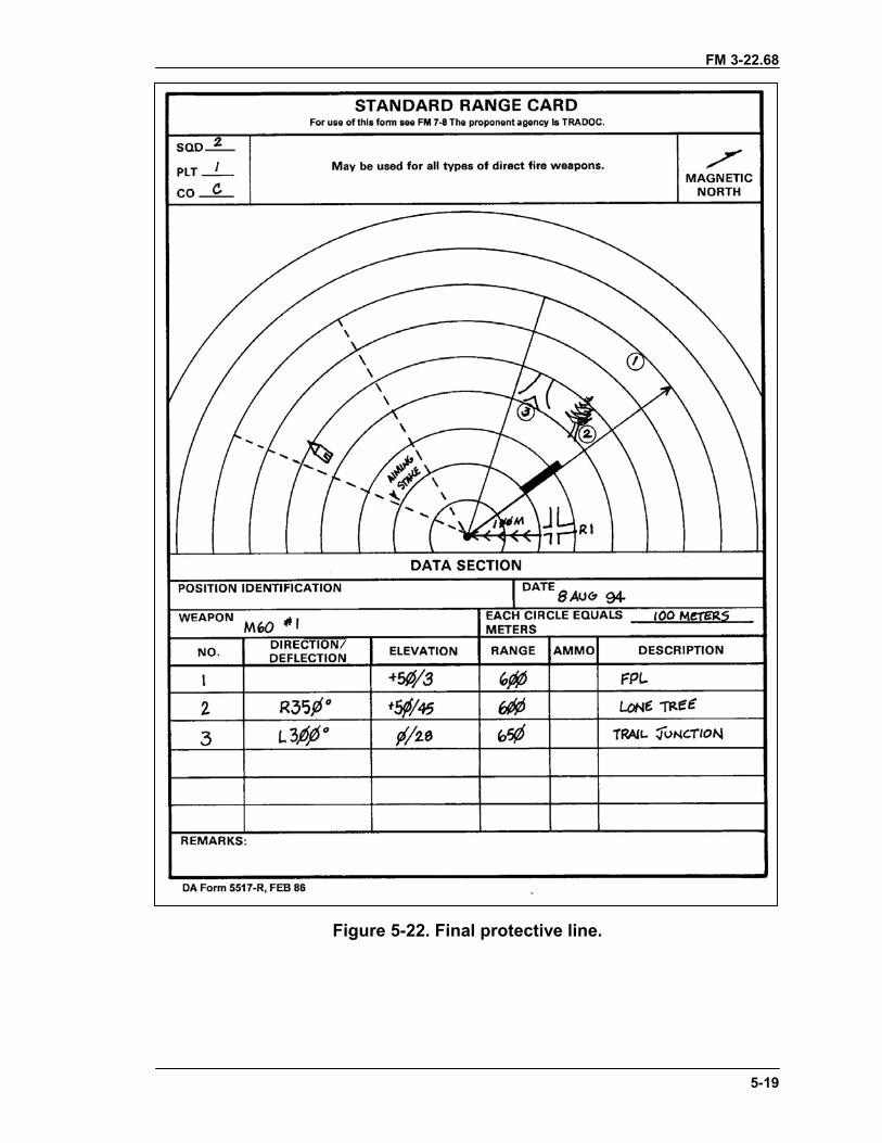
FM 3-22.68
5-19
Figure 5-22. Final protective line.
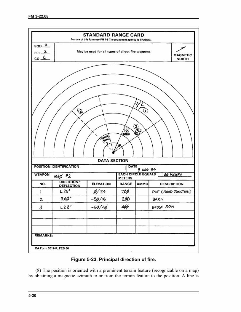
FM 3-22.68
5-20
Figure 5-23. Principal direction of fire.
(8) The position is oriented with a prominent terrain feature (recognizable on a map)by obtaining a magnetic azimuth to or from the terrain feature to the position. A line is
FM 3-22.68
5-21
drawn between these two points. Arrow barbs are drawn along this line pointing in thedirection the magnetic azimuth was taken. The magnetic azimuth is recorded in mils ordegrees below the line. If a prominent terrain feature is not available, identify the positionby using an eight-digit grid coordinate. The grid coordinate is recorded below theposition on the range card.
(9) The gunner's number, unit designation (SQD, PLT, CO), and date are recorded inthe upper left-hand corner. For security, do not use a unit designation higherthan a company.
(10) Targets within the sector are identified. A symbol is drawn to represent the targetin the appropriate place within the sector of fire. Targets in the primary sector are shownby numbers and enclosed in circles. An FPL, when assigned, is always labeled targetNumber 1. Other targets are assigned subsequent numbers in order of tactical importance.
(a) Wide targets in the primary sector are usually engaged in the center; however, theinitial burst can be positioned anywhere the leader designates. The gunner measures thetarget width and records it in the data section; for example, TW-20 (target width is20 mils). The gunner lays on the point on the target where the initial burst will be placed,and traverses to one edge of the target, while counting the clicks. He records the numberof clicks he traverses and the direction he moves the muzzle; for example, TW-20/R7(target width, 20 mils; right 7 clicks). After the initial burst, the gunner traverses 7 clicksto the right edge of the target and back to the left 20 clicks to cover the target area. To layon the left edge of the target, the gunner records TW-20/R20.
(b) When field expedients are used with the machine gun to engage targets, they aresketched above the drawing of the target. Predetermined targets in the secondary sectorare sketched on the range card and ranges to these targets are recorded below the targetsbut not in the data section. Field expedients should be used for targets in thesecondary sector.
b. Field Expedients. When laying the machine gun for predetermined targets, thegunner can use field expedients as a means of engaging targets when other sources arenot available. These methods are not as effective as the traversing bar and T&Emechanism method.
(1) Base Stake Technique. A base stake is used to define sector limits and mayprovide the lay for the FPL or predetermined targets along a primary or secondary sectorlimit. This technique is effective in all visibility conditions. The gunner uses thefollowing steps:
(a) Defines the sector limits by laying the gun for direction along one sector limit andby emplacing a stake along the outer edge of the folded bipod legs. Rotates the legsslightly on the receiver, so that the gunner takes up the “play”. Uses the same procedurefor placing a stake along the opposite sector limit.
(b) Lays the machine gun along the FPL by moving the muzzle of the machine gun toa sector limit. Adjusts for elevation by driving a stake into the ground, so that the top ofthe stake is under the gas cylinder extension, allowing a few mils of depression to coverirregularities in the terrain.
(c) Lays the machine gun to engage other targets within a sector limit, in a primarysector by using the procedure described previously, except keeps the elevation fixed.
(2) Notched-Stake or Tree-Crotch Technique. The gunner uses the notched-stake ortree-crotch technique (Figure 5-24, page 5-22) with the bipod mount to engage
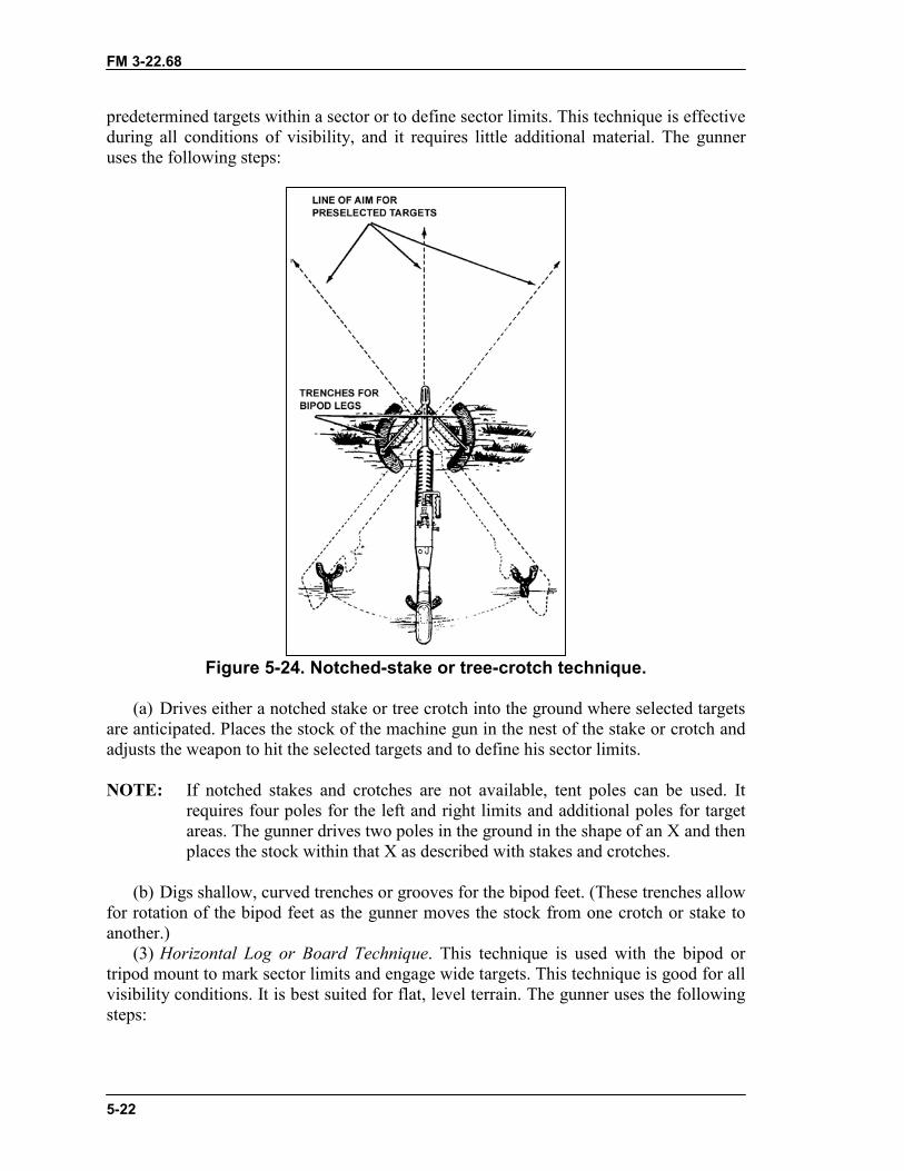
FM 3-22.68
5-22
predetermined targets within a sector or to define sector limits. This technique is effectiveduring all conditions of visibility, and it requires little additional material. The gunneruses the following steps:
Figure 5-24. Notched-stake or tree-crotch technique.
(a) Drives either a notched stake or tree crotch into the ground where selected targetsare anticipated. Places the stock of the machine gun in the nest of the stake or crotch andadjusts the weapon to hit the selected targets and to define his sector limits.
NOTE: If notched stakes and crotches are not available, tent poles can be used. Itrequires four poles for the left and right limits and additional poles for targetareas. The gunner drives two poles in the ground in the shape of an X and thenplaces the stock within that X as described with stakes and crotches.
(b) Digs shallow, curved trenches or grooves for the bipod feet. (These trenches allowfor rotation of the bipod feet as the gunner moves the stock from one crotch or stake toanother.)
(3) Horizontal Log or Board Technique. This technique is used with the bipod ortripod mount to mark sector limits and engage wide targets. This technique is good for allvisibility conditions. It is best suited for flat, level terrain. The gunner uses the followingsteps:
FM 3-22.68
5-23
(a) Using a bipod-mounted machine gun, places a log or board beneath the stock ofthe weapon, so that the stock can slide across it freely. Digs shallow, curved trenches orgrooves for the bipod feet to allow rotation of the feet as he moves the stock along the logor board. (The gunner may mark the sector limits by notching or placing stops on the logor board. The gunner uses the bipod firing position and grip.)
(b) Using a tripod-mounted machine gun, places a log or board beneath the barrel,positioning it so that the barrel, when resting on the log or board is at the proper elevationto obtain grazing fire. Marks the sector limits, when appropriate, as described for thebipod in the preceding paragraph. (This technique is used only if a T&E mechanism isnot available.)
Section V. FIRE CONTROLFire control includes all actions of the leader and soldiers in planning, preparing, andapplying fire on a target. The leader selects and designates targets. He also designates themidpoint and flanks or ends of a target, unless they are obvious to the gunner. The gunnerfires at the instant desired. He then adjusts fire, regulates the rate of fire, shifts from onetarget to another, and ceases fire. When firing, the gunner should continue to fire until thetarget is neutralized or until signaled to do otherwise by the leader.
5-17. METHODS OF FIRE CONTROLThe noise and confusion of battle may limit the use of some of these methods; therefore,the leader must select a method or combination of methods that will accomplish themission.
a. Oral. This can be an effective method of control, but sometimes the leader maybe too far away from the gunner, or the noise of the battle may make it impossible forhim to hear. The primary means of the oral fire control method is the issuance of a firecommand.
b. Arm-and-Hand Signals. This is an effective method when the gunner can see theleader. All gunners must know the standard arm-and-hand signals. The leader gets thegunner's attention and then points to the target. When the gunner returns the READYsignal, the leader commands FIRE.
c. Prearranged Signals. These are either visual or sound signals such as casualty-producing devices, pyrotechnics, whistle blasts, or tracers. These signals should beincluded in SOPs. If the leader wants to shift fire at a certain time, he gives a prearrangedsignal such as smoke or pyrotechnics. Upon seeing the signal, the gunner shifts his fire toa prearranged point.
d. Personal Contact. In many situations, the leader must issue orders directly toindividual soldiers and is used more than any other method by small-unit leaders. Theleader must use maximum cover and concealment to keep from disclosing the position orhimself.
e. Range Cards. When using this method of fire control, the leader must ensure allrange cards are current and accurate. Once this is accomplished, the leader may designatecertain targets for certain weapons with the use of limiting stakes or with fire commands.He should also designate no-fire zones or restricted fire areas to others. The key factor, inthis method of fire control, is that gunners must be well-disciplined and pay attention todetail.
FM 3-22.68
5-24
f. Standing Operating Procedures. SOPs are actions to be executed withoutcommand that are developed during the training of the squads. Their use eliminates manycommands and simplifies the leader's fire control. SOPs for certain actions andcommands can be developed to make gunners more effective. Some examples follow:
(1) Observation. The gunners continuously observe their sectors.(2) Fire. Gunners open fire without command on appropriate targets that appear
within their sectors.(3) Check. While firing, the gunners periodically check with the leader for
instructions.(4) Return Fire. The gunners return enemy fire without order, concentrating on
enemy automatic weapons.(5) Shift Fire. Gunners shift their fires without command when more dangerous
targets appear.(6) Rate of Fire. When gunners engage a target, they initially fire at the rate necessary
to gain and maintain fire superiority.(7) Mutual Support. When two or more gunners are engaging the same target and one
stops firing, the other increases the rate of fire and covers the entire target. When onlyone gunner is required to engage a target and the leader has alerted two or more, thegunner not firing aims on the target and follows the movements of the target. This is sothat he can fire instantly should the other machine gun malfunction or cease fire beforethe target has been eliminated.
5-18. FIRE COMMANDSA fire command is given to deliver effective fire on a target quickly and withoutconfusion. When the leader decides to engage a target that is not obvious to the squad, hemust provide them with the information they need to effectively engage the target. Hemust alert the soldiers; give a target direction, description, and range; name the method offire; and give the command to fire. There are initial fire commands and subsequent firecommands.
a. Initial Fire Commands. Initial fire commands are given to adjust onto the target,change the rate of fire after a fire mission is in progress, interrupt fire, or terminate thealert.
b. Elements. Fire commands for all direct-fire weapons follow a pattern thatincludes similar elements. There are six elements in the fire command for the machinegun: alert, direction, description, range, method of fire, and command to open fire. Thegunners repeat each element of fire command as it is given.
(1) Alert. This element prepares the gunners for further instructions. The leader mayalert both gunners in the squad and may have only one fire, depending upon the situation.To alert and have both gunners fire, the leader announces, "Fire mission." If he desires toalert both gunners but have only one fire, he announces,"Gun number one, fire mission."In all cases, upon receiving the alert, the gunners load their machine guns and place themon FIRE.
(2) Direction. This element indicates the general direction to the target and may begiven in one or a combination of the following methods.
(a) Orally. The leader orally gives the direction to the target in relation to the positionof the gunner (for example, FRONT, LEFT FRONT, RIGHT FRONT).
FM 3-22.68
5-25
(b) Pointing. The leader designates a small or obscure target by pointing with hisfinger or aiming with a weapon. When he points with his finger, a soldier standing behindhim should be able to look over his shoulder and sight along his arm and index finger tolocate the target. When aiming his weapon at a target, a soldier looking through the sightsshould be able to see the target.
(c) Tracer Ammunition. Tracer ammunition is a quick and sure method ofdesignating a target that is not clearly visible. When using this method, the leader shouldfirst give the general direction to direct the gunner's attention to the target area. Toprevent the loss of surprise when using tracer ammunition, the leader does not fire untilhe has given all elements of the fire command except the command to fire. The leadermay fire his individual weapon. The firing of the tracer(s) then becomes the last elementof the fire command, and it is the signal to open fire.
NOTE: Soldiers must be aware that with the night vision device, temporary blindness"white out" may occur when firing tracer ammunition at night or whenexposed to other external light sources. Lens covers may reduce this effect.
EXAMPLEFIRE MISSIONFRONTFIVE HUNDREDWATCH MY TRACER(S)
(d) Reference Points. Another way to designate obscure targets is to use easy-to-recognize reference points. All leaders and gunners must know terrain features and theterminology used to describe them (FM 21-26). When using a reference point, the word"reference" precedes its description. This is done to avoid confusion. The generaldirection to the reference point should be given.
EXAMPLEFIRE MISSIONFRONTREFERENCE: BUNKER, CENTER MASSTARGET: TROOPS EXTENDING SHORT ONE HUNDRED, OVER
ONE HUNDREDFOUR HUNDREDFIRE
(Sometimes the reference point may be outside the target area).
FM 3-22.68
5-26
EXAMPLEFIRE MISSIONFRONTREFERENCE: BUNKER, RIGHT FOUR FINGERS, CENTER MASSTARGET: TROOPS EXTENDING SHORT ONE HUNDRED, OVER
ONE HUNDREDTHREE HUNDREDSEARCHAT MY COMMANDFIRE
(Sometimes a target must be designated by using successive reference points).
EXAMPLEGUN NUMBER ONE, FIRE MISSIONRIGHT FRONTREFERENCE: RED-ROOFED HOUSE, LEFT TO HAYSTACK, LEFT TO
BARN
(Finger measurements can be used to direct the gunner's attention to the right or left ofreference points).
EXAMPLEFIRE MISSIONLEFT FRONTREFERENCE: CROSSROADS, RIGHT FOUR FINGERS
(3) Description. The target description creates a picture of the target in the minds ofthe gunners. To properly apply their fire, the soldiers must know the type of target theyare to engage. The leader should describe it briefly. If the target is obvious, no descriptionis necessary.
(4) Range. The leader always announces the estimated range to the target. The rangeis given, so the gunner knows how far to look for the target and what range setting to puton the rear sight. Range is announced in meters; however, since the meter is the standardunit of range measurement, the word "meters" is not used. With machine gun's, the rangeis determined and announced to the nearest hundred or thousand (in other words, THREEHUNDRED, or ONE THOUSAND).
EXAMPLEFIRE MISSIONFRONTREFERENCE: KNOCKED-OUT TANK, LEFT TWO FINGERSTARGET: TROOPSTHREE HUNDRED
(5) Method of Fire. This element includes manipulation and rate of fire.Manipulation prescribes the class of fire with respect to the weapon. It is announced as
FM 3-22.68
5-27
FIXED, TRAVERSE, SEARCH, or TRAVERSE AND SEARCH. Rate controls thevolume of fire (sustained, rapid, and cyclic). Normally, the gunner uses the sustained rateof fire. The rate of fire is omitted from the fire command. The method of fire for themachine gun is usually 3- to 5-round bursts (M249) and 6- to 9-round bursts(M60/M240B).
EXAMPLEFIRE MISSIONFRONTREFERENCE: KNOCKED-OUT TANK, LEFT TWO FINGERSTARGET: TROOPSTHREE HUNDREDTRAVERSE
(6) Command to Open Fire. When fire is to be withheld so that surprise fire can bedelivered on a target or to ensure that both gunners open fire at the same time, the leadermay preface the command to commence firing with AT MY COMMAND or AT MYSIGNAL. When the gunners are ready to engage the target, they report READY to theleader. The leader then gives the command FIRE at the specific time desired.
EXAMPLEFIRE MISSIONFRONTTROOPSFOUR HUNDREDAT MY COMMAND or AT MY SIGNAL (The leader pauses until the
gunners are ready and fire is desired.)FIRE (The gunners fire on prearranged signal.)
If immediate fire is required, the command FIRE is given without pause and the gunnersfire as soon as they are ready.
c. Subsequent Fire Commands. These fire commands are used to makeadjustments in direction and elevation, to change rates of fire after a fire mission is inprogress, to interrupt fires, or to terminate the alert. If the gunner fails to properly engagea target, the leader must promptly correct him by announcing or signaling the desiredchanges. When these changes are given, the gunner makes the corrections and resumesfiring without further command.
(1) Adjustments in direction and elevation with the machine gun are always given inmeters; one finger is used to indicate 1 meter and so on. Adjustment for direction is givenfirst. For example: RIGHT ONE ZERO METERS or LEFT FIVE METERS. Adjustmentfor elevation is given next. For example: ADD FIVE METERS or DROPONE FIVE METERS. These changes may be given orally or with arm-and-hand signals.
(2) Changes in the rate of fire are given orally or by arm-and-hand signals.(3) To interrupt firing, the leader announces "Cease fire," or he signals to cease fire.
The gunners remain on the alert. They resume firing when given the command FIRE.(4) To terminate the alert, the leader announces "Cease fire, end of mission."
FM 3-22.68
5-28
d. Doubtful Elements and Corrections. When the gunner is in doubt about anyelement of the fire command, he replies "Say again range, target." The leader thenannounces "The command was," repeats the element in question, and continues with thefire command.
(1) When the leader makes an error in the initial fire command, he corrects it byannouncing "Correction," and then gives the corrected element.
EXAMPLEFIRE MISSIONFRONTTROOPSSIX HUNDREDCORRECTIONTHREE HUNDREDTRAVERSEAT MY COMMAND
(2) When the leader makes an error in the subsequent fire command, he may correctit by announcing "Correction," and then repeating the entire subsequent fire command.
EXAMPLELEFT FIVE METERS, DROP ONE METERCORRECTIONLEFT FIVE METERS, DROP ONE HUNDRED METERS
e. Abbreviated Fire Commands. Fire commands need not be complete to beeffective. In combat, the leader gives only the elements necessary to place fire on a targetquickly and without confusion. During training, however, he should use all of theelements to get gunners in the habit of thinking and reacting properly when a target is tobe engaged. After the gunner's initial training in fire commands, he should be taught toreact to abbreviated fire commands, using one of the following methods.
(1) Oral. The leader may want to place the fire of one machine gun on an enemymachine gun.
EXAMPLEGUN NUMBER ONE, FIRE MISSIONMACHINE GUNFOUR HUNDREDFIRE
(2) Arm-and-Hand Signals. Battlefield noise and the distance between the gunner andthe leader often make it necessary to use arm-and-hand signals to control fire(Figure 5-25). When an action or movement is to be executed by only one of the gunners,a preliminary signal is given to that gunner only. The following are commonly usedsignals for fire control.
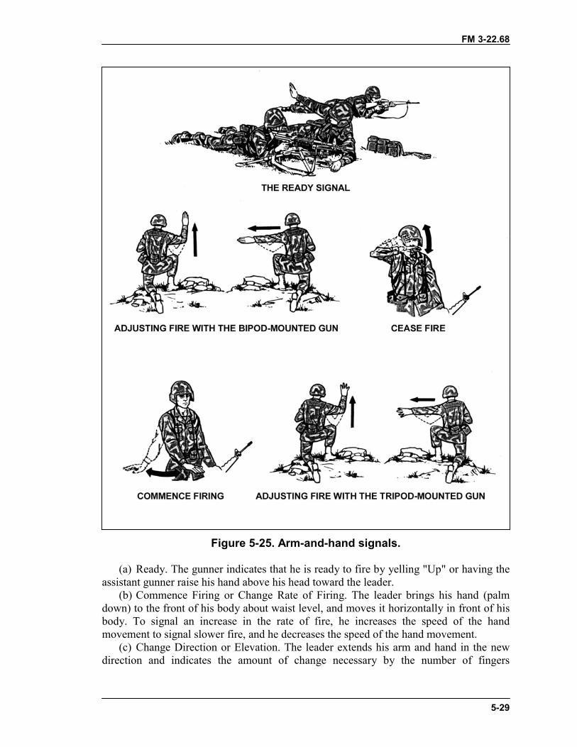
FM 3-22.68
5-29
Figure 5-25. Arm-and-hand signals.
(a) Ready. The gunner indicates that he is ready to fire by yelling "Up" or having theassistant gunner raise his hand above his head toward the leader.
(b) Commence Firing or Change Rate of Firing. The leader brings his hand (palmdown) to the front of his body about waist level, and moves it horizontally in front of hisbody. To signal an increase in the rate of fire, he increases the speed of the handmovement to signal slower fire, and he decreases the speed of the hand movement.
(c) Change Direction or Elevation. The leader extends his arm and hand in the newdirection and indicates the amount of change necessary by the number of fingers
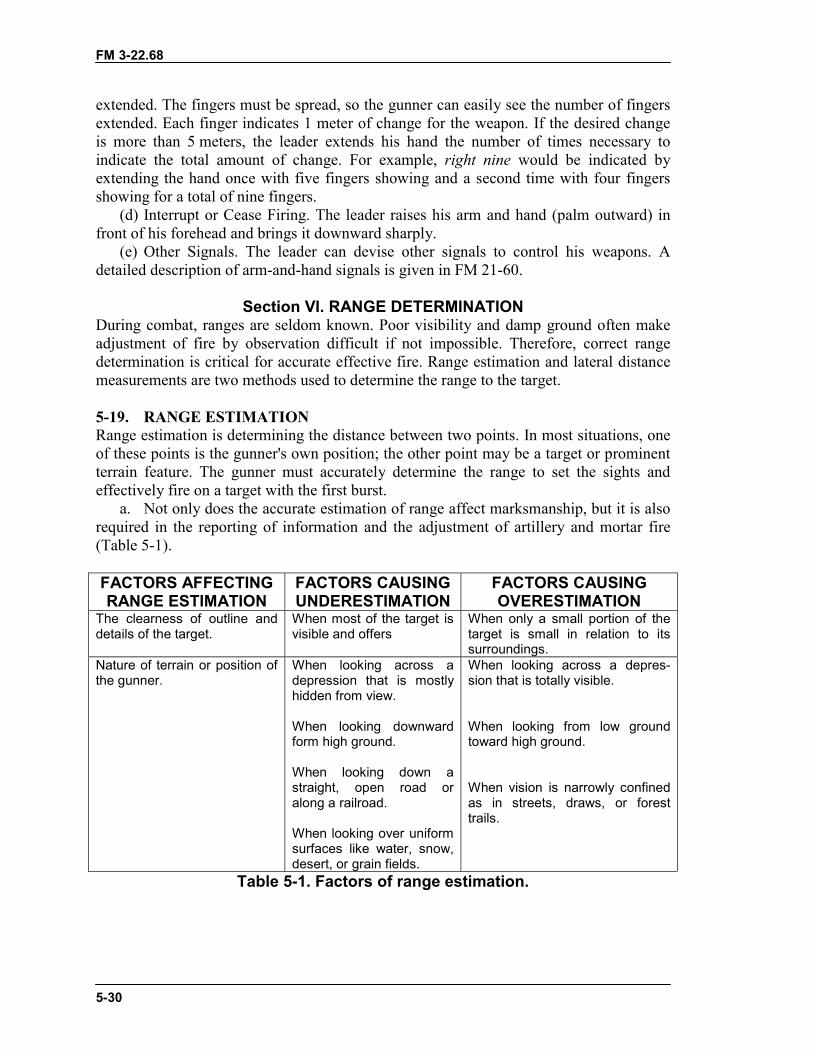
FM 3-22.68
5-30
extended. The fingers must be spread, so the gunner can easily see the number of fingersextended. Each finger indicates 1 meter of change for the weapon. If the desired changeis more than 5 meters, the leader extends his hand the number of times necessary toindicate the total amount of change. For example, right nine would be indicated byextending the hand once with five fingers showing and a second time with four fingersshowing for a total of nine fingers.
(d) Interrupt or Cease Firing. The leader raises his arm and hand (palm outward) infront of his forehead and brings it downward sharply.
(e) Other Signals. The leader can devise other signals to control his weapons. Adetailed description of arm-and-hand signals is given in FM 21-60.
Section VI. RANGE DETERMINATIONDuring combat, ranges are seldom known. Poor visibility and damp ground often makeadjustment of fire by observation difficult if not impossible. Therefore, correct rangedetermination is critical for accurate effective fire. Range estimation and lateral distancemeasurements are two methods used to determine the range to the target.
5-19. RANGE ESTIMATIONRange estimation is determining the distance between two points. In most situations, oneof these points is the gunner's own position; the other point may be a target or prominentterrain feature. The gunner must accurately determine the range to set the sights andeffectively fire on a target with the first burst.
a. Not only does the accurate estimation of range affect marksmanship, but it is alsorequired in the reporting of information and the adjustment of artillery and mortar fire(Table 5-1).
FACTORS AFFECTINGRANGE ESTIMATION
FACTORS CAUSINGUNDERESTIMATION
FACTORS CAUSINGOVERESTIMATION
The clearness of outline anddetails of the target.
When most of the target isvisible and offers
When only a small portion of thetarget is small in relation to itssurroundings.
Nature of terrain or position ofthe gunner.
When looking across adepression that is mostlyhidden from view.
When looking downwardform high ground.
When looking down astraight, open road oralong a railroad.
When looking over uniformsurfaces like water, snow,desert, or grain fields.
When looking across a depres-sion that is totally visible.
When looking from low groundtoward high ground.
When vision is narrowly confinedas in streets, draws, or foresttrails.
Table 5-1. Factors of range estimation.
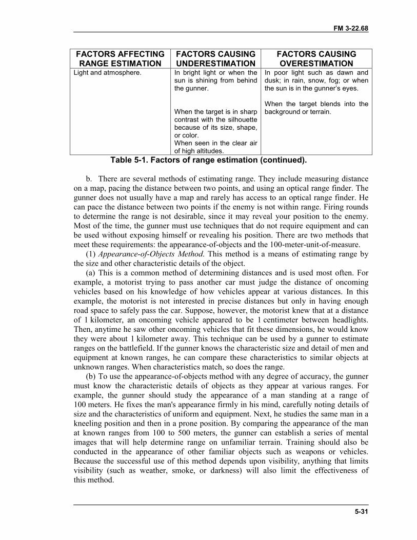
FM 3-22.68
5-31
FACTORS AFFECTINGRANGE ESTIMATION
FACTORS CAUSINGUNDERESTIMATION
FACTORS CAUSINGOVERESTIMATION
Light and atmosphere. In bright light or when thesun is shining from behindthe gunner.
When the target is in sharpcontrast with the silhouettebecause of its size, shape,or color.When seen in the clear airof high altitudes.
In poor light such as dawn anddusk; in rain, snow, fog; or whenthe sun is in the gunner’s eyes.
When the target blends into thebackground or terrain.
Table 5-1. Factors of range estimation (continued).
b. There are several methods of estimating range. They include measuring distanceon a map, pacing the distance between two points, and using an optical range finder. Thegunner does not usually have a map and rarely has access to an optical range finder. Hecan pace the distance between two points if the enemy is not within range. Firing roundsto determine the range is not desirable, since it may reveal your position to the enemy.Most of the time, the gunner must use techniques that do not require equipment and canbe used without exposing himself or revealing his position. There are two methods thatmeet these requirements: the appearance-of-objects and the 100-meter-unit-of-measure.
(1) Appearance-of-Objects Method. This method is a means of estimating range bythe size and other characteristic details of the object.
(a) This is a common method of determining distances and is used most often. Forexample, a motorist trying to pass another car must judge the distance of oncomingvehicles based on his knowledge of how vehicles appear at various distances. In thisexample, the motorist is not interested in precise distances but only in having enoughroad space to safely pass the car. Suppose, however, the motorist knew that at a distanceof 1 kilometer, an oncoming vehicle appeared to be 1 centimeter between headlights.Then, anytime he saw other oncoming vehicles that fit these dimensions, he would knowthey were about 1 kilometer away. This technique can be used by a gunner to estimateranges on the battlefield. If the gunner knows the characteristic size and detail of men andequipment at known ranges, he can compare these characteristics to similar objects atunknown ranges. When characteristics match, so does the range.
(b) To use the appearance-of-objects method with any degree of accuracy, the gunnermust know the characteristic details of objects as they appear at various ranges. Forexample, the gunner should study the appearance of a man standing at a range of100 meters. He fixes the man's appearance firmly in his mind, carefully noting details ofsize and the characteristics of uniform and equipment. Next, he studies the same man in akneeling position and then in a prone position. By comparing the appearance of the manat known ranges from 100 to 500 meters, the gunner can establish a series of mentalimages that will help determine range on unfamiliar terrain. Training should also beconducted in the appearance of other familiar objects such as weapons or vehicles.Because the successful use of this method depends upon visibility, anything that limitsvisibility (such as weather, smoke, or darkness) will also limit the effectiveness ofthis method.
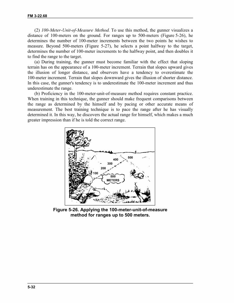
FM 3-22.68
5-32
(2) 100-Meter-Unit-of-Measure Method. To use this method, the gunner visualizes adistance of 100-meters on the ground. For ranges up to 500-meters (Figure 5-26), hedetermines the number of 100-meter increments between the two points he wishes tomeasure. Beyond 500-meters (Figure 5-27), he selects a point halfway to the target,determines the number of 100-meter increments to the halfway point, and then doubles itto find the range to the target.
(a) During training, the gunner must become familiar with the effect that slopingterrain has on the appearance of a 100-meter increment. Terrain that slopes upward givesthe illusion of longer distance, and observers have a tendency to overestimate the100-meter increment. Terrain that slopes downward gives the illusion of shorter distance.In this case, the gunner's tendency is to underestimate the 100-meter increment and thusunderestimate the range.
(b) Proficiency in the 100-meter-unit-of-measure method requires constant practice.When training in this technique, the gunner should make frequent comparisons betweenthe range as determined by the himself and by pacing or other accurate means ofmeasurement. The best training technique is to pace the range after he has visuallydetermined it. In this way, he discovers the actual range for himself, which makes a muchgreater impression than if he is told the correct range.
Figure 5-26. Applying the 100-meter-unit-of-measuremethod for ranges up to 500 meters.
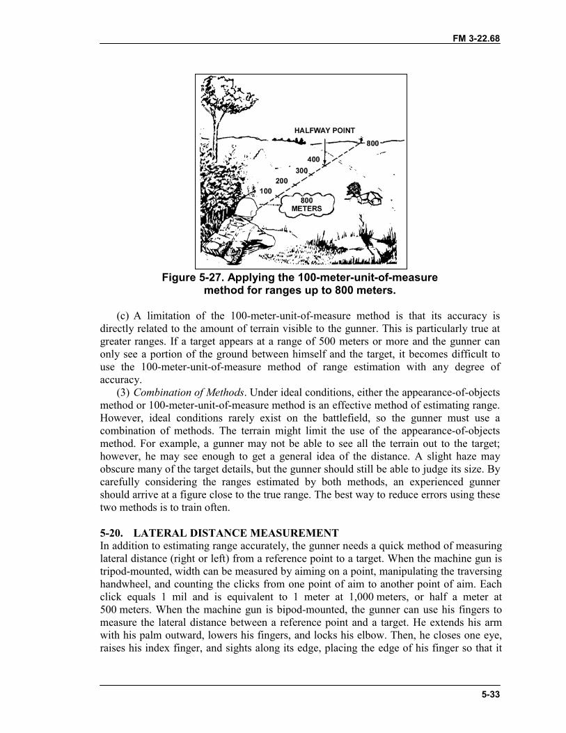
FM 3-22.68
5-33
Figure 5-27. Applying the 100-meter-unit-of-measuremethod for ranges up to 800 meters.
(c) A limitation of the 100-meter-unit-of-measure method is that its accuracy isdirectly related to the amount of terrain visible to the gunner. This is particularly true atgreater ranges. If a target appears at a range of 500 meters or more and the gunner canonly see a portion of the ground between himself and the target, it becomes difficult touse the 100-meter-unit-of-measure method of range estimation with any degree ofaccuracy.
(3) Combination of Methods. Under ideal conditions, either the appearance-of-objectsmethod or 100-meter-unit-of-measure method is an effective method of estimating range.However, ideal conditions rarely exist on the battlefield, so the gunner must use acombination of methods. The terrain might limit the use of the appearance-of-objectsmethod. For example, a gunner may not be able to see all the terrain out to the target;however, he may see enough to get a general idea of the distance. A slight haze mayobscure many of the target details, but the gunner should still be able to judge its size. Bycarefully considering the ranges estimated by both methods, an experienced gunnershould arrive at a figure close to the true range. The best way to reduce errors using thesetwo methods is to train often.
5-20. LATERAL DISTANCE MEASUREMENTIn addition to estimating range accurately, the gunner needs a quick method of measuringlateral distance (right or left) from a reference point to a target. When the machine gun istripod-mounted, width can be measured by aiming on a point, manipulating the traversinghandwheel, and counting the clicks from one point of aim to another point of aim. Eachclick equals 1 mil and is equivalent to 1 meter at 1,000 meters, or half a meter at500 meters. When the machine gun is bipod-mounted, the gunner can use his fingers tomeasure the lateral distance between a reference point and a target. He extends his armwith his palm outward, lowers his fingers, and locks his elbow. Then, he closes one eye,raises his index finger, and sights along its edge, placing the edge of his finger so that it
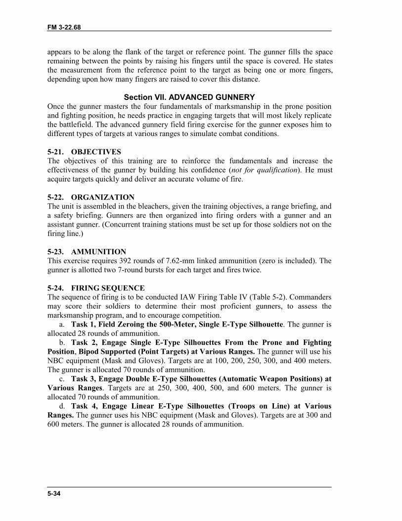
FM 3-22.68
5-34
appears to be along the flank of the target or reference point. The gunner fills the spaceremaining between the points by raising his fingers until the space is covered. He statesthe measurement from the reference point to the target as being one or more fingers,depending upon how many fingers are raised to cover this distance.
Section VII. ADVANCED GUNNERYOnce the gunner masters the four fundamentals of marksmanship in the prone positionand fighting position, he needs practice in engaging targets that will most likely replicatethe battlefield. The advanced gunnery field firing exercise for the gunner exposes him todifferent types of targets at various ranges to simulate combat conditions.
5-21. OBJECTIVESThe objectives of this training are to reinforce the fundamentals and increase theeffectiveness of the gunner by building his confidence (not for qualification). He mustacquire targets quickly and deliver an accurate volume of fire.
5-22. ORGANIZATIONThe unit is assembled in the bleachers, given the training objectives, a range briefing, anda safety briefing. Gunners are then organized into firing orders with a gunner and anassistant gunner. (Concurrent training stations must be set up for those soldiers not on thefiring line.)
5-23. AMMUNITIONThis exercise requires 392 rounds of 7.62-mm linked ammunition (zero is included). Thegunner is allotted two 7-round bursts for each target and fires twice.
5-24. FIRING SEQUENCEThe sequence of firing is to be conducted IAW Firing Table IV (Table 5-2). Commandersmay score their soldiers to determine their most proficient gunners, to assess themarksmanship program, and to encourage competition.
a. Task 1, Field Zeroing the 500-Meter, Single E-Type Silhouette. The gunner isallocated 28 rounds of ammunition.
b. Task 2, Engage Single E-Type Silhouettes From the Prone and FightingPosition, Bipod Supported (Point Targets) at Various Ranges. The gunner will use hisNBC equipment (Mask and Gloves). Targets are at 100, 200, 250, 300, and 400 meters.The gunner is allocated 70 rounds of ammunition.
c. Task 3, Engage Double E-Type Silhouettes (Automatic Weapon Positions) atVarious Ranges. Targets are at 250, 300, 400, 500, and 600 meters. The gunner isallocated 70 rounds of ammunition.
d. Task 4, Engage Linear E-Type Silhouettes (Troops on Line) at VariousRanges. The gunner uses his NBC equipment (Mask and Gloves). Targets are at 300 and600 meters. The gunner is allocated 28 rounds of ammunition.
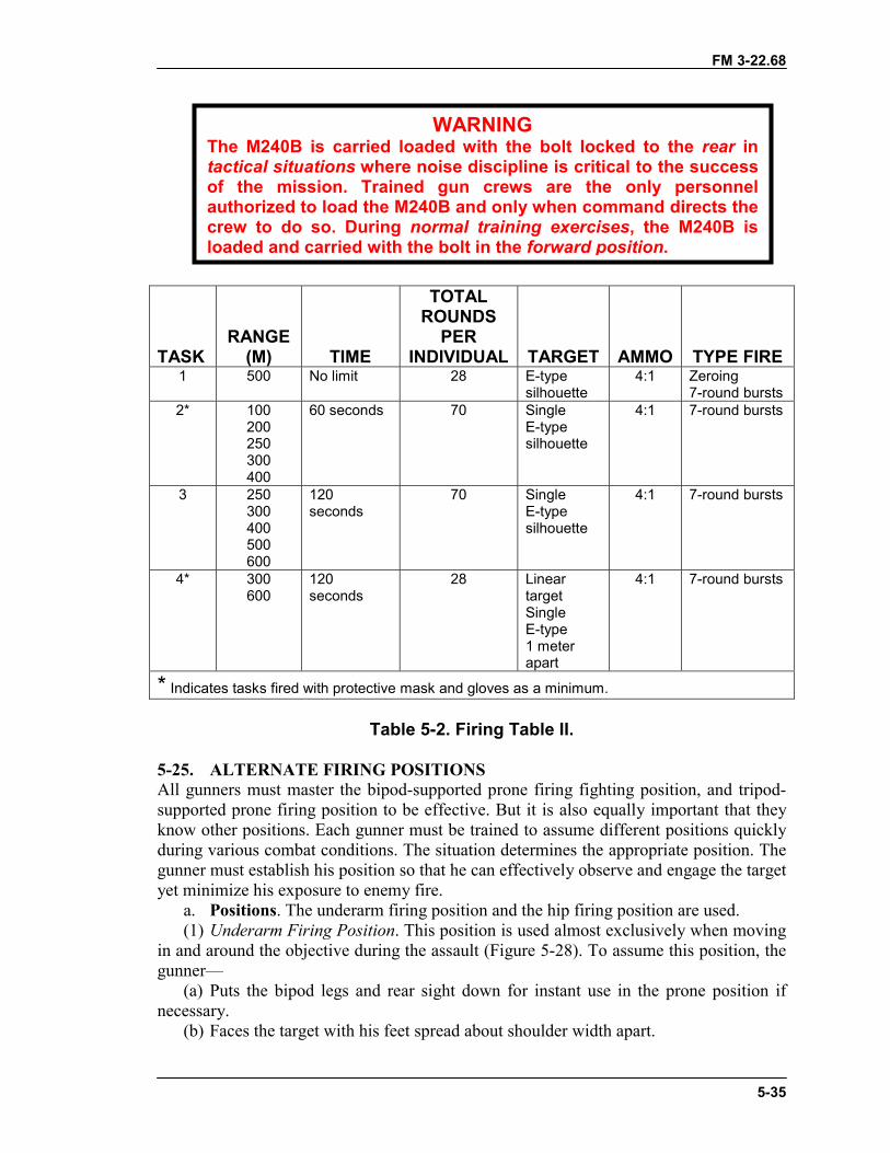
FM 3-22.68
5-35
TASKRANGE
(M) TIME
TOTALROUNDS
PERINDIVIDUAL TARGET AMMO TYPE FIRE
1 500 No limit 28 E-typesilhouette
4:1 Zeroing7-round bursts
2* 100200250300400
60 seconds 70 SingleE-typesilhouette
4:1 7-round bursts
3 250300400500600
120seconds
70 SingleE-typesilhouette
4:1 7-round bursts
4* 300600
120seconds
28 LineartargetSingleE-type1 meterapart
4:1 7-round bursts
* Indicates tasks fired with protective mask and gloves as a minimum.
Table 5-2. Firing Table II.
5-25. ALTERNATE FIRING POSITIONSAll gunners must master the bipod-supported prone firing fighting position, and tripod-supported prone firing position to be effective. But it is also equally important that theyknow other positions. Each gunner must be trained to assume different positions quicklyduring various combat conditions. The situation determines the appropriate position. Thegunner must establish his position so that he can effectively observe and engage the targetyet minimize his exposure to enemy fire.
a. Positions. The underarm firing position and the hip firing position are used.(1) Underarm Firing Position. This position is used almost exclusively when moving
in and around the objective during the assault (Figure 5-28). To assume this position, thegunner—
(a) Puts the bipod legs and rear sight down for instant use in the prone position ifnecessary.
(b) Faces the target with his feet spread about shoulder width apart.
WARNINGThe M240B is carried loaded with the bolt locked to the rear intactical situations where noise discipline is critical to the successof the mission. Trained gun crews are the only personnelauthorized to load the M240B and only when command directs thecrew to do so. During normal training exercises, the M240B isloaded and carried with the bolt in the forward position.
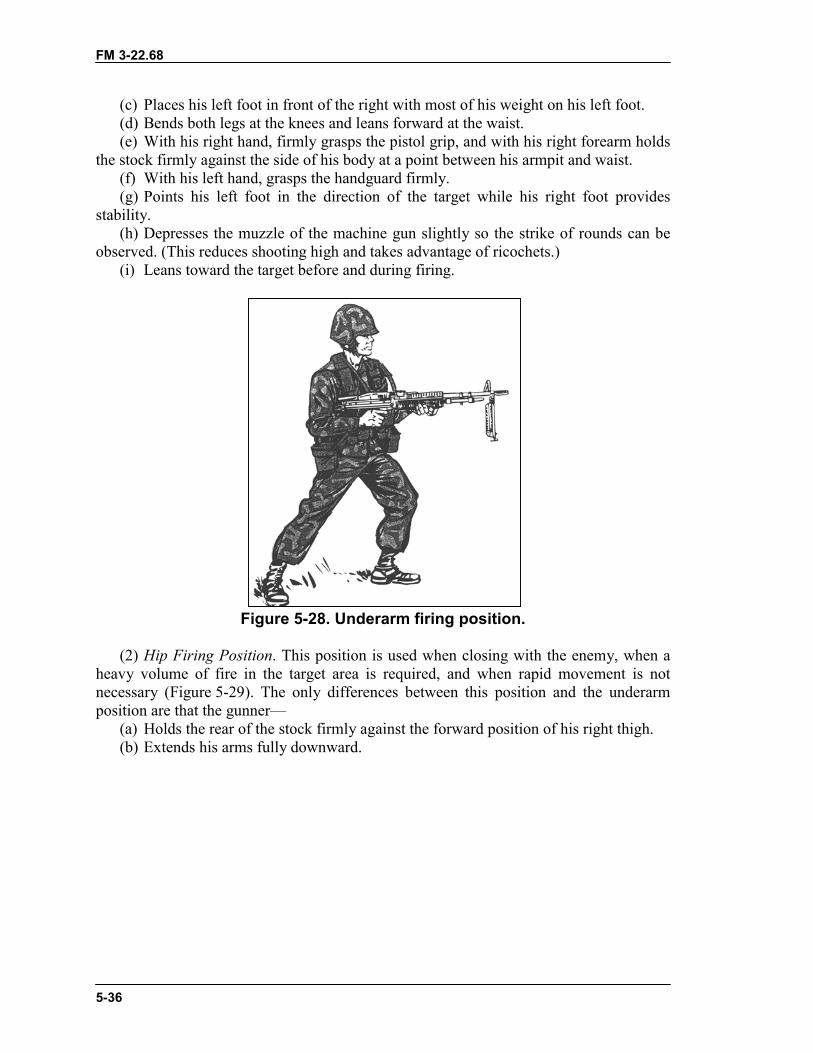
FM 3-22.68
5-36
(c) Places his left foot in front of the right with most of his weight on his left foot.(d) Bends both legs at the knees and leans forward at the waist.(e) With his right hand, firmly grasps the pistol grip, and with his right forearm holds
the stock firmly against the side of his body at a point between his armpit and waist.(f) With his left hand, grasps the handguard firmly.(g) Points his left foot in the direction of the target while his right foot provides
stability.(h) Depresses the muzzle of the machine gun slightly so the strike of rounds can be
observed. (This reduces shooting high and takes advantage of ricochets.)(i) Leans toward the target before and during firing.
Figure 5-28. Underarm firing position.
(2) Hip Firing Position. This position is used when closing with the enemy, when aheavy volume of fire in the target area is required, and when rapid movement is notnecessary (Figure 5-29). The only differences between this position and the underarmposition are that the gunner—
(a) Holds the rear of the stock firmly against the forward position of his right thigh.(b) Extends his arms fully downward.
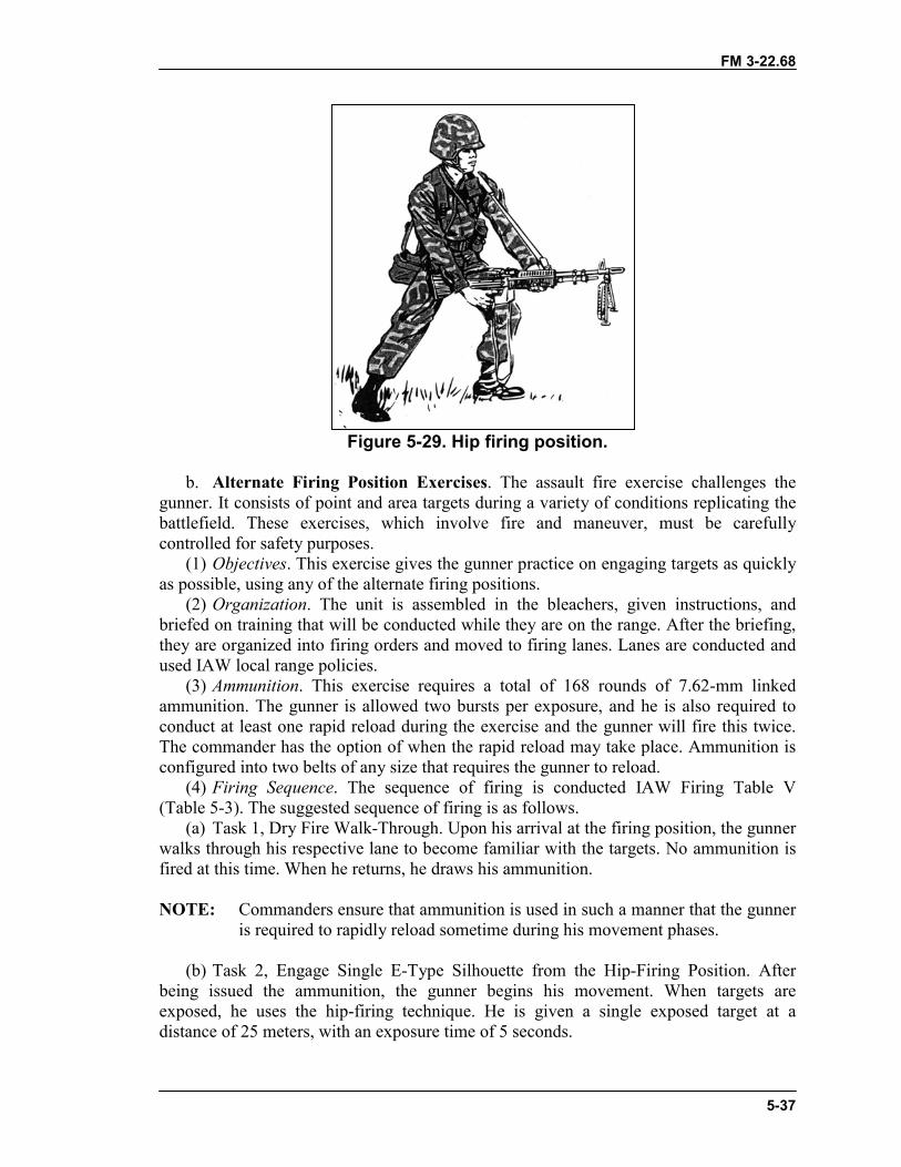
FM 3-22.68
5-37
Figure 5-29. Hip firing position.
b. Alternate Firing Position Exercises. The assault fire exercise challenges thegunner. It consists of point and area targets during a variety of conditions replicating thebattlefield. These exercises, which involve fire and maneuver, must be carefullycontrolled for safety purposes.
(1) Objectives. This exercise gives the gunner practice on engaging targets as quicklyas possible, using any of the alternate firing positions.
(2) Organization. The unit is assembled in the bleachers, given instructions, andbriefed on training that will be conducted while they are on the range. After the briefing,they are organized into firing orders and moved to firing lanes. Lanes are conducted andused IAW local range policies.
(3) Ammunition. This exercise requires a total of 168 rounds of 7.62-mm linkedammunition. The gunner is allowed two bursts per exposure, and he is also required toconduct at least one rapid reload during the exercise and the gunner will fire this twice.The commander has the option of when the rapid reload may take place. Ammunition isconfigured into two belts of any size that requires the gunner to reload.
(4) Firing Sequence. The sequence of firing is conducted IAW Firing Table V(Table 5-3). The suggested sequence of firing is as follows.
(a) Task 1, Dry Fire Walk-Through. Upon his arrival at the firing position, the gunnerwalks through his respective lane to become familiar with the targets. No ammunition isfired at this time. When he returns, he draws his ammunition.
NOTE: Commanders ensure that ammunition is used in such a manner that the gunneris required to rapidly reload sometime during his movement phases.
(b) Task 2, Engage Single E-Type Silhouette from the Hip-Firing Position. Afterbeing issued the ammunition, the gunner begins his movement. When targets areexposed, he uses the hip-firing technique. He is given a single exposed target at adistance of 25 meters, with an exposure time of 5 seconds.
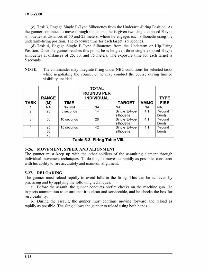
FM 3-22.68
5-38
(c) Task 3, Engage Single E-Type Silhouettes from the Underarm-Firing Position. Asthe gunner continues to move through the course, he is given two single exposed E-typesilhouettes at distances of 50 and 25 meters, where he engages each silhouette using theunderarm-firing position. The exposure time for each target is 5 seconds.
(d) Task 4, Engage Single E-Type Silhouettes from the Underarm or Hip-FiringPosition. Once the gunner reaches this point, he is be given three single exposed E-typesilhouettes at distances of 25, 50, and 75 meters. The exposure time for each target is5 seconds.
NOTE: The commander may integrate firing under NBC conditions for selected taskswhile negotiating the course, or he may conduct the course during limitedvisibility unaided.
TASKRANGE
(M) TIME
TOTALROUNDS PERINDIVIDUAL
TARGET AMMOTYPEFIRE
1 NA No limit NA NA NA NA2 25 5 seconds 14 Single E-type
silhouette4:1 7-round
bursts3 50 10 seconds 28 Single E-type
silhouette4:1 7-round
bursts4 25
5075
15 seconds 42 Single E-typesilhouette
4:1 7-roundbursts
Table 5-3. Firing Table VIII.
5-26. MOVEMENT, SPEED, AND ALIGNMENTThe gunner must keep up with the other soldiers of the assaulting element throughindividual movement techniques. To do this, he moves as rapidly as possible, consistentwith his ability to fire accurately and maintain alignment.
5-27. RELOADINGThe gunner must reload rapidly to avoid lulls in the firing. This can be achieved bypracticing and by applying the following techniques.
a. Before the assault, the gunner conducts prefire checks on the machine gun. Heinspects ammunition to ensure that it is clean and serviceable, and he checks the box forserviceability.
b. During the assault, the gunner must continue moving forward and reload asrapidly as possible. The sling allows the gunner to reload using both hands.
FM 3-22.68
6-1
CHAPTER 6TRAIN-THE-TRAINER PROGRAM
This chapter helps the leader develop a good train-the-trainerprogram. The goal of this program is to certify qualified machine guntrainers and achieve a high state of combat readiness. Knowledgeable,small-unit leaders and trainers are the key to any successfulmarksmanship training program; however, the entire leadership must beinvolved in the execution of training to standard. An effective train-the-trainer program reflects the priority, emphasis, and interest of the leadersand trainers to see that execution of training to standard is achieved.
The objectives of the train-the-trainer program are to develop in everymachine gun trainer the confidence, willingness, knowledge, and skillsrequired to consistently train their soldiers to be effective in combat.
6-1. MISSION-ESSENTIAL TASK LISTThe unit’s combat mission is considered when establishing training priorities. This notonly applies to the tasks selected but to the conditions under which the tasks are to bepreformed. The tasks for the METL are developed for both defensive and offensiveoperations. Machine gun marksmanship will be a critical individual, crew and leader task.Each commander should develop a METL and organize a training program that devotesadequate time to conduct marksmanship training.
6-2. TRAINER ASSESSMENTThe leaders are also involved in determining the proficiency of potential trainers byreviewing the following information.
a. Selection. Trainers should be selected from the most highly qualified soldiersavailable within the unit. These soldiers should be knowledgeable of the machine guns, ahigh degree of proficiency in applying the fundamentals, and demonstrate a motivatedattitude for marksmanship training. The leaders must ensure that a high level ofproficiency is maintained. Knowledgeable trainers are the key to any successful trainingprogram.
b. Trainer Course. Once the leaders have identified these soldiers possessing therequired knowledge, skills, and motivation in machine gun marksmanship, they must thenensure this knowledge can be effectively taught to other soldiers.
c. Training. There are several available means that may be used in the progressionof trainer training or that can easily be tailored to the certain needs of the command. Themore time and training initially invested, the better the trainer will be. The leaders shouldperiodically evaluate each trainer and replace any that loses his motivation or desire. Tomaintain interest in the program, leaders should have a way of promoting competitionand awards the best trainer.
6-3. ASSISTANT TRAINERS AND CADRE COACHESAssisting the trainer and coaching a soldier to fire the machine gun are highly technicaljobs that must be done well. The most valuable soldiers in the program are those who notonly have obtained a high standard, but those who can effectively teach this knowledge to
FM 3-22.68
6-2
others. Once the individual is consistent in this train-the-trainer program, he can thendevelop into a competent assistant trainer. It is worth the effort to train these individualsto become a successful assistant trainer, because experience has shown that such trainingalso develops leadership ability.
a. The primary responsibility of assistant trainers is to train individuals in theeffective use of the machine gun. In addition, assistant trainers are responsible forenforcing safety regulations. They must maintain strict discipline on the firing lane at alltimes and constantly enforce compliance with the range regulations and trainingguidance.
b. To be an assistant trainer, a soldier must know the principles of accurate firingand coaching techniques, and he must have the following qualifications as well.
(1) Knowledge. The assistant trainer must know this manual. He must be prepared toaccurately answer any question on the subject of marksmanship. Then, he must develophis ability to observe the actions of the soldier quickly and to correct them with soundrecommendations.
(2) Patience. Gunners can be persuaded to accept the principles and procedures bypatient repetition and demonstration.
(3) Understanding. The assistant trainers that have good "firing lane manners"enhance the success of training. Training new gunners is stressful to the soldiers and thetrainers. The soldier may be sensitive to abruptness, impatience, or a lack of sympathywith his difficulties; and he will immediately react unfavorably to evidence of suchattitude on the part of the coach.
(4) Consideration. Most soldiers, even those who do not fire well, enjoy firing andbegin with a positive interest in their performance on the range. If the assistant trainer isconsiderate of his pupils' feelings from the beginning and encourages them throughouttheir training, he will find training a pleasant and rewarding duty.
(5) Ability to Maintain Respect. When a soldier is assigned the duties of assistanttrainer, he too is an expert and should receive the same respect as the primary trainer. Theassistant trainer must retain that respect throughout his contact with students by showinga thorough knowledge of his subject in a dignified manner.
(6) Alertness. Even the most capable student may forget or neglect some essentialpoint in his instruction in the excitement of firing on the range. The assistant trainer mustalways be alert and patiently correct him as often as necessary. He must keep the gunnersencouraged throughout the instruction by making the most of all progress. The assistanttrainer must not allow his students to become discouraged or to lose interest.
(7) Helpful Attitude. When assisting on the range, as in most other lines ofinstruction, a combative, hard-boiled attitude is rarely effective.
(8) Ability to Provide Encouragement. The assistant trainer can encourage hissoldiers by convincing them there is no mystery about good firing: The weapon andammunition are mechanically developed for accuracy. The assistant trainer is there toassist the gunner and to help him gain the experience that produces a good marksman.
6-4. PROGRAM PHASESSince firing is a learning process, certain prerequisites must be satisfied before a trainerpasses from one phase of marksmanship to another. The trainer must qualify with themachine gun (the trainer must pass all tasks and qualify on the 10-meter and transition
FM 3-23.68
6-3
fire) that he will be teaching to the machine gunners in his unit. To obtain maximumresults on the battlefield, the machine gunners are trained in the fundamentals before theyengage a combat target. The phases of the train-the-trainer program are to develop thisstructure in the most progressive manner. They are sequenced to train-the-trainer inteaching tasks necessary to produce a quality machine gunner and a machine gun team.
a. Preliminary Gunnery. The machine gunners must receive this training beforelive firing. It is during this phase that sound foundations of good firing principles areconstructed, reviewed, and reinforced. The degree of proficiency obtained or retained bythe machine gunners depends on the foundation built during this phase. Correct firing andgood safety habits must become natural. Drilling of the fundamentals and continuedleader emphasis will bring the greatest return in the shortest time. Proper firing is aphysical skill, which must be learned. When practiced, the process becomes a learnedskill that will be retained. However, good firing is a perishable skill. All machine gunnersmust periodically familiarize themselves with the fundamentals regardless of their yearsof marksmanship experience. Even experienced machine gunners will develop adeficiency in applying certain fundamentals (for example, overconfidence).
b. Basic Gunnery. This training teaches the trainers how to qualify, plan, set up,and conduct 10-meter and transition firing exercises on the available ranges.
c. Advanced Gunnery. This training teaches the trainer how to develop teamworkamong the machine gun teams. This training also gives them confidence in their ability todeliver a large volume of accurate fire against targets. During this phase, the trainer isresponsible for the conduct of assault firing exercises. These exercises consist of assaultfire, NBC assault fire, and field fire on available ranges.
6-5. TRAINING TASKSThis paragraph assists trainers in effectively training soldiers assigned to any machinegun team. It explains the tasks, organization, equipment needed, and instruction sequencefor the three phases of gunnery. However, unit SOPs or post regulations may directincreases or decreases in these prescribed requirements.
a. Phase I, Preliminary Gunnery Training. This phase covers the basics that eachtrainer must know to teach the general care and maintenance of the machine gun.
(1) Task 1: (071-312-3025) Disassemble the Machine Gun. The trainer stresses thatthis task is not done hurriedly, because the soldiers may damage parts of themachine gun.
(a) Equipment Needed. A table is needed for placement of the machine gun so thatthe soldiers may better see the removal of parts of the gun. Nomenclature charts or matsare material aids in explaining mechanical training, and they help the gunners learn thenomenclature of parts.
(b) Class Organization. One assistant trainer is assigned for each group if possible;otherwise, assistant trainers are placed where they can supervise assigned groups.
(c) Sequence of Training. The trainer presents a brief history of the machine guns. Hestresses the combat role it has played and the mission it is assigned. He emphasizes thepurpose, scope, and importance of the instruction to be presented. He gives a briefdescription of the operation, general data, and exterior nomenclature of the machine gun.Assistant trainers should clear and disassemble the machine gun as the trainer explainsthe procedures. The gunners then practice until they become skilled in disassembly and
FM 3-22.68
6-4
can demonstrate this task to standards to either the trainer or assistant trainers. Thispractice often encourages the gunners to practice during free time and develops theirindividual skill and initiative.
(2) Task 2: (071-025-0001) Perform Operator Maintenance on the Machine Gun.The subtasks are inspect, clean, and lubricate.
(a) Equipment Needed. The trainer needs one cleaning rod and one dummy round foreach machine gun, bore cleaner, (one cleaning reamer, one combination regulatorscraper, one combination scraper and extractor tool), lubricating oil, patches, and rags.The trainer displays all the available cleaning materials, lubricants, and rustpreventatives.
(b) Class Organization. One assistant trainer is assigned for each group if possible;otherwise, the assistant trainers are placed where they can supervise assigned groups.
(c) Sequence of Training. The trainer emphasizes meticulous cleaning, lubrication,inspection, and preventive maintenance to ensure performance. The care and cleaningperiod is used to further the gunner's knowledge of the nomenclature and skill indisassembly. The trainer emphasizes inspection, care, and preventive maintenance duringcombat conditions, which is the final test of the weapon maintenance program. Practicalwork is conducted. The trainer points out the differences in care and cleaning followingan NBC attack. He emphasizes the importance of frequent inspection as a means ofensuring proper maintenance of the machine guns.
(3) Task 3: (071-312-4025) Assemble the Machine Gun.(a) Equipment Needed. A table is needed for placement of the machine gun so that
the soldiers may better see the removal of the parts. Nomenclature charts or mats arematerial aids in explaining mechanical training, and they help the gunners to learn thenomenclature of parts.
(b) Class Organization. One assistant trainer is assigned for each group if possible;otherwise, assistant trainers are placed where they can supervise assigned groups.
(c) Sequence of Training. Assistant trainers should assemble the machine gun as thetrainer explains the procedures. The gunners practice until they become proficient inassembly and can demonstrate this task to standards to either the trainer or assistanttrainer.
(4) Task 4: (071-312-4026) Explain the Operation of the Machine Gun.(a) Equipment Needed. One machine gun placed on a table; one belt of six dummy
rounds (5.56-mm or 7.62-mm linked), and a cleaning rod for each gunner.(b) Class Organization. One assistant trainer is assigned for each group if possible;
otherwise, assistant trainers are placed where they can supervise assigned groups.(c) Sequence of Training. The trainer explains and the assistant trainer demonstrates
loading, unloading, and clearing the machine gun. The trainer stresses the safety factorsinvolved. The assistant trainer demonstrates letting the bolt go forward when the barrel isout of the machine gun. (Damage could be done to the chamber or the face of the bolt ifthe barrel is left in.)
(5) Task 5: (071-312-3026) Explain the Functioning of the Machine Gun.(a) Equipment Needed. One machine gun for each gunner as in previous mechanical
training instruction. Graphic training aids are useful if the class is about platoon size;otherwise, GTAs may be made available for study and discussion during breaks.
FM 3-23.68
6-5
(b) Class Organization. One assistant trainer is assigned for each group if possible;otherwise, assistant trainers are placed where they can supervise assigned groups.
(c) Sequence of Training. Functioning is divided into eight steps�feeding,chambering, locking, firing, unlocking, extracting, ejecting, and cocking. The assistanttrainer duplicates each demonstration on the machine gun with each group. Functioningis taught by seeing how the parts work, rather than by memorizing the text. The trainertests retention of the training by asking questions concerning the steps of functioning.
(6) Task 6: (071-312-3029) Explain Malfunction, Stoppage, Immediate Action, andRemedial Action.
(a) Equipment Needed. A table is needed for placement of the machine gun so thatthe soldiers may better see the removal of parts. Nomenclature charts or mats are materialaids in explaining mechanical training, and they help the gunners learn the nomenclatureof parts.
(b) Class Organization. One assistant trainer is assigned for each group if possible;otherwise, assistant trainers are placed where they can supervise assigned groups.
(c) Sequence of Training. Malfunction and stoppages charts may be used as a guidein presenting instruction. These charts may be available from the local Training SupportCenter or the trainer can use tables of the appropriate chapters for the machine gun. Thetrainer stresses precision in detecting the cause and reducing stoppages. As the gunnersprogress, the trainer has them concentrate on speed in applying immediate action andother methods of reducing a stoppage. He stresses safety precautions in connection with ahangfire or cook off.
(7) Task 7: (071-312-3030) Explain the Procedures for Sight Adjustments andMechanical Zero.
(a) Equipment Needed. A table is needed for placement of the machine gun so thatthe soldiers may better see the removal of parts. Nomenclature charts or mats are materialaids in explaining mechanical training, and they help the gunners learn the nomenclatureof parts, plus tripod. (Front sight adjustment tool for the M240B.)
(b) Class Organization. One assistant trainer is assigned for each group if possible;otherwise, assistant trainers are placed where they can supervise assigned groups.
(c) Sequence of Training. Assistant trainers demonstrate, while trainers describe theproper techniques to mechanically zero the machine gun. The trainer then describes sightadjustments. The trainer emphasizes the number of clicks in relation to the targets forM240B only.
(8) Task 8: (071-020-0006) Explain the M122 or M122A1 Tripod with AppropriateMounting Equipment.
(a) Equipment Needed. One machine gun mounted on an M122 or M122A1 tripodcomplete with appropriate mounting equipment placed on a table. GTAs and film strips ifavailable.
(b) Class Organization. One assistant trainer is assigned for each group if possible;otherwise, assistant trainers are placed where they can supervise assigned groups.
(c) Sequence of Training. The assistant trainers demonstrate, while the trainersdescribe the general nomenclature, data, functioning, and operation of the tripod with theappropriate mounting equipment.
(9) Task 9: (071-020-0006) Place the Machine Gun Into Operation on the M122 orM122A1 Tripod with Appropriate Mounting Equipment Using Crew Exercises.
FM 3-22.68
6-6
(a) Equipment Needed. Basic TOE and individual equipment.(b) Class Organization. Gunners are divided into three-man crews. To aid control and
supervision, equipment is aligned with engineer tape or wire with the gunners in filesbehind the equipment.
(c) Sequence of Training. Assistant trainers demonstrate, while trainers explain howto place the machine gun into operation on the tripod with the appropriate mountingequipment. The crew drill is the first step in developing teamwork. Precision is a must foreach crewmember. Crewmembers practice their duties with precision. Speed is increasedas precision is attained. In advanced training, speed drills create interest and stimulatecompetition, while developing teamwork and testing individual crew performance. Awell-trained crew can place the machine gun into action or take it out of action in25 seconds.
(10) Task 10: (071-312-3025) Demonstrate Fundamentals of Marksmanship.(a) Equipment Needed. One machine gun and a basic machine gun target for each
firing lane on a range of suitable training area equipped with a prone and fightingposition.
(b) Class Organization. The maximum number of required gunners is on the firingline or suitable training area.
(c) Sequence of Training. The trainer conducts conference, demonstration, andpractical work on the fundamentals of marksmanship (steady position, aim, breathcontrol, trigger control).
(11) Task 11: (071-312-3026) Demonstrate Fundamentals of Firing Positions.(1) Equipment Needed. One machine gun and a basic machine gun target for each
firing lane on a range of suitable training area equipped with a prone and fightingposition.
(2) Class Organization. The maximum number of required gunners is on the firingline or suitable training area.
(3) Sequence of Training. The trainer conducts conference, demonstration, andpractical work on the fundamentals of marksmanship (steady position, aim, breathcontrol, trigger control).
(12) Task 12: (071-312-3027) Demonstrate Fundamentals of Traverse and Search.(a) Equipment Needed. One machine gun and a basic machine gun target for each
firing lane on a range of suitable training area equipped with a prone and fightingposition.
(b) Class Organization. The maximum number of required gunners is on the firingline or suitable training area.
(c) Sequence of Training. The trainer conducts conference, demonstration, andpractical work on the fundamentals of marksmanship (steady position, aim, breathcontrol, trigger control).
(13) Task13: (071-312-3031) Demonstrate Fundamentals of Engaging Night, NBC,and Moving Targets.
(a) Equipment Needed. One machine gun, one night vision sight, one protective maskwith gloves for each gunner, and a basic machine gun target for each firing lane on arange of suitable training area equipped with a prone and fighting position.
(b) Class Organization. The maximum number of required gunners is on the firingline or suitable training area.
FM 3-23.68
6-7
(c) Sequence of Training. The trainer conducts conference, demonstration, andpractical work on the fundamentals of marksmanship (steady position, aim, breathcontrol, trigger control).
(14) Task 14: (071-025-0007) Demonstrate Fire Commands.(a) Equipment Needed. One machine gun and a basic machine gun target for each
firing lane on a range of suitable training area equipped with a prone and fightingposition. GTAs and film strips if available.
(b) Class Organization. The maximum number of required gunners is on the firingline or suitable training area.
(c) Sequence of Training. The trainer conducts conference, demonstration, andpractical work on the fundamentals of marksmanship (steady position, aim, breathcontrol, trigger control), plus, the trainer gives the fire commands. (See Chapter 5.)
(15) Task 15: (071-025-0007) Execute Dry-Fire Exercises.(a) Equipment Needed. One machine gun and a basic machine gun target for each
firing lane on a range of suitable training area equipped with a prone and fightingposition.
(b) Class Organization. The maximum number of required gunners is on the firingline or suitable training area.
(c) Sequence of Training. The trainer conducts conference, demonstration, andpractical work on the fundamentals of marksmanship (steady position, aim, breathcontrol, trigger control), plus, the trainer give the fire commands. (See Chapter 4.)
b. Phase II, Basic Gunnery Training. The information learned in this phase isessential to the development of the trainer who is to conduct the 10-meter firing, daytransition firing, day NBC firing, and night transition instructional firing for the machinegun. The trainer must be qualified or certified on Phase I before moving to Phase II.
(1) Task 16: ( 071-312-3031) Conduct 10-Meter Firing.(a) Equipment Needed. One machine gun and basic machine gun target (10-meter)
for each firing lane; stopwatches; patches; and cleaning rods. Sound equipment isdesirable during firing.
(b) Class Organization. The maximum number of required gunners is on the firingline with the remainder receiving concurrent instruction in the rear training area.
(c) Sequence of Instruction. The unit is assembled, given instructions, and briefed onthe training that will be conducted while they are on the range. The trainer conductsconference, demonstration, and practical work on emplacing the machine gun on the firinglane. He places emphasis on preparation of the machine gun for firing, including safetychecks. The interval between the two portions of the control command should besufficient to permit the execution of the command and to allow the assistant gunner toperform his duties. Assistant gunners are required to perform their duties quickly andprecisely. During practice, the trainer must ensure that the gunner is in the proper positionbefore he is permitted to shoot. The OIC controls all firing. If space permits, all personnelare placed on the firing line. After the briefing, they are organized into firing orders andmoved to firing lanes. Lanes are conducted IAW local range policies. Firing is conductedas described in Chapter 4. Concurrent training stations:
� Mechanical training.� Care and cleaning.� Any other machine gun subjects in which additional training is needed.
FM 3-22.68
6-8
(2) Task 17: (071-312-3031) Conduct Daytime Transition Fire on the MultipurposeMachine Gun Range.
(a) Equipment Needed. Requires one machine gun for each firing lane, single anddouble E-type silhouette targets, and cleaning rods. Sound equipment is desirable duringfiring.
(b) Class Organization. Preferably, one gunner and one assistant gunner for eachfiring lane. Personnel not required in the operation of the range should receive concurrenttraining in rear area.
(c) Sequence of Instruction. The unit is assembled, given instructions, and briefed onthe training that will be conducted while they are on the range. Before the conference anddemonstration of firing, the trainer briefly reviews range estimation and techniques ofadjustment. He also explains the characteristics of machine gun fire and their effect onfield targets. The machine guns are zeroed at a known distance on the transition range.The gunner receiving the instruction should do the zeroing. The lane NCO requires thegunner to be in the correct position before letting him fire. The assist gunner helps thegunner in locating the targets and aids him in hitting the targets. The acting safety NCOmay assist the assist gunner in locating the targets, but he is not permitted to aid in rangeestimation or fire adjustment. After the gunners complete this exercise, the gunner andassist gunner rotates duties. After completion of both gunner and assist gunner, the nextgun team moves up. The OIC controls all firing. If space permits, all personnel are placedon the firing line. After the briefing, they are organized into firing orders and moved tofiring lanes. Lanes are conducted IAW local range policies. Firing is conducted asdescribed in Chapter 4. Concurrent training stations:
� Mechanical training.� Care and cleaning.� Any other machine gun subjects in which additional training is needed.
(3) Task 18: (071-010-0006) Demonstrate Fundamentals of Engaging NBC Targets.(a) Equipment Needed. One machine gun, protective mask and gloves for every
gunner, and a basic machine gun target (10-meter) for each firing lane on a range ofsuitable training area equipped with a prone and fighting position.
(b) Class Organization. The maximum number of required teams is on the firing lineor suitable training area.
(c) Sequence of Training. The unit is assembled, given instructions, and briefed onthe training that will be conducted while they are on the range. The trainer conductsconference, demonstration, and practical work on the fundamentals of marksmanship(steady position, aim, breath control, trigger control) while wearing the protective maskand gloves. (Same as Task 16.) After the briefing, they are organized into firing ordersand moved to firing lanes. Lanes are conducted IAW local range policies. Firing isconducted as described in Chapter 4, Firing Tables I or IV. Concurrent training stations,using sand tables, charts, diagrams, or terrain, are set up to review rapid reloadingtechniques while wearing a protective mask and gloves:
� Mechanical training.� Care and cleaning.� Any other machine gun subjects in which additional training is needed.
FM 3-23.68
6-9
(4) Task 19: (071-025-0007) Conduct NBC Familiarization Transition Fire.(a) Equipment Needed. Requires protective mask and gloves, one machine gun, and
appropriate ammunition for each firing lane, single and double E-type silhouette targets,and cleaning rods. Sound equipment is desirable during firing.
(b) Class Organization. Preferably, one gunner and one assistant gunner for eachfiring lane. Personnel not required in the operation of the range should receive concurrenttraining in rear area.
(c) Sequence of Instruction. The unit is assembled, given instructions and briefed onthe training that will be conducted while they are on the range. The trainer conductsconference, demonstration, and practical work on the fundamentals of marksmanship(steady position, aim, breath control, trigger control) while wearing the protective maskand gloves. (Same as Task 16.) After the briefing, they are organized into firing ordersand moved to firing lanes. Lanes are conducted IAW local range policies. Firing isconducted as described in Chapter 4, Firing Tables II or V. Concurrent training stations,using sand tables, charts, diagrams, or terrain, are set up to review rapid reloadingtechniques while wearing a protective mask and gloves:
� Mechanical training.� Care and cleaning.� Any other machine gun subjects in which additional training is needed.
(5) Task 20: (071-010-0001) Conduct Nighttime Transition Fire.(a) Equipment Needed. One machine gun for each firing lane with appropriate night
vision sight, and appropriate ammunition for each firing lane, single and double E-typesilhouette targets, and cleaning rods. Sound equipment is desirable during firing.
(b) Class Organization. The firing area should have seating for the entire groupduring conferences. After the conference, the group is divided into small groups forpractical work under the control of the assistant trainers. The OIC controls all firing. Ifspace permits, all personnel are placed on the firing line. Requirements for the variousexercises should be simple and progressive. If possible, the trainer selects terrain for thesubject; otherwise, he applies the subject to the terrain.
(c) Sequence of Instruction. The unit is assembled, given instructions, and briefed onthe training that will be conducted while they are on the range. Before the conference anddemonstration, the trainer conducts the preparatory exercises of mounting the night visionsight and seating, boresighting, and zeroing procedures for the sight. He should alsoreview and discuss range estimation, techniques of fire, adjustment, and characteristics ofthe machine gun fire. The machine gun should be zeroed to the sight using the night fireprocedures in Chapter 4, Firing Tables III or VI. The acting safety NCO for each lanerequires the gunner to be in the correct position before letting him fire. The OIC controlsall firing. If space permits, all personnel are placed on the firing line. At the completionof the exercise, the next gunner moves up. After the briefing, they are organized intofiring orders and moved to firing lanes. Lanes are conducted IAW local range policies.Firing is conducted as described in Chapter 4. Firing Tables III or VI. Concurrent trainingstations:
� Mechanical training.� Care and cleaning� Any other machine gun subjects in which additional training is needed.
FM 3-22.68
6-10
c. Phase III, Advanced Gunnery Training. This training phase enables the trainerto develop his advanced skills. (See Chapter 5.)
(1) Task 21: (071-025-0007) Conduct Day Assault Fire.(a) Equipment Needed. One machine gun and appropriate ammunition for each
firing lane.(b) Class Organization. The multipurpose machine gun transition range is used if the
installation has one. If need be, the lanes are modified so that the gunner has a trail of atleast 150 meters in front of the weapon position. The training area should have seating forthe entire group during conferences. After the conferences, the group is divided intofiring orders. If the group is large, two firing orders are placed on the firing line and allother personnel go to the concurrent training area for practical work under the control ofthe assistant gunners. The OIC controls all firing. If the group is small, all personnel go tothe firing line at once. Requirements for the various exercises should be simple andprogressive. If possible, the trainer selects terrain for the subject; otherwise, he appliesthe subject to the terrain.
(c) Sequence of Instruction. The unit is assembled, given instructions, and briefed onthe training that will be conducted while they are on the range. After the briefing, they areorganized into firing orders and moved to firing lanes. Lanes are conducted IAW localrange policies. Firing is conducted as described in Chapter 5. Concurrent trainingstations, using sand tables, charts, diagrams, or terrain, are set up to review rapidreloading techniques. The OIC controls all firing. If space permits, all personnel areplaced on the firing line.
� Underarm-firing position.� Hip-firing position.� Rapid reloading techniques.� Any other machine gun subjects in which additional training is needed.
(2) Task 22: (071-025-0009) Conduct NBC Assault Fire With the Machine Gun.(a) Equipment Needed. Requires protective mask and gloves, one machine gun, and
appropriate ammunition for each firing lane.(b) Class Organization. The maximum number of required gunners is on the firing
line with the remainder receiving concurrent instruction in the rear training area.(c) Sequence of Instruction. The unit is assembled, given instructions, and briefed on
the training that will be conducted while they are on the range. After the briefing, they areorganized into firing orders and moved to firing lanes. Lanes are conducted IAW localrange policies. Firing is conducted as described in Chapter 5. Concurrent trainingstations, using sand tables, charts, diagrams, or terrain, are set up to review rapidreloading techniques while wearing a protective mask and gloves:
� Underarm-firing position while wearing a protective mask and gloves.� Hip-firing position while wearing a protective mask and gloves.� Rapid reloading techniques while wearing a protective mask and gloves.� Any other machine gun subjects in which additional training is needed.
FM 3-23.68
6-11
6-6. TRAINER CERTIFICATION PROGRAMThe certification program standardizes procedures for certifying and sustaining theproficiency of trainers. Their technical expertise must be continuously refreshed andupdated, and leaders must manage it closely. One of the goals of the program is for thetrainer to know the training mission.
a. Training Base. The training base can expect the same personnel changes as anyother organization. Soldiers assigned as machine gun trainers have varying experienceand knowledge of training procedures and methods. Therefore, the trainer certificationprogram must address these variables. As a minimum, formal records document thetrainer’s progress in the certification program. All machine gun trainers must completethe three phases of machine gun training, and they must update their training quarterly.
b. Certification Program Outline. All trainers must attend, then conduct, all phasesof the train-the-trainer program. Certified trainers have demonstrated the ability to trainsoldiers, to diagnose and correct problems, and to achieve standards. Those who fail toattend or fail any phase of the diagnostic examination will be assigned to subsequenttraining. The personnel designated to present instruction must complete the phases of theprogram in the prescribed sequence.
(1) Phase I, Program Orientation. In order for leaders to certify trainers, the trainersmust visit training sites and ranges and demonstrate an understanding of—
� The certification program concept.� The unit’s marksmanship training outline and strategy.� Issued reference materials and when to use which.(2) Phase II, Preliminary Gunnery. During Phase II, the trainer must demonstrate his
mastery of the fundamentals of marksmanship. He should complete within two weeksafter completing Phase I. Leaders should review the following fundamentals. They recordand maintain the results of this review on a trainer's progression sheet IAW the unit SOP:
� Characteristics.� Capabilities.� Disassembly.� Cleaning, lubrication, and inspection.� Assembly.� Range determination and estimation.� Classes of fire.� Application of fire.� Fire commands.� Loading.� Unloading.� Immediate actions.� Sight manipulations.� Traverse and search.
(3) Phase III, Basic Gunnery. During this phase, the trainer must first qualify with themachine gun, then he must set up and conduct firing on the various ranges. He must briefleaders, explaining the targets as well as zeroing and scoring procedures. He explains thepurpose of transition firing, field-zero procedures, range layout, and the conduct oftraining on the transition range. This briefing validates that he has the knowledge

FM 3-22.68
6-12
necessary to conduct training. Leaders add the results of this interview to the trainer'sprogression sheet.
(4) Phase IV, Advanced Gunnery. This is the final test of the trainer’s ability to train.He must set up a range and train at least one person. If ammunition is available, heconducts a firing exercise. If ammunition is not available, he is judged based on thequality of training.
FM 3-22.68
A-1
APPENDIX AUNIT TRAINING PROGRAM
This appendix provides guidance for conducting unit training as partof preliminary marksmanship training for each machine gun. The trainingprogram prepares the unit for war by enabling leaders and soldiers todevelop and sustain proficiency in machine gun tasks. It does this byintegrating individual training and evaluation with battle drills and othercollective tasks.
A-1. FOCUSAn effective unit training program focuses on three battlefield variables: nature of thetarget (moving or stationary, single or multiple); nature of the firer (stationary ormoving); and conditions (full or limited visibility, with or without protective mask, dayor night).
A-2. STRUCTUREThis proposed training program is subdivided into the following periods:
a. Introduction.b. Preliminary marksmanship training and dry fire.c. Proficiency (performance) examination.d. 10-meter zero practice and qualification.e. Transition range, field zero, and practice fire.f. Transition range qualification fire.g. Night zero and instructional fire.h. Night qualification firee.

FM 3-22.68
A-2
A-3. PERIODSAfter a brief description of the machine gun, soldiers receive the following instruction:
a. Period 1--Introduction.
TIMEALLOWED
DISASSEMBLY AND ASSEMBLY HRS MINDisassembly. 25Operator maintenance:
Inspection 10Cleaning 10Lubrication 10Assembly 25
Disassembly and assembly(practice exercise--optional) 50
SUBTOTAL (including practice exercise): 2 10
TIMEALLOWED
CHARACTERISTICS OF FIRE HRS MIN
Burst fire 15
Trajectory and beaten zone 15
Engagements of targets:Point 10Area 10
SUBTOTAL: 50
TOTAL: 3 0

FM 3-22.68
A-3
b. Period 2--Preliminary Marksmanship Training and Dry Fire. After a briefdescription of the training to be conducted, soldiers receive the following instructions onthe bipod, tripod, and mounting equipment:
TIMEALLOWED
TECHNIQUES OF FIRE HRS MINPosition and grip, aiming, trigger
manipulation, and T&E manipulation. 40Loading ammunition. 15Reducing stoppages and clearing the
weapon. 5
SUBTOTAL: 1 10
TIMEALLOWED
DRY-FIRE PRACTICE HRS MIN
Aiming and firing sequence. 30Sight setting and sight changes. 30Zeroing procedures. 1
SUBTOTAL: 2
TOTAL: 3 10
c. Period 3--Proficiency (Performance) Examination. During this period, leadersuse the proficiency examination to test and evaluate tasks learned during Periods 1 and 2.
TIMEALLOWEDPROFICIENCY (PERFORMANCE)
EXAMINATION HRS MIN
TOTAL: 1
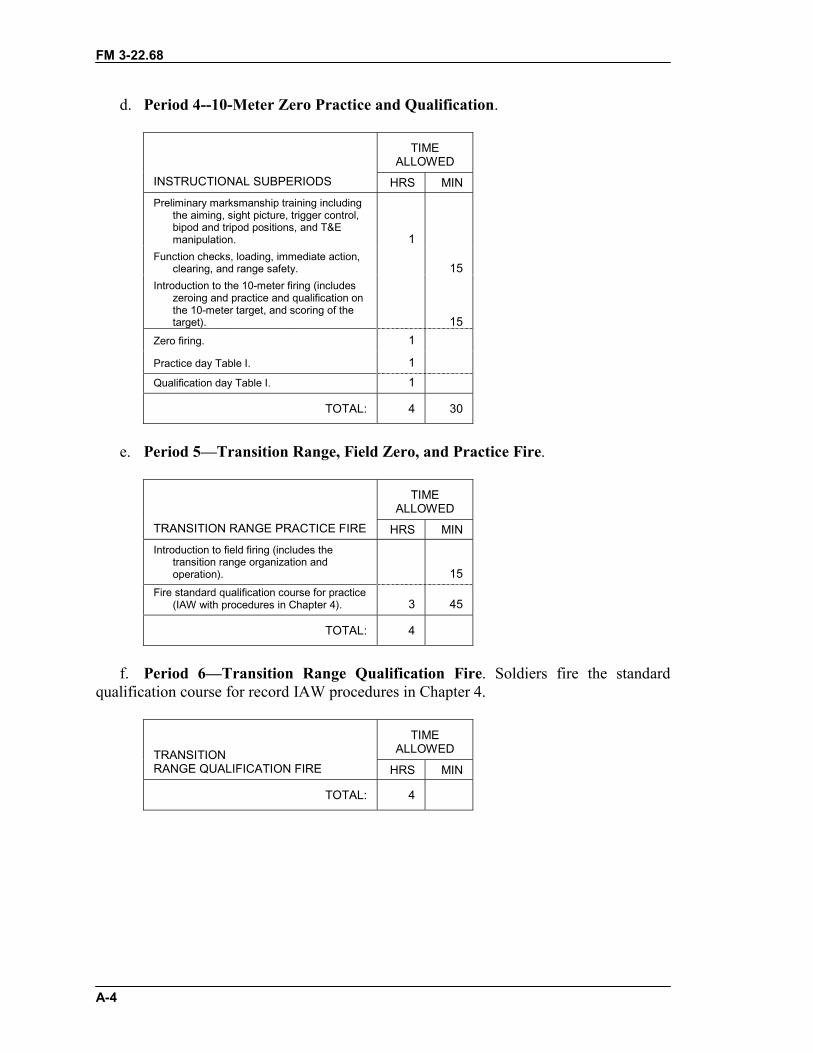
FM 3-22.68
A-4
d. Period 4--10-Meter Zero Practice and Qualification.
TIMEALLOWED
INSTRUCTIONAL SUBPERIODS HRS MINPreliminary marksmanship training including
the aiming, sight picture, trigger control,bipod and tripod positions, and T&Emanipulation. 1
Function checks, loading, immediate action,clearing, and range safety. 15
Introduction to the 10-meter firing (includeszeroing and practice and qualification onthe 10-meter target, and scoring of thetarget). 15
Zero firing. 1
Practice day Table I. 1Qualification day Table I. 1
TOTAL: 4 30
e. Period 5—Transition Range, Field Zero, and Practice Fire.
TIMEALLOWED
TRANSITION RANGE PRACTICE FIRE HRS MINIntroduction to field firing (includes the
transition range organization andoperation). 15
Fire standard qualification course for practice(IAW with procedures in Chapter 4). 3 45
TOTAL: 4
f. Period 6—Transition Range Qualification Fire. Soldiers fire the standardqualification course for record IAW procedures in Chapter 4.
TIMEALLOWEDTRANSITION
RANGE QUALIFICATION FIRE HRS MIN
TOTAL: 4

FM 3-22.68
A-5
g. Period 7—Night Zero, Instructional Fire, and Night Qualification Fire.Soldiers receive instruction on mounting, placing the night vision device into operation,boresighting, and zeroing the device once it is seated. They fire the standard night courseas Period 4, except a night vision device is mounted on the weapon.
TIMEALLOWEDNIGHT ZERO, INSTRUCTIONAL FIRE,
NIGHT QUALIFICATION FIRE HRS MIN
TOTAL: 4
A-4. HOURSThe unit training program requires a total of 23 hours and 40 minutes:
TIMEALLOWED
SUMMARY OF HOURS HRS MIN
Period 1 3Period 2 3 10Period 3 1Period 4 4 30Period 5 4Period 6 4Period 7 4
TOTAL: 23 40

FM 3-22.68
A-6
A-5. AMMUNITIONThis paragraph summarizes ammunition required for the unit training program. Leadersshould check STRAC requirements in DA Pamphlet 350-38.
a. M249 Machine Gun. See Table A-1.
TABLE ROUNDS TYPEI Practice 185 BallI Record 91 BallII Practice 182 4:1II Record 154 4:1III Practice 371 4:1III Record 154 4:1
Table A-1. M249 ammunition requirements.
b. M60 and M240B Machine Guns. See Table A-2.
TABLE ROUNDS TYPEI Practice 231 BallI Record 117 BallII Practice 236 4:1II Record 200 4:1IIIInstructional 460 4:1III Record 200 4:1
Table A-2. M60 and M240B ammunition requirements.
FM 3-22.68
B-1
APPENDIX BPROFICIENCY (PERFORMANCE) EXAMINATION
A proficiency examination determines if a soldier can perform all thetasks taught in the dry-fire training. This appendix is a guide foradministering the examination to gunners.
B-1. DRY-FIRE PROFICIENCY EXAMINATIONThe examination is a practical nonfiring exercise given during the last period ofinstruction on the machine gun before range firing. It may be held indoors if there areavailable facilities. The soldier must demonstrate techniques for the following tasks:
� General disassembly and assembly.� Placement of direction and elevation readings on the T&E mechanism.� Immediate action.� Field zeroing.� Engagement of a linear and a deep target.
B-2. CONDUCT OF THE EXAMINATIONLeaders can use the following schedule or modify it to fit their unit's training.
� Orientation, instructions, breakdown, and movement�15 minutes.� Five stations�30 minutes each.� Two breaks�10 minutes each.� Four movement periods�5 minutes each.� Total time�3 hours, 25 minutes.
B-3. STATION 1: PERFORM GENERAL DISASSEMBLY AND ASSEMBLYThis station normally has 11 setups. Each has one tripod-mounted machine gun withcover raised, bolt forward, and safety on the “F” position. This is placed on a mat to keepthe parts free of dirt.
a. The following statement should be read at this station:“DURING THIS PERIOD, YOU WILL BE ORGANIZED INTO THREEGROUPS AND REQUIRED TO DISASSEMBLE AND ASSEMBLE THEMACHINE GUN. THERE WILL BE ONE MACHINE GUN AND ONEGRADER FOR EVERY TWO GUNNERS. EACH GROUP WILL BEALLOWED EIGHT MINUTES TO COMPLETE GENERAL DISASSEMBLYAND ASSEMBLY. IF YOU HAVE ANY TROUBLE, RAISE YOUR HANDAND THE GRADER WILL ASSIST YOU. THE TWO GROUPS NOT BEINGTESTED WILL REMAIN TO THE REAR OF THE STATION WITH THEIRBACKS TOWARDS THE WORKING AREA UNTIL THEY ARE CALLED.”
b. A scoresheet, like the example in Figure B-1, should be used in grading individualperformance.
c. As each group completes this station, each grader should assemble the individualshe graded and gives them a thorough critique (6 minutes).

FM 3-22.68
B-2
________________________________________________________________________STATION 1: CHECKLISTPERFORM GENERAL DISASSEMBLY AND ASSEMBLY1. Cleared the machine gun using the procedures prescribed.2. Disassembled the machine gun as prescribed for that machine gun.
a. Removed the buttstock and buffer assembly.b. Removed the driving spring rod assembly.c. Removed the bolt and operating rod assembly. (Bolt is not separated from
operating rod)d. Removed the trigger housing assembly.e. Removed the cover assembly.f. Removed the feed tray.g. Removed the barrel assembly hand heat shield.h. Removed the handguard from the receiver.
3. Assembled the machine gun as prescribed for that machine gun.a. Replaced the handguard on the receiver.b. Replaced the barrel assembly and heat shield.c. Replaced the cover assembly and feed tray.d. Replaced the trigger assembly.e. Replaced the bolt and operating rod assembly.f. Replaced the driving spring rod assembly.g. Replaced the buttstock, pulled the bolt to the rear, closed the cover, and pulled the
trigger.4. Completed task in 8 minutes.
TASK: GENERAL DISASSEMBLY AND ASSEMBLY GO NO GO1. Cleared the machine gun using the procedures prescribed.2. Disassembled the machine gun as prescribed for that machine gun.
a. Removed the buttstock and buffer assembly.b. Removed the driving spring rod assembly.c. Removed the bolt and operating rod assembly. (Bolt is not separated
from operating rod.)d. Removed the trigger housing assemblye. Removed the cover assembly.f. Removed the feed tray.g. Removed the barrel assembly hand heat shield.h. Removed the handguard from the receiver.
3. Assembled the machine gun as prescribed for that machine gun.a. Replaced the handguard on the receiver.b. Replaced the barrel assembly with the heat shield.c. Replaced the cover assembly and feed tray.d. Replaced the trigger assembly.e. Replaced the bolt and operating rod assembly.f. Replaced the driving spring rod assembly.g. Replaced the buttstock, pulled the bolt to the rear, closed the cover, and
pulled the trigger.4. Completed task in 8 minutes.
Figure B-1. Example format for Station 1 scoresheet.
FM 3-22.68
B-3
________________________________________________________________________B-4. STATION 2: PLACE DIRECTION AND ELEVATION READINGS ONTHE T&E MECHANISMThis station normally has 11 setups. Each has one tripod-mounted machine gun completewith pintle and platform group and traversing-and-elevating mechanism.
a. For the first direction reading, the grader should ensure that the traversing slide isan even 5-mil graduation on the traversing bar. The gunner is required to place 1 to4 mils on the traversing handwheel; for example, L242. This requires the gunner to centerthe traversing mechanism before he can place the next direction reading on it. The seconddirection reading should be in the opposite direction; for example, R240. The secondelevation reading should also be a major change: +50/32 to -50/17.
b. The following statement should be read at this station:“DURING THIS PERIOD, YOU WILL BE ORGANIZED INTO THREEGROUPS AND REQUIRED TO PLACE TWO SETS OF READINGS ON THETRIPOD-MOUNTED MACHINE GUN. A GRADER WILL CHECK YOURFIRST SET OF READINGS BEFORE YOU PLACE THE SECOND SET ONTHE TRIPOD-MOUNT MACHINE GUN. YOU WILL BE ALLOWED EIGHTMINUTES AT THIS STATION. IF YOU HAVE ANY TROUBLE, RAISEYOUR HAND AND THE GRADER WILL ASSIST YOU. THE TWO GROUPSNOT BEING TESTED WILL REMAIN TO THE REAR OF THE STATIONWITH THEIR BACKS TOWARDS THE WORK AREA UNTIL THEY ARECALLED.”
c. A scoresheet, like the example in Figure B-2, should be used in grading individualperformance.
d. As each group completes this station, each grader should assemble the individualshe graded and gives them a thorough critique (6 minutes).________________________________________________________________________STATION 2: CHECKLISTPLACE DIRECTION AND ELEVATION READINGS ON THE T&EMECHANISM1. Placed first set of readings on the T&E mechanism.
a. Centered the traversing handwheel.b. Placed direction reading on T&E mechanism.c. Placed elevation reading on T&E mechanism.
2. Placed second set of readings on the T&E mechanism.a. Placed direction reading on T&E mechanism.b. Placed elevation reading on T&E mechanism.
3. Completed task in 8 minutes.
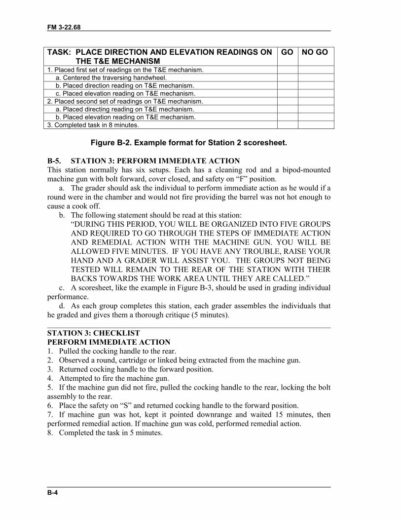
FM 3-22.68
B-4
TASK: PLACE DIRECTION AND ELEVATION READINGS ON THE T&E MECHANISM
GO NO GO
1. Placed first set of readings on the T&E mechanism.a. Centered the traversing handwheel.b. Placed direction reading on T&E mechanism.c. Placed elevation reading on T&E mechanism.
2. Placed second set of readings on T&E mechanism.a. Placed directing reading on T&E mechanism.b. Placed elevation reading on T&E mechanism.
3. Completed task in 8 minutes.
Figure B-2. Example format for Station 2 scoresheet.
B-5. STATION 3: PERFORM IMMEDIATE ACTIONThis station normally has six setups. Each has a cleaning rod and a bipod-mountedmachine gun with bolt forward, cover closed, and safety on “F” position.
a. The grader should ask the individual to perform immediate action as he would if around were in the chamber and would not fire providing the barrel was not hot enough tocause a cook off.
b. The following statement should be read at this station:“DURING THIS PERIOD, YOU WILL BE ORGANIZED INTO FIVE GROUPSAND REQUIRED TO GO THROUGH THE STEPS OF IMMEDIATE ACTIONAND REMEDIAL ACTION WITH THE MACHINE GUN. YOU WILL BEALLOWED FIVE MINUTES. IF YOU HAVE ANY TROUBLE, RAISE YOURHAND AND A GRADER WILL ASSIST YOU. THE GROUPS NOT BEINGTESTED WILL REMAIN TO THE REAR OF THE STATION WITH THEIRBACKS TOWARDS THE WORK AREA UNTIL THEY ARE CALLED.”
c. A scoresheet, like the example in Figure B-3, should be used in grading individualperformance.
d. As each group completes this station, each grader assembles the individuals thathe graded and gives them a thorough critique (5 minutes).________________________________________________________________________STATION 3: CHECKLISTPERFORM IMMEDIATE ACTION1. Pulled the cocking handle to the rear.2. Observed a round, cartridge or linked being extracted from the machine gun.3. Returned cocking handle to the forward position.4. Attempted to fire the machine gun.5. If the machine gun did not fire, pulled the cocking handle to the rear, locking the boltassembly to the rear.6. Place the safety on “S” and returned cocking handle to the forward position.7. If machine gun was hot, kept it pointed downrange and waited 15 minutes, thenperformed remedial action. If machine gun was cold, performed remedial action.8. Completed the task in 5 minutes.
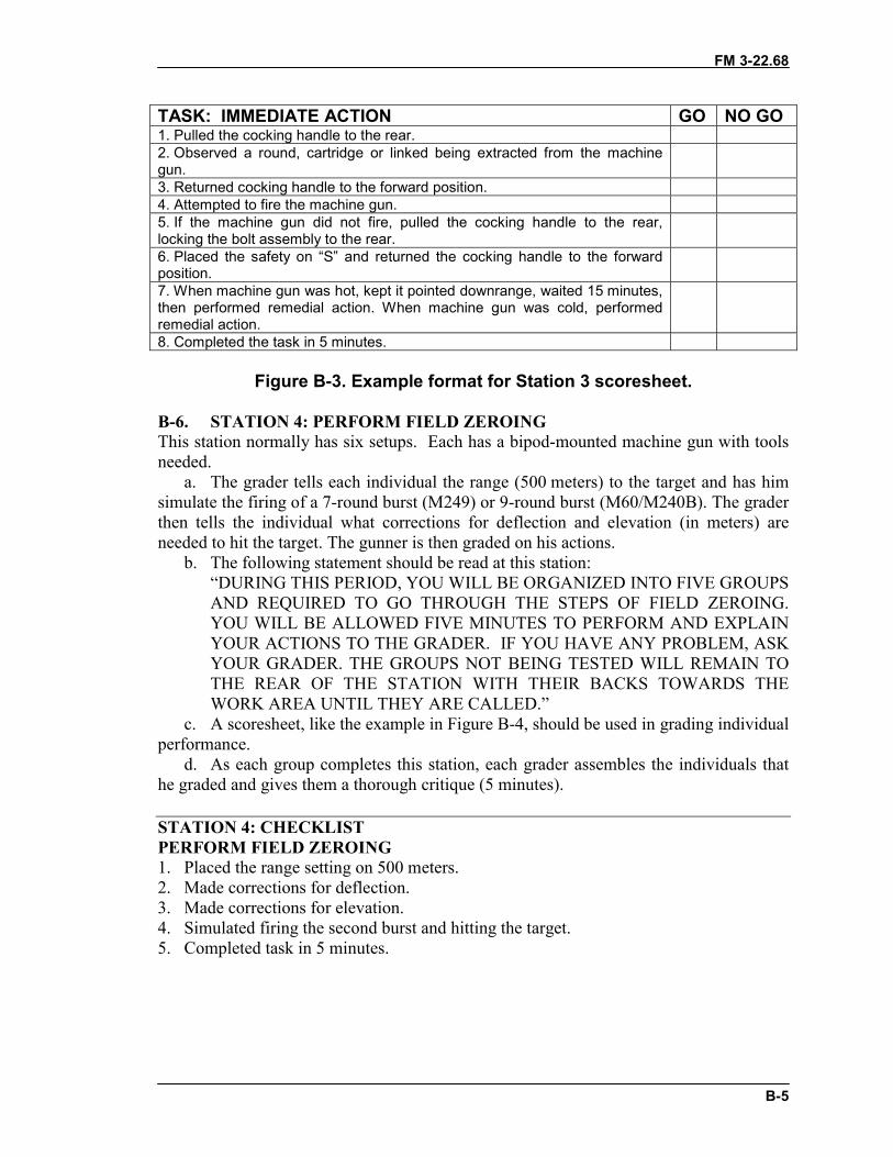
FM 3-22.68
B-5
TASK: IMMEDIATE ACTION GO NO GO1. Pulled the cocking handle to the rear.2. Observed a round, cartridge or linked being extracted from the machinegun.3. Returned cocking handle to the forward position.4. Attempted to fire the machine gun.5. If the machine gun did not fire, pulled the cocking handle to the rear,locking the bolt assembly to the rear.6. Placed the safety on “S” and returned the cocking handle to the forwardposition.7. When machine gun was hot, kept it pointed downrange, waited 15 minutes,then performed remedial action. When machine gun was cold, performedremedial action.8. Completed the task in 5 minutes.
Figure B-3. Example format for Station 3 scoresheet.
B-6. STATION 4: PERFORM FIELD ZEROINGThis station normally has six setups. Each has a bipod-mounted machine gun with toolsneeded.
a. The grader tells each individual the range (500 meters) to the target and has himsimulate the firing of a 7-round burst (M249) or 9-round burst (M60/M240B). The graderthen tells the individual what corrections for deflection and elevation (in meters) areneeded to hit the target. The gunner is then graded on his actions.
b. The following statement should be read at this station:“DURING THIS PERIOD, YOU WILL BE ORGANIZED INTO FIVE GROUPSAND REQUIRED TO GO THROUGH THE STEPS OF FIELD ZEROING.YOU WILL BE ALLOWED FIVE MINUTES TO PERFORM AND EXPLAINYOUR ACTIONS TO THE GRADER. IF YOU HAVE ANY PROBLEM, ASKYOUR GRADER. THE GROUPS NOT BEING TESTED WILL REMAIN TOTHE REAR OF THE STATION WITH THEIR BACKS TOWARDS THEWORK AREA UNTIL THEY ARE CALLED.”
c. A scoresheet, like the example in Figure B-4, should be used in grading individualperformance.
d. As each group completes this station, each grader assembles the individuals thathe graded and gives them a thorough critique (5 minutes).
STATION 4: CHECKLISTPERFORM FIELD ZEROING1. Placed the range setting on 500 meters.2. Made corrections for deflection.3. Made corrections for elevation.4. Simulated firing the second burst and hitting the target.5. Completed task in 5 minutes.
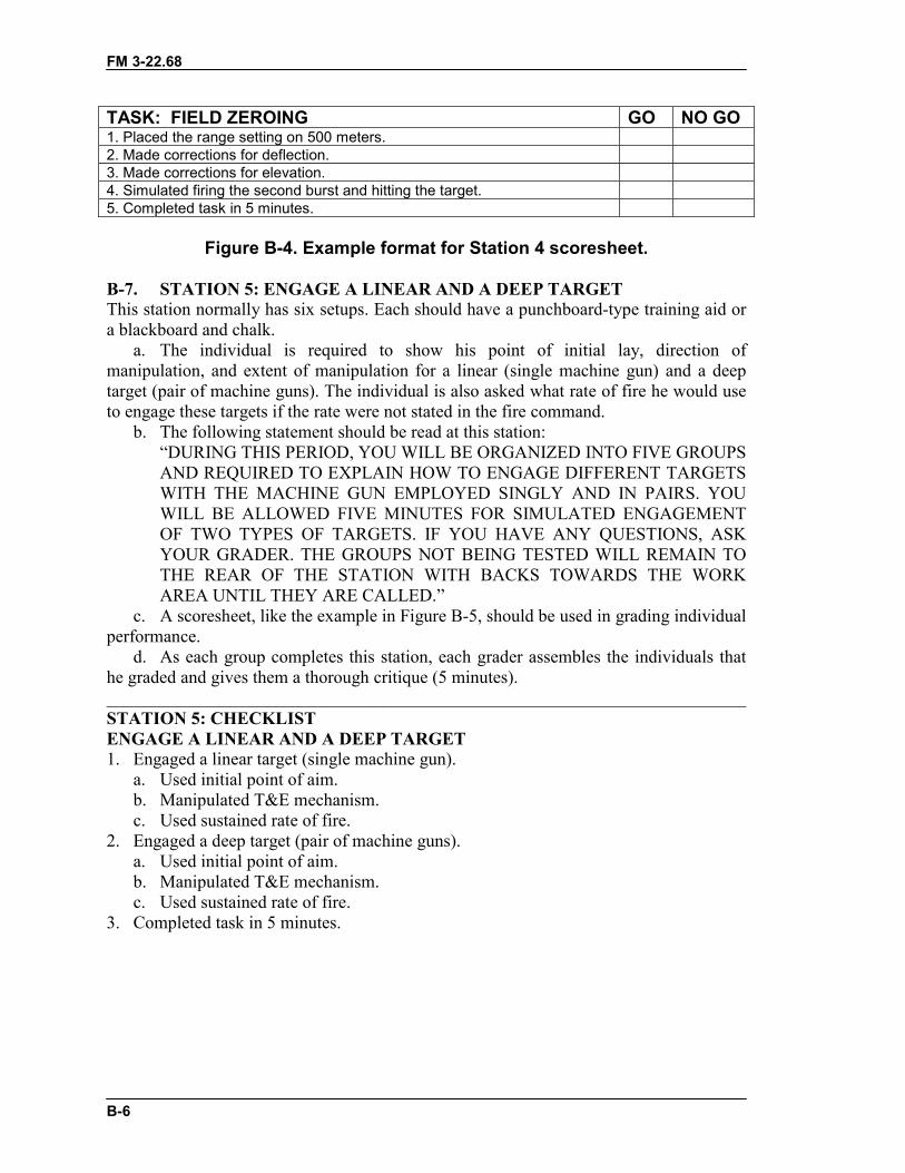
FM 3-22.68
B-6
TASK: FIELD ZEROING GO NO GO1. Placed the range setting on 500 meters.2. Made corrections for deflection.3. Made corrections for elevation.4. Simulated firing the second burst and hitting the target.5. Completed task in 5 minutes.
Figure B-4. Example format for Station 4 scoresheet.
B-7. STATION 5: ENGAGE A LINEAR AND A DEEP TARGETThis station normally has six setups. Each should have a punchboard-type training aid ora blackboard and chalk.
a. The individual is required to show his point of initial lay, direction ofmanipulation, and extent of manipulation for a linear (single machine gun) and a deeptarget (pair of machine guns). The individual is also asked what rate of fire he would useto engage these targets if the rate were not stated in the fire command.
b. The following statement should be read at this station:“DURING THIS PERIOD, YOU WILL BE ORGANIZED INTO FIVE GROUPSAND REQUIRED TO EXPLAIN HOW TO ENGAGE DIFFERENT TARGETSWITH THE MACHINE GUN EMPLOYED SINGLY AND IN PAIRS. YOUWILL BE ALLOWED FIVE MINUTES FOR SIMULATED ENGAGEMENTOF TWO TYPES OF TARGETS. IF YOU HAVE ANY QUESTIONS, ASKYOUR GRADER. THE GROUPS NOT BEING TESTED WILL REMAIN TOTHE REAR OF THE STATION WITH BACKS TOWARDS THE WORKAREA UNTIL THEY ARE CALLED.”
c. A scoresheet, like the example in Figure B-5, should be used in grading individualperformance.
d. As each group completes this station, each grader assembles the individuals thathe graded and gives them a thorough critique (5 minutes).________________________________________________________________________STATION 5: CHECKLISTENGAGE A LINEAR AND A DEEP TARGET1. Engaged a linear target (single machine gun).
a. Used initial point of aim.b. Manipulated T&E mechanism.c. Used sustained rate of fire.
2. Engaged a deep target (pair of machine guns).a. Used initial point of aim.b. Manipulated T&E mechanism.c. Used sustained rate of fire.
3. Completed task in 5 minutes.

FM 3-22.68
B-7
TASK: ENGAGE A LINEAR AND A DEEP TARGET GO NO GO1. Engaged a linear target (single machine gun).
a. Used initial point of aim.b. Manipulated T&E mechanism.c. Used sustained rate of fire.
2. Engaged a deep target (pair of machine guns).a. Used initial point of aim.b. Manipulated T&E mechanism.c. Used sustained rate of fire.
3. Completed task in 5 minutes.
Figure B-5. Example format for Station 5 scoresheet.
FM 3-22.68
C-1
APPENDIX C
AERIAL DEFENSE
This appendix describes the use of machine guns in an air defenserole, including the concept and two techniques for applying lead. Alsodiscussed are the rules of engagement and firing positions.
C-1. PASSIVE AND ACTIVE MEASURESA unit can take passive and active measures to defend itself against enemy air attack.Although volume fire is the key, there is a need to coordinate fires.
a. Passive measures are those that help the unit identify enemy aircraft before theaircraft locates the unit, make the unit difficult to locate, and make the unit lessvulnerable when attacked. The unit must develop and practice camouflage as a passivemeasure. Concealment from the air must be considered when selecting routes,transportation means, or defensive positions. The use of air guards is important to givethe unit time to react. Air guards should cover interlocking sectors of visible airspace.
b. Active measures for appropriate reactions to an air attack should be prescribed inunit SOPs. Each of the two techniques for applying lead is based on delivering a heavyvolume of fire ahead of the target. The idea is to have every soldier in the unit engage thetarget. To achieve volume fire, soldiers armed with machine guns should fire at thecyclic rate.
c. If an aircraft is attacking his position, the soldier sees the aircraft in a head-on ordiving view. To engage this aircraft, the soldier would fire slightly above the nose of theaircraft. Adjacent positions would see the aircraft in a crossing view. To engage theaircraft, these units would have to apply a proper lead. The method of applying leaddepends on the technique used.
(1) Football-Field Technique. When engaging high-performance aircraft (those flyingin excess of 200 mph), gunners should apply a one-football-field lead in front of thetarget and fire at the rapid rate until the target passes through the tracer stream. If thetarget is a low-performance aircraft, such as a helicopter, with a speed of 200 mph or less,gunners should apply half a football-field lead in front of the target, firing the cyclic rate.With all soldiers firing, a curtain of fire is formed because of slight differences in eachsoldier's estimate of the distance and lead.
(2) Reference-Point Technique. The unit leader designates terrain features asreference points. Upon spotting enemy aircraft, the leader commands, ENEMY AIR,REFERENCE POINT 1. At this time, the gunner points his weapon at reference point 1,elevates the weapon to about 45 degrees above the ground, and fires on command. Oncehe sights the target, he can make minor adjustments to align his fire on the target.
C-2. USE OF TRACERSWhen planning for air defense, the leader should consider the use of tracers so that thegunner can observe the tracer stream and better align his fire on the target. A unit mayengage an attacking aircraft without command. If an aircraft is not attacking, the unit maynot fire on it unless ordered to do so.

FM 3-22.68
C-2
C-3. FIRING POSITIONWhen firing the machine gun in an air defense role, the gunner should fire from aprotected position, if possible. When not in a fighting position, he must position theweapon so that he has some type of support. In an emergency, another soldier canprovide a firing support.
FM 3-22.68
D-1
APPENDIX DRANGE SAFETY
This appendix recommends safety precautions for the ranges describedin this manual, but it does not replace AR 385-63 or local regulations.Range safety requirements vary because of the varied requirements of thecourses of fire.
D-1. SAFETY PRECAUTIONSThe following safety precautions must be observed during all marksmanship training:
a. Display a red flag (red light for night firing) at the entrance to the range or insome other prominent location on the range during firing.
b. Always assume that weapons are loaded until they have been thoroughlyexamined and found to contain no ammunition and barrel is clear.
c. Mark firing limits with red-and-white-striped poles that are visible to all firers.d. Never place obstructions in the muzzles of weapons about to be fired.e. Keep all weapons in a prescribed area and proper safeguards when not in use.f. Do not permit smoking near ammunition, explosives, or flammables.g. Wear hearing-protection devices during firing.
D-2. RANGE PROCEDURESThe range can be a dangerous place, especially if safety procedures are not followed.Everyone must stay alert and adhere to the following precautions:
a. Before Firing.(1) Close all prescribed roadblocks and barriers, and post necessary guards.(2) Check all weapons to ensure that they are clear of ammunition and obstructions,
and that the cover-feed mechanism assemblies are up to show they are cleared.(3) Brief all personnel on the firing limits of the range and firing lanes.(4) Obtain range clearance from the installation range-control office.(5) Check the downrange area before firing to ensure that all personnel and
equipment are clear of the area.(6) Keep a complete first-aid kit on the range.(7) Locate medical personnel on or near the range where they can be contacted
quickly.(8) Have all weapons checked by an officer or noncommissioned officer to ensure
that they are operational.(9) Do not handle weapons except on command from the tower operator or the officer
in charge.(10) Draw ammunition and issue it only on command of the officer in charge. When
two or more lots of ammunition are used for firing, the officer in charge must ensure thatthe lots are separated and properly marked so that identification can be made by lotnumbers in case of an accident or malfunction.
(11) Protect all ammunition from the direct rays of the sun.(12) Do not allow anyone to move forward of the firing line without permission of the
tower operator, safety officer, or officer in charge.
FM 3-22.68
D-2
b. During Firing.(1) Immediately order “CEASE FIRE” if an unsafe condition is noted during firing.
Do not resume firing until directed to by the officer in charge.(2) During firing, all personnel on the range must be aware of the danger in moving
forward of the firing line to score their targets. Before the firing line is clear and anyoneis allowed forward, the officer in charge or the safety officer will clear all weapons.
(3) The safety officer or NCO inspects each weapon that was fired on the firing lineby making sure the bolt is locked to the rear and the safety is on. He makes sure eachbarrel is clear by running a cleaning rod through the barrel until he can see the end of therod in the receiver. He performs the safety check.
c. When Firing During Darkness.(1) Check the downrange area before firing to ensure that all personnel and
equipment are clear of the area. This is accomplished by asking three times over a publicaddress system, “IS THERE ANYONE DOWNRANGE?” Always pause each time topermit a response.
(2) Use a blinking red light in addition to the red flag. Display it at the entrance to therange or at some other prominent location.
(3) Mount two red lights on the striped poles marking the right and left limits of fire.They must be visible to all firers.
(4) Do not allow anyone to move from his position until told to do so by the officer incharge.
d. After Firing.(1) Have safety personnel inspect all weapons to ensure that they are clear, and check
to determine if the soldiers have any brass, links, or live ammunition.(2) When weapons have been cleared, keep them in a prescribed area with the bolt
forward and safety on.
FM 3-22.68
E-1
APPENDIX EEMPLOYMENT
Despite their Post-Civil War development, modern machine guns didnot exhibit their full potential in battle until World War I. Although themachine gun has changed, the role of the machine gunner has not. Themission of machine guns in battle is to deliver fires when and where theleader wants them in both the offense and defense. Machine guns rarely, ifever, have independent missions. Instead, they provide their unit withaccurate, heavy fires to accomplish the mission. This appendix providesinformation on three machine guns: the M249 light machine gun and theM60 and M240B general-purpose machine guns.
E-1. TACTICAL ORGANIZATION OF THE MACHINE GUNThe accomplishment of the mission demands an efficient machine gun crew who canfulfill all assigned missions. Each leader considers the mission and organizes machineguns to deliver firepower and fire support to any area or point needed to accomplish theassigned mission. Such organization takes time to achieve and reduces the flexibility ofthe unit.
E-2. MACHINE GUN IN THE ATTACKThe potential increase of air and ground attacks on the unit demands every possibleprecaution for maximum security while on the move. Where this situation exists, themachine gun crew must be thoroughly trained in the hasty delivery of antiaircraft fire andof counterfires against enemy ground forces. The distribution of the machine guns in theformation is critical. The machine gun crew is constantly on the alert, particularly athalts, ready to deliver fire as soon as possible. If the leader expects a halt to exceed abrief period, he carefully chooses machine gun positions to avoid unduly tiring themachine gun crew. If he expects the halt to extend for a long period, he can have themachine gun crew take up positions in support of the unit. They cover the direction fromwhich he expects enemy activity as well as the direction the unit came from. He selectspositions that permit the delivery of fire in the most probable direction of attack, such asinto valleys, draws, ridges, and spurs. He chooses positions that offer obstructed fire.
a. Machine Gun in the Offense.(1) General Discussion. Successful offensive operations result from the employment
of fire and maneuver. Each is essential and greatly depends upon the other. Without thesupport of covering fires, maneuvering in the presence of enemy fire can result indisastrous losses. Covering fires, especially those that provide fire superiority, allowmaneuvering in the offense. However, fire superiority alone rarely wins battles. Theprimary objective of the offense is to advance, occupy, and hold the enemy position.
(2) Machine Gun. The machine gun delivers an accurate, high-volume rate of fire onfairly large areas in a brief time. It is a great power to have on any offensive operation.When accurately placed on the enemy position, machine gun fires secure the essentialelement of fire superiority for the duration of the firing. Troops advancing in the attackshould take full advantage of this period to maneuver to a favorable position from which
FM 3-22.68
E-2
to facilitate the last push against the enemy. In addition to casualties, machine gun firedestroys the enemy's confidence and neutralizes his [actions in the?] defense.
(3) Early Entry. The early entry of machine guns in the offense is, with rareexceptions, highly desirable. Their continued action up to the moment of the assaultenhances the probability of success. One desirable feature for employment of machineguns in the offense requires a proper handling of the ammunition for each machine gun.The other feature is to determine the actions of the machine gun crew to handle theirweapon on the battlefield in order to deliver fire with the objective to support themaneuver unit at the time it is needed, regardless of physical difficulties encountered
(a) The machine guns seldom accompany the maneuver element. The gun’s primarymission is to provide covering fire. The machine guns are only employed with themaneuver element when the area or zone of action assigned to the assault or company istoo narrow to permit proper control of the guns. The machine guns are then moved withthe unit and readied to employ on order from the leader and in the direction needing thesupporting fire.
(b) Where the area or zone of action is too wide to allow proper coverage by themachine guns, the unit is assigned additional machine guns or personnel from within thebattalion to permit the unit to accomplish its assigned mission. The machine guns areassigned a zone or a sector to cover and they move with the maneuver element.
(c) Under certain terrain conditions and for proper control, the machine guns movewith the unit and are assigned a zone or sector to cover.
(d) When machine guns move with the unit undertaking the assault, the unit brings itsmachine guns to provide additional firepower. These weapons are fired either from thebipod or in an assault mode, from the hip or underarm position. They target enemyautomatic weapons anywhere on the unit's objective. Once the enemy’s automaticweapons have been destroyed, or if there are none, the gunners distribute their fire overtheir assigned zone or sector. In terms of engagement ranges, the machine gun in theassault engages within 300 meters of its target and frequently at point blank ranges.
c. Machine Gun in a Base-of-Fire Element. Machine guns organic to the companycan help battalion machine guns lay the base of fire. In this case, the leader positions andcontrols the fires of all machine guns in the element. Machine gun targets include keyenemy weapons or groups of enemy targets either on the objective or attempting toreinforce or counterattack. In terms of engagement ranges, machine guns in the base-of-fire element may find themselves firing at targets within 800 meters of the target. Theseranges are simply a practical average. The nature of the terrain and desire to achievesome standoff, leads the leader to the correct tactical positioning of the base-of-fireelement.
E-3. MACHINE GUN IN THE DEFENSEMachine gun fire is distributed in width and depth in a defensive position. The leader canuse machine guns to subject the enemy to increasingly devastating fire from the initialphases of his attack, and to neutralize any partial successes the enemy might attain bydelivering intense fires in support of counterattacks. The machine gun’s tremendousfirepower is what enables the unit to hold ground. This is what makes them the backboneor framework of the defense.
FM 3-22.68
E-3
a. The units’ defense centers around the platoon's machine guns. The platoon leadersites the rifle squad to protect the machine guns against the assault of a dismountedenemy formation. The machine gun provides the requisite range and volume of fire tocover the squad front in the defense.
b. The primary requirement of a suitable machine gun position in the defense is thatthe machine gun be able to accomplish its specific missions. Secondarily, the positionshould be accessible and afford cover and concealment. Machine guns are sited to protectthe front, flanks, and rear of occupied portions of the defensive position, and to bemutually supporting. Attacking troops usually seek easily traveled ground that providescover from fire. This is not to say that they will avoid marshes, rough grounds, woodedareas, or any other type of terrain. Every machine gun should have three positions:primary, alternate, and supplementary. All of these positions should be chosen by theleader to ensure his sector is covered and that the machine guns are protected ontheir flanks.
c. The leader sites his machine gun to cover the entire sector or to overlap sectorswith the other machine gun. The engagement range of a leader's weapon may extendfrom the last 300 meters where the enemy begins his assault to point-blank range.Machine gun targets include enemy automatic weapons and command and controlelements.
E-4. MACHINE GUN ON A SECURITY MISSIONSecurity includes all command measures to protect against surprise, observation, andannoyance by the enemy. The principal security measures against ground forces includeemployment of security patrols and detachments covering the front flanks and rear of theunits’ most vulnerable areas. The composition and strength of these detachments dependson the size of the main body, its mission, and the nature of the opposition expected. Thepresence of machine guns with security detachments augments their firepower toeffectively delay, attack, and defend, by virtue of their inherent firepower. When themachine guns are used as part of the security detachments in battalion trains or larger, theproportion of machine guns in such a detachment varies according to the situation. Themain mission of the machine gun is to protect and defend through both defensive andoffensive missions. For defense, the unit’s main mission is to position the machine gunsthroughout the assigned area. For offense, the second mission, after a successful delayagainst an enemy attack, the unit expands its security outpost as needed to preventanother enemy attack.
FM 3-22.68
F-1
APPENDIX FTRAINING AIDS AND DEVICES
Training aids and devices must be included in a marksmanshipprogram. This appendix lists those that units can make from materialsmost units have on-hand.
F-1. TRAINING DEVICES AND EXERCISESThe marksmanship training devices in this appendix are available to aid in sustainmenttraining when used with the appropriate training strategies. These devices are beneficialwhen ammunition is limited for training or practice. Some training devices are complexand costly, but others are relatively simple and cheap to make. Devices and aids can beused alone or in combination. Individuals or squads can sustain or practice basicmarksmanship skills and fundamentals with devices and aids.
F-2. FIRST SIGHTING AND AIMING EXERCISEThe purpose of the first sighting and aiming exercise is to teach the correct alignment ofthe sights on a target.
a. Equipment Needed:One�sighting bar complete for each machine gun crew.One�sighting target that measures 1 inch X 2 inches X 48 inches long. Thesighting target is secured 5 1/2 inches away from one end (it should bemoveable). The eyepiece is secured on the other end. The peep sight issecured 20 1/2 inches from the sighting target and 22 inches from the eyepiece(Figure F-1).
Figure F-1. Sighting bar.
b. Conduct. The instructor shows a sighting bar to the machine gun crews, pointsout its parts, and explains its use as follows:
(1) The sighting bar is used to assist in detecting small errors and in explaining themto the crews undergoing instruction.
FM 3-22.68
F-2
(2) The front and rear sights on the sighting bar represent enlarged machine gunsights.
(3) The gunner looks through the eyepiece in such a position that he sees the sights inexactly the same alignment as the instructor does. Although there is no eyepiece on themachine gun, the use of an eyepiece on the sighting bar assists the gunners in learninghow to align the sights properly when using the machine gun.
(4) The attachment of the removable target to the end of the sighting bar provides asimple method of readily aligning the sights on the target.
(5) Using a blackboard or a chart, the instructor explains and illustrates the correctsight alignment.
(6) A gunner from each crew adjusts the sights of the sighting bar and movable targetto correctly align the sights on the target.
F-3. SECOND SIGHTING AND AIMING EXERCISEThe purpose of the second sighting and aiming exercise is to apply the preceding lessonto actual alignment of the machine gun sights on a target 25 meters away.
a. Equipment Needed:One�Machine gun.One�Basic machine gun target placed 25 meters away, with the reverse(blank) side showing.One�Sighting target, 24 inches long 1 inch X 1 inch, a 3-inch square piece ofwood painted black with a small 1/4-inch hole in the center (Figure F-2).
Figure F-2. Sighting target.
b. Conduct. The instructor takes a normal position behind the machine gun, keepinghis body and hands clear of the gun so that the eye is in the correct position for aiming.
(1) The gunner takes a position near enough to observe the instructor.(2) The assistant gunner stands near the instructor to transmit signals to the
ammunition bearer.(3) The ammunition bearer is provided with the 3-inch sighting target and is posted as
the marker at the blank target, which is 25 meters away from the gun.(4) The instructor, through improvising signals transmitted through the signalman,
directs the marker to move the sighting target until it correctly aligns with the sights, andthen commands: HOLD.
(5) The marker complies, holding the sighting target in place on the blank target. Thegunner and assistant gunner then look through the sights.
(6) The instructor explains that, in aiming, the gunner’s eye should first focus on thetarget, to ensure that he is aiming at the proper target. His eye then focuses on the top of
FM 3-22.68
F-3
the front sight, to ensure that the line-of-sight established passes through the center of thepeep sight and over the top of the center of the front sight.
(7) After the gunner and assistant gunner look through the sight, the instructor directsthe marker (ammunition bearer) to move the sighting target out of alignment. He thenrequires the gunner to direct the marker to move the sighting target until it is in correctalignment with the sights.
(8) The instructor checks the alignment made by the gunner and points out any errors.When the instructor believes the gunner is proficient, the assistant gunner begins hisexercise.
F-4. THIRD SIGHTING AND AIMING EXERCISEThe purpose of the third sighting and aiming exercise is to show the importance ofuniform and correct aiming and to instill in the gunners a sense of exactness. Thisexercise can be used to check the consistency of the aiming and placement of athree-round shot group in a dry-fire environment.
a. Equipment Needed:One�Machine gun.One�Basic machine gun target placed at a distance of 25 meters away with thereverse (blank) side showing.One�Sighting target (24 inches long 1 inch X 1 inch, a 3-inch square piece ofwood painted black and a small 1/4-inch hole in the center) (Figure F-2).
b. Conduct. The instructor takes a normal position behind the machine gun, keepinghis body and hands clear of the gun so that the eye is in the correct position for aiming.
(1) The gunner takes a position near the instructor to observe.(2) The assistant gunner stands near the instructor to transmit signals to the
ammunition bearer.(3) The ammunition bearer is provided with a 3-inch sighting target and is posted as
the marker at the blank target, which is 25 meters away from the gun.(4) The instructor, improvising signals, transmits through the signalman to direct the
marker to move the sighting target until it is in correct alignment with the sights and thencommands: MARK.
(5) The marker complies, holding the sighting target in place on the blank target. Themarker marks the position by inserting the tip of a pencil through the 1/4-inch hole in thecenter of the target. The marker marks the first dot with a number 1, second with a 2 andthe third with a 3, ensuring the marker moves the target after every mark. All three dotsshould fit inside a 4-cm circle.
(6) The instructor explains that, in aiming, the gunner’s eye should first be focused onthe target to ascertain that he is aiming at the proper target. His eye is then focused on thetop of the front sight to ensure the line of sighting established is a line through the centerof the peep sight and over the top of the center of the front sight.
(7) The gunner and assistant gunner, without touching the gun, repeat the operationuntil three dots have been made and numbered.
(8) The instructor now explains the errors noted in the three sight alignments and theprobable shape of the shot group formed by joining the three dots. Repeat as many timesas needed until the gunner and assistant gunner can put seven rounds inside a 4-cm circle.The grader marks the first dot with a number 1, the second with a number 2 and the third
FM 3-22.68
F-4
with a number 3. He makes sure the grader moves the target after every mark. When theinstructor believes the gunner is proficient, the assistant gunner begins his exercise.
(9) The marker traces the three dots on a sheet of paper and connects them with lines.He writes the gunner’s name at the bottom of the sheet and gives the paper to the squadleader.
F-5. MACHINE GUN T&E MANIPULATION DRILLSThe purpose of these exercises is to teach and instill confidence in the gunner in properlyusing his T&E. These exercises are conducted on a 25-meter line.
a. Equipment Needed:One�Machine gun.One�4-foot X 8-foot sheet of plywood. Paint the plywood white with black ruledlines of 1/8-inch width horizontally and vertically. The horizontal lines are2 inches apart, starting 1 inch from the top and the bottom. The vertical lines are3 inches apart, with 1 inch on either side.
(1) Label the horizontal lines starting from the top with 1, 3 and so on skipping everyother line. Label the vertical lines along the middle horizontal line starting at the left; forexample, A, B, C and so on (Figure F-3).
(2) When using the night vision sight, cut out a 4-cm-square circle from everyfour squares across and down. The squares or circles can be cut in any order the unitleader desires.
(3) Set up the machine 25 meters away from the target. Center the machine gun onthe target.
Figure F-3. Manipulator for T&E drills.
FM 3-22.68
F-5
b. Conduct.(1) The gunner is given the command to aim at vertical line B and horizontal line 4.
The next command is RIGHT 150 mils; ADD 50 mils. The instructor then asks thegunner where he is aiming.
(2) Lay on the horizontal line 15 and vertical line O. The next command is, LEFT100 mils; ADD 10 mils. The instructor then asks the gunner where he is aiming now.
(3) The leader or instructor can have as many of these types of questions set up, untilhe feels the gunner is proficient at this task.
F-6. TRAVERSE AND SEARCH EXERCISEThe purpose of the traverse and search exercise is to teach the gunner how to aim andpoint on a silhouette target and maintain that aim while the target is moving.
a. Equipment Needed:One�Machine gun.One�Basic machine gun target placed at a distance of 25 meters away with thereverse (blank) side showing.One�Marking silhouette measures 1 inch X 1/2 inch X 22 inches long (wood).One�F-type silhouette (reduced by half its size) measuring 7 1/2 inches long X3 3/4 high (Chapter 4).
b. Conduct. The instructor shows the target to the machine gun crews. He points outits parts and explains its use as follows:
(1) The gunner takes a normal position behind the machine gun. The gunner isrequired to aim at a prescribed point on the silhouette target and to maintain that aimduring the uniform movement of the target.
(2) The assistant gunner takes a normal position next to the gunner. The assistantgunner assists the gunner in maintaining the point of aim.
(3) The ammunition bearer is located 25 meters away behind the basic machine guntarget with the target. The bearer moves the target back and fourth, up and down in anydirection he wants. The movement should be consistent and not uniform, so that thegunner and assistant gunner can get proper training. The speed that the ammunitionbearer moves depends on the instructor.
(4) The instructor watches the gunner and determines if the gunner or assistantgunner is properly doing the exercise by telling the ammunition bearer to stop and hold.He informs the gunner or assistant gunner to stand.
(5) The instructor positions himself behind the gun and looks through the sights tosee where the gunner or assistant gunner was aiming. The instructor now explains theerrors noted. When the instructor believes the gunner is proficient, the assistant gunnerbegins his exercise.
F-7. ENGAGEMENT SKILLS TRAINERThe engagement skills trainer (EST) 2000 (Figure F-4, page F-6) is a home station,indoor, multipurpose, multilane, small arms simulator. The EST augments and substitutesindividual, crew, and static-squad collective training. Using projected imagery and laser-light technologies, the EST 2000 provides weaponry that simulates the same physical,functional, operational characteristics, and capabilities of service weapons. Weaponry forthe EST 2000 includes the M16A2 rifle, M4 carbine, M9 pistol, M249 automatic
FM 3-22.68
F-6
rifle/light machine gun, M60, M240B and M2 machine guns, MK 19 grenade machinegun, M136 AT4, M1200 shotgun, and M203 grenade launcher.
Figure F-4. EST 2000.
a. The EST 2000 is a modular system with an operational size of 35 feet by 35 feetby 8 feet high for a 10-lane system. Training programs include standard Army courses offire, “shoot-don’t shoot” decision training, and static-squad or element collectivedefensive training for infantry, scouts, engineers, military police, and CS or CSS. Basis ofissue is one 15-lane EST 2,000 for each OSUT or BCT battalion supporting Initial EntryTraining (IET) and one 10-lane EST 2,000 for each brigade-size element for Active andReserve Component units for sustainment training.
b. The following tables (Tables F-1, F-2, and F-3) show the capabilities andlimitations for each training program:

FM 3-22.68
F-7
MARKSMANSHIP TRAINING PROGRAM209 marksmanship exercises, from zeroing through record-fire courses.Capabilities LimitationsTrain and sustain M16A2 rifle skills. No qualification.
No weather effects.Train and sustain M4 carbine skills. No qualification.
No weather effects.Train and sustain shotgun skills. No qualification.
No nonlethal munitions training.Train and sustain M9 pistol skills. No qualification.
No weather effects.Train and sustain light MG skills. No maneuver training.Train and sustain AR skills. No maneuver training.Train and sustain MMG skills. No maneuver training.Train and sustain M2 HB MG skills. No maneuver training.Train and sustain M203 GL skills. No maneuver training.
No nonlethal munitions.Train and sustain MK 19 grenade MG skills. No maneuver training.Train antiarmor weapons employment. No maneuver training.
Table F-1. Marksmanship training capabilities and limitations.
COLLECTIVE TRAINING PROGRAM178 squad tactical exercises against varying enemy targets, in terrain that varies fromwoodlands, desert, urban, and mountains that are typical of terrain found throughoutthe world.Capabilities LimitationsTrain and sustain defensive operations. No offensive operations.Train and sustain overwatch operations. Nontactical interaction.Train and sustain passage of lines. Overwatch only.Train and sustain ambush operations. Limited eye points.
Restricted interaction with on-screenCGI forces.
NOTE: No effects of weather and firing position distances under squad leader and fire-team leader control.
Table F-2. Collective training capabilities and limitations.
“SHOOT-DON'T SHOOT” TRAINING PROGRAM40 “shoot-don't shoot” judgmental exercises.Capabilities LimitationsTrain and test rules of engagement. No shoot back.
No nonlethal training mode.Train target selection under stress. No shoot back.Train target engagement under stress. No shoot back.Train verbal skills to deescalate. No direct adversary reactions.
Table F-3. “Shoot-don't shoot” training capabilities and limitations.
FM 3-22.68
F-8
c. The EST trains many skills, but it is not intended to replace live qualification orMILES force-on-force tactical training. Its many capabilities are clearly definable, but itslimitations preclude total elimination of training ammunition resources. Training on theEST is planned to save ammunition resources, both at the assistant gunner and secondaryfirer positions and in peripheral training exercises such as protective mask and night-firesmall-arms training. The EST 2000 enhances moving target training exercises.Sometimes shortages of range facilities or environmentally safe range resources preventtraining in night, moving, and protective mask. The EST 2000 is the only three-modetraining device capable of conducting realistic range operations while sustaining STRACstandards for individual weapons training, sustaining collective tactical skills andtraining, and sustaining judgmental engagements for the peace-keeping role of today’sforces.
FM 3-22.68
G-1
APPENDIX GADVANCED OPTICS AND LASERS
The newest systems greatly increase the night firing accuracy of allcrew-served machine guns. They primarily enhance the gunner’s ability toengage targets with great effectiveness to ranges of or beyond1,000 meters. This appendix describes the AN/PAQ-4C, AN/PEQ-2A, lasersystems. It also describes the AN/PAS-13 thermal sight and the M145(MGO) telescope. Information for mounting, boresighting, and zeroingprocedures for each weapon is also given.
Section I. ZERO PROCEDURESAn established day/night advanced marksmanship program equipped with trainingstrategies and proposed qualification standards has been developed. Before beginning anight marksmanship program, soldiers must qualify on their assigned weapons duringdaylight conditions as outlined in the previous chapters of this manual and TMs.However, this appendix implements the new night qualification standards to complimentcurrent Army training strategies. Commanders should follow these training strategies andabide by the qualification standards set forth to the best of their abilities. Although somecourses of fire at first may seem redundant or inappropriate, numerous tests show thatthese training strategies work, and the qualification standards are achievable, if thestrategy is followed.
G-1. BORE LIGHTThe bore light is an accurate means of zeroing weapons and the most aided visionequipment without the use of ammunition. Time and effort are applied to ensure a preciseboresight, which in turn saves time and ammunition. Table G-1 outlines weapon/aidedvision device combinations that can be zeroed using the bore light with theM249/M60/M240B weapons. With optics, a 25-meter zero must follow boresighting. Theprecise boresighting of a laser allows the soldier to directly engage targets without a25-meter zero.
M249 M60 M240B
MGO X X XAN/PAQ-4C X X XAN/PEQ-2A X X XAN/PAS-13 X X X
Table G-1. Weapon/aided vision device combinations.
a. Intent. Align the bore of the weapon to the optic, laser, or iron sight being fired toreduce or eliminate the time and ammunition it currently requires to live fire zero.
b. Special Instructions. Here are some special instructions the gunner shouldfollow:
� Zero the bore light.� Use only approved 10-meter offsets from Picatinny Arsenal (noted on offset).
FM 3-22.68
G-2
� Ensure the proper 10-meter offset is used for the weapon configuration.� Ensure boresighting is conducted 10 meters from the end of the barrel.� Ensure weapon and offset is stabilized or the boresight will not be accurate.� Ensure filters for aiming lasers are installed to reduce blooming.
b. Observables. The gunner should do the following:� Confirm that the bore light spins on itself when zeroed at 10 meters.� Boresight using the official and proper offsets only.� Confirm that the weapon and offset are not moving during the boresighting
procedure.� Confirm that the bore light is centered on the circle of the offset.� Confirm that the aiming device is aimed at the center of the crosshair on the
offset.
DANGERSPERMANENT INJURY COULD OCCUR WHEN DOINGTHE FOLLOWING:1. STARE INTO THE VISIBLE LASER BEAM.2. LOOK INTO THE VISIBLE LASER BEAM THROUGH
BINOCULARS OR TELESCOPE.3. POINT THE VISIBLE LASER BEAM AT MIRROR-LIKE
SURFACES.4. SHINE THE VISIBLE LASER BEAM INTO OTHER
INDIVIDUALS’ EYES.
WARNINGS1. Make sure the weapon is CLEAR and on SAFE
before using the bore light.2. Ensure that the bolt is locked in the forward
position.3. When rotating the bore light to zero it, ensure the
mandrel is turning counterclockwise (from thegunner’s point of view) to avoid loosening the borelight from the mandrel.
G-2. CONCEPTBoresighting is a simple procedure that can save time and ammunition only if theprocedures outlined in this section are strictly followed. The bore light is a visible laserthat is aligned with the barrel of the designated weapon. Then using a 10-meter offset,boresight the weapon with any optic, laser, or iron sight that you are assigned to fire.This procedure is accomplished by simply ensuring that the visible laser of the bore lightis in line with the barrel by zeroing the bore light to the weapon, and then placing thevisible laser of the bore light in a designated spot on the 10-meter offset. Once thisprocedure is accomplished, simply move the aiming point of the aiming device to thecross hair on the 10-meter offset. The weapon system is now boresighted and you are
FM 3-22.68
G-3
ready to engage targets or conduct a 25-meter zero. With optics, such as the MGO, TWS,and PVS-4, the bore light will put you on paper at 25 meters, thus reducing time andammunition trying to locate rounds during the 25-meter zeroing. With lasers, the borelight allows you to boresight and then engage targets, eliminating the 25-meter zeroingprocedures all together.
G-3. ZERO of BORE LIGHT TO WEAPONBefore boresighting the weapon system, make sure the bore light is first zeroed to theweapon. Take a flashlight and shine it through the barrel of the weapon and at 10 metersmark the spot that the flashlight is shining on. Then, without moving the weapon, fire oneround. The impact of the round and the mark made with the flashlight should be thesame. This procedure is the same principle used when zeroing the bore light to theweapon. This procedure is nothing more than aligning the visible laser with the barrel ofthe weapon, which would then hit the same area that the flashlight hit.
G-4. STABILIZEStabilization of the weapon is crucial. The weapon can be stabilized on a tripod or usingthe bipod as a field-expedient method. The weapon does not have to be perfectly levelwith the ground when boresighting the weapon. Every barrel is different; therefore, withevery weapon, steps (d) through (f) must be done to ensure that the bore light is zeroed tothat barrel. If the bore light is zeroed, then go directly to the boresighting procedures.
a. Attach the 5.56-mm or 7.62-mm mandrel to the bore light.b. Insert the mandrel into the muzzle of the weapon. The bore light is seated
properly when no further travel of the mandrel into the muzzle is permitted and themandrel spins freely.
c. Stabilize the weapon so that it will not move. The commands of Start Point andHalf Turn are given to ensure clear communication between the soldier by the weaponand the soldier by the offset.
(1) 10 Meters. 10 meters can be measured with the 10-meter cord that comes with thebore light or simply pace off eleven paces.
(2) Zeroing Mark. The zeroing mark (Figure G-1) is nothing more than a small dotdrawn on a piece of paper, tree bark, or the bore light reference point on the 10-meteroffset.
CAUTIONDo not over adjust the laser at soldiers.
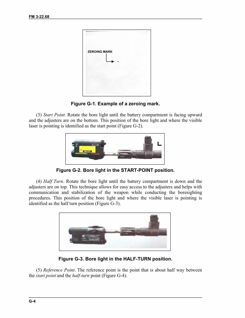
FM 3-22.68
G-4
Figure G-1. Example of a zeroing mark.
(3) Start Point. Rotate the bore light until the battery compartment is facing upwardand the adjusters are on the bottom. This position of the bore light and where the visiblelaser is pointing is identified as the start point (Figure G-2).
Figure G-2. Bore light in the START-POINT position.
(4) Half Turn. Rotate the bore light until the battery compartment is down and theadjusters are on top. This technique allows for easy access to the adjusters and helps withcommunication and stabilization of the weapon while conducting the boresightingprocedures. This position of the bore light and where the visible laser is pointing isidentified as the half turn position (Figure G-3).
Figure G-3. Bore light in the HALF-TURN position.
(5) Reference Point. The reference point is the point that is about half way betweenthe start point and the half-turn point (Figure G-4).
ZEROING MARKZEROING MARK
FM 3-22.68
G-5
Figure G-4. Example of a start point, half-turn point, and reference point.
d. Turn the bore light on and spin it until it is in the start point position. Get azeroing mark and mark a dot on it. Place the zeroing mark about 10 meters from the endof the barrel so that the visible laser strikes the zeroing mark.
e. Slowly rotate the bore light 360 degrees, while watching the visible laser made bythe bore light. If the visible laser stops on the zeroing mark, the bore light is zeroed to theweapon.
f. If the bore light does not stop on the zeroing mark, then elevation and windageadjustments must be made to the bore light.
g. From the start point, realign the zeroing mark with the visible laser and rotate thebore light 180 degrees into the half turn position. Then identify the reference point. Usingthe adjusters on the bore light move the visible laser to the reference point. Rotate thebore light back to the start point; move the zeroing mark to the visible laser. If the visiblelaser cannot be located once the bore light has been spun into the half turn position, startthis procedure again at 2 meters instead of 10 meters. Once the visible laser is adjusted tothe reference point at 2 meters, then start the procedure again at 10 meters.
h. Repeat step g until the visible laser spins on itself.
G-5. BORESIGHT TARGET OFFSETAppendix H shows the most current 10-meter boresight target offsets. The 10-meterboresight offset grids are 1-centimeter squares, unlike the 25-meter zero targets.Some boresight target offsets are not available at this print. For more information, contactthe infantry proponent at C co, 2/29 IN at Fort Benning, GA. Stability of the weapon iscrucial in boresighting. Place the weapon in the Bolt Forward position duringboresighting procedures. Do not cant the weapon left or right during this process. Twosoldiers (a firer and a target holder) are required to properly boresight a weapon.
X
HALF TURN
Reference point
FM 3-22.68
G-6
a. Firer. The firer’s primary duty is to zero the bore light and make all adjustmentson the aided vision device being used.
b. Target Holder. The target holder secures the 10-meter boresight target straightup and down 10 meters from the bore light and directs the firer in making the necessaryadjustments to the aiming device. The target holder must wear night vision goggles whenboresighting infrared aiming lasers.
NOTE: Weapon stabilization is crucial, orientation is irrelevant.
Section II. AN/PAQ-4C AIMING LIGHTThe AN/PAQ-4 aiming light projects an infrared laser beam, which cannot be seen withthe naked eye but can be seen with night vision devices. This aiming light works with theAN/PVS-7B/C/D goggles and AN/PVS-14. The AN/PAQ-4C mounts on variousweapons with mounting brackets and adapters.
G-6. EQUIPMENT DATA AND DESCRIPTIONThe AN/PAQ-4 aiming light (Figure G-5) is activated by rotating the ON/OFF switchlever or the button on the optional cable switch. Either switch connects power from twoAA batteries to an internal electronic circuit, which produces the infrared laser. Internallenses focus the infrared light into a narrow beam. Rotating the mechanical adjusters withclick detents controls the direction of the beam. These adjusters are used to zero theaiming light to the weapon. Once zeroed to the weapon, the aiming light projects thebeam along the line of fire of the weapon. The optical baffle prevents off-axis viewing ofthe aiming light beam by the enemy.
a. Data. The AN/PAQ-4 aiming light includes the following equipment data:Optics: 100 percent parallax free, anti-reflective coated lens system.Length (sight): 14 centimeters (5.5 inches)Weight: 164 grams (5.78 ounces)Height: 3 centimeters (1.2 inches)Width: 6.5 centimeters (2.5 inches)Range: Beyond 600 meters. (Actual range depends on light level and night
vision device used for observation.)Battery life: 100-hour operating (ON) time for AA batteries in temperatures
above 0 degrees centigrade (32 degrees Fahrenheit); 36-hours fortemperatures below 0 degrees centigrade (32 degrees Fahrenheit).
FM 3-22.68
G-7
Figure G-5. AN/PAQ-4 aiming light.
c. M249 Machine Gun.(1) Mounting Procedures. The gunner uses the AN/PVS-4 mounting bracket when
mounting the AN/PAQ-4 on the M249 machine gun.
CAUTIONWhen mounting an AN/PAQ-4 to the mounting bracket,make sure that the hole for the screw in the AN/PAQ-4 isaligned and flush against the bracket screw. If not, thescrew will strip the threads in the screw hole of theAN/PAQ-4 and prevent use with the M249.
(a) Install the AN/PVS-4 mounting bracket by first placing the mounting bracket ontop of the feed cover mechanism assembly so that the two forked ends are secured aroundthe headless pins. Next, remove the screw cover behind the rear sight assembly, andscrew the bracket knob in until it is tight.
(b) Install the bracket adapter (Figure G-6).
Figure G-6. Bracket adapter.
FM 3-22.68
G-8
(c) Attach the AN/PAQ-4 on the bracket adapter (Figure G-7).
Figure G-7. Attaching bracket adapter to aiming light.
(d) Attach the AN/PAQ-4 to the AN/PVS-4 mounting bracket by first positioning theAN/PAQ-4 on top of the bracket so the spacer of the AN/PAQ-4 is aligned with themounting knob of the bracket. Then, turn the mounting knob clockwise until theAN/PAQ-4 is tight.
WARNINGDo not store the AN/PAQ-4 with batteries installed.
(2) Dismounting Procedures.(a) Detach the AN/PAQ-4 from the AN/PVS-4 mounting bracket. Turn the mounting
knob counterclockwise until the AN/PAQ-4 is loose. Remove the AN/PAQ-4 and spacerfrom the bracket.
(b) Remove the spacer from the AN/PAQ-4.(c) Remove the AN/PVS-4 mounting bracket. Unscrew the bracket knob until the
rear of the bracket is loose. Replace the screw cover behind the rear sight assembly.Remove the two forked ends from the headless pins and lift up on the mounting bracketto remove it from the feed cover mechanism assembly.
c. M60 Machine Gun.(1) Mounting Procedures. The gunner uses the AN/PVS-4 mounting bracket when
mounting the AN/PAQ-4 on the M60 machine gun.
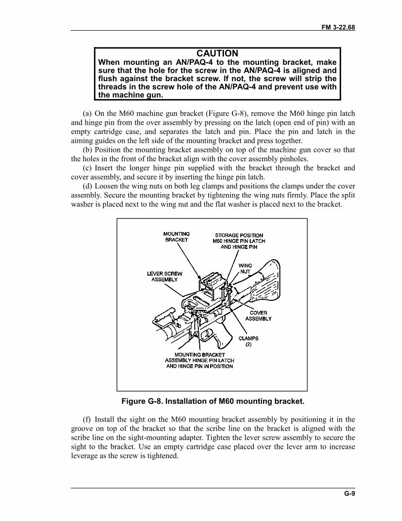
FM 3-22.68
G-9
CAUTIONWhen mounting an AN/PAQ-4 to the mounting bracket, makesure that the hole for the screw in the AN/PAQ-4 is aligned andflush against the bracket screw. If not, the screw will strip thethreads in the screw hole of the AN/PAQ-4 and prevent use withthe machine gun.
(a) On the M60 machine gun bracket (Figure G-8), remove the M60 hinge pin latchand hinge pin from the over assembly by pressing on the latch (open end of pin) with anempty cartridge case, and separates the latch and pin. Place the pin and latch in theaiming guides on the left side of the mounting bracket and press together.
(b) Position the mounting bracket assembly on top of the machine gun cover so thatthe holes in the front of the bracket align with the cover assembly pinholes.
(c) Insert the longer hinge pin supplied with the bracket through the bracket andcover assembly, and secure it by inserting the hinge pin latch.
(d) Loosen the wing nuts on both leg clamps and positions the clamps under the coverassembly. Secure the mounting bracket by tightening the wing nuts firmly. Place the splitwasher is placed next to the wing nut and the flat washer is placed next to the bracket.
Figure G-8. Installation of M60 mounting bracket.
(f) Install the sight on the M60 mounting bracket assembly by positioning it in thegroove on top of the bracket so that the scribe line on the bracket is aligned with thescribe line on the sight-mounting adapter. Tighten the lever screw assembly to secure thesight to the bracket. Use an empty cartridge case placed over the lever arm to increaseleverage as the screw is tightened.
FM 3-22.68
G-10
(2) Dismounting Procedures.(a) Unscrew the lever screw assembly by turning it counterclockwise and remove the
AN/PAQ-4 from the mounting bracket. Use an empty cartridge case placed over the leverarm for increased leverage if necessary.
(b) Loosen the wing nuts on both leg clamps.(c) Push down on the longer hinge pin latch with an empty cartridge case and remove
the hinge pin and latch.(d) Remove the mounting bracket from the machine gun.(e) Remove the M60 hinge pin and latch from the left side of the bracket by pushing
on the hinge pin latch and pulling out the hinge pin.(f) Replace the M60 hinge pin and latch.(g) Remove the batteries when storing the sight.d. M240B Machine Gun.(1) Mounting Procedures. Before zeroing and qualifying with the AN/PAQ-4, the
gunner must mount the sight onto his weapon. The M240B machine gun has a rail mountalready attached to the cover assembly.
(a) Install the sight on the M240B rail mount by loosening the mounting knob locatedon the left side.
(b) Position the sight in a slot on the rail mount. Any slot can be used as long as themount does not hang over the edge of the rail.
(c) Hand tighten the knob (clockwise) on the mount until a clicking noise is heard(two clicks).
(d) Places the sight in the same slot after zeroing to ensure that the sight retains itszero.
WARNINGDo not store the AN/PAQ-4 with batteries installed.
(2) Dismounting Procedures. Loosen the mounting knob on the left side of thebracket, then lift up on the sight to remove it from the M240B machine gun.
(a) Adjust the bore light, if necessary. Move the target to a distance of 2 meters. Markthe location of the laser dot. Slowly rotate the bore light one half turn. Note the newlocation of the laser dot. Adjust the windage and elevation until the laser dot moveshalfway back to its original location. Continue the procedure until the laser dot remainsstationary (or spins upon itself within 1 centimeter) when the bore light is rotated. Movethe target to a distance of 10 meters and recheck the boresight.
(b) Boresight the AN/PAQ-4 to the weapon. Select the target (boresight offset) forthe appropriate weapon and the AN/PAQ-4. Position the weapon so the bore light strikesthe small dot on the boresight target. Zero the AN/PAQ-4 by turning both windage andelevation knobs (for the pointer and illuminator) fully clockwise until they stop. Rotatecounterclockwise three turns and align the white dot on the adjuster with the center of thefront adjuster flange (Figure G-9).

FM 3-22.68
G-11
Figure G-9. Adjuster alignment.
G-7. BORESIGHT AND ZERO PROCEDURESThe following procedures are used to boresight and zero the M249, M60, and M240Bmachine guns using the AN/PAQ-4C aiming light.
a. Boresight. Check the alignment of the bore light.(1) Place the appropriate mandrel with the bore light attached in the muzzle of the
weapon.(2) Turn on the bore light so that the laser dot strikes the target (offset) 10 meters
away.(3) Slowly rotate the bore light one-half turn (180 degrees) while watching the dot
made by the laser on the target area.(4) If the dot remains stationary, the laser is boresighted. Go to step 3 and use the
appropriate boresight target for the weapon being boresighted.(5) If the dot rotates in a circle, adjust the windage, elevation, or both until the dot
remains stationary or rotates on itself no more than 1 cm. Go to step 2.b. 25-Meter Zero. The gunner chooses the appropriate strike zone from
TM 11-5855-309-12&P, and draws it on the 25-meter zero target. He follows theprocedures above and zeroes the weapon with the AN/PAQ-4. He fires a total of threerounds (one at a time) before triangulating the shot group. Once the weapon is zeroed onthe 25-meter zero range, the gunner follows the procedures outlined below for fieldzeroing to obtain an accurate zero.
c. Field Zero. If the adjustment screws are turned too far, they will break. If thelaser is side-mounted, the elevation and windage knobs will switch roles.
(1) Assume a good prone bipod-supported position. Fire a seven-round burst at thetarget. Note the burst pattern on the ground in relation to the target.
(2) Correct for windage (if rounds are impacting to the right or left of the target).Note that each click of the windage knob sight moves the group on the target mil (1/2 milequals 6 inches at 300 meters or 10 inches at 500 meters).
(3) Correct for elevation (if rounds are impacting over or short of the target).After making corrections on the sight, fire a confirming burst. If the target is not hit withthe confirming burst, repeat the above procedures. Treat each subsequent burst as if itwere the initial burst.
FM 3-22.68
G-12
(2) Prepare the sight for field zeroing and check the sight. The preferred range is300 meters.
G-8. TRAINING STRATEGIESTwo training strategies have been devised to adequately train soldiers in the use of theinfrared aiming laser devices. The night initial training strategy is used for soldiers whohave little or no previous experience with night vision goggles or with units beginning anight training program. The night sustainment training strategy is for soldiers who arefamiliar with night vision goggles and with units who have already implemented a nighttraining program. The night initial training strategy is conducted over a two- to three-daytime frame and consists of the following:
a. Day 1.(1) Night Vision Goggles Training With Terrain Walk When Firing Aiming Lasers.
Soldiers are given in-depth instruction on the proper use and fit of night vision goggles,to include characteristics and capabilities, maintenance, and mounting procedures. Atnight, soldiers conduct a terrain walk to become more familiar and build confidence usingthe night vision goggles.
(2) Aiming Device Training. Soldiers receive familiarization training on the aimingdevice. This training covers operation and characteristics, maintenance procedures, andmounting procedures.
(3) Fundamentals of Firing. This includes body position, foxhole, and prone. Soldiersreview and practice firing positions and fundamentals of marksmanship and any changesthat occur when using this aiming device.
b. Day 2 to 3.(1) Weapon and Equipment. Inspect the weapon and aiming device to ensure the
aiming device is mounted securely to the weapon. A review of clearing or misfireprocedures is important. Let the soldiers use dummy rounds to practice correctingmalfunctions with their eyes closed or during limited visibility.
(2) Boresight Aiming Device to Weapon. Each soldier boresights the weapon andaiming device at a range of 10 meters. If a bore light is not available, then 25-meter zerothe weapon and sight by using the specified zeroing procedure for that weapon/sightcombination. For course of fire, refer to Table 4-4 in Chapter 4 for a description of theaiming laser and AN/PVS-4 firing table. MGO and TWS will fire the day qualificationtable. c. Field Fire I. Perform dry-fire exercise with no ammunition:
(1) Assume a stable, prone firing position. Fire the weapon maintaining sightalignment and sight picture. Pull the trigger correctly by pulling straight to the rear andreleasing the trigger. Pull the trigger to the rear and say to yourself, “fire a burst ofseven.” After the word “seven,” let go of the trigger.
(2) Apply correct traversing and searching techniques. Traversing means moving themuzzle of the weapon to the left or to the right to distribute fire laterally. Shift theshoulder slightly to the right or left for minor changes. For major changes, move theelbows and align the body directly behind the weapon. Searching means moving themuzzle of the weapon up or down to distribute fire in depth. To make changes inelevation, move the elbows closer or farther apart.
FM 3-22.68
G-13
(3) The following targets are used for field fire I:� 200-meter target single E-type silhouettes.� 300-meter target single E-type silhouettes.� 400-meter target double E-type silhouettes.� 500-meter target double E-type silhouettes.� 200-meter single E-type and 500-meter double E-type silhouettes.� 300-meter single E-type and 400-meter double E-type silhouettes.� 200-meter single E-type silhouettes.� 400-meter double E-type silhouettes.� 600-meter double E-type silhouettes.
d. Field Fire II. Perform a timed, dry-fire exercise on a transition range. Thisfamiliarizes the gunner with acquiring targets on a timed exercise. It also allows thesoldier and the point safety time to make any corrections on-sight, or the body positionand grip before the qualification table.
(1) Assume a stable, prone firing position. Fire the weapon maintaining sightalignment and sight picture. Pull the trigger correctly. Pull straight to the rear and release.Pull the trigger to the rear and say to yourself, “fire a burst of seven.” After the word“seven,” let go of the trigger.
(2) Apply correct traversing and searching techniques. Traversing means moving themuzzle of the weapon to the left or to the right to distribute fire laterally. Shift theshoulder slightly to the right or left for minor changes. For major changes, move theelbows and align the body directly behind the weapon. Searching means moving themuzzle of the weapon up or down to distribute fire in depth. To make changes inelevation move the elbows closer or farther apart.
(b) The following targets are used for field fire II:� 200-meter target single E-type silhouettes (15 seconds).� 300-meter target single E-type silhouettes (20 seconds).� 400-meter target double E-type silhouettes (25 seconds).� 500-meter target double E-type silhouettes (30 seconds).� 200-meter single E-type silhouettes (40 seconds).� 500-meter double E-type silhouettes (40 seconds).� 300-meter single E-type silhouettes (35 seconds).� 400-meter double E-type silhouettes (35 seconds).� 200-meter single E-type silhouettes (50 seconds).� 400-meter double E-type silhouettes (50 seconds).� 600-meter double E-type silhouettes (50 seconds).
e. Night Record Qualification. Perform live-fire exercises with ammunition.Engage targets on a transition range timed. This exercise measures the gunner's ability toengage targets during a timed exercise (154 rounds of A064 4x1 mix 5.56-mm linkedM249, 154 rounds of A131 4x1 mix 7.62-mm linked M60 and M240B):
(1) Assume a stable, prone firing position. Fire the weapon maintaining sightalignment and sight picture. Pull the trigger correctly. Pull straight to the rear and release.Pull the trigger to the rear and say to yourself, “fire a burst of seven.” After the word“seven,” let go of the trigger.
(2) Apply correct traversing and searching techniques. Traversing means moving themuzzle of the weapon to the left or to the right to distribute fire laterally. Shift the
FM 3-22.68
G-14
shoulder slightly to the right or left for minor changes. For major changes, move theelbows and align the body directly behind the weapon. Searching means moving themuzzle of the weapon up or down to distribute fire in depth. To make changes inelevation move the elbows closer or farther apart.
(3) Use observation and adjustment of fire. Observe machine gun fire by noting thestrike of the projectiles in the target area. When firing the bipod-mounted gun, adjust fireby changing body position.
(4) Apply the adjusted aiming point method. The adjusted aiming point method is ameans of rapidly and accurately adjusting fires without making sight adjustment. If theinitial burst misses the target, select a new aiming point on the ground. The aiming pointshould be the same distance from the target as the initial burst’s center of impact.
(5) The following targets are used for night record qualification with the AN/PVS-4and the aiming lasers. TWS and MGO will fire the day record fire table:
� 200-meter target single E-type silhouettes (10 seconds).� 300-meter target single E-type silhouettes (15 seconds).� 400-meter target double E-type silhouettes (15 seconds).� 500-meter target double E-type silhouettes (25 seconds).� 200-meter single E-type silhouettes (35 seconds).� 500-meter double E-type silhouettes (35 seconds).� 300-meter single E-type silhouettes (30 seconds).� 400-meter double E-type silhouettes (30 seconds).� 200-meter single E-type silhouettes (45 seconds).� 400-meter double E-type silhouettes (45 seconds).� 600-meter double E-type silhouettes (45 seconds).
Section III. AN/PEQ-2A TARGET POINTER/ILLUMINATOR/AIMING LIGHT
The AN/PEQ-2A target pointer/illuminator/aiming light (TPIAL) (Figure G-11) is aClass IIIB laser that emits a highly collimated beam of infrared light for precise aiming ofthe weapon as well as a separate infrared illuminating beam with adjustable focus. Asafety block is provided for training purposes (blue side), which limits the operator fromselecting the high power modes (black side).
G-9. DESCRIPTIONThis paragraph gives a description of the AN/PEQ-2A along with its accessories(Figure G-10). This paragraph also describes how to install and operate the AN/PEQ-2A.The TPIAL projects an infrared laser beam that cannot be seen with the eye but can beseen with night vision devices. It is capable of projecting a much wider infraredilluminating beam from an integral illuminator. The TPIAL works with night visiongoggles and mounts on various weapons with mounting brackets and adapters. Leadersuse the AN/PEQ-2A in the hand-held mode to illuminate and designate targets.
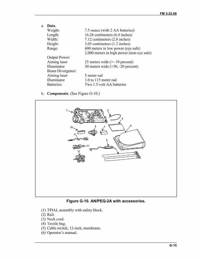
FM 3-22.68
G-15
a. Data.Weight: 7.5 ounce (with 2 AA batteries)Length: 16.26 centimeters (6.4 inches)Width: 7.12 centimeters (2.8 inches)Height: 3.05 centimeters (1.2 inches)Range: 600 meters in low power (eye safe)
2,000 meters in high power (non-eye safe)Output Power:Aiming laser 25 meters wide (+- 10 percent)Illuminator 30 meters wide (+50, -20 percent)Beam Divergence:Aiming laser 5 meter radIlluminator 1.0 to 115 meter radBatteries: Two 1.5-volt AA batteries
b. Components. (See Figure G-10.)
Figure G-10. AN/PEQ-2A with accessories.
(1) TPIAL assembly with safety block.(2) Rail.(3) Neck cord.(4) Textile bag.(5) Cable switch, 12-inch, membrane.(6) Operator’s manual.
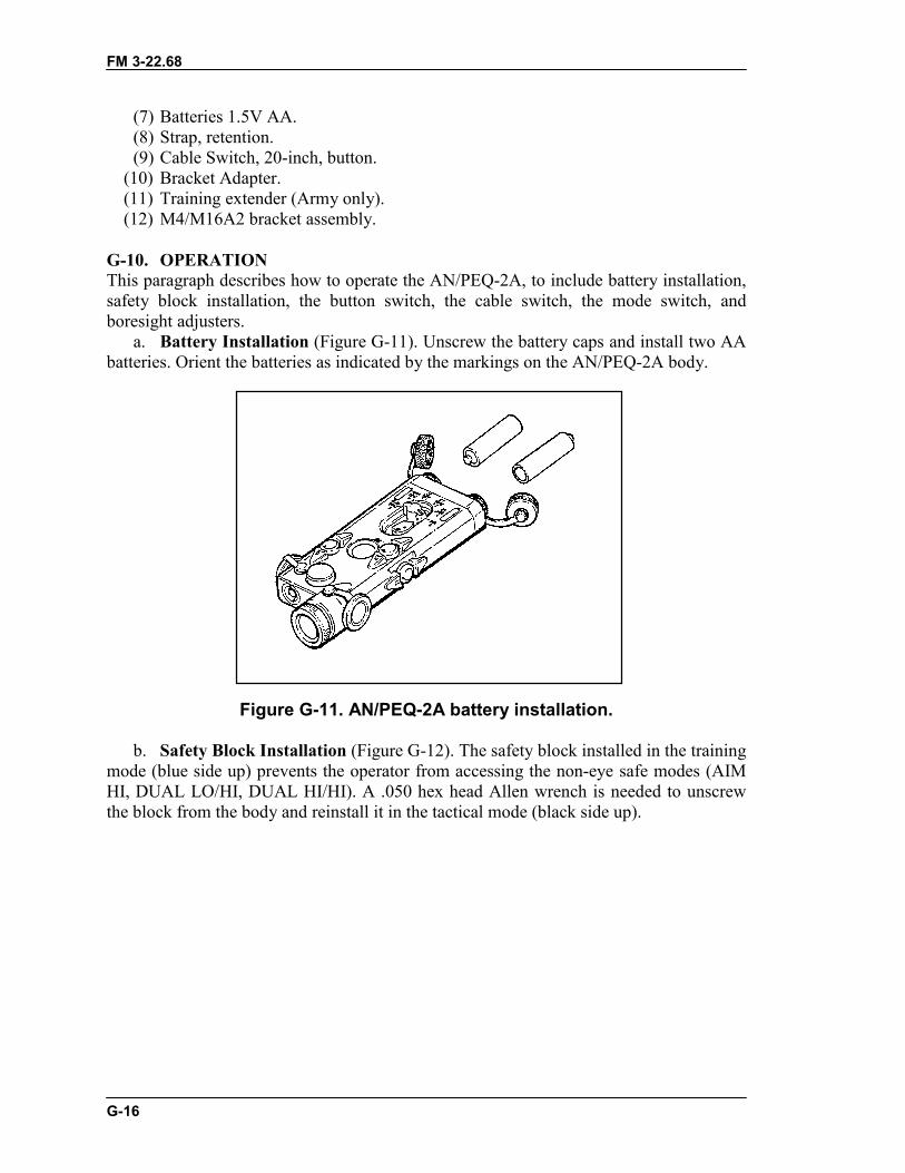
FM 3-22.68
G-16
(7) Batteries 1.5V AA.(8) Strap, retention.(9) Cable Switch, 20-inch, button.
(10) Bracket Adapter.(11) Training extender (Army only).(12) M4/M16A2 bracket assembly.
G-10. OPERATIONThis paragraph describes how to operate the AN/PEQ-2A, to include battery installation,safety block installation, the button switch, the cable switch, the mode switch, andboresight adjusters.
a. Battery Installation (Figure G-11). Unscrew the battery caps and install two AAbatteries. Orient the batteries as indicated by the markings on the AN/PEQ-2A body.
Figure G-11. AN/PEQ-2A battery installation.
b. Safety Block Installation (Figure G-12). The safety block installed in the trainingmode (blue side up) prevents the operator from accessing the non-eye safe modes (AIMHI, DUAL LO/HI, DUAL HI/HI). A .050 hex head Allen wrench is needed to unscrewthe block from the body and reinstall it in the tactical mode (black side up).
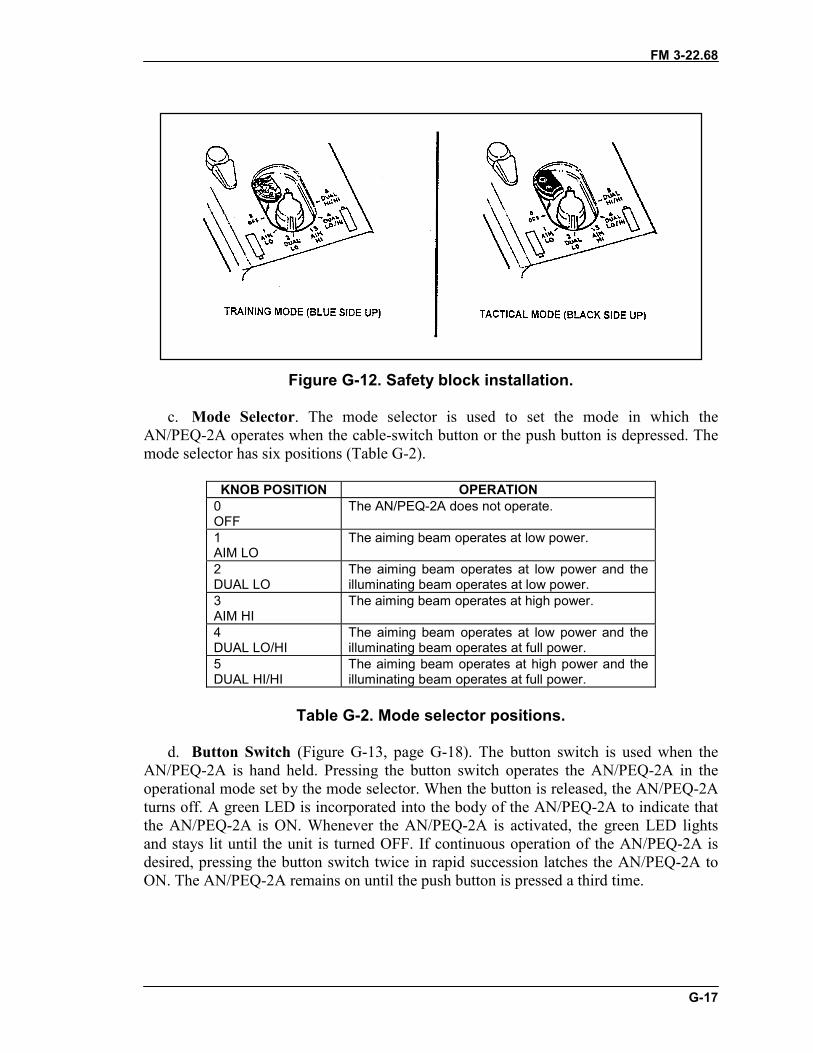
FM 3-22.68
G-17
Figure G-12. Safety block installation.
c. Mode Selector. The mode selector is used to set the mode in which theAN/PEQ-2A operates when the cable-switch button or the push button is depressed. Themode selector has six positions (Table G-2).
KNOB POSITION OPERATION0OFF
The AN/PEQ-2A does not operate.
1AIM LO
The aiming beam operates at low power.
2DUAL LO
The aiming beam operates at low power and theilluminating beam operates at low power.
3AIM HI
The aiming beam operates at high power.
4DUAL LO/HI
The aiming beam operates at low power and theilluminating beam operates at full power.
5DUAL HI/HI
The aiming beam operates at high power and theilluminating beam operates at full power.
Table G-2. Mode selector positions.
d. Button Switch (Figure G-13, page G-18). The button switch is used when theAN/PEQ-2A is hand held. Pressing the button switch operates the AN/PEQ-2A in theoperational mode set by the mode selector. When the button is released, the AN/PEQ-2Aturns off. A green LED is incorporated into the body of the AN/PEQ-2A to indicate thatthe AN/PEQ-2A is ON. Whenever the AN/PEQ-2A is activated, the green LED lightsand stays lit until the unit is turned OFF. If continuous operation of the AN/PEQ-2A isdesired, pressing the button switch twice in rapid succession latches the AN/PEQ-2A toON. The AN/PEQ-2A remains on until the push button is pressed a third time.
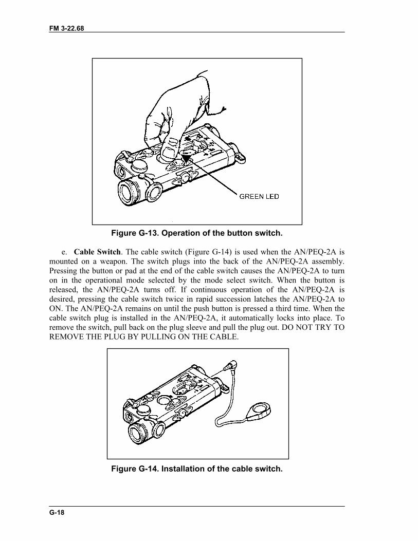
FM 3-22.68
G-18
Figure G-13. Operation of the button switch.
e. Cable Switch. The cable switch (Figure G-14) is used when the AN/PEQ-2A ismounted on a weapon. The switch plugs into the back of the AN/PEQ-2A assembly.Pressing the button or pad at the end of the cable switch causes the AN/PEQ-2A to turnon in the operational mode selected by the mode select switch. When the button isreleased, the AN/PEQ-2A turns off. If continuous operation of the AN/PEQ-2A isdesired, pressing the cable switch twice in rapid succession latches the AN/PEQ-2A toON. The AN/PEQ-2A remains on until the push button is pressed a third time. When thecable switch plug is installed in the AN/PEQ-2A, it automatically locks into place. Toremove the switch, pull back on the plug sleeve and pull the plug out. DO NOT TRY TOREMOVE THE PLUG BY PULLING ON THE CABLE.
Figure G-14. Installation of the cable switch.
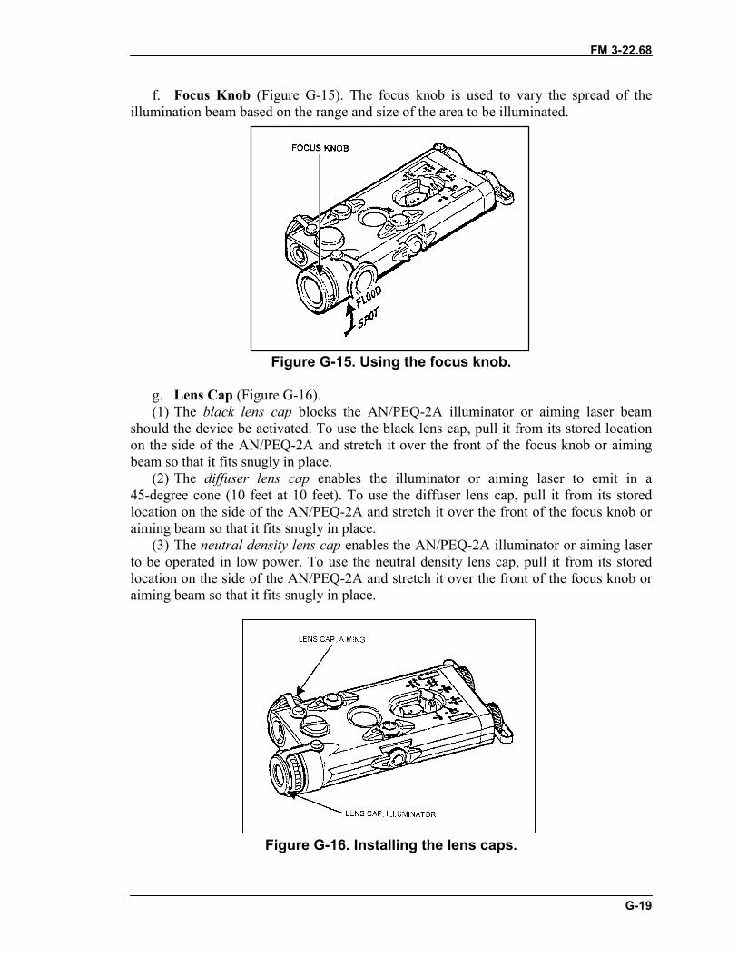
FM 3-22.68
G-19
f. Focus Knob (Figure G-15). The focus knob is used to vary the spread of theillumination beam based on the range and size of the area to be illuminated.
Figure G-15. Using the focus knob.
g. Lens Cap (Figure G-16).(1) The black lens cap blocks the AN/PEQ-2A illuminator or aiming laser beam
should the device be activated. To use the black lens cap, pull it from its stored locationon the side of the AN/PEQ-2A and stretch it over the front of the focus knob or aimingbeam so that it fits snugly in place.
(2) The diffuser lens cap enables the illuminator or aiming laser to emit in a45-degree cone (10 feet at 10 feet). To use the diffuser lens cap, pull it from its storedlocation on the side of the AN/PEQ-2A and stretch it over the front of the focus knob oraiming beam so that it fits snugly in place.
(3) The neutral density lens cap enables the AN/PEQ-2A illuminator or aiming laserto be operated in low power. To use the neutral density lens cap, pull it from its storedlocation on the side of the AN/PEQ-2A and stretch it over the front of the focus knob oraiming beam so that it fits snugly in place.
Figure G-16. Installing the lens caps.
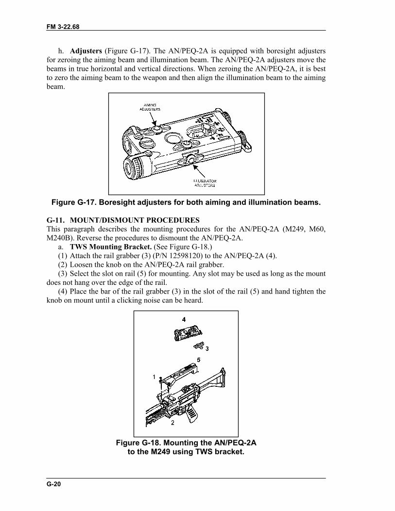
FM 3-22.68
G-20
h. Adjusters (Figure G-17). The AN/PEQ-2A is equipped with boresight adjustersfor zeroing the aiming beam and illumination beam. The AN/PEQ-2A adjusters move thebeams in true horizontal and vertical directions. When zeroing the AN/PEQ-2A, it is bestto zero the aiming beam to the weapon and then align the illumination beam to the aimingbeam.
Figure G-17. Boresight adjusters for both aiming and illumination beams.
G-11. MOUNT/DISMOUNT PROCEDURESThis paragraph describes the mounting procedures for the AN/PEQ-2A (M249, M60,M240B). Reverse the procedures to dismount the AN/PEQ-2A.
a. TWS Mounting Bracket. (See Figure G-18.)(1) Attach the rail grabber (3) (P/N 12598120) to the AN/PEQ-2A (4).(2) Loosen the knob on the AN/PEQ-2A rail grabber.(3) Select the slot on rail (5) for mounting. Any slot may be used as long as the mount
does not hang over the edge of the rail.(4) Place the bar of the rail grabber (3) in the slot of the rail (5) and hand tighten the
knob on mount until a clicking noise can be heard.
Figure G-18. Mounting the AN/PEQ-2Ato the M249 using TWS bracket.
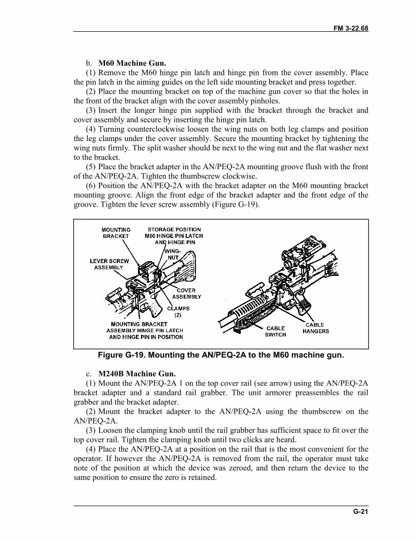
FM 3-22.68
G-21
b. M60 Machine Gun.(1) Remove the M60 hinge pin latch and hinge pin from the cover assembly. Place
the pin latch in the aiming guides on the left side mounting bracket and press together.(2) Place the mounting bracket on top of the machine gun cover so that the holes in
the front of the bracket align with the cover assembly pinholes.(3) Insert the longer hinge pin supplied with the bracket through the bracket and
cover assembly and secure by inserting the hinge pin latch.(4) Turning counterclockwise loosen the wing nuts on both leg clamps and position
the leg clamps under the cover assembly. Secure the mounting bracket by tightening thewing nuts firmly. The split washer should be next to the wing nut and the flat washer nextto the bracket.
(5) Place the bracket adapter in the AN/PEQ-2A mounting groove flush with the frontof the AN/PEQ-2A. Tighten the thumbscrew clockwise.
(6) Position the AN/PEQ-2A with the bracket adapter on the M60 mounting bracketmounting groove. Align the front edge of the bracket adapter and the front edge of thegroove. Tighten the lever screw assembly (Figure G-19).
Figure G-19. Mounting the AN/PEQ-2A to the M60 machine gun.
c. M240B Machine Gun.(1) Mount the AN/PEQ-2A 1 on the top cover rail (see arrow) using the AN/PEQ-2A
bracket adapter and a standard rail grabber. The unit armorer preassembles the railgrabber and the bracket adapter.
(2) Mount the bracket adapter to the AN/PEQ-2A using the thumbscrew on theAN/PEQ-2A.
(3) Loosen the clamping knob until the rail grabber has sufficient space to fit over thetop cover rail. Tighten the clamping knob until two clicks are heard.
(4) Place the AN/PEQ-2A at a position on the rail that is the most convenient for theoperator. If however the AN/PEQ-2A is removed from the rail, the operator must takenote of the position at which the device was zeroed, and then return the device to thesame position to ensure the zero is retained.
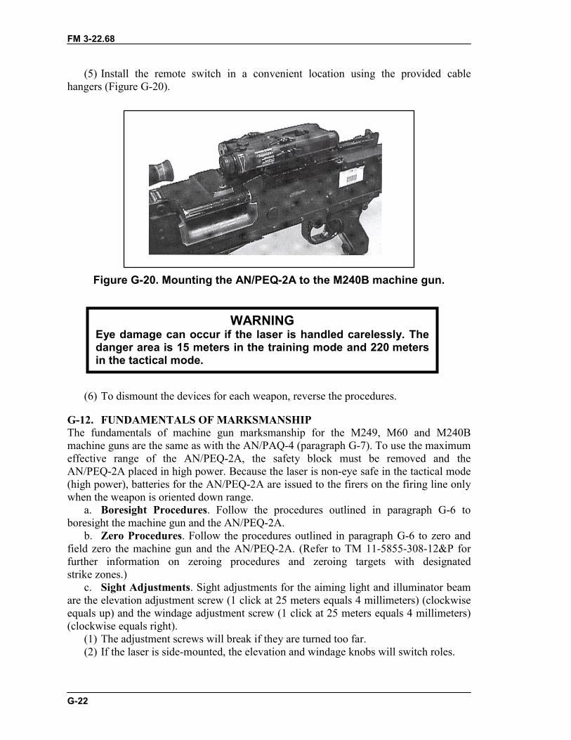
FM 3-22.68
G-22
(5) Install the remote switch in a convenient location using the provided cablehangers (Figure G-20).
Figure G-20. Mounting the AN/PEQ-2A to the M240B machine gun.
(6) To dismount the devices for each weapon, reverse the procedures.
G-12. FUNDAMENTALS OF MARKSMANSHIPThe fundamentals of machine gun marksmanship for the M249, M60 and M240Bmachine guns are the same as with the AN/PAQ-4 (paragraph G-7). To use the maximumeffective range of the AN/PEQ-2A, the safety block must be removed and theAN/PEQ-2A placed in high power. Because the laser is non-eye safe in the tactical mode(high power), batteries for the AN/PEQ-2A are issued to the firers on the firing line onlywhen the weapon is oriented down range.
a. Boresight Procedures. Follow the procedures outlined in paragraph G-6 toboresight the machine gun and the AN/PEQ-2A.
b. Zero Procedures. Follow the procedures outlined in paragraph G-6 to zero andfield zero the machine gun and the AN/PEQ-2A. (Refer to TM 11-5855-308-12&P forfurther information on zeroing procedures and zeroing targets with designatedstrike zones.)
c. Sight Adjustments. Sight adjustments for the aiming light and illuminator beamare the elevation adjustment screw (1 click at 25 meters equals 4 millimeters) (clockwiseequals up) and the windage adjustment screw (1 click at 25 meters equals 4 millimeters)(clockwise equals right).
(1) The adjustment screws will break if they are turned too far.(2) If the laser is side-mounted, the elevation and windage knobs will switch roles.
WARNINGEye damage can occur if the laser is handled carelessly. Thedanger area is 15 meters in the training mode and 220 metersin the tactical mode.
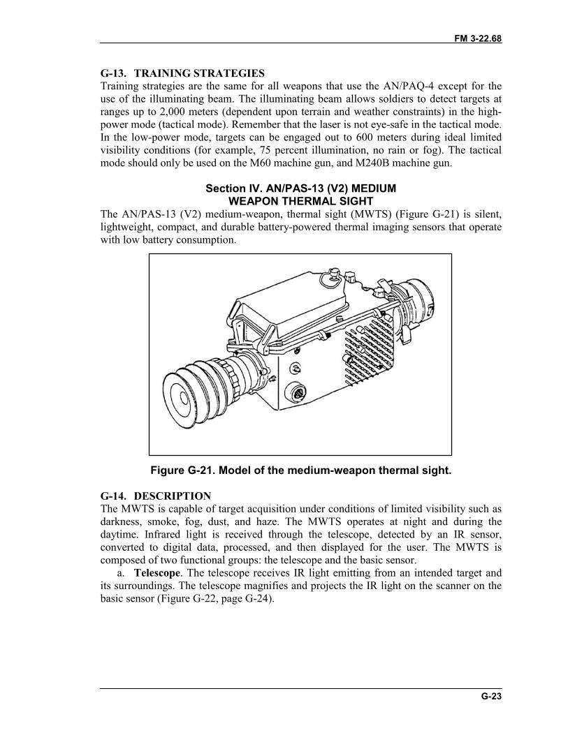
FM 3-22.68
G-23
G-13. TRAINING STRATEGIESTraining strategies are the same for all weapons that use the AN/PAQ-4 except for theuse of the illuminating beam. The illuminating beam allows soldiers to detect targets atranges up to 2,000 meters (dependent upon terrain and weather constraints) in the high-power mode (tactical mode). Remember that the laser is not eye-safe in the tactical mode.In the low-power mode, targets can be engaged out to 600 meters during ideal limitedvisibility conditions (for example, 75 percent illumination, no rain or fog). The tacticalmode should only be used on the M60 machine gun, and M240B machine gun.
Section IV. AN/PAS-13 (V2) MEDIUMWEAPON THERMAL SIGHT
The AN/PAS-13 (V2) medium-weapon, thermal sight (MWTS) (Figure G-21) is silent,lightweight, compact, and durable battery-powered thermal imaging sensors that operatewith low battery consumption.
Figure G-21. Model of the medium-weapon thermal sight.
G-14. DESCRIPTIONThe MWTS is capable of target acquisition under conditions of limited visibility such asdarkness, smoke, fog, dust, and haze. The MWTS operates at night and during thedaytime. Infrared light is received through the telescope, detected by an IR sensor,converted to digital data, processed, and then displayed for the user. The MWTS iscomposed of two functional groups: the telescope and the basic sensor.
a. Telescope. The telescope receives IR light emitting from an intended target andits surroundings. The telescope magnifies and projects the IR light on the scanner on thebasic sensor (Figure G-22, page G-24).
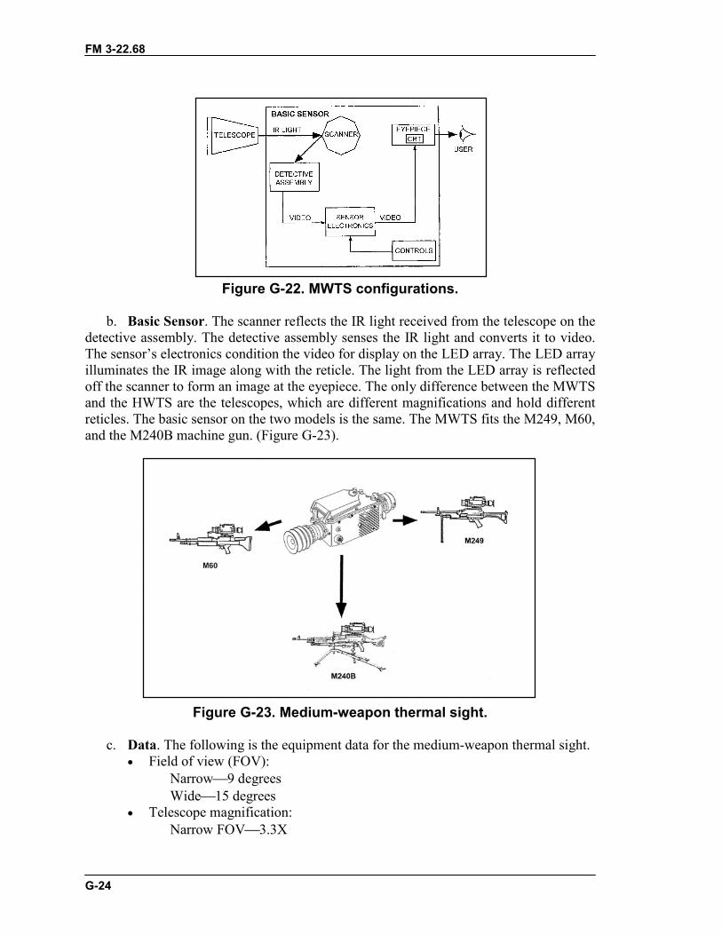
FM 3-22.68
G-24
Figure G-22. MWTS configurations.
b. Basic Sensor. The scanner reflects the IR light received from the telescope on thedetective assembly. The detective assembly senses the IR light and converts it to video.The sensor’s electronics condition the video for display on the LED array. The LED arrayilluminates the IR image along with the reticle. The light from the LED array is reflectedoff the scanner to form an image at the eyepiece. The only difference between the MWTSand the HWTS are the telescopes, which are different magnifications and hold differentreticles. The basic sensor on the two models is the same. The MWTS fits the M249, M60,and the M240B machine gun. (Figure G-23).
Figure G-23. Medium-weapon thermal sight.
c. Data. The following is the equipment data for the medium-weapon thermal sight.� Field of view (FOV):
Narrow�9 degreesWide�15 degrees
� Telescope magnification:Narrow FOV�3.3X
FM 3-22.68
G-25
Wide FOV�2X� Length�15.5 inches� Width�6.25 inches� Height�6.25 inches� Weight�4.1 pounds� Power consumption:
ON mode�12.0 wattsSTANDBY mode�5.5 watts
� Battery life:71 percent STANDBY mode�10 hoursEMERGENCY mode�3.5 hours
G-15. OPERATIONThe MWTS has three modes of operation: STANDBY, ON, and EMERGENCY.Figure G-24, page G-26, shows controls and indicators.
a. Modes.(1) STANDBY Mode. When the system is first turned on, the MWTS begins a cool-
down period of about 2 minutes. After the cool-down period, the MWTS enters theSTANDBY mode. During the STANDBY mode, power is not applied to the scanner ordisplay to extend the life of the battery.
(2) ON Mode. When the MWTS is in the STANDBY mode and pressure is applied tothe eyecup, the MWTS switches to the ON mode, and a switch engages to provide powerto the scanner and display. After a three-second delay, the system is fully operational.
(c) EMERGENCY mode. When switched to the EMERGENCY mode, the MWTScontinuously applies power to the entire system. This mode allows the operator to bypassthe 3-second delay experienced when switching from the STANDBY to the ON mode.Since power is applied to the entire system while in the emergency mode, battery life isgreatly reduced.
b. Controls and Switches.(1) The CONTRAST CONTROL (1) adjusts the contrast of the thermal scene. When
turned fully clockwise to AUTO, contrast is automatically set.(2) The EMERGENCY CONTROL (2) overrides the eyecup switch and turns entire
system on, which places the MWTS in the EMERGENCY mode.(3) The BRIGHTNESS CONTROL (3) is a nine-position rotary switch with an off
detent position (turned fully counterclockwise). The purpose is to turn the system on oroff and adjust the brightness of the eyepiece display.
(4) The FOCUS RING (4) adjusts the telescope focus from 20 meters to infinity. Itrequires a manual adjustment and affects both the wide and narrow fields of view.
(5) The FIELD OF VIEW RING (5) is located on the telescope. It has a wide and anarrow field of view. The wide FOV is for using low magnification during targetdetection, and the narrow FOV is for using high magnification during recognition andengagement.
(6) The RETICLE SELECT SWITCH (6) selects one of the available reticlesdepending on the MWTS model (medium or heavy). It must be held for 2 seconds toenable reticle changes. After 2 seconds, release the switch to cycle to the next reticle.This control is disabled after 10 seconds of inactivity.
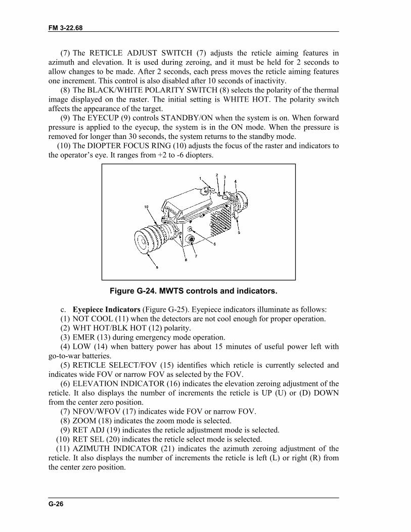
FM 3-22.68
G-26
(7) The RETICLE ADJUST SWITCH (7) adjusts the reticle aiming features inazimuth and elevation. It is used during zeroing, and it must be held for 2 seconds toallow changes to be made. After 2 seconds, each press moves the reticle aiming featuresone increment. This control is also disabled after 10 seconds of inactivity.
(8) The BLACK/WHITE POLARITY SWITCH (8) selects the polarity of the thermalimage displayed on the raster. The initial setting is WHITE HOT. The polarity switchaffects the appearance of the target.
(9) The EYECUP (9) controls STANDBY/ON when the system is on. When forwardpressure is applied to the eyecup, the system is in the ON mode. When the pressure isremoved for longer than 30 seconds, the system returns to the standby mode.
(10) The DIOPTER FOCUS RING (10) adjusts the focus of the raster and indicators tothe operator’s eye. It ranges from +2 to -6 diopters.
Figure G-24. MWTS controls and indicators.
c. Eyepiece Indicators (Figure G-25). Eyepiece indicators illuminate as follows:(1) NOT COOL (11) when the detectors are not cool enough for proper operation.(2) WHT HOT/BLK HOT (12) polarity.(3) EMER (13) during emergency mode operation.(4) LOW (14) when battery power has about 15 minutes of useful power left with
go-to-war batteries.(5) RETICLE SELECT/FOV (15) identifies which reticle is currently selected and
indicates wide FOV or narrow FOV as selected by the FOV.(6) ELEVATION INDICATOR (16) indicates the elevation zeroing adjustment of the
reticle. It also displays the number of increments the reticle is UP (U) or (D) DOWNfrom the center zero position.
(7) NFOV/WFOV (17) indicates wide FOV or narrow FOV.(8) ZOOM (18) indicates the zoom mode is selected.(9) RET ADJ (19) indicates the reticle adjustment mode is selected.
(10) RET SEL (20) indicates the reticle select mode is selected.(11) AZIMUTH INDICATOR (21) indicates the azimuth zeroing adjustment of the
reticle. It also displays the number of increments the reticle is left (L) or right (R) fromthe center zero position.
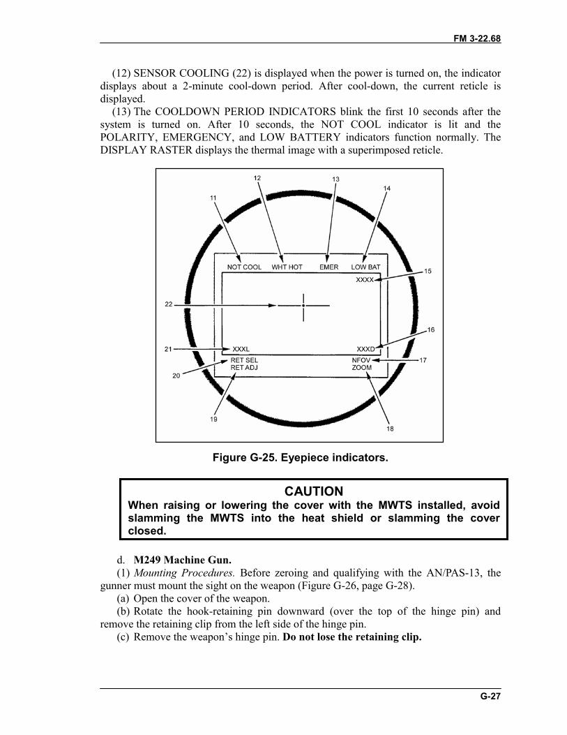
FM 3-22.68
G-27
(12) SENSOR COOLING (22) is displayed when the power is turned on, the indicatordisplays about a 2-minute cool-down period. After cool-down, the current reticle isdisplayed.
(13) The COOLDOWN PERIOD INDICATORS blink the first 10 seconds after thesystem is turned on. After 10 seconds, the NOT COOL indicator is lit and thePOLARITY, EMERGENCY, and LOW BATTERY indicators function normally. TheDISPLAY RASTER displays the thermal image with a superimposed reticle.
Figure G-25. Eyepiece indicators.
d. M249 Machine Gun. (1) Mounting Procedures. Before zeroing and qualifying with the AN/PAS-13, thegunner must mount the sight on the weapon (Figure G-26, page G-28).
(a) Open the cover of the weapon.(b) Rotate the hook-retaining pin downward (over the top of the hinge pin) and
remove the retaining clip from the left side of the hinge pin.(c) Remove the weapon’s hinge pin. Do not lose the retaining clip.
CAUTIONWhen raising or lowering the cover with the MWTS installed, avoidslamming the MWTS into the heat shield or slamming the coverclosed.
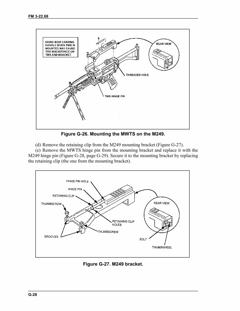
FM 3-22.68
G-28
Figure G-26. Mounting the MWTS on the M249.
(d) Remove the retaining clip from the M249 mounting bracket (Figure G-27).(e) Remove the MWTS hinge pin from the mounting bracket and replace it with the
M249 hinge pin (Figure G-28, page G-29). Secure it to the mounting bracket by replacingthe retaining clip (the one from the mounting bracket).
Figure G-27. M249 bracket.
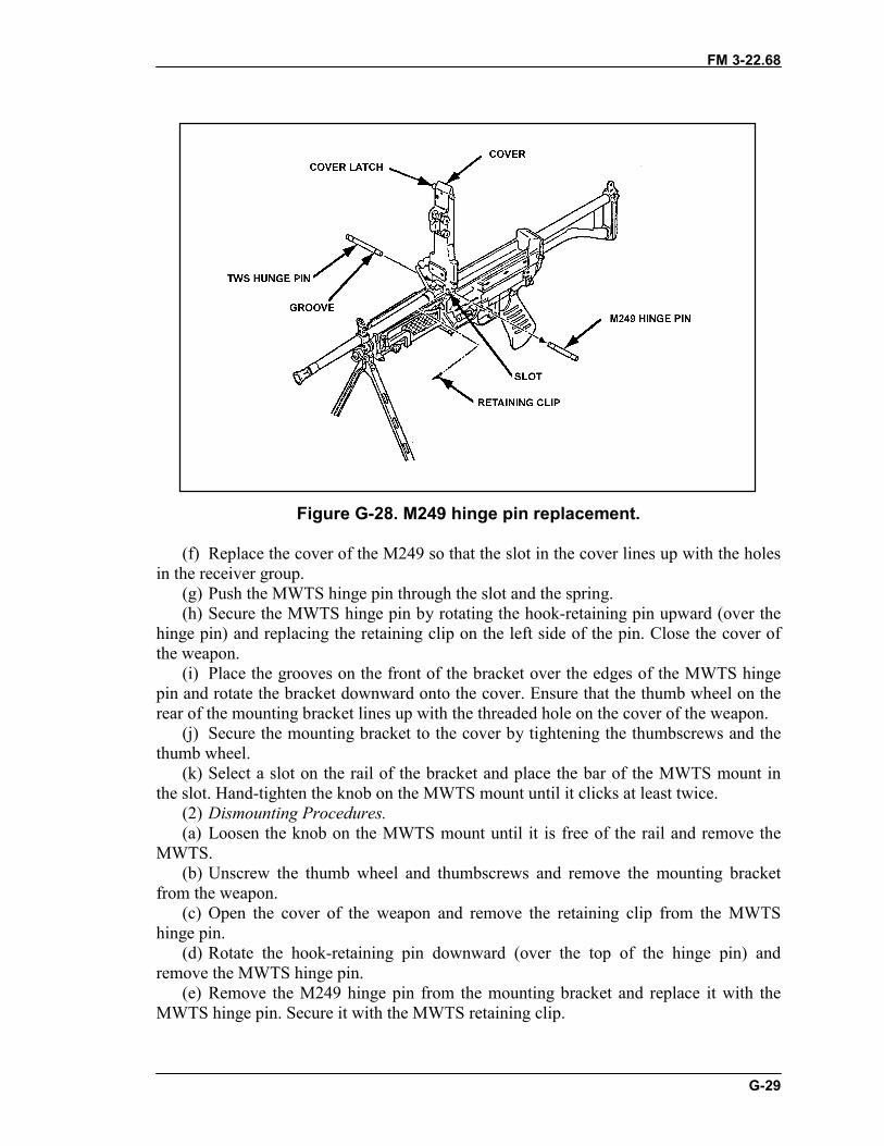
FM 3-22.68
G-29
Figure G-28. M249 hinge pin replacement.
(f) Replace the cover of the M249 so that the slot in the cover lines up with the holesin the receiver group.
(g) Push the MWTS hinge pin through the slot and the spring.(h) Secure the MWTS hinge pin by rotating the hook-retaining pin upward (over the
hinge pin) and replacing the retaining clip on the left side of the pin. Close the cover ofthe weapon.
(i) Place the grooves on the front of the bracket over the edges of the MWTS hingepin and rotate the bracket downward onto the cover. Ensure that the thumb wheel on therear of the mounting bracket lines up with the threaded hole on the cover of the weapon.
(j) Secure the mounting bracket to the cover by tightening the thumbscrews and thethumb wheel.
(k) Select a slot on the rail of the bracket and place the bar of the MWTS mount inthe slot. Hand-tighten the knob on the MWTS mount until it clicks at least twice.
(2) Dismounting Procedures.(a) Loosen the knob on the MWTS mount until it is free of the rail and remove the
MWTS.(b) Unscrew the thumb wheel and thumbscrews and remove the mounting bracket
from the weapon.(c) Open the cover of the weapon and remove the retaining clip from the MWTS
hinge pin.(d) Rotate the hook-retaining pin downward (over the top of the hinge pin) and
remove the MWTS hinge pin.(e) Remove the M249 hinge pin from the mounting bracket and replace it with the
MWTS hinge pin. Secure it with the MWTS retaining clip.
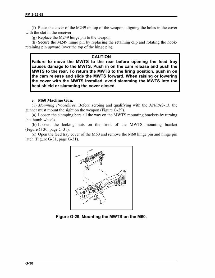
FM 3-22.68
G-30
(f) Place the cover of the M249 on top of the weapon, aligning the holes in the coverwith the slot in the receiver.
(g) Replace the M249 hinge pin to the weapon.(h) Secure the M249 hinge pin by replacing the retaining clip and rotating the hook-
retaining pin upward (over the top of the hinge pin).
CAUTIONFailure to move the MWTS to the rear before opening the feed traycauses damage to the MWTS. Push in on the cam release and push theMWTS to the rear. To return the MWTS to the firing position, push in onthe cam release and slide the MWTS forward. When raising or loweringthe cover with the MWTS installed, avoid slamming the MWTS into theheat shield or slamming the cover closed.
e. M60 Machine Gun. (1) Mounting Procedures. Before zeroing and qualifying with the AN/PAS-13, thegunner must mount the sight on the weapon (Figure G-29).
(a) Loosen the clamping bars all the way on the MWTS mounting brackets by turningthe thumb wheels.
(b) Loosen the locking nuts on the front of the MWTS mounting bracket(Figure G-30, page G-31).
(c) Open the feed tray cover of the M60 and remove the M60 hinge pin and hinge pinlatch (Figure G-31, page G-31).
Figure G-29. Mounting the MWTS on the M60.
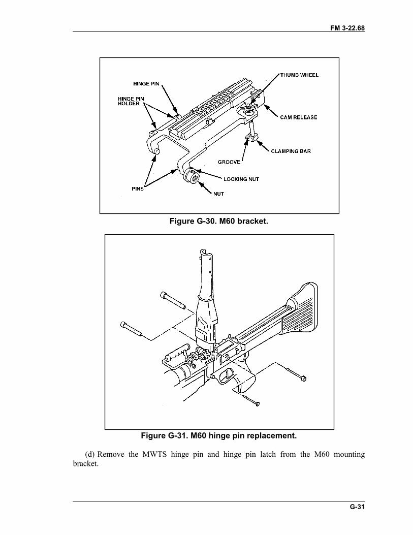
FM 3-22.68
G-31
Figure G-30. M60 bracket.
Figure G-31. M60 hinge pin replacement.
(d) Remove the MWTS hinge pin and hinge pin latch from the M60 mountingbracket.
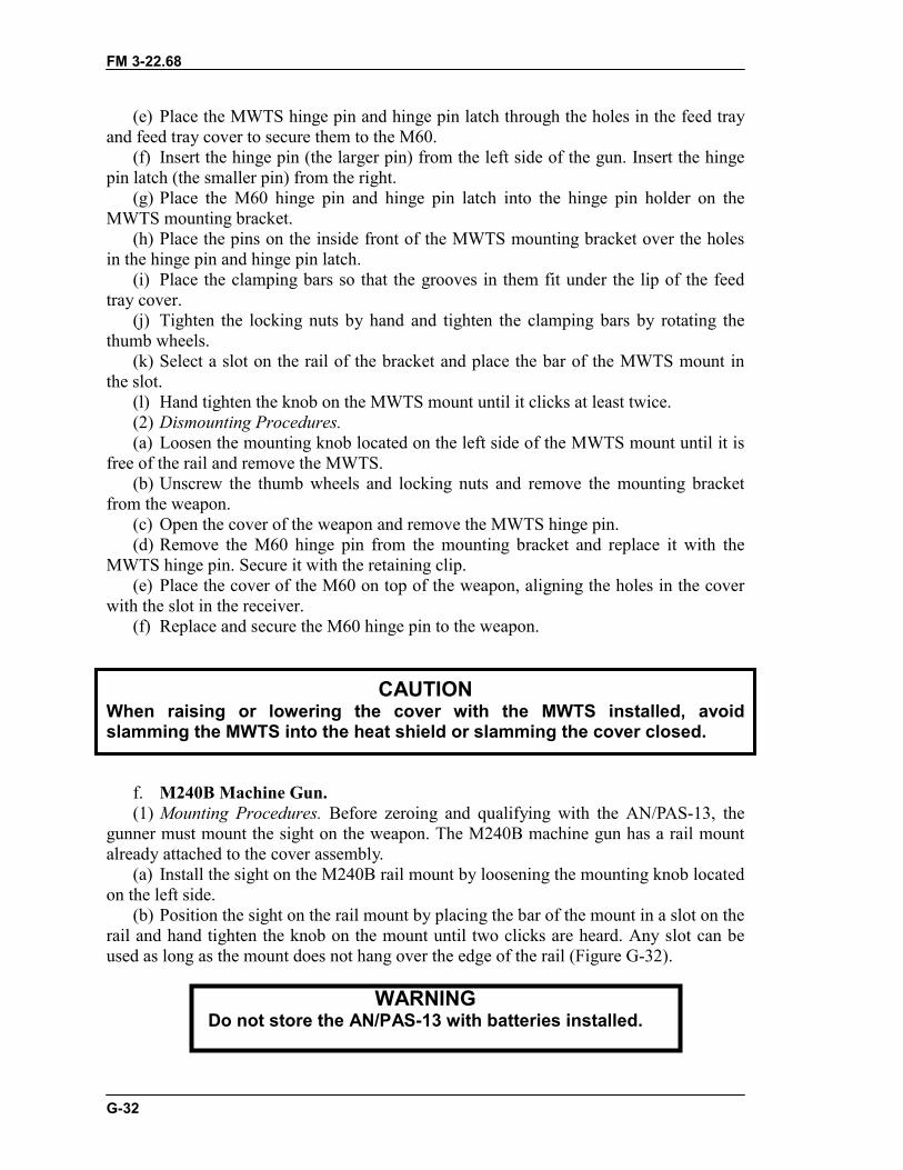
FM 3-22.68
G-32
(e) Place the MWTS hinge pin and hinge pin latch through the holes in the feed trayand feed tray cover to secure them to the M60.
(f) Insert the hinge pin (the larger pin) from the left side of the gun. Insert the hingepin latch (the smaller pin) from the right.
(g) Place the M60 hinge pin and hinge pin latch into the hinge pin holder on theMWTS mounting bracket.
(h) Place the pins on the inside front of the MWTS mounting bracket over the holesin the hinge pin and hinge pin latch.
(i) Place the clamping bars so that the grooves in them fit under the lip of the feedtray cover.
(j) Tighten the locking nuts by hand and tighten the clamping bars by rotating thethumb wheels.
(k) Select a slot on the rail of the bracket and place the bar of the MWTS mount inthe slot.
(l) Hand tighten the knob on the MWTS mount until it clicks at least twice.(2) Dismounting Procedures.(a) Loosen the mounting knob located on the left side of the MWTS mount until it is
free of the rail and remove the MWTS.(b) Unscrew the thumb wheels and locking nuts and remove the mounting bracket
from the weapon.(c) Open the cover of the weapon and remove the MWTS hinge pin.(d) Remove the M60 hinge pin from the mounting bracket and replace it with the
MWTS hinge pin. Secure it with the retaining clip.(e) Place the cover of the M60 on top of the weapon, aligning the holes in the cover
with the slot in the receiver.(f) Replace and secure the M60 hinge pin to the weapon.
CAUTIONWhen raising or lowering the cover with the MWTS installed, avoidslamming the MWTS into the heat shield or slamming the cover closed.
f. M240B Machine Gun.(1) Mounting Procedures. Before zeroing and qualifying with the AN/PAS-13, the
gunner must mount the sight on the weapon. The M240B machine gun has a rail mountalready attached to the cover assembly.
(a) Install the sight on the M240B rail mount by loosening the mounting knob locatedon the left side.
(b) Position the sight on the rail mount by placing the bar of the mount in a slot on therail and hand tighten the knob on the mount until two clicks are heard. Any slot can beused as long as the mount does not hang over the edge of the rail (Figure G-32).
WARNINGDo not store the AN/PAS-13 with batteries installed.
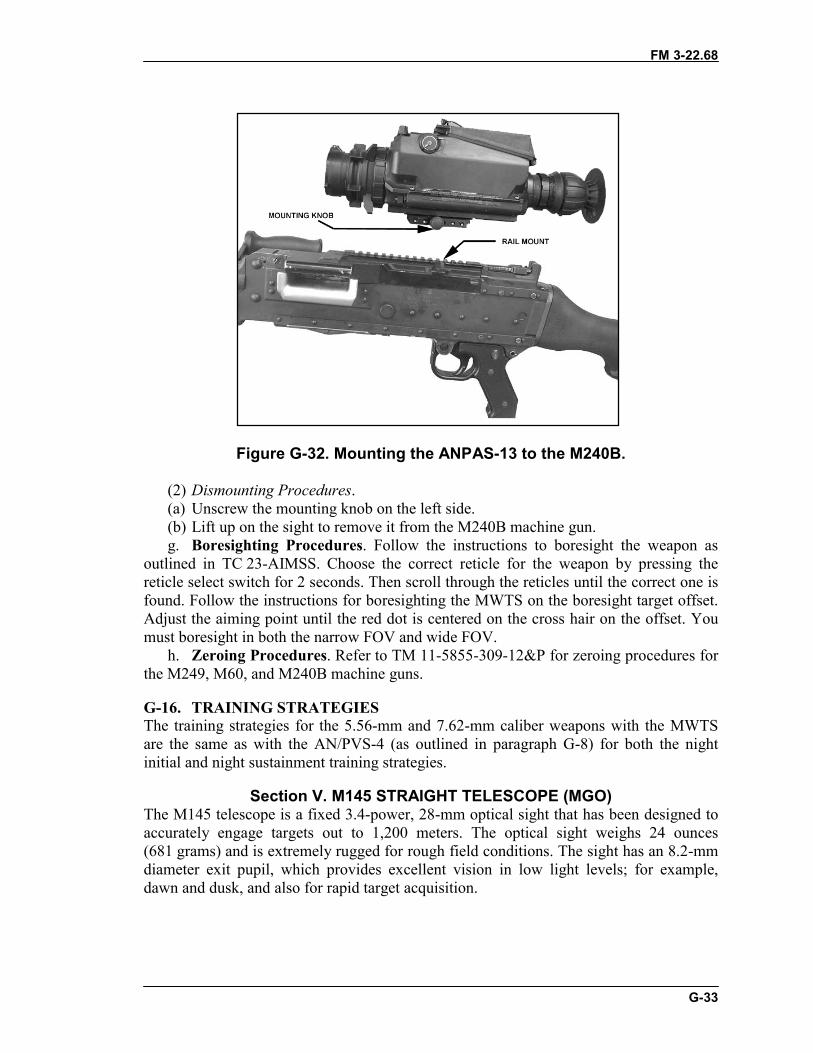
FM 3-22.68
G-33
Figure G-32. Mounting the ANPAS-13 to the M240B.
(2) Dismounting Procedures.(a) Unscrew the mounting knob on the left side.(b) Lift up on the sight to remove it from the M240B machine gun.g. Boresighting Procedures. Follow the instructions to boresight the weapon as
outlined in TC 23-AIMSS. Choose the correct reticle for the weapon by pressing thereticle select switch for 2 seconds. Then scroll through the reticles until the correct one isfound. Follow the instructions for boresighting the MWTS on the boresight target offset.Adjust the aiming point until the red dot is centered on the cross hair on the offset. Youmust boresight in both the narrow FOV and wide FOV.
h. Zeroing Procedures. Refer to TM 11-5855-309-12&P for zeroing procedures forthe M249, M60, and M240B machine guns.
G-16. TRAINING STRATEGIESThe training strategies for the 5.56-mm and 7.62-mm caliber weapons with the MWTSare the same as with the AN/PVS-4 (as outlined in paragraph G-8) for both the nightinitial and night sustainment training strategies.
Section V. M145 STRAIGHT TELESCOPE (MGO)The M145 telescope is a fixed 3.4-power, 28-mm optical sight that has been designed toaccurately engage targets out to 1,200 meters. The optical sight weighs 24 ounces(681 grams) and is extremely rugged for rough field conditions. The sight has an 8.2-mmdiameter exit pupil, which provides excellent vision in low light levels; for example,dawn and dusk, and also for rapid target acquisition.
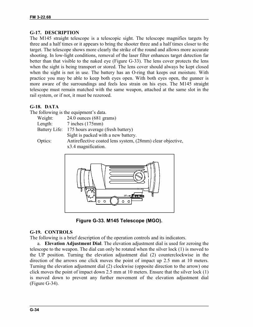
FM 3-22.68
G-34
G-17. DESCRIPTIONThe M145 straight telescope is a telescopic sight. The telescope magnifies targets bythree and a half times or it appears to bring the shooter three and a half times closer to thetarget. The telescope shows more clearly the strike of the round and allows more accurateshooting. In low-light conditions, removal of the laser filter enhances target detection farbetter than that visible to the naked eye (Figure G-33). The lens cover protects the lenswhen the sight is being transport or stored. The lens cover should always be kept closedwhen the sight is not in use. The battery has an O-ring that keeps out moisture. Withpractice you may be able to keep both eyes open. With both eyes open, the gunner ismore aware of the surroundings and feels less strain on his eyes. The M145 straighttelescope must remain matched with the same weapon, attached at the same slot in therail system, or if not, it must be rezeroed.
G-18. DATAThe following is the equipment’s data.
Weight: 24.0 ounces (681 grams)Length: 7 inches (175mm)Battery Life: 175 hours average (fresh battery)
Sight is packed with a new battery.Optics: Antireflective coated lens system, (28mm) clear objective,
x3.4 magnification.
Figure G-33. M145 Telescope (MGO).
G-19. CONTROLSThe following is a brief description of the operation controls and its indicators.
a. Elevation Adjustment Dial. The elevation adjustment dial is used for zeroing thetelescope to the weapon. The dial can only be rotated when the silver lock (1) is moved tothe UP position. Turning the elevation adjustment dial (2) counterclockwise in thedirection of the arrows one click moves the point of impact up 2.5 mm at 10 meters.Turning the elevation adjustment dial (2) clockwise (opposite direction to the arrow) oneclick moves the point of impact down 2.5 mm at 10 meters. Ensure that the silver lock (1)is moved down to prevent any further movement of the elevation adjustment dial(Figure G-34).
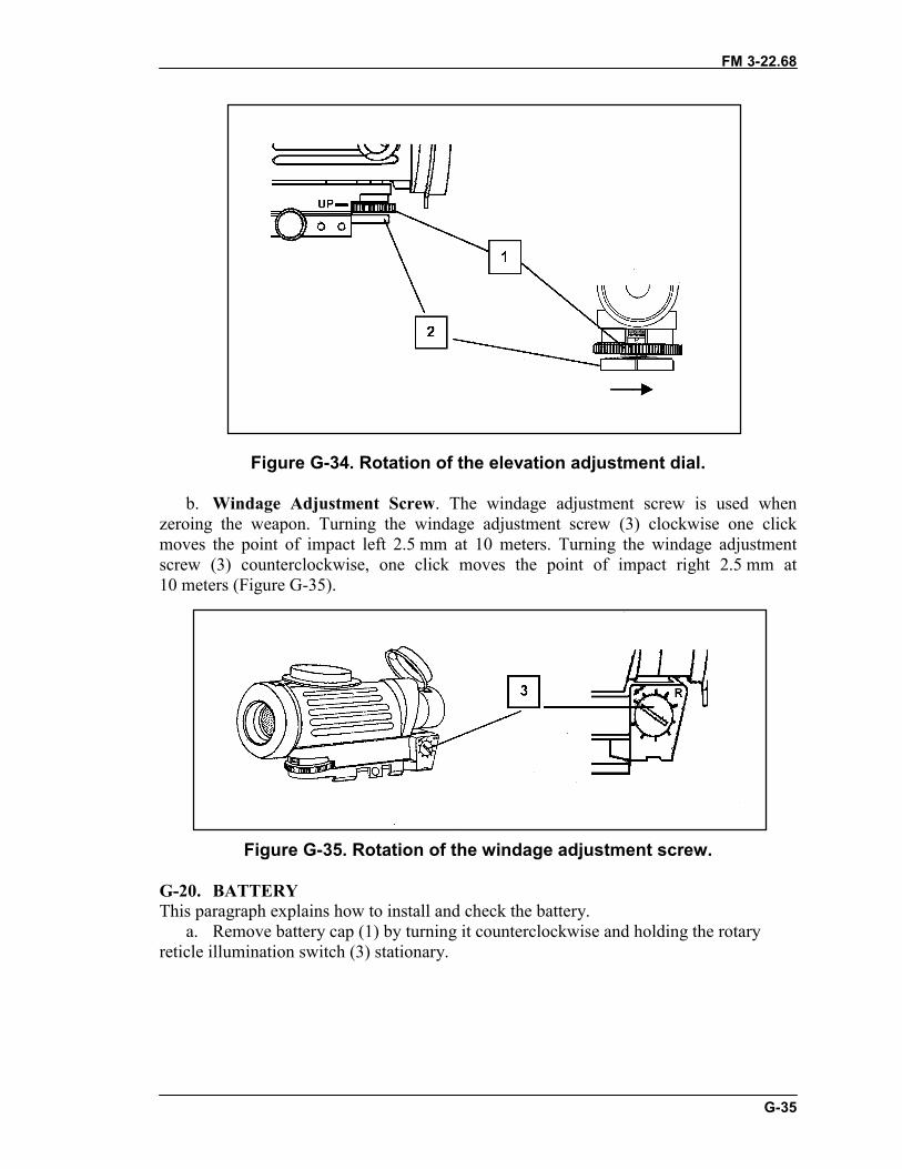
FM 3-22.68
G-35
Figure G-34. Rotation of the elevation adjustment dial.
b. Windage Adjustment Screw. The windage adjustment screw is used whenzeroing the weapon. Turning the windage adjustment screw (3) clockwise one clickmoves the point of impact left 2.5 mm at 10 meters. Turning the windage adjustmentscrew (3) counterclockwise, one click moves the point of impact right 2.5 mm at10 meters (Figure G-35).
Figure G-35. Rotation of the windage adjustment screw.
G-20. BATTERYThis paragraph explains how to install and check the battery.
a. Remove battery cap (1) by turning it counterclockwise and holding the rotaryreticle illumination switch (3) stationary.
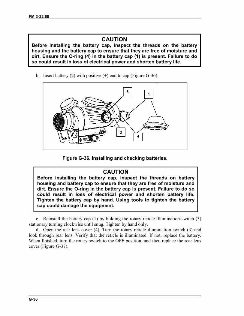
FM 3-22.68
G-36
b. Insert battery (2) with positive (+) end to cap (Figure G-36).
Figure G-36. Installing and checking batteries.
c. Reinstall the battery cap (1) by holding the rotary reticle illumination switch (3)stationary turning clockwise until snug. Tighten by hand only.
d. Open the rear lens cover (4). Turn the rotary reticle illumination switch (3) andlook through rear lens. Verify that the reticle is illuminated. If not, replace the battery.When finished, turn the rotary switch to the OFF position, and then replace the rear lenscover (Figure G-37).
CAUTIONBefore installing the battery cap, inspect the threads on the batteryhousing and the battery cap to ensure that they are free of moisture anddirt. Ensure the O-ring (4) in the battery cap (1) is present. Failure to doso could result in loss of electrical power and shorten battery life.
CAUTIONBefore installing the battery cap, inspect the threads on batteryhousing and battery cap to ensure that they are free of moisture anddirt. Ensure the O-ring in the battery cap is present. Failure to do socould result in loss of electrical power and shorten battery life.Tighten the battery cap by hand. Using tools to tighten the batterycap could damage the equipment.
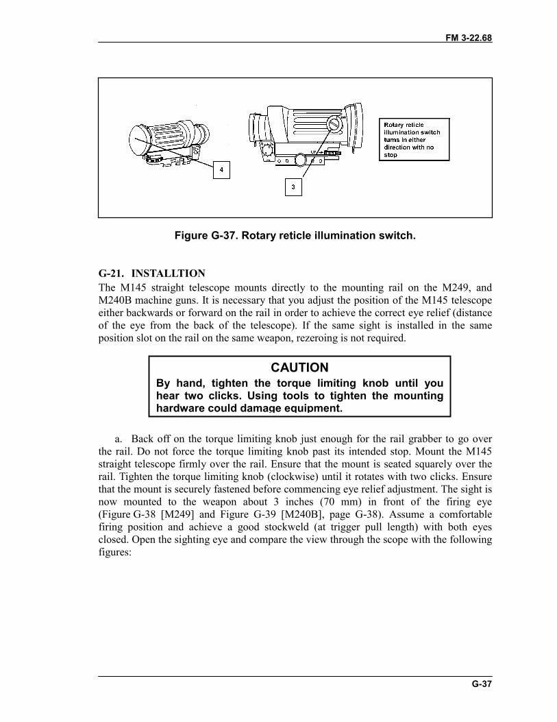
FM 3-22.68
G-37
Figure G-37. Rotary reticle illumination switch.
G-21. INSTALLTIONThe M145 straight telescope mounts directly to the mounting rail on the M249, andM240B machine guns. It is necessary that you adjust the position of the M145 telescopeeither backwards or forward on the rail in order to achieve the correct eye relief (distanceof the eye from the back of the telescope). If the same sight is installed in the sameposition slot on the rail on the same weapon, rezeroing is not required.
a. Back off on the torque limiting knob just enough for the rail grabber to go overthe rail. Do not force the torque limiting knob past its intended stop. Mount the M145straight telescope firmly over the rail. Ensure that the mount is seated squarely over therail. Tighten the torque limiting knob (clockwise) until it rotates with two clicks. Ensurethat the mount is securely fastened before commencing eye relief adjustment. The sight isnow mounted to the weapon about 3 inches (70 mm) in front of the firing eye(Figure G-38 [M249] and Figure G-39 [M240B], page G-38). Assume a comfortablefiring position and achieve a good stockweld (at trigger pull length) with both eyesclosed. Open the sighting eye and compare the view through the scope with the followingfigures:
CAUTIONBy hand, tighten the torque limiting knob until youhear two clicks. Using tools to tighten the mountinghardware could damage equipment.
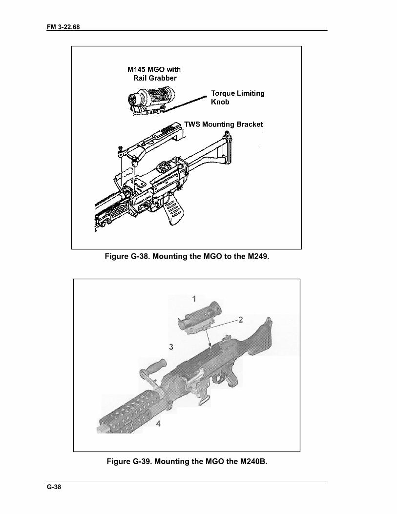
FM 3-22.68
G-38
Figure G-38. Mounting the MGO to the M249.
Figure G-39. Mounting the MGO the M240B.
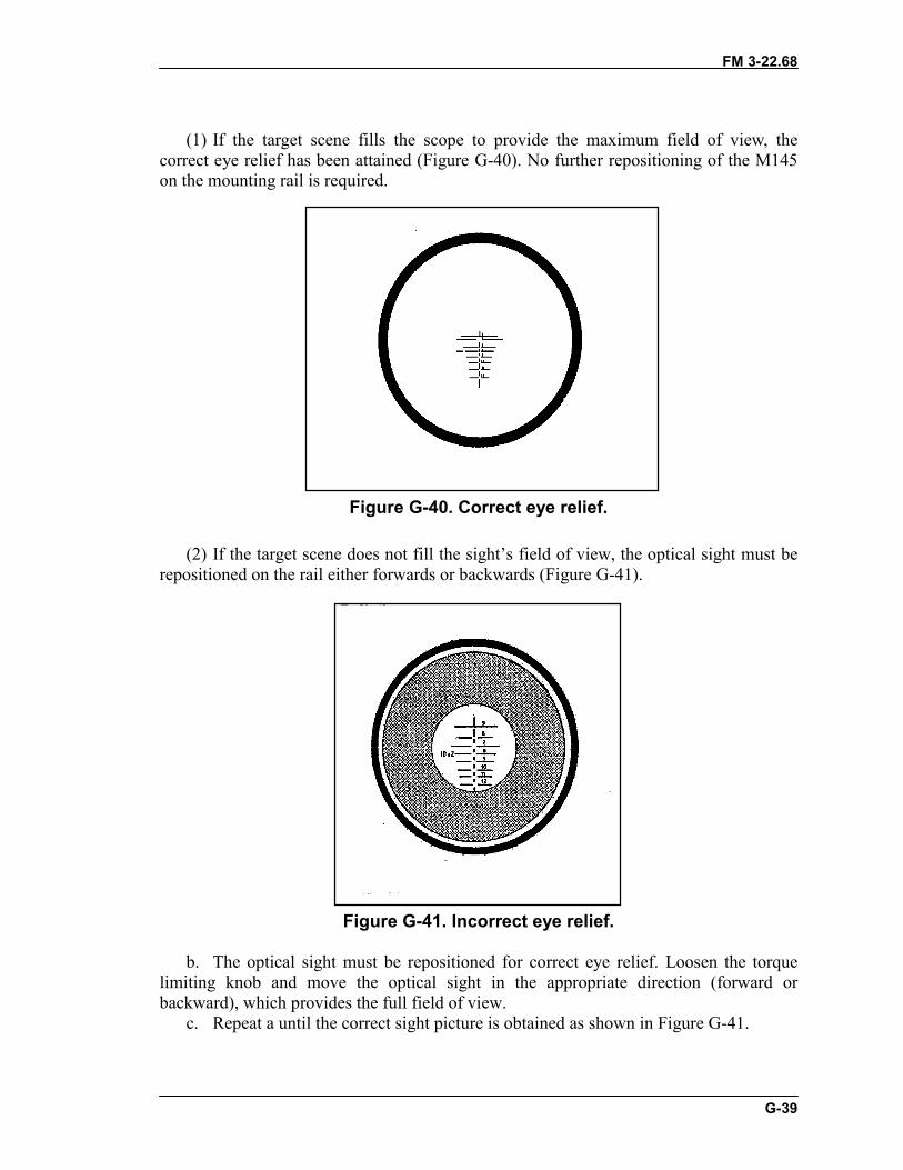
FM 3-22.68
G-39
(1) If the target scene fills the scope to provide the maximum field of view, thecorrect eye relief has been attained (Figure G-40). No further repositioning of the M145on the mounting rail is required.
Figure G-40. Correct eye relief.
(2) If the target scene does not fill the sight’s field of view, the optical sight must berepositioned on the rail either forwards or backwards (Figure G-41).
Figure G-41. Incorrect eye relief.
b. The optical sight must be repositioned for correct eye relief. Loosen the torquelimiting knob and move the optical sight in the appropriate direction (forward orbackward), which provides the full field of view.
c. Repeat a until the correct sight picture is obtained as shown in Figure G-41.
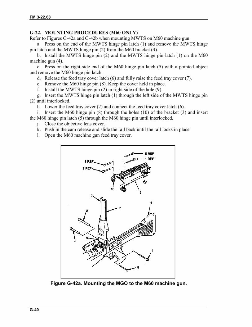
FM 3-22.68
G-40
G-22. MOUNTING PROCEDURES (M60 ONLY)Refer to Figures G-42a and G-42b when mounting MWTS on M60 machine gun.
a. Press on the end of the MWTS hinge pin latch (1) and remove the MWTS hingepin latch and the MWTS hinge pin (2) from the M60 bracket (3).
b. Install the MWTS hinge pin (2) and the MWTS hinge pin latch (1) on the M60machine gun (4).
c. Press on the right side end of the M60 hinge pin latch (5) with a pointed objectand remove the M60 hinge pin latch.
d. Release the feed tray cover latch (6) and fully raise the feed tray cover (7).e. Remove the M60 hinge pin (8). Keep the cover held in place.f. Install the MWTS hinge pin (2) in right side of the hole (9).g. Insert the MWTS hinge pin latch (1) through the left side of the MWTS hinge pin
(2) until interlocked.h. Lower the feed tray cover (7) and connect the feed tray cover latch (6).i. Insert the M60 hinge pin (8) through the holes (10) of the bracket (3) and insert
the M60 hinge pin latch (5) through the M60 hinge pin until interlocked.j. Close the objective lens cover.k. Push in the cam release and slide the rail back until the rail locks in place.l. Open the M60 machine gun feed tray cover.
Figure G-42a. Mounting the MGO to the M60 machine gun.
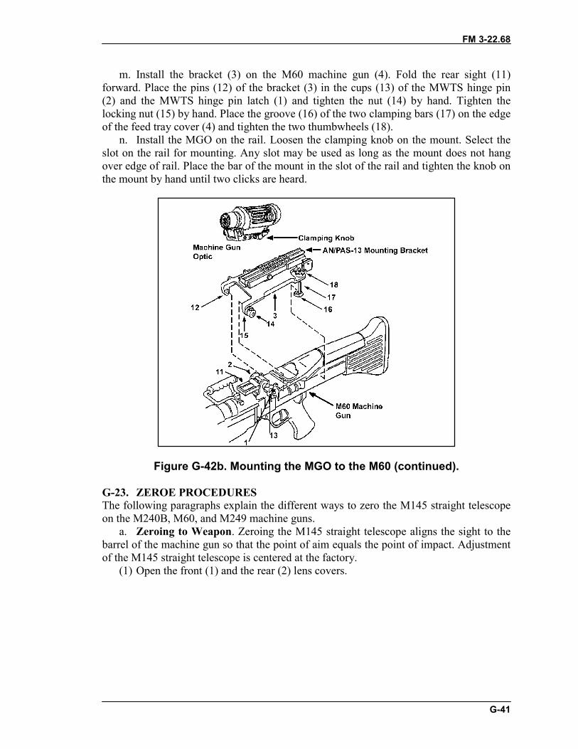
FM 3-22.68
G-41
m. Install the bracket (3) on the M60 machine gun (4). Fold the rear sight (11)forward. Place the pins (12) of the bracket (3) in the cups (13) of the MWTS hinge pin(2) and the MWTS hinge pin latch (1) and tighten the nut (14) by hand. Tighten thelocking nut (15) by hand. Place the groove (16) of the two clamping bars (17) on the edgeof the feed tray cover (4) and tighten the two thumbwheels (18).
n. Install the MGO on the rail. Loosen the clamping knob on the mount. Select theslot on the rail for mounting. Any slot may be used as long as the mount does not hangover edge of rail. Place the bar of the mount in the slot of the rail and tighten the knob onthe mount by hand until two clicks are heard.
Figure G-42b. Mounting the MGO to the M60 (continued).
G-23. ZEROE PROCEDURESThe following paragraphs explain the different ways to zero the M145 straight telescopeon the M240B, M60, and M249 machine guns.
a. Zeroing to Weapon. Zeroing the M145 straight telescope aligns the sight to thebarrel of the machine gun so that the point of aim equals the point of impact. Adjustmentof the M145 straight telescope is centered at the factory.
(1) Open the front (1) and the rear (2) lens covers.
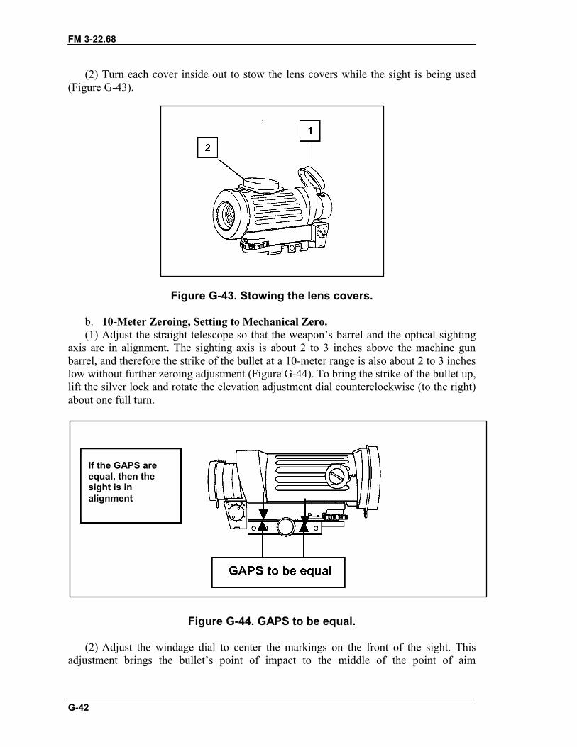
FM 3-22.68
G-42
(2) Turn each cover inside out to stow the lens covers while the sight is being used(Figure G-43).
Figure G-43. Stowing the lens covers.
b. 10-Meter Zeroing, Setting to Mechanical Zero.(1) Adjust the straight telescope so that the weapon’s barrel and the optical sighting
axis are in alignment. The sighting axis is about 2 to 3 inches above the machine gunbarrel, and therefore the strike of the bullet at a 10-meter range is also about 2 to 3 incheslow without further zeroing adjustment (Figure G-44). To bring the strike of the bullet up,lift the silver lock and rotate the elevation adjustment dial counterclockwise (to the right)about one full turn.
Figure G-44. GAPS to be equal.
(2) Adjust the windage dial to center the markings on the front of the sight. Thisadjustment brings the bullet’s point of impact to the middle of the point of aim
If the GAPS areequal, then thesight is inalignment
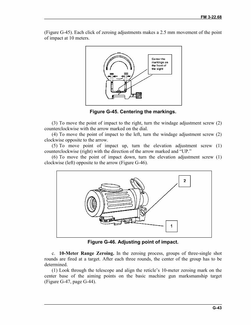
FM 3-22.68
G-43
(Figure G-45). Each click of zeroing adjustments makes a 2.5 mm movement of the pointof impact at 10 meters.
Figure G-45. Centering the markings.
(3) To move the point of impact to the right, turn the windage adjustment screw (2)counterclockwise with the arrow marked on the dial.
(4) To move the point of impact to the left, turn the windage adjustment screw (2)clockwise opposite to the arrow.
(5) To move point of impact up, turn the elevation adjustment screw (1)counterclockwise (right) with the direction of the arrow marked and “UP.”
(6) To move the point of impact down, turn the elevation adjustment screw (1)clockwise (left) opposite to the arrow (Figure G-46).
Figure G-46. Adjusting point of impact.
c. 10-Meter Range Zeroing. In the zeroing process, groups of three-single shotrounds are fired at a target. After each three rounds, the center of the group has to bedetermined.
(1) Look through the telescope and align the reticle’s 10-meter zeroing mark on thecenter base of the aiming points on the basic machine gun marksmanship target(Figure G-47, page G-44).
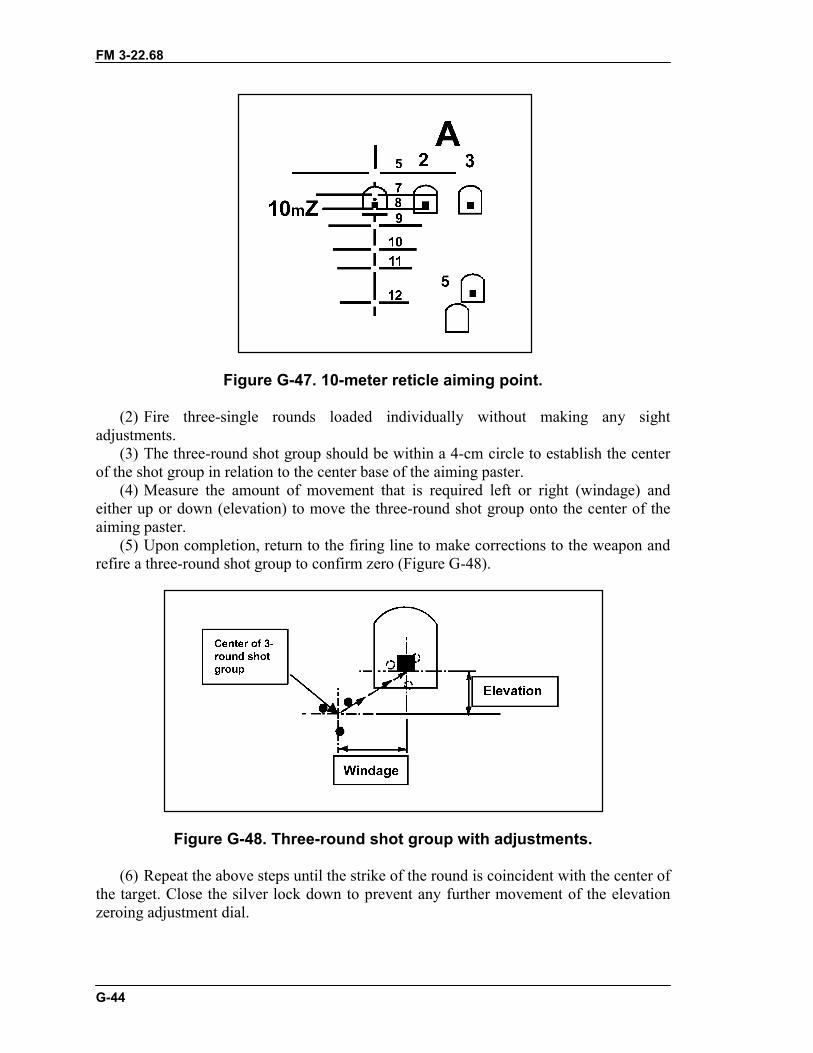
FM 3-22.68
G-44
Figure G-47. 10-meter reticle aiming point.
(2) Fire three-single rounds loaded individually without making any sightadjustments.
(3) The three-round shot group should be within a 4-cm circle to establish the centerof the shot group in relation to the center base of the aiming paster.
(4) Measure the amount of movement that is required left or right (windage) andeither up or down (elevation) to move the three-round shot group onto the center of theaiming paster.
(5) Upon completion, return to the firing line to make corrections to the weapon andrefire a three-round shot group to confirm zero (Figure G-48).
Figure G-48. Three-round shot group with adjustments.
(6) Repeat the above steps until the strike of the round is coincident with the center ofthe target. Close the silver lock down to prevent any further movement of the elevationzeroing adjustment dial.
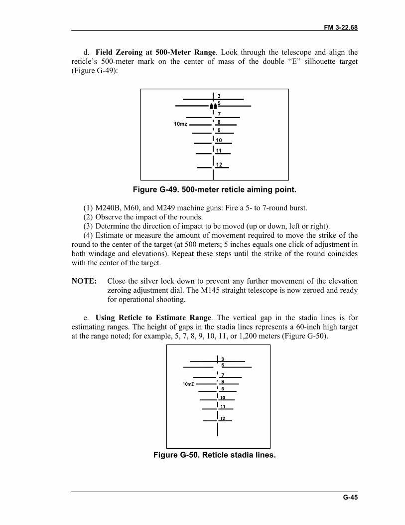
FM 3-22.68
G-45
d. Field Zeroing at 500-Meter Range. Look through the telescope and align thereticle’s 500-meter mark on the center of mass of the double “E” silhouette target(Figure G-49):
Figure G-49. 500-meter reticle aiming point.
(1) M240B, M60, and M249 machine guns: Fire a 5- to 7-round burst.(2) Observe the impact of the rounds.(3) Determine the direction of impact to be moved (up or down, left or right).(4) Estimate or measure the amount of movement required to move the strike of the
round to the center of the target (at 500 meters; 5 inches equals one click of adjustment inboth windage and elevations). Repeat these steps until the strike of the round coincideswith the center of the target.
NOTE: Close the silver lock down to prevent any further movement of the elevationzeroing adjustment dial. The M145 straight telescope is now zeroed and readyfor operational shooting.
e. Using Reticle to Estimate Range. The vertical gap in the stadia lines is forestimating ranges. The height of gaps in the stadia lines represents a 60-inch high targetat the range noted; for example, 5, 7, 8, 9, 10, 11, or 1,200 meters (Figure G-50).
Figure G-50. Reticle stadia lines.
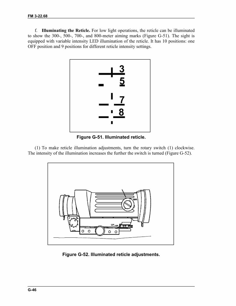
FM 3-22.68
G-46
f. Illuminating the Reticle. For low light operations, the reticle can be illuminatedto show the 300-, 500-, 700-, and 800-meter aiming marks (Figure G-51). The sight isequipped with variable intensity LED illumination of the reticle. It has 10 positions: oneOFF position and 9 positions for different reticle intensity settings.
Figure G-51. Illuminated reticle.
(1) To make reticle illumination adjustments, turn the rotary switch (1) clockwise.The intensity of the illumination increases the further the switch is turned (Figure G-52).
Figure G-52. Illuminated reticle adjustments.
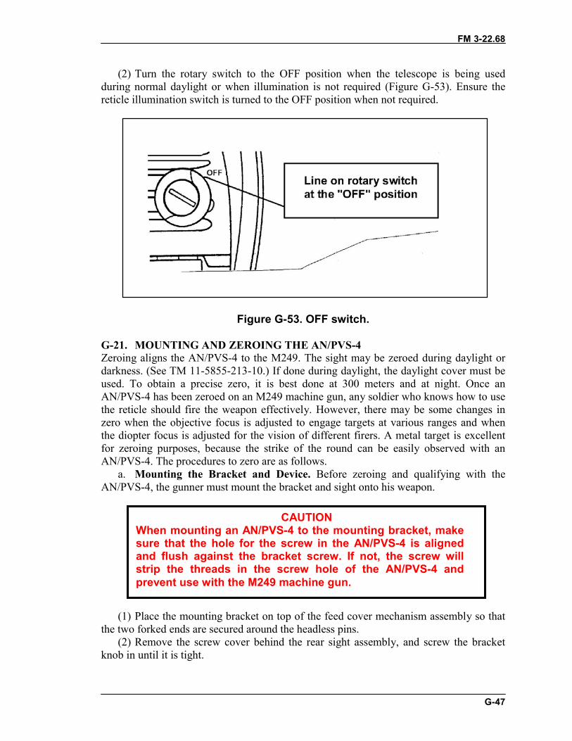
FM 3-22.68
G-47
(2) Turn the rotary switch to the OFF position when the telescope is being usedduring normal daylight or when illumination is not required (Figure G-53). Ensure thereticle illumination switch is turned to the OFF position when not required.
Figure G-53. OFF switch.
G-21. MOUNTING AND ZEROING THE AN/PVS-4Zeroing aligns the AN/PVS-4 to the M249. The sight may be zeroed during daylight ordarkness. (See TM 11-5855-213-10.) If done during daylight, the daylight cover must beused. To obtain a precise zero, it is best done at 300 meters and at night. Once anAN/PVS-4 has been zeroed on an M249 machine gun, any soldier who knows how to usethe reticle should fire the weapon effectively. However, there may be some changes inzero when the objective focus is adjusted to engage targets at various ranges and whenthe diopter focus is adjusted for the vision of different firers. A metal target is excellentfor zeroing purposes, because the strike of the round can be easily observed with anAN/PVS-4. The procedures to zero are as follows.
a. Mounting the Bracket and Device. Before zeroing and qualifying with theAN/PVS-4, the gunner must mount the bracket and sight onto his weapon.
(1) Place the mounting bracket on top of the feed cover mechanism assembly so thatthe two forked ends are secured around the headless pins.
(2) Remove the screw cover behind the rear sight assembly, and screw the bracketknob in until it is tight.
CAUTIONWhen mounting an AN/PVS-4 to the mounting bracket, makesure that the hole for the screw in the AN/PVS-4 is alignedand flush against the bracket screw. If not, the screw willstrip the threads in the screw hole of the AN/PVS-4 andprevent use with the M249 machine gun.
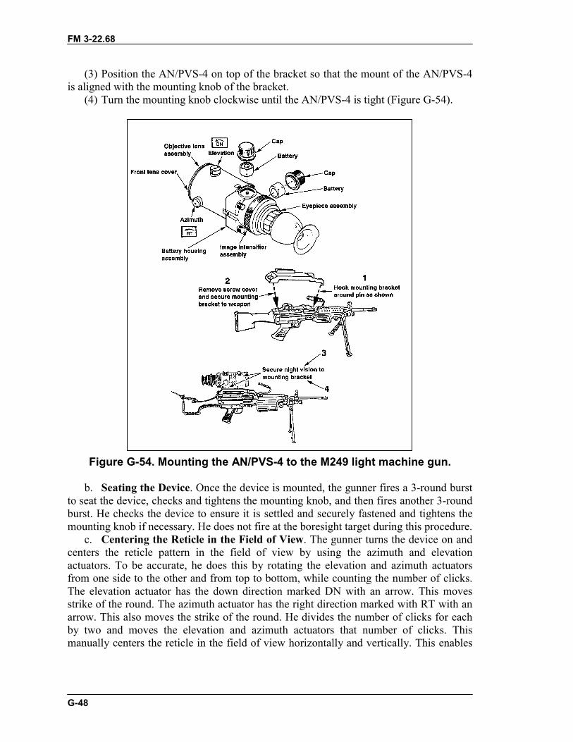
FM 3-22.68
G-48
(3) Position the AN/PVS-4 on top of the bracket so that the mount of the AN/PVS-4is aligned with the mounting knob of the bracket.
(4) Turn the mounting knob clockwise until the AN/PVS-4 is tight (Figure G-54).
Figure G-54. Mounting the AN/PVS-4 to the M249 light machine gun.
b. Seating the Device. Once the device is mounted, the gunner fires a 3-round burstto seat the device, checks and tightens the mounting knob, and then fires another 3-roundburst. He checks the device to ensure it is settled and securely fastened and tightens themounting knob if necessary. He does not fire at the boresight target during this procedure.
c. Centering the Reticle in the Field of View. The gunner turns the device on andcenters the reticle pattern in the field of view by using the azimuth and elevationactuators. To be accurate, he does this by rotating the elevation and azimuth actuatorsfrom one side to the other and from top to bottom, while counting the number of clicks.The elevation actuator has the down direction marked DN with an arrow. This movesstrike of the round. The azimuth actuator has the right direction marked with RT with anarrow. This also moves the strike of the round. He divides the number of clicks for eachby two and moves the elevation and azimuth actuators that number of clicks. Thismanually centers the reticle in the field of view horizontally and vertically. This enables
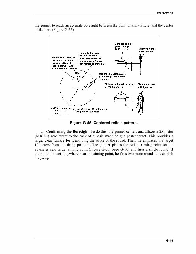
FM 3-22.68
G-49
the gunner to reach an accurate boresight between the point of aim (reticle) and the centerof the bore (Figure G-55).
Figure G-55. Centered reticle pattern.
d. Confirming the Boresight. To do this, the gunner centers and affixes a 25-meter(M16A2) zero target to the back of a basic machine gun paster target. This provides alarge, clear surface for identifying the strike of the round. Then, he emplaces the target10 meters from the firing position. The gunner places the reticle aiming point on the25-meter zero target aiming point (Figure G-56, page G-50) and fires a single round. Ifthe round impacts anywhere near the aiming point, he fires two more rounds to establishhis group.
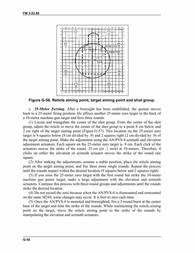
FM 3-22.68
G-50
Figure G-56. Reticle aiming point, target aiming point and shot group.
e. 25-Meter Zeroing. After a boresight has been established, the gunner movesback to a 25-meter firing position. He affixes another 25-meter zero target to the back ofa 10-meter machine gun target and fires three rounds.
(1) Locate and triangulate the center of the shot group. From the center of the shotgroup, adjust the reticle to move the center of the shot group to a point 8 cm below and2 cm right of the target aiming point (Figure G-57). This location on the 25-meter zerotarget is 9 squares below (8 cm divided by .9) and 2 squares right (2 cm divided by .9) ofthe target aiming point. Make the adjustment using the AN/PVS-4 azimuth and elevationadjustment actuators. Each square on the 25-meter zero target is .9 cm. Each click of theactuators moves the strike of the round .25 cm (or .1 inch) at 10-meters. Therefore, 4clicks on either the elevation or azimuth actuator moves the strike of the round onesquare.
(2) After making the adjustments, assume a stable position, place the reticle aimingpoint on the target aiming point, and fire three more single rounds. Repeat the processuntil the rounds impact within the desired location (9 squares below and 2 squares right).
(3) If you miss the 25-meter zero target with the first round but strike the 10-metermachine gun paster target, make a large adjustment with the elevation and azimuthactuators. Continue this process with three-round groups and adjustments until the roundsstrike the desired location.
(4) Do not record the zero because when the AN/PVS-4 is dismounted and remountedon the same M249, some changes may occur. It is best to zero each time.
(5) Once the AN/PVS-4 is mounted and boresighted, fire a 3-round burst at the centerbase of the target and note the strike of the rounds. While maintaining the reticle aimingpoint on the target, move the reticle aiming point to the strike of the rounds bymanipulating the elevation and azimuth actuators.
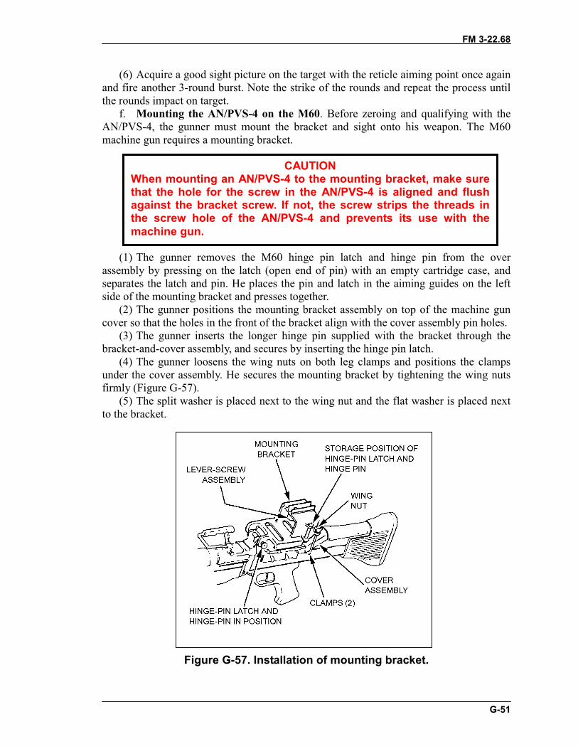
FM 3-22.68
G-51
(6) Acquire a good sight picture on the target with the reticle aiming point once againand fire another 3-round burst. Note the strike of the rounds and repeat the process untilthe rounds impact on target.
f. Mounting the AN/PVS-4 on the M60. Before zeroing and qualifying with theAN/PVS-4, the gunner must mount the bracket and sight onto his weapon. The M60machine gun requires a mounting bracket.
(1) The gunner removes the M60 hinge pin latch and hinge pin from the overassembly by pressing on the latch (open end of pin) with an empty cartridge case, andseparates the latch and pin. He places the pin and latch in the aiming guides on the leftside of the mounting bracket and presses together.
(2) The gunner positions the mounting bracket assembly on top of the machine guncover so that the holes in the front of the bracket align with the cover assembly pin holes.
(3) The gunner inserts the longer hinge pin supplied with the bracket through thebracket-and-cover assembly, and secures by inserting the hinge pin latch.
(4) The gunner loosens the wing nuts on both leg clamps and positions the clampsunder the cover assembly. He secures the mounting bracket by tightening the wing nutsfirmly (Figure G-57).
(5) The split washer is placed next to the wing nut and the flat washer is placed nextto the bracket.
Figure G-57. Installation of mounting bracket.
CAUTIONWhen mounting an AN/PVS-4 to the mounting bracket, make surethat the hole for the screw in the AN/PVS-4 is aligned and flushagainst the bracket screw. If not, the screw strips the threads inthe screw hole of the AN/PVS-4 and prevents its use with themachine gun.
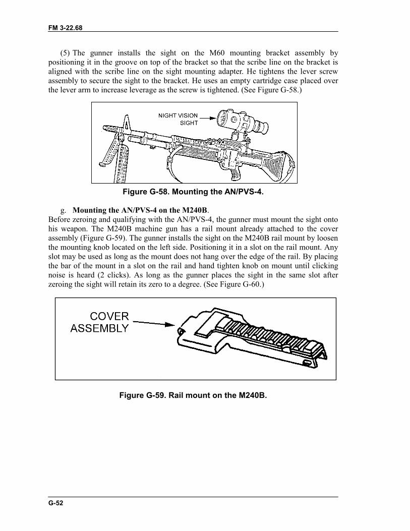
FM 3-22.68
G-52
(5) The gunner installs the sight on the M60 mounting bracket assembly bypositioning it in the groove on top of the bracket so that the scribe line on the bracket isaligned with the scribe line on the sight mounting adapter. He tightens the lever screwassembly to secure the sight to the bracket. He uses an empty cartridge case placed overthe lever arm to increase leverage as the screw is tightened. (See Figure G-58.)
Figure G-58. Mounting the AN/PVS-4.
g. Mounting the AN/PVS-4 on the M240B.Before zeroing and qualifying with the AN/PVS-4, the gunner must mount the sight ontohis weapon. The M240B machine gun has a rail mount already attached to the coverassembly (Figure G-59). The gunner installs the sight on the M240B rail mount by loosenthe mounting knob located on the left side. Positioning it in a slot on the rail mount. Anyslot may be used as long as the mount does not hang over the edge of the rail. By placingthe bar of the mount in a slot on the rail and hand tighten knob on mount until clickingnoise is heard (2 clicks). As long as the gunner places the sight in the same slot afterzeroing the sight will retain its zero to a degree. (See Figure G-60.)
Figure G-59. Rail mount on the M240B.
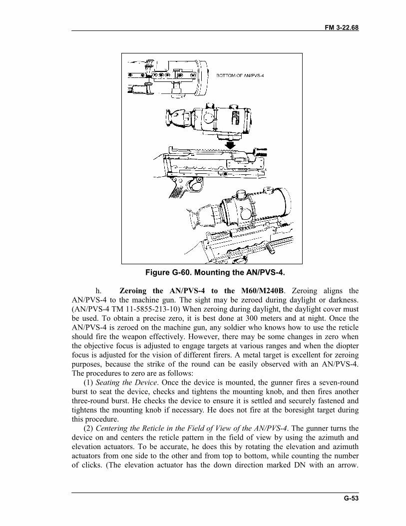
FM 3-22.68
G-53
Figure G-60. Mounting the AN/PVS-4.
h. Zeroing the AN/PVS-4 to the M60/M240B. Zeroing aligns theAN/PVS-4 to the machine gun. The sight may be zeroed during daylight or darkness.(AN/PVS-4 TM 11-5855-213-10) When zeroing during daylight, the daylight cover mustbe used. To obtain a precise zero, it is best done at 300 meters and at night. Once theAN/PVS-4 is zeroed on the machine gun, any soldier who knows how to use the reticleshould fire the weapon effectively. However, there may be some changes in zero whenthe objective focus is adjusted to engage targets at various ranges and when the diopterfocus is adjusted for the vision of different firers. A metal target is excellent for zeroingpurposes, because the strike of the round can be easily observed with an AN/PVS-4.The procedures to zero are as follows:
(1) Seating the Device. Once the device is mounted, the gunner fires a seven-roundburst to seat the device, checks and tightens the mounting knob, and then fires anotherthree-round burst. He checks the device to ensure it is settled and securely fastened andtightens the mounting knob if necessary. He does not fire at the boresight target duringthis procedure.
(2) Centering the Reticle in the Field of View of the AN/PVS-4. The gunner turns thedevice on and centers the reticle pattern in the field of view by using the azimuth andelevation actuators. To be accurate, he does this by rotating the elevation and azimuthactuators from one side to the other and from top to bottom, while counting the numberof clicks. (The elevation actuator has the down direction marked DN with an arrow.
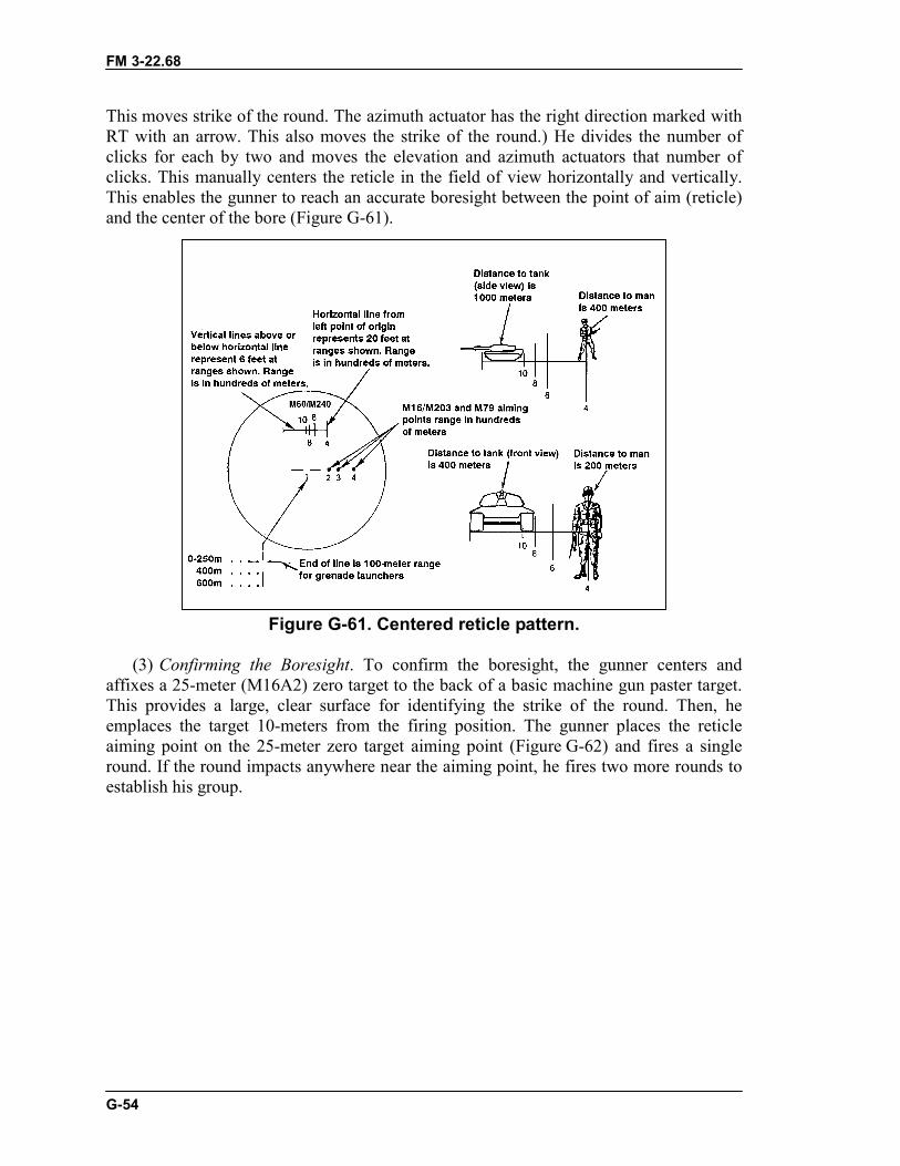
FM 3-22.68
G-54
This moves strike of the round. The azimuth actuator has the right direction marked withRT with an arrow. This also moves the strike of the round.) He divides the number ofclicks for each by two and moves the elevation and azimuth actuators that number ofclicks. This manually centers the reticle in the field of view horizontally and vertically.This enables the gunner to reach an accurate boresight between the point of aim (reticle)and the center of the bore (Figure G-61).
Figure G-61. Centered reticle pattern.
(3) Confirming the Boresight. To confirm the boresight, the gunner centers andaffixes a 25-meter (M16A2) zero target to the back of a basic machine gun paster target.This provides a large, clear surface for identifying the strike of the round. Then, heemplaces the target 10-meters from the firing position. The gunner places the reticleaiming point on the 25-meter zero target aiming point (Figure G-62) and fires a singleround. If the round impacts anywhere near the aiming point, he fires two more rounds toestablish his group.
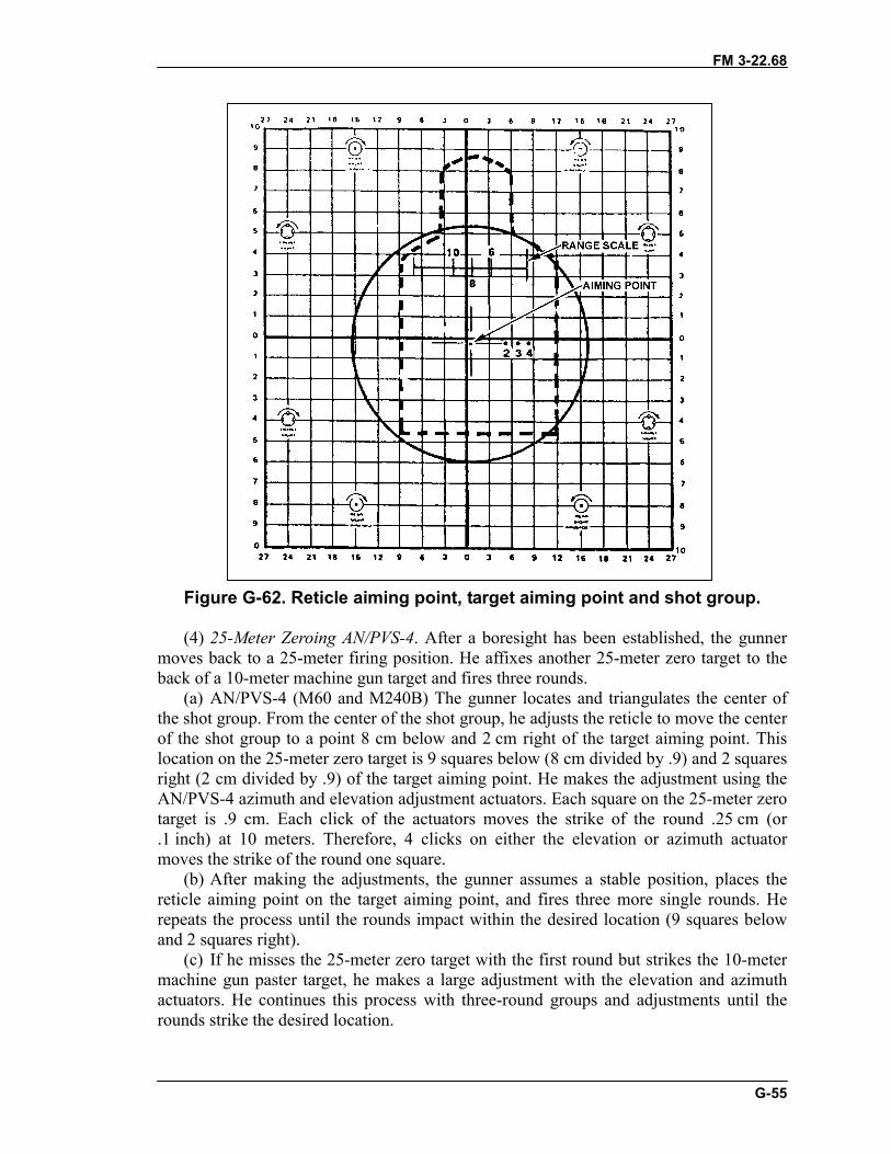
FM 3-22.68
G-55
Figure G-62. Reticle aiming point, target aiming point and shot group.
(4) 25-Meter Zeroing AN/PVS-4. After a boresight has been established, the gunnermoves back to a 25-meter firing position. He affixes another 25-meter zero target to theback of a 10-meter machine gun target and fires three rounds.
(a) AN/PVS-4 (M60 and M240B) The gunner locates and triangulates the center ofthe shot group. From the center of the shot group, he adjusts the reticle to move the centerof the shot group to a point 8 cm below and 2 cm right of the target aiming point. Thislocation on the 25-meter zero target is 9 squares below (8 cm divided by .9) and 2 squaresright (2 cm divided by .9) of the target aiming point. He makes the adjustment using theAN/PVS-4 azimuth and elevation adjustment actuators. Each square on the 25-meter zerotarget is .9 cm. Each click of the actuators moves the strike of the round .25 cm (or.1 inch) at 10 meters. Therefore, 4 clicks on either the elevation or azimuth actuatormoves the strike of the round one square.
(b) After making the adjustments, the gunner assumes a stable position, places thereticle aiming point on the target aiming point, and fires three more single rounds. Herepeats the process until the rounds impact within the desired location (9 squares belowand 2 squares right).
(c) If he misses the 25-meter zero target with the first round but strikes the 10-metermachine gun paster target, he makes a large adjustment with the elevation and azimuthactuators. He continues this process with three-round groups and adjustments until therounds strike the desired location.
FM 3-22.68
G-56
(d) He does not record the zero with the old style bracket because when theAN/PVS-4 is dismounted and remounted on the same M60, some changes may occur. Itis best to zero each time. The zero is recorded with the new rail bracket because when theAN/PVS-4 is dismounted and remounted on the same machine gun, and as long as thegunner places a mark on the rail slot the sight will have some changes. But the gunnerdoes not need to re-zero his sight to the machine gun.
(e) Once the AN/PVS-4 is mounted and boresighted, the gunner fires a three-roundburst at the center base of the target and notes the strike of the rounds. While maintainingthe reticle aiming point on the target, he moves the reticle aiming point to the strike of therounds by manipulating the elevation and azimuth actuators.
(f) The gunner acquires a good sight picture on the target with the reticle aimingpoint once again and fires another three-round burst. He notes the strike of the rounds andrepeats the process until the rounds impact on target.
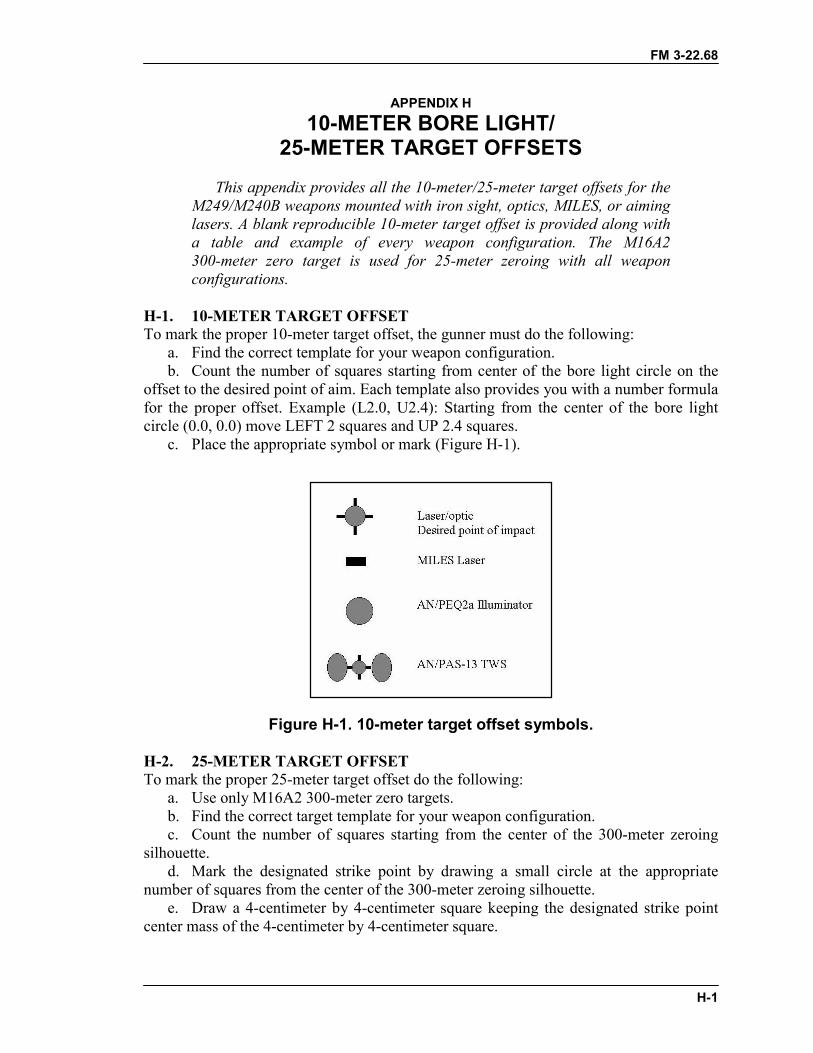
FM 3-22.68
H-1
APPENDIX H10-METER BORE LIGHT/
25-METER TARGET OFFSETSThis appendix provides all the 10-meter/25-meter target offsets for the
M249/M240B weapons mounted with iron sight, optics, MILES, or aiminglasers. A blank reproducible 10-meter target offset is provided along witha table and example of every weapon configuration. The M16A2300-meter zero target is used for 25-meter zeroing with all weaponconfigurations.
H-1. 10-METER TARGET OFFSETTo mark the proper 10-meter target offset, the gunner must do the following:
a. Find the correct template for your weapon configuration.b. Count the number of squares starting from center of the bore light circle on the
offset to the desired point of aim. Each template also provides you with a number formulafor the proper offset. Example (L2.0, U2.4): Starting from the center of the bore lightcircle (0.0, 0.0) move LEFT 2 squares and UP 2.4 squares.
c. Place the appropriate symbol or mark (Figure H-1).
Figure H-1. 10-meter target offset symbols.
H-2. 25-METER TARGET OFFSETTo mark the proper 25-meter target offset do the following:
a. Use only M16A2 300-meter zero targets.b. Find the correct target template for your weapon configuration.c. Count the number of squares starting from the center of the 300-meter zeroing
silhouette.d. Mark the designated strike point by drawing a small circle at the appropriate
number of squares from the center of the 300-meter zeroing silhouette.e. Draw a 4-centimeter by 4-centimeter square keeping the designated strike point
center mass of the 4-centimeter by 4-centimeter square.
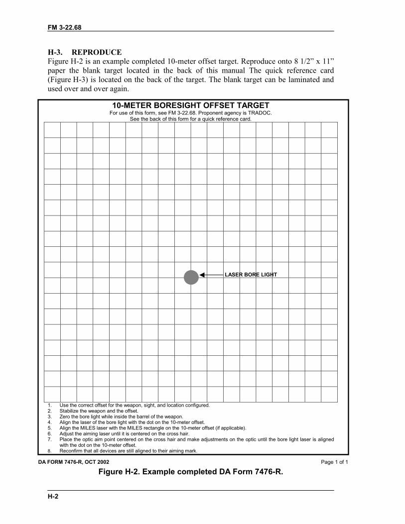
FM 3-22.68
H-2
H-3. REPRODUCEFigure H-2 is an example completed 10-meter offset target. Reproduce onto 8 1/2” x 11”paper the blank target located in the back of this manual The quick reference card(Figure H-3) is located on the back of the target. The blank target can be laminated andused over and over again.
10-METER BORESIGHT OFFSET TARGETFor use of this form, see FM 3-22.68. Proponent agency is TRADOC.
See the back of this form for a quick reference card.
1. Use the correct offset for the weapon, sight, and location configured.2. Stabilize the weapon and the offset.3. Zero the bore light while inside the barrel of the weapon.4. Align the laser of the bore light with the dot on the 10-meter offset.5. Align the MILES laser with the MILES rectangle on the 10-meter offset (if applicable).6. Adjust the aiming laser until it is centered on the cross hair.7. Place the optic aim point centered on the cross hair and make adjustments on the optic until the bore light laser is aligned
with the dot on the 10-meter offset.8. Reconfirm that all devices are still aligned to their aiming mark.
DA FORM 7476-R, OCT 2002 Page 1 of 1
Figure H-2. Example completed DA Form 7476-R.
LASER BORE LIGHT

FM 3-22.68
H-3
WPN ACCESSORY MOUNTRANGE
ZEROEDTO
ZEROTARGETOFFSET
BORESIGHTTARGETOFFSET
MILESOFFSET
M249 IRON SIGHTS NA 400m NA TBD 1.9L/.5UM249 MGO IFTC RAIL 400m TBD 0.0/7.9U 1.9L/.5UM249 MGO TWS BRACKET 400m TBD 0.0/2.15U 1.9L/.6UM249 AN/PAQ-4C TWS BRACKET TOP 400m 0.5R/1.5U 1.85L/7.7U 1.9L/.5UM249 AN/PAQ-4C AN/PVS4 BRACKET 400m 2.5R/1.5D 4.1L/6.1U 1.9L/.5U
M249 AN/PAQ-4C INSIGHT RAIL GRABBERWITH IFTC 400m TBD 1.75L/4.69U 1.9L/.5U
M249 AN/PAQ-4C PICATINNEY RAILGRABBERWITH IFTC 400m 1.75R/0.0 1.75L/5.39U 1.9L/.5U
M249 AN/PAQ-4C INSIGHT RAIL GRABBERFORWARD RAILS RIGHT 400m 5.9R/9.6D 5.9R/4.0D 1.9L/.5U
M249 AN/PAQ-4C INSIGHT RAIL GRABBERFORWARD RAILS LEFT 400m 6.0R/13.3D 6.OR/8.3D 1.9L/.5U
M249 AN/PAQ-4C PICATINNY RAIL GRABBERWITH AL SPACER FORWARDRAILS RIGHT
400m 7.7R/9.6D 7.7R/4.0D 1.9L/.5U
M249 AN/PAQ4-C PICATINNY RAIL GRABBERFORWARD RAILS LEFT 400m 7.6R/13.3D 7.6R/8.3D 1.9L/.5U
M249 AN/PEQ-2A TWS BRACKET TOP 400m 1.8L/2.7D 1.8R/7.95U 1.9L/.5UM249 AN/PEQ-2A AN/PVS4 BRACKET WITH
SPACER 400m 5.0R/4.0D .45L/6.5U 1.9L/.5U
M249 AN/PEQ-2A INSIGHT RAIL GRABBERWITH IFTC 400m 2.0L/1.5U 1.95R/4.79U 1.9L/.5U
M249 AN/PEQ-2A PICATINNEY RAIL GRABBERWITH IFTC 400m 2.0L/0.5D 1.95R/6.49U 1.9L/.5U
M249 AN/PEQ-2A INSIGHT RAIL GRABBERFORWARD RAILS RIGHT 400m 6.1R/13.2D 6.1R/7.6D 1.9L/.5U
M249 AN/PEQ-2A INSIGHT RAIL GRABBERFORWARD RAILS LEFT 400m 6.0R/9.4D 6.0R/4.4D 1.9L/.5U
M249 AN/PEQ-2A PICATINNY RAIL GRABBERWITH AL SPACER FORWARDRAILS RIGHT
400m 7.8R/13.2D 7.8R/7.6D 1.9L/.5U
M249 AN/PEQ-2A PICATINNY RAIL GRABBERFORWARD RAILS LEFT 400m 7.6R/9.4D 7.6R/4.4D 1.9L/.5U
M249 AN/PVS-4 IFTC TOP WITH SPACER 400m 0.0/4.3D 0.0/10.00U 1.9L/.5UM249 AN/PVS-4 AN/PVS-4 BRACKET 400m 2.5R/4.9D 2.25L/11.25U 1.9L/.5UM249 AN/PAS-13 IFTC TOP 400m 0.0/2.75D 0.0/8.6U 1.9L/.5UM249 AN/PAS-13 TWS BRACKET 400m 0.0/5.5D 0.0/10.05U 1.9L/.5U
M240B IRON SIGHTS NA 500m TBD TBD 1.9L/.5UM240B MGO FEEDTRAY COVER RAIL 500m NA 0.0/0.0 5.0R/4.1DM240B AN/PAQ-4C PICATINNEY RAIL GRABBER
TOP 500m 1.75R/2.2D 1.5L/3.5U 5.0R/4.1D
M240B AN/PEQ-2A INSIGHT RAIL GRABBER TOP 500m 2.0R/1.5D 1.7R/3.71U 5.0R/4.1DM240B AN/PAQ-4C INSIGHT RAIL GRABBER
FORWARD RAILS RIGHT 500m TBD TBD 5.0R/4.1D
M240B AN/PAQ-4C INSIGHT RAIL GRABBERFORWARD RAILS LEFT 500m 6.2R/16.8D 6.2R/8.1D 5.0R/4.1D
M240B AN/PAQ-4C PICATINNY RAIL GRABBERFORWARD RAILS RIGHT 500m TBD TBD 5.0R/4.1D
M240B AN/PAQ-4C PICATINNY RAIL GRABBERFORWARD RAILS LEFT 500m 7.9R/16.8D 7.9R/8.1D 5.0R/4.1D
M240B AN/PEQ-2A INSIGHT RAIL GRABBERFORWARD RAILS RIGHT 500m TBD TBD 5.0R/4.1D
M240B AN/PEQ-2A INSIGHT RAIL GRABBERFORWARD RAILS LEFT 500m 6.2R/12.8D 6.2R/4.1D 5.0R/4.1D
M240B AN/PEQ-2A PICATINNY RAIL GRABBERFORWARD RAILS RIGHT 500m TBD TBD 5.0R/4.1D
M240B AN/PEQ-2A PICATINNY RAIL GRABBERFORWARD RAILS LEFT 500m 7.9R/12.8D 7.9R/4.1D 5.0R/4.1D
M240B AN/PVS-4 FEEDTRAY COVER RAILPICATINNY RAIL GRABBERWITH SPACER
500m 0.0/6.2D 0.0/6.0U 5.0R/4.1D
M240B AN/PAS-13 FEED TRAY COVER 500m 0.0/2.3U 0.0/8.0U 5.0R/4.1D
DA FORM 7476-R, OCT 2002 Page 1 of 2
Figure H-3. Quick reference card is included on back of DA Form 7476-R.

FM 3-22.68
Glossary-1
GLOSSARY
AAR after-action reportAR Army regulationARTEP Army Training and Evaluation Program
BFA blank firing attachment
CLP cleaner, lubricant, preservativecm centimetersCO company
DA Department of the ArmyDODAC Department of Defense Ammunition Code
EST engagement skills trainer
FM field manualFPF final protective fireFPL final protective lineFSN Federal stock numberFTX field training exercise
GTA graphic training aid
HMMWV high-mobility, multipurpose wheeled vehicle
IAW in accordance withIET initial entry trainingIOAC Infantry officer's advanced courseIOBC Infantry officer's basic courseinstr instruction
LAW lubricating oil, arctic weatherLFX live-fire exerciseLRA local reproduction authorizedLSA lubricating oil, semifluid, automatic weaponsLTA local training area
m meterMETL mission-essential task list

FM 3-22.68
Glossary-2
MGO machine gun opticMILES multiple-integrated laser engagement systemmm millimetermph miles per hourMPRC multipurpose range complexMTA major training areaMTP mission training planMWTS medium-weapon thermal sight
N/A not applicableNATO North Atlantic Treaty OrganizationNBC nuclear, biological, and chemicalNCO noncommissioned officerNCOES Noncommissioned Officer Education SystemNCOIC noncommissioned officer in chargeNSN national stock numberNVD night vision device
OIC officer in charge
PAM pamphletPDF principal direction of firePLT platoonPOPP Pull, Observe, Push, and Press (memory aid for immediate action)prac practice
qual qualification
RD round
sec secondSM soldier's manualSMCT soldier's manual of common tasksSOP standing operating proceduressqd squadSTP soldier's training publicationSTRAC standards in training commissionSTX situational training exercise
T&E traversing and elevatingTC training circular

FM 3-22.68
Glossary-3
TM technical manualTOE table of organization and equipmentTPIAL target pointer/illuminator/aiming lightTRADOC US Army Training and Doctrine Command
US United States
FM 3-22.68
References-1
REFERENCES
SOURCES USEDThese are the sources quoted or paraphrased in this publication.
ARTEP 7-8-MTP Mission Training Plan for the Infantry Rifle Platoon andSquad. 30 September 1988.
ARTEP 7-8-DRILL Drills for the Infantry Rifle Platoon and Squad.3 November 1993.
FM 7-8 Infantry Platoon and Squad. 22 April 1992.
FM 21-26 Map Reading and Land Navigation. 7 May 1993.
DOCUMENTS NEEDEDThese documents must be available to the intended uses of this publication.
AR 385-63 Policies and Procedures for Training, Target Practice andCombat. 15 October 1983.
DA Form 2404 Equipment Inspection and Maintenance Worksheet.April 1979.
DA Form 5517-R Standard Range Card (LRA). February 1986.
DA Form 85-R Scorecard for M249, M60/M240B Machine Guns. October2002.
DA Form 7476-R 10-Meter Boresight Offset Target. October 2002.
DA Pam 25-30 Army Electronic Library. 1 July 2002.
DA Pam 350-38 Training Standards for Weapon Training. September 1990.
*FM 3-5 NBC Decontamination. 23 July 1992.
*FM 21-60 Visual Signals. 30 September 1987.
STP 21-24-SMCT Soldier's Manual of Common Tasks (Skill Levels 2-4).1 October 2001.
*This source was also used to develop this publication.

FM 3-22.68
References-2
*TC 25-8 Training Ranges. 25 February 1992.
TM 9-1005-319-10 Operator's Manual List for Rifle 5.56-mm, M16A2. 1 October1998.
*TM 9—1005-201-10 Operator’s Manual Machine Gun, 5.56-mm, M249 w/Equip.26 July 1991.
*TM 9-1005-224-10 Operator's Manual for Machine Gun, 7.62-mm, M60, W/E;Mount, Tripod, Machine Gun, 7.62-mm, M122. 2 April 1998.
*TM 9-1005-313-10 Operator’s Manual for Machine Gun, 7.62-mm, M240B, W/E;Flex-mount, Tripod, Machine Gun, 7.62-mm, M122A1.19 July 1996.
*TM 9-1300-200 Ammunition General. 3 October 1969.
*TM 11-5855-213-10 Operator's Manual Night Vision Sight, Individual ServedWeapon, AN/PVS-4. 1 February 1993.
INTERNET WEB SITES
U.S. Army Publishing Agencyhttp://www.usapa.army.mil
Army Doctrine and Training Digital Libraryhttp://www.adtdl.army.mil
*This source was also used to develop this publication.

FM 3-22.68
Index-1
INDEX10-meter
firing, 4-1, 4-21, 4-34, 4-44, 6-3, 6-8,A-3
qualification, 1-30, 2-25, 3-30, 4-22,4-34
10-Meter Boresight Offset Target, DAForm 7476-R, H-2 (illus)
adjusted aiming point method, 4-14,4-15 (illus), 4-47
adjustment of fire, 4-1, 4-16advanced Gunnery, 5-1, 5-37, 6-3after firing, 1-8, 2-10, 3-9air defense, C-1, C-2aim, 4-5ammunition, 5.56-mm, 1-5, 4-41ammunition, 7.62-mm, 2-7, 3-5
ball, 1-6, 2-7, 3-6AN/PAS-13, medium weapon thermal
sight, 4-25, G-23AN/PEQ-2A, target pointer/illuminator/
aiming light laser system, G-14AN/PVS-4, aiming light, 4-26, 6-10, G-6AN/PVS-7, 4-27AN/PVS-7/B/C/D, goggles, 4-25, G-6AN/PVS-14, goggles, 4-25, G-6appearance-of-objects method, 4-17,
5-16application of fire, 5-13, 6-1, 6-5area target, 5-21, 5-27, 6-5 to 6-10, 6-23,
6-34arm-and-hand signals, 5-21, 5-25, 5-28assault fire exercise, 5-35
barrel group, 1-15, 2-14, 3-13, B-2basic gunnery (M249, M60/M240B),
4-1, 4-24, 4-34basic marksmanship, 4-1, 4-32, 6-8beaten zone, 5-2, 5-13, 5-27, 5-34, 6-1,
A-1bipod group, 1-15, 2-14, 3-13blank firing attachment, 1-8, 2-8, 3-7bipod positioning, 1-29, 2-27, 3-29bore light, G-1
breath control, 4-4, 4-9buttstock and buffer assembly group,
1-14, 2-13, 3-11cadre coaches, 6-1chambering, 1-24, 2-22, 3-23characteristics of fire, 5-1classes of fire
ground fire, 5-2grazing, 5-2plunging, 5-2
target, 5-3frontal fire, 5-3flanking, 5-3oblique fire, 5-3enfilade, 5-3
machine gunfixed, 5-4searching, 5-4traversing, 5-4free gun, 5-4
cleaning, 1-16, 2-17, 3-16, B-4, D-2clock system, 4-15coaches, 6-1cocking, 1-21, 2-22, 3-21, 4-3, 5-18,
B-3, B-4cold weapon, 1-31, 2-33, 3-32combat fire, 4-5combat load, 4-12combat readiness, 6-1components, 1-3, 2-3, 2-12, 2-16, 3-3,
4-2concentration of fire, 5-6cone of fire, 5-1, 5-10 (illus)corrections, 1-25, 2-24, 3-25, 5-26, B-5cycle of functioning, 1-24, 2-23, 3-24
DA Form 85A-R, Scorecard for M249,M60/M240B Machine Guns,4-54 (illus)
DA Form 7476-R, 10-Meter BoresightOffset Target, H-2 (illus)
danger space, 5-2dead space, 5-16deep target, 6-5, 6-9 to 6-13, B-1, B-5

FM 3-22.68
Index-2
defense, 5-14, E-1description, 1-1, 2-1, 3-1, 5-25, 5-28destruction, 1-30, 2-31, 3-30destruction procedures, 1-34, 2-33, 3-33direct lay, 4-14direction of fire, 6-13disassembly, 1-11, 1-16, 2-12, 3-12, 6-4,
B-1dry-fire exercises, 4-7, 4-18dry-fire proficiency examination, 4-19,
B-1during firing, 1-24, 2-23, 3-24, 5-13,
5-31, D-1during NBC conditions, 1-22, 2-22,
3-23, 4-19
effects of wind, 4-15ejecting, 6-5elevation, 1-5, 2-6, 3-5, 4-5, 4-13, 5-4,
B-5employment, E-1enfilade fire, 5-3, 5-11examination, dry-fire proficiency, 4-19,
B-1exercise, field firing, 4-33, 4-44, 4-64extracting, 1-24, 2-23, 3-24feeding, 1-24, 2-23, 3-4, 3-29field firing exercise, 4-33, 4-44, 4-64fighting positions 4-7
bipod-supported, 4-6, 4-11, 4-34final protective fire, 5-15final protective line, 5-15fire
characteristics of, 5-1enfilade, 5-4 (illus)classes of, 5-2 (illus), 5-3, 5-4, 6-9oblique, 5-4 (illus)plunging, 5-2predetermined, 5-16searching, sector of, 5-4, 6-4, 6-13
traversing, 5-4traversing and searching, 5-4
fire commands, 4-1, 4-2, 4-5, 4-17, 4-35,4-40, 5-27
abbreviated, 5-25initial, 5-21
subsequent, 4-8, 5-21fire control, 5-17, 5-21, 5-24firing positions, 4-6, 5-38, C-1
bipod-supported, 4-6 to 4-10hip, 5-39underarm, 5-38
Firing Table I, 4-39, 4-40 to 4-46Firing Table II, 4-47 to 4-52Firing Table III, 4-53 to 4-58Firing Table IV, 4-61 to 4-68Firing Table V, 4-69,4-74fixed fire, 5-4flanking fire, 5-3front sight, 1-5, 2-26, 2-27, 3-32, 4-28,
4-34, 5-32function check, 1-23, 2-22, 3-28functioning, sequence of
chambering, 1-26, 2-24, 3-30cocking, 1-26, 2-24, 3-30, 4-3, 4-18,
5-5, B-3, B-4ejecting, 1-26, 2-24, 3-30extracting, 1-26, 2-24, 3-30feeding, 1-26, 2-24, 3-30firing, 1-26, 2-24, 3-30locking, 1-26, 2-24, 3-30, 4-3, 6-18,
B-3unlocking, 1-26, 2-24, 3-30, 6-5
gas cylinder group, 2-10, 2-17, 3-6, B-2grazing fire, 6-2, 6-13 to 6-16grid square overlay, 5-22, 5-25
handguard group, 2-8, B-2
immediate action, 1-38M249, 2-33M60, 2-39M240B, 4-3, 5-18, 5-33, B-3
lateral distance measure, 6-29linear target, 5-21, 6-5, 6-8 to 6-13live-fire exercise, 5-1, 5-2, 5-17, 5-25,
5-27lubrication, 1-8, 2-1, 2-12, 2-16, 4-2
FM 3-22.68
Index-3
maintenance, 1-9, 2-1, 2-12, 2-16, 2-21,4-1, 4-2, 5-25, A-1
malfunctions, 1-7, 2-21, 4-1, 5-33, B-4marksmanship
advanced, 5-1, 5-17, 6-1basic, 5-1, 5-2, 5-25fundamentals
aiming, 3-5, 4-3, 5-5, 5-9, 5-13,5-18, 5-25, 5-39, 6-8, 6-11 to6-15, 6-32, B-5
marksmanship, fundamentals ofaim, 4-5breath control, 4-5steady position, 4-4, 5-11 to 5-14trigger control, 4-5, 5-5, 5-28preliminary, 5-1 to 5-6, A-1
maximum ordinate, 5-1 (illus)moving targets, fundamentals of, 5-10,
5-13
night firing, fundamentals of, 5-9, 5-10,D-1
offense, E-1operating rod group, 2-5, 2-6, 2-20, 4-4,
B-2
peep sight, 1-4, 3-5, 5-6, 5-18, 5-25plunging fire, 6-2point target, 5-21, 5-27, 6-3predetermined fires, 5-5, 6-13preliminary marksmanship, (see
marksmanship)principal direction of fire, 6-13
qualification, 5-2, 5-5, 5-21, 5-27 to5-45, A-1 to A-3
range card, 5-5, 6-13 to 6-21range determination, 5-2, 5-33, 6-26range layout, 5-20range safety, A-2, D-1rate of fire, 1-1, 6-5 to 6-7, 6-14, 6-20 to
6-25, B-5cyclic, 6-7sustained, 6-14, 6-23, B-6
rear sight, 1-4, 2-12, 3-2, 3-5, 5-6, 5-10,5-17, 5-28, 5-34 to 5-39, 6-14, 6-23, 6-32, B-5
receiver group, 2-5, 2-11, 2-16, 4-4, B-2remedial action, 4-3, 4-4, B-1, B-3remedial training, 5-29
safety, 1-1, 1-5, 2-1, 2-12, 2-20, 3-1, 3-3,4-2, 5-17, 5-20, 5-28, 6-30, 6-34,B-1, B-3, B-4, D-1
searching fire, 6-4, 6-9sector of fire, 6-13 to 6-17
primary, 6-14secondary, 6-13
Scorecard for M249, M60/M240BMachine Guns, DA Form 85-R,4-54 (illus)
sights, 1-1front, 1-4, 2-6, 2-11, 2-18, 5-6, 5-13,
5-25, 5-28, 5-34, 6-32peep, 1-4, 3-5, 5-6, 5-18, 5-25rear, 1-4, 2-12, 3-2, 3-5, 5-6, 5-17,
5-28, 5-34, 5-39, 6-14, 6-23,6-32, B-5
settingscorrections, 3-5, 5-14
stoppages, 1-1, 1-8, 2-16, 2-21, 3-3, 4-1,A-2
target analysis, 5-23target engagement
during limited visibility, 6-12targets
area, 5-21, 5-27, 6-5 to 6-10, 6-23,6-34
deep, 6-5, 6-9 to 6-13, B-1, B-5linear, 5-21, 6-5, 6-8 to 6-13point, 5-21, 5-27, 6-5, 6-30
trainer assessment, 7-1trainer certification, 7-8training
aids and devices, F-1remedial, 5-29strategy, 5-1, 5-2, 5-3
train-the-trainer program, 6-1trajectory, 5-16, 6-1, 6-2

FM 3-22.68
Index-4
transition firing, 5-1, 5-20, 5-24, 5-33,5-38
traverse and search,fundamentals of, 5-13, 5-27, 5-30,
6-23traversing and searching fire, 6-4, 6-9traversing fire, 6-5trigger mechanism group, 2-17, B-2
unit training, A-1unloading, 3-1, 3-3, 5-18, B-1
windage correction, 5-14, B-4
zeroing, 1-4, 3-5, 5-1, 5-6, 5-21, 5-25 to5-28, 5-33, 5-38, 6-30, A-2, B-1,B-4
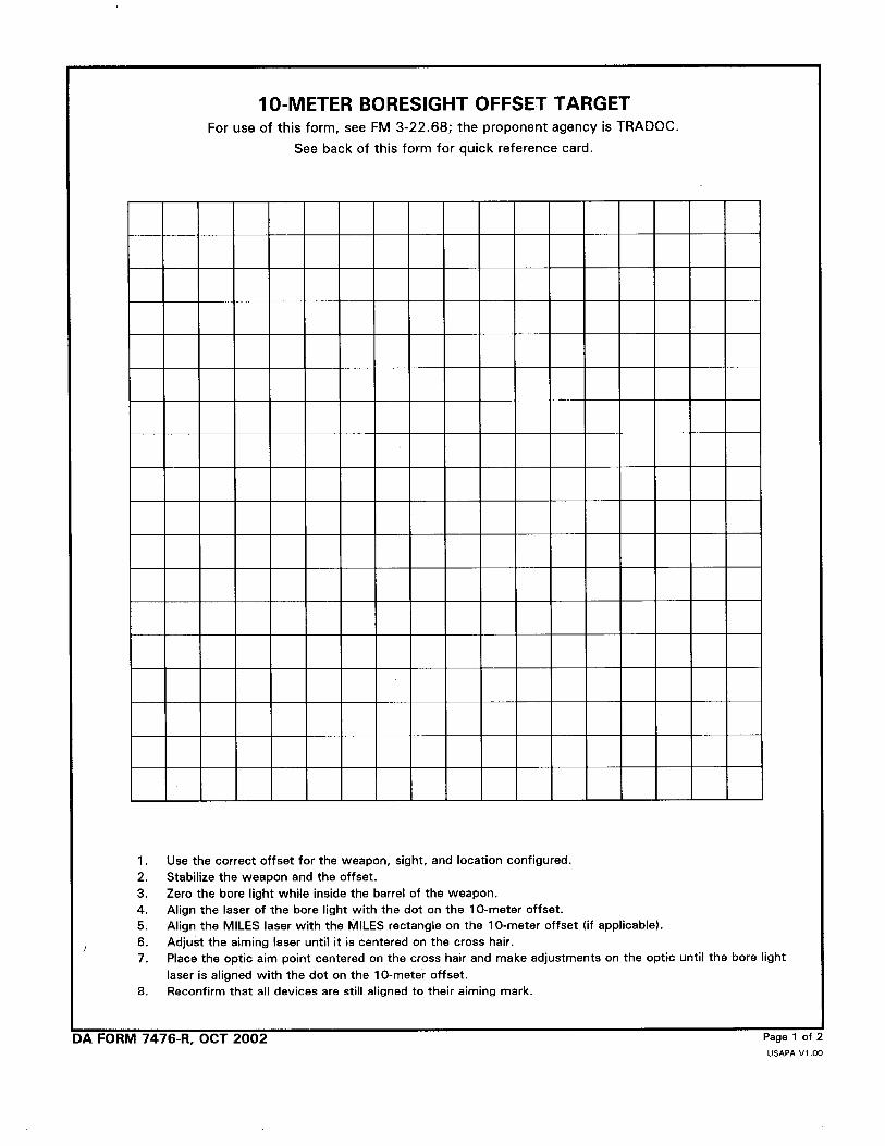


FM 3-22.6831 JANUARY 2003
By Order of the Secretary of the Army:
Official:
0300801
DISTRIBUTION:
Active Army, Army National Guard, and U. S. Army Reserve: To be distributedin accordance with the initial distribution number 115879, requirements forFM 3-22.68.
ERIC K. SHINSEKIGeneral, United States Army
Chief of Staff
JOEL B. HUDSONAdministrative Assistant to the
Secretary of the Army

PIN: 080580-000