Embed Size (px)
DESCRIPTION
Critical Analysis of the Campo Volantin Footbridge
Citation preview
A CRITICAL ANALYSIS OF THE CAMPO VOLANTIN FOOTBRIDGE
BILBAO, SPAIN E. M. Smith
1
1Undergraduate Student – University of Bath
Abstract: This paper explores the aesthetics, structural performance and design issues of the Campo Volantin
Footbridge, Bilbao. Particular emphasis is placed on the context of the bridge within a declining urban
environment, highlighting the effect symbolic infrastructure can have on an urban or peripheral space. A
simplified structural analysis is carried out for the arched span and its concrete abutments using British
Standards for Steel, Concrete and Composite Materials. The practicalities of the Footbridge are also discussed,
posing the question of whether the structure has been intelligently designed.
Keywords: Campo Volantin Footbridge, inclined arch, curved deck, symbolic infrastructure
1 Introduction
Santiago Calatrava, the Catalan born Architect
and Civil Engineer is well known throughout the world
for combining the knowledge and skills of his two
professions to represent engineering as a useful art.
Since establishing his offices in the 1980‟s, he has
created structures full of character, from his signature
cable stayed bridges to railway stations, airports and
skyscrapers. Beginning his career as a bridge engineer
in 1984 with the Bach de Roda built for the Olympics
in Barcelona, Calatrava has established his name by
designing structures which prioritise form but have
well defined function. He has frequently produced
structures to signify occasions; the aforementioned
Bach de Roda, the Puente del Alamillo for the 1992
World Exposition and the recently completed
Jerusalem Chords Bridge in honour of Israel‟s 60th
anniversary. This reputation for designing significant
and influential structures can be seen in the subject of
this paper; the Puente del Campo Volantin or Campo
Volantin Footbridge (see Fig. 1).
Known locally as „Zubizuri ‟or „White Bridge‟, the
expressive footbridge was part of a multimillion pound
plan to reinvigorate the city of Bilbao to coincide with
its 700th
anniversary; it explores the civic and social
impact that significant infrastructure can have on a
declining urban environment.
The Campo Volantin footbridge is situated
approximately 900m upstream of Frank Gehry‟s
Guggenheim Museum, spanning 75 metres across the
Nervión, a river which meanders through Bilbao on its
way to the Bay of Biscay. The Bridge and the
Guggenheim, along with Norman Foster‟s underground
line and Calatrava‟s new airport terminal are all
landmark features representing the regenerative
ambitions of the Basque city.
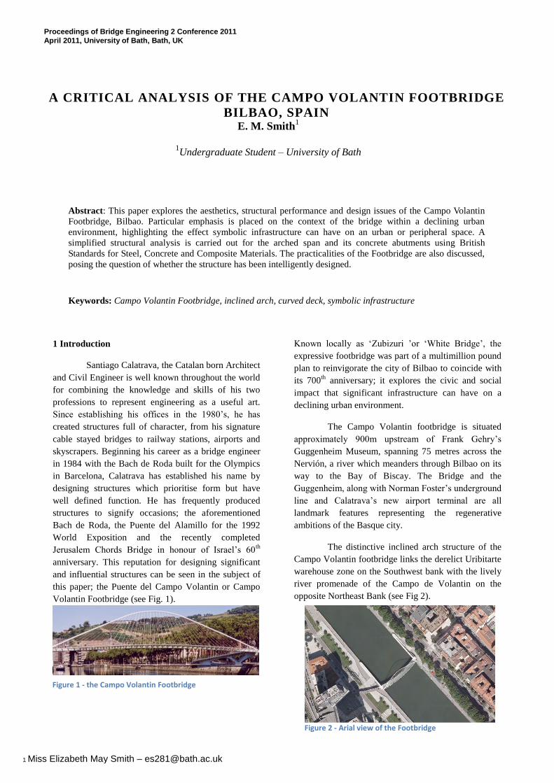
The distinctive inclined arch structure of the
Campo Volantin footbridge links the derelict Uribitarte
warehouse zone on the Southwest bank with the lively
river promenade of the Campo de Volantin on the
opposite Northeast Bank (see Fig 2).
Proceedings of Bridge Engineering 2 Conference 2011
April 2011, University of Bath, Bath, UK
Figure 1 - the Campo Volantin Footbridge
Figure 2 - Arial view of the Footbridge
1 Miss Elizabeth May Smith – [email protected]
Its introduction was intended to symbolise the
infrastructural improvements being made to the disused
areas along the river left by the now obsolete maritime
industry. Like the Trinity Bridge in Salford, the „white
bridge‟ has a civic agenda, the colour representing a
revival and the form a city renewal, bridging a gap
between two previously socially divided parts of
Bilbao. It is wholly representative of Calatrava‟s
thoughts on peripheral and urban spaces [1].
The Campo Volantin footbridge,
commissioned by the local authorities, was the second
proposed design for the site, intended as a replacement
for that designed as „Uribitarte Bridge‟ [1] which came
into trouble under its previous commissioners. The
arch is very much a Calatrava speciality, whether
braced (Bach de Roda), vertical (Lusitania Bridge), or
as here inclined. Its form is easy to control structurally
so can be repeatedly changed and adapted, often
resulting in a hugely symbolic structure when
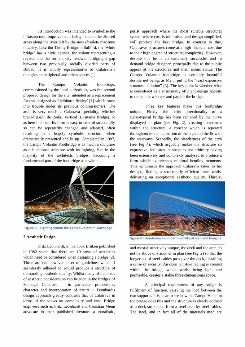
dramatically presented and lit up. Completed in 1997,
the Campo Volantin Footbridge is as much a sculpture
as a functional structure with its lighting, like in the
majority of the architects bridges, becoming a
fundamental part of the footbridge as a whole.
2 Aesthetic Design
Fritz Leonhardt, in his book Brüken published
in 1982 stated that there are 10 areas of aesthetics
which need be considered when designing a bridge [2].
These are not however a set of guidelines which if
seamlessly adhered to would produce a structure of
outstanding aesthetic quality. Whilst many of the areas
of aesthetic consideration can be seen in the bridges of
Santiago Calatrava – in particular proportions,
character and incorporation of nature – Leonhardts
design approach greatly contrasts that of Calatrava in
terms of the views on complexity and cost. Bridge
engineers such as Fritz Leonhardt and Christian Menn
advocate in their published literature a moralistic,
purist approach where the most suitable structural
system where cost is minimised and design simplified,
will produce the best bridge. In contrast to this,
Calatravas structures come at a high financial cost due
to their high degree of structural complexity. However,
despite this he is an extremely successful and in
demand bridge designer, principally due to the public
appeal of his structures and their iconic status. The
Campo Volantin footbridge is certainly beautiful
despite not being, as Menn put it, the “least expensive
structural solution” [3]. The key point is whether what
is considered as a structurally efficient design appeals
to the public who use and pay for the bridge.
Three key features make this footbridge
unique. Firstly, the strict directionality of a
stereotypical bridge has been replaced by the curve
displayed in plan (see Fig. 2), creating movement
within the structure; a concept which is repeated
throughout in the inclination of the arch and the flow of
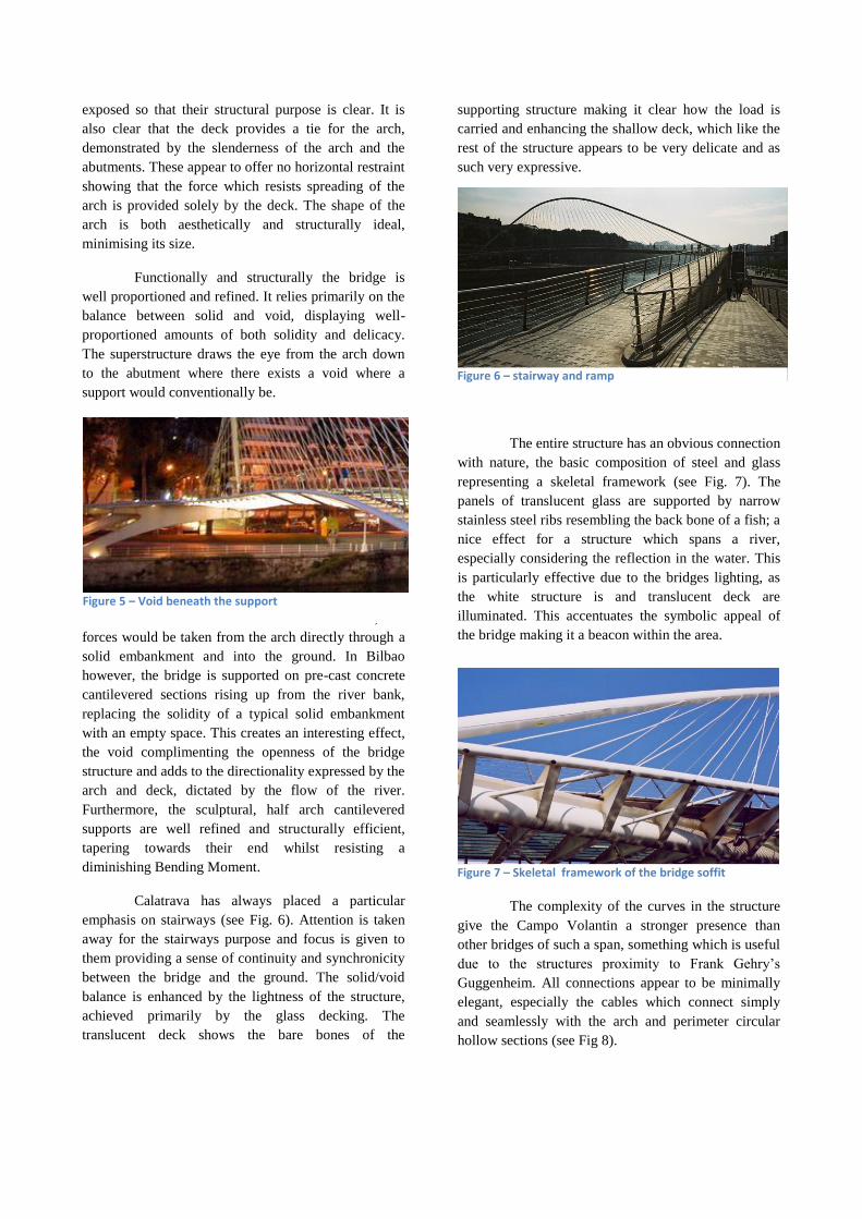
the stairways. Secondly, the slenderness of the arch
(see Fig 4), which arguably makes the structure so
expressive, indicates its shape is not arbitrary having
been extensively and complexly analysed to produce a
form which experiences minimal bending moments.
This epitomises the approach Calatrava takes to his
designs, finding a structurally efficient form whilst
delivering an exceptional aesthetic quality. Thirdly,
and most distinctively unique, the deck and the arch do
not lie above one another in plan (see Fig. 2) so that the
longer set of steel cables pass over the deck, installing
a sense of security. An open tent-like feeling is created
within the bridge, which whilst being light and
permeable, creates a stable three-dimensional space.
A principal requirement of any bridge is
fulfilment of function, carrying the load between the
two supports. It is clear to see how the Campo Volantin
footbridge does this and the structure is clearly defined
as a deck suspended from a steel arch by steel cables.
The steel, and in fact all of the materials used are
Figure 3 – Lighting within the Campo Volantin Footbridge
Figure 4 - Slenderness and permeability of arch and hangers
exposed so that their structural purpose is clear. It is
also clear that the deck provides a tie for the arch,
demonstrated by the slenderness of the arch and the
abutments. These appear to offer no horizontal restraint
showing that the force which resists spreading of the
arch is provided solely by the deck. The shape of the
arch is both aesthetically and structurally ideal,
minimising its size.
Functionally and structurally the bridge is
well proportioned and refined. It relies primarily on the
balance between solid and void, displaying well-
proportioned amounts of both solidity and delicacy.
The superstructure draws the eye from the arch down
to the abutment where there exists a void where a
support would conventionally be.
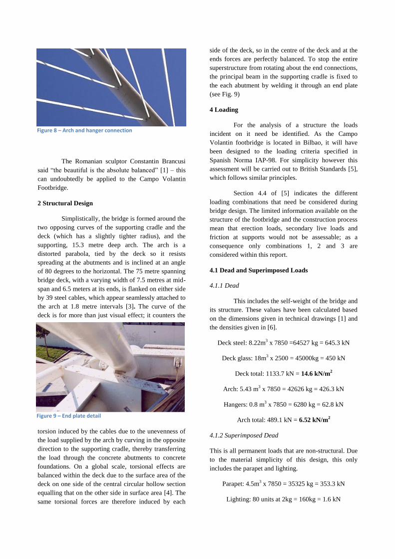
In such a conventional arch structure, the
forces would be taken from the arch directly through a
solid embankment and into the ground. In Bilbao
however, the bridge is supported on pre-cast concrete
cantilevered sections rising up from the river bank,
replacing the solidity of a typical solid embankment
with an empty space. This creates an interesting effect,
the void complimenting the openness of the bridge
structure and adds to the directionality expressed by the
arch and deck, dictated by the flow of the river.
Furthermore, the sculptural, half arch cantilevered
supports are well refined and structurally efficient,
tapering towards their end whilst resisting a
diminishing Bending Moment.
Calatrava has always placed a particular
emphasis on stairways (see Fig. 6). Attention is taken
away for the stairways purpose and focus is given to
them providing a sense of continuity and synchronicity
between the bridge and the ground. The solid/void
balance is enhanced by the lightness of the structure,
achieved primarily by the glass decking. The
translucent deck shows the bare bones of the
supporting structure making it clear how the load is
carried and enhancing the shallow deck, which like the
rest of the structure appears to be very delicate and as
such very expressive.
The entire structure has an obvious connection
with nature, the basic composition of steel and glass
representing a skeletal framework (see Fig. 7). The
panels of translucent glass are supported by narrow
stainless steel ribs resembling the back bone of a fish; a
nice effect for a structure which spans a river,
especially considering the reflection in the water. This
is particularly effective due to the bridges lighting, as
the white structure is and translucent deck are
illuminated. This accentuates the symbolic appeal of
the bridge making it a beacon within the area.
The complexity of the curves in the structure
give the Campo Volantin a stronger presence than
other bridges of such a span, something which is useful
due to the structures proximity to Frank Gehry‟s
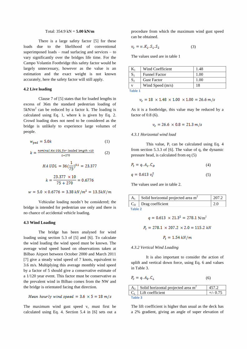
Guggenheim. All connections appear to be minimally
elegant, especially the cables which connect simply
and seamlessly with the arch and perimeter circular
hollow sections (see Fig 8).
Figure 5 – Void beneath the support
Figure 6 – stairway and ramp
Figure 7 – Skeletal framework of the bridge soffit
The Romanian sculptor Constantin Brancusi
said “the beautiful is the absolute balanced” [1] – this
can undoubtedly be applied to the Campo Volantin
Footbridge.
2 Structural Design
Simplistically, the bridge is formed around the
two opposing curves of the supporting cradle and the
deck (which has a slightly tighter radius), and the
supporting, 15.3 metre deep arch. The arch is a
distorted parabola, tied by the deck so it resists
spreading at the abutments and is inclined at an angle
of 80 degrees to the horizontal. The 75 metre spanning
bridge deck, with a varying width of 7.5 metres at mid-
span and 6.5 meters at its ends, is flanked on either side
by 39 steel cables, which appear seamlessly attached to
the arch at 1.8 metre intervals [3]. The curve of the
deck is for more than just visual effect; it counters the
torsion induced by the cables due to the unevenness of
the load supplied by the arch by curving in the opposite
direction to the supporting cradle, thereby transferring
the load through the concrete abutments to concrete
foundations. On a global scale, torsional effects are
balanced within the deck due to the surface area of the
deck on one side of the central circular hollow section
equalling that on the other side in surface area [4]. The
same torsional forces are therefore induced by each
side of the deck, so in the centre of the deck and at the
ends forces are perfectly balanced. To stop the entire
superstructure from rotating about the end connections,
the principal beam in the supporting cradle is fixed to
the each abutment by welding it through an end plate
(see Fig. 9)
4 Loading
For the analysis of a structure the loads
incident on it need be identified. As the Campo
Volantin footbridge is located in Bilbao, it will have
been designed to the loading criteria specified in
Spanish Norma IAP-98. For simplicity however this
assessment will be carried out to British Standards [5],
which follows similar principles.
Section 4.4 of [5] indicates the different
loading combinations that need be considered during
bridge design. The limited information available on the
structure of the footbridge and the construction process
mean that erection loads, secondary live loads and
friction at supports would not be assessable; as a
consequence only combinations 1, 2 and 3 are
considered within this report.
4.1 Dead and Superimposed Loads
4.1.1 Dead
This includes the self-weight of the bridge and
its structure. These values have been calculated based
on the dimensions given in technical drawings [1] and
the densities given in [6].
Deck steel: 8.22m3 x 7850 =64527 kg = 645.3 kN
Deck glass: 18m3 x 2500 = 45000kg = 450 kN
Deck total: 1133.7 kN = 14.6 kN/m2
Arch: 5.43 m3 x 7850 = 42626 kg = 426.3 kN
Hangers: 0.8 m3 x 7850 = 6280 kg = 62.8 kN
Arch total: 489.1 kN = 6.52 kN/m2
4.1.2 Superimposed Dead
This is all permanent loads that are non-structural. Due
to the material simplicity of this design, this only
includes the parapet and lighting.
Parapet: 4.5m3 x 7850 = 35325 kg = 353.3 kN
Lighting: 80 units at 2kg = 160kg = 1.6 kN
Figure 8 – Arch and hanger connection
Figure 9 – End plate detail
Total: 354.9 kN = 5.00 kN/m
There is a large safety factor [5] for these
loads due to the likelihood of conventional
superimposed loads – road surfacing and services – to
vary significantly over the bridges life time. For the
Campo Volantin Footbridge this safety factor would be
largely unnecessary, however as the value is an
estimation and the exact weight is not known
accurately, here the safety factor will still apply.
4.2 Live loading
Clause 7 of [5] states that for loaded lengths in
excess of 36m the standard pedestrian loading of
5kN/m2 can be reduced by a factor k. The loading is
calculated using Eq. 1, where k is given by Eq. 2.
Crowd loading does not need to be considered as the
bridge is unlikely to experience large volumes of
people.
(1)
(2)
Vehicular loading needn‟t be considered; the
bridge is intended for pedestrian use only and there is
no chance of accidental vehicle loading.
4.3 Wind Loading
The bridge has been analysed for wind
loading using section 5.3 of [5] and [6]. To calculate
the wind loading the wind speed must be known. The
average wind speed based on observations taken at
Bilbao Airport between October 2000 and March 2011
[7] give a steady wind speed of 7 knots, equivalent to
3.6 m/s. Multiplying this average monthly wind speed
by a factor of 5 should give a conservative estimate of
a 1/120 year event. This factor must be conservative as
the prevalent wind in Bilbao comes from the NW and
the bridge is orientated facing that direction.
The maximum wind gust speed vc must first be
calculated using Eq. 4. Section 5.4 in [6] sets out a
procedure from which the maximum wind gust speed
can be obtained.
(3)
The values used are in table 1
As it is a footbridge, this value may be reduced by a
factor of 0.8 (6).
4.3.1 Horizontal wind load
This value, Pt can be calculated using Eq. 4
from section 5.3.3 of [6]. The value of q, the dynamic
pressure head, is calculated from eq (5)
(4)
(5)
The values used are in table 2.
N/m2
4.3.2 Vertical Wind Loading
It is also important to consider the action of
uplift and vertical down force, using Eq. 6 and values
in Table 3.
(6)
A3 Solid horizontal projected area m2 457.2
CL Lift coefficient +/- 0.75
Table 3
The lift coefficient is higher than usual as the deck has
a 2% gradient, giving an angle of super elevation of
Table 1
Table 2
K1 Wind Coefficient 1.48
S1 Funnel Factor 1.00
S2 Gust Factor 1.00
v Wind Speed (m/s) 18
A1 Solid horizontal projected area m2
207.2
CD Drag coefficient 2.0
1.14⁰. As this value is > 1 a higher coefficient is used
[5].
N/m2
4.3.3 Longitudinal Wind Load
This is the sum of the nominal longitudinal
wind load on the bridge PLS and the nominal
longitudinal wind load on the live load, PLL. It is
calculated using Eq. 7.
(7)
(8)
(9)
The values used are in table 4.
4.3.4 Wind Loading Combination
The wind loads PT, PL and PV shall be
considered in four separate combination cases, as
specified in clause 5.3.6 of [5] and shown in table 5.
Table 5
It is evident that combination b) is dominant. The un-
factored wind loading is therefore 210.5 kN or 2.81
kN/m
4.4 Temperature Loading
A change in the temperature of an object can
induce strains, and as a consequence stresses within an
object. There are two ways in which temperature
differences can cause stress within a bridge, as
specified in section 5.4 of [5]. These are:
Changes in the overall effective temperature
of the bridge superstructure
Differences in temperature between the top
and bottom surfaces.
There is the potential for large temperature variations
in Spain. As the arch is tied by the deck, there is
restraint of associated expansion or contraction, known
as temperature restraint [5]. This can cause large
stresses within the superstructure.
4.4.1 Effective Temperature
Footbridges are designed to a 50 year design
period so are subject to reduced maximum and
minimum temperature. However, temperature
information is only available for the past two decades,
so this paper will take these values as they are. The
highest temperature was experienced in August (46 C)
and the lowest in February (-8). From tables 10 and 11
in chapter 5.4 of [5], assuming the bridge behaves
similarly to those in group two, the assumed and
effective temperatures can be derived and are shown in
table 6.
Table 6
As the bridge opened in May 1997, this paper assumes
the bridge was placed on its supports in Spring, at a
temperature of 18⁰C.
The maximum temperature change is therefore +30 C
or -27 C. Taking α = 12 x 10-6
, Eq. 10 gives strain, ε.
(10)
This gives a strain of +360 με or -324 με leading to the
extensions below.
Deck, length 75m = +27.0mm/-24.3mm
Cables, max length 15m = +5.4 mm/ -4.9 mm
A1 Solid horizontal projected area m2 3.04
CD Drag coefficient 2.0
A1.1 Projected area of live load m2 5.0
Table 4
Case Combination Value
a) Pt alone 115.2 kN
b) Pt +/- Pv 210.5 kN
c) PL alone 1.81 kN
d) 0.5Pt + PL +/- 0.5 PV 107.1 kN
Assumed Air Shade
Temperature
Effective Bridge
Temperature
Minimum -8 Minimum -9
Maximum + 38 Maximum + 48
The maximum deck extension is therefore
0.027m and easily accommodated for with an
expansion joint. If expansion or contraction is
restricted:
(11)
The deck restraining the arch during its
expansion will increase the tension within the cables as
it tried to expand outwards, increasing the stress within
the deck where the cables are attached.
4.4.2 Temperature Differences Across the Deck
As the structure is so light, the deck so
shallow and decking translucent there is unlikely to be
a temperature difference between the top and the
bottom of the deck..
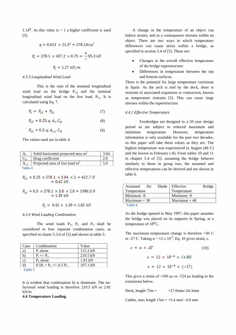
4.5 Natural Frequency
It is important to design footbridges which
don‟t vibrate excessively. The Natural Frequency
should lie within the range of 5Hz < fo< 75Hz [5].
(12)
The deck is simplified to that in Figure 2 so that I is
taken as Eq. 13.
(13)
The mode of vibration is based on a fixed-fixed beam;
(βnl)2 = 22.37 (5).
This value is just acceptable.
4.6 Design Loads
Having assessed the nominal loads experienced by the
bridge, final design loads can be calculated by applying
a safety factor of which there are two types. These are
the partial load factor γfl and the inaccuracy factor γf3.
The partial load factor varies depending on which load
is being considered and are specified in table 7. The
inaccuracy factor allows for errors in analysis. γf3 =
1.00 at SLS and γf3 = 1.10 at ULS for steel bridges and
have been factored during calculation in this paper.
Table 8 shows the final design loading
4.6.1 Combinations
Combination 1
The permanent loads and primary live loads
(14)
Table 7
Comb.
1
Comb.
2
Comb.
3
Dead ULS
SLS
1.05
1.00
1.05
1.00
1.05
1.00
Superimposed
Dead
ULS
SLS
1.2
1.0
1.2
1.0
1.2
1.0
Wind ULS
SLS
-
-
1.1
1.0
-
-
Temperature ULS
SLS
-
-
-
-
1.3
1.0
Pedestrian and
cycle
ULS
SLS
1.5
1.1
1.25
1.0
1.25
1.0
LOAD Component ULS
(kN/m)
SLS
(kN/m)
Dead Deck
Arch
Total
15.3
6.85
23.2
14.6
6.52
21.1
Superimposed
Dead
Total
6.00
5.00
Pedestrian and
Cycle
20.3
16.9
14.9
13.5
Wind Vertical +
Horizontal (b)
3.1
2.81
Temperature Expansion
restraint
5.12
3.94
Table 8
7m
0.84m
Figure 10
Combination 2
The loads from combination 1 plus wind loads
(15)
Combination 3
The loads from combination 1 plus temperature loads
(16)
Combinations 4 and 5 have not been considered within
this paper.
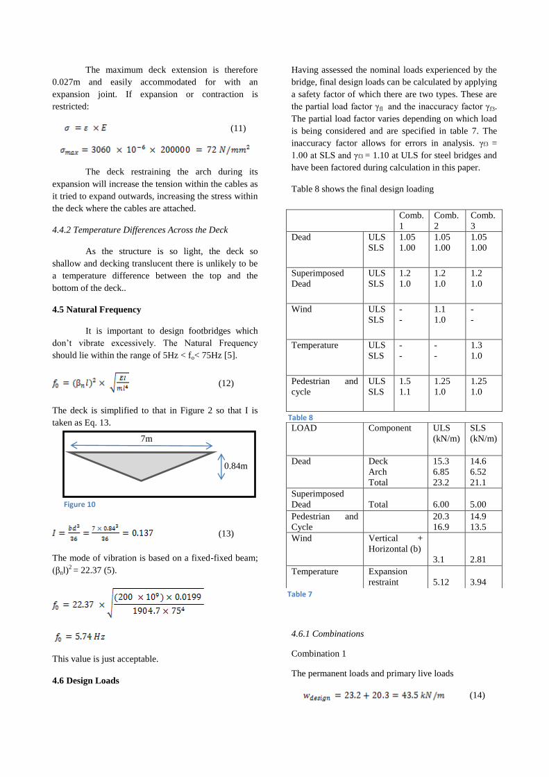
5 Structural Analyses
5.1 Bending moment in Arch
The ULS design loads from combination 1 in Eq. 14
have been used to calculate the maximum bending
moment, with the live loads applied to one half of the
arch shown in (see Fig 11).
Figure 3 can be modelled as a simply supported beam,
assuming the arch redistributes the load and the dead
load causes no moment – Figure 12.
The maximum moment can be calculated from Eq. 17
(8).
(17)
The stress in the arch is found by using Eq. 18.
(18)
The factored design strength is likely to be 365 N/mm2
so this stress is acceptable.
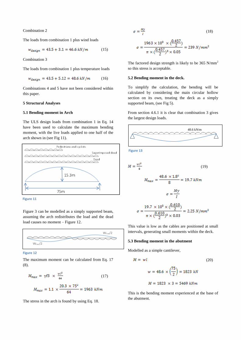
5.2 Bending moment in the deck.
To simplify the calculation, the bending will be
calculated by considering the main circular hollow
section on its own, treating the deck as a simply
supported beam, (see Fig 5).
From section 4.6.1 it is clear that combination 3 gives
the largest design loads.
(19)
This value is low as the cables are positioned at small
intervals, generating small moments within the deck.
5.3 Bending moment in the abutment
Modelled as a simple cantilever,
(20)
This is the bending moment experienced at the base of
the abutment.
Figure 11
Figure 12
48.6 kN/m
Figure 13
5.4 Cables
Under the assumption that the cables transfer all live
load and the dead weight of the deck, parapets and
lighting to the arch, the axial force in the cables can be
calculated. This also takes into account stress induced
by temperature change.
From diagrams it has been assumed the cables are
separated at equal intervals of 1.8m [1].
(21)
This is well below the design strength of steel.
6 Construction
Tied arches, due to the horizontal thrust being
contained within the structure by the deck can be
prefabricated off site and then lifted into position. This
is advantageous as some erection loading conditions,
which often result in the most adverse combinations,
needn‟t be considered. Information regarding the
construction of the Campo Volantin footbridge is
limited; this paper considers potential likely
construction methods based on similar steel bridges,
such as the York Millennium Bridge [9].
The sections of the bridge components; cradle
structure, arch, structural glass decking and cables will
have been delivered to site individually. Temporary
frame work will have supported the arch and deck,
which were erected in pre-set positions within the
frame. The arch and central circular hollow section
would then have been welded together (see Fig. 1) and
the arch released to take its shape.
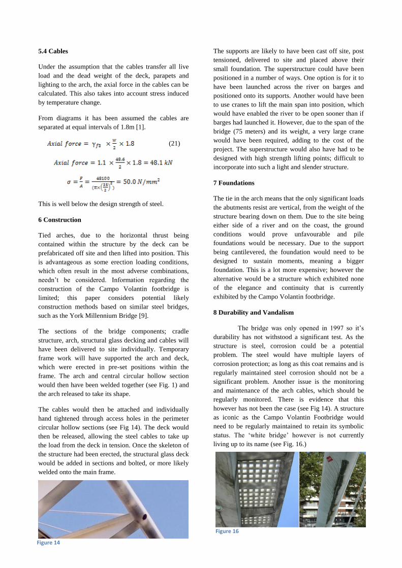
The cables would then be attached and individually
hand tightened through access holes in the perimeter
circular hollow sections (see Fig 14). The deck would
then be released, allowing the steel cables to take up
the load from the deck in tension. Once the skeleton of
the structure had been erected, the structural glass deck
would be added in sections and bolted, or more likely
welded onto the main frame.
The supports are likely to have been cast off site, post
tensioned, delivered to site and placed above their
small foundation. The superstructure could have been
positioned in a number of ways. One option is for it to
have been launched across the river on barges and
positioned onto its supports. Another would have been
to use cranes to lift the main span into position, which
would have enabled the river to be open sooner than if
barges had launched it. However, due to the span of the
bridge (75 meters) and its weight, a very large crane
would have been required, adding to the cost of the
project. The superstructure would also have had to be
designed with high strength lifting points; difficult to
incorporate into such a light and slender structure.
7 Foundations
The tie in the arch means that the only significant loads
the abutments resist are vertical, from the weight of the
structure bearing down on them. Due to the site being
either side of a river and on the coast, the ground
conditions would prove unfavourable and pile
foundations would be necessary. Due to the support
being cantilevered, the foundation would need to be
designed to sustain moments, meaning a bigger
foundation. This is a lot more expensive; however the
alternative would be a structure which exhibited none
of the elegance and continuity that is currently
exhibited by the Campo Volantin footbridge.
8 Durability and Vandalism
The bridge was only opened in 1997 so it‟s
durability has not withstood a significant test. As the
structure is steel, corrosion could be a potential
problem. The steel would have multiple layers of
corrosion protection; as long as this coat remains and is
regularly maintained steel corrosion should not be a
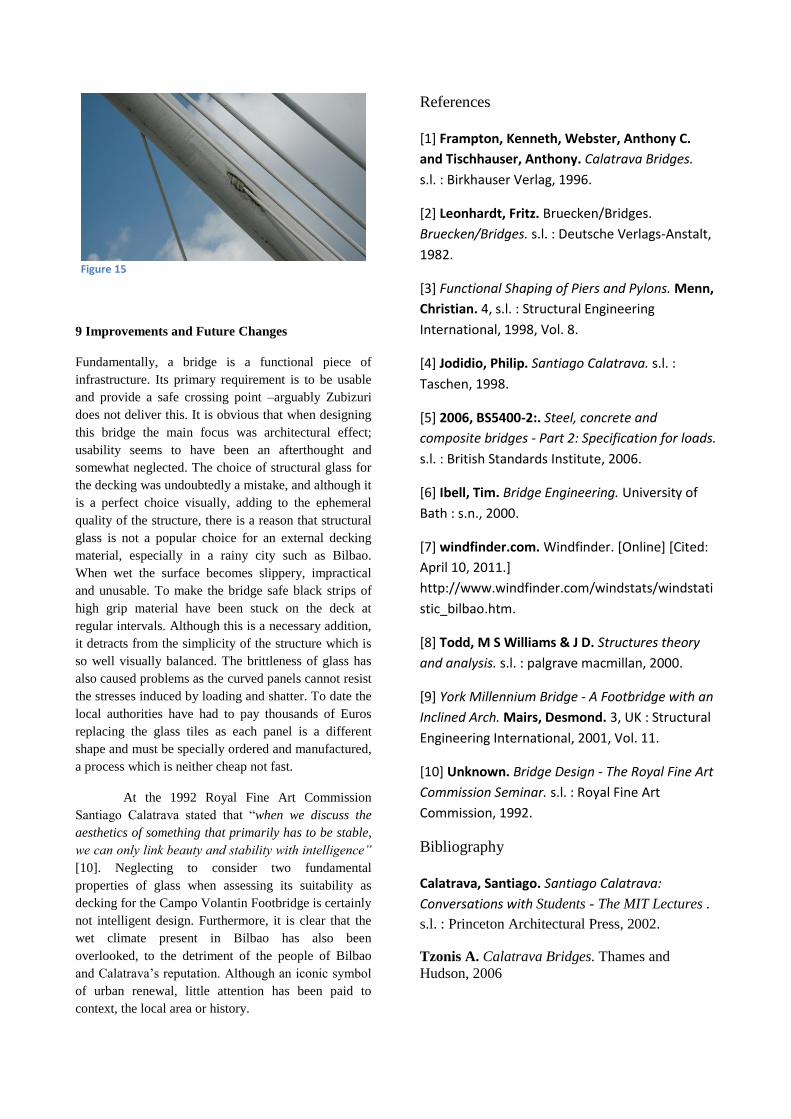
significant problem. Another issue is the monitoring
and maintenance of the arch cables, which should be
regularly monitored. There is evidence that this
however has not been the case (see Fig 14). A structure
as iconic as the Campo Volantin Footbridge would
need to be regularly maintained to retain its symbolic
status. The „white bridge‟ however is not currently
living up to its name (see Fig. 16.)
Figure 16
Figure 14
9 Improvements and Future Changes
Fundamentally, a bridge is a functional piece of
infrastructure. Its primary requirement is to be usable
and provide a safe crossing point –arguably Zubizuri
does not deliver this. It is obvious that when designing
this bridge the main focus was architectural effect;
usability seems to have been an afterthought and
somewhat neglected. The choice of structural glass for
the decking was undoubtedly a mistake, and although it
is a perfect choice visually, adding to the ephemeral
quality of the structure, there is a reason that structural
glass is not a popular choice for an external decking
material, especially in a rainy city such as Bilbao.
When wet the surface becomes slippery, impractical
and unusable. To make the bridge safe black strips of
high grip material have been stuck on the deck at
regular intervals. Although this is a necessary addition,
it detracts from the simplicity of the structure which is
so well visually balanced. The brittleness of glass has
also caused problems as the curved panels cannot resist
the stresses induced by loading and shatter. To date the
local authorities have had to pay thousands of Euros
replacing the glass tiles as each panel is a different
shape and must be specially ordered and manufactured,
a process which is neither cheap not fast.
At the 1992 Royal Fine Art Commission
Santiago Calatrava stated that “when we discuss the
aesthetics of something that primarily has to be stable,
we can only link beauty and stability with intelligence”
[10]. Neglecting to consider two fundamental
properties of glass when assessing its suitability as
decking for the Campo Volantin Footbridge is certainly
not intelligent design. Furthermore, it is clear that the
wet climate present in Bilbao has also been
overlooked, to the detriment of the people of Bilbao
and Calatrava‟s reputation. Although an iconic symbol
of urban renewal, little attention has been paid to
context, the local area or history.
References
[1] Frampton, Kenneth, Webster, Anthony C.
and Tischhauser, Anthony. Calatrava Bridges.
s.l. : Birkhauser Verlag, 1996.
[2] Leonhardt, Fritz. Bruecken/Bridges.
Bruecken/Bridges. s.l. : Deutsche Verlags-Anstalt,
1982.
[3] Functional Shaping of Piers and Pylons. Menn,
Christian. 4, s.l. : Structural Engineering
International, 1998, Vol. 8.
[4] Jodidio, Philip. Santiago Calatrava. s.l. :
Taschen, 1998.
[5] 2006, BS5400-2:. Steel, concrete and
composite bridges - Part 2: Specification for loads.
s.l. : British Standards Institute, 2006.
[6] Ibell, Tim. Bridge Engineering. University of
Bath : s.n., 2000.
[7] windfinder.com. Windfinder. [Online] [Cited:
April 10, 2011.]
http://www.windfinder.com/windstats/windstati
stic_bilbao.htm.
[8] Todd, M S Williams & J D. Structures theory
and analysis. s.l. : palgrave macmillan, 2000.
[9] York Millennium Bridge - A Footbridge with an
Inclined Arch. Mairs, Desmond. 3, UK : Structural
Engineering International, 2001, Vol. 11.
[10] Unknown. Bridge Design - The Royal Fine Art
Commission Seminar. s.l. : Royal Fine Art
Commission, 1992.
Bibliography
Calatrava, Santiago. Santiago Calatrava:
Conversations with Students - The MIT Lectures .
s.l. : Princeton Architectural Press, 2002.
Tzonis A. Calatrava Bridges. Thames and
Hudson, 2006
Figure 15