Embed Size (px)
Citation preview
IEEE
In
du
str
y A
pp
lIc
AtI
on
s M
Ag
AzI
nE
• s
Ept|
oc
t 20
13 •
ww
w.I
EEE.
or
g/I
As
14
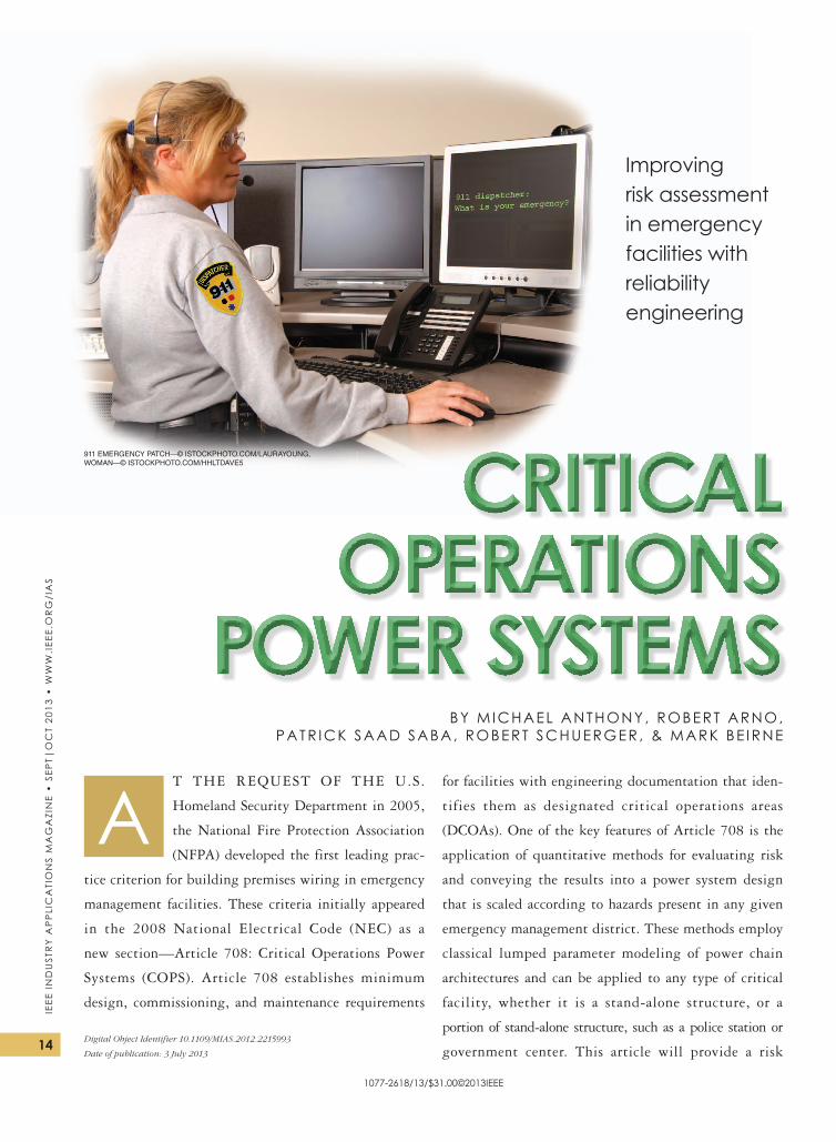
t the request of the u.s.
homeland security Department in 2005,
the National fire Protection Association
(NfPA) developed the first leading prac-
tice criterion for building premises wiring in emergency
management facilities. these criteria initially appeared
in the 2008 National electrical Code (NeC) as a
new section—Article 708: Critical operations Power
systems (CoPs). Article 708 establishes minimum
design, commissioning, and maintenance requirements
for facilities with engineering documentation that iden-
tifies them as designated critical operations areas
(DCoAs). one of the key features of Article 708 is the
application of quantitative methods for evaluating risk
and conveying the results into a power system design
that is scaled according to hazards present in any given
emergency management district. these methods employ
classical lumped parameter modeling of power chain
architectures and can be applied to any type of critical
facility, whether it is a stand-alone structure, or a
portion of stand-alone structure, such as a police station or
government center. this article will provide a risk
1077-2618/13/$31.00©2013IEEE
Digital Object Identifier 10.1109/MIAS.2012.2215993
Date of publication: 3 July 2013
A
CritiCal OperatiOns
pOwer systemsBY MICHAEL ANTHONY, ROBERT ARNO,
PATR ICK SAAD SABA, ROBERT SCHUERGER, & MARK BE IRNE
Improving risk assessment in emergency facilities with reliability engineering
911 emergency patch—© istockphoto.com/laurayoung, woman—© istockphoto.com/hhltdave5
15
IEEE Ind
ustr
y A
pp
lIcA
tIon
s MA
gA
zInE •
sEpt|
oc
t 2013 • w
ww
.IEEE.or
g/IA
s
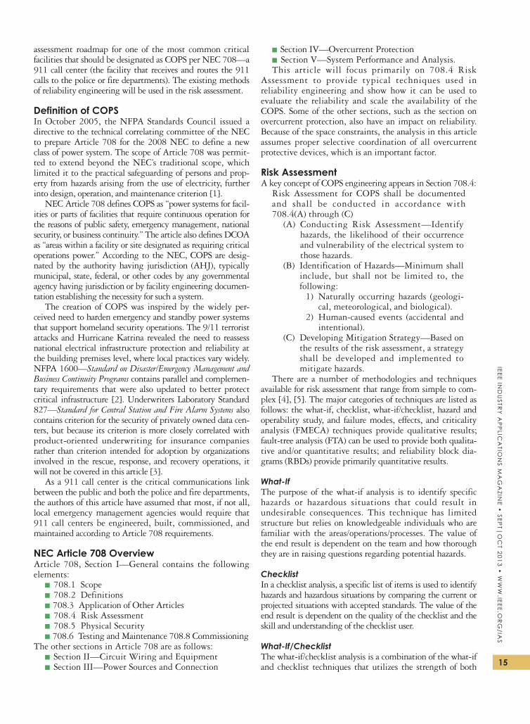
assessment roadmap for one of the most common critical facilities that should be designated as CoPs per NeC 708—a 911 call center (the facility that receives and routes the 911 calls to the police or fire departments). the existing methods of reliability engineering will be used in the risk assessment.
Definition of COPS In october 2005, the NfPA standards Council issued a directive to the technical correlating committee of the NeC to prepare Article 708 for the 2008 NeC to define a new class of power system. the scope of Article 708 was permit-ted to extend beyond the NeC’s traditional scope, which limited it to the practical safeguarding of persons and prop-erty from hazards arising from the use of electricity, further into design, operation, and maintenance criterion [1].
NeC Article 708 defines CoPs as “power systems for facil-ities or parts of facilities that require continuous operation for the reasons of public safety, emergency management, national security, or business continuity.” the article also defines DCoA as “areas within a facility or site designated as requiring critical operations power.” According to the NeC, CoPs are desig-nated by the authority having jurisdiction (AhJ), typically municipal, state, federal, or other codes by any governmental agency having jurisdiction or by facility engineering documen-tation establishing the necessity for such a system.
the creation of CoPs was inspired by the widely per-ceived need to harden emergency and standby power systems that support homeland security operations. the 9/11 terrorist attacks and hurricane Katrina revealed the need to reassess national electrical infrastructure protection and reliability at the building premises level, where local practices vary widely. NfPA 1600—Standard on Disaster/Emergency Management and Business Continuity Programs contains parallel and complemen-tary requirements that were also updated to better protect critical infrastructure [2]. underwriters Laboratory standard 827—Standard for Central Station and Fire Alarm Systems also contains criterion for the security of privately owned data cen-ters, but because its criterion is more closely correlated with product-oriented underwriting for insurance companies rather than criterion intended for adoption by organizations involved in the rescue, response, and recovery operations, it will not be covered in this article [3].
As a 911 call center is the critical communications link between the public and both the police and fire departments, the authors of this article have assumed that most, if not all, local emergency management agencies would require that 911 call centers be engineered, built, commissioned, and maintained according to Article 708 requirements.
NEC Article 708 OverviewArticle 708, section I—General contains the following elements:
▪ 708.1 scope
▪ 708.2 Definitions
▪ 708.3 Application of other Articles
▪ 708.4 risk Assessment
▪ 708.5 Physical security
▪ 708.6 testing and Maintenance 708.8 Commissioningthe other sections in Article 708 are as follows:
▪ section II— Circuit Wiring and equipment
▪ section III— Power sources and Connection
▪ section IV—overcurrent Protection
▪ section V—system Performance and Analysis.this article will focus primarily on 708.4 risk
Assessment to provide typical techniques used in reliability engineering and show how it can be used to evaluate the reliability and scale the availability of the CoPs. some of the other sections, such as the section on overcurrent protection, also have an impact on reliability. Because of the space constraints, the analysis in this article assumes proper selective coordination of all overcurrent protective devices, which is an important factor.
Risk AssessmentA key concept of CoPs engineering appears in section 708.4:
risk Assessment for CoPs shall be documented and shall be conducted in accordance with 708.4(A) through (C)
(A) Conducting risk Assessment—Identify hazards, the likelihood of their occurrence and vulnerability of the electrical system to those hazards.
(B) Identification of hazards—Minimum shall include, but shall not be limited to, the following:
1) Naturally occurring hazards (geologi-cal, meteorological, and biological).
2) human-caused events (accidental and intentional).
(C) Developing Mitigation strategy—Based on the results of the risk assessment, a strategy shall be developed and implemented to mitigate hazards.
there are a number of methodologies and techniques available for risk assessment that range from simple to com-plex [4], [5]. the major categories of techniques are listed as follows: the what-if, checklist, what-if/checklist, hazard and operability study, and failure modes, effects, and criticality analysis (fMeCA) techniques provide qualitative results; fault-tree analysis (ftA) can be used to provide both qualita-tive and/or quantitative results; and reliability block dia-grams (rBDs) provide primarily quantitative results.
What-Ifthe purpose of the what-if analysis is to identify specific hazards or hazardous situations that could result in undesirable consequences. this technique has limited structure but relies on knowledgeable individuals who are familiar with the areas/operations/processes. the value of the end result is dependent on the team and how thorough they are in raising questions regarding potential hazards.
ChecklistIn a checklist analysis, a specific list of items is used to identify hazards and hazardous situations by comparing the current or projected situations with accepted standards. the value of the end result is dependent on the quality of the checklist and the skill and understanding of the checklist user.
What-If/Checklistthe what-if/checklist analysis is a combination of the what-if and checklist techniques that utilizes the strength of both
IEEE
In
du
str
y A
pp
lIc
AtI
on
s M
Ag
AzI
nE
• s
Ept|
oc
t 20
13 •
ww
w.I
EEE.
or
g/I
As
16
methods to complete the risk assessment. the what-if ques-tions are developed and the checklist(s) used to encourage the creativity of the what-if process as well as to fill in any gaps in the process of developing questions. the value of the final result is dependent on the team and how thorough they are in raising questions regarding potential hazards.
Hazard and Operability StudyA hazard and operability study requires an interdisciplinary team that is very knowledgeable about the areas/operations/processes to be assessed. this approach is thorough, time con-suming, and costly. the value of the final result depends on the skill and understanding of the team, the quality of the ref-erence material available, the ability of the team to function as a team, and the presence of strong, positive leadership.
Failure Modes, Effects, and Criticality AnalysisIn an fMeCA, each element in a system is examined both individually and collectively to determine the effect when one or more elements fail. this is a bottom-up approach: each of the elements is examined, all of the ways it can fail are listed (failure modes), and the effect of each failure to the element itself and on the overall system is predicted. then, a criticality level is assigned for each failure mode based on the overall effect on the system. An interdisciplinary team is required, and it is time consuming in direct proportion to how thorough and to what level of detail the analysis is conducted. this technique is useful for assessing potential equipment failures and how they impact the overall mission of the system being analyzed. the value of the final result is dependent on the skill and under-standing of the team and the scope of the analysis performed.
Fault-Tree Analysis ftA is a top-down approach in which an undesirable event is identified as the top event in the tree, with the potential causes that could lead to the undesirable event identified as branches below. Boolean algebra is used to connect the potential causes of failure in the branches to other branches and to the top event. If the failure rate (fr) and repair data are available for all of the initiating failures in the fault tree, quantitative results (unreliability and unavailability) can be calculated for the top event and each of the branches. the value of the assess-ment is dependent on the team’s competence in using the ftA process, skill and understanding of the systems it is analyzing, and the depth to which it conducts the analysis.
Reliability Block DiagramAn rBD is a block diagram in which the major components are connected together in the same manner as they are in a lumped parameter one-line or piping diagram. each of the blocks has the failure and repair data for that component included in the block. the junctions connecting the blocks are set according to the system redundancy (e.g., one out of two when there are two components and only one is required to carry the load). quantitative results (reliability, availabil-ity, and so forth) for the rBD are obtained by performing the series and parallel combinations of the blocks.
Risk Assessment of COPSrisk assessment for CoPs is performed to identify haz-ards, the likelihood of their occurrence, and the
vulnerability of the CoPs to those hazards. these hazards include equipment failure, inclement weather, flooding, earthquakes, and civil disturbances (see NfPA 1600 Appendix 5.3 for a more comprehensive list of potential vulnerability parameters). this assessment could be called a vulnerability analysis. from the vulnerability analysis, the power distribution architecture and supporting mechanical systems can then be properly selected to achieve the desired reliability [6].
It is noteworthy that the hazards listed in 708.4(B) are not just items that could cause the electrical system to fail. obviously, electrical systems are immune to biological hazards. NfPA 1600-2007—Standard on Disaster/Emergency Management and Business Continuity Programs can be used as a model for Article 708 and is referenced in many places. therefore, the risk assessment should be comprehensive and look at all of the major hazards that would take the 911 call center out of service.
for our example 911 call center, we use a very robust design in which there are two complete systems for each part of the critical infrastructure. In the data center world, this is referred to as 2N, in which N is the num-ber (needed). the critical systems are as follows:
1) electrical power (ac)2) electrical power (dc)3) mechanical cooling system4) telephone system5) shortwave radio system6) It systems including Internet connection7) building life safety systems (structural and fire pro-
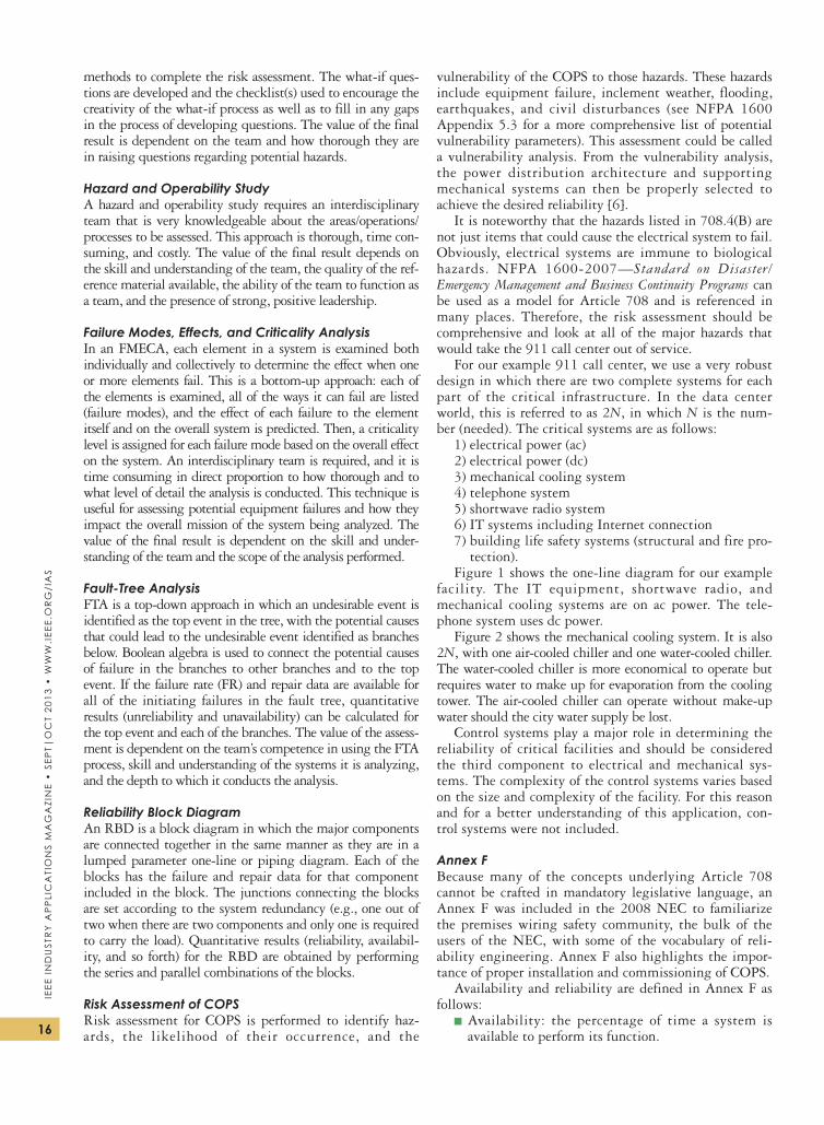
tection).figure 1 shows the one-line diagram for our example
facility. the It equipment, shortwave radio, and mechanical cooling systems are on ac power. the tele-phone system uses dc power.
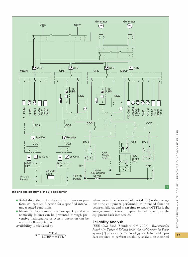
figure 2 shows the mechanical cooling system. It is also 2N, with one air-cooled chiller and one water-cooled chiller. the water-cooled chiller is more economical to operate but requires water to make up for evaporation from the cooling tower. the air-cooled chiller can operate without make-up water should the city water supply be lost.
Control systems play a major role in determining the reliability of critical facilities and should be considered the third component to electrical and mechanical sys-tems. the complexity of the control systems varies based on the size and complexity of the facility. for this reason and for a better understanding of this application, con-trol systems were not included.
Annex FBecause many of the concepts underlying Article 708 cannot be crafted in mandatory legislative language, an Annex f was included in the 2008 NeC to familiarize the premises wiring safety community, the bulk of the users of the NeC, with some of the vocabulary of reli-ability engineering. Annex f also highlights the impor-tance of proper installation and commissioning of CoPs.
Availability and reliability are defined in Annex f as follows:
▪ Availability: the percentage of time a system is available to perform its function.
17
IEEE Ind
ustr
y A
pp
lIcA
tIon
s MA
gA
zInE •
sEpt|
oc
t 2013 • w
ww
.IEEE.or
g/IA
s
▪ reliability: the probability that an item can per-form its intended function for a specified interval under stated conditions.
▪ Maintainability: a measure of how quickly and eco-nomically failures can be prevented through pre-ventive maintenance or system operation can be restored following failure.
Availability is calculated by
MTBF MTTRMTBFA =+
,
where mean time between failures (MtBf) is the average time the equipment performed its intended function between failures, and mean time to repair (Mttr) is the average time it takes to repair the failure and put the equipment back into service.
Reliability AnalysisIEEE Gold Book (standard 493-2007)—Recommended Practice for Design of Reliable Industrial and Commercial Power Systems [7] provides the methodology and failure and repair data required to perform reliability analysis on electrical
Utility
MECH
AC
Chi
ller
WC
Chi
ller
PC
WP
PC
WP
CW
P
AH
U 2
AH
U 1
CR
AC
Pan
el
Coo
ling
Tow
er
Hou
seP
anel
CR
AC
Pan
elH
ouse
Pan
el
MECHUPS
“N”UPS
SCC SCC
“N”UPS
UPSATS
RC1 RC2COD COD
DC1
48-V dcDP1
48-V dcLoad
48-V dcPanel1
48-V dcPanel2
48-V dcDP2
dc Conv dc Conv
Rectifier Rectifier
DC2 PDU PDU
RPP
STS
RPP
RPPSingleCord
PDUSingleCord
TypicalDual Corded
Server
ATS ATS ATS
UtilityGenerator Generator
1The one-line diagram of the 911 call center.
IEEE
In
du
str
y A
pp
lIc
AtI
on
s M
Ag
AzI
nE
• s
Ept|
oc
t 20
13 •
ww
w.I
EEE.
or
g/I
As
18
and mechanical systems. (space does not permit listing the actual data used.) the method used in the IEEE Gold Book is rBD. rBD is an effective method for analyzing systems with many interrelated items, such as an electrical distribu-tion system.
for simple systems that consist of series and parallel blocks, the calculations can be performed manually. for com-plex systems with standby components, such as the system shown in figure 1, reliability software is needed. table 1 shows the reliability analysis for figures 1 and 2, using reli-ability software to calculate the reliability, availability, MtBf, and Mttr for each.
there is a significant difference between what is consid-ered a failure for electrical power to the critical ac loads and dc telephone systems when compared to failure for power to the mechanical cooling systems. Momentary loss of power to the
critical ac loads and tele-phone systems is consid-ered a failure, as the uninterruptible power supply (uPs) system and the 48-V dc systems have batteries to provide power while the generators start (during loss of utility power). for the electrical power to the mechanical cooling systems, momen-tary loss of power is not considered a failure, as the mechanical cooling sys-tem is designed to go down and restart.
there is also a signifi-cant difference between loss of power to the criti-cal ac and dc loads and loss of cooling. Loss of power to the critical ac load or telephone system causes an immediate fail-ure. Loss of cooling does not. the equipment has to overheat before it shuts down, which may
take a significant amount of time.the reliability analysis shown for the mechanical
cooling system shows only the reliability of the equip-ment itself. It does not address the probability that any equipment will actually overheat.
the CoPs must operate for a long period of time, pro-viding power to systems that perform critical functions. section 708.22(C) specifically requires that the alternate power source is capable of operating 72 h at full load. therefore, the 911 call center would require significant onsite diesel fuel storage to be included in the design.
Additional Tools for the Risk AnalystAnnex f of NeC 2008 also provides direction on how to improve the availability of CoPs, both for existing and new facilities. the methodology includes the reliability
analysis of evaluating possible fail-ures of the system by conducting an fMeCA and/or an ftA. Because of the complexity of the modeling and interpretation of the risk analysis, Annex f refer-ences supporting documents.
the Army Corp of engineers Power reliability enhancement Program (PreP) training manual TM 5-698-4—FMECA for Com-mand, Control, Communications, Com-puter, Intelligence, Surveillance, and Reconnaissance (C4ISR) Facilities pro-vides the necessary information on the how to conduct an fMeCA [8].
CRAH-1 CRAH-3
Main Data CenterRedundancy: N + 1
AHU-1
CRAH-2 CRAH-4 AHU-2
CondenserWaterPumps
Water-Cooled Chiller
Air-Cooled Chiller
Variable FlowPrimary Pump
Variable FlowPrimary Pump
The cooling system for the 911 call center.2
TAblE 1. RElIAbIlITY ANAlYSIS FOR CRITICAl ElECTRICAl AND MECHANICAl SYSTEMS (FR = FAIlURES/H OF OPERATION).
Description of RBD FR MTTR (h) AvailabilityReliability (Five Years) (%)
Electrical power for critical ac loads
2.1464 E-06
6.31 0.9999865 7.70
Electrical power for critical dc loads
2.4037 E-06
5.92 0.9999858 9.03
Electrical power for mechanical system
5.4260 E-07
2.19 0.9999988 4.30
Mechanical cooling system
2.7977 E-07
7.15 0.9999980 1.46
19
IEEE Ind
ustr
y A
pp
lIcA
tIon
s MA
gA
zInE •
sEpt|
oc
t 2013 • w
ww
.IEEE.or
g/IA
s
As the name states, an fMeCA is the process of looking at all of the failure modes for the equipment or system being analyzed and determining what effect each failure would cause. there can be more than one effect, and it is normal to list them as primary, secondary, and so forth.
As a simple example, a molded case circuit breaker has the following major failure modes:
1) failure to open when it should2) failure to close when it should3) failure to conduct or stay closed when it should.the “when it should” part of each failure mode creates a
further breakdown of each. for example, the first (fail to open) might occur for a number of reasons, such as the following:
1) the thermal unit is defective and did not detect the overload.
2) the instantaneous (magnetic) element is defective and did not detect the short circuit.
3) the mechanism is defective and pulling the handle did not separate the contacts.
4) the contacts are welded shut from a previous failure and cannot be opened even manually.
Ieee standard 3007.2-2010—Recommended Practice for the Maintenance of Industrial and Commercial Power Systems also has a detailed example of an fMeA for a 480-V switchboard that demonstrates this process [9].
the fMeCA process is continued until all of the major failure modes for all of the equipment (or systems) being eval-uated have been listed out. then, the primary, secondary, and other effects are listed for each failure of each piece of equip-ment. In our example, assume that the circuit breaker was supplying a motor that pumped chilled water to the com-puter room air handling (CrAh) units. the primary effect of the circuit breaker not tripping could be that the motor keeps running and starts a fire (if it has a short circuit and the breaker upstream does not clear the fault), or the whole cool-ing system might pass down when the main breaker trips to clear the fault. the secondary effect may be the loss of some of the It equipment being cooled by the CrAh units, which in turn may create further effects. If the cooling system has been designed with redundancy, there may be no secondary effects, as loss of one pump might not cause any It equipment to overheat. If a fire starts, it might force the whole raised floor It load to go down regardless of the cooling system.
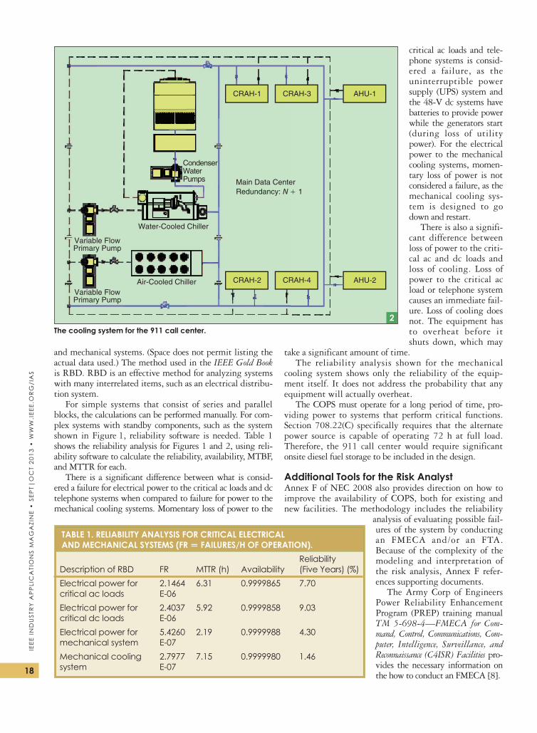
once all the failure modes and effects have been defined, the next step is to look at the criticality of the effects in conjunction with the probability of each one happening. the normal method is to have a gradient scale of criticality like the following example:
1) catastrophic: major human injury, significant finan-cial loss, and significant Pr impact
2) critical: significant loss of production and minor human injury
3) marginal: minor loss of production4) minor: no significant impact on productionthe probability of each failure is then addressed.
Another gradient scale is often used, such as the following:1) frequent2) reasonably probable3) occasional occurrence4) remote5) extremely unlikely.
each failure and its associated effect is then evaluated in terms of criticality and likelihood of occurrence and put into a matrix, as shown in figure 3.
If a system has been very well designed, no catastrophic events are likely to occur. often the point of doing the fMeCA in the first place is to evaluate how well the system has been designed. the fMeCA matrix points out which areas need to be addressed that will have the biggest impact on the overall operation of the system. It also shows which areas not to bother with, as either the hazards are extremely unlikely to occur or the effect when they do occur is minor.
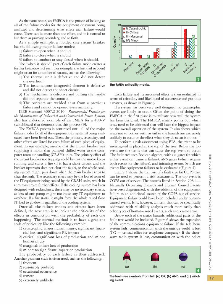
to perform a risk assessment using ftA, the event to be investigated is placed at the top of the tree. Below the top event are the items that can cause the top event to occur. the fault tree uses Boolean algebra, with or gates (in which either event can cause a failure), and gates (which require both events for the failure), and initiating events (which are events like equipment failures to be evaluated) (figure 4).
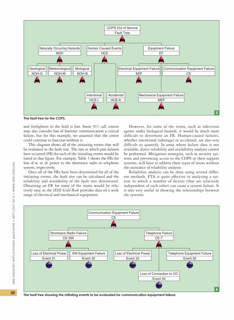
figure 5 shows the top part of a fault tree for CoPs that can be used to perform a risk assessment. the top event is CoPs out of service. the hazards listed in section 708.4—Naturally occurring hazards and human Caused events have been diagrammed, with the addition of the equipment failure as an additional source of the CoPs out of service. equipment failure could have been included under human-caused events. It is, however, an item that can be specifically addressed with reliability analysis much more easily than other types of human-caused events, such as operator error.
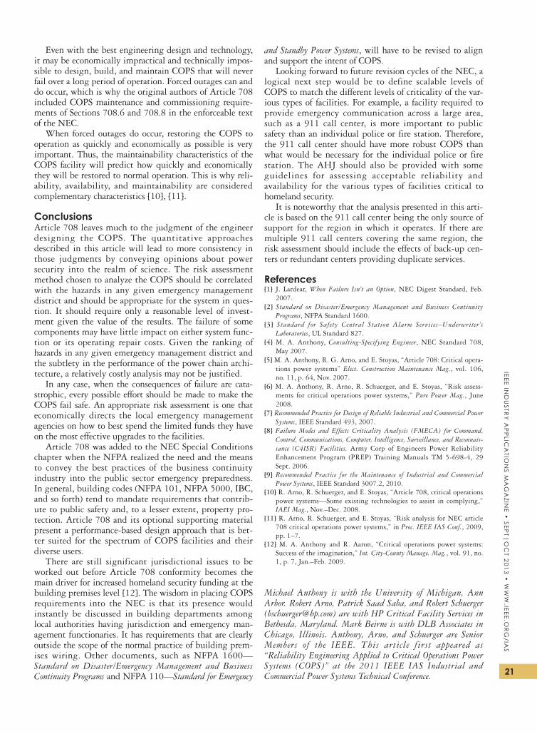
Below each of the major hazards, additional parts of the fault tree would be included. figure 6 shows the expansion of the communications equipment failure. If the telephone system fails, communication with the outside world is lost (Co = central office for telephone company). If the short-wave radio system is lost, communication with the police
0
2
4
6
8
10
A
Frequ
ent
C
Occas
ional
Occur
renc
e E
Extrem
ely
Unlike
lyB
Reaso
nably
Proba
bleD
Remot
e
Qua
ntity
I) CatastrophicII) CriticalIII) MarginalIV) Minor
The FMEA criticality matrix. 3
(a) (b) (c)
The fault-tree symbols: From left: (a) OR, (b) AND, and (c) initiat-ing event.
4
IEEE
In
du
str
y A
pp
lIc
AtI
on
s M
Ag
AzI
nE
• s
Ept|
oc
t 20
13 •
ww
w.I
EEE.
or
g/I
As
20
and firefighters in the field is lost. some 911 call centers may also consider loss of Internet communication a critical failure, but for this example, we assumed that the center could continue to function without it.
this diagram shows all of the initiating events that will be evaluated in the fault tree. the rate at which past failures have occurred (fr) for each of the initialing events would be listed in that figure. for example, table 1 shows the frs for loss of ac or dc power to the shortwave radio or telephone system, respectively.
once all of the frs have been determined for all of the initiating events, the fault tree can be calculated and the reliability and availability of the fault tree determined. obtaining an fr for some of the items would be rela-tively easy, as the IEEE Gold Book provides data on a wide range of electrical and mechanical equipment.
however, for some of the items, such as infectious agents under biological hazards, it would be much more difficult to determine an fr. human-caused failures, whether intentional (sabotage) or accidental, are also very difficult to quantify. In areas where failure data is not available, direct reliability and availability analysis cannot be performed. Mitigation strategies, such as security sys-tems and preventing access to the CoPs or their support systems, will have to address these types of issues without the assistance of reliability analysis.
reliability analysis can be done using several differ-ent methods. ftA is quite effective in analyzing a sys-tem in which a number of factors (that are relatively independent of each other) can cause a system failure. It is also very useful in showing the relationships between the systems.
COPS Out of Service
Fault Tree
Human Caused Events
HCE
Equipment Failure
EF
Naturally Occuring Hazards
NOH
Mechanical Equipment Failure
MEF
Electrical Equipment Failure
EEF
Communication Equipment Failure
CE
Intentional
HCE-I
Geological
NOH-G
Biological
NOH-B
Meteorological
NOH-M
Accidental
HCE-A
The fault tree for the COPS.5
Communication Equipment Failure
CE
Shortwave Radio Failure
CE-SW
Telephone Failure
CE-T
Telephone Equipment Failure
Event 35
Loss of Electrical Power
Event 33
Loss of Electrical Power
Event 31
SW Equipment Failure
Event 32
Loss of Connection to CO
Event 34
6The fault tree showing the initiating events to be evaluated for communication equipment failure.
21
IEEE Ind
ustr
y A
pp
lIcA
tIon
s MA
gA
zInE •
sEpt|
oc
t 2013 • w
ww
.IEEE.or
g/IA
s
even with the best engineering design and technology, it may be economically impractical and technically impos-sible to design, build, and maintain CoPs that will never fail over a long period of operation. forced outages can and do occur, which is why the original authors of Article 708 included CoPs maintenance and commissioning require-ments of sections 708.6 and 708.8 in the enforceable text of the NeC.
When forced outages do occur, restoring the CoPs to operation as quickly and economically as possible is very important. thus, the maintainability characteristics of the CoPs facility will predict how quickly and economically they will be restored to normal operation. this is why reli-ability, availability, and maintainability are considered complementary characteristics [10], [11].
ConclusionsArticle 708 leaves much to the judgment of the engineer designing the CoPs. the quantitative approaches described in this article will lead to more consistency in those judgments by conveying opinions about power security into the realm of science. the risk assessment method chosen to analyze the CoPs should be correlated with the hazards in any given emergency management district and should be appropriate for the system in ques-tion. It should require only a reasonable level of invest-ment given the value of the results. the failure of some components may have little impact on either system func-tion or its operating repair costs. Given the ranking of hazards in any given emergency management district and the subtlety in the performance of the power chain archi-tecture, a relatively costly analysis may not be justified.
In any case, when the consequences of failure are cata-strophic, every possible effort should be made to make the CoPs fail safe. An appropriate risk assessment is one that economically directs the local emergency management agencies on how to best spend the limited funds they have on the most effective upgrades to the facilities.
Article 708 was added to the NeC special Conditions chapter when the NfPA realized the need and the means to convey the best practices of the business continuity industry into the public sector emergency preparedness. In general, building codes (NfPA 101, NfPA 5000, IBC, and so forth) tend to mandate requirements that contrib-ute to public safety and, to a lesser extent, property pro-tection. Article 708 and its optional supporting material present a performance-based design approach that is bet-ter suited for the spectrum of CoPs facilities and their diverse users.
there are still significant jurisdictional issues to be worked out before Article 708 conformity becomes the main driver for increased homeland security funding at the building premises level [12]. the wisdom in placing CoPs requirements into the NeC is that its presence would instantly be discussed in building departments among local authorities having jurisdiction and emergency man-agement functionaries. It has requirements that are clearly outside the scope of the normal practice of building prem-ises wiring. other documents, such as NfPA 1600—Standard on Disaster/Emergency Management and Business Continuity Programs and NfPA 110—Standard for Emergency
and Standby Power Systems, will have to be revised to align and support the intent of CoPs.
Looking forward to future revision cycles of the NeC, a logical next step would be to define scalable levels of CoPs to match the different levels of criticality of the var-ious types of facilities. for example, a facility required to provide emergency communication across a large area, such as a 911 call center, is more important to public safety than an individual police or fire station. therefore, the 911 call center should have more robust CoPs than what would be necessary for the individual police or fire station. the AhJ should also be provided with some guidelines for assessing acceptable reliability and availability for the various types of facilities critical to homeland security.
It is noteworthy that the analysis presented in this arti-cle is based on the 911 call center being the only source of support for the region in which it operates. If there are multiple 911 call centers covering the same region, the risk assessment should include the effects of back-up cen-ters or redundant centers providing duplicate services.
References[1] J. Lardear, When Failure Isn’t an Option, NeC Digest standard, feb.
2007.[2] Standard on Disaster/Emergency Management and Business Continuity
Programs, NfPA standard 1600. [3] Standard for Safety Central Station Alarm Services–Underwriter’s
Laboratories, uL standard 827. [4] M. A. Anthony, Consulting-Specifying Engineer, NeC standard 708,
May 2007.[5] M. A. Anthony, r. G. Arno, and e. stoyas, “Article 708: Critical opera-
tions power systems” Elect. Construction Maintenance Mag., vol. 106, no. 11, p. 64, Nov. 2007.
[6] M. A. Anthony, r. Arno, r. schuerger, and e. stoyas, “risk assess-ments for critical operations power systems,” Pure Power Mag., June 2008.
[7] Recommended Practice for Design of Reliable Industrial and Commercial Power Systems, Ieee standard 493, 2007.
[8] Failure Modes and Effects Criticality Analysis (FMECA) for Command, Control, Communications, Computer, Intelligence, Surveillance, and Reconnais-sance (C4ISR) Facilities, Army Corp of engineers Power reliability enhancement Program (PreP) training Manuals tM 5-698-4, 29 sept. 2006.
[9] Recommended Practice for the Maintenance of Industrial and Commercial Power Systems, Ieee standard 3007.2, 2010.
[10] r. Arno, r. schuerger, and e. stoyas, “Article 708, critical operations power systems—some existing technologies to assist in complying,” IAEI Mag., Nov.–Dec. 2008.
[11] r. Arno, r. schuerger, and e. stoyas, “risk analysis for NeC article 708 critical operations power systems,” in Proc. IEEE IAS Conf., 2009, pp. 1–7.
[12] M. A. Anthony and r. Aaron, “Critical operations power systems: success of the imagination,” Int. City-County Manage. Mag., vol. 91, no. 1, p. 7, Jan.–feb. 2009.
Michael Anthony is with the University of Michigan, Ann Arbor. Robert Arno, Patrick Saad Saba, and Robert Schuerger ([email protected]) are with HP Critical Facility Services in Bethesda, Maryland. Mark Beirne is with DLB Associates in Chicago, Illinois. Anthony, Arno, and Schuerger are Senior Members of the IEEE. This article first appeared as “ Reliability Engineering Applied to Critical Operations Power Systems (COPS)” at the 2011 IEEE IAS Industrial and Commercial Power Systems Technical Conference.