Embed Size (px)
Citation preview
i
CRITICAL REVIEW OF BEACH SAND MINING IN
INDIA-WITH PARTICULAR REFERENCE TO
CHHATRAPUR SAND COMPLEX (OSCOM) IN
ODISHA-A CASE STUDY
A THESIS SUBMITTED IN PARTIAL FULFILLMENT OF THE
REQUIREMENTS FOR THE DEGREE
of
BACHELOR OF TECHNOLOGY
IN
MINING ENGINEERING
BY
SIBA PRASAD PANIGRAHI
Roll No: 109MN0585
Department of Mining Engineering
National Institute of Technology, Rourkela - 769008

ii
CRITICAL REVIEW OF BEACH SAND MINING IN
INDIA- WITH PARTICULAR REFERENCE TO
CHHATRAPUR SAND COMPLEX (OSCOM) IN
ODISHA-A CASE STUDY
A THESIS SUBMITTED IN PARTIAL FULFILLMENT OF THE
REQUIREMENTS FOR THE DEGREE
Of
BACHELOR OF TECHNOLOGY
IN
MINING ENGINEERING
BY
SIBA PRASAD PANIGRAHI
Roll No: 109MN0585
Under the guidance of
Prof. H.K.NAIK
Department of Mining Engineering
National Institute of Technology, Rourkela - 769008

iii
Department of Mining Engineering
National Institute of Technology,
Rourkela - 769008
CERTIFICATE
This is to certify that the thesis entitled “Critical Review of Beach Sand Mining
in India- with particular reference to chhatrapur sand complex (OSCOM) in
Odisha-a case study” submitted by Mr. Siba Prasad Panigrahi in partial
fulfillment of the requirements for the award of Bachelor of Technology degree in
Mining Engineering at National Institute of Technology, Rourkela (Deemed
University) is an authentic work carried out by him under my supervision and
guidance.
To the best of my knowledge, the matter embodied in the thesis has not been
submitted to any other University/Institute for the award of any Degree or
Diploma.
PROF. H. K. NAIK
Project Guide
Department of Mining Engineering
National Institute of Technology
Rourkela, Orissa-769008
Date:

iv
ABSTRACT
India, bestowed with a coastline of over 6000 km, hosts some of the largest and richest coastline
placers. Our beach sand deposits and dunes contain heavy minerals like ilmenite, rutile, garnet,
monazite, zircon, and sillimanite. With the help of favorable factors like network of drainage,
assisted by wind and coastal processes like tides and currents, have molded the formation of the
beach and adjoining dune sands. Ilmenite-rich major beach and dune sand deposits occur in the
coastal stretches of Tamil Nadu (Manavalakurichi, Midalam, Vayakallur), Kerala (Chavara),
Andhra Pradesh, Odisha and Maharashtra. The ilmenite, found in India, commonly contains 50-
60% TiO2 and is favorable for different process technologies. Zircon, Monazite and Sillimanite
are omnipresent in both the beach and inland red Teri sands, and constitute potential co-
products. The Indian resources of placer minerals are: 348 Million tons (Mt) of Ilmenite, 107 Mt
of garnet, 21 Mt of zircon, 18 Mt of monazite and 130 Mt of Sillimanite. Indian resources
constitute about 35% of world resources of Ilmenite, 10% of Rutile, 14% of Zircon and 71.4% of
Monazite. India meets about 10% of the world requirement of garnet. This unique status is
largely due to the exploratory efforts of the Atomic Minerals Directorate for Exploration and
Research (AMD) of the Department of Atomic Energy, Government of India. In this project
report attempt is made to review the present status and its problems and prospects of sand
mining in India. Case studies are carried out and computer programs are developed to calculate
certain parameters and reported in this project report.

v
ACKNOWLEDGEMENT
I wish to express my unfathomed gratitude and indebtedness to Prof. H.K.Naik (Project
Guide & Head of the Department), Department of Mining Engineering N.I.T Rourkela
for entrusting this review topic with me and for his ever-helpful guidance, assistive
critical appraisal and tutelage during the project work.
I am thankful to DGM (Safety & Training), IRE Limited (OSCOM) Chhatrapur,
Odisha for allowing me to visit the mining and processing areas at a very short notice and
providing logistic support.
I am thankful to Mr. A.C. Paikray (Senior Manager, Mining), Mr.Beura (Senior
Mining Manager, Training, and Mr. G.K. Nayak (Manager, Mining) for assistance in the
visit to IRE Ltd.
I would also like to thank sincerely to Mr. J.N. Sadangi (Manager, Mining) for his
guided tour around the mining area at IRE Ltd, Chhatrapur and providing me an insight
into the pros and cons of the industry.
I would like to thank profusely to Er. Asutosh Patro for his timely help in
developing a software program using C++ language.
Date: SIBA PRASAD PANIGRAHI
109MN0585
Department of Mining Engineering
NIT Rourkela-769008
vi
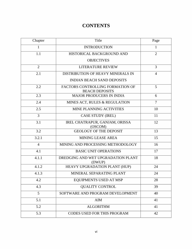
CONTENTS
Chapter Title Page
1 INTRODUCTION 1
1.1 HISTORICAL BACKGROUND AND
OBJECTIVES
2
2 LITERATURE REVIEW 3
2.1 DISTRIBUTION OF HEAVY MINERALS IN
INDIAN BEACH SAND DEPOSITS
4
2.2 FACTORS CONTROLLING FORMATION OF
BEACH DEPOSITS
5
2.3 MAJOR PRODUCERS IN INDIA 6
2.4 MINES ACT, RULES & REGULATION 7
2.5 MINE PLANNING ACTIVITIES 10
3 CASE STUDY (IREL) 11
3.1 IREL CHATRAPUR, GANJAM, ORISSA
(OSCOM)
12
3.2 GEOLOGY OF THE DEPOSIT 13
3.2.1 MINING LEASE AREA 15
4 MINING AND PROCESSING METHODOLOGY 16
4.1 BASIC UNIT OPERATIONS 17
4.1.1 DREDGING AND WET UPGRADATION PLANT
(DWUP)
18
4.1.2 HEAVY UPGRADATION PLANT (HUP) 24
4.1.3 MINERAL SEPARATING PLANT 24
4.2 EQUIPMENTS USED AT MSP 28
4.3 QUALITY CONTROL 39
5 SOFTWARE AND PROGRAM DEVELOPMENT 40
5.1 AIM 41
5.2 ALGORITHM 41
5.3 CODES USED FOR THIS PROGRAM 42

vii
6 USES AND APPLICATIONS OF HEAVY
MINERALS
49
6.1 USES OF DIFFERENT PRODUCTS 50
7 IMPEDIMENTS AND ADVANTAGES 53
7.1 IMPEDIMENTS OF PLACER MINING 54
7.2 ADVANTAGES OF PLACER MINING 54
8 CONCLUSION 55
8.1 SCOPE FOR FURTHER STUDY 55
9.0 REFERENCES 56
viii
LIST OF FIGURES
FIGURE TITLE PAGE
1 INDIAN MAP SHOWING HEAVY MINERAL
DEPOSIT
4
2 PROCESSES OF OSCOM 17
3 HIERARCHY OF OSCOM OFFICIALS 18
4 AJEYA DREDGER 20
5 FLOW CIRCUIT OF HEAVY MINERAL 21
6 PHOTOGRAPH OF SPIRAL 22
7 PRINCIPLE OF SPIRAL 23
8 CIRCUITS FOR SEPARATION OF MINERALS
AT MSP
27
9 PRINCIPLE OF HTS 28
10 PRINCIPLE OF ELECTROSTATIC SEPARATOR 29
11 PRINCIPLE OF CORONASTAT SEPARATOR 30
12 INDUCED ROLL MAGNETIC SEPARATOR 31
13 CROSS BELT MAGNETIC SEPARATOR 33
14 WET TABLES 35
15 FLOATEX DENSITY SEPARATOR 36
16 HYDROCYCLONES 38
17 PROCESS OF FLOATATION 38
18 VIEW OF FORM 1 45
19 VIEW OF FORM 2 47
20 VIEW OF FORM 3 48

ix
LIST OF TABLES
TABLE TITLE PAGE
1 FACTORS AFFECTING PLACER DEPOSITS 7
2 PROVINCE OF COASTAL REGULATION ZONE 9
3 HEAVY MINERAL RESERVES 9
4 PRODUCTION AT IREL 10
5 HEAVY MINERAL RESERVE AT OSCOM 13
6 INFORMATION ABOUT OSCOM 14
7 PROPERTIES AND CHEMICAL COMPOSITIONS
OF HEAVY MINERALS
15
8 SPECIFICATION OF SPIRAL 23
9 MINERAL SPECIFICATION AT HUP 24
10 SPECIFICATION AND IMPURITIES OF MINERALS
BEFORE MARKETING
39
11 PACKING AND PRICING 39


1
CHAPTER I
INTRODUCTION

2
1.1. HISTORICAL BACKGROUND
India is bestowed with its mineral deposits especially with a coastline of 6000 km. Heavy
mineral deposits of Manavalakuruchi in the state of Travancore (now Tamilnadu ) was
discovered by Schomberg , a German chemist in 1909 which was proved richer and economical
compared to rest of the world .
Interestingly, Mineral sands then mined from rich seasonal Beach washings for only one
mineral i.e. Monazite, which produce incandescence by infusing the paraffin mantle in a solution
of thorium and cerium compounds, lost its worth due to arrival of filament lamp.
World War I gave the British an opportunity to sieze the German -sponsored company
and Schomberg was arrested and sent to Madras. The interest of monazite importers was ceased
after 1920. First shipment of illmenite from India was effected in 1922 and production expanded
in 1940 contributing nearly 80 % of the world production which is almost 300,000 tonnes.
The Atomic Energy Commission was commissioned in 1948 by Govt. of India. Indian
Rare Earths Limited was incorporated as a private company as a joint venture with the then
Government of Travancore, Cochin in 1950 under the Indian Companies Act, 1913. IREL
became a full-fledged Govt. undertaking under DAE in 1963. OSCOM was set up during 1972,
construction had been started in 1975 and mining had been started in 1984.
Main objective of IREL is to emerge as a leading international player in the area of
mining and separation of beach sand deposits to produce minerals as well as process value added
products. It has mineral processing plants at Tamilnadu, Kerala, and Odisha, Rare Earths
division at Alwaye, Kerala and Research center at Kollam, Kerala. Its corporate offices are in
Mumbai.
Objectives of this study
1. To review the problems and prospects of sand mining in India
2. Case study of Chhatrapur sand mining complex, Odisha
3. Developing a computer program to address some of the problems

3
CHAPTER II
LITERATURE REVIEW

4
2.1. DISTRIBUTION OF HEAVY MINERALS IN INDIAN BEACH SAND DEPOSITS
India is gifted with valuable resources of beach sand minerals. Indian coast-line along Kerala,
Tamil Nadu, Odisha, and Andhra Pradesh where significant deposits of different minerals are
available is presented below. The important economic minerals are such as -
Ilmanite (FeO.TiO2)
Rutile (TiO2)
Monazite (Ce,La,Y,Th)PO4
Garnet
Sillimanite (Al2O3.SiO2)
Zircon (ZrO2.SiO2)
Varying in size, concentration and grade ranging from 5% to 45%.
FIGURE 1: INDIAN MAP SHOWING HEAVY MINERAL DEPOSITS
So far estimated Indian resources of placer minerals are (Mir Azam Ali et al., 2001).
348 million tons (mt) of ilmenite,
107 mt of garnet
21 mt of zircon

5
18 mt of rutile
130 mt of sillimanite
According to Rajamanickam et al. (2004), of the total global inferred reserves of 1775
million tones of placer minerals, India is bestowed with a reserve of :
278 million tons of ilmenite
13 million tons of rutile
18 million tones of zircon
7 million tones of monazite
86 million tones of garnet
84 million tones of sillimanite.
2.2. FACTORS CONTROLLING FORMATION OF BEACH SAND DEPOSITS
Heavy mineral sands are a class of ore deposit which is an important source of rare earth
elements and the industrial minerals such as diamond, sapphire, garnet, and other precious metals
or gemstones. Placer deposits are formed usually in beach environments by concentration due to
the specific gravity of the mineral grains. Heavy minerals (aside from gold placers) exist within
streambeds, but most are relatively small and of a low grade .The grade of a heavy mineral sand
ore deposit is usually low. Within the 21st century, the cut-off grades of heavy minerals, as a
total heavy mineral (THM) concentrate from the raw sand, in most ore deposits of this type is
around 1% heavy minerals, although several are of higher grade. Total heavy mineral
concentrate (THM), components are typically for:
Zircon- 1% to 50% of THM,
Ilmenite- 10% to 60% of THM
Rutile- 5% to 25% of THM
Leucoxene- 1% to 10% of THM
Typically magnetite, Chromite, garnet which is trash minerals usually accounts the
remaining bulk of the THM content.
The Beach sand minerals are most recently originated minerals deposits. These are
originated in southern hemisphere due to continental drifts. Due to motion between different

6
plates and repeated weathering i.e. heating and cooling, cracks are developed in between the
rocks and water gets entered into these cracks. Parent rock is subjected to weathering and erosion
and transferred along with sea water and finally sediment in a suitable basin. Continued erosion
due to air and water takes place and concentration goes on increasing with time.
The source of heavy mineral sands is within the erosional areas of a river where the
eroded minerals are dumped into the ocean, thereafter the sediments are caught up in littoral or
long shore drift. Rocks are sometimes eroded directly by the wave action and washed up onto
beaches and the lighter minerals are winnowed.
The source rocks determine the composition of the economic minerals. Usually granite is
the source of zircon, Rutile, monazite, and some Ilmenite. The source of Ilmenite, garnet is
ultramafic and mafic rocks, such as kimberlite or basalt. Garnet is sourced commonly from
metamorphic rocks, such as amphibolite schists. Precious metals are generally sourced from
deposits hosted within metamorphic rocks.
2.3. MAJOR PRODUCERS OF BEACH SAND IN INDIA
Indian Rare Earths Limited (IREL)
V.V. Minerals
Beach Mineral Company
Transworld Garnet Sand
Indian Ocean Garnet Sand
Tata Iron & Steel Company (TISCO)
7
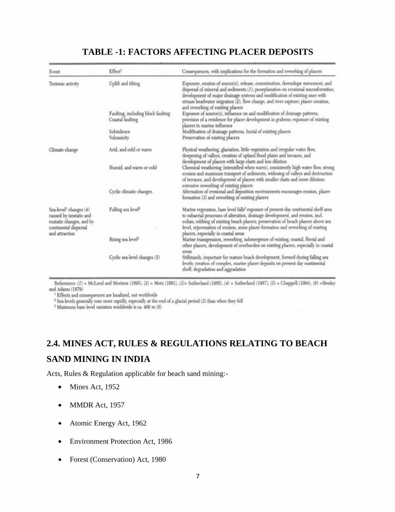
TABLE -1: FACTORS AFFECTING PLACER DEPOSITS
2.4. MINES ACT, RULES & REGULATIONS RELATING TO BEACH
SAND MINING IN INDIA
Acts, Rules & Regulation applicable for beach sand mining:-
Mines Act, 1952
MMDR Act, 1957
Atomic Energy Act, 1962
Environment Protection Act, 1986
Forest (Conservation) Act, 1980
8
Mines Rules, 1955
Mines Crèche Rules, 1966
Mines Vocational Training Rules, 1966
Mineral Concession Rules, 1960
Mineral Conservation & Development Rules, 1988
Indian Electricity Rules, 1956
Orissa Mineral Rules, 2007
Metalliferrous Mines Regulations, 1961
These mines are governed by the following Regulatory Bodies:
1. Director General of Mines Safety, Dhanbad
2. Indian Bureau of Mines, Nagpur
3. Director of Mines, Orissa
Acts, Rules and Regulations regulated / enforced by the Director General of Mines Safety are:
1. Mines Act, 1952
2. Metalliferrous Mines Regulations, 1961
3. Mines Rules, 1955
4. Mine Vocational Training Rules, 1966
5. Indian Electricity Rules, 1956
Royalty:
Section 9 of MMDR Act 1957 fixed for a period 3 years
Ilmenite/Rutile/Zircon: 2% of sale price on advolerem basis.
Sillimanite: 2.5% of sale price on advolerem basis.
Garnet: 3% of sale price on advolerem basis.
Monazite: Rs125/tonne (Ad-valorem not applicable)

9
For non-atomic minerals (Garnet & Sillimanite), sale price = IBM published value + 20%
For atomic minerals (Ilmenite, Rutile, Zircon), sale price = invoice price in case of domestic sale
= FOB or CIF price less handling expenses in case of export
Dead rent:
In case of natural calamity, if there is stoppage of production and also there is no stock for sales,
dead rent will be paid.
Environmental Protection Act, 1986:
It is also known as Umbrella Act, 1986. Coastal Regulation Zone (CRZ), February, 1991: It is
measured 500 m from the appropriate base line towards the land site and 200 m measured
towards the sea from high tide line.
TABLE-2: PROVINCE OF COASTAL REGULATION ZONE (CRZ)
TABLE-3: HEAVY MINERAL RESERVE (IN MT)

10
TABLE-4: PRODUCTION AT IREL (IN MT)
2.5. MINE PLANNING ACTIVITIES
Preliminary Investigation
Prospecting and exploration
Deposit evaluation
Selection of equipment
Set sequence of operation
Phased acquisition of land
Current Mining Activities
Guide operating personnel
Dredge path planning
Giving drilling data at closed intervals
Map showing approach road, power lines, water lines etc.
Monitor advance rate of dredge and depth of cutting
Prepare production statistics
Ensuring rehabilitation of mined out area
Promotion of ecological aspects with the help of systematic plantation
11
CHAPTER III
CASE STUDY
INDIAN RARE EARTH LIMITED

12
3.1. IREL Chhatrapur, Ganjam, Odisha (OSCOM)
On August 18th, 1950 Indian Rare Earths Limited (IREL) was incorporated as a private limited
company, jointly owned by the Government of India and Government of Travancore, Cochin
with the primary intention of taking up commercial scale processing of monazite sand at its first
unit namely Rare Earths Division (RED) Aluva, Kerala for the recovery of thorium.
After becoming a fully fledged Central Government Undertaking in 1963 under the
administrative control of Department of Atomic Energy (DAE), IREL took over a number of
private companies engaged in mining and separation of beach sand minerals in southern part of
the country and established two more Divisions one at Chavara, Kerala and the other at
Manavalakurichi (MK), Tamil Nadu.
After a gap of about 20 years, IREL commissioned its largest Division called Orissa Sand
Complex (OSCOM) at Chatrapur, Ganjam, Odisha. Today IREL operates these units with
Corporate Office in Mumbai and produces/sells six heavy minerals namely Ilmenite, Monazite,
Sillimanite, Rutile, Zircon, and Garnet as well as various value added products.
OSCOM was commissioned at a place called Chatrapur about 150 Kms from
Bhubaneswar and about 320 km from all weather seaports Visakhapatnam to exploit the huge
placer deposit across a mining area of 24.64 km2 to produce 2,20,000 ton Ilmenite having 50%
TiO2 content and associated minerals like Sillimanite, Rutile, Zircon, Garnet, etc. For the first
time IREL ventured into dredging and concentration operation at OSCOM. It is quite efficiently
engaged in dredging of the raw sand, its upgradation, drying and finally separation plant.
Customers imported illmenite primarily for the production of slag and sulphatable TiO2 pigment.
From 1992, A Thorium plant is in operation at OSCOM to produce 240 tpa mantle grade
Thorium Nitrate.
13
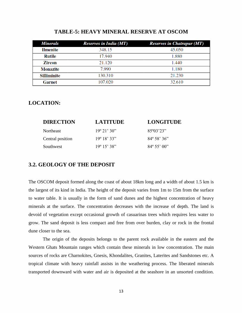
TABLE-5: HEAVY MINERAL RESERVE AT OSCOM
LOCATION:
DIRECTION LATITUDE LONGITUDE
Northeast 19º 21’ 30” 85º03’23”
Central position 19º 18’ 33” 84º 58’ 36”
Southwest 19º 15’ 38” 84º 55’ 00”
3.2. GEOLOGY OF THE DEPOSIT
The OSCOM deposit formed along the coast of about 18km long and a width of about 1.5 km is
the largest of its kind in India. The height of the deposit varies from 1m to 15m from the surface
to water table. It is usually in the form of sand dunes and the highest concentration of heavy
minerals at the surface. The concentration decreases with the increase of depth. The land is
devoid of vegetation except occasional growth of casuarinas trees which requires less water to
grow. The sand deposit is less compact and free from over burden, clay or rock in the frontal
dune closer to the sea.
The origin of the deposits belongs to the parent rock available in the eastern and the
Western Ghats Mountain ranges which contain these minerals in low concentration. The main
sources of rocks are Charnokites, Gnesis, Khondalites, Granites, Laterites and Sandstones etc. A
tropical climate with heavy rainfall assists in the weathering process. The liberated minerals
transported downward with water and air is deposited at the seashore in an unsorted condition.

14
Rushikulya River acted as transportation agent for the heavy minerals and deposited it in Bay of
Bengal.
TABLE-6: INFORMATION ABOUT OSCOM
The actual sorting and concentration takes place due to two principal agents. A breaking wave
takes the foreshore minerals to the beach and the backwash carries the lighter minerals back to
the sea. And this to and fro action of waves results in sorting and the concentration of heavy

15
minerals in beach placer deposit. Action of the wind enriches the concentration by blowing the
finer and the lighter sand particles. The OSCOM deposit can be classified into two sectors viz.
south and north for the purpose of evaluation and presentation of the deposit.
3.2.1. Mining Lease Area
2877.76 Hectares from 21/03/1979 to 20/03/1999
2464.054 Hectares from 21/03/1999 to 20/03/2019
TABLE-7: Properties & Chemical Composition of HEAVY Minerals

16
CHAPTER IV
MINING AND PROCESSING
METHODOLOGY
17
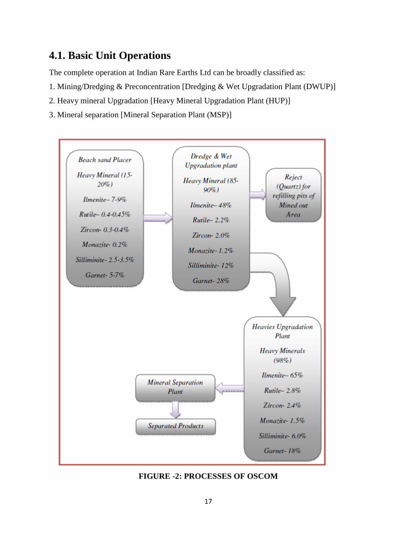
4.1. Basic Unit Operations
The complete operation at Indian Rare Earths Ltd can be broadly classified as:
1. Mining/Dredging & Preconcentration [Dredging & Wet Upgradation Plant (DWUP)]
2. Heavy mineral Upgradation [Heavy Mineral Upgradation Plant (HUP)]
3. Mineral separation [Mineral Separation Plant (MSP)]
FIGURE -2: PROCESSES OF OSCOM

18
FIGURE -3: HIERARCHY OF OSCOM OFFICIALS
4.1.1. Dredging and Wet Upgradation Plant (DWUP)
The OSCOM have a huge placer deposit with a length of 18 Kms and width of 1.5 Kms running
parallel to the coast of Bay of Bengal. Northern boundary of the mining area is Rusikulya River
and southern boundary is Gopalpur town. The estimated reserves are 230 MT (1.5m below MSL)
and 440 MT (6m below MSL). Mining is divided in two sections; North section and South
section. The whole mining area is classified in three zones; plenty zone, Intermediate zone and
rare zone.
This plant is in complete floating condition. It floats in a pond having diameter 200m and
depth of 6m. The whole unit can be divided in two groups:
1) Mining/dredging
2) Pre-concentration
Mining:
The mining procedure followed for the excavation of beach sand is completely different from the
surface or underground mining. The procedure followed is commonly known as DREDGING.

19
Dredging can be defined as an excavation activity or operation which is carried out at partly
underwater, in shallow depth of sea or fresh water areas with the purpose of gathering up bottom
sediments and disposing of them at a different location. A dredge is a device used for dredging
for scraping or sucking the seabed. A dredger is a boat or ship equipped with a dredge. The
process of dredging creates wastes (excess material), which are conveyed to another location
different from the dredged area. The dredge Capacity is about 500 TPH and dredge depth is
nearly 6m. The RPM of the motor used is 368 with a power of 525KW.In OSCOM, There are
two different types of dredge used for dredging purposes:
Cutter Suction Dredge: A cutter-suction dredger's (CSD) suction tube has a cutter head at the
suction inlet, used to loosen the earth and convey it to the suction mouth. The cutter can also be
used for hard surface materials like gravels or rocks. The dredged material is usually sucked up
by a wear-resistant centrifugal pump which is discharged through a pipe line or to a barge. In
recent years, in order to excavate harder rock without blasting, dredgers with more powerful
cutters have been built.
Bucket wheel Dredge: The bucket-wheel dredge is identical to the cutter suction dredge apart
from the position of wheel excavator which is used in lieu of the rotary cutter. In both the cases,
the cutter attached to the ladder rotates and cuts the sand and thus make a suspension of sand in
water which is pumped out to the Trommel.
Pre-concentration:
In this stage, the amount of heavies is upgraded up to 90%. Then it is sent to HUP for further
treatment. The suspension formed by the dredger is pumped to the Trommel with aperture size is
4mm, which rotates at 6RPM with a motor power of 37KW. The undersize of the Trommel is
sent to bins from where it is sent to the spirals for concentration and the oversize usually
containing pebbles, grass and other waste materials. In spirals 4-stage of cleaning takes place i.e.
Rougher, Cleaner, Recleaner and Scavenger. Each spiral with 144 starts and each used at 2TPH
and the total capacity is 576 TPH. Concentrate from the rougher spirals is sent to cleaner spirals,
middlings to Scavenger spirals and tailings to the Hydrocyclone from where the overflow (water)
is sent to Trommel discharge and the underflow is the rejects (sand) which is thrown for back

20
filling of the pits. Cleaner concentrate is sent to Recleaner, middlings is recirculated and tailings
to the scavenger. Recleaner concentrate is final concentrate which is sent to HUP (Heavy
upgradation plant), middlings is recirculated and tailings are sent to cleaner. The scavenger
concentrate is sent to cleaner circuit, middlings is recirculated and tailings are sent to
Hydrocyclone. By this process the amount of heavies are improved to 90-92%.
FIGURE -4: AJEYA DREDGER AT OSCOM

21
FIGURE -5: FLOW CIRCUIT OF HEAVY MINERAL
Spirals
Spirals are gravity separators where slurry is fed to at a pulp density of about 20-25%, the size
range is commonly 3mm to 75 microns and as the slurry flows down the curved channel, lighter
particles due to action of centrifugal forces will report to the outer area of the spirals as tails
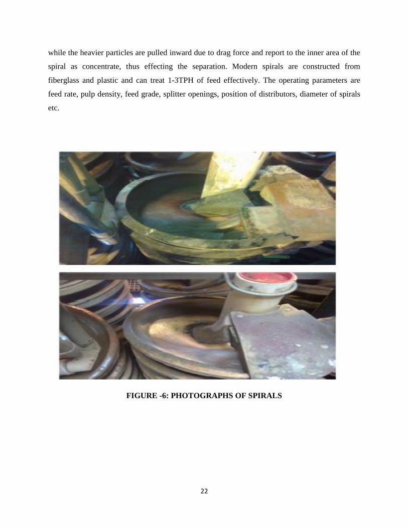
22
while the heavier particles are pulled inward due to drag force and report to the inner area of the
spiral as concentrate, thus effecting the separation. Modern spirals are constructed from
fiberglass and plastic and can treat 1-3TPH of feed effectively. The operating parameters are
feed rate, pulp density, feed grade, splitter openings, position of distributors, diameter of spirals
etc.
FIGURE -6: PHOTOGRAPHS OF SPIRALS
23
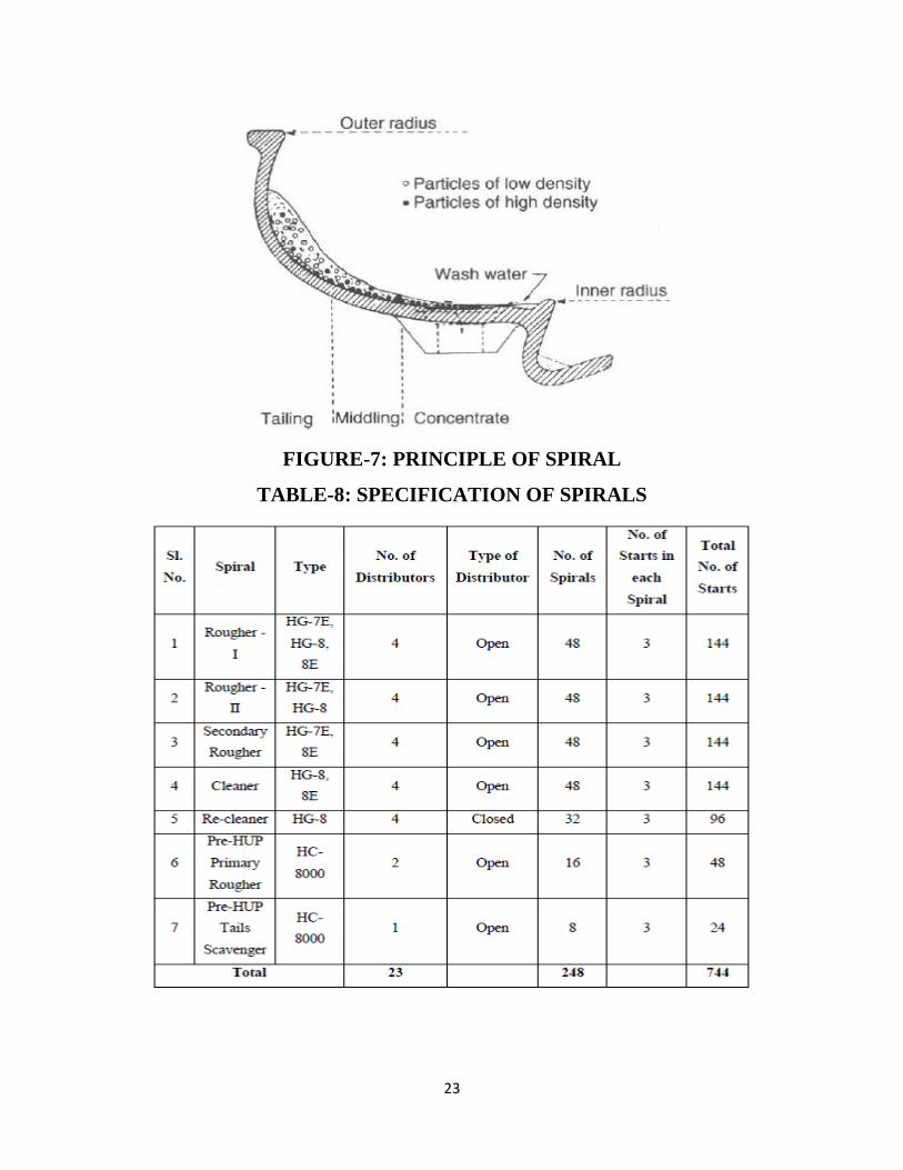
FIGURE-7: PRINCIPLE OF SPIRAL
TABLE-8: SPECIFICATION OF SPIRALS

24
4.1.2. Heavy Upgradation Plant (HUP)
This is the stage where the concentration of heavy is further upgraded to 98%. The feed to HUP
plant is the Recleaner concentrate of the DWUP where heavy minerals concentration is 90-92%.
The heavy minerals are received from Dredge and Wet upgradation plant (DWUP) at the Re-
pulping area of Mineral Separation Plant (MSP). These materials are pumped for up gradation in
heavy Upgradation Plant (HUP) at MSP. When HUP is not in operation the material is stockpiled
at RPA. These accumulated heavies are pushed for pumping to HUP be the help of Earth Moving
Equipments (EMEs) whenever required. In HUP, the feed is treated in gravity separation
equipment like spirals and Hydrocyclones and the unwanted lighter material is pumped to reject
dumping yard and the upgraded heavy mineral is pumped to the dry feed yard through
Hydrocyclones for natural dewatering and finally it is fed to main plant by EMEs for drying and
further separation.
TABLE -9: MINERAL SPECIFICATION AT HUP
4.1.3. Mineral Separation Plant (MSP)
In the mineral separation plant (MSP), the heavy minerals like Ilmenite, Rutile, monazite, zircon
and Silliminite are separated from the upgraded feed minerals on the basis of their physical
properties like electrostatic & magnetic property, surface characteristics and specific gravity. The

25
plant comprised of different floor and equipped with different material handling equipment like
bucket elevators, belt conveyors, screw conveyors, drag conveyors to facilitate smooth transport
of materials to the desired machines for example Rotary Dryer, High tension separators,
Magnetic separators, Shaft dryers, Electrostatic Separators etc. Beside this, there is a wet
processing circuit which comprises of Spirals, Floatex, Wet Tables, Flotation cells etc and Slurry
Pumps are used to transport materials from one point to another.
Annual Production Capacity of MSP
Ilmenite: 220000 TPA
Rutile: 7400 TPA
Zircon: 5000 TPA
Sillimanite: 8000 TPA
Monazite: 2350 TPA
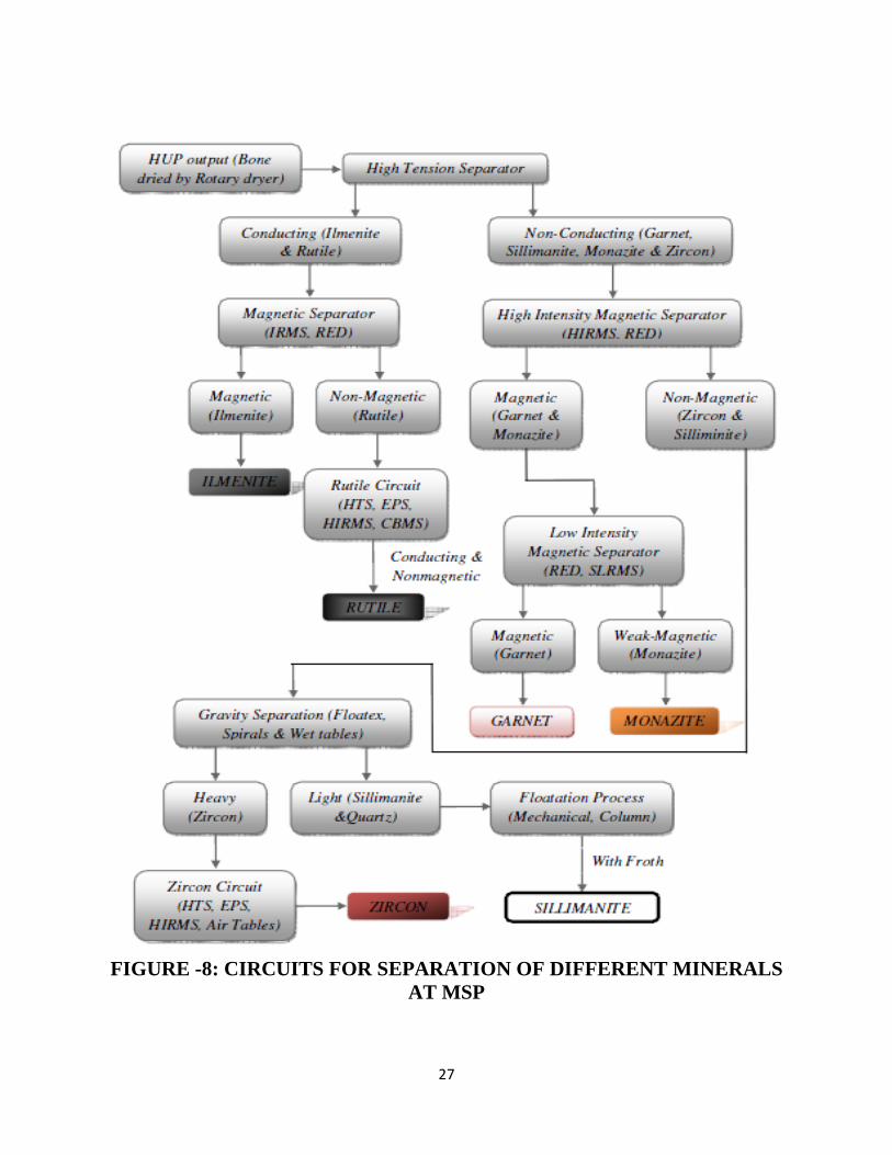
Ilmenite Circuit
The first activity in the MSP includes the drying of the feed material by rotary dryer of 50TPH
capacity using Furnace Oil. In the next operation, the bone dried feed (140-150oC) material is
fed for High Tension Separators (HTS) where conducting minerals like Ilmenite and Rutile are
separated from non-conducting minerals like Zircon, Monazite, Garnet and Sillimanite. Then, the
conducting part is fed to Induced Roll Magnetic Separators (IRMS) and Ilmenite being magnetic,
separated out from nonmagnetic Rutile and stored in Ilmenite ware house. For further recovery
of the products, the middling fraction of High Tension Separator and IRMS are treated in Shaft
Dryers followed by HTS, Electrostatic Separators (ESP), Rare Earth Drum Magnetic Separators
(RED) and IRMS etc.
Rutile Circuit
The Rutile has conducting and nonmagnetic property is being produced by treating the
nonmagnetic fraction of IRMS, REDs etc in Rutile circuit consists of a shaft dryer, HTS, EPS,

26
High Intensity Induced Magnetic Separators (HIRMS), Cross Belt magnetic Separator (CBMS)
and vibratory screen etc. Then the Rutile product from the circuit is collected in hoppers
followed by bagging in 50kg bags in ware house.
Monazite Circuit
The non conducting fraction is fed to HIRMS followed by REDs to separate the feebly magnetic
Monazite and magnetic Garnet from it. Then Garnet part is sent to the reject yard along with the
HUP rejects. For further recovery of Monazite from feebly magnetic fraction is treated in Semi
Lift Magnetic Separators (SLMS) and Air tables. The Monazite product is at present pumped to
trench located in specified area for future use. Monazite is being a radioactive mineral in nature
the processing area is protected by barricading for trespassers and the radiation level in the
Monazite circuit at different level is monitored by the Health Physics Unit under BARC at
OSCOM.
Zircon Circuit
The non conducting nonmagnetic fraction is then treated in Wet circuit consisting of Floatex
density Separator, Spirals, Wet tables etc to separate Zircon and Sillimanite rich fraction from it.
The heavier fraction of this circuit is mainly Zircon, which is dried in a Rotary Dryer followed
by operation in HTS and Air table for further purification. Then the Zircon product is collected
in hopper followed by bagging in 50kg bags in ware house.
Sillimanite Circuit
The lighter fraction in the wet circuit is mainly Sillimanite, which is separated from the
unwanted quartz in froth flotation operation by using different chemicals like sodium silicate
(depressant for quartz), soda ash (pH modifier), oleic acid (frother) etc. Finally the sillimanite is
dried in a dryer followed by magnetic operation and stored in ware house. Apart from the above
to support the dryers heating system, there is a furnace oil handling system consisting of a day
tank capacity of 20KL and three screw pumps for pumping furnace oil to different dryers.
27
FIGURE -8: CIRCUITS FOR SEPARATION OF DIFFERENT MINERALS
AT MSP

28
4.2. Equipments Used at MSP
Electrical Separators
Electrical separators utilize the difference in electrical conductivity between the various minerals
in the ore feed. Since almost all minerals show some difference in conductivity it would appear
to represent the universal concentrating method. The fact that the feed must be perfectly dry
imposes limitations on the process, but it also suffers from the some disadvantage as, the
capacity is very small for finely divided material. For most efficient operation, the feed should be
in a layer, one particle deep, which severely restricts the throughput if the particles are as small
as, say, 75 microns. In MSP, there are three different types of Electrical Separators which are
being used depending upon the requirement.
High Tension Separator
High tension separator (HTS) utilizes the differences in surface conductivities of conducting and
non conducting minerals thereby affecting their separation by pinning/lifting non conducting
particles and throwing conducting particles with the help of electrodes. In MSP, HTS is used for
the initial separation of conducting minerals from the non-conducting.
FIGURE-9: PRINCIPLE OF High Tension Separator

29
Electrostatic Separators
Final cleaning of the HTS products is often carried out in purely electrostatic separators, which
employ the "lifting effect" only. The feed particles gravitate down a sloping, grounded plate into
an electrostatic field induced by a large, oval, high-voltage electrode.
FIGURE -10: PRINCIPLE OF Electrostatic Separators
Coronastat Separator
It separates minerals based on their differences in surface conductivities using a unique
combination of three electrodes. Each electrode has a unique function. The ionizing electrode
ionizes the feed particles; the induction electrode forces the decay of charged conducting
particles while the capacitance electrode applies a holding force to non-conducting particles as
they travel through the separation zone, thus effecting the proper separation. The operating
parameters are once again same as the HTS.

30
FIGURE -11: PRINCIPLE OF Coronastat Separator
There are five different types of magnetic separators used at MSP.
Induced Roll Magnetic Separators
Magnetic field is produced when an electric current (D.C.) is passed through a coil of wire (the
induction process). The magnetic field intensity generated in an electro-magnetic separator is
dependent upon:
Amplitude of current (amps) – Variable
Number of turns in coil (Windings) – Fixed
The length of the iron circuit – Fixed
Magnetic permeability of iron circuit (This includes the air gap in iron circuit necessary for
separation zone)

31
FIGURE -12: Induced Roll Magnetic Separators
The operating parameters are
Magnetic field current
Air gap
feed rate
roll speed
splitter position
Generally feed rate is maintained at 4-5TPH per roll and the roll speed is around 150RPM.

32
Lift Roll & Semi Lift Roll Magnetic Separator
These are a different kind of magnetic separator where the magnetic particles are lifted by the
roll under the action of magnetic field. It is used in Monazite circuit. These are high intensity
magnetic separators to separate two or more variable magnetic susceptible minerals to separate
as magnetic and non magnetic. These separators are used to separate Garnet from Monazite,
Rutile from Leucoxene in beach sand minerals. The principle involved is the grounded roll is
provided in between two magnetic blocks. The magnetic flux generated from the bottom of the
roll directed towards upward direction. The roll having groove type surface, convergent magnetic
field is generated around 19-10 Kilogauss is sufficient to lift Garnet particles from the monazite
as garnet is moderately magnetic in nature and collected in the magnetic fraction. The feebly
magnetic particles are collected in a separate chamber. The capacity of these separators is found
to be 0.5 to 1.0 tons per hour for effective separation.
Rare earth Drum Magnetic Separators
Rare earth drum separator (REDS) is a kind of magnetic separator which separates the minerals
on the basis of their difference in magnetic properties. It works on similar principle as the
Induced roll magnetic separator but it differs in its basic construction and its operation. In this
the magnetic field is produced by permanent magnets. The magnetic element is constructed with
the help of blocks of Neodymium Iron Boron ceramic magnets, Iron or steel pole are not used in
this configuration i.e. an ironless design. The magnetic element consists of five main magnetic
poles; each pole consists of two magnetic blocks. There are also two trailing poles to provide
“Diminishing” magnetic field intensity. This configuration generates a peak magnetic field
intensity of 6-7 Kilogausses on the drum surface. The magnetic circuit remains stationary within
the drum shell and spans an arc of approximately 1200. A single RED can treat up to 5 TPH
effectively. A release mechanism is provided to dislodge minor amounts of ferromagnetic
material from the drum surface.

33
The operating parameters are:
feed rate
roll speeds
feed temperature
splitter positions
Cross Belt magnetic Separators
It is a high intensity magnetic separator in which feed is allowed to pass through a main belt and
a number of cross belts. Magnetic particles get attracted to the bottom part of the cross belt due
to the influence of electromagnet placed over the cross belt which carries them out of magnetic
field while non-magnetic particles pass on unaffected. The magnetic field is in the range of about
19-20 Kilogauss and the capacity is about 1.5-2.0TPH.
FIGURE -13: Cross Belt magnetic Separators

34
The operating parameters are:
magnetic field current
Air gap
Belt speed
feed rate
Gravity Concentrator
Gravity concentration methods separate minerals of different specific gravity by their relative
movement in response to gravity and one or more other forces, the latter offers resistance to the
motion by a viscous fluid, such as water or air. Different kinds of gravity concentrators are being
used in MSP.
Wet Tables
Wet table consists of an inclined deck fitted with riffles. With given reciprocating motion at right
angle to the flow of water, heavier minerals settle down in the riffles and concentrates are carried
along the diagonal line of the table. The lighter minerals cannot settle in the riffles and are
washed along with the water as tailings. The pulp density we generally maintain is 25-30% of
solid.
The operating parameters are:
quantity of wash water
deck slope
feed rate
stoke length
speed
pulp density

35
FIGURE -14: Wet Tables
Air Tables
Air tables are gravity concentrators which use air as a separating medium. Compressed air is
allowed below the vibrating table whose surface is covered with a perforated cloth. The feed is
supplied near the top of the inclined table. Lighter particle are lifted by the air and flow
downwards as tailings. The oscillating motion of the table causes the heavy minerals in contact
with the table surface to move upward and is collected as concentrate.
Operating parameters are:
quantity of air
feed rate
deck inclination
splitter opening
stoke length
speed
36
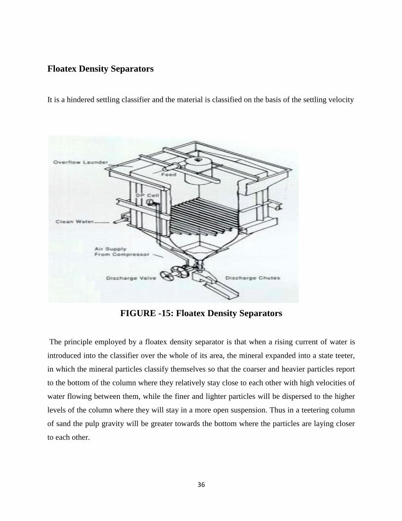
Floatex Density Separators
It is a hindered settling classifier and the material is classified on the basis of the settling velocity
FIGURE -15: Floatex Density Separators
The principle employed by a floatex density separator is that when a rising current of water is
introduced into the classifier over the whole of its area, the mineral expanded into a state teeter,
in which the mineral particles classify themselves so that the coarser and heavier particles report
to the bottom of the column where they relatively stay close to each other with high velocities of
water flowing between them, while the finer and lighter particles will be dispersed to the higher
levels of the column where they will stay in a more open suspension. Thus in a teetering column
of sand the pulp gravity will be greater towards the bottom where the particles are laying closer
to each other.

37
Hydrocyclones
Hydrocyclone is a classifying device that utilizes the centrifugal force to accelerate the settling
rate of particles. A typical Hydrocyclone consists of a conically shaped container, open at its
apex or underflow, connected to a cylindrical section, with a tangential feed inlet. The top
opening is closed with the help of a plate through which passes an axially mounted overflow
pipe. The feed is introduced under pressure through the tangential entry which imparts a swirling
motion to the pulp. This generates a vortex in the cyclone, with a low-pressure zone along the
vertical axis. An air core develops along the axis, normally connected to the atmosphere through
the apex opening, but in part created by dissolved air coming out of solution in the zone of low
pressure. Feed particles in the pulp are subjected to two opposing forces viz. an outward
centrifugal force and an inward drag force. The centrifugal force causes coarse and heavy
particles to report as underflow while the action of the drag force results in fine and light
particles reporting as underflow.
The operating parameters are:
feed inlet diameter
spigot diameter
vortex finder diameter
feed pressure
pulp density
cut size
Flotation
Flotation is a process where the desired mineral particles in pulp are selectively floated by their
attachment to rising bubbles. In MSP, slurry containing sillimanite and quartz is conditioned in
the first stage with sodium silicate and soda ash.
Operating parameters are:
slurry pH
air pressure
froth depth
reagent dosage

38
air flow
feed rate
Quantity of wash water
conditioning time
feed rate
FIGURE -16: Hydrocyclones
FIGURE -17: PROCESS OF Flotation
39
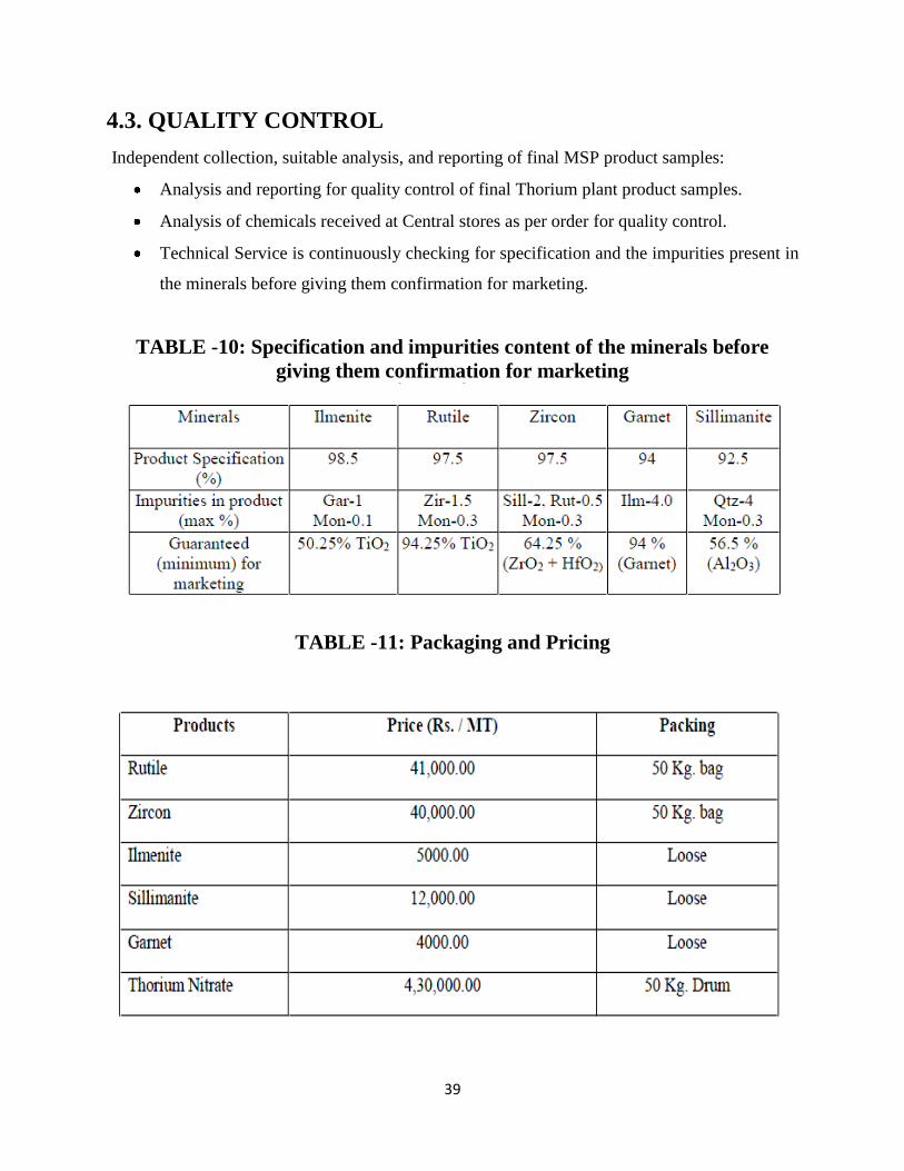
4.3. QUALITY CONTROL
Independent collection, suitable analysis, and reporting of final MSP product samples:
Analysis and reporting for quality control of final Thorium plant product samples.
Analysis of chemicals received at Central stores as per order for quality control.
Technical Service is continuously checking for specification and the impurities present in
the minerals before giving them confirmation for marketing.
TABLE -10: Specification and impurities content of the minerals before
giving them confirmation for marketing
TABLE -11: Packaging and Pricing
40
CHAPTER V
SOFTWARE AND PROGRAM
DEVELOPMENT

41
5.1. AIM
This program is encrypted having an intension of estimating the heavy mineral and the tailings
generated in some processes with an approximate value before extraction which would help the
authority to achieve production target and also provide cynosure for waste management.
This runs in Microsoft visual studio and coded in C# language.
5.2. ALGORITHM
Let dredged material input be x tons.
Percentage of heavy mineral content be y (14-18%).
DWUP
Let Trommel efficiency be z (i.e. 90-95%)
Trommel filter capacity quotient = 0.75.
Retained material or Output a is
Tailings, at is
Spirals
Let spiral efficiency be u (i.e. 95-98%)
Spiral filter capacity quotient = 0.35
Retained Material or output, b is
Tailings, bt is
Separators
Let separator efficiency be v (i.e. 99-100%)
Output, c is
Tailings, d is

42
Final Compositions
Ilmenite = c x 0.675
Rutile = c x 0.035
Zircon = c x 0.036
Monazite = c x 0.02
Silimanite = c x 0.07
Garnet = c x 0.155
Procedure
Open Microsoft Visual Studio.
Open Project “Project.sln”.
Press F5 to execute.
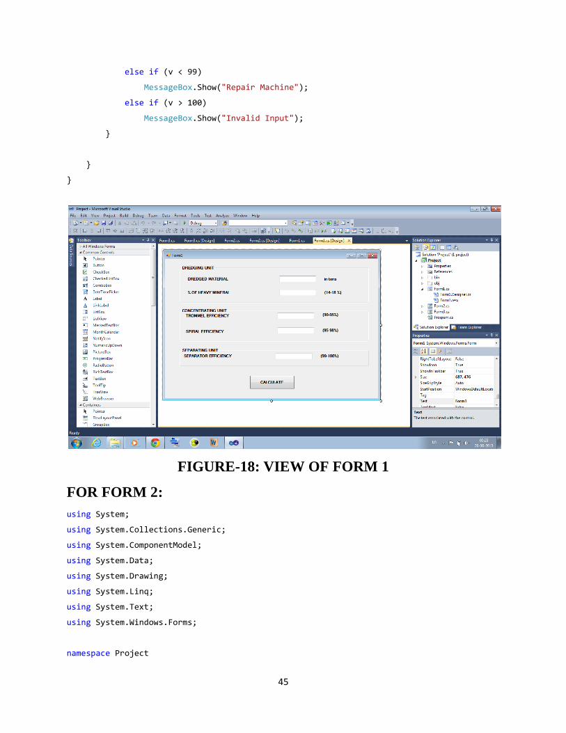
As the windows form appears, enter the inputs and click on “Calculate”.
Next window opened will show the desired output.
5.3. CODES USED FOR THIS PROGRAM ARE GIVEN BELOW:
FOR FORM 1:
using System;
using System.Collections.Generic;
using System.ComponentModel;
using System.Data;
using System.Drawing;
using System.Linq;
using System.Text;
using System.Windows.Forms;
namespace Project
{

43
public partial class Form1 : Form
{
public Form1()
{
InitializeComponent();
}
private void button1_Click(object sender, EventArgs e)
{
double a, at, b, bt, c, d;
double x= double.Parse(textBox1.Text);
double y= double.Parse(textBox2.Text);
double z= double.Parse(textBox3.Text);
double u= double.Parse(textBox4.Text);
double v= double.Parse(textBox5.Text);
if (y==1)
MessageBox.Show("UNECONOMICAL");
if (z==9)
MessageBox.Show("Repair Machine");
if (u==9)
MessageBox.Show("Repair Spiral");
if ((v == 9) || (v == 1) || (v == 10))
MessageBox.Show("Repair Separator");
a = x - (x * 0.75 * z * 0.01);
at = x - a;
b = a - (a * 0.35 * u * 0.01);
bt = a - b;
c = (y - (0.05 * y)) * v * x * 0.01*0.01;
d = b - c;
Form2 f = new Form2(c,at,bt,d);
f.Show();
}
private void textBox2_TextChanged(object sender, EventArgs e)
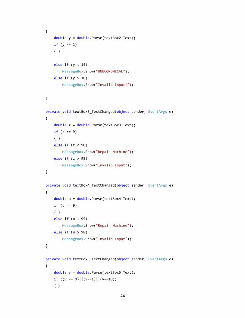
44
{
double y = double.Parse(textBox2.Text);
if (y == 1)
{ }
else if (y < 14)
MessageBox.Show("UNECONOMICAL");
else if (y > 18)
MessageBox.Show("Invalid Input!");
}
private void textBox3_TextChanged(object sender, EventArgs e)
{
double z = double.Parse(textBox3.Text);
if (z == 9)
{ }
else if (z < 90)
MessageBox.Show("Repair Machine");
else if (z > 95)
MessageBox.Show("Invalid Input");
}
private void textBox4_TextChanged(object sender, EventArgs e)
{
double u = double.Parse(textBox4.Text);
if (u == 9)
{ }
else if (u < 95)
MessageBox.Show("Repair Machine");
else if (u > 98)
MessageBox.Show("Invalid Input");
}
private void textBox5_TextChanged(object sender, EventArgs e)
{
double v = double.Parse(textBox5.Text);
if ((v == 9)||(v==1)||(v==10))
{ }
45
else if (v < 99)
MessageBox.Show("Repair Machine");
else if (v > 100)
MessageBox.Show("Invalid Input");
}
}
}
FIGURE-18: VIEW OF FORM 1
FOR FORM 2:
using System;
using System.Collections.Generic;
using System.ComponentModel;
using System.Data;
using System.Drawing;
using System.Linq;
using System.Text;
using System.Windows.Forms;
namespace Project
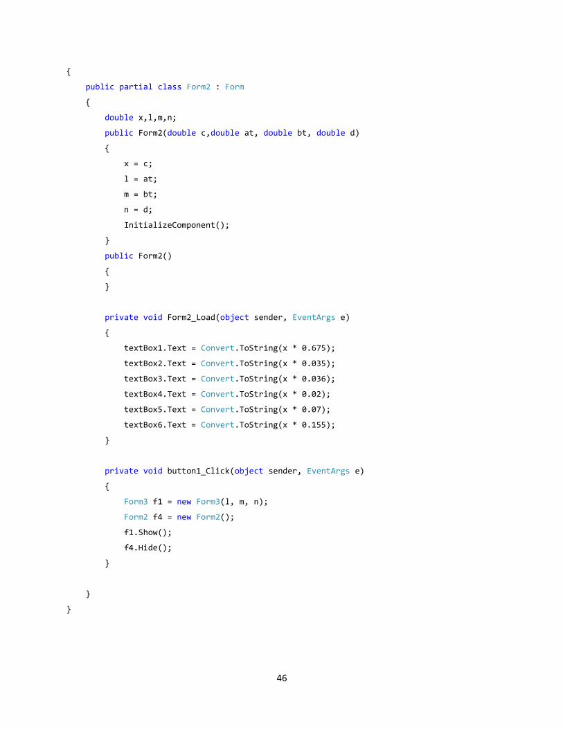
46
{
public partial class Form2 : Form
{
double x,l,m,n;
public Form2(double c,double at, double bt, double d)
{
x = c;
l = at;
m = bt;
n = d;
InitializeComponent();
}
public Form2()
{
}
private void Form2_Load(object sender, EventArgs e)
{
textBox1.Text = Convert.ToString(x * 0.675);
textBox2.Text = Convert.ToString(x * 0.035);
textBox3.Text = Convert.ToString(x * 0.036);
textBox4.Text = Convert.ToString(x * 0.02);
textBox5.Text = Convert.ToString(x * 0.07);
textBox6.Text = Convert.ToString(x * 0.155);
}
private void button1_Click(object sender, EventArgs e)
{
Form3 f1 = new Form3(l, m, n);
Form2 f4 = new Form2();
f1.Show();
f4.Hide();
}
}
}

47
FIGURE-19: VIEW OF FORM 2
FOR FORM 3:
using System;
using System.Collections.Generic;
using System.ComponentModel;
using System.Data;
using System.Drawing;
using System.Linq;
using System.Text;
using System.Windows.Forms;
namespace Project
{
public partial class Form3 : Form
{
double p, q, r;
public Form3(double l,double m,double n)
{
p = l;
q = m;
r = n;
InitializeComponent();
}

48
public Form3()
{
}
private void Form3_Load(object sender, EventArgs e)
{
textBox1.Text = Convert.ToString(p);
textBox2.Text = Convert.ToString(q);
textBox3.Text = Convert.ToString(r);
}
private void button1_Click(object sender, EventArgs e)
{
Form1 f2 = new Form1();
f2.Show();
Form3 f3 = new Form3();
f2.Show();
f3.Hide();
}
}
}
FIGURE-20: VIEW OF FORM 3

49
CHAPTER VI
USES AND APPLICATIONS OF HEAVY
MINERALS
50
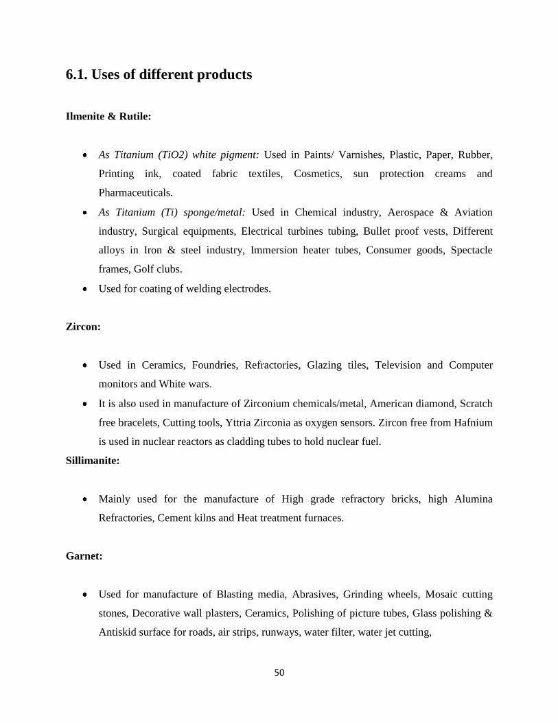
6.1. Uses of different products
Ilmenite & Rutile:
As Titanium (TiO2) white pigment: Used in Paints/ Varnishes, Plastic, Paper, Rubber,
Printing ink, coated fabric textiles, Cosmetics, sun protection creams and
Pharmaceuticals.
As Titanium (Ti) sponge/metal: Used in Chemical industry, Aerospace & Aviation
industry, Surgical equipments, Electrical turbines tubing, Bullet proof vests, Different
alloys in Iron & steel industry, Immersion heater tubes, Consumer goods, Spectacle
frames, Golf clubs.
Used for coating of welding electrodes.
Zircon:
Used in Ceramics, Foundries, Refractories, Glazing tiles, Television and Computer
monitors and White wars.
It is also used in manufacture of Zirconium chemicals/metal, American diamond, Scratch
free bracelets, Cutting tools, Yttria Zirconia as oxygen sensors. Zircon free from Hafnium
is used in nuclear reactors as cladding tubes to hold nuclear fuel.
Sillimanite:
Mainly used for the manufacture of High grade refractory bricks, high Alumina
Refractories, Cement kilns and Heat treatment furnaces.
Garnet:
Used for manufacture of Blasting media, Abrasives, Grinding wheels, Mosaic cutting
stones, Decorative wall plasters, Ceramics, Polishing of picture tubes, Glass polishing &
Antiskid surface for roads, air strips, runways, water filter, water jet cutting,

51
Artificial Granite tiles/Heavy duty floor tiles, cleaning of casings/pipes in petroleum
industry and as a gemstone.
Monazite:
Extraction of thorium concentrate and rare earth compounds.
Rare earth chlorides: Widely used in the manufacture of Misch metal used for lighter
flints, for the production of catalysts for cracking, for the manufacture of metallic soaps
which is used as Dryer in paints, starting material for the production of pure rare earths &
rare earth compounds, removal of organic impurities and decolourisation of paper mills
effluents and for the manufacture of special ferrous casting.
Rare earth Fluorides: Used in manufacture of arc carbon electrodes to increase the arc
intensity, rare earth alloys, for production of nodular cast iron, special steels.
Rare earth Oxides: In the arc carbon industries to increase the arc intensity by factor
ten, the emitted light is identical to natural sun light, for glass polishing in Optical.
Cerium oxide: Used in Polishing optical lenses, plate glasses, TV tube face plates; prism
etc. finds application in semiconductor devices, UV absorber in Glasses, radiation
protective glasses, yellow color and decolorizing etc.
Cerium hydrates: Used in manufacture of polishing composition, in the decolorizing of
glass, as an opacifier, as an ingredient in Ultraviolet.
Didymium compound: Use in manufacture of pure rare earth compound, in glass,
ceramics, and nuclear & electronic industries and for improving the workability of
stainless steel alloys.
Samarium oxide: For the extraction of samarium metal this finds use in manufacture of
samarium cobalt; used as permanent magnet with high coercive force and high magnetic
energy.
Gadolinium oxide: In the manufacture of Gadolinium-Gallium-Garnet (GGG) substrates
of magnetic bubbles and Microwave garnets.
Yttrium oxide: In the manufacture of phosphor for color tubes and Fluorescents tubes,
super conductors and artificial gems.

52
Europium oxide: As an activator in preparing phosphors for color TV tubes &
fluorescent lamps.
Europium: Three bond lamps, cathode ray tubes (CRT), flat plasma TV screen and
phosphors.
Terbium: Luminescence, phosphors.
Dysprosium: Luminescence, phosphors, application for nuclear industry, ceramics.
Holmium: Application for nuclear industry, ceramics, laser.
Erbium: Nuclear reactors, ceramics, glass coloring, optic fibers, medical applications,
laser.
Thorium Nitrate: Gas handling Industry
Thorium Oxide: Fluorescence tubes & starters; Catalyst for Petroleum industry
Uranium Oxide: Nuclear Industry
Tri sodium phosphate: Descaling, Degreasing, Detergents.

53
CHAPTER VII
IMPEDIMENTS AND ADVANTAGES

54
7.1. IMPEDIMENTS OF PLACER MINING
Land Acquisition is an issue. The area under lease has decreased owing to various social
& environmental issues.
These minerals are strategic assets. Secrecy is maintained according to shipment and
production data.
The CRZ notification has further divested IREL for carrying out dredging activities
within 100 meters of the High Tide Line.
Fresh water availability for the artificial pond is minimized.
Dredging creates disturbances to the aquatic ecosystems. Dredge spoils may contain toxic
chemicals which have an adverse impact on the disposal area; The process of dredging
often dislodges chemicals residing into the water column.
The following impacts to the environment due to the activity of dredging :
Release of toxic chemicals like heavy metals and PCB
Increase in turbidity, which affects aquatic species metabolism
Secondary effects from water column contamination of uptake of DDT ,heavy metals,
other persistent organic toxins, via food chain uptake and concentrations of these toxins
in higher organisms including humans.
Difficulty in marsh productivity from sedimentation
Impacts to avifauna as they have to prey upon contaminated aquatic organisms
Secondary impacts to the aquatic and benthic organisms' mortality and metabolism.
7.2. ADVANTAGES OF PLACER MINING
Processing and transport cost is reduced up to 40-50% as these are loose materials.
Safety issues are not major as compared to underground mining.
The deposits in Orissa were very old; however in Kerala and Kanyakumari, still the
deposits are being readily formed and extracted by beach washing.
55
CHAPTER VIII
8.0. CONCLUSION
Indian Rare Earths Ltd. is one among the public sector, which has an outstanding performance in
the processing of beach sand minerals available along the coastal belt. The organization study in
this unit is an unforgettable experience. The work culture is gratifying and also the concern for
safety, environment issues and the social responsibility prevailed in this organization is worth
studying.
This study helped me in having a pragmatic exposure to mining as well as processing
activities of the sand mining organizations. With the advent of technology and monotonically
increasing metal prices across the world, it is expected that study of placer and seabed mining
would be the need of the future as these resources are largely remained untapped.
It is desirable that the government should take adequate steps for proper exploitation and
utilization of these resources. With the amount of talent bank available in India, new advances
can be made in the mining as well as processing technology of placer minerals it can be assured
that the costs of these minerals would come down.
SCOPE FOR FURTHER STUDY
Due to limited time given for this project detailed cost accounting part is not covered which can
be taken up for further study in future.
56
9. REFERENCES
[1] Training Brochure at IREL, Chatrapur, Ganjam, Odisha.
[2] Indian Minerals Yearbook 2011, PART II, 50th Edition, GOVERNMENT OF
INDIA MINISTRY OF MINES, INDIAN BUREAU OF MINES
[3] Krishnan, S., 2001. Presidential address. In “Hand Book of Placer Mineral
Deposits”. Ed. by G. Victor Rajamanickam, New Academic Publishers, Delhi.
[4] R H. T. GARNETT, PLACER DEPOSITS, Valnk Placer Consultancy Inc., 2460
Carrington Place, Oakville, Ontario L6i 6G5, Canada
[5] T. K. Mukherjee, CMD & A.K.Das, GM (S&E), “FALL OUT OF NEW BEACH
SAND MINERAL POLICY”, Indian Rare Earths Ltd.
[6] Rajamanickam G. Victor, Varma O.P., and Gujar A.R., “Ilmenite placer deposits in
the bays of Jaigad, Ambwah, and Varvada, Maharashtra, India”; Geological Survey of
India.
[7] Sharma Rahul, “Environmental studies for Deep Seabed Mining,” National
Institute of Oceanography, Goa.
[8] Markussen J.M., “Deep Seabed Mining and the Environment: Consequences,
Perceptions and Regulations”.