Embed Size (px)
Citation preview
Criticality safety validation ofSerpent for nuclear fuel wetstorage calculations
Authors: V. Valtavirta
Confidentiality: Public
CUSTOMER REPORT VTT-CR-02424-17
VTT-CR-02424-172 (59)
Contents
1. Introduction . . . . . . . . . . . . . . . . . . . . . . . . . . . . . . . . . . . . . . . . . . . . . . . . . . . . . . . . . . . . . . . . . . . . . . . . 3
2. Code system . . . . . . . . . . . . . . . . . . . . . . . . . . . . . . . . . . . . . . . . . . . . . . . . . . . . . . . . . . . . . . . . . . . . . . . . 4
3. Validation methodology . . . . . . . . . . . . . . . . . . . . . . . . . . . . . . . . . . . . . . . . . . . . . . . . . . . . . . . . . . . . 53.1 Determination and use of the upper safety limit (USL) . . . . . . . . . . . . . . . . . . . . . . . . . . . . 53.2 Basic sample statistics derived from the results . . . . . . . . . . . . . . . . . . . . . . . . . . . . . . . . . . 63.3 Single-sided lower tolerance limit . . . . . . . . . . . . . . . . . . . . . . . . . . . . . . . . . . . . . . . . . . . . . . . . 73.4 Testing the normality of data . . . . . . . . . . . . . . . . . . . . . . . . . . . . . . . . . . . . . . . . . . . . . . . . . . . . . 83.5 Trend analysis . . . . . . . . . . . . . . . . . . . . . . . . . . . . . . . . . . . . . . . . . . . . . . . . . . . . . . . . . . . . . . . . . . . 9
4. Choosing critical experiments . . . . . . . . . . . . . . . . . . . . . . . . . . . . . . . . . . . . . . . . . . . . . . . . . . . . . 114.1 Target application . . . . . . . . . . . . . . . . . . . . . . . . . . . . . . . . . . . . . . . . . . . . . . . . . . . . . . . . . . . . . . . 114.2 General parameters for choosing critical experiments . . . . . . . . . . . . . . . . . . . . . . . . . . . . 134.3 Experiments from existing collection . . . . . . . . . . . . . . . . . . . . . . . . . . . . . . . . . . . . . . . . . . . . . 144.4 Additional experiments . . . . . . . . . . . . . . . . . . . . . . . . . . . . . . . . . . . . . . . . . . . . . . . . . . . . . . . . . . 194.5 Summary of experiments included in the validation . . . . . . . . . . . . . . . . . . . . . . . . . . . . . . . 23
5. Running calculations . . . . . . . . . . . . . . . . . . . . . . . . . . . . . . . . . . . . . . . . . . . . . . . . . . . . . . . . . . . . . . . 25
6. Analysis of the results . . . . . . . . . . . . . . . . . . . . . . . . . . . . . . . . . . . . . . . . . . . . . . . . . . . . . . . . . . . . . . 266.1 Single sided tolerance limit . . . . . . . . . . . . . . . . . . . . . . . . . . . . . . . . . . . . . . . . . . . . . . . . . . . . . . 266.2 Trend analyses . . . . . . . . . . . . . . . . . . . . . . . . . . . . . . . . . . . . . . . . . . . . . . . . . . . . . . . . . . . . . . . . . . 27
7. Determining safety limits . . . . . . . . . . . . . . . . . . . . . . . . . . . . . . . . . . . . . . . . . . . . . . . . . . . . . . . . . . . 30
8. Area of applicability . . . . . . . . . . . . . . . . . . . . . . . . . . . . . . . . . . . . . . . . . . . . . . . . . . . . . . . . . . . . . . . . 31
9. Summary . . . . . . . . . . . . . . . . . . . . . . . . . . . . . . . . . . . . . . . . . . . . . . . . . . . . . . . . . . . . . . . . . . . . . . . . . . . 33
References . . . . . . . . . . . . . . . . . . . . . . . . . . . . . . . . . . . . . . . . . . . . . . . . . . . . . . . . . . . . . . . . . . . . . . . . . . . . . 34
Appendices . . . . . . . . . . . . . . . . . . . . . . . . . . . . . . . . . . . . . . . . . . . . . . . . . . . . . . . . . . . . . . . . . . . . . . . . . . . . 35A Experiments included in the validation . . . . . . . . . . . . . . . . . . . . . . . . . . . . . . . . . . . . . . . . . . . 35B Calculation results for Serpent 2.1.25 . . . . . . . . . . . . . . . . . . . . . . . . . . . . . . . . . . . . . . . . . . . . 37C Calculation results for Serpent 2.1.27 . . . . . . . . . . . . . . . . . . . . . . . . . . . . . . . . . . . . . . . . . . . . 39D Calculation results for Serpent 2.1.28 . . . . . . . . . . . . . . . . . . . . . . . . . . . . . . . . . . . . . . . . . . . . 41E Trend analysis plots for Serpent 2.1.25 . . . . . . . . . . . . . . . . . . . . . . . . . . . . . . . . . . . . . . . . . . . 43F Trend analysis plots for Serpent 2.1.27 . . . . . . . . . . . . . . . . . . . . . . . . . . . . . . . . . . . . . . . . . . . 48G Trend analysis plots for Serpent 2.1.28 . . . . . . . . . . . . . . . . . . . . . . . . . . . . . . . . . . . . . . . . . . . 53H Data used for trend fitting . . . . . . . . . . . . . . . . . . . . . . . . . . . . . . . . . . . . . . . . . . . . . . . . . . . . . . . . 58

VTT-CR-02424-173 (59)
1. Introduction
The criticality safety of nuclear fuel storage and transfer configurations is typically demonstratedthrough extensive analysis relying on computational tools to predict the effective multiplicationfactor keff of the system in different configurations. Regulatory guides give upper limits to thekeff of the storage and transfer configurations in different conditions. To assess the subcriticalityof the system, the calculated multiplication factor kcalc. is compared to a pre-specified uppersafety limit for the code system considering the uncertainty of kcalc.. In order to determine theupper safety limit in such a way that, considering the inherent biases of the code system, kcalc.values lower than the upper safety limits can be considered to be indicative of a subcriticalsystem, the inherent biases of the code system need to be determined systematically. This isthe purpose of the criticality safety validation.
The criticality safety validation is conducted by simulating a large number of critical or near-critical experiments that hold the same key-parameters than the target system of the validation.The validation will thus have a specific area of applicability, in which the upper safety limitsdetermined in the validation can be applied. From the calculated multiplication factors for theexperimental configurations, the upper safety limit is derived through statistical means.
This report documents the validation of three officially distributed Serpent versions using ENDF/B-VII based cross sections for criticality safety calculations applied to nuclear fuel wet storageconfigurations with boron absorber. Section 2 describes the validated code systems, for whichthe upper safety limits calculated in this report are applicable. Section 3 describes the vali-dation methodology followed in this validation alongside with the statistical treatments used inthe analysis of the results. Section 4 details the process of choosing critical experiments tobe modelled in the validation based on the target system and summarizes the included experi-ments. Section 5 shortly describes the execution of the calculations, while Section 6 describesthe statistical analysis and trend analysis applied on the calculation results. The upper safetylimits are determined in Section 7 and their area of applicability is stated in Section 8.

VTT-CR-02424-174 (59)
2. Code system
The validation was conducted for three officially distributed Serpent versions: 2.1.25, 2.1.27and 2.1.28.
The publicly distributed version 2.1.28 contains a bug, which leads to some geometry trans-formations being handled incorrectly. In order to circumvent this bug, the PreTrans subroutineof Serpent 2.1.28 was disabled in the validation by adding a return statement on line 27 ofpretrans.c. This validation is applicable for the code version 2.1.28 given that the PreTranssubroutine has been disabled in a similar fashion or if the bug in the subroutine can be shownto have no effect on the calculations conducted with the unmodified version 2.1.28.
The validation calculations used the ENDF/B-VII based cross section libraries that were dis-tributed in the official distribution of Serpent 1 with the cross section data library file������������������.
The validation calculations were conducted on the potku2 cluster of VTT using a Serpent ex-ecutable compiled with gcc 4.9.2. The source code was compiled with OpenMP calculationcapabilities, but without MPI capabilities. The standard compiler flags included in the SerpentMakefile were used "-Wall -ansi -ffast-math -O3" and "-DOPEN_MP -fopenmp" and "-pedantic".
VTT-CR-02424-175 (59)
3. Validation methodology
The validation methodology applied in this validation is based on the Guide for Validation ofNuclear Criticality Safety Calculational Methodology [1].
The validation of a code system for nuclear criticality safety calculations quantifies the capabil-ity of the code system to calculate the multiplication factor of a critical or near-critical system.This quantification is based on the modelling of a number of critical experiments from varioussources to estimate the correlation between the calculated and experimental multiplication fac-tor. By conducting statistical analysis on the results of these validation calculations, a marginfor the calculated k-effective is derived so that there is a 95 % confidence that future criticalsystems in the area of applicability of the validation will result in calculated k-effective valueshigher than the margin in 95 % of cases1.
This margin is then used in calculation of the upper safety limit, which will be applied in anyfuture criticality safety analyses to indicate systems that are subcritical with a high confidence.
3.1 Determination and use of the upper safety limit (USL)
In this validation we determine the safety limits to be used for the multiplication factor in criticalitysafety calculations based on the single sided lower tolerance limit as follows:
USL = KL −ΔSM −ΔAoA, (1)
where USL is the determined upper safety limit for the code system, KL is the single sided lowertolerance limit for the k-effective, which is determined so that based on the critical experimentsmodeled in the validation there is a 95 % confidence that 95 % of future k-effective valuescalculated for critical configurations in the area of applicability of the validation will lie above KL(see Section 3.3 for detailed information), ΔSM is an additional safety margin determined by theregulator and ΔAoA is an additional safety margin that will be used if the area of applicabilityof the validation needs to be extended to cover the system that will be studied using the codesystem. In applications where no extension is required to the area of applicability, ΔAoA is setto zero.
The upper safety limit shall then be applied for future criticality safety calculation so that systemsfor which the calculated multiplication factor kcalc. fulfills
kcalc. + 2σcalc. < USL (2)
can be considered to fulfill the requirement of subcriticality. σcalc. is the statistical uncertainty ofthe calculated multiplication factor.
The methodology for determining the KL will be described in section 3.3 and it will be deter-mined for the current validation in section 6.1.
The safety margin ΔSM that shall be used when estimating the criticality safety of nuclear fuelis determined by the regulator. The Finnish Regulatory Guides on nuclear safety (YVL) statethat (YVL-B.4, Nuclear Fuel and Reactor § 504) [2]:
"The storage locations and the handling and transfer systems shall be so designed that, whenthe storage is full of nuclear fuel, the effective multiplication factor keff will not exceed the value0.95 under normal conditions or in anticipated operational occurrences and the value 0.98 in
1Other probability and confidence levels can be used if needed, but this validation will use the common 95/95probability and confidence levels.

VTT-CR-02424-176 (59)
other design basis scenarios. In criticality safety analyses pertaining to dry storage, caseswhere water or other possible moderator enters the storage shall also be examined as anaccident."
Two upper safety limits are therefore determined, one for normal conditions and anticipatedoperational occurrences and a second for other design basis scenarios. The safety margins inthese cases are
ΔL1SM = 0.05 Normal conditions and anticipated operational occurrences.
ΔL2SM = 0.02 Other design basis scenarios.
The additional margin for extending the area of applicability ΔAoA shall be determined wheneverthe code system is applied to criticality safety calculations based on the area of applicability andtrend analyses described in this validation report possibly complemented with further analyses.The area of applicability of this validation is defined in Section 8 and the trend analyses arepresented in Section 6.2.
3.2 Basic sample statistics derived from the results
This section describes the basic sample statistics that are calculated based on the experimentaland calculated results and used in deriving the safety limits for criticality safety validation.
For the analysis of the results, the ratio between the calculated and the experimental multipli-cation factor of the system is used to indicate over- or underprediction of the system reactivityby the computer code. The ratio for experiment i is calculated simply as
krat,i =keff,calc,i
keff,exp,i. (3)
This ratio is used since the experimental multiplication factor is not necessarily exactly 1.0 inbenchmark experiments2.
The unweighted mean of the k-eff ratio is simply
kunweightedeff =
1N
�krat,i , (4)
where the summation is over all of the N modelled experiments.
The weighted mean value for the k-eff ratio is
keff =
� 1σ2
ikrat,i
� 1σ2
i
, (5)
where the summation is over all of the N modelled experiments and σi is the combined uncer-tainty of the calculation σcalc.,i and the experiment σexp.,i for experiment i calculated by
σ2i = σ2
calc.,i + σ2exp.,i . (6)
The computational uncertainty used in this analysis is the computational standard deviation ofthe calculated multiplication factor as given by Serpent, whereas the experimental uncertaintiesare taken directly from the evaluated experimental uncertainties included in the benchmarkdescriptions.
2The large majority of critical experiments typically does have a multiplication factor of 1.0.

VTT-CR-02424-177 (59)
The average total uncertainty is defined as
σ2 =N� 1σ2
i
, (7)
where the summation is over all of the N modelled experiments.
The variance about the mean for the weighted mean of the k-eff ratio is calculated by
s2 =
�1
N−1
�� 1σ2
i
�krat,i − keff
�2
1N� 1
σ2i
. (8)
The combination of the variance about the mean and the average total uncertainty is calculatedas
S2p = s2 + σ2. (9)
and called the pooled variance.
3.3 Single-sided lower tolerance limit
If the calculated k-eff ratios are considered to be normally distributed (see Section 3.4 for testingthe normality of the k-eff ratios), the single-sided lower tolerance limit (KL) can be calculatedwith
KL =�
keff − USp , keff ≤ 1.01.0 − USp , keff > 1.0
(10)
where the different terms are
keff The weighted mean of the k-eff ratios.U Single-sided lower tolerance factor, based on the number of modelled experiments.Sp The square root of the pooled variance. (See Eq. 9)
The single-sided lower tolerance factor U indicates how many square roots of the pooled vari-ance Sp should be subtracted from the weighted mean of the k-eff ratios to yield such a KL thatfuture simulations of critical systems will yield multiplication-factors higher than KL in 95 % ofthe cases with a 95 % confidence. If the number of simulated experience is small, the confi-dence in the fact that the obtained values for keff and Sp are truly representative for the codesystem for also future critical experiments is low and warrants the use of a larger value for U.The exact value to be used is read from Table 1, which is based on Table 2.1 of Ref. [1].
If the data can not be considered normally distributed, the tolerance limit KL will be calculatedbased on the nonparametric statistical treatment:
KL =�
mini krat,i − σi − NPM , mini krat,i ≤ 1.01.0 − Sp − NPM , mini krat,i > 1.0
(11)
where the different terms are
mini krat,i The minimum of the calculated k-eff ratiosσi The combined uncertainty (Eq. 6) for the experiment with the smallest k-eff ratio.Sp The square root of the pooled variance. (See Eq. 9)
NPM Nonparametric margin, based on the number of modelled experiments.

VTT-CR-02424-178 (59)
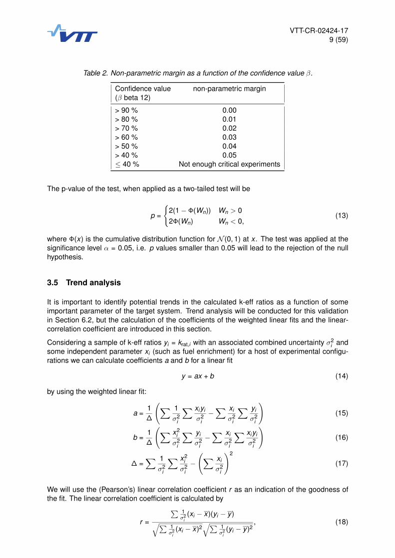
In order to determine the nonparametric margin, the confidence that 95 % of critical experi-ments will produce k-eff values larger than the smallest observed value is calculated with
β = 1 − 0.95N , (12)
where N is the number of critical experiments that have been modelled. Based on the con-fidence value β the nonparametric margin is obtained from Table 2, which is based on therecommendation by the validation methodology guide [1].
3.4 Testing the normality of data
By calculating the k-effective ratios between the calculated and experimental multiplication fac-tors a distribution of krat,i values is obtained. As the single sided lower tolerance limit determinedin this validation is calculated with a 95 % confidence that 95 % of the data lies above the limit,the determination of the limit through statistical means depends on the underlying distributionof the krat,i data. The choice of the statistical treatment depends on whether the krat,i data canbe considered to be normally distributed.
In this validation we use the Shapiro-Wilk test with Royston’s extension described in [3] todetermine, whether the data can be considered to be normally distributed or not. The nullhypothesis of the test is that the calculated krat,i is normally distributed with an unspecifiedmean and variance. The test first calculates the Shapiro-Wilk test statistic W , which is thennormalized to obtain the normalized test statistic Wn. The normalized test statistic is thencompared to the normal distribution with zero mean and unity variance (N (0, 1)).
Table 1. Single-sided lower tolerance factors
Number of experiments U
10 2.91111 2.81512 2.73613 2.67014 2.61415 2.56616 2.52317 2.48618 2.45319 2.42320 2.39621 2.37122 2.35023 2.32924 2.30925 2.29230 2.22035 2.16640 2.12645 2.09250 2.065
VTT-CR-02424-179 (59)
Table 2. Non-parametric margin as a function of the confidence value β.
Confidence value non-parametric margin(β beta 12)
> 90 % 0.00> 80 % 0.01> 70 % 0.02> 60 % 0.03> 50 % 0.04> 40 % 0.05≤ 40 % Not enough critical experiments
The p-value of the test, when applied as a two-tailed test will be
p =
�2(1 − Φ(Wn)) Wn > 02Φ(Wn) Wn < 0,
(13)
where Φ(x) is the cumulative distribution function for N (0, 1) at x . The test was applied at thesignificance level α = 0.05, i.e. p values smaller than 0.05 will lead to the rejection of the nullhypothesis.
3.5 Trend analysis
It is important to identify potential trends in the calculated k-eff ratios as a function of someimportant parameter of the target system. Trend analysis will be conducted for this validationin Section 6.2, but the calculation of the coefficients of the weighted linear fits and the linear-correlation coefficient are introduced in this section.
Considering a sample of k-eff ratios yi = krat,i with an associated combined uncertainty σ2i and
some independent parameter xi (such as fuel enrichment) for a host of experimental configu-rations we can calculate coefficients a and b for a linear fit
y = ax + b (14)
by using the weighted linear fit:
a =1Δ
�� 1σ2
i
� xiyi
σ2i
−� xi
σ2i
� yi
σ2i
�(15)
b =1Δ
�� x2i
σ2i
� yi
σ2i−� xi
σ2i
� xiyi
σ2i
�(16)
Δ =� 1
σ2i
� x2i
σ2i−�� xi
σ2i
�2
(17)
We will use the (Pearson’s) linear correlation coefficient r as an indication of the goodness ofthe fit. The linear correlation coefficient is calculated by
r =
� 1σ2
i(xi − x)(yi − y )
�� 1σ2
i(xi − x)2
�� 1σ2
i(yi − y )2
, (18)

VTT-CR-02424-1710 (59)
where the weighted mean for the independent parameter is
x =
� 1σ2
ixi
� 1σ2
i
(19)
and y is equal to keff from Eq. 5.
The linear correlation coefficient varies between −1 and 1 with large absolute values indicatingstrong linear correlation and values close to zero indicating no significant linear correlation.
VTT-CR-02424-1711 (59)
4. Choosing critical experiments
The choice of the critical experiments for the validation is an essential step of the criticalitysafety validation and needs to be conducted systematically. The overall approach for determin-ing suitable critical experiments and documenting the area of applicability for the validation isdescribed in [1] as follows:
1. Identify the key parameters associated with the nominal and upset conditions of the sys-tem to be evaluated.
2. From the key parameters identified in the first step, establish a "screening" area of appli-cability for identifying potential critical experiments.
3. Identify criticality experiments that are within this screening area of applicability or havethe same key physical parameter.
4. From the scope of selected criticality experiments, determine the detailed area of appli-cability that the experiments cover.
5. Show that the system to be evaluated is within the area of applicability provided by thecritical experiments or provide justification for using the critical experiment parameters forthe system in question.
6. Document the results for the area of applicability.
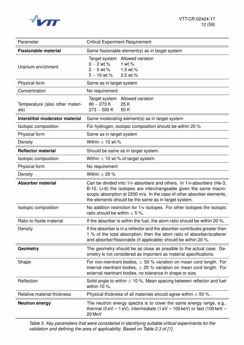
The key parameters to be considered for identifying similarity between the target system andthe critical experiments are listed in Table 3, which is based on Table 2.3 of [1].
4.1 Target application
The target application of this validation were criticality safety analyses considering the Fen-novoima interim spent fuel storage facility as described in [4]. The main characteristics of thestorage geometry used in the criticality safety analyses are described in the following.
The target geometry is shown in Figure 1 as a two dimensional infinite lattice model. Thegeometry consists of an AES-2006 fuel assembly in a storage absorber tube in a repeatedhexagonal lattice. The storage tube is filled with light water and the region between the adjacentstorage tubes is also filled with light water.
We can assess the different key parameters of the target (parameters listed in Table 3) asfollows:
Fissionable material: The fissionable material in the target system is low enriched uraniumdioxide with an enrichment of approximately 5.0 wt.% 235U. The density of the fuel will reflecttypical fuel densities for uranium dioxide fuel pellets. The temperature of the fuel material aswell as other materials will be room temperature.
Moderator material: The moderator material present in the target geometry will be light waterat room temperature and nominal density (approximately 1.0 g/cm3).
Reflector material: The geometry used for the criticality safety analyses is expected to be aninfinite lattice geometry with no notable reflectors. The storage tube functions mainly as a neu-tron absorber and the moderator between the storage tubes functions as a neutron thermaliser,which will increase the absorption of neutrons by the absorber tube. However, the infinite lat-tice cannot be considered as an unreflected system either as the reflectors main purpose is toprevent neutron leakage, which is a non-issue in an infinite lattice geometry.
VTT-CR-02424-1712 (59)
Parameter Critical Experiment Requirement
Fissionable material Same fissionable element(s) as in target system
Uranium enrichment
Target system Allowed variaton0 − 2 wt.% 1 wt.%2 − 5 wt.% 1.5 wt.%5 − 10 wt.% 2.5 wt.%
Physical form Same as in target system
Concentration No requirement
Temperature (also other materi-als)
Target system Allowed variaton80 − 273 K 25 K273 − 500 K 50 K
Interstitial moderator material Same moderating element(s) as in target system
Isotopic composition For hydrogen, isotopic composition should be within 20 %
Physical form Same as in target system
Density Within ± 10 wt.%
Reflector material Should be same as in target system.
Isotopic composition Within ± 10 wt.% of target system.
Physical form No requirement
Density Within ± 25 %
Absorber material Can be divided into 1/v absorbers and others. In 1/v-absorbers (He-3,B-10, Li-6) the isotopes are interchangeable given the same macro-scopic absorption at 2200 m/s. In the case of other absorber elements,the elements should be the same as in target system.
Isotopic composition No addition restriction for 1/v isotopes. For other isotopes the isotopicratio should be within ± 5 %.
Ratio to fissile material If the absorber is within the fuel, the atom ratio should be within 20 %.
Density If the absorber is in a reflector and the absorber contributes greater than1 % of the total absorption, then the atom ratio of absorber/scattererand absorber/fissionable (if applicable) should be within 20 %.
Geometry The geometry should be as close as possible to the actual case. Ge-ometry is not considered as important as material specifications.
Shape For non-reentrant bodies, ± 50 % variation on mean cord length. Forinternal reentrant bodies, ± 25 % variation on mean cord length. Forexternal reentrant bodies, no tolerance in shape or size.
Reflection Solid angle to within ± 10 %. Mean spacing between reflector and fuelwithin 10 %.
Relative material thickness Physical thickness of all materials should agree within ± 50 %.
Neutron energy The neutron energy spectra is to cover the same energy range, e.g.,thermal (0 eV – 1 eV), intermediate (1 eV – 100 keV) or fast (100 keV –20 MeV
Table 3. Key parameters that were considered in identifying suitable critical experiments for thevalidation and defining the area of applicability. Based on Table 2.3 of [1].

VTT-CR-02424-1713 (59)
Figure 1. Geometry plot from the unit cell of the target geometry (infinite lattice 2 dimensionalmodel). Yellow corresponds to fuel, blue to water, black to void regions, green to absorber tubeand grey to cladding, guide tube and instrumentation tube materials.
Absorber material: The hexagonal storage tube surrounding the assembly consists of bo-rated steel (boron content approximately 1.5 wt.%). The boron is expected to have a naturalisotopic composition (80.1 at.% of 10B and 19.9 at.% of 11B).
Geometry: The unit cell of the target geometry consists of fuel rods in an assembly (hexag-onal lattice) surrounded by an absorber tube and water. The hexagonal pitch in the fuel pinlattice is 1.275 cm. The assembly separation is approximately 30 cm. The fuel pellet inner andouter radii are 0.06 and 0.38 cm respectively.
Neutron energy: The target system is a thermal system. To measure the moderation in thetarget system, the energy corresponding to the average lethargy of neutrons causing fission(EALF) was calculated for the nominal conditions of the target geometry (Appendix 2 of ref-erence [4]) with Serpent 2.1.28 using ENDF/B-VII based cross sections. The obtained EALFvalue was 0.35 eV.
4.2 General parameters for choosing critical experiments
Based on the parameters of the target system, general screening parameters for choosingcritical experiments were derived:
Fissionable material: The fissionable material should be uranium dioxide with an enrichmentin the range of 3.5 wt.% to 7.5 wt.% 235U. The density of the fuel should reflect typical fueldensities for uranium dioxide fuel pellets. The temperature of the fuel material as well as othermaterials should be room temperature.
VTT-CR-02424-1714 (59)
Moderator material: The moderator material should be light water at room temperature andnominal density (approximately 1.0 g/cm3).
Reflector material: As the target system is neither reflected nor unreflected, there are nostrict demands for the reflector material. As the gaps between the assemblies in the targetsystem contain water and stainless steel, water and stainless steel reflectors would be preferredin the experiments.
Absorber material: The absorber material should be natural boron. Borated steel with boroncontent close to the target system is the preferred absorber material, but other borated materi-als may also be considered.
Geometry: The geometry should consist of fuel rods arranged in a lattice with interstitialwater moderator. Geometries with a similar pin lattice as in the target system (hexagonal,similar pitch) should be favored. Other geometrical similarities to the target system should alsobe considered.
Neutron energy: Only thermal systems should be considered.
These screening parameters are collected into Table 4 for quick reference.
4.3 Experiments from existing collection
The first considered source for critical experiments was the library of inputs contained in thecriticality safety validation package (CSVP) collected at VTT during the previous years [5]. Allof the inputs found in this validation package have been created based on critical benchmarkexperiments taken from the International Handbook of Evaluated Criticality Safety BenchmarkExperiments [6] later referred to as the Handbook. As of the beginning of 2017, the validationpackage contained 234 inputs from six experimental series. The suitability of the various ex-periments for inclusion in this validation is evaluated in the following based on the screeningparameters listed in Table 4.
All of the experimental series were from the LEU-COMP-THERM (LCT) part of the Handbook,which contains experiments using low-enriched uranium (LEU) in compound form (COMP) inthermal arrangements (THERM). As all of the experiments were from the thermal part of thehandbook they fulfill the neutron energy screening parameter.
LCT-015
The title of the benchmark description was The VVER Experiments: Regular and PerturbedHexagonal Lattices of Low-Enriched UO2 Fuel Rods in Light Water.
This experimental series contained 165 critical or near-critical experiments of which 151 criticalexperiments have been modelled in the CSVP. The experimental program focused on experi-ments relevant to VVER-440 and VVER-1000 reactor types. The experiments contained regularor perturbed fuel rod configurations in hexagonal lattice geometry with variable pitch. The ex-periments were conducted in a water pool or tank, where criticality was achieved by adjustingthe water level.
Fissionable material: The fuel material was 1.6, 3.6 or 4.4 wt.% enriched UO2.
Moderator: The moderator was light water with or without boric acid,
Reflector: The experimental configurations were surrounded by water.

VTT-CR-02424-1715 (59)
Parameter Target system Critical experiments
Fissionable material Uranium with 235U as themain fissioning isotope.
Same as in target.
Uranium enrichment 5.0 wt.% 3.5 – 7.5 wt.%
Physical form Uranium dioxide Same as in target.
Concentration Density as fabricated Density as fabricated
Temperature (also other materi-als)
Room temperature Room temperature
Interstitial moderator material Light water Light water
Isotopic composition Light water Light water
Physical form Liquid Liquid
Density 1.0 g/cm3 0.9–1.1 g/cm3
Reflector material Not applicable Water, steel.
Absorber material Borated steel Materials with natural boronabsorber.
Isotopic composition Natural boron Natural boron
Ratio to fissile material Absorber not within fuel N/A
Density Absorber not within reflector N/A
Geometry Fuel pins in hexagonal as-sembly surrounded by stor-age tube of borated steel. In-finite lattice.
Fuel pins in lattice geome-tries. Preferably with ab-sorber plates.
Shape Mainly significant for deter-ministic solvers
Normal lattice geometry.
Reflection Infinite lattice N/A
Relative material thickness Fuel rod geometry. Similar fuel rod geometry ifpossible.
Neutron energy Thermal system (0.35 eVEALF)
Thermal system
Table 4. Screening parameters that were considered in identifying suitable critical experimentsfor the validation and defining the area of applicability. Based on Table 2.3 of [1].
VTT-CR-02424-1716 (59)
Absorber: The moderator contained boron (boric acid) as an absorber in a number of theexperiments and additional absorber rods of borated zirconium, Boral, boron carbide and Eu-ropium oxide were used in a number of experiments.
Geometry: The geometry was fuel pins in a hexagonal lattice (1.1–1.9 cm pitch). The fuel rodgeometry was reasonably similar to the one in the target system with the same outer radius ofthe fuel pellet but no central hole in the pellet.
The experiments with 1.6 wt. % enriched fuel were excluded based on the screening param-eters. All experiments without boron absorber were excluded based on the screening param-eters. The experiments with the Europium absorber were excluded based on the screeningparameters.
In order to limit the number of cases from a single benchmark only 16 cases were included fromLCT-015. All of the included cases contained boric acid in the moderator, no absorber rods anda fuel enrichment of 3.6 or 4.4 wt. %.
LCT-034
The title of the benchmark description was Four 4.738-wt.%-enriched uranium dioxide rodassemblies contained in cadmium, borated stainless steel, or boral square canisters, water-moderated and -reflected
The benchmark description contained 24 experiments with four fuel assemblies surrounded byabsorber plates in a water tank, where criticality was achieved by adjusting the water level inthe tank.
Fissionable material: The fuel material was 4.738 wt.% enriched UO2.
Moderator: The moderator was light water without additives.
Reflector: The four assemblies were surrounded with a water reflector from sides and bottom.
Absorber: All of the experiments used absorbing plates of borated steel (1.1 wt.% boron),Boral or cadmium.
Geometry: The geometry was fuel pins in assemblies (square lattice 1.6 cm pitch) surroundedby absorber plates.
The fissionable material, moderator and reflector fulfilled the screening parameters for all ex-periments. The lattice geometry of the experiment was different from the target system (squarelattice with larger pitch), but as Monte Carlo codes use the same solution routines for squareand hexagonal lattices, this was not seen to warrant the exclusion of the experimental series.The 10 experiments with cadmium absorber were not included.
The 14 experiments with borated steel or Boral absorber plates were included in this validation.
LCT-040
The title of the benchmark description was Four 4.738-wt.%-enriched uranium dioxide rod as-semblies contained in borated stainless steel or boral square canisters, water moderated andreflected by lead or steel
The benchmark description contained 10 experiments with four fuel assemblies surrounded byabsorber plates and lead or steel reflector blocks in a water tank, where criticality was achievedby adjusting the water level in the tank.

VTT-CR-02424-1717 (59)
Fissionable material: The fuel material was 4.738 wt.% enriched UO2.
Moderator: The moderator was light water without additives.
Reflector: The four assemblies were surrounded with a lead or stainless steel reflector fromsides and a water reflector from bottom.
Absorber: All of the experiments used absorbing plates of borated steel (1.1 wt.% boron) orBoral.
Geometry: The geometry was fuel pins in assemblies (square lattice 1.6 cm pitch) surroundedby absorber plates and reflector blocks.
The fissionable material, moderator and absorber fulfilled the screening parameters for all ex-periments. The lattice geometry of the experiment was same as in LCT-034 and while beingdifferent from the target system was not seen to warrant the exclusion of the experimental se-ries. The system was reflected with lead or stainless steel in this setup instead of water as inLCT-034. As the reflector material was not a key parameter in the target system, this was notseen to warrant the exclusion of the experimental series.
All 10 experiments were included in this validation.
LCT-053
The title of the benchmark description was VVER physics experiments: regular hexagonal (1.27cm pitch) lattices of low-enriched U(4.4 wt.% 235U)O2 fuel rods in light water at different corecritical dimensions
The benchmark description contained 14 experiments with a variable number of fuel rods in ahexagonal lattice in a roughly circular shape. The experiments were conducted in a water tank,where criticality was achieved by adjusting the water level in the tank.
Fissionable material: The fuel material was 4.4 wt.% enriched UO2.
Moderator: The moderator was light water without additives.
Reflector: The core formed by the fuel rods was surrounded with a water reflector from sidesand bottom.
Absorber: None of the experiments contained neutron absorbers.
Geometry: The geometry was fuel pins in a hexagonal lattice with 1.27 cm pitch in a roughlycircular shape.
As none of the experiments contained boron absorber, which was a key component of the targetsystem, none of the experiments were included in this validation.
LCT-086
The title of the benchmark description was VVER physics experiments: hexagonal lattices(1.275 cm pitch) of low-enriched U(3.6, 4.4 WT.% 235U)O2 fuel assemblies in light water withH3BO3.
The benchmark description contained ten experiments with seven short VVER-1000 type fuelassemblies in a hexagonal configuration. The experiments were conducted in a water pool,where criticality was achieved by adjusting the water level in the pool.
VTT-CR-02424-1718 (59)
Fissionable material: The fuel material of all assemblies was UO2. The six driver assemblieshad an enrichment of 3.6 or 4.4 wt.% and the enrichment of the central fuel assembly variedfrom 2.0 to 4.4 wt.%.
Moderator: The moderator was light water with boric acid.
Reflector: The core formed by the fuel assemblies was surrounded with a water reflector fromsides and bottom.
Absorber: All of the experiments contained soluble boron absorber in the moderator.
Geometry: The fuel assemblies (hexagonal lattice 1.275 cm pitch) formed a hexagonal shape,where six driver assemblies surrounded a central assembly.
The fissionable material, moderator and reflector fulfilled the screening parameters. The neu-tron absorber in the experiments was not contained in plates but soluble in the moderator. Theassembly geometry was notably similar to the target system.
The boron absorber was situated in the moderator rather than in plates as in the target system.However there is no restriction concerning the physical form of the absorber material (Ref. [1]Tbl 2.3). The assembly geometry was notably similar to the target system.
All of the 10 experiments were included in the validation.
LCT-087
The title of the benchmark description was VVER physics experiments: hexagonal lattices(1.22-cm pitch) of low-enriched U(3.6, 4.4 WT.% U235)O2 fuel assemblies in light water withvariable fuel-assembly pitch.
The benchmark description contained 25 experiments with 19 short VVER-440 type fuel as-semblies in a hexagonal lattice configuration. The central assembly was surrounded by anabsorber tube in some of the experiments. The experiments were conducted in a water pool,where criticality was achieved by adjusting the water level in the pool.
Fissionable material: The fuel material of the surrounding 18 fuel assemblies was 3.6 wt.%enriched UO2. The fuel material of the central fuel assembly was either 3.6 or 4.4 wt.% enrichedUO2.
Moderator: The moderator was light water without additives.
Reflector: The core formed by the fuel assemblies was surrounded with a water reflector fromsides and bottom.
Absorber: Some of the experiments contained an absorber tube (borated steel or iron with asmall amount of boron).
Geometry: The fuel assemblies (hexagonal lattice 1.22 cm pitch) were situated in a hexagonallattice with a variable pitch.
The fissionable material, moderator, reflector and geometry fulfilled the screening parametersfor all experiments. Boron absorber was present only in part of the experiments, with the ab-sorber being incorporated either in borated steel (0.76 or 1.04 wt.% boron) or an iron absorber(0.012 wt.% boron). The experiments with the iron absorber were excluded due to the lowboron content of the absorber. The experiments with no absorber tube were also excluded.
The 7 experiments with borated steel absorbers were included in the validation.

VTT-CR-02424-1719 (59)
4.4 Additional experiments
57 critical experiments fitting the screening criteria were identified from the existing criticalitysafety validation package. 19 experiments contained borated steel absorbers, 12 contained Bo-ral plate absorbers and 26 contained boric acid in the moderator. In order to identify additionalexperiments with borated steel plate absorbers (similar to the target system), the Database forthe International Criticality Safety Benchmark Evaluation Project (DICE) was searched with thefollowing parameters:
������� �������� � ��� �������� �������
��� �������� ���� � ��������
��� �������� � �������
��� ���������� � ����������
��� ������� �������� � ������� �����
��� � ������� � ����
��� ������ ������� �� � ������� �� ��� ��� �� ���
��� ����������������� �������� � ����� ������ ������
��� ����� � ������� ��������� ����� ��� ��� ��� ���
Three additional experimental series were identified with borated steel plates (LCT-009, LCT-013 and LCT-089).
The largest fuel enrichments in the included experiments and the additional experimental serieswere still below the target systems 5.0 wt.%. The included experiments should cover the targetsystem from both sides so that any trends in the bias of the code system can be interpolated,rather than extrapolated, for the enrichment in the target system. This meant that additionalexperimental series with boron absorber and a higher fuel enrichment were required. A searchwith a fuel enrichment between 5.0 and 7.5 wt.% and any solid borated materials as neutronabsorber resulted in two potential experimental series (LCT-075 and LCT-076). A search witha fuel enrichment between 5.0 and 7.5 wt.% and soluble boron in light water resulted in onepotential experimental series (LCT-021).
All of the identified potential additional experimental series are evaluated against the screen-ing parameters in the following. As all of the experiments were from the thermal part of thehandbook they fulfill the neutron energy screening parameter.
LCT-009
The title of the benchmark description was water-moderated rectangular clusters of U(4.31)O2fuel rods (2.54-cm pitch) separated by steel, Boral, copper, cadmium, aluminium or Zircaloy-4plates
The benchmark description contained 27 experiments in which rectangular clusters of fuel rodswere separated by two absorbing or non-absorbing plates. The experiments were conducted ina water pool, where criticality was achieved by adjusting the separation of the fuel rod clusters.
Fissionable material: The fuel material was 4.31 wt.% enriched UO2.
Moderator: The moderator was light water without additives.
Reflector: The three fuel rod clusters were surrounded with a water reflector from sides andtop. The bottom reflector consisted of an acrylic support plate followed by water.
Absorber: All of the experiments contained separating plates, some of which contained ab-sorbers. Four experiments used borated steel plates, one experiment used Boral plates, ten

VTT-CR-02424-1720 (59)
experiments used cadmium containing absorber plates and the rest of the experiments wereconducted with plates that contained no notable concentrations of absorbers.
Geometry: The fuel clusters (15 by 8 rod square lattice 2.54 cm pitch) were situated in 3 by 1cluster arrangement with a variable distance between the central cluster and the side clusters.The absorber plates were situated in the water gaps between the central cluster and the sideclusters.
The fissionable material, moderator and reflector fulfilled the screening parameters for all ex-periments. Boron absorber was present only in part of the experiments, with the boron absorberbeing incorporated either in borated steel (1.1 or 1.67 wt.% boron) or Boral. The experimentswithout boron absorber were excluded. The pin-lattice geometry had a larger pitch than in thetarget system, but the aspect of "assemblies" separated with water and absorber plate wassimilar to the target system. Overall the geometry was judged to be similar enough to the targetsystem not to warrant exclusion of the experimental series.
The 5 experiments containing borated steel or Boral absorber plates were included in the vali-dation.
LCT-013
The title of the benchmark description was Water-moderated rectangular clusters of U(4.31)O2fuel rods (1.892-cm pitch) separated by steel, Boral, Boroflex, cadmium, or copper plates, withsteel reflecting walls.
The experiments included in this benchmark are quite similar to those included in LCT-009.However, in this case stainless steel reflecting walls surrounded the clusters on two sides withtwo sides being still reflected by water. The central fuel cluster was again separated from theother two clusters with water and absorbing or non-absorbing plates.
Fissionable material: The fuel material was 4.31 wt.% enriched UO2.
Moderator: The moderator was light water without additives.
Reflector: The three fuel rod clusters were surrounded with a water reflector from two sidesand top. The reflector on two sides was stainless steel. The bottom reflector consisted of anacrylic support plate followed by water.
Absorber: All of the experiments contained separating plates, some of which contained ab-sorbers. One experiments used borated steel plates, one experiment used Boral plates, one ex-periment used Boroflex plates and two experiments used cadmium containing absorber plates.The rest of the experiments were conducted with plates that contained no notable concentra-tions of absorbers.
Geometry: The fuel clusters (12 by 16 rod square lattice 1.892 cm pitch) were situated in 3 by1 cluster arrangement with a variable distance between the central cluster and the side clusters.The absorber plates were situated in the water gaps between the central cluster and the sideclusters.
The fissionable material, moderator and reflector fulfilled the screening parameters for all ex-periments. Boron absorber was present only in part of the experiments, with the boron absorberbeing incorporated either in borated steel (1.1 wt.% boron), Boral or Boroflex. The experimentswithout boron absorber were excluded. The pin-lattice geometry had a larger pitch than in thetarget system, but the aspect of "assemblies" separated with water and absorber plate wassimilar to the target system. As in LCT-009, the geometry was judged to be similar enough tothe target system not to warrant exclusion of the experimental series.

VTT-CR-02424-1721 (59)
The 3 experiments containing borated steel, Boral or Boroflex absorber plates were included inthe validation.
LCT-021
The title of the benchmark description was Hexagonally pitched partially flooded lattices ofU(5%)O2 zirconium clad fuel rods moderated by water with boric acid.
The benchmark description contained 6 experiments with a variable number of fuel rods in ahexagonal lattice in a roughly circular shape. The experiments were conducted in a water pool,where criticality was achieved by adjusting the water level in the pool.
Fissionable material: The fuel material was 5.0 wt.% enriched UO2.
Moderator: The moderator was light water with boric acid.
Reflector: The core formed by the fuel rods was surrounded with a water reflector from sidesand bottom.
Absorber: All of the experiments contained soluble boron absorber in the moderator.
Geometry: The geometry was fuel pins in a hexagonal lattice with 1.0 or 1.3 cm pitch in aroughly circular shape.
The fissionable material, moderator and reflector fulfilled the screening parameters for all ex-periments. In these experiments, the boron absorber was present in the moderator rather thanin solid structures, which is a minor issue in the benchmark. The geometry did not contain fuelassemblies or assembly imitators but the hexagonal lattice pitch was similar to the one in thetarget system.
As there is no restriction concerning the physical form of the absorber material (Ref. [1] Tbl2.3) and the other key parameters were fulfilled well, all 6 experiments were included in thevalidation.
LCT-075
The title of the benchmark description was VVER physics experiments: hexagonal (1.10 cmpitch) lattices of low-enriched U(6.5 WT.% 235U)O2 fuel rods in light water, perturbed by boronabsorber rods and water holes.
The benchmark description contained 6 experiments with VVER-type fuel rods in a hexagonallattice forming a core with a roughly circular shape. The regular lattice was perturbed either bywater holes or boron carbide absorber rods. The experiments were conducted in a water pool,where criticality was achieved by adjusting the water level in the pool.
Fissionable material: The fuel material was 6.5 wt.% enriched UO2.
Moderator: The moderator was light water without additives.
Reflector: The core formed by the fuel rods was surrounded with a water reflector from sidesand bottom.
Absorber: Three of the experiments contained six boron carbide absorber rods in the core.
Geometry: The geometry was fuel pins in a hexagonal lattice with 1.1 cm pitch in a roughlycircular shape.

VTT-CR-02424-1722 (59)
The fissionable material, moderator and reflector fulfilled the screening parameters for all exper-iments. The geometry did not contain fuel assemblies or assembly imitators but the hexagonallattice pitch was reasonably close to the one in the target system. Three of the experimentscontained no neutron absorber and were excluded. The other three experiments containedboron absorber in a small number of boron carbide rods.
The 3 experiments containing boron carbide rods were included in the validation.
LCT-076
The title of the benchmark description was Light water moderated and reflected low enricheduranium (3 wt.% 235U) dioxide rod lattices with ex-core detector feature
The benchmark description contained 7 experiments that simulated a system of 12 PWR fuelassemblies at the periphery of a PWR core. The fuel assemblies were arranged into a cruciformshape. The experiments were conducted in a water tank, where criticality was achieved byadjusting the water level in the tank.
Fissionable material: The fuel was mostly 3.0 wt.% enriched UO2 with three experimentsusing a number of fuel rods with 7.0 wt.% enriched UO2.
Moderator: The moderator was light water without additives.
Reflector: The cruciform core was surrounded by a stainless steel baffle surrounded by water.
Absorber: Three experiments used 12 or 16 burnable absorber rods consisting of thick-walledhollow borosilicate glass cylinders.
Geometry: The fuel rods were arranged in a cruciform shape using a square lattice geometrywith 1.2507 cm pitch.
Only one of the experiments (S06D/6) contained both 7.0 wt.% enriched fuel rods and boronabsorbers. In this experiment the high enriched fuel rods made up less than ten percent of allfuel rods, the others being 3.0 wt.% enriched UO2.
Due to the majority of fuel being of enrichment that is outside of the screening area, no experi-ments were included from this benchmark.
LCT-089
The title of the benchmark description was Critical loading configurations of the IPEN/MB-01reactor with UO2 and borated stainless steel plates.
The benchmark description contained 4 experiments, in which borated steel plates were in-serted into a fuel rod lattice (core of the IPEN/MB-01 reactor) in different geometric configu-rations. The experiments were conducted in a water pool, where criticality was achieved bymodifying the water temperature.
Fissionable material: The fuel was 4.34 wt.% enriched UO2.
Moderator: The moderator was light water without additives.
Reflector: The core was surrounded by light water.
Absorber: All of the experiments contained two borated steel plates (1.787 wt.% boron) insidethe fuel lattice. Additionally, the Ag-In-Cd (AIC) control rods situated in two quarters of the core
VTT-CR-02424-1723 (59)
were withdrawn from the active core, but their lower ends were still situated close to the top ofthe active core.
Geometry: The fuel rods were arranged in a square shape using a square lattice geometrywith 1.5 cm pitch.
The fissionable material, moderator and reflector fulfilled the screening parameters for all ex-periments. The geometry did not contain fuel assemblies or assembly imitators and the squarelattice pitch was larger the hexagonal pitch in the target system. The geometry did containborated steel plates interacting with a fuel rod lattice similar to the lattice system. All of the ex-periments contained boron absorber in borated steel plates quite similar to the target system.The small effect of the AIC control rods on the neutron absorption near the top of the activecore in two of the four quadrants was not seen to warrant the exclusion of the experimentalseries from the validation.
All 4 cases were included in the validation.
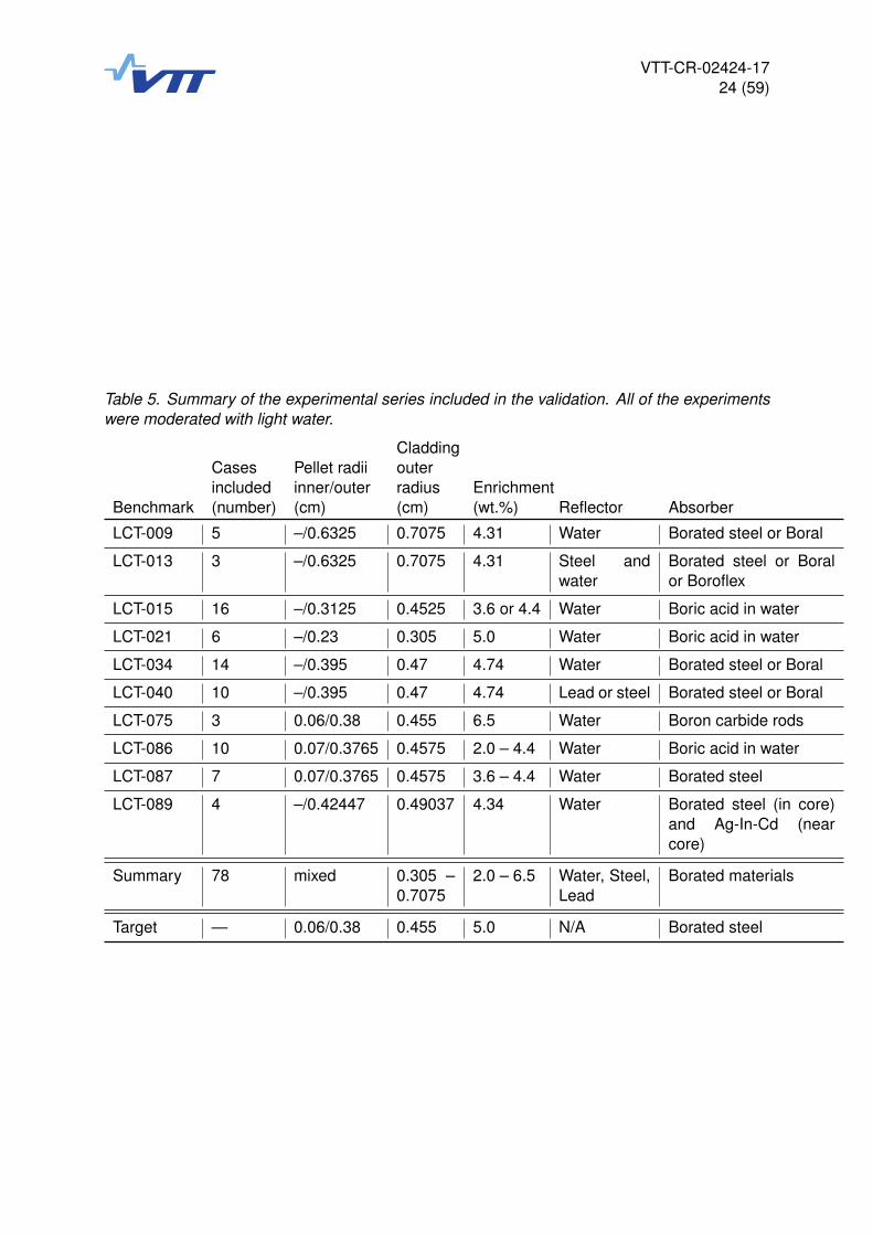
4.5 Summary of experiments included in the validation
The complete list of experiments included in the validation is given in Appendix A. The includedexperiments are summarized in Table 5 on benchmark level. The fuel enrichment of the tar-get system (5.0 wt.%) is covered by the experiments, although only 9 experiments have fuelenrichments equal to or larger than the target system. However, 24 experiments have a fuelenrichment of 4.74 wt.% which is close to the target system. The enrichments in the otherexperiments are within the allowed range for variation (see Tbl. 3)3.
All of the experiments used a light water moderator in room temperature like the target system.The target system was an infinite lattice system meaning that the neutron reflective propertiesof the included materials have a reduced impact on the multiplication factor. The experimentswere finite systems with water, lead or stainless steel reflectors.
The absorber in the target system was natural (i.e. non-isotope enriched) boron in boratedsteel plates surrounding the fuel assemblies. All of the included experiments included naturalboron absorbers: 28 experiments contained borated steel plates. 14 experiments containedBoral plates. 1 experiment contained Boroflex plates. 3 experiments contained boron carbideabsorber rods. 32 experiments contained boric acid in the moderator. Although not all of theexperiments contained borated steel plates like the target system, the collection of experimentsshould cover any biases resulting from the modelling of Boron absorbers (e.g. from uncertain-ties in the boron cross section data).
The key parameters of the target system are covered by the chosen experiments. The exactlevel of moderation in the experiments compared to the target system is estimated by calculat-ing the energy corresponding to the average lethargy of neutrons causing fission (EALF) andcomparing this value to the one obtained for the target system. This is done during the trendanalyses in Section 6.2.
3In experiments 5 and 10 of the experimental series LCT-086 one of the fuel assemblies had a low enrichment of2.0 %. However the driver fuel assemblies consisted of 4.4 % (case 5) or 3.6 % (case 10) enriched uranium oxide.
VTT-CR-02424-1724 (59)
Table 5. Summary of the experimental series included in the validation. All of the experimentswere moderated with light water.
CladdingCases Pellet radii outerincluded inner/outer radius Enrichment
Benchmark (number) (cm) (cm) (wt.%) Reflector Absorber
LCT-009 5 –/0.6325 0.7075 4.31 Water Borated steel or Boral
LCT-013 3 –/0.6325 0.7075 4.31 Steel andwater
Borated steel or Boralor Boroflex
LCT-015 16 –/0.3125 0.4525 3.6 or 4.4 Water Boric acid in water
LCT-021 6 –/0.23 0.305 5.0 Water Boric acid in water
LCT-034 14 –/0.395 0.47 4.74 Water Borated steel or Boral
LCT-040 10 –/0.395 0.47 4.74 Lead or steel Borated steel or Boral
LCT-075 3 0.06/0.38 0.455 6.5 Water Boron carbide rods
LCT-086 10 0.07/0.3765 0.4575 2.0 – 4.4 Water Boric acid in water
LCT-087 7 0.07/0.3765 0.4575 3.6 – 4.4 Water Borated steel
LCT-089 4 –/0.42447 0.49037 4.34 Water Borated steel (in core)and Ag-In-Cd (nearcore)
Summary 78 mixed 0.305 –0.7075
2.0 – 6.5 Water, Steel,Lead
Borated materials
Target — 0.06/0.38 0.455 5.0 N/A Borated steel
VTT-CR-02424-1725 (59)
5. Running calculations
The calculations were executed in the potku2 cluster of VTT (������������������) using a perlscript to create the inputs, run the calculations and collect the simulation results.

VTT-CR-02424-1726 (59)
6. Analysis of the results
The experiment-by-experiment results of each code version are collected in Appendices B–D.Table 6 shows the basic sample statistics derived from the calculation results of each codeversion. The values are rounded for presentation in the table, but unrounded values were usedto calculate the further derived parameters. The weighted mean of the k-eff ratios is greaterthan unity for all of the code versions. Overall, the statistics are very close to each otherbetween the code versions suggesting that there are no notable differences in the applicabilityof the versions to criticality safety calculations.
Table 6. Basic sample statistics derived from the calculation results for each code version.
Statistical How calculated? Serpent 2.1.25 Serpent 2.1.27 Serpent 2.1.28variable
keff Eq. 5 1.00287 1.00293 1.00292σ2 Eq. 7 5.861 × 10⁻⁶ 5.862 × 10⁻⁶ 5.863 × 10⁻⁶
σ Square root of previous 0.002 42 0.002 42 0.002 42s2 Eq. 8 1.556 × 10⁻⁵ 1.525 × 10⁻⁵ 1.541 × 10⁻⁵
s Square root of previous 0.003 94 0.003 91 0.003 93S2
P Eq. 9 2.141 × 10⁻⁵ 2.112 × 10⁻⁵ 2.128 × 10⁻⁵
SP Square root of previous 0.004 63 0.004 60 0.004 61
The results from the normality test applied to the k-eff ratio distributions are collected in Table 7.The k-eff ratio distribution for each code version can be considered to be normal at the chosensignificance level of α = 0.05. The single sided tolerance limit will therefore be calculated usingEq. 10.
Table 7. The results of the normality test applied to the results of the validation calculations.
Statistical variable How calculated? Serpent 2.1.25 Serpent 2.1.27 Serpent 2.1.28
W test parameter Ref. [3] 0.971 270 0.971 117 0.971 390Wn normalized test parameter Ref. [3] 1.440 367 1.451 980 1.431 224p-value for Wn Eq. 13 0.149 764 0.146 508 0.152 366Considered normal p > α? Yes. Yes. Yes.
6.1 Single sided tolerance limit
As the weighted mean of the k-eff ratios exceeded unity for all of the code versions the lowervariant of Eq. 10 was used to calculate the single sided tolerance limit KL. This means that theKL were calculated by
KL = 1.0 − USP (20)
The parameter U was looked up from Table 1 based on the number of modelled experiments,which was 78. As the number of experiments exceeded the maximum tabulated value (50),the value of U corresponding to the maximum tabulated value was used (U = 2.065) as aconservative number as suggested in [1].

VTT-CR-02424-1727 (59)
Table 8. The single sided tolerance limits (KL) calculated for the different code versions basedon the results of the validation calculations.
Statistical How calculated? Serpent 2.1.25 Serpent 2.1.27 Serpent 2.1.28variable
KL Eq. 20 0.990 444 0.990 511 0.990 475
The single sided tolerance limits were calculated for the three code versions using U equalto 2.065 and non-rounded values for the square root of the pooled variance SP . The calcu-lated values are tabulated in Table 8. The calculated single sided tolerance limits are used inSection 7 for the calculation of the upper safety limits.
6.2 Trend analyses
Identifying potential trends in the calculated k-eff ratios with respect to one of the importantparameters in the experiments (enrichment, lattice pitch etc.) is an important part of the valida-tion. This helps in either choosing the methodology for calculating the upper safety limit or inlimiting the area of the applicability of the validation.
As the single sided tolerance limit was calculated based on the fact that the weighted mean ofthe k-effective ratio is larger than 1.0 we shall limit the area of applicability of this validation tothe regions of the parameters, where the trends predict k-effective ratios larger than 1.0. Analternative approach would be to use the linear weighted tolerance band approach (describedin [1]) for calculating a lower value for KL based on the linear fit at the regions where the fitpredicts k-effective ratios less than 1.0.
This idea is best illustrated visually. Figure 2 contains the calculated k-effective ratios as afunction of fuel enrichment for Serpent 2.1.25. A weighted linear fit has been calculated basedon the data and plotted in the figure with a black line. The Pearson linear-correlation coefficientfor the fit is −0.274. Based on this coefficient and visual inspection of the data a linear correla-tion between the two variables (fuel enrichment and k-eff ratio) seems plausible. Based on thefit, fuel enrichments larger than 6.31 wt.% will produce (statistically speaking) k-effective ratiosless than 1.0. This area is marked into the figure with a red tint in the background.
In order to provide a constant upper safety limit for easy application with a reduced risk ofmisuse, we shall exclude these "red tinted regions" from the area of the applicability.
The following parameters were considered in the trend analysis:
• Fuel enrichment. The value for the target system was 5.0 wt.%. The experiments con-taining multiple fuel enrichments in the same core were excluded from the trend analysis.
• The macroscopic absorption cross section of boron (sum of both isotopes) at 2200 m/sneutron energy in the boron containing material, which can be considered the "blackness"of the neutron absorbing material. The value for the target system was 4.92 1/cm.
• Pin pitch, which will affect the moderation in the fuel lattice. The value for the target sys-tem was 1.275 cm. Only experiments with hexagonal pin lattice geometry were includedin the trend analysis.
• The energy corresponding to the average lethargy of neutrons that cause fission (EALF),which measures the fission inducing neutron energy spectrum in the system. The valuefor the target system was 0.35 eV.

VTT-CR-02424-1728 (59)
3.5 4.0 4.5 5.0 5.5 6.0 6.5Enrichment (wt.%)
0.94
0.95
0.96
0.97
0.98
0.99
1.00
1.01
1.02
k cal
c/k e
xp
LCT-009LCT-013
LCT-015LCT-021
LCT-034LCT-040
LCT-075LCT-086
LCT-087LCT-089
Linear fitKL
USL2USL1
Figure 2. Trend analysis for a linear trend of k-effective ratio versus fuel enrichment for Serpent2.1.25. The enrichment of the target system is indicated with a vertical grey line. The regionwhere the linear fit predicts k-effective ratios below 1.0 is shown with red tinted background. Thetwo upper safety limits calculated based on KL are also shown: USL1 for normal conditions andanticipated operational occurrences and USL2 for other design basis scenarios.
The data for these four parameters in each experiment are given in Table H.1. The fuel en-richment and lattice pitch were obtained directly from the benchmark descriptions. The macro-scopic absorption cross section of boron was calculated by taking the microscopic total ab-sorption cross section of each isotope at 0.0253 eV (2200 m/s) from the cross section data,multiplying the cross sections with the atomic densities of each boron isotope in the boron con-taining material and summing up the two isotope-wise macroscopic absorption cross sections.The EALF values were calculated with Serpent 2.1.28 for each of the experiments using thesame cross section library that was used in this validation.
The calculated coefficients for the weighted linear fits for each code version are listed in Ta-bles 9–11. The differences in the fits between the code versions were small. Based on thelinear-correlation coefficients r and visual inspection of the data (presented in Appendices E–G), the trends with respect to fuel enrichment and pin pitch were considered to be plausibletrends and were treated as such. However, including the boron macroscopic cross section andthe EALF to the plausible trends would not have resulted in further limitations to the area ofapplicability.
The limitations by the linear trends to the area of applicability are given in Table 12 for thetwo parameters and the different code versions. These limitations are used in Section 8 inconjunction with other data to define the area of applicability for this validation.

VTT-CR-02424-1729 (59)
Table 9. Linear correlation coefficients for the linear fits (y = ax +b) against different parametersfor Serpent 2.1.25.
a b r correlated?
Enrichment -0.001262 1.008188 -0.233 YesBoron Σc -0.000044 1.003305 -0.180 NoPin pitch 0.020970 0.980503 0.455 YesEALF 0.002163 1.002175 0.197 No
Table 10. Linear correlation coefficients for the linear fits (y = ax + b) against different parame-ters for Serpent 2.1.27.
a b r correlated?
Enrichment -0.001283 1.008334 -0.240 YesBoron Σc -0.000045 1.003374 -0.186 NoPin pitch 0.020935 0.980543 0.454 YesEALF 0.002058 1.002266 0.189 No
Table 11. Linear correlation coefficients for the linear fits (y = ax + b) against different parame-ters for Serpent 2.1.28.
a b r correlated?
Enrichment -0.001267 1.008258 -0.235 YesBoron Σc -0.000044 1.003355 -0.180 NoPin pitch 0.020724 0.980834 0.449 YesEALF 0.002165 1.002223 0.198 No
Table 12. Limitations to the area of applicability resulting from the trend analysis.
Serpent 2.1.25 Serpent 2.1.27 Serpent 2.1.28
Enrichment (maximum) 6.48 wt.% 6.49 wt.% 6.51 wt.%Pin pitch (minimum) 0.93 cm 0.93 cm 0.93 cm
VTT-CR-02424-1730 (59)
7. Determining safety limits
The upper safety limits are determined based on the single sided tolerance limits listed inTable 8 using Eq. 1. For analyses conducted for systems within the area of applicability (AoA)for this validation (see next section for determination of the AoA), the margin for extension ofthe area of applicability (ΔAoA) is set to zero. The formula used for calculating the upper safetylimits is then
USL = KL −ΔSM, (21)
where ΔSM is the safety margin as was described in Section 3.1. To reiterate, two separatesafety limits are given in the Finnish Regulatory Guides on nuclear safety that correspond totwo separate safety margins. The first margin ΔL1
SM is equal to 0.05 and is applied to normalconditions and anticipated operational occurrences. The second margin ΔL2
SM is equal to 0.02and is applied to other design basis scenarios. The single sided tolerance limits calculated inSection 6.1 were rounded down4 to the fifth significant digit and the two safety margins weresubtracted to obtain the upper safety limits listed in Table 13.
Table 13. Upper Safety Limits determined for the three code versions included in the validation.
Limit Applied to Serpent 2.1.25 Serpent 2.1.27 Serpent 2.1.28
USL1 Normal conditions and an-ticipated operational occur-rences
0.94044 0.94051 0.94047
USL2 Other design basis scenarios 0.97044 0.97051 0.97047
The upper safety limits shall be applied for future criticality safety calculation so that systemsfor which the calculated multiplication factor kcalc. fulfills
kcalc. + 2σcalc. < USL. (22)
can be considered to fulfill the requirement of subcriticality. σcalc. is the statistical uncertainty ofthe calculated multiplication factor.
In applications that cannot be considered to lie in the area of applicability for this validation, afurther margin for subcriticality ΔAoA needs to be subtracted from the upper safety limits listedin Table 13. The margin should be based on the results of the sensitivity study (bias trends) aswell as engineering judgement [1].
4Rounding down results in a stricter safety limit and is thus conservative.
VTT-CR-02424-1731 (59)
8. Area of applicability
The fuel enrichment in the experiments varied between 3.6 and 6.5 wt.% 235U. We will limitthe area of applicability from the high enrichment direction based on the trend analysis results(Table 12) to 6.48 wt.% (the lowest limit among the three code versions). The fuel enrichmentof the target system is covered by the area of applicability. The modelled experiments did notcontain notable amounts of other fissile isotopes, especially the experiments contained no fuelwith fissile plutonium.
The hexagonal lattice pitches in the experiments ranged from 1.0 to 1.3 cm. No further limita-tions to the area of applicability are needed based on the trend analysis results (Table 12). Thelattice pitch of the target system is covered by the area of applicability.
The validation is applicable to systems where the neutron leakage is not controlled by reflectionand to systems where water reflectors are used. Separate safety limits should be calculated forsystems that contain solid reflectors that significantly reduce neutron leakage.
The validation is applicable for system containing boron absorber. Separate safety limits shouldbe calculated for systems containing notable amounts of other absorbers.
The EALF of the systems ranged from 0.07 to 1.53 eV. The EALF of the target system is wellcovered by the area of applicability.
The average moderator density in the experiments was 0.9985 g/cm3 with slight variations(maximum density was 1.0012 g/cm3 and minimum 0.9973 g/cm3). The variations in moder-ator density followed from slight variations in room temperature and the concentration of thesoluble absorber in the system. Based on the ± 10 % restriction given to the moderator densityin Table 3 we define the area of applicability to be 0.9–1.1 g/cm3.
This validation is applicable to the code systems described in Section 2. If other versions ofSerpent are to be used in criticality safety analyses, the lowest safety limit determined in thisvalidation (Serpent 2.1.25) can be used provided that it can be shown that the code version tobe used gives statistically similar results than the code versions used in this validation for thecritical experiments included in this validation.
The area of applicability is collected into Table 14.
VTT-CR-02424-1732 (59)
Table 14. The area of applicability for this validation. Analyses conducted for systems outsidethe area of application should use an additional margin for the extension of the upper safetylimit ΔAoA or consider executing a separate criticality safety validation for the system.
Parameter Area of applicability
Fissionable material Uranium dioxide with 235U enrichment between 3.6and 6.48 wt.% and no significant content of other fis-sile isotopes.
Fuel rod lattice pitch Lattice pitches in the 1.0–1.3 cm range. Hexagonallattice.
Reflectors Systems with no significant reflectors and systemswith water reflectors.
Absorber Systems that contain natural boron absorber
Neutron energy Thermal systems that have the energy correspond-ing to average lethargy of fission causing neutrons(EALF) in the range of 0.07–1.53 eV.
Moderator density Moderator densities in the range of 0.9–1.1 g/cm3

VTT-CR-02424-1733 (59)
9. Summary
Three code versions of Serpent 2 were validated for criticality safety calculations for wet storageconfigurations of nuclear fuel in which boron absorber is present. The detailed description ofthe validated code systems is given in Section 2. The area of applicability for this validationis stated in Section 8. In the area of applicability, the upper safety limits for criticality safetycalculations derived in Section 7 can be directly used. Outside the area of applicability, furthersafety margin ΔAoA needs to be subtracted from the upper safety limits derived in Section 7based on bias trends and engineering judgement.
VTT-CR-02424-1734 (59)
References
[1] J. C. Dean and R. W. Tayloe Jr. Guide for validation of nuclear critical safety calculationalmethodology. Technical report, U.S. Nuglear Regulatory Commission, 2001.
[2] Guide YVL B.4 nuclear fuel and reactor. Regulatory Guides on nuclear safety, STUK, 2013.
[3] P. Royston. A toolkit for testing for non-normality in complete and censored samples. TheStatistician, 42:37–43, 1993.
[4] T. Lahtinen. Fennovoima interim spent fuel storage facility, criticality safety calculation re-sults of the wet storage option. Technical report, Fortum Power and Heat Oy, 2016.
[5] R. Tuominen, V. Valtavirta, and P. Juutilainen. Kriittisyysturvallisuuden validointipaketintilanne 2016. Technical report, VTT, 2017.
[6] International Handbook of Evaluated Criticality Safety Benchmark Experiments.NEA/NSC/DOC(95)03, OECD/NEA, 2010.
VTT-CR-02424-1735 (59)
Appendices
A Experiments included in the validation
Table A.1. Experiments included in the validation.
Experimental series Experiment kexp σexpLCT-009 Case05 1.00000 0.00210LCT-009 Case06 1.00000 0.00210LCT-009 Case07 1.00000 0.00210LCT-009 Case08 1.00000 0.00210LCT-009 Case09 1.00000 0.00210LCT-013 Case02 1.00000 0.00180LCT-013 Case03 1.00000 0.00180LCT-013 Case04 1.00000 0.00180LCT-015 100/100 1.00000 0.00226LCT-015 111/110 1.00000 0.00226LCT-015 112/112 1.00000 0.00226LCT-015 12b/12 1.00000 0.00226LCT-015 147/138 1.00000 0.00226LCT-015 14b/14 1.00000 0.00226LCT-015 161/161 1.00000 0.00226LCT-015 162/161 1.00000 0.00226LCT-015 163/161 1.00000 0.00226LCT-015 18b/18 1.00000 0.00226LCT-015 209/40 1.00000 0.00226LCT-015 247/247 1.00000 0.00226LCT-015 29/29 1.00000 0.00226LCT-015 30/30 1.00000 0.00226LCT-015 36/36 1.00000 0.00226LCT-015 37/37 1.00000 0.00226LCT-021 Case01 1.00000 0.00720LCT-021 Case02 1.00000 0.00720LCT-021 Case03 1.00000 0.00720LCT-021 Case04 1.00000 0.00500LCT-021 Case05 1.00000 0.00500LCT-021 Case06 1.00000 0.00500
VTT-CR-02424-1736 (59)
Table A.1. Experiments included in the validation (continued).
Experimental series Experiment kexp σexpLCT-034 Case01 1.00000 0.00470LCT-034 Case02 1.00000 0.00470LCT-034 Case03 1.00000 0.00390LCT-034 Case04 1.00000 0.00390LCT-034 Case05 1.00000 0.00390LCT-034 Case06 1.00000 0.00390LCT-034 Case07 1.00000 0.00390LCT-034 Case08 1.00000 0.00390LCT-034 Case10 1.00000 0.00480LCT-034 Case11 1.00000 0.00480LCT-034 Case12 1.00000 0.00480LCT-034 Case13 1.00000 0.00480LCT-034 Case14 1.00000 0.00430LCT-034 Case15 1.00000 0.00430LCT-040 Case01 1.00000 0.00390LCT-040 Case02 1.00000 0.00410LCT-040 Case03 1.00000 0.00410LCT-040 Case04 1.00000 0.00410LCT-040 Case05 1.00000 0.00420LCT-040 Case06 1.00000 0.00440LCT-040 Case07 1.00000 0.00440LCT-040 Case08 1.00000 0.00440LCT-040 Case09 1.00000 0.00460LCT-040 Case10 1.00000 0.00460LCT-075 Case01 1.00030 0.00170LCT-075 Case02 1.00030 0.00170LCT-075 Case03 0.99810 0.00170LCT-086 Case1 1.00000 0.00370LCT-086 Case10 1.00000 0.00320LCT-086 Case2 1.00000 0.00370LCT-086 Case3 1.00000 0.00370LCT-086 Case4 1.00000 0.00370LCT-086 Case5 1.00000 0.00370LCT-086 Case6 1.00000 0.00320LCT-086 Case7 1.00000 0.00320LCT-086 Case8 1.00000 0.00320LCT-086 Case9 1.00000 0.00320

VTT-CR-02424-1737 (59)
B Calculation results for Serpent 2.1.25
Table B.1. Results for Serpent 2.1.25.
Experimental Experiment kcalc kexp σcalc σexp kcalc/kexp σiseriesLCT-009 Case05 0.99950 1.00000 0.00011 0.00210 0.99950 0.00210LCT-009 Case06 0.99882 1.00000 0.00011 0.00210 0.99882 0.00210LCT-009 Case07 0.99947 1.00000 0.00011 0.00210 0.99947 0.00210LCT-009 Case08 0.99855 1.00000 0.00011 0.00210 0.99855 0.00210LCT-009 Case09 0.99898 1.00000 0.00011 0.00210 0.99898 0.00210LCT-013 Case02 1.00129 1.00000 0.00012 0.00180 1.00129 0.00180LCT-013 Case03 1.00062 1.00000 0.00012 0.00180 1.00062 0.00180LCT-013 Case04 1.00032 1.00000 0.00011 0.00180 1.00032 0.00180LCT-015 100/100 1.00685 1.00000 0.00010 0.00226 1.00685 0.00226LCT-015 111/110 1.00388 1.00000 0.00012 0.00226 1.00388 0.00226LCT-015 112/112 1.00342 1.00000 0.00010 0.00226 1.00342 0.00226LCT-015 12b/12 1.00910 1.00000 0.00011 0.00226 1.00910 0.00226LCT-015 147/138 1.00469 1.00000 0.00011 0.00226 1.00469 0.00226LCT-015 14b/14 1.01099 1.00000 0.00010 0.00226 1.01099 0.00226LCT-015 161/161 1.00582 1.00000 0.00010 0.00226 1.00582 0.00226LCT-015 162/161 1.00357 1.00000 0.00011 0.00226 1.00357 0.00226LCT-015 163/161 1.00616 1.00000 0.00010 0.00226 1.00616 0.00226LCT-015 18b/18 1.00947 1.00000 0.00010 0.00226 1.00947 0.00226LCT-015 209/40 0.99934 1.00000 0.00011 0.00226 0.99934 0.00226LCT-015 247/247 1.00815 1.00000 0.00010 0.00226 1.00815 0.00226LCT-015 29/29 1.01268 1.00000 0.00010 0.00226 1.01268 0.00226LCT-015 30/30 1.01134 1.00000 0.00010 0.00226 1.01134 0.00226LCT-015 36/36 1.01007 1.00000 0.00010 0.00226 1.01007 0.00226LCT-015 37/37 1.01065 1.00000 0.00010 0.00226 1.01065 0.00226LCT-021 Case01 1.01254 1.00000 0.00011 0.00720 1.01254 0.00720LCT-021 Case02 1.01256 1.00000 0.00010 0.00720 1.01256 0.00720LCT-021 Case03 1.01259 1.00000 0.00010 0.00720 1.01259 0.00720LCT-021 Case04 1.01285 1.00000 0.00009 0.00500 1.01285 0.00500LCT-021 Case05 1.01278 1.00000 0.00010 0.00500 1.01278 0.00500LCT-021 Case06 1.01229 1.00000 0.00009 0.00500 1.01229 0.00500

VTT-CR-02424-1738 (59)
Table B.1. Results for Serpent 2.1.25 (continued).
Experimental Experiment kcalc kexp σcalc σexp kcalc/kexp σiseriesLCT-034 Case01 1.00517 1.00000 0.00011 0.00470 1.00517 0.00470LCT-034 Case02 1.00635 1.00000 0.00011 0.00470 1.00635 0.00470LCT-034 Case03 1.00365 1.00000 0.00011 0.00390 1.00365 0.00390LCT-034 Case04 1.00189 1.00000 0.00011 0.00390 1.00189 0.00390LCT-034 Case05 1.00149 1.00000 0.00011 0.00390 1.00149 0.00390LCT-034 Case06 1.00283 1.00000 0.00011 0.00390 1.00283 0.00390LCT-034 Case07 1.00119 1.00000 0.00011 0.00390 1.00119 0.00390LCT-034 Case08 1.00082 1.00000 0.00011 0.00390 1.00082 0.00390LCT-034 Case10 1.00231 1.00000 0.00011 0.00480 1.00231 0.00480LCT-034 Case11 1.00214 1.00000 0.00011 0.00480 1.00214 0.00480LCT-034 Case12 0.99816 1.00000 0.00011 0.00480 0.99816 0.00480LCT-034 Case13 0.99939 1.00000 0.00011 0.00480 0.99939 0.00480LCT-034 Case14 0.99644 1.00000 0.00011 0.00430 0.99644 0.00430LCT-034 Case15 0.99622 1.00000 0.00011 0.00430 0.99622 0.00430LCT-040 Case01 0.99790 1.00000 0.00011 0.00390 0.99790 0.00390LCT-040 Case02 0.99453 1.00000 0.00011 0.00410 0.99453 0.00410LCT-040 Case03 0.99526 1.00000 0.00011 0.00410 0.99526 0.00410LCT-040 Case04 0.99618 1.00000 0.00012 0.00410 0.99618 0.00410LCT-040 Case05 0.99659 1.00000 0.00011 0.00420 0.99659 0.00420LCT-040 Case06 0.99916 1.00000 0.00011 0.00440 0.99916 0.00440LCT-040 Case07 0.99564 1.00000 0.00011 0.00440 0.99564 0.00440LCT-040 Case08 0.99606 1.00000 0.00011 0.00440 0.99606 0.00440LCT-040 Case09 0.99965 1.00000 0.00011 0.00460 0.99965 0.00460LCT-040 Case10 0.99414 1.00000 0.00011 0.00460 0.99414 0.00460LCT-075 Case01 1.00500 1.00030 0.00011 0.00170 1.00470 0.00170LCT-075 Case02 1.00409 1.00030 0.00011 0.00170 1.00379 0.00170LCT-075 Case03 1.00147 0.99810 0.00011 0.00170 1.00338 0.00170LCT-086 Case1 1.00422 1.00000 0.00010 0.00370 1.00422 0.00370LCT-086 Case10 1.00713 1.00000 0.00009 0.00320 1.00713 0.00320LCT-086 Case2 1.00528 1.00000 0.00010 0.00370 1.00528 0.00370LCT-086 Case3 1.00532 1.00000 0.00010 0.00370 1.00532 0.00370LCT-086 Case4 1.00548 1.00000 0.00010 0.00370 1.00548 0.00370LCT-086 Case5 1.00528 1.00000 0.00010 0.00370 1.00528 0.00370LCT-086 Case6 1.00738 1.00000 0.00010 0.00320 1.00738 0.00320LCT-086 Case7 1.00506 1.00000 0.00010 0.00320 1.00506 0.00320LCT-086 Case8 1.00721 1.00000 0.00010 0.00320 1.00721 0.00320LCT-086 Case9 1.00746 1.00000 0.00009 0.00320 1.00746 0.00320LCT-087 Case10 1.00245 1.00000 0.00010 0.00420 1.00245 0.00420LCT-087 Case11 1.00230 1.00000 0.00010 0.00230 1.00230 0.00230LCT-087 Case3 1.00589 1.00000 0.00010 0.00430 1.00589 0.00430LCT-087 Case4 1.00576 1.00000 0.00010 0.00230 1.00576 0.00230LCT-087 Case5 1.00411 1.00000 0.00010 0.00420 1.00411 0.00420LCT-087 Case6 1.00307 1.00000 0.00010 0.00230 1.00307 0.00230LCT-087 Case9 1.00467 1.00000 0.00010 0.00430 1.00467 0.00430LCT-089 Case01 1.00100 1.00030 0.00010 0.00100 1.00070 0.00100LCT-089 Case02 1.00117 1.00050 0.00010 0.00100 1.00067 0.00100LCT-089 Case03 1.00041 1.00030 0.00010 0.00100 1.00011 0.00100LCT-089 Case04 1.00105 1.00030 0.00010 0.00100 1.00075 0.00100
VTT-CR-02424-1739 (59)
C Calculation results for Serpent 2.1.27
Table C.1. Results for Serpent 2.1.27.
Experimental Experiment kcalc kexp σcalc σexp kcalc/kexp σiseriesLCT-009 Case05 0.99960 1.00000 0.00011 0.00210 0.99960 0.00210LCT-009 Case06 0.99897 1.00000 0.00011 0.00210 0.99897 0.00210LCT-009 Case07 0.99964 1.00000 0.00011 0.00210 0.99964 0.00210LCT-009 Case08 0.99868 1.00000 0.00011 0.00210 0.99868 0.00210LCT-009 Case09 0.99913 1.00000 0.00011 0.00210 0.99913 0.00210LCT-013 Case02 1.00106 1.00000 0.00011 0.00180 1.00106 0.00180LCT-013 Case03 1.00062 1.00000 0.00011 0.00180 1.00062 0.00180LCT-013 Case04 1.00054 1.00000 0.00011 0.00180 1.00054 0.00180LCT-015 100/100 1.00671 1.00000 0.00010 0.00226 1.00671 0.00226LCT-015 111/110 1.00403 1.00000 0.00011 0.00226 1.00403 0.00226LCT-015 112/112 1.00297 1.00000 0.00010 0.00226 1.00297 0.00226LCT-015 12b/12 1.00882 1.00000 0.00011 0.00226 1.00882 0.00226LCT-015 147/138 1.00494 1.00000 0.00010 0.00226 1.00494 0.00226LCT-015 14b/14 1.01071 1.00000 0.00010 0.00226 1.01071 0.00226LCT-015 161/161 1.00593 1.00000 0.00010 0.00226 1.00593 0.00226LCT-015 162/161 1.00340 1.00000 0.00011 0.00226 1.00340 0.00226LCT-015 163/161 1.00608 1.00000 0.00010 0.00226 1.00608 0.00226LCT-015 18b/18 1.00941 1.00000 0.00010 0.00226 1.00941 0.00226LCT-015 209/40 0.99950 1.00000 0.00011 0.00226 0.99950 0.00226LCT-015 247/247 1.00829 1.00000 0.00011 0.00226 1.00829 0.00226LCT-015 29/29 1.01274 1.00000 0.00010 0.00226 1.01274 0.00226LCT-015 30/30 1.01142 1.00000 0.00010 0.00226 1.01142 0.00226LCT-015 36/36 1.01020 1.00000 0.00010 0.00226 1.01020 0.00226LCT-015 37/37 1.01084 1.00000 0.00009 0.00226 1.01084 0.00226LCT-021 Case01 1.01275 1.00000 0.00010 0.00720 1.01275 0.00720LCT-021 Case02 1.01243 1.00000 0.00010 0.00720 1.01243 0.00720LCT-021 Case03 1.01249 1.00000 0.00010 0.00720 1.01249 0.00720LCT-021 Case04 1.01261 1.00000 0.00009 0.00500 1.01261 0.00500LCT-021 Case05 1.01263 1.00000 0.00009 0.00500 1.01263 0.00500LCT-021 Case06 1.01236 1.00000 0.00009 0.00500 1.01236 0.00500

VTT-CR-02424-1740 (59)
Table C.1. Results for Serpent 2.1.27 (continued).
Experimental Experiment kcalc kexp σcalc σexp kcalc/kexp σiseriesLCT-034 Case01 1.00533 1.00000 0.00011 0.00470 1.00533 0.00470LCT-034 Case02 1.00665 1.00000 0.00011 0.00470 1.00665 0.00470LCT-034 Case03 1.00368 1.00000 0.00011 0.00390 1.00368 0.00390LCT-034 Case04 1.00211 1.00000 0.00011 0.00390 1.00211 0.00390LCT-034 Case05 1.00125 1.00000 0.00011 0.00390 1.00125 0.00390LCT-034 Case06 1.00294 1.00000 0.00011 0.00390 1.00294 0.00390LCT-034 Case07 1.00114 1.00000 0.00011 0.00390 1.00114 0.00390LCT-034 Case08 1.00088 1.00000 0.00011 0.00390 1.00088 0.00390LCT-034 Case10 1.00228 1.00000 0.00011 0.00480 1.00228 0.00480LCT-034 Case11 1.00228 1.00000 0.00011 0.00480 1.00228 0.00480LCT-034 Case12 0.99785 1.00000 0.00011 0.00480 0.99785 0.00480LCT-034 Case13 0.99949 1.00000 0.00011 0.00480 0.99949 0.00480LCT-034 Case14 0.99651 1.00000 0.00011 0.00430 0.99651 0.00430LCT-034 Case15 0.99614 1.00000 0.00011 0.00430 0.99614 0.00430LCT-040 Case01 0.99772 1.00000 0.00011 0.00390 0.99772 0.00390LCT-040 Case02 0.99454 1.00000 0.00011 0.00410 0.99454 0.00410LCT-040 Case03 0.99545 1.00000 0.00011 0.00410 0.99545 0.00410LCT-040 Case04 0.99643 1.00000 0.00011 0.00410 0.99643 0.00410LCT-040 Case05 0.99661 1.00000 0.00011 0.00420 0.99661 0.00420LCT-040 Case06 0.99920 1.00000 0.00011 0.00440 0.99920 0.00440LCT-040 Case07 0.99535 1.00000 0.00011 0.00440 0.99535 0.00440LCT-040 Case08 0.99578 1.00000 0.00011 0.00440 0.99578 0.00440LCT-040 Case09 0.99977 1.00000 0.00011 0.00460 0.99977 0.00460LCT-040 Case10 0.99422 1.00000 0.00011 0.00460 0.99422 0.00460LCT-075 Case01 1.00489 1.00030 0.00012 0.00170 1.00459 0.00170LCT-075 Case02 1.00418 1.00030 0.00011 0.00170 1.00388 0.00170LCT-075 Case03 1.00136 0.99810 0.00012 0.00170 1.00327 0.00170LCT-086 Case1 1.00432 1.00000 0.00010 0.00370 1.00432 0.00370LCT-086 Case10 1.00723 1.00000 0.00010 0.00320 1.00723 0.00320LCT-086 Case2 1.00529 1.00000 0.00010 0.00370 1.00529 0.00370LCT-086 Case3 1.00526 1.00000 0.00010 0.00370 1.00526 0.00370LCT-086 Case4 1.00548 1.00000 0.00010 0.00370 1.00548 0.00370LCT-086 Case5 1.00522 1.00000 0.00010 0.00370 1.00522 0.00370LCT-086 Case6 1.00717 1.00000 0.00010 0.00320 1.00717 0.00320LCT-086 Case7 1.00509 1.00000 0.00010 0.00320 1.00509 0.00320LCT-086 Case8 1.00738 1.00000 0.00010 0.00320 1.00738 0.00320LCT-086 Case9 1.00767 1.00000 0.00010 0.00320 1.00767 0.00320LCT-087 Case10 1.00240 1.00000 0.00010 0.00420 1.00240 0.00420LCT-087 Case11 1.00223 1.00000 0.00010 0.00230 1.00223 0.00230LCT-087 Case3 1.00608 1.00000 0.00010 0.00430 1.00608 0.00430LCT-087 Case4 1.00576 1.00000 0.00010 0.00230 1.00576 0.00230LCT-087 Case5 1.00393 1.00000 0.00010 0.00420 1.00393 0.00420LCT-087 Case6 1.00342 1.00000 0.00010 0.00230 1.00342 0.00230LCT-087 Case9 1.00475 1.00000 0.00010 0.00430 1.00475 0.00430LCT-089 Case01 1.00117 1.00030 0.00010 0.00100 1.00087 0.00100LCT-089 Case02 1.00124 1.00050 0.00011 0.00100 1.00074 0.00101LCT-089 Case03 1.00066 1.00030 0.00010 0.00100 1.00036 0.00100LCT-089 Case04 1.00116 1.00030 0.00010 0.00100 1.00086 0.00100

VTT-CR-02424-1741 (59)
D Calculation results for Serpent 2.1.28
Table D.1. Results for Serpent 2.1.28.
Experimental Experiment kcalc kexp σcalc σexp kcalc/kexp σiseriesLCT-009 Case05 0.99957 1.00000 0.00011 0.00210 0.99957 0.00210LCT-009 Case06 0.99880 1.00000 0.00011 0.00210 0.99880 0.00210LCT-009 Case07 0.99976 1.00000 0.00011 0.00210 0.99976 0.00210LCT-009 Case08 0.99865 1.00000 0.00011 0.00210 0.99865 0.00210LCT-009 Case09 0.99906 1.00000 0.00011 0.00210 0.99906 0.00210LCT-013 Case02 1.00138 1.00000 0.00011 0.00180 1.00138 0.00180LCT-013 Case03 1.00059 1.00000 0.00012 0.00180 1.00059 0.00180LCT-013 Case04 1.00053 1.00000 0.00012 0.00180 1.00053 0.00180LCT-015 100/100 1.00668 1.00000 0.00010 0.00226 1.00668 0.00226LCT-015 111/110 1.00390 1.00000 0.00011 0.00226 1.00390 0.00226LCT-015 112/112 1.00335 1.00000 0.00010 0.00226 1.00335 0.00226LCT-015 12b/12 1.00896 1.00000 0.00010 0.00226 1.00896 0.00226LCT-015 147/138 1.00457 1.00000 0.00011 0.00226 1.00457 0.00226LCT-015 14b/14 1.01080 1.00000 0.00010 0.00226 1.01080 0.00226LCT-015 161/161 1.00601 1.00000 0.00010 0.00226 1.00601 0.00226LCT-015 162/161 1.00367 1.00000 0.00010 0.00226 1.00367 0.00226LCT-015 163/161 1.00624 1.00000 0.00010 0.00226 1.00624 0.00226LCT-015 18b/18 1.00948 1.00000 0.00010 0.00226 1.00948 0.00226LCT-015 209/40 0.99939 1.00000 0.00011 0.00226 0.99939 0.00226LCT-015 247/247 1.00822 1.00000 0.00010 0.00226 1.00822 0.00226LCT-015 29/29 1.01274 1.00000 0.00010 0.00226 1.01274 0.00226LCT-015 30/30 1.01148 1.00000 0.00011 0.00226 1.01148 0.00226LCT-015 36/36 1.01005 1.00000 0.00010 0.00226 1.01005 0.00226LCT-015 37/37 1.01063 1.00000 0.00010 0.00226 1.01063 0.00226LCT-021 Case01 1.01260 1.00000 0.00010 0.00720 1.01260 0.00720LCT-021 Case02 1.01228 1.00000 0.00011 0.00720 1.01228 0.00720LCT-021 Case03 1.01244 1.00000 0.00010 0.00720 1.01244 0.00720LCT-021 Case04 1.01251 1.00000 0.00009 0.00500 1.01251 0.00500LCT-021 Case05 1.01264 1.00000 0.00009 0.00500 1.01264 0.00500LCT-021 Case06 1.01204 1.00000 0.00009 0.00500 1.01204 0.00500
VTT-CR-02424-1742 (59)
Table D.1. Results for Serpent 2.1.28 (continued).
Experimental Experiment kcalc kexp σcalc σexp kcalc/kexp σiseriesLCT-034 Case01 1.00526 1.00000 0.00011 0.00470 1.00526 0.00470LCT-034 Case02 1.00678 1.00000 0.00011 0.00470 1.00678 0.00470LCT-034 Case03 1.00387 1.00000 0.00011 0.00390 1.00387 0.00390LCT-034 Case04 1.00213 1.00000 0.00011 0.00390 1.00213 0.00390LCT-034 Case05 1.00126 1.00000 0.00011 0.00390 1.00126 0.00390LCT-034 Case06 1.00275 1.00000 0.00011 0.00390 1.00275 0.00390LCT-034 Case07 1.00075 1.00000 0.00011 0.00390 1.00075 0.00390LCT-034 Case08 1.00103 1.00000 0.00011 0.00390 1.00103 0.00390LCT-034 Case10 1.00229 1.00000 0.00011 0.00480 1.00229 0.00480LCT-034 Case11 1.00227 1.00000 0.00011 0.00480 1.00227 0.00480LCT-034 Case12 0.99805 1.00000 0.00011 0.00480 0.99805 0.00480LCT-034 Case13 0.99952 1.00000 0.00011 0.00480 0.99952 0.00480LCT-034 Case14 0.99671 1.00000 0.00011 0.00430 0.99671 0.00430LCT-034 Case15 0.99603 1.00000 0.00011 0.00430 0.99603 0.00430LCT-040 Case01 0.99813 1.00000 0.00011 0.00390 0.99813 0.00390LCT-040 Case02 0.99468 1.00000 0.00011 0.00410 0.99468 0.00410LCT-040 Case03 0.99528 1.00000 0.00011 0.00410 0.99528 0.00410LCT-040 Case04 0.99646 1.00000 0.00011 0.00410 0.99646 0.00410LCT-040 Case05 0.99657 1.00000 0.00011 0.00420 0.99657 0.00420LCT-040 Case06 0.99937 1.00000 0.00011 0.00440 0.99937 0.00440LCT-040 Case07 0.99569 1.00000 0.00011 0.00440 0.99569 0.00440LCT-040 Case08 0.99590 1.00000 0.00011 0.00440 0.99590 0.00440LCT-040 Case09 0.99966 1.00000 0.00011 0.00460 0.99966 0.00460LCT-040 Case10 0.99421 1.00000 0.00011 0.00460 0.99421 0.00460LCT-075 Case01 1.00477 1.00030 0.00012 0.00170 1.00447 0.00170LCT-075 Case02 1.00404 1.00030 0.00011 0.00170 1.00374 0.00170LCT-075 Case03 1.00142 0.99810 0.00011 0.00170 1.00333 0.00170LCT-086 Case1 1.00420 1.00000 0.00010 0.00370 1.00420 0.00370LCT-086 Case10 1.00744 1.00000 0.00009 0.00320 1.00744 0.00320LCT-086 Case2 1.00529 1.00000 0.00010 0.00370 1.00529 0.00370LCT-086 Case3 1.00528 1.00000 0.00010 0.00370 1.00528 0.00370LCT-086 Case4 1.00559 1.00000 0.00010 0.00370 1.00559 0.00370LCT-086 Case5 1.00536 1.00000 0.00010 0.00370 1.00536 0.00370LCT-086 Case6 1.00735 1.00000 0.00010 0.00320 1.00735 0.00320LCT-086 Case7 1.00496 1.00000 0.00010 0.00320 1.00496 0.00320LCT-086 Case8 1.00743 1.00000 0.00010 0.00320 1.00743 0.00320LCT-086 Case9 1.00751 1.00000 0.00010 0.00320 1.00751 0.00320

VTT-CR-02424-1743 (59)
E Trend analysis plots for Serpent 2.1.25
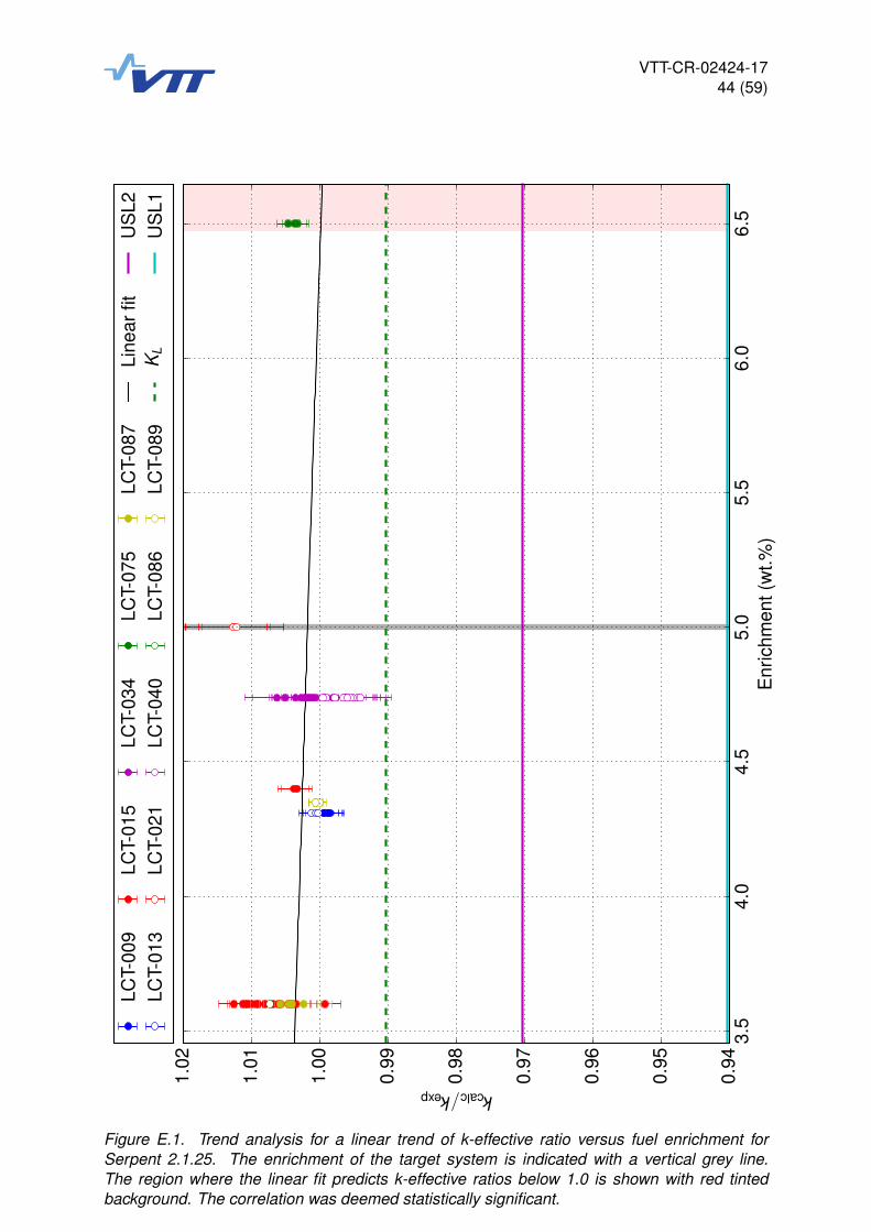
VTT-CR-02424-1744 (59)
3.5
4.0
4.5
5.0
5.5
6.0
6.5
Enr
ichm
ent(
wt.%
)
0.94
0.95
0.96
0.97
0.98
0.99
1.00
1.01
1.02
kcalc/kexpLC
T-00
9LC
T-01
3LC
T-01
5LC
T-02
1LC
T-03
4LC
T-04
0LC
T-07
5LC
T-08
6LC
T-08
7LC
T-08
9Li
near
fitK
L
US
L2U
SL1
Figure E.1. Trend analysis for a linear trend of k-effective ratio versus fuel enrichment forSerpent 2.1.25. The enrichment of the target system is indicated with a vertical grey line.The region where the linear fit predicts k-effective ratios below 1.0 is shown with red tintedbackground. The correlation was deemed statistically significant.
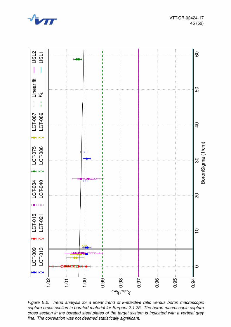
VTT-CR-02424-1745 (59)
010
2030
4050
60B
oron
Sig
ma
(1/c
m)
0.94
0.95
0.96
0.97
0.98
0.99
1.00
1.01
1.02
kcalc/kexpLC
T-00
9LC
T-01
3LC
T-01
5LC
T-02
1LC
T-03
4LC
T-04
0LC
T-07
5LC
T-08
6LC
T-08
7LC
T-08
9Li
near
fitK
L
US
L2U
SL1
Figure E.2. Trend analysis for a linear trend of k-effective ratio versus boron macroscopiccapture cross section in borated material for Serpent 2.1.25. The boron macroscopic capturecross section in the borated steel plates of the target system is indicated with a vertical greyline. The correlation was not deemed statistically significant.
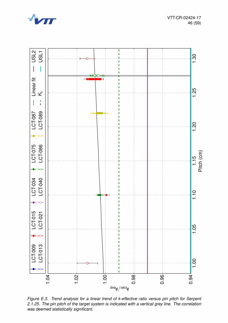
VTT-CR-02424-1746 (59)
1.00
1.05
1.10
1.15
1.20
1.25
1.30
Pitc
h(c
m)
0.94
0.96
0.98
1.00
1.02
1.04
kcalc/kexpLC
T-00
9LC
T-01
3LC
T-01
5LC
T-02
1LC
T-03
4LC
T-04
0LC
T-07
5LC
T-08
6LC
T-08
7LC
T-08
9Li
near
fitK
L
US
L2U
SL1
Figure E.3. Trend analysis for a linear trend of k-effective ratio versus pin pitch for Serpent2.1.25. The pin pitch of the target system is indicated with a vertical grey line. The correlationwas deemed statistically significant.

VTT-CR-02424-1747 (59)
0.0
0.5
1.0
1.5
EA
LF(e
V)
0.94
0.95
0.96
0.97
0.98
0.99
1.00
1.01
1.02
kcalc/kexpLC
T-00
9LC
T-01
3LC
T-01
5LC
T-02
1LC
T-03
4LC
T-04
0LC
T-07
5LC
T-08
6LC
T-08
7LC
T-08
9Li
near
fitK
L
US
L2U
SL1
Figure E.4. Trend analysis for a linear trend of k-effective ratio versus EALF for Serpent 2.1.25.The EALF of the target system is indicated with a vertical grey line. The correlation was notdeemed statistically significant.

VTT-CR-02424-1748 (59)
F Trend analysis plots for Serpent 2.1.27

VTT-CR-02424-1749 (59)
3.5
4.0
4.5
5.0
5.5
6.0
6.5
Enr
ichm
ent(
wt.%
)
0.94
0.95
0.96
0.97
0.98
0.99
1.00
1.01
1.02
kcalc/kexpLC
T-00
9LC
T-01
3LC
T-01
5LC
T-02
1LC
T-03
4LC
T-04
0LC
T-07
5LC
T-08
6LC
T-08
7LC
T-08
9Li
near
fitK
L
US
L2U
SL1
Figure F.1. Trend analysis for a linear trend of k-effective ratio versus fuel enrichment forSerpent 2.1.27. The enrichment of the target system is indicated with a vertical grey line.The region where the linear fit predicts k-effective ratios below 1.0 is shown with red tintedbackground. The correlation was deemed statistically significant.
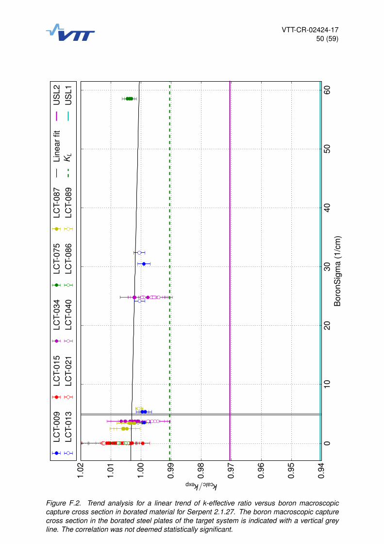
VTT-CR-02424-1750 (59)
010
2030
4050
60B
oron
Sig
ma
(1/c
m)
0.94
0.95
0.96
0.97
0.98
0.99
1.00
1.01
1.02
kcalc/kexpLC
T-00
9LC
T-01
3LC
T-01
5LC
T-02
1LC
T-03
4LC
T-04
0LC
T-07
5LC
T-08
6LC
T-08
7LC
T-08
9Li
near
fitK
L
US
L2U
SL1
Figure F.2. Trend analysis for a linear trend of k-effective ratio versus boron macroscopiccapture cross section in borated material for Serpent 2.1.27. The boron macroscopic capturecross section in the borated steel plates of the target system is indicated with a vertical greyline. The correlation was not deemed statistically significant.

VTT-CR-02424-1751 (59)
1.00
1.05
1.10
1.15
1.20
1.25
1.30
Pitc
h(c
m)
0.94
0.96
0.98
1.00
1.02
1.04
kcalc/kexpLC
T-00
9LC
T-01
3LC
T-01
5LC
T-02
1LC
T-03
4LC
T-04
0LC
T-07
5LC
T-08
6LC
T-08
7LC
T-08
9Li
near
fitK
L
US
L2U
SL1
Figure F.3. Trend analysis for a linear trend of k-effective ratio versus pin pitch for Serpent2.1.27. The pin pitch of the target system is indicated with a vertical grey line. The correlationwas deemed statistically significant.

VTT-CR-02424-1752 (59)
0.0
0.5
1.0
1.5
EA
LF(e
V)
0.94
0.95
0.96
0.97
0.98
0.99
1.00
1.01
1.02
kcalc/kexpLC
T-00
9LC
T-01
3LC
T-01
5LC
T-02
1LC
T-03
4LC
T-04
0LC
T-07
5LC
T-08
6LC
T-08
7LC
T-08
9Li
near
fitK
L
US
L2U
SL1
Figure F.4. Trend analysis for a linear trend of k-effective ratio versus EALF for Serpent 2.1.27.The EALF of the target system is indicated with a vertical grey line. The correlation was notdeemed statistically significant.

VTT-CR-02424-1753 (59)
G Trend analysis plots for Serpent 2.1.28

VTT-CR-02424-1754 (59)
3.5
4.0
4.5
5.0
5.5
6.0
6.5
Enr
ichm
ent(
wt.%
)
0.94
0.95
0.96
0.97
0.98
0.99
1.00
1.01
1.02
kcalc/kexpLC
T-00
9LC
T-01
3LC
T-01
5LC
T-02
1LC
T-03
4LC
T-04
0LC
T-07
5LC
T-08
6LC
T-08
7LC
T-08
9Li
near
fitK
L
US
L2U
SL1
Figure G.1. Trend analysis for a linear trend of k-effective ratio versus fuel enrichment forSerpent 2.1.28. The enrichment of the target system is indicated with a vertical grey line.The region where the linear fit predicts k-effective ratios below 1.0 is shown with red tintedbackground. The correlation was deemed statistically significant.

VTT-CR-02424-1755 (59)
010
2030
4050
60B
oron
Sig
ma
(1/c
m)
0.94
0.95
0.96
0.97
0.98
0.99
1.00
1.01
1.02
kcalc/kexpLC
T-00
9LC
T-01
3LC
T-01
5LC
T-02
1LC
T-03
4LC
T-04
0LC
T-07
5LC
T-08
6LC
T-08
7LC
T-08
9Li
near
fitK
L
US
L2U
SL1
Figure G.2. Trend analysis for a linear trend of k-effective ratio versus boron macroscopiccapture cross section in borated material for Serpent 2.1.28. The boron macroscopic capturecross section in the borated steel plates of the target system is indicated with a vertical greyline. The correlation was not deemed statistically significant.

VTT-CR-02424-1756 (59)
1.00
1.05
1.10
1.15
1.20
1.25
1.30
Pitc
h(c
m)
0.94
0.96
0.98
1.00
1.02
1.04
kcalc/kexpLC
T-00
9LC
T-01
3LC
T-01
5LC
T-02
1LC
T-03
4LC
T-04
0LC
T-07
5LC
T-08
6LC
T-08
7LC
T-08
9Li
near
fitK
L
US
L2U
SL1
Figure G.3. Trend analysis for a linear trend of k-effective ratio versus pin pitch for Serpent2.1.28. The pin pitch of the target system is indicated with a vertical grey line. The correlationwas deemed statistically significant.
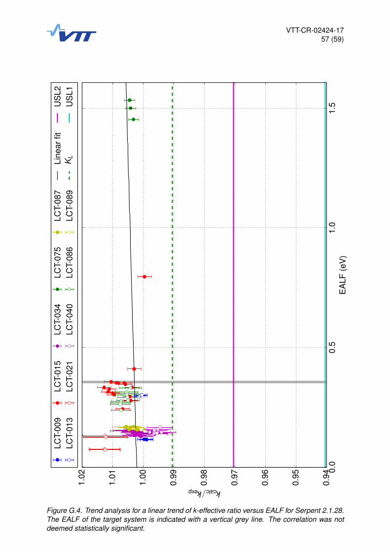
VTT-CR-02424-1757 (59)
0.0
0.5
1.0
1.5
EA
LF(e
V)
0.94
0.95
0.96
0.97
0.98
0.99
1.00
1.01
1.02
kcalc/kexpLC
T-00
9LC
T-01
3LC
T-01
5LC
T-02
1LC
T-03
4LC
T-04
0LC
T-07
5LC
T-08
6LC
T-08
7LC
T-08
9Li
near
fitK
L
US
L2U
SL1
Figure G.4. Trend analysis for a linear trend of k-effective ratio versus EALF for Serpent 2.1.28.The EALF of the target system is indicated with a vertical grey line. The correlation was notdeemed statistically significant.
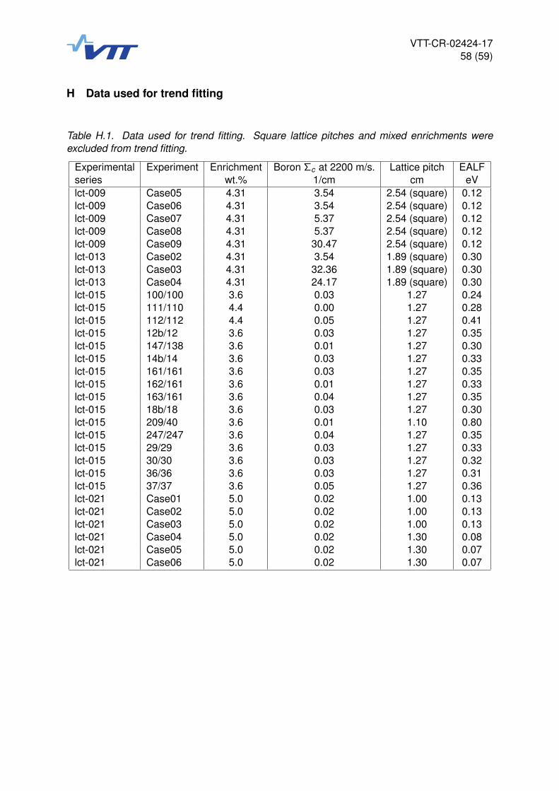
VTT-CR-02424-1758 (59)
H Data used for trend fitting
Table H.1. Data used for trend fitting. Square lattice pitches and mixed enrichments wereexcluded from trend fitting.
Experimental Experiment Enrichment Boron Σc at 2200 m/s. Lattice pitch EALFseries wt.% 1/cm cm eVlct-009 Case05 4.31 3.54 2.54 (square) 0.12lct-009 Case06 4.31 3.54 2.54 (square) 0.12lct-009 Case07 4.31 5.37 2.54 (square) 0.12lct-009 Case08 4.31 5.37 2.54 (square) 0.12lct-009 Case09 4.31 30.47 2.54 (square) 0.12lct-013 Case02 4.31 3.54 1.89 (square) 0.30lct-013 Case03 4.31 32.36 1.89 (square) 0.30lct-013 Case04 4.31 24.17 1.89 (square) 0.30lct-015 100/100 3.6 0.03 1.27 0.24lct-015 111/110 4.4 0.00 1.27 0.28lct-015 112/112 4.4 0.05 1.27 0.41lct-015 12b/12 3.6 0.03 1.27 0.35lct-015 147/138 3.6 0.01 1.27 0.30lct-015 14b/14 3.6 0.03 1.27 0.33lct-015 161/161 3.6 0.03 1.27 0.35lct-015 162/161 3.6 0.01 1.27 0.33lct-015 163/161 3.6 0.04 1.27 0.35lct-015 18b/18 3.6 0.03 1.27 0.30lct-015 209/40 3.6 0.01 1.10 0.80lct-015 247/247 3.6 0.04 1.27 0.35lct-015 29/29 3.6 0.03 1.27 0.33lct-015 30/30 3.6 0.03 1.27 0.32lct-015 36/36 3.6 0.03 1.27 0.31lct-015 37/37 3.6 0.05 1.27 0.36lct-021 Case01 5.0 0.02 1.00 0.13lct-021 Case02 5.0 0.02 1.00 0.13lct-021 Case03 5.0 0.02 1.00 0.13lct-021 Case04 5.0 0.02 1.30 0.08lct-021 Case05 5.0 0.02 1.30 0.07lct-021 Case06 5.0 0.02 1.30 0.07

VTT-CR-02424-1759 (59)
Table H.1. Data used for trend fitting (continues). Square lattice pitches and mixed enrichmentswere excluded from trend fitting.
Experimental Experiment Enrichment Boron Σc at 2200 m/s. Lattice pitch EALFseries wt.% 1/cm cm eVlct-034 Case01 4.74 3.77 1.60 (square) 0.15lct-034 Case02 4.74 3.77 1.60 (square) 0.15lct-034 Case03 4.74 3.77 1.60 (square) 0.14lct-034 Case04 4.74 3.77 1.60 (square) 0.14lct-034 Case05 4.74 3.77 1.60 (square) 0.14lct-034 Case06 4.74 3.77 1.60 (square) 0.13lct-034 Case07 4.74 3.77 1.60 (square) 0.13lct-034 Case08 4.74 3.77 1.60 (square) 0.13lct-034 Case10 4.74 24.78 1.60 (square) 0.15lct-034 Case11 4.74 24.78 1.60 (square) 0.15lct-034 Case12 4.74 24.78 1.60 (square) 0.15lct-034 Case13 4.74 24.78 1.60 (square) 0.14lct-034 Case14 4.74 24.78 1.60 (square) 0.14lct-034 Case15 4.74 24.78 1.60 (square) 0.14lct-040 Case01 4.74 3.77 1.60 (square) 0.15lct-040 Case02 4.74 3.77 1.60 (square) 0.17lct-040 Case03 4.74 3.77 1.60 (square) 0.16lct-040 Case04 4.74 3.77 1.60 (square) 0.15lct-040 Case05 4.74 24.78 1.60 (square) 0.14lct-040 Case06 4.74 24.78 1.60 (square) 0.15lct-040 Case07 4.74 24.78 1.60 (square) 0.14lct-040 Case08 4.74 24.78 1.60 (square) 0.14lct-040 Case09 4.74 24.78 1.60 (square) 0.15lct-040 Case10 4.74 24.78 1.60 (square) 0.15lct-075 Case01 6.5 58.51 1.10 1.53lct-075 Case02 6.5 58.51 1.10 1.50lct-075 Case03 6.5 58.51 1.10 1.45lct-086 Case1 4.4 0.03 1.27 0.33lct-086 Case2 3.6–4.4 (mixed) 0.03 1.27 0.31lct-086 Case3 3.3–4.4 (mixed) 0.03 1.27 0.31lct-086 Case4 3.0–4.4 (mixed) 0.03 1.27 0.30lct-086 Case5 2.0–4.4 (mixed) 0.03 1.27 0.28lct-086 Case6 3.6 0.03 1.27 0.28lct-086 Case7 3.6–4.4 (mixed) 0.03 1.27 0.29lct-086 Case8 3.3–3.6 (mixed) 0.03 1.27 0.27lct-086 Case9 3.0–3.6 (mixed) 0.03 1.27 0.26lct-086 Case10 2.0–3.6 (mixed) 0.03 1.27 0.24lct-087 Case3 3.6 2.49 1.22 0.17lct-087 Case4 3.6–4.4 (mixed) 2.49 1.22 0.17lct-087 Case5 3.6 3.42 1.22 0.17lct-087 Case6 3.6–4.4 (mixed) 3.42 1.22 0.17lct-087 Case9 3.6 2.49 1.22 0.16lct-087 Case10 3.6 3.42 1.22 0.16lct-087 Case11 3.6–4.4 (mixed) 3.42 1.22 0.16lct-089 Case01 4.35 5.92 1.50 (square) 0.16lct-089 Case02 4.35 5.92 1.50 (square) 0.16lct-089 Case03 4.35 5.92 1.50 (square) 0.16lct-089 Case04 4.35 5.92 1.50 (square) 0.16