Embed Size (px)
Citation preview
Cronfa - Swansea University Open Access Repository
_____________________________________________________________
This is an author produced version of a paper published in:
IEEE Electron Device Letters
Cronfa URL for this paper:
http://cronfa.swan.ac.uk/Record/cronfa39145
_____________________________________________________________
Paper:
Igic, P., Jankovic, N., Evans, J., Elwin, M., Batcup, S. & Faramehr, S. (2018). Dual-Drain GaN Magnetic Sensor
Compatible with GaN RF Power Technology. IEEE Electron Device Letters, 1-1.
http://dx.doi.org/10.1109/LED.2018.2816164
_____________________________________________________________ This item is brought to you by Swansea University. Any person downloading material is agreeing to abide by the terms
of the repository licence. Copies of full text items may be used or reproduced in any format or medium, without prior
permission for personal research or study, educational or non-commercial purposes only. The copyright for any work
remains with the original author unless otherwise specified. The full-text must not be sold in any format or medium
without the formal permission of the copyright holder.
Permission for multiple reproductions should be obtained from the original author.
Authors are personally responsible for adhering to copyright and publisher restrictions when uploading content to the
repository.
http://www.swansea.ac.uk/library/researchsupport/ris-support/
> REPLACE THIS LINE WITH YOUR PAPER IDENTIFICATION NUMBER (DOUBLE-CLICK HERE TO EDIT) <
1
Abstract— This letter presents first–ever
fabricated GaN split-current magnetic sensor device. Device operation and key manufacturing steps are also presented. The measured relative current sensitivity is constant at 14 % T-1 for wide mT range of the magnetic field. Constant sensitivity of a fabricated sensor can be attributed to device’s 2DEG nature, i.e. its high electron concentration and mobility, and very small layer thickness.
Index Terms — GaN, HEMT, MagFET, Magnetic
Sensor, Split-Current, Dual Drain
I. INTRODUCTION he potential for superior performance of Gallium Nitride (GaN) Wide-Band-Gap (WBG) power devices in medium
and high-voltage applications (600V – 1.2kV) is well recognised [1]. However, if this technology is to be used at its full potential, i.e. to switch faster at the higher power density at elevated temperatures, then real-time in-situ performance and condition monitoring is of crucial importance. One way of achieving this is to employ current monitoring techniques comprising of a magnetic sensor monolithically integrated with the power devices [2], [3], [4].
Magnetic sensing techniques exploit an extensive range of ideas and phenomena from the physics and material science fields [2], [3], [4]. The widely used magnetic sensors based on integrated circuit (IC) compatible sensing devices, such as the one based on complementary metal-oxide-semiconductor (CMOS) [5] and bipolar technologies [6] have modest sensitivity in the range of few mT comparing with the non-IC compatible magnetic sensors such as giant magnetoresistors and/or superconducting quantum interference device
(SQUID) having a sensitivity bellow nT. The CMOS compatible Hall-effect sensors mostly rely on using either the p-n junction isolated diffused Hall plates or the split-drain magnetic sensitive (MS) metal-oxide-semiconductor field-effect transistors (MagFETs) as magnetic sensitive elements [7], [8]. Both sensitive devices exploit a physical phenomenon that an electron moving through a magnetic field experiences a force, known as the Lorentz force, perpendicular to its direction of motion and to the direction of the field. It is the response to this force that creates the Hall voltage in semiconductor plates or a variation in electron current distribution detected as the current or voltage difference between two drain outputs of MagFETs.
Nowadays, most of the semiconductor sensor technologies are silicon based [8], [9], [10]. Obviously, to fully unlock GaN technology potential, the GaN current sensing devices are needed [11]. In this letter we described operation, manufactured and tested first-ever GaN dual-drain magnetic sensitive device fully compatible with the current RF Power GaN HEMT technology. Device concept has been confirmed by employing industrial standard SILVACO TCAD toolbox [12]. Finally, this novel dual-drain split-current magnetic sensor is suitable for the employment within the very advanced current monitoring technique, i.e. Galvanic-SenseFET current monitoring technique [13] comprising of a magnetic sensor monolithically integrated with the power devices.
II. DEVICE FABRICATION AND OPERATION PRINCIPLE
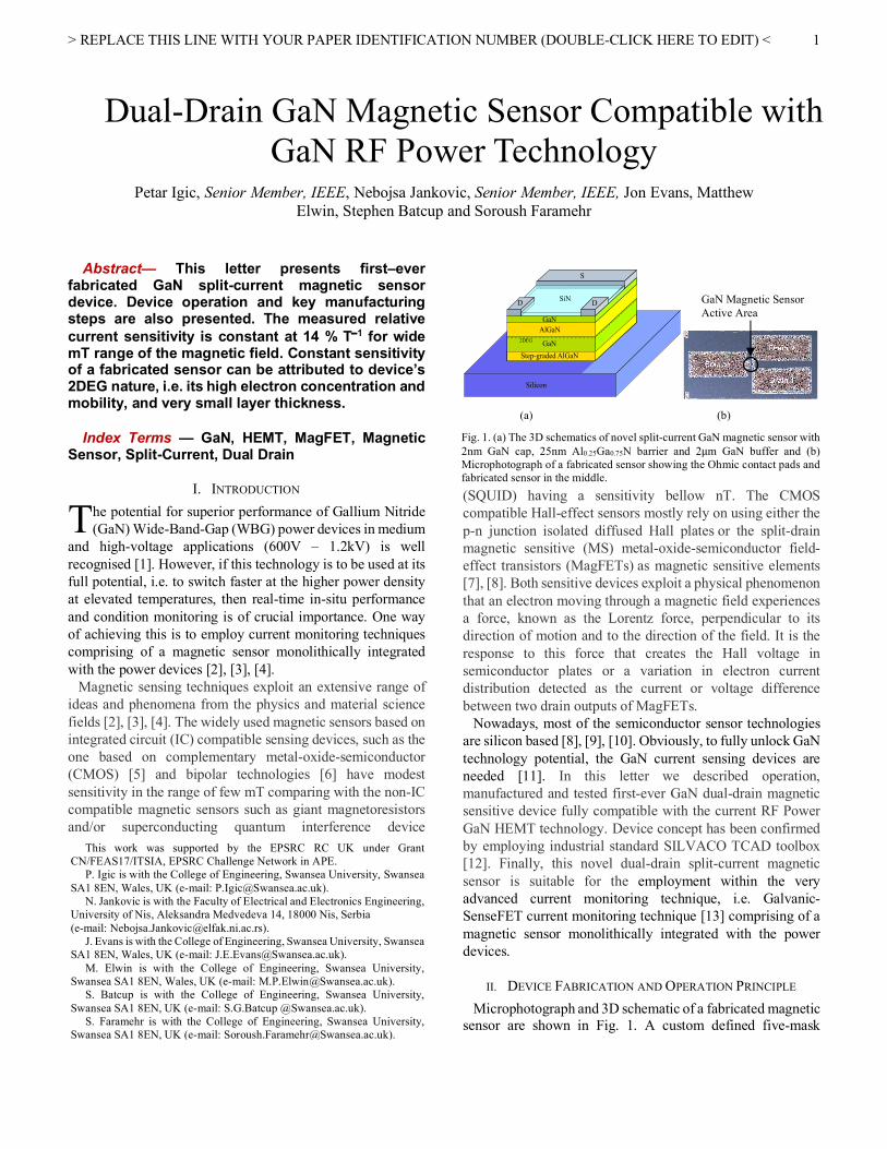
Microphotograph and 3D schematic of a fabricated magnetic sensor are shown in Fig. 1. A custom defined five-mask
Dual-Drain GaN Magnetic Sensor Compatible with GaN RF Power Technology
Petar Igic, Senior Member, IEEE, Nebojsa Jankovic, Senior Member, IEEE, Jon Evans, Matthew Elwin, Stephen Batcup and Soroush Faramehr
T
(a) (b)
Fig. 1. (a) The 3D schematics of novel split-current GaN magnetic sensor with 2nm GaN cap, 25nm Al0.25Ga0.75N barrier and 2µm GaN buffer and (b) Microphotograph of a fabricated sensor showing the Ohmic contact pads and fabricated sensor in the middle.
Silicon
GaN
AlGaNGaN
S
D DSiN
Step-graded AlGaN
2DEG
(b)
GaN Magnetic Sensor Active Area
This work was supported by the EPSRC RC UK under Grant CN/FEAS17/ITSIA, EPSRC Challenge Network in APE.
P. Igic is with the College of Engineering, Swansea University, Swansea SA1 8EN, Wales, UK (e-mail: [email protected]).
N. Jankovic is with the Faculty of Electrical and Electronics Engineering, University of Nis, Aleksandra Medvedeva 14, 18000 Nis, Serbia (e-mail: [email protected]).
J. Evans is with the College of Engineering, Swansea University, Swansea SA1 8EN, Wales, UK (e-mail: [email protected]).
M. Elwin is with the College of Engineering, Swansea University, Swansea SA1 8EN, Wales, UK (e-mail: [email protected]).
S. Batcup is with the College of Engineering, Swansea University, Swansea SA1 8EN, UK (e-mail: S.G.Batcup @Swansea.ac.uk).
S. Faramehr is with the College of Engineering, Swansea University, Swansea SA1 8EN, UK (e-mail: [email protected]).
> REPLACE THIS LINE WITH YOUR PAPER IDENTIFICATION NUMBER (DOUBLE-CLICK HERE TO EDIT) <
2
process was used. Starting material was 6-inch GaN on silicon-substrate wafer. Firstly, to configure device’s active region, device mesas were etched using a dry etch process in an inductively coupled plasma (ICP) system. A lift-off process was used to pattern Ti/Al/Au metal stack Ohmic contacts, which were sputtered deposited and then rapidly annealed at temperatures above 750OC for a short period of time under N2 ambient. Next, a standard SiN passivation layer was deposited via plasma enhanced chemical vapor deposition (PECVD). Finally, the passivation was removed from the contact areas using a fluorine based ICP etch.
To operate the magnetic sensor device, source contact is kept at 0V. When positive voltage is applied at D1 and D2 contacts, the drain electric field spreads throughout the device eventually reaching the source, thus allowing for the electric currents to flow between the source and the drains D1 and D2, IDS1 and IDS2 respectively. When no magnetic field is present, these two currents are identical (IDS1–IDS2=0). The presence of magnetic field will cause a deflection of electrons in the currents leading to current differences, IDS1–IDS2 = DI. By measuring DI one can determine the magnetic field value.
III. MAGNETIC SENSITIVITY TEST, RESULTS AND DISCUSSION
The probe station LA-150 bench-top system by INSETO was used to test the magnetic sensor sensitivity. It has a 150mm chuck with full x-y-z movement and dual-mode optics for both microscope and digital video viewing. The probe station connects the device under-test to a Keithley 4200-SCS semiconductor characterisation system with 200V/1A DC, pulse and CV measurement capability.
The magnetic field 𝐵#$$$$⃗ perpendicular to a chuck surface was produced by the coil embedded backside through the hole of chuck plate. By a precise control of coil supply current, the different field intensities &𝐵#$$$$⃗ &from 0 to 30mT in 1.25mT steps were generated in-situ which was verified using a precise digital magnetometer. Owning to a coil diameter (2cm) that is much larger than sensor dimension (35x20µm), it is justified to assume that the homogenous magnetic field 𝐵#$$$$⃗ was applied over the device area.
A common figure of merit of split-current magnetic sensors’ performance is current relative sensitivity 𝑆)defined as 𝑆) =ΔI- ∙ /I-&B$$⃗ 1&2
34∙ 100%, where 𝐼9 = 𝐼9:4 + 𝐼9:<is the total
drain current [2]. Fig. 2 shows the measured 𝑆=versus &𝐵#$$$$⃗ &extracted from testing a number of devices on the same GaN wafer, as well as simulated𝑆=. A split-current magnetic sensor (Fig. 1) is simulated in this paper using drift-diffusion transport model. The magnetic field effect is modelled using 3D MAGNETIC module of Silvaco Atlas [12]. The Fermi level at the surface of structure is pinned at EC =1.65eV. The unintentional oxygen and carbon impurity dopants resulting from precursor and carrier gases during the epitaxial growth are included into the GaN buffer layer at EC - ET = 0.11eV and EC - ET = 3.28eV, respectively [14]. The capture cross sections of electrons and holes are set to 𝜎?,A = 1 × 1034C cm2. The Shockley-Read-Hall (SRH) and Fermi-Dirac statistics are activated for all models. Nitrides mobility for low and high
fields are employed in the 3D simulations. Nitride parameters used in this paper are extracted from the literature [15]. Self-heating effects are neglected.
The electrical current distributions at |𝐵#$$$$$$⃗ | = 0T (Fig. 3(a)) and |𝐵#$$$$$$⃗ |= 30mT (Fig. 3(b)) are obtained at VDS = 0.5V where 𝐵#$$$$⃗ is the magnetic field along the y-axis (direction perpendicular to the device surface). The simulated current distribution in presence of magnetic field is a result of the Lorentz force and asymmetrical accumulation of electrons at the device’s 2DEG channel.
Different 𝑉9: biasing conditions were set to find optimal device sensitivity, for this particular device layout. Results shown in Fig. 2 were obtained for 𝑉9:4 = 𝑉9:< = 0.5𝑉 (source contact is kept at 0𝑉). A 𝑆=with a value around 14% T-1 at a wide range of magnetic fields and at 1mA of supply current is extracted from magnetic sensor measurements (Fig. 2). The outstanding constant sensitivity of a fabricated sensor across a wide range of the magnetic field values can be attributed to device’s 2DEG nature, i.e. its high electron concentration and mobility, and very small layer thickness.
In split-current sensors, similar to Hall sensor devices, a sensor response time is determined by the time needed by moving electrons to spatially relocate inside the semiconductor in order to respond to a time varying magnetic field. Sensor response time is very important device parameter determining potential sensor applications. It strongly depends on the resistivity of 2DEG, while the magnetic field density has a negligible effect on the response time [16]. Since the resistivity of the 2DEG is very low, in the region of 0.2 W×cm [17], the response time of the GaN sensor presented in this work can be estimated to be below nano-second [16]. Its potential applications can vary from the machine control purposes (kHz range) to current monitoring in the very-high frequency (VHF) power converters (hundreds of MHz range) [1].
Fig. 2. Measured and simulated dependences of 𝑆=versus &𝐵𝑦$$$⃗ & at total drain current 𝐼9 = 𝐼9:4 + 𝐼9:<=1mA. Squares are sensitivity results obtained from measurements, crosses are sensitivity calculations from simulation results and triangles are average of current imbalance in 12 fabricated GaN split-current magnetic sensors for various applied magnetic fields. The error bars are standard deviations of sensitivities calculated for 12 fabricated devices.
> REPLACE THIS LINE WITH YOUR PAPER IDENTIFICATION NUMBER (DOUBLE-CLICK HERE TO EDIT) <
3
Fig. 3. Simulated current distribution of split current magnetic sensor at VDS= 0.5V (a) no presence of external magnetic, 2DEG channel showing the symmetry in the current density; (b) external magnetic field perpendicular to the 2DEG channel is present, 2DEG channel showing current asymmetry.
IV. CONCLUSIONS The operation, fabrication and sensitivity measurement
results of the first-ever GaN technology-based split-current dual-drain magnetic sensor that is fully compatible (no extra materials or micromachining needed) with the GaN RF Power technology is described. Owning to high mobility of 2DEG electrons the fabricated prototype of 35µm×20µm magnetic sensing device exhibited 𝑆=with the constant value of 14 % T –1 at 1mA of supply current. The constant sensitivity can be attributed to the 2DEG’s nature (high electron concentration, high mobility and very small layer thickness).
ACKNOWLEDGMENT This work has been done in cooperation with IQE, UK and
CSC, UK.
REFERENCES [1] D. Kinzer, "GaN power IC technology: Past, present and future," in
Proceedings of the 29th Interbational Symposium on Power Semicondcutor Devices and ICs (ISPSD), 2017, pp. 19-24, doi: 10.23919/ISPSD.2017.7988981
[2] H. Konno and H. Kataniwa, “Integrated ferromagnetic MR sensors,” J. Appl. Phys., vol. 69, no. 8, pp. 5933–5935, Apr. 1991, doi: http://dx.doi.org/10.1063/1.347820
[3] T. J. Brauhn, M. Sheng, B. A. Dow, H. Nogawa and R. D. Lorenz, “Module-Integrated GMR-Based Current Sensing for Closed-Loop Control of a Motor Drive,” IEEE Trans. Ind. Appl., vol. 53, no. 1, pp. 222–231, Jan. 2017, doi: 10.1109/TIA.2016.2614771
[4] H. P. Baltes and R. S. Popovic, “Integrated semiconductor magnetic field sensors,” Proc. IEEE, vol. 74, no. 8, pp. 1107–1132, 1986, doi: 10.1109/PROC.1986.13597
[5] J. Lenz and S. Edelstein, "Magnetic sensors and their applications, " IEEE Sensors Journal, vol. 6, no. 3, pp. 631-649, June 2006, doi: 10.1109/JSEN.2006.874493
[6] N. Rangaraju, J.A. Peters and B.W. Wessels, "Magnetoamplification in a Bipolar Magnetic Junction Transistor,” Physical Review Lett., PRL 105, pp. 117202-1 - 117202-4, Sep. 2010, doi: 10.1103/PhysRevLett.105.117202
[7] A. B. Sachid, Y.-M. Huang, Y.-J. Chen, C.-C. Chen, D. D. Lu, M.-C. Chen and C. Hu, “FinFET With Encased Air-Gap Spacers for High-Performance and Low-Energy Circuits,” IEEE Electron Device Lett., vol. 38, no. 1, pp. 16–19, Jan. 2017, doi: 10.1109/LED.2016.2628768
[8] D. Flandre, A. Adriaensen, A. Afzalian, J. Laconte, D. Levacq, C. Renaux, L. Vancaillie, J.-P. Raskin, L. Demeus, P. Delatte, V. Dessard and G. Picun, “Intelligent SOI CMOS integrated circuits and sensors for heterogeneous environments and applications,” in Proceedings of IEEE Sensors, vol. 2, 2002, pp. 1407–1412, doi: 10.1109/ICSENS.2002.1037327
[9] N. Jankovic, O. Kryvchenkova, S. Batcup and P. Igic, "High Sensitivity Dual-Gate Fout-Terminal Magnetic Sensor Compatible With SOI FinFET TEchnology," IEEE Elec. Device Lett., Vol. 38, No. 6, pp. 810-813, June 2017, doi: 10.1109/LED.2017.2693559
[10] A. L. Perin and R. Giacomini, “Sensing magnetic fields in any direction using FinFETs and L-gate FinFETs,” in 2012 IEEE International SOI Conference (SOI), 2012, pp. 1–2, doi: 10.1109/SOI.2012.6404368
[11] L. Bouguen, S. Contreras, B. Jouault, L. Konczewicz, J. Camassel, Y. Cordier, M. Azize, S. Chenot and N. Baron, "Investigation of AlGaN/AlN/GaN heterostructures for magnetic sensor application from liquid helium temperature to 300OC," Appl. Phys. Lett., vol. 92, no. 4, pp. 043504-1 - 043504-3, 2008, doi: doi.org/10.1063/1.2838301
[12] Atlas User’s Manual, SILVACO International, Santa Clara, CA, USA, 2007.
[13] S. Rao, Q. Khan, S. Bang, D. Swank, A. Rao, W. McIntyre and P.K. Hanumolu, "A 1.2-A Buck-Boost LED Driver With On-Chip Error Averaged SenseFET-Based Current Sensing Technique," IEEE Journal of Solid-State Circ., vol. 46, no. 12, pp. 1-12, Dec. 2011, doi: 10.1109/JSSC.2011.2162921
[14] S. Faramehr, K. Kalna, and P. Igić, “Drift-diffusion and hydrodynamic modeling of current collapse in GaN HEMTs for RF power application,” Semicond. Sci. Technol., vol. 29, no. 2, pp. 025007-025017, Jan. 2014, doi:10.1088/0268-1242/29/2/025007
[15] R. Quay, Gallium nitride electronics. Berlin: Springer-Verlag, 2008. [16] M. Crescentini, A. Romani and E. Sangiorgi, "Physical Simulations
of Response Time in Hall Sensor Devices," in Proceedings of the 15th IEEE International Conference on Ultimate Integration on Silicon (ULIS), 2014, pp. 89-92, doi: 10.1109/ULIS.2014.6813923
[17] H. Li, C. Yao, C. Han, J.A. Brothers, X. Zhang, J. Wang, "Evaluation of 600V GaN based gate injection transistor for high temperature and high efficiency application," In Proceedings of IEEE 3rd Workshop on Wide Bandgap Power Devices and Applications (WiPDA), 2015, pp. 85-91, doi: 10.1109/WiPDA.2015.7369300
S
D
D
S
D
D
(a)
(b)


![Cronfa - Swansea University Open Access Repository · 2017-05-03 · terms of the repository licence. ... (that was previously calibrated against Silvaco's [23] NEGF simulations [24])](https://img.pdfslide.net/doc/110x75/5b2a89197f8b9a1a298b4751/cronfa-swansea-university-open-access-repository-2017-05-03-terms-of-the.jpg)


![Cronfa - Swansea University Open Access Repository · 2017-03-06 · terms of the repository licence. ... using the simulation tool ATLAS by Silvaco [12]. The developed methodology](https://img.pdfslide.net/doc/110x75/5b2a89197f8b9a1a298b472f/cronfa-swansea-university-open-access-repository-2017-03-06-terms-of-the.jpg)


![Cronfa - Swansea University Open Access Repository · HQWRPRSDWKRJHQLFIXQJXV 0HWDUKL]LXPEUXQQHXP DQGWKHPRVTXLWRSUHGDWRU 7R[RUK\QFKLWHVEUHYLSDOSLV IRU FRQWURORIPRVTXLWRODUYDH ,VWKLVDULVN\ELRFRQWUROVWUDWHJ\"](https://img.pdfslide.net/doc/110x75/5f7facec7e11967ab1746190/cronfa-swansea-university-open-access-repository-hqwrprsdwkrjhqlfixqjxv-0hwdukllxpeuxqqhxp.jpg)


![Cronfa - Swansea University Open Access Repository · ô ½ ·W=m] Y](https://img.pdfslide.net/doc/110x75/5e086d1104eac94d302c30f1/cronfa-swansea-university-open-access-repository-wm-y.jpg)