Embed Size (px)
Citation preview

Cross Layer Feedback Architecture for Mobile DeviceProtocol Stacks
Submitted in partial fulfillment of the requirements
For the degree of
Doctor of Philosophy
by
Vijay Thakurdas Raisinghani
(Roll No: 01429703)
Supervisor
Prof. Sridhar Iyer
K.R. School of Information Technology
INDIAN INSTITUTE OF TECHNOLOGY, BOMBAY
2006


To my Father
(Late Shri Thakurdas M. Raisinghani)
i


Approval Sheet
Thesis entitled Cross Layer Feedback Architecture for Mobile Device Protocol
Stacks by Vijay Thakurdas Raisinghani (01429703) is approved for the degree of
Doctor of Philosophy
Examiners
Supervisor(s)
Chairman
Date:
Place:
iii


INDIAN INSTITUTE OF TECHNOLOGY, BOMBAY, INDIA
CERTIFICATE OF COURSE WORK
This is to certify that Mr. Vijay Thakurdas Raisinghani was admitted to the candidacy
of the Ph.D degree in July 2002, after successfully completing all the courses required for
the Ph.D Degree Programme. The details of the course work done are given below:
Sr. No. Course No. Course Name Credits
1 IT 620 Seminar 4
2 IT 642 Data Warehousing and Data Mining 6
3 IT 690 Mini Project 10
I.I.T Bombay
Date:
Dy. Registrar (Academic)
v

Abstract
Applications using traditional protocol stacks (for example, TCP/IP) from wired networks
do not function efficiently in mobile wireless scenarios. This is primarily due to the layered
architecture and implementation of protocol stacks.
Cross layer feedback is one of the mechanisms to improve the performance of a layered
stack in mobile wireless environments. For example, transport layer retransmissions could
be reduced by making it aware of network disconnections or hand-off events. One such
optimization is Receiver Window Control.
Since the protocol stack is an integral part of the operating system, any cross layer
modification to the stack should not impact its correctness, efficiency and maintainability.
An appropriate architecture would help ensure that cross layer modifications confirm to
these requirements.
We define the design goals for a cross layer architecture based on our study of the
pros and cons of existing approaches to cross layer feedback. We present our architec-
ture ECLAIR which addresses these design goals. In ECLAIR we exploit the fact that
stack behavior is determined by the values stored in various protocol data structures.
Our architecture facilitates easy manipulation of these values stored in the protocol data
structures. ECLAIR requires minimal or no modification to the existing protocol stack.
We validate and evaluate ECLAIR through a prototype implementation, of receiver
window control, and experiments. To evaluate a cross layer architecture we identify met-
rics for evaluation against each of the design goals. We identify time and space overhead,
user-kernel crossing, data path delay, number of changes to protocol stack and number of
changes to cross layer optimization as metrics for the design goals. Our results and anal-
yses show that ECLAIR is an efficient cross layer architecture and is easily maintainable.
To further enhance the efficiency of ECLAIR we propose a core sub-architecture.
Finally, we also present a design guide for cross layer optimizations using ECLAIR.
vii


Contents
1 Introduction 1
1.1 Cross Layer Feedback . . . . . . . . . . . . . . . . . . . . . . . . . . . . . . 3
1.2 Cross Layer Feedback Implementation . . . . . . . . . . . . . . . . . . . . 4
1.3 Cross Layer Feedback Architecture Design Goals . . . . . . . . . . . . . . . 6
1.4 Problem Definition . . . . . . . . . . . . . . . . . . . . . . . . . . . . . . . 6
1.5 Solution Outline . . . . . . . . . . . . . . . . . . . . . . . . . . . . . . . . . 7
1.6 Contributions of this Thesis . . . . . . . . . . . . . . . . . . . . . . . . . . 8
1.7 Organization of Thesis . . . . . . . . . . . . . . . . . . . . . . . . . . . . . 9
2 Motivation and Related Work 11
2.1 Introduction . . . . . . . . . . . . . . . . . . . . . . . . . . . . . . . . . . . 11
2.2 Cross Layer Feedback . . . . . . . . . . . . . . . . . . . . . . . . . . . . . . 12
2.3 Existing Approaches to Cross Layer Feedback . . . . . . . . . . . . . . . . 18
2.4 Problems with Modifying the Stack . . . . . . . . . . . . . . . . . . . . . . 24
2.5 Cross Layer Feedback Architecture Design Goals . . . . . . . . . . . . . . . 25
2.6 Summary . . . . . . . . . . . . . . . . . . . . . . . . . . . . . . . . . . . . 29
3 ECLAIR: An Efficient Cross Layer Architecture 31
3.1 Introduction . . . . . . . . . . . . . . . . . . . . . . . . . . . . . . . . . . . 31
3.2 Background: Protocol Implementation Overview . . . . . . . . . . . . . . . 32
3.3 ECLAIR Overview . . . . . . . . . . . . . . . . . . . . . . . . . . . . . . . 34
3.4 Cross Layer Feedback using ECLAIR: Examples . . . . . . . . . . . . . . . 37
3.5 ECLAIR Details: Tuning Layer Specification . . . . . . . . . . . . . . . . . 41
3.6 Optimizing SubSystem Specification . . . . . . . . . . . . . . . . . . . . . . 53
3.7 ECLAIR Salient Features . . . . . . . . . . . . . . . . . . . . . . . . . . . 56
3.8 Summary . . . . . . . . . . . . . . . . . . . . . . . . . . . . . . . . . . . . 57
4 ECLAIR Validation 59
4.1 Receiver Window Control . . . . . . . . . . . . . . . . . . . . . . . . . . . 59
4.2 RWC Simulations . . . . . . . . . . . . . . . . . . . . . . . . . . . . . . . . 61
ix

x CONTENTS
4.3 Receiver Window Control Implementation using ECLAIR/Linux . . . . . . 63
4.4 RWC Experiments . . . . . . . . . . . . . . . . . . . . . . . . . . . . . . . 66
4.5 Summary . . . . . . . . . . . . . . . . . . . . . . . . . . . . . . . . . . . . 71
5 ECLAIR Evaluation 73
5.1 Evaluation Metrics . . . . . . . . . . . . . . . . . . . . . . . . . . . . . . . 73
5.2 Qualitative Evaluation . . . . . . . . . . . . . . . . . . . . . . . . . . . . . 76
5.3 Quantitative Efficiency Evaluation for RWC . . . . . . . . . . . . . . . . . 86
5.4 ECLAIR Overhead Measurement . . . . . . . . . . . . . . . . . . . . . . . 94
5.5 ECLAIR Limitations . . . . . . . . . . . . . . . . . . . . . . . . . . . . . . 109
5.6 Security Issues . . . . . . . . . . . . . . . . . . . . . . . . . . . . . . . . . . 110
5.7 Summary . . . . . . . . . . . . . . . . . . . . . . . . . . . . . . . . . . . . 110
6 ECLAIR Optimizations 113
6.1 Identifying Critical Data Items . . . . . . . . . . . . . . . . . . . . . . . . 114
6.2 Sub-architecture for Cross Layer Feedback . . . . . . . . . . . . . . . . . . 114
6.3 Example Usage Scenario . . . . . . . . . . . . . . . . . . . . . . . . . . . . 117
6.4 Summary . . . . . . . . . . . . . . . . . . . . . . . . . . . . . . . . . . . . 118
7 Cross Layer Design and Implementation Guide 121
7.1 Selecting Cross Layer Architecture . . . . . . . . . . . . . . . . . . . . . . 121
7.2 ECLAIR Design Guide . . . . . . . . . . . . . . . . . . . . . . . . . . . . . 126
7.3 ECLAIR Implementation Guide . . . . . . . . . . . . . . . . . . . . . . . . 128
7.4 Summary . . . . . . . . . . . . . . . . . . . . . . . . . . . . . . . . . . . . 130
8 Summary and Conclusions 131
8.1 Thesis Contributions . . . . . . . . . . . . . . . . . . . . . . . . . . . . . . 131
8.2 ECLAIR Application . . . . . . . . . . . . . . . . . . . . . . . . . . . . . . 133
8.3 Future Work . . . . . . . . . . . . . . . . . . . . . . . . . . . . . . . . . . . 133
Appendix I 137
I-1 TCP TL APIs . . . . . . . . . . . . . . . . . . . . . . . . . . . . . . . . . . 137
I-2 Mobile-IP TL APIs . . . . . . . . . . . . . . . . . . . . . . . . . . . . . . . 138
I-3 802.11 MAC TL APIs . . . . . . . . . . . . . . . . . . . . . . . . . . . . . 139
I-4 802.11 Phy TL APIs . . . . . . . . . . . . . . . . . . . . . . . . . . . . . . 140
Bibliography 143
List of Publications 153

List of Figures
1.1 Typical mobile wireless scenario . . . . . . . . . . . . . . . . . . . . . . . . 1
1.2 TCP/IP protocol stack[74] . . . . . . . . . . . . . . . . . . . . . . . . . . . 2
1.3 ECLAIR architecture . . . . . . . . . . . . . . . . . . . . . . . . . . . . . . 7
2.1 Cross layer feedback: Modification to protocol stack . . . . . . . . . . . . . 25
2.2 Cross layer feedback classification . . . . . . . . . . . . . . . . . . . . . . . 28
3.1 ECLAIR architecture . . . . . . . . . . . . . . . . . . . . . . . . . . . . . . 35
3.2 ECLAIR architecture details . . . . . . . . . . . . . . . . . . . . . . . . . . 36
3.3 ECLAIR architecture: User feedback . . . . . . . . . . . . . . . . . . . . . 38
3.4 ECLAIR architecture: Adapted TCP . . . . . . . . . . . . . . . . . . . . . 39
3.5 ECLAIR architecture: Seamless mobility . . . . . . . . . . . . . . . . . . . 40
3.6 ECLAIR Tuning Layers - Software component view . . . . . . . . . . . . . 41
3.7 ECLAIR Tuning Layers - Interfaces with PO . . . . . . . . . . . . . . . . . 44
3.8 User Tuning Layer Interfaces . . . . . . . . . . . . . . . . . . . . . . . . . . 46
3.9 Application Tuning Layer Interfaces . . . . . . . . . . . . . . . . . . . . . . 49
3.10 ECLAIR Optimizing SubSystem - Software component view . . . . . . . . 54
4.1 Receiver Window Control . . . . . . . . . . . . . . . . . . . . . . . . . . . 61
4.2 RWC: Simulation setup . . . . . . . . . . . . . . . . . . . . . . . . . . . . . 61
4.3 RWC: Simulation results . . . . . . . . . . . . . . . . . . . . . . . . . . . . 62
4.4 /usr/src/linux-2.4/include/net/sock.h source code snippet . . . . . . . . . 63
4.5 Call flow: RWC using ECLAIR . . . . . . . . . . . . . . . . . . . . . . . . 64
4.6 rwc user.c source code snippet. RWC PO and TL . . . . . . . . . . . . . . 65
4.7 RWC: Experiment setup . . . . . . . . . . . . . . . . . . . . . . . . . . . . 67
4.8 Receiver Window Control experiments over wireline (Ethernet) . . . . . . . 67
4.9 RWC: Experiment setup . . . . . . . . . . . . . . . . . . . . . . . . . . . . 68
4.10 Receiver Window Control experiments over WLAN (802.11) . . . . . . . . 69
5.1 Protocol stack schematic . . . . . . . . . . . . . . . . . . . . . . . . . . . . 88
5.2 Receiver Window Control implementation . . . . . . . . . . . . . . . . . . 89
xi

xii LIST OF FIGURES
5.3 Receiver Window Control: Structure chart – user-space . . . . . . . . . . . 90
5.4 Receiver Window Control: Structure chart – ECLAIR . . . . . . . . . . . . 90
5.5 Sequence diagram of data send and receive paths for an unmodified protocol
stack . . . . . . . . . . . . . . . . . . . . . . . . . . . . . . . . . . . . . . . 93
5.6 Data send and receive with RWC: (a) user-space (b) ECLAIR . . . . . . . 93
5.7 MAGNET details [28] . . . . . . . . . . . . . . . . . . . . . . . . . . . . . 96
5.8 LTT details [87] . . . . . . . . . . . . . . . . . . . . . . . . . . . . . . . . . 96
5.9 Data path delay comparison: ECLAIR v/s TCP modification . . . . . . . . 101
5.10 User-kernel crossing + socket search time: ECLAIR v/s setsockopt() . . . 106
6.1 ECLAIR with Core . . . . . . . . . . . . . . . . . . . . . . . . . . . . . . . 115
6.2 Core algorithm . . . . . . . . . . . . . . . . . . . . . . . . . . . . . . . . . 117
7.1 Cross layer feedback per packet . . . . . . . . . . . . . . . . . . . . . . . . 122
7.2 Cross layer feedback per flow/across flows . . . . . . . . . . . . . . . . . . 124

List of Tables
2.1 Cross layer feedback possibilities and relevant references . . . . . . . . . . 19
3.1 Table of acronyms . . . . . . . . . . . . . . . . . . . . . . . . . . . . . . . . 33
4.1 Mean and standard deviation of Flow 1 and 2 throughput . . . . . . . . . 70
5.1 Time overhead comparison . . . . . . . . . . . . . . . . . . . . . . . . . . . 77
5.2 Space overhead comparison . . . . . . . . . . . . . . . . . . . . . . . . . . 78
5.3 User-kernel crossing comparison . . . . . . . . . . . . . . . . . . . . . . . . 80
5.4 Data path delay comparison . . . . . . . . . . . . . . . . . . . . . . . . . . 81
5.5 Rapid Prototyping capability and Degree of Intrusion comparison . . . . . 83
5.6 Portability comparison . . . . . . . . . . . . . . . . . . . . . . . . . . . . . 84
5.7 Comparison of cross layer architectures: Summary . . . . . . . . . . . . . . 85
5.8 Cross Layer Architectures: Summary observations . . . . . . . . . . . . . . 86
5.9 ECLAIR and user-space quantitative comparison summary . . . . . . . . . 94
5.10 Data path delay: Mean and standard deviation for low packet rate . . . . . 102
5.11 Data path delay: Mean and standard deviation for high packet rate . . . . 103
5.12 Mean and standard deviation: No array used; CPU caching allowed . . . . 107
5.13 Mean and standard deviation: No array used; CPU cache invalidated . . . 107
5.14 Mean and standard deviation: Array used; CPU caching allowed . . . . . . 108
5.15 Mean and standard deviation: Array used; CPU cache invalidated . . . . . 108
7.1 Architecture Selection: Weighted Rank - Example 1 . . . . . . . . . . . . . 125
7.2 Architecture Selection: Weighted Rank - Example 2 . . . . . . . . . . . . . 125
xiii

xiv
This page has been intentionally left blank

Begin at the beginning and go on till you come to the end; then stop.
- Lewis Carroll
Chapter 1
Introduction
The TCP/IP (Transmission Control Protocol/Internet Protocol [70]) protocol stack
has been standardized for connecting to the Internet, using wireline devices (example
desktop PCs). This protocol stack is also being deployed on mobile wireless nodes (3G
and beyond [37, 76]), to ensure interoperability with the existing Internet. Figure 1.1
shows a typical mobile wireless setup. Wireless nodes in this setup are the base station
and the mobile wireless devices.
Wired network
Fixed host
Base station
Mobile device
Figure 1.1: Typical mobile wireless scenario
The architecture and implementation of a TCP/IP stack is layered [35]. Figure 1.2
shows a typical TCP/IP stack. In a layered stack, a layer does not share information
1

2
about its state with any other layer. For example, layers such as TCP or IP are not aware
of disconnection or handoff at the lower layers. This leads to inefficient functioning of the
layered stack in mobile wireless environments [75, 85]. On a mobile device, this inefficient
functioning would lead to poor user experience, decreased throughput, decreased battery
life, etc. We highlight this inefficiency of a layered stack by using TCP as an example.
Application
Transport
Network
Data link / MAC
Physical
User programs, interface, higher layer protocols
Connection management, flow control, end−to−end layer
Error free transmission, medium access
Transmission of raw bits
Routing, addressing
Figure 1.2: TCP/IP protocol stack[74]
Example – TCP over wireless:
TCP is an end-to-end reliable transport protocol [61]. A TCP sender uses acknowledg-
ments from the receiver as a signal to send additional packets. A missing acknowledgment
is interpreted as an indication of packet loss due to congestion in the network. However,
in mobile wireless environments packet losses could occur due to poor wireless channel
conditions and disconnections. Since TCP is unaware of these channel conditions it in-
vokes its congestion and retransmission algorithms [52, 61]. This response of TCP is
inappropriate for mobile wireless networks [75], because it results in unnecessary reduc-
tion in TCP throughput. There are various mechanisms for improving protocol stack
performance over mobile wireless networks. Some examples for TCP are TCP-Jersey [84],
TCP k-SACK [18], I-TCP [6], Snoop [8], early fast retransmit [16], TCP-Casablanca [11]
and COPAS [24] (for ad hoc networks). A survey of various optimizations for TCP is
provided in the references [7, 58, 75].
Cross Layer Feedback:
Out of the various mechanisms for improving TCP, one method is cross layer feedback [30,
38, 43, 65]. If TCP is made aware of the wireless network conditions (information available
at lower layers), its behavior could be improved [16, 29]. For example, TCP’s congestion
algorithms could be adapted or the retransmissions could be controlled using information
from the network layer [16]. This information exchange between layers (network layer and
TCP in this example) is known as cross layer feedback. Using cross layer feedback the
performance of layers other than TCP can also be improved (see Chapter 2 for a survey).

1.1. CROSS LAYER FEEDBACK 3
Improvements using cross layer feedback have been proposed earlier for wired networks
also in references [19, 20, 22].
Cross layer feedback optimizations may be implemented at the intermediate nodes
(base station, router, etc – see Figure 1.1) or mobile hosts(MH). Cross layer feedback
is not required at the fixed host, since it is not connected to a mobile wireless network.
Some of the proposals for cross layer feedback in the intermediate nodes are: snoop [8],
channel state dependent packet scheduling [10] and multi-service link layer [86]. Examples
of cross layer optimizations which are applicable to the mobile host are Mobile-IP handoff
optimization [82] and power management [44].
We focus on cross layer feedback on the mobile host. Our reason is as follows: if cross
layer feedback is implemented on an intermediate node (example, base station), then
that node would have to maintain the state for each of the connections passing through
it. Further, a base station supports a wide variety of devices (example, laptops, hand-
held mobile devices, etc.), each one having a different wireless environment and resource
characteristic. Thus, it would be difficult to implement adaptation suited to each device,
in an intermediate node. Hence, we believe that it would be appropriate to incorporate
cross layer optimizations in a mobile device. A mobile device has easy access to the state
of its resources, established connections and its wireless environment, as compared to an
intermediate node.
Thesis objective
The main objective of this thesis is to enable systematic cross layer interaction within the
protocol stack, by defining an appropriate cross layer architecture. We also validate and
evaluate the proposed architecture.
In the following sections we present an overview of cross layer feedback (section 1.1),
existing approaches to cross layer feedback implementation (Section 1.2), problem defini-
tion for this thesis (Section 1.4) and our contributions (Section 1.6).
1.1 Cross Layer Feedback
Cross layer feedback means interaction of a layer with any other layer in the protocol
stack. A layer may interact with layers above or below it. We list a few examples of cross
layer feedback for each layer:
• Physical: Channel condition (example, bit-error rate) status from the physical layer
can be used by the link layer to adapt the frame length [26]. Also, physical layer
transmit power can be tuned by Medium Access Control (MAC) layer to increase
the range of transmission [47].

4 CHAPTER 1. INTRODUCTION
• Link / MAC layer: The number of retransmissions at the link layer can serve as a
measure of channel condition. TCP may re-estimate its retransmission timers based
on this data. The link layer may adapt its error correction mechanism based on the
Quality-of-Service (QoS), that is, acceptable delay, packet losses, etc. requirements
of the application layer [86].
• Network: Mobile-IP hand-off begin/end information can be used at TCP to ma-
nipulate its retransmission timer [16]. Mobile-IP layer could use link layer hand-off
events to reduce its hand-off latency [67, 82].
• Transport: Packet loss data from TCP can help the application layer adapt its
sending rate. Link layer and TCP retransmission interference [25] can be reduced
by making the link layer adapt its error control mechanisms based on TCP retrans-
mission timer information.
• Application: An application could use information about channel conditions from
the physical layer to adapt its sending rate [49]. Also, an application could indicate
to the user the throughput it requires versus the available throughput.
• User: A user may define application priorities which can be to mapped to propor-
tional receiver window values within TCP [54, 66].
Besides the feedback between protocols at different layers, as indicated above, feed-
back could also be between protocols within the same layer. This would be required in
scenarios such as vertical hand-off [14], when a mobile device moves across heterogeneous
networks. In such scenarios, multiple interfaces and hence protocols within the same layer,
for example 802.11 [33] and GPRS [48] protocols within MAC and Physical layers, would
need to coordinate the hand-off.
As new wireless networks are deployed, various cross layer feedback optimizations
would be required to enhance the performance of the existing protocol stacks. These
cross layer optimizations would require easy integration with the existing stack. Thus
an appropriate architecture is required for implementing cross layer feedback. In the
following sections, we present an overview of existing approaches to cross layer feedback
implementation and list the proposed design goals for a cross layer architecture.
1.2 Cross Layer Feedback Implementation
1.2.1 Existing Approaches to Cross Layer Feedback
• Physical Media Independence [34] focuses on lower to upper layer feedback. Adap-
tation modules are created that propagate event information upwards layer by layer.
1.2. CROSS LAYER FEEDBACK IMPLEMENTATION 5
• Sudame et al [73] use ICMP (Internet Control Message Protocol) messages for prop-
agating lower layer event information to a special handler at socket layer. The
adaptation is defined by the application layer.
• MobileMan [21] proposes creation of a new Network Status entity which is used
for sharing network information with all the protocol layers. Protocols need to be
changed to use this network information.
• Carneiro et al [17] propose a Cross Layer Manager which contains management al-
gorithms. This manager interacts with the protocol stack for cross layer adaptation.
• Cross LAyer Signaling Shortcuts (CLASS) [79] proposes direct interaction between
the layers for cross layer adaptation.
• Interlayer Signaling Pipe [81] uses the packet headers to pass adaptation information
to lower layers. The layers read the information in the header and adapt accordingly.
• Mehta et al [54] propose user-space implementation for Receiver Window Control.
The adaptation is done in user-space and operating system APIs are used for adapt-
ing the transport protocol.
Limitations of Existing Approaches
Efficiency would be lower in architectures such as ICMP Messages [73], PMI [34] and
ISP [81]. Communicating cross layer event information in ICMP messages would increase
the event communication overheads. In PMI [34], the event information propagates layer
by layer which would decrease the cross layer execution speed. In ISP [81] the overhead
of scanning each packet and adaptation would slow down the execution of the lower
layers and thus reduce throughput, while ICMP Messages [73] would add the overhead
of ICMP packet headers. In MobileMan [21], replacing the standard protocol with a
redesigned protocol would lead to increased implementation efforts, in case the protocol
needs to be changed. Further, the multiple protocols may need to be updated in case
Network Status component is enhanced. In CLASS [79] each protocol directly interacts
with another protocol. This would lead to decreased execution efficiency and portability
issues. Implementations based on MobileMan, CLASS, ISP or ICMP Messages would not
be easily portable or maintainable since they require modifications to the protocol stack.
Lastly, there is no provision for any-to-any layer event communication in either PMI [34],
ICMP Messages [73] or ISP [81]. We discuss existing approaches and their limitations in
Chapter 2.

6 CHAPTER 1. INTRODUCTION
1.3 Cross Layer Feedback Architecture Design Goals
From the software engineering perspective cross layer feedback is essentially a modification
to the existing protocol stack. An architecture should enable efficient cross layer feedback
and also ease the development, deployment and maintenance of various cross layer opti-
mizations. We studied the existing cross layer feedback implementation approaches and
their pros and cons. We concluded that the ideal cross layer feedback architecture should
facilitate efficient cross layer feedback and enable easy maintainability of the cross layer
algorithms and the protocol stack. From our analysis we define the following design goals
for a cross layer feedback architecture:
• Efficiency – to ensure minimum execution overheads
• Minimum intrusion – to ensure minimum changes to the existing stack
• Rapid prototyping – to enable easy deployment of new cross layer feedback opti-
mizations
• Portability – to enable porting to multiple operating systems with minimum changes
• Any to any layer communication – to allow communication between a layer and any
other layer in the stack.
In the next section, we present the problem defined for this thesis.
1.4 Problem Definition
The objectives of this thesis are to
• Define a Cross Layer Architecture: As noted above, existing approaches to cross
layer feedback do not address all the design goals of a cross layer architecture.
Hence, our primary goal is to define an architecture that addresses all the design
goals.
• Implement and validate the architecture: Once the architecture is defined, our next
objective is to create a prototype and validate it to demonstrate that the architecture
can be used for cross layer feedback.
• Evaluate the architecture: Our final objective is to compare the proposed architec-
ture with existing approaches. For this, we shall define suitable metrics for each of
the design goals.

1.5. SOLUTION OUTLINE 7
1.5 Solution Outline
We make the following observations regarding adaptations using cross layer feedback. The
adaptation at a layer, when it receives cross layer feedback, may be
• synchronous – embedded within the protocol’s algorithm, or
• asynchronous – executed in parallel to the protocol’s execution.
Further, the adaptation may be required for
• each packet – protocol adapts behavior for each packet
• per flow – separate adaptation is done for each established connection, or
• across flows – common adaptation is done for all the established connections.
This defines the granularity of adaptation. Per packet is the finest granularity while
across flows is the coarsest. Hence, per packet adaptation can be used for per flow or
across flows adaptation also. However, per flow or across flows adaptation cannot be used
for per packet adaptation. We describe the types of adaptations in detail in Chapter 2,
Section 2.5.1.
In view of the architecture design goals and the types of adaptations, we feel that the
ideal architecture should be asynchronous and should not enforce per packet adaptation.
This is because per packet adaptation or synchronous adaptation would lead to decreased
stack performance. We propose our architecture ECLAIR which satisfies these conditions.
Figure 1.3 shows an overview ECLAIR. The main components are Optimizing Sub-
System (OSS) and Tuning Layers (TL). OSS contains many Protocol Optimizers (POs).
(e.g.IP)
(e.g.TCP)
(e.g.802.11)
(e.g.802.11)
User
Application
Network
MAC
PHY
ATL
TTL
MTL
PTL
TL = Tuning Layer
Opt
imiz
ing
Sub
syst
em
UTL
NTL
Transport
Figure 1.3: ECLAIR architecture

8 CHAPTER 1. INTRODUCTION
A PO contains a cross layer algorithm. TLs provide the necessary APIs to POs for
interacting with various layers and manipulating the protocol data structures.
POs receive event notifications from various TLs and decide the optimizing action for
a protocol. The optimizing action could be to reduce power consumption or reduce packet
losses, etc. Optimizing actions modify the protocol stack’s behavior. POs manipulate the
values stored in the protocol data structures so as to modify the protocol stack behavior
(Chapter 3, Section 3.2) .
1.6 Contributions of this Thesis
• Cross layer architecture design goals (chapter 2): We analyze the requirements of
cross layer feedback and identify design goals for a cross layer feedback architecture.
• ECLAIR: Efficient Cross Layer feedback Architecture (Chapter 3): we propose an
architecture – ECLAIR – for cross layer feedback. We show that ECLAIR satisfies
the design goals of a cross layer architecture.
• ECLAIR implementation and validation (chapter 4): We use Receiver Window Con-
trol (RWC) [54, 66, 69] (Section 4.1) as a running example throughout the thesis.
We use this to illustrate a prototype implementation of ECLAIR, in Linux. We use
this prototype to validate ECLAIR.
• Cross layer architecture evaluation metrics (Chapter 5): We define performance
metrics suitable for evaluation of a cross layer feedback architecture. We use these
metrics to compare ECLAIR and existing cross layer implementation approaches.
• ECLAIR evaluation (Chapter 5): We not only carry out a qualitative evaluation
of ECLAIR but also a quantitative evaluation, including overhead measurement.
We instrument the kernel with trace tools such as MAGNET [103] to show that
ECLAIR imposes minimal overheads on the protocol stack.
• ECLAIR sub-architecture (chapter 6): We propose a sub-architecture core for se-
lecting optimal cross layer data items for maximizing cross layer feedback benefit
and further reducing ECLAIR overhead.
• Cross layer design guide (chapter 7): We present a simple technique for selection
of the appropriate cross layer architecture, based on the adaptation requirements
and the cross layer implementation requirements. We also provide a Linux specific
design and implementation guide for appropriate use of ECLAIR for cross layer
feedback implementations.

1.7. ORGANIZATION OF THESIS 9
1.7 Organization of Thesis
In Chapter 2 we present the motivation for cross layer feedback architecture and discuss
related work. In Chapter 3 we present our architecture for cross layer feedback – ECLAIR.
We present ECLAIR implementation and validate the implementation in Chapter 4. We
use receiver window control as the running example. In Chapter 5 we define appropriate
performance metrics for cross layer feedback and use them for the evaluation of ECLAIR.
We compare ECLAIR with other cross layer mechanisms proposed in literature. We also
measure the overheads of ECLAIR using kernel trace tools such as MAGNET [103]. We
propose a sub-architecture for cross layer feedback in Chapter 6 which helps maximize
the benefits of cross layer feedback and further reduce ECLAIR overheads. We present
a design guide for using ECLAIR in Chapter 7. We summarize the thesis and present
future work in Chapter 8.

10
This page has been intentionally left blank

Man is not born to solve the problem of the universe, but to find out what
he has to do; and to restrain himself within the limits of his comprehension
- Johann Wolfgang von Goethe
Chapter 2
Motivation and Related Work
In this chapter we motivate the need for cross layer feedback and cross layer feedback
architecture. We present a survey of cross layer feedback proposals. We also discuss
existing approaches to cross layer feedback implementation. We analyze their drawbacks
and propose design goals for a cross layer feedback architecture.
2.1 Introduction
In the previous chapter we presented the performance issues of a layered protocol stack
on mobile wireless networks [75, 85]. Since the layers do not interact with each other,
the stack functions inefficiently over mobile wireless networks. This leads to poor user
experience, throughput and battery life of the mobile device. Cross layer feedback is
one of the mechanisms to improve performance of a layered stack, in mobile wireless
environments [30, 38, 43, 65]. To improve the performance of the device, cross layer
feedback can be implemented within the base station (or router) [8, 10, 86] or the mobile
device [82, 44]. However, base stations would need to ensure separate adaptation for each
of the devices connected to it. Thus implementing cross layer feedback on the mobile
device would be a better option. Hence we focus on cross layer feedback within the
mobile device only.
Cross Layer Feedback Simulations:
Our simulations also confirm the benefits of cross layer feedback. This is discussed in
Chapter 4. In our experiment, the user defines application priorities which are mapped
11

12 CHAPTER 2. MOTIVATION AND RELATED WORK
to TCP specific parameter, that is, receiver window [66]. When the receiver window
is decreased, the throughput of the low priority application decreases. This leads to
increased throughput for the high priority application.
In Section 2.2 we discuss the various cross layer feedback possibilities and potential
benefits. In Section 2.3 we discuss the existing approaches to cross layer feedback imple-
mentation and their limitations. In Section 2.5 we present the design goals for a cross
layer feedback architecture.
2.2 Cross Layer Feedback
Cross layer feedback means interaction among the layers of a protocol stack. As stated
earlier in Chapter 1, Section 1.1, cross layer feedback can be categorized as follows:
• Upper to lower layers: This is information flowing downward from a layer to any
layer below it.
Some examples are: application requirements (acceptable delay or acceptable packet
losses) communicated to the link layer to enable the link layer to adapt its error
correction mechanisms; user defined application priority communicated to TCP to
increase the receiver window of the application with a higher priority.
• Lower to upper layers: This is information flowing upward from a layer to any
layer above it. Some examples are: TCP packet loss information given to the
application layer so that the application can adapt its sending rate; physical layer
information about bit-error rate and current transmit power communicated to the
link/MAC layer which uses this information to adapt its error correction mechanisms
or manipulate physical layer transmit power.
Next, we present examples of cross layer feedback for each layer and its interactions
with upper and lower layers. We also discuss the benefits and indicate some of the
disadvantages.
2.2.1 Physical Layer
The function of physical layer is to transmit raw bits over a certain distance with minimum
bit errors, using a suitable power level.
The information available at the physical layer is: transmit power, bit-error rate 1 and
coding/modulation in use.
Interaction of Physical layer with upper layers:
1For explicit measurement of bit-error rate the receiver will have to provide feedback to the sender.

2.2. CROSS LAYER FEEDBACK 13
Application or user: The application layer or the device user may tune the phys-
ical layer parameters to improve throughput or download software for another physical
layer [1]. (see Section 2.2.5 also). However, one disadvantage is that software downloading
itself could consume high amounts of power.
Network: The bit-error rate on an interface could be used as a guide by the network
layer to select the appropriate interface.
Link/MAC: Ebert and Wolisz [26] discuss protocol harmonization for MAC and phys-
ical layer for IEEE 802.11 [33]. They investigate the effects of packet length, transmit
power and bit-error rate. Their results show that minimum energy is consumed for trans-
mission if an optimal transmit power is used for a packet. Further, this optimal transmit
power is proportional to the packet length. Also, they show that varying the packet length
according to the BER also helps reduce energy consumption. They report that fragmen-
tation into packets of size 500 bytes for a BER > 10−5 leads to the largest reduction in
energy consumption. (also see Section 2.2.2).
Battery aware physical layer: The physical layer may also adapt its coding/modulation
depending on the battery status.
2.2.2 Link / MAC Layer
The functions of link/MAC layer are: improving link reliability through forward error
correction (FEC) and Automatic Repeat reQuest (ARQ); avoiding/reducing collisions;
fragmenting data into frames so as to ensure reliable transmission with minimal overhead.
The information available at the link/MAC layer is: current FEC scheme, number of
frames retransmitted, frame length, point in time when the wireless medium is available
for transmission and hand-off related events.
Interactions of link/MAC layer with upper layers:
User: Link throughput information can indicate to the user the kind of application
performance that should be expected. The user may then decide which applications can
be run.
Application: At the link/MAC layer the frames from different applications may be
treated differently. For example, frames of applications with a low delay requirement
may be transmitted on priority. Similarly, FEC/ARQ may be improved for applications
with a high reliability requirement. The above is based on the idea of a multi-service link
layer [86], for QoS (Quality of Service i.e. delay, loss, jitter requirements of applications)
in the Internet, which adapts the link layer services based on the traffic class. However,
such schemes may increase the processing overhead and hence power consumption.
Transport: When channel conditions are poor, retransmission at the link layer results
in delays which could lead to TCP retransmissions and thus reduced throughput [25]. To
avoid this, TCP and link layer could exchange retransmission information. In an IEEE

14 CHAPTER 2. MOTIVATION AND RELATED WORK
802.11 [33] environment increasing MAC level retransmissions to avoid TCP retransmis-
sions, decreases the power consumption [55].
Network: Mobile-IP [59] is used for IP hand-off whenever the mobile device changes
sub-nets. Hand-off in Mobile-IP depends on the detection of a network change at the IP
layer. This information may not be available as quickly as the signal strength changes
monitored continually at the link layer. Thus, link layer hand-off information can be used
to reduce the hand-off latency for Mobile-IP [67, 82]. On similar lines, IP micro-mobility
protocol, Cellular-IP [77] uses signal strength of the base station beacons for hand-offs.
Interactions of link/MAC layer with lower layers:
Physical: Based on current channel conditions the error control mechanisms at the
link layer may be adapted to reduce the transmission errors [47, 50]. Lettieri and Srivas-
tava [47] show around 50% improvement in goodput and 20% improvement in transmission
range by using the optimal Maximum Transmission Unit (MTU) for a particular BER.
In a GSM case study, Ludwig et al [50] show that by increasing the frame length the
throughput can be increased by 18-25%, depending on the radio conditions.
Automatic transmission rate is useful to increase the application throughput by ex-
ploiting the functionality available in multi-rate devices. Kamerman and Monteban [39]
propose Automatic Rate Fallback (ARF). ARF is a rate adaptation algorithm, which uses
information about packet transmission successes to determine the transmission rate. Af-
ter one or two consecutive packet transmission failures, the transmission rate is decreased
and a timer is started. When the timer expires or ten successful acknowledgements are
received, the transmission rate is increased to the next higher level and the timer is reset.
Holland et al [32] propose Receiver Based Auto Rate (RBAR). In RBAR the sender and
receiver exchange (Request To Send/Clear To Send) RTS/CTS packets before transmis-
sion. The receiver determines the transmission rate based on a known channel model
and the signal-to-noise ratio for the received RTS. Adaptive ARF (AARF) is proposed in
reference [45]. For tuning physical layer power see Section 2.2.1.
Battery aware link/MAC layer: see Section 2.2.1 for optimization in collaboration
with physical layer.
From the examples in the previous sections, it can be seen that adaptation of error
control mechanisms at the link/MAC layer along with transmit power control at the
physical layer can help in substantial reduction in power consumption and improvement
in throughput.
2.2.3 Network Layer
Network layer functions are routing, addressing, selecting the network interface, and IP
hand-off [59] to maintain IP connectivity in foreign networks.

2.2. CROSS LAYER FEEDBACK 15
The information available at the network layer is: Mobile-IP hand-off initiation/completion
events and the network interface currently in use.
Interactions of network layer with upper layers:
Application or user: An application could control its sending rate based on Mobile-IP
hand-off indications.
A device may have multiple wireless network interfaces that can provide different
levels of service. For example, a wireless LAN interface may provide lesser delays and
higher throughput as compared to a GPRS interface on the same device. Depending
on the application or user needs, the network layer could select an appropriate network
interface. However, continuing a session uninterrupted onto another interface is an open
research area.
Transport: Mobile-IP hand-off delay may lead to reduced throughput due to the TCP
retransmission time-out and back-off mechanism. TCP can be informed about the event
of Mobile-IP hand-off to reduce the retransmission latency. A fast retransmit [16] can be
initiated on the mobile host using this information. Depending on the hand-off conditions,
this helps in reducing TCP retransmission latency by upto 75% and improving throughput
by upto 25% [16].
Interactions of network layer with lower layers: Link/MAC: see Section 2.2.2;
Physical: see Section 2.2.1.
From the aforementioned, it seems that the Mobile-IP hand-off indications to the
application and TCP would be quite useful in conserving the battery and increasing
throughput.
2.2.4 Transport Layer
The transport layer is concerned with establishing end-to-end connections over the net-
work. Mobile networks are characterized by large delays, packet losses and high bit error
rates. Transport protocols like TCP interpret this as a congestion loss which reduces
its throughput [16]. Cross layer feedback may also be beneficial in case of protocols like
Universal Datagram Protocol (UDP) or Real-time Transport Protocol (RTP) , however
we restrict our discussion to TCP.
The information available with TCP is: round-trip time(RTT), retransmission time-
out(RTO), maximum transmission unit (MTU), receiver window, congestion window,
number of packets lost and actual throughput (or goodput).
Interaction of transport layer with upper layers:
User: A user may assign priorities to the running applications. In case the applica-
tions are downloading some data, this higher priority would indicate the need for higher
download bandwidth. To enhance user satisfaction, TCP may map the higher priority
of an application to a larger receive window [66, 64]. Further, a user could provide in-

16 CHAPTER 2. MOTIVATION AND RELATED WORK
formation about an impending disconnection. This information can be used by TCP to
increase its RTO values (also see Section 2.2.6). Also, TCP may provide packet loss and
goodput information to the user. The user may shutdown some non-critical applications
based on this input, which would help improve user experience.
Application: Applications may indicate their QoS requirements to TCP. Based on this
information TCP may manipulate the receiver windows. On the other hand, TCP may
provide packet loss and goodput information to the application. The application can use
this input to adapt its sending rate.
Interaction of transport layer with lower layers: Network: see Section 2.2.3;
Link/MAC: see Section 2.2.2
2.2.5 Application Layer
The application layer is the interface to the user for running user tasks. For example:
web browsing, downloading a file using FTP, sending e-mail, watching a video clip, etc.
The existing applications were designed for wired networks and do not perform well in
wireless networks. Application adaptation based on information from lower layers would
be useful in improving application performance over wireless networks.
An application layer can communicate to other layers the application’s QoS needs
i.e. the delay tolerance, acceptable delay variation, required throughput and acceptable
packet loss rate.
Interaction of application layer with upper layers:
User: A user’s requirement can be captured by an application and communicated to
the lower layers. The mobile device could then be re-configured to satisfy user needs [1].
Interaction of application layer with lower layers:
Transport: see Section 2.2.4; Network: see Section 2.2.3; Link/MAC: see Section 2.2.2.
Physical: Multi-media applications like video, use various standard coding techniques
for video transmission. Information about channel conditions can be used to adapt the
coding. For example, if the bandwidth is low, a lower quality video coding may be used
which requires lesser bandwidth. Similarly, an email application could defer downloading
the file attachments in an email when the channel conditions are poor. Some of the
proposals for application adaptation are [3, 49, 56]
Power saving based on application information: If the application can tolerate
some delays, it may be possible to switch off the network interface card intermittently [44].
Information about the type of coding used by a video-application could be used to discard
some frames at the network interface to save power [2]. However, this will reduce the video
quality.
The discussion above indicates that information about channel conditions, from the
physical and link/MAC layers, would be useful in improving application performance.

2.2. CROSS LAYER FEEDBACK 17
Also, tuning the link layer error control mechanisms based on the application QoS re-
quirements, seems to be essential in improving application throughput.
2.2.6 User
We believe that improving user satisfaction is the ultimate goal of improving application
performance on wireless devices. Cross layer feedback on a mobile device would help
in improving application performance and thus user satisfaction. However, to further
enhance user satisfaction it is essential to incorporate dynamic user requirements
We consider the user to be the uppermost layer of the protocol stack. We believe
that user requirements should be taken into account to enhance user perceived QoS. The
motivation for this is that the user decision could be contrary to the system decision but
it could lead to improved user satisfaction. For example: (1) for a user a FTP download
may be more important than a streaming video, (2) a user may know that a disconnection
is imminent in an approaching tunnel while the system will know it only after the signal
is affected, (3) the system may decide to conserve battery by not downloading some
information while the user may, at that instant, feel that the information (e.g. a stock
quote) is more important than saving battery.
The user will need information from the lower layers to use the mobile device effectively.
It seems that the most crucial one will be link throughput information from the link layer.
This will help the user decide about the applications that can be run and also indicate to
the user the kind of performance that should be expected.
Interaction of user with lower layers: Application: see Section 2.2.5; Transport: see
Section 2.2.4; Network: see Section 2.2.3; Link/MAC: see Section 2.2.2; Physical: see
Section 2.2.1
Battery status: Depending on the battery status, the user may instruct the system to
optimize power consumption sacrificing performance and vice versa.
Other surveys related to cross layer feedback are as follows: Jones, et al [38] present
a survey of work addressing energy efficient and low-power design within all layers of
the wireless network protocol stack. Zorzi, et al [89] discuss the impact of higher order
error statistics on the various layers of the protocol stack. Power aware protocols in ad
hoc networks are discussed in reference [30]. References therein provide insight into the
various power aware protocol proposals and design issues. Badrinath, et al [5] present
a conceptual framework for network and client adaptation. They survey the various
proposals for application adaptation and map it to the conceptual framework.
In this section we presented the different possibilities of cross layer feedback with a
discussion about the benefits. Our experiments with user feedback also confirm the ben-
efits of cross layer feedback [66]. Table 2.1 summarizes the cross layer research presented
above. Table 2.1 shows the various cross layer feedback possibilities. Layers which are

18 CHAPTER 2. MOTIVATION AND RELATED WORK
information producers are shown in the left most column and layers which are informa-
tion consumers are shown in the top most row. The table cells contain the information
created by producers and used by consumers, along with relevant references. For ex-
ample, Physical layer (information producer) has information about channel conditions
and signal strength. This information can be consumed by the MAC layer to adapt the
packet frame length [50]. User and Battery/Power/Energy are shown in parenthesis to
distinguish them from protocol stack layers. In the next section we discuss the various
approaches to cross layer feedback.
2.3 Existing Approaches to Cross Layer Feedback
2.3.1 Physical Media Independence
One of the early proposals is the Physical Media Independence (PMI) [34] architecture,
by Inouye et al. The primary focus of this architecture is informing upper layers about
changes at the network interface. The aim is that the network configuration of a mobile
computer should adapt itself as the interfaces are disabled or enabled.
A set of device characteristics is defined. The characteristics are:
• Present: Device is physically attached
• Connected: Link-level connectivity
• NetNamed: Network name is bound to device
• Powered: Power is available
• Affordable: Cost of use is within budget
• Enabled: User has enabled the device
Together, the above characteristics determine whether a device is available or not.
Guard modules are used to monitor the device characteristics. There guard modules
are placed in the system in such a way that they can easily monitor the required charac-
teristic. For example, the guard for Connected is placed in the device driver. The guard
for Enabled is created by adding a event mechanism that is triggered whenever the user
invokes the operating system API for enabling or disabling the device. The information
from all the guard modules is delivered to the device manager.
Device related events are propagated to higher layers. This is achieved by adaptation
modules attached to each layer. The device information is propagated layer by layer.
A layer completes its adaptation and then allows the information propagation to higher

2.3.E
XIS
TIN
GA
PP
RO
AC
HE
ST
OC
RO
SS
LA
YE
RFE
ED
BA
CK
19
Table 2.1: Cross layer feedback possibilities and relevant referencesConsumers→Producers ↓
(User) Application Transport (TCP) Network (IP) Link / MAC Physical
(User) - User QoSrequire-ments [1]
- Application prior-ity [66]- Impending discon-nection
- Interface selection - User QoS re-quirements [1]
Appli-cation
- Good-put
- QoS - QoS [3] - QoS [3], [86]- Coding [2]
- QoS,Bandwidth re-quest [3]- Powercontrol [3], [44]
Transport(TCP)
- Packetloss /goodput
- Packet loss/ goodput
- RTT/RTO infor-mation
Network(IP)
- Hand-off [16]- Interface change[34]
- QoS [46]
Link /MAC
- Errors[89]- Good-put
- Errors [56,89]
- Errors [89]- Interface queue[53]- Hand-off
- Errors [89]- Channel condition [53]- Route failure [63]- Hand-off [67], [82]- RTS/CTS [27]
- Errors [89]- Power [26]
Physical - Bandwidthavailable[56]
- Capability [12]- Bandwidth [60]- Interface / card removed[34]
- Channel con-ditions / Signalstrength [14, 32, 39,45, 46, 47, 50, 80]
(Battery/Power/Energy)
- Batterystatus
[2, 30, 38,56]
[30, 38] [30, 38] [26, 30, 38] [26, 30, 38]

20 CHAPTER 2. MOTIVATION AND RELATED WORK
layers. For example, since the information propagates upwards through the stack, IP
layer will receive the information earlier than TCP. The information will propagate to
TCP only after IP has completed its adaptation.
Policies for adaptation are propagated from upper to lower layers through the adap-
tation modules.
PMI Limitations
In PMI [34] architecture, the focus is on cross layer feedback about device information to
upper layers, that is, lower to upper layers. The device related information is propagated
upwards layer by layer. A layer sends the information upwards only after completing its
adaptation. This decreases the speed of information propagation.
The architecture also requires modification to the operating system to track en-
able/disable of the device done by the user. Further, operating system calls are used
for interacting with the stack. This would increase the efforts required for maintenance of
the cross layer implementations. In addition, operating system calls increase execution
overheads since user kernel crossing is involved (see Chapter 5 for details).
2.3.2 ICMP Messages
Sudame and Badrinath present a cross layer feedback architecture based on Internet
Control Message Protocol (ICMP) messages [73]. The focus of the architecture is to make
the stack aware about changes in the network environment.
The network environment is determined by a set of parameters such as latency, band-
width, energy, cost, signal strength, etc. These parameters are represented as device
parameters. The device data structure in the operating system is modified to include
these parameters. An API is provided to the kernel and applications to get and set the
parameters of the device. Multiple watermarks are used to detect changes in the parame-
ters. A violation of a watermark constitutes an event. This event is propagated to higher
layers in the stack.
In this architecture, event propagation is achieved through Internet Control Message
Protocol (ICMP) messages. The ICMP message may be generated locally or by a remote
system. On the host, the message is generated by a daemon or some part of the kernel.
A new ICMP message ICMP STATUS is created. A handler is implemented for this
message. This handler invokes a function at the socket layer. This function in turn
notifies the interested applications and determines protocol specific adaptation actions
for the other layer, example, TCP.
Interested applications create a datagram socket for communication with the lower
layers. An API is provided to enable the applications to register for events of interest.

2.3. EXISTING APPROACHES TO CROSS LAYER FEEDBACK 21
The application receives events in this socket’s buffer. Applications can choose to receive
notification of message arrival through operating system signals. The application specified
events are stored in a table at the socket layer.
For transport layer protocol adaptation, the protocol provides a function (action)
to adapt the protocol-specific parameters. This parameter change is used to modify
protocol behavior. In case a new parameter is required, the protocol implementation is
suitably modified. The protocol implementation checks the values of these new parameters
also to determine protocol behavior. A protocol’s adaptation is restricted by this set of
actions provided by the protocol. Applications define the protocol adaptation using the
protocol actions. Each application determines the protocol adaptation for itself. Based
on the adaptation required by the application, an action table is attached to the transport
protocol socket being used, by using the operating system call setsockopt(). The handler
on receipt of the ICMP message, scans the action table and adapts the transport protocol
behavior. Subsequently, another table is scanned for interested applications and the events
are delivered to the applications.
ICMP Message Limitations
The primary focus of the ICMP messages architecture [73] is on application and transport
layer adaptation. While, the application defines the adaptation for transport layer, there
is no mechanism for feedback from other layers to lower layers. For example, transport
layer information cannot be communicated to the MAC layer. The architecture does not
enable any-to-any layer feedback in general. Further, the architecture does not provide a
mechanism for defining adaptation for layers below the transport layer.
The architecture requires modification to the protocol stack to introduce application
and transport action tables and a new ICMP message handler. Further, the protocol
layers need to be modified to introduce new APIs in the protocol stack to support adap-
tation. In addition, the architecture proposes introduction of new variables in the protocol
to allow modification of protocol behavior. These modifications would lead to difficulty in
ensuring protocol correctness and increased efforts for stack code maintenance. Further,
the execution overheads of a protocol layer will increase, since additional code will be
required for checking the status of new variables introduced in the protocol. The cross
layer feedback overhead is higher since the messages are encapsulated in ICMP messages.
Lastly, the adaptation of the transport layer is based on the actions defined by the appli-
cation, that is, the transport protocol is adapted for each application separately. There
is no mechanism to define a common adaptation for all the transport layer sessions.

22 CHAPTER 2. MOTIVATION AND RELATED WORK
2.3.3 MobileMan
Conti et al propose the MobileMan [21] architecture. MobileMan is primarily intended for
ad hoc networks. In this architecture protocols belonging to different layers share network-
status information. The architecture has a core component called Network Status. This
component is a repository for all information collected by the network protocols in the
stack. Each protocol can access this repository and share information with other protocols.
The access to Network Status is standardized. MobileMan recommends replacing the
standard protocol layer with a redesigned network-status-oriented protocol, so that the
protocol can interact with Network Status. MobileMan has been deployed on experimental
testbeds for ad hoc networks.
MobileMan Limitations
MobileMan architecture requires creation of a Network Status component. The architec-
ture requires substantial modification to the protocol stack, since it proposes replacement
of the standard protocol with a network status aware protocol. This makes it difficult
to add new cross layer optimizations to the stack. Also, this introduces a dependency
between the protocol and the network status component. Whenever the network status
component is modified all the protocols using this component need to be modified. Fur-
ther, the stack processing overhead is increased since the protocol executes additional
code for monitoring the network status and determining appropriate action.
2.3.4 Cross Layer Manager
Carneiro et al [17] propose a framework using cross layer manager. The protocol layers
expose events and state variables to the cross layer manager. Management algorithms
are woken up by the events. The cross layer manager uses the state variables to query
/ set the protocol internal state. Four interlayer coordination planes are identified viz.
security, quality of service, mobility and wireless link adaptation. Internal details of this
architecture are not available.
Cross Layer Manager Limitations
The cross layer manager framework [17] requires that the layers generate events, which
are fed to the cross layer manager. This event generation within the layer would lead
to slow down of the layer execution. Further, the cross layer manager is dependent on
the protocol implementation since it reads and updates state variable information of a
protocol.

2.3. EXISTING APPROACHES TO CROSS LAYER FEEDBACK 23
2.3.5 Cross Layer Signaling Shortcuts
Wang and Abu-Rgheff [79] propose Cross LAyer Signaling Shortcuts (CLASS). CLASS
allows direct interaction between the layers e.g. Application layer can directly interact
with the Link layer. When a specific parameter changes within a layer, the layer generates
an event. A layer provides set and get APIs for its parameters. System calls are used to
read the message. Details of the mechanism have not been provided.
CLASS Limitations
Cross Layer Signaling Shortcuts [79] primarily aims at increasing the cross layer feedback
speed. However, since the cross layer adaptation is built into the layer, the layer needs
to be modified for each new cross layer algorithm. Further, a layer generates events for
informing other layers. Both of these modifications introduce a processing overhead on
the layer, which leads to reduction in the stack processing speed. Since the architecture
proposes direct interaction between the layers, it introduces a dependency between inter-
acting layers. This would lead to increased efforts in maintaining the cross layer feedback
implementation.
2.3.6 Interlayer Signaling Pipe
Wu et al [81] propose interlayer information exchange using the packet header. This is
suitable for cases where some adaptation may be required at lower layers for each packet
from higher layers. The information is encoded in the Wireless Extension Header (WEH)
of IPv6 packets, to pass the information to intermediate nodes, if required.
ISP Limitations
Interlayer Signaling Pipe [81] is basically for upper to lower layer feedback. Since the
information is passed in packet headers, the lower layer needs to be modified to read
and parse the packet. Further, the layer needs to take appropriate action based on the
information in the packet. This requires additional code execution in the lower layer,
which reduces the stack efficiency. In addition, the lower layer is dependent on cross layer
information format of the upper layer. This makes the lower layer dependent on the upper
layer. Any change in a upper layer’s cross layer information format will lead to changes
in all layers dependent on this layer. This mechanism cannot be used easily for lower to
upper layer feedback, since the packet headers are stripped as the packet moves upwards.
Further, modification to the packet header could lead to check-sum errors. Lastly, this
mechanism cannot be used for feedback from a layer to any other layer without passing
the message through the intermediate layers.

24 CHAPTER 2. MOTIVATION AND RELATED WORK
2.3.7 User-Space Implementation
Mehra et al [54] propose user-space implementation of a cross layer feedback optimiza-
tion (Receiver Window Control [54, 66]). The cross layer algorithm is implemented in
user-space. The read() system call in libc library is modified, so that the algorithm is
invoked for each read by an application. Operating system calls such as getsockopt()
and setsockopt() are used to modify protocol parameters.
User-Space Limitations
The protocol adaptation by a user-space implementation is constrained by the API pro-
vided by the operating system, that is, the system calls provided for protocol tuning. Thus
user-space implementations incur the overhead of user-kernel crossing, that is, some CPU
cycles are spent in triggering a soft-interrupt and sending the data from user to kernel-
space and vice-versa. If the adaptation code is placed within the path of the protocol
data unit, it decreases the stack execution speed.
2.3.8 GRACE
The above examples of cross layer feedback focus on improvements within the protocol
stack. The GRACE (Global Resource Adaptation through CoopEration) framework [88]
is aimed at cross layer adaptation across the hardware, software (OS) and application
layers. However, GRACE does not address adaptation of any the protocol stack layers.
Approaches such as ICMP Messages [73], MobileMan [21], CLASS [79] and ISP [81] re-
quire modifications to the protocol stack for implementing cross layer feedback. However,
modifying the protocol stack can lead to problems in execution efficiency and maintain-
ability of the cross layer system. In the next section, we summarize the problems that
arise due to modification of the protocol stack.
2.4 Problems with Modifying the Stack
• Each additional cross layer feedback code block in a protocol would slow down the
execution of that protocol. This would reduce the throughput of that protocol. If
a protocol interacts with many other protocols this would lead to a large reduction
in its throughput.
• The cross layer feedback code would have to be rewritten for porting to other oper-
ating systems.
• Multiple cross layer optimizations within a protocol could lead to conflicts [41] and
hence difficulty in ensuring correctness of the protocol’s algorithms.

2.5. CROSS LAYER FEEDBACK ARCHITECTURE DESIGN GOALS 25
• Cross layer feedback code once added to a protocol would be difficult to update or
remove, since the code would be intertwined with regular protocol code.
• Trial (fast prototyping) of new cross layer feedback ideas would not be easy, since
the protocol code would need to be modified.
The above problems are compounded when multiple such cross layer optimizations are
implemented. Figure 2.1(a) shows a single cross layer optimization for TCP and MAC
interactions. Figure 2.1(b) shows multiple cross layer interactions introduced in the stack.
Application
Transport
Network
Data link / MAC
Physical
get_
hand
over
_inf
o()
code blockCross Layer Feedback
(a) (b)
Figure 2.1: Cross layer feedback: Modification to protocol stack
Above we discussed the various mechanisms for cross layer feedback and their limita-
tions. We also highlighted the problems associated with modifying the protocol stack for
implementing cross layer feedback. Based on the above discussion, we define the design
goals of a cross layer feedback architecture and define the objectives for this thesis.
2.5 Cross Layer Feedback Architecture Design Goals
From the software engineering perspective cross layer feedback is essentially a modification
to the existing protocol stack. The stack forms an important part of the kernel. Thus it
is important that any modification to the stack:
• imposes minimal overhead on the stack
• does not affect the correctness of the stack
• does not introduce any other errors in the stack

26 CHAPTER 2. MOTIVATION AND RELATED WORK
• is easily extensible and reversible if required
• allows feedback from a layer to any other layer in the stack
The above points are explained below:
Imposes minimal overhead on the stack: Any cross layer feedback implementation would
entail execution overheads. This execution overhead should be minimal.
Does not affect the correctness of the stack: The correctness of each of the existing pro-
tocols in the stack is proven. Any modification to any of the protocols can impact the
correctness of the stack. Cross layer feedback aims at modifying the existing protocol
stack behavior. It is essential to ensure that cross layer feedback does not lead to incor-
rect stack behavior. For example, Medium Access and Control (MAC) layer has a certain
back-off behavior when a collision occurs. The MAC behavior should not be modified
such that the fairness of access to the medium is violated.
Does not introduce any errors in the stack: The stack is a critical part of the operating
system. An error in the stack can lead to a crash in the operating system. Errors in
the cross layer feedback implementation could lead to a system crash. The cross layer
implementation should be able to trap such errors to enable error free execution of the
stack.
Is easily extensible and reversible if required: Cross layer feedback implementations would
require some maintenance / enhancements in future. Some of the cross layer optimizations
may need to be removed or replaced with new optimizations. Thus it is essential that the
cross layer feedback implementation can be easily enhanced or removed.
Allows feedback from a layer to any other layer in the stack: To ensure maximum benefit
from cross layer feedback, the cross layer feedback mechanism should not restrict the
feedback in a particular direction. For example, upper to lower layers or lower to upper
lower layers only, or only between a set of layers.
The above requirements are restated in a concise form as the design goals for a cross
layer architecture:
• Efficiency: Enable efficient cross layer feedback. By efficient we mean cross layer
feedback which helps attain maximum performance improvement of the stack, with
minimal overheads.
• Rapid prototyping: Enable easy development and deployment of new cross layer
feedback algorithms, independent of existing stack.
• Minimum intrusion: Enable interfacing with existing stack without significant
changes in the existing stack. This would aid in easily extending or reversing the
optimization. This would also help in protecting the correctness of the stack.
• Portability: Enable easy porting to different systems.

2.5. CROSS LAYER FEEDBACK ARCHITECTURE DESIGN GOALS 27
• Any to Any layer communication: Allow cross layer feedback from any layer
to any layer i.e. upper to lower layer or lower to upper layer.
The above design goals would help ensure that a cross layer architecture is designed
in such a way that it
• enables cross layer feedback with the minimum possible overheads on the system
• allows evolution and maintenance of the cross layer implementation with minimum
possible effort
This would help overcome the limitations of the existing approaches to cross layer feedback
implementation, as described in Section 2.3.
On receipt of cross layer feedback information, a protocol needs to adapt its behavior.
Below we present our observations about the types of adaptation.
2.5.1 Adaptations using Cross Layer Feedback
Asynchronous and Synchronous Adaptations
The adaptive action at a layer, based on cross layer feedback from another layer, may
be synchronous or asynchronous. In synchronous adaptation, whenever a layer receives
some cross layer information, it proceeds with its regular execution only after executing
the cross layer adaptation required. For example, assume there is network disconnection
event sent to TCP from the link layer. In the synchronous case, TCP’s regular execution
is stopped, appropriate adaptation is carried out in TCP and then regular TCP execution
proceeds. In the asynchronous case, the TCP adaptation would be done in parallel to
TCP execution. Further, synchronous or asynchronous adaptation may be required for
each packet or a flow.
Adaptations for Packets and Flows
A mobile device may have multiple data sessions with fixed hosts. When a device estab-
lishes a connection over the IP network, to some fixed host, a wireless interface is selected
and the connection is established over a set of routers. We call this a flow. For example,
one flow could be over GPRS and another flow could be over WLAN.
We describe cross layer feedback for these cases below:
• per flow: The flows, as described above, would have different QoS characteristics,
(that is, different delay, throughput and bit error rate). Protocol adaptations for a
flow may need to be specific to that flow. For example, TCP timers may need to
be set to different values when there is congestion on the network. We call this per
flow type of adaptation.

28 CHAPTER 2. MOTIVATION AND RELATED WORK
Cross Layer Feedback
Asynchronous
across Flows per Flow per Packet
Synchronous
Figure 2.2: Cross layer feedback classification
• across flows: On the other hand, the same adaptation may be applicable to all the
flows. For example, on disconnection, TCP retransmission timers for all flows may
need to be canceled or increased by a constant factor. We call this across flows type
of adaptation.
• per packet (similar to snoop [8]): Besides the above, specific adaptation may be
required for each packet. We call this per packet adaptation.
Per flow and across flows adaptation can be done in asynchronous or synchronous
manner depending on the optimization requirements. However, per packet is synchronous
since the adaptation needs to be done as the packet is being processed. Figure 2.2 sum-
marizes the cross layer feedback adaptation types.
2.5.2 Objectives of this Thesis
As stated in Section 1.4, the objective of this thesis is to define an architecture which
addresses the design goals stated above, validate the architecture and compare it with the
existing approaches.
In Chapter 1, Section 1.5, we presented an overview of ECLAIR, which satisfies the
architecture design goals stated above and enables asynchronous adaptation to ensure
higher efficiency. In the next chapter, we present the details of ECLAIR.

2.6. SUMMARY 29
2.6 Summary
In this chapter we presented a representative survey of existing research on cross layer
feedback optimizations. As new wireless networks are deployed, to enhance the perfor-
mance of the protocol stacks multiple cross layer feedback algorithms would be required.
These algorithms would need to be easily integrated with the existing stack.
Introduction of cross layer feedback should not impact the correctness, efficiency, and
maintainability of the existing protocol stack. We showed that existing approaches to
cross layer feedback implementation impact the runtime efficiency and have poor main-
tainability. The design goals for a cross layer feedback architecture are efficiency, rapid
prototyping, minimum intrusion, portability and any-to-any layer communication. Exist-
ing approaches to cross layer feedback do not address all the design goals.
In the next chapter we present our cross layer feedback architecture – ECLAIR, which
addresses the stated design goals.

30
This page has been intentionally left blank
What’s in a name? That which we call a rose
By any other name would smell as sweet
- William Shakespeare
Chapter 3
ECLAIR: An Efficient Cross Layer
Architecture
3.1 Introduction
In Chapter 2 we presented a survey of existing mechanisms for cross layer feedback and
discussed their merits and demerits. We also identified the design goals for a cross layer
feedback architecture, namely: efficiency, minimum intrusion, rapid prototyping, porta-
bility and any-to-any layer communication.
In this chapter we present our cross layer feedback architecture – ECLAIR, which is
based on the above design goals. Below, we present the scope of ECLAIR architecture
specification.
3.1.1 Scope
We restrict the scope of this thesis to a discussion about the architectural aspects of cross
layer feedback. In this chapter,
• we describe the functionality and interface of each component of ECLAIR
• we describe typical generic (operating system independent) APIs 1
1Application Programming Interfaces
31

32 CHAPTER 3. ECLAIR: AN EFFICIENT CROSS LAYER ARCHITECTURE
• we present API examples specific to Linux [99]
However, the following are beyond the scope of this thesis:
• an exhaustive list of APIs specific to an operating system
• issues intrinsic to cross layer feedback such as dependency cycles (or adaptation
loops) and conflicts [41]. For example, a dependency cycle is formed if TCP reads
information about the interface queue at the MAC layer to adapt TCP retransmis-
sions, while the MAC layer reads TCP retransmission information to adapt MAC
retransmissions. Another issue intrinsic to cross layer feedback is adaptation con-
flict. For example, a conflict would occur if two cross layer adaptations try to change
physical layer transmit power at the same time.
In Chapter 4 we present implementation of a ECLAIR prototype on Linux [99], using
Receiver Window Control [66] as an example. Next, we present the acronyms used in this
chapter.
3.1.2 Acronyms
Table 3.1 lists the acronyms used in this chapter.
3.2 Background: Protocol Implementation Overview
Before presenting an overview of ECLAIR, we present an introduction to a protocol’s
implementation in an operating system. We use Linux [99] as an example. A protocol’s
implementation consists of protocol algorithms and data structures. A protocol’s data
structures have two major components – control data structures and data (or protocol data
unit) data structures. The control data structures determine the behavior of a protocol.
For example, control data structures are used for implementing the state machine of a
protocol. Some examples of control data structures are: timers controlling behavior of
MobileIP, retransmit timer in TCP, fragmentation threshold in 802.11 [33].
Example: TCP control data structures
We use TCP as an example to explain the concept of control data structures. In the exam-
ples below, the linux directory implies the directory where the Linux [101] source code is
installed. In Linux (IPV4), TCP algorithms are implemented in the
linux/net/ipv4/tcp*.c files. For example, TCP receive functions are implemented in
tcp input.c. TCP’s protocol data structures are implemented in linux/include/sock.h
and linux/include/tcp.h files. These data structures are accessed by the algorithms

3.2. BACKGROUND: PROTOCOL IMPLEMENTATION OVERVIEW 33
implemented in the tcp*.c files. One of the important control data structures for TCP
is tcp opt. This is implemented in linux/include/net/sock.h files.
Acronym Description802.11 IEEE Standard for WLANATL Application Tuning LayerGPRS General Packet Radio ServiceGSM Global System for Mobile communicationsIP Internet ProtocolIPTL IP Tuning LayerMAC Medium Access and Control layerMTL MAC Tuning LayerNTL Network Tuning LayerOSS Optimizing SubSystemPHY Physical layerPO Protocol OptimizerPTL PHY Tuning LayerQoS Quality of ServiceRTS Request to SendCTS Clear to SendTCP Transmission Control ProtocolTCPTL TCP Tuning LayerTL Tuning LayerTTL Transport Tuning LayerUDP Universal Datagram ProtocolUDPTL UDP Tuning LayerUTL User Tuning LayerWLAN Wireless Local Area Network
Table 3.1: Table of acronyms
Some of the fields in tcp opt are retransmission time out rto, smoothed round trip
time srtt, maximal window to advertise window clamp and slow start threshold
snd ssthresh. These fields are read and written to at various points in the TCP code.
The values in these and other fields determines TCP behavior as TCP code executes. For
example, TCP retransmits packets when the retransmission timeout timer expires. The
value in tcp opt.rto is used for setting TCP’s retransmission time out. The value of
tcp opt.rto is updated at various points the TCP code and is used to set the retrans-
mit timer. The timer used for this is a kernel timer [13]. This kernel timer is accessible
through the variable tcp rto.retransmit timer. TCP retransmission behavior can be
changed by modifying this retransmit timer. Similarly, the values in the control data
structures of various layers can be changed to modify the behavior the protocols.
34 CHAPTER 3. ECLAIR: AN EFFICIENT CROSS LAYER ARCHITECTURE
Accessible control data structures
Accessible control data structures are the protocol’s control data structures which can
be accessed by kernel components. This accessibility is enabled during kernel compi-
lation. For example, in Linux, the access to network variables is enabled in the file
linux/net/netsyms.c, using the macro EXPORT SYMBOL. tcp hashinfo provides access
to the TCP socket hash tables.
ECLAIR uses these accessible control data structures to manipulate protocol stack
behavior. In the next section, we present an overview of ECLAIR.
3.3 ECLAIR Overview
3.3.1 Architectural Model
For the description of ECLAIR we use simple functional block diagrams. The blocks shown
in the architecture are functional blocks. The actual implementation may be as separate
modules or combined modules. We depict interfaces between the components by use of
arrows and lines. We explain the notation as we use it. In Chapter 5, Section 5.3.1, we
propose an notation which is useful for an overview of cross layer feedback implementation.
ECLAIR is not tied to any specific hardware. All components are primarily software
components. However, we do not mandate an implementation in software only. The
system developer may implement components in hardware, software or both.
The cross layer system designer may choose to introduce hardware or OS specific
constructs to enhance efficiency. We describe an ECLAIR sub-architecture to enhance the
efficiency of ECLAIR, in Chapter 6. The next section provides an overview of ECLAIR
components.
3.3.2 Component Overview
In this section we provide an overview of our architecture – ECLAIR. ECLAIR’s primary
characteristics are: (1) it is outside the existing stack, that is, minimal modifications, if
any, are required to the existing stack’s code and (2) it is almost entirely in kernel-space
i.e. most of the components of ECLAIR reside in the kernel and hence have access to
certain kernel data structures (see accessible data structures in Section 3.2).
ECLAIR consists of an Optimizing SubSystem which contains the cross layer feedback
algorithms and Tuning Layers which provide an interface to the existing protocol stack.
Figure 3.1 shows an overview of ECLAIR.

3.3. ECLAIR OVERVIEW 35
(e.g.IP)
(e.g.TCP)
(e.g.802.11)
(e.g.802.11)
User
Application
Network
MAC
PHY
ATL
TTL
MTL
PTL
TL = Tuning Layer
Opt
imiz
ing
Sub
syst
em
UTL
NTL
Transport
Figure 3.1: ECLAIR architecture
3.3.3 Tuning Layer
ECLAIR provides one Tuning Layer (TL) for each layer of the stack (Figure 3.1). The
TLs do not interact with each other directly. A TL provides an interface to a protocol’s
control data structures (Section 3.2).
TLs are used by the Optimizing SubSystem (OSS). A TL monitors a protocol’s control
data structures for the current state of the protocol. The TL is aware of the implementa-
tion details (control data structures) of a protocol’s data structures. It is used by the OSS
to manipulate protocol behavior by effecting changes to the protocol’s accessible control
data structures.
The Tuning Layers for a typical protocol stack are: Physical Tuning Layer, MAC
Tuning Layer, Network Tuning Layer, Transport Tuning Layer and Application Tuning
Layer. ECLAIR also provides a User Tuning Layer for allowing user interaction with the
protocol stack. Each TL contains appropriate components for a protocol within the layer.
For example, MAC TL contains 802.11 TL for 802.11 [33] and GPRS TL for GPRS [48].
Similarly, Network TL contains IP and Mobile-IP TL; Transport TL contains TCPTL,
UDPTL, etc; Application TL contains application specific TLs.
Each TL is subdivided into a generic and implementation specific sublayer. This is
useful (we evaluate ECLAIR in Chapter 5), since the implementation of protocols is dif-
ferent across systems, even though they conform to the protocol standards. For example,
the TCP data structure names are different in NetBSD [104] and Linux [99]. The OSS
uses the generic API of TLs. The generic interface invokes the implementation specific
API for a particular OS. Next, we present an overview of the Optimizing SubSystem.

36 CHAPTER 3. ECLAIR: AN EFFICIENT CROSS LAYER ARCHITECTURE
register notify
ProtocolOptimizer−1
ProtocolOptimizer−2
ProtocolOptimizer−n
Implementationspecific Generic
ProtocolOptimizer−3
Application
Transport
Network
MAC
PHY
Imp1
Imp3
Linu
x
Uni
x
Net
BS
D
Imp2
IPTL
leIPTL
App1 TL
App2 TL
TCPTL
UDPTL
Mobi−
802.11
802.11
MAC TL
GPRSPHY TL
GPRSMAC TL
PHY TL
Application TL
Transport TL
Support TLMobility
Network TL
Phy
TL
MA
C T
L
optimizing action
Optimizing SubSystemTuning Layers
ECLAIR
User TLUser TL
Existing stack
User
Figure 3.2: ECLAIR architecture details
3.3.4 Optimizing SubSystem
The OSS determines the cross layer optimizations. The OSS contains many protocol
optimizers (POs). A PO contains the algorithms and data structures for a specific cross
layer optimization. A PO registers with a TL for event information from a particular
protocol layer. Figure 3.2 depicts this registration as a dashed line with hollow arrow head.
The PO’s algorithm determines the cross layer optimizing action. The PO invokes the
appropriate TL’s generic API for modifying the control data structure, and consequently
the behavior, of the target protocol. Figure 3.2 depicts this optimizing action by a solid
line with a solid arrow head. An ellipsis next to a TL (example, UDPTL) represents
additional TLs at a layer. An ellipsis within the OSS represents additional POs. To
illustrate the working of ECLAIR we present a few examples in the next section.

3.4. CROSS LAYER FEEDBACK USING ECLAIR: EXAMPLES 37
3.4 Cross Layer Feedback using ECLAIR: Examples
In this section we present three examples based on ECLAIR. The first two examples are
about cross layer feedback to TCP (1) from the user and (2) from the network layer
(Mobile-IP). The third example describes how ECLAIR supports seamless mobility.
3.4.1 User Feedback
Users can provide useful feedback to improve the performance of the stack or the user
experience[64, 66]. For example, a user may want one file download to get more bandwidth
than another.
Algorithm: One method of controlling the application’s bandwidth share is through
manipulation of the receiver window of its TCP connection [66]. The user assigns some
priority number to each application. An application’s priority number p is used to calcu-
late its receiver window, r = R×p/∑
p [66], where R is the total available receive buffer.
Details of this algorithm are presented in Section 4.1.1.
Implementation: The use of ECLAIR for the above PO (Receiver Window Control
PO or RWC PO) is shown in Figure 3.3.
The explanation of the sequence shown in Figure 3.3 is as follows: (1) TCPTL gets
protocol block head information at system start. (2a),(2b) PO registers for user events.
User changes priorities for running applications. (3) Application and respective priority
information is passed to the RWC PO. (4a),(4b) Current receiver window/buffer infor-
mation is collected via TCPTL. This information is used to recalculate the new receiver
window values for the various applications. It is assumed that the application can be
identified by the sockets. (5a),(5b) The receiver window values are set for each applica-
tion.
In the Figure 3.3, the fine dotted line from the TCP data structures sock and tcp opt
represent pointers to other data structures. The ellipsis next to sock() represents other
sock() structures. The ellipsis within RWC PO represents the RWC cross layer algorithm.
3.4.2 Adapted TCP
TCP is known to perform poorly when there are disconnections since it misinterprets
disconnections as network congestion and decreases its sending rate [58, 75, 85]. TCP
performance can be improved through feedback from other layers.
Algorithm: Feedback from the network layer about disconnections can be used to
adapt TCP behavior. A number of such improvements are proposed in [68]. One of the
improvements suggested is: if disconnection occurs and if the congestion window(cwnd) is
open, then cancel TCP retransmission timer and do not reduce the cwnd. On reconnection,

38 CHAPTER 3. ECLAIR: AN EFFICIENT CROSS LAYER ARCHITECTURE
TCP data structures
tcp_opt{}
sock{}
User (device user)
TCP
5b
4b 4a
5a
2b3
1
On event 3
{
}
Existing stackmodules
Cross layer feedbackmodules
UTL
User Tuning Layer
(OSS)
OptimizingSubsystem
TCPTL
2a
ECLAIR
RWC PO
Figure 3.3: ECLAIR architecture: User feedback
use the earlier cwnd and set a new retransmission timer. This action results in improved
TCP throughput since unnecessary reduction in cwnd is avoided.
Implementation: The use of ECLAIR for the above PO (Adapted TCP PO or ATCP
PO) is shown in Figure 3.4. The explanation of the sequence shown in Figure 3.4 is as
follows: (1a),(1b) The data structure location information is acquired by TLs at system
startup. (2a),(2b)PO registers for disconnection(reconnection) event. MITL monitors
the network status for disconnection(reconnection). (3) Disconnection(reconnection) oc-
curs and ATCP PO is notified. (4a),(4b) Current state of TCP is queried via TCPTL
and the action is determined (for example, changing the value of the TCP retransmission
timer). (5a),(5b) The TCP retransmission timer is set to the new value determined in
step 4.
In the Figure 3.4, the ellipsis and fine dotted line notation is same as that described
in the previous RWC example. The looped arrow (2b) implies continual monitoring of
Network info.
3.4.3 Seamless Mobility
Seamless mobility means the continuation of a session on a mobile device even as it roams
across heterogeneous wireless networks [14]. The key requirement is that the session
should continue uninterrupted. We discuss an example PO for seamless mobility between
GPRS [48] and 802.11 [33] WLAN networks.

3.4. CROSS LAYER FEEDBACK USING ECLAIR: EXAMPLES 39
Network info
TCP data structures
tcp_opt{}
sock{}
1a
5b
4b
1b3
5a
4a
modulesExisting stack
MobileIP
TCP
TCP Tuning Layer
MITL
MobileIP Tuning Layer
OptimizingSubsystem(OSS)
IP data structures
On event 3
{
}
TCPTL
Cross layer feedback modules
2a2b
ECLAIR
ATCP PO
Figure 3.4: ECLAIR architecture: Adapted TCP
Algorithm: For achieving seamless mobility MAC layers of the GPRS and 802.11
interfaces are monitored for vertical handoffs. When the wireless network changes the
corresponding wireless interface is made active in the IP layer.
Implementation: The use of ECLAIR for the above PO (Seamless Mobility PO or
SM PO) is shown in figure 3.5. The explanation of the sequence shown in Figure 3.5
is as follows: (1a),(1b) The data structure location information is acquired by the
TLs at system startup. (2a),(2b) PO registers for disconnection(reconnection) event.
MAC TL monitors the network status for disconnection(reconnection). (3) Disconnec-
tion(reconnection) occurs and SM PO is notified. (4a),(4b) Current state of interface in
IP is queried via IPTL and the action is determined (for example, changing the active
interface). (5a),(5b) The active interface in the IP layer is set to the interface determined
in step 4.
Note that, switching on an interface could be slow process, since it depends on the time
taken for the interface to switch on and register on the network. Thus, seamless mobility
may not be smooth in case one interface is switched off and then another is switched
on. To ensure fast switchover to the new interface, the new interface could be switched
on when the seamless mobility PO detects that the signal on the existing interface has
turned weak. Till the existing interface is switched off, packets could be sent on both

40 CHAPTER 3. ECLAIR: AN EFFICIENT CROSS LAYER ARCHITECTURE
OptimizingSubsystem(OSS)
MAC(802.11)Tuning Layer
MAC(GPRS)Tuning Layer
On event 3
{
}
IP data structures
SM PO5b
4b 4a5a
IPTL
IP Tuning Layer
1aIP
1b
2bMAC
Interface status
1b3
2a2b
802.11MAC
802.11Interface status
GPRS
GPRS
modulesExisting stack Cross layer feedback modules
ECLAIR
32a
802.11 data structures
GPRS data structures
MAC TL
MAC TL
Figure 3.5: ECLAIR architecture: Seamless mobility
the interfaces. For determing the exact instance when packets should be sent on multiple
interfaces, and when the handover should be completed, extensions to Stream Control
Transport Protocol (SCTP) [72], such as the Multi-path Transmission Algorithm [40]
could be used.
In the Figure 3.5, the fine dotted line and ellipsis notation are same as that described
for the RWC PO above. The looped arrow (2b) implies continual monitoring of 802.11
and GPRS interfaces.
Above, we presented an overview of ECLAIR and some examples of cross layer design
based on ECLAIR. Next, we present architectural details of ECLAIR components – Tun-
ing Layers and Protocol Optimizers. We also discuss the working of these components
and present their APIs.

3.5. ECLAIR DETAILS: TUNING LAYER SPECIFICATION 41
3.5 ECLAIR Details: Tuning Layer Specification
3.5.1 Introduction
A Tuning Layer provides an interface to the control data structures of a layer in the
protocol stack. Each TL contains appropriate components for each protocol in a layer. A
TL reads from/writes to the accessible (Section 3.2) control data structures of a protocol.
A TL is implemented in user or kernel-space depending on whether the layer to be tuned
is in the user or kernel-space. Next, we provide the details of TL interaction and interfaces
with other components of ECLAIR and the operating system.
3.5.2 Software Component View
Figure 3.6 shows the software component view of the Tuning Layers. The figure shows
an overview of the interaction of TLs with the other components of ECLAIR.
A TL has separate components for the each protocol in a layer, for example, MAC-TL
has 802.11-TL. Application and User Tuning Layers are in user-space while the rest of
the Tuning Layers are in kernel-space. We discuss the advantages of this approach in
Chapter 5.
User TL
Transport TL Phy TLMAC TLNetwork TL
Optimizing SubSystem
Application TL
ApplicationsUser
Transport Network MAC Phy
Kernel Space
User Space
Figure 3.6: ECLAIR Tuning Layers - Software component view

42 CHAPTER 3. ECLAIR: AN EFFICIENT CROSS LAYER ARCHITECTURE
3.5.3 Tuning Layer Interface with other Components
Figure 3.7 depicts the interfaces of a TL with a PO. The TL provides the following APIs:
• register to enable POs to specify events which are to be monitored
• unregister to enable a PO to unregister
• get to enable a PO to read a control data structure of a protocol
• set to enable a PO to update the value of a control data structure of a protocol
To deliver events to a registered PO, a TL uses the PO’s callback function or a queue.
We provide some implementation guidelines in Chapter 7.
For get or set, the PO does not specify the data structure, it only specifies the action
using the TL API. The TL ensures that the appropriate data structure is located and
read or updated. For protocols having multiple flows, the API allows update to a specific
flow or across all flows (for cross layer feedback classification see Chapter 1, Section 2.5.1).
For example, an update may be applied to all TCP connections, while some update may
be applied to a single TCP session.
3.5.4 Tuning Layer API Sub-Layer
As stated in Section 2.5, portability is an essential design goal for cross layer architecture.
For the purpose of portability a TL is subdivided into a generic tuning sublayer and an
implementation dependent access sublayer. This separation is useful since the implemen-
tation of protocol stacks is different (for example, different data structure names may be
used) across systems, even though all of them may conform to the layered architecture
and protocol standards.
The generic tuning sublayer provides an implementation independent interface to the
PO for a specific protocol. Implementation independent means that the generic tuning
sublayer API is common for all implementations of a protocol, irrespective of the un-
derlying operating system. This generic API is used by the protocol optimizers (POs)
for effecting changes in a protocol’s behavior. The generic tuning sublayer in turn in-
vokes appropriate implementation dependent sublayer API, for operating system specific
actions.
The implementation dependent sublayer provides implementation specific interfaces
for a protocol. For example, separate interfaces are provided for each implementation of
TCP in Unix [106], NetBSD [104] and Linux [99].
Below we present an example of generic and implementation specific layers for Receiver
Window Control [66]. For tuning TCP receiver window, the generic tuning sublayer API
in TCPTL, is

3.5. ECLAIR DETAILS: TUNING LAYER SPECIFICATION 43
set_recv_win ( source_address, source_port,
destination_ipaddress, destination_port,
receiver_window_value);
The corresponding implementation specific API in TCPTL, for Linux is
linux_set_recv_win ( source_address, source_port,
destination_ipaddress, destination_port,
receiver_window_value);
The above API is used to set tcp opt.window clamp to receiver window value in Linux.
We describe TCP Receiver Window Control implementation using ECLAIR in Chapter 4.
The generic APIs would be bound to the appropriate implementation specific APIs
according to the compile time configuration. Next, we present the working of a Tuning
Layer.
3.5.5 Tuning Layer – Theory of Operation
Dependencies :
A TL needs to access the data structures of a protocol and hence the protocol data
structures should be accessible (Section 3.2). On system start-up the various protocol
data structures of the stack are instantiated and initialized. A TL for a protocol is
initialized after this, to enable it to access the protocol’s control data structures.
Initialization:
Initialization involves setting up the data structures of the TL. A TL exports (see reference
[13] and Section 3.2) some of its functions and data structures for use by the OSS.
PO registration:
Figure 3.7 shows the interface between a TL and PO. The TL provides a function for the
PO to register for information about a specific event. An event is the change in the value
of a data structure within a protocol. The PO specifies the event(s) of interest. The PO
may also specify a callback function for event notification. Multiple POs may register for
the same event. Also, a single PO may register for multiple events.
For protocols with multiple flows, a PO may specify a particular flow, within the
protocol, that needs to be monitored. For example, TCP may have multiple simultaneous
flows. In absence of flow specification, an event implies the event occurring in ANY of
the flows within the protocol. The TL also provides a function for the PO to unregister
from an event notification.
Event monitoring:
Using the registration information provided by the PO, the TL determines the protocol
data structure to be monitored. The TL monitors a protocol for events by monitoring

44 CHAPTER 3. ECLAIR: AN EFFICIENT CROSS LAYER ARCHITECTURE
Register
Protocol Optimizer
Tuning Layer
Update protocol
(function call)
Read protocol
(function call)
Unregister(function call) (function call)
data structuredata structureEvent/Event data
or queue)(Callback
Figure 3.7: ECLAIR Tuning Layers - Interfaces with PO
specific control data structures of the protocol. The frequency of monitoring is specified
by the PO. The TL monitors an event with the maximum specified frequency, from those
specified by the various POs interested in the event. Some of the interesting events at
various layers are:
• User: Change in application priorities
• Application: Change in applications quality of service requirements
• Transport(e.g. TCP): Retransmission timeout, change in round trip time
• Network(e.g. Mobile-IP): Handover initiation or completion
• Medium Access Layer: Collision occurrence
• Physical: Change in signal strength
Event notification:
When an event occurs, the TL notifies all the registered POs. The notification to a
PO is at the monitoring frequency specified by the PO while registering. The event
notification to the POs is in no particular order. This notification is either synchronous
or asynchronous. For synchronous notification, the callback function registered by the
PO is used. For asynchronous notification an event notification queue is used.
On receipt of event information from a TL, the PO determines appropriate cross layer
action and uses the TL API to effect a change in the behavior of the target layer. The
PO invokes a generic API which in turn invokes the appropriate implementation specific
API.
Changing protocol behavior:
The implementation specific function updates the appropriate data structure with the

3.5. ECLAIR DETAILS: TUNING LAYER SPECIFICATION 45
values provided by the PO to change the protocol behavior. The implementation specific
function implements efficient algorithms to locate the correct data structure within a
protocol.
Unload, cleanup:
A TL is unloaded when a fatal error occurs, during TL processing or on system shutdown.
For example, a pointer to some memory in the TL program, expected to have some value,
may be null. Unload means disabling the TL till the system is rebooted. When the TL
is unloaded:
• the POs registered with the TL are unregistered
• all the data structures allocated by the TL are de-allocated
• any data structure update in progress is aborted
• the TL logs the reason for unload
During system shutdown, the TL is unloaded before the protocol stack shutdown.
Error Handling:
The TL reports success or error message to the caller for each function call.
As stated earlier, certain issues which are intrinsic to cross layer feedback, for example,
dependency cycles and feedback conflict [41] are not handled by any specific component
within ECLAIR. Defining such a component is beyond the scope of this thesis. However,
ECLAIR TLs and POs can be used to handle such cross layer feedback problems (see
Chapter 7).
Logging / debugging:
This is primarily provided for debugging the cross layer system. In case debugging is on,
the TLs log to a file each PO’s call and the list of parameters with their values and the
final result (return code). During unload a TL logs the reason for unload to a log file,
even if debugging is off.
Above we described the working of a TL. In the following sections we describe the
APIs provided by the various TLs. This specifies the minimum APIs that should be
provided by a TL. However, the cross layer designer may choose to add or delete APIs
as required. For Transport, Network, MAC and Phy layers, we present the API for one
example protocol in the layer. For example, we provide the APIs of TCPTL in Transport
TL.
3.5.6 User TL
Figure 3.8 shows the interface between User TL and other components. User TL provides
an interface to the device user for interacting with the protocol stack. The device user

46 CHAPTER 3. ECLAIR: AN EFFICIENT CROSS LAYER ARCHITECTURE
can be a person using the mobile device or an external entity such as a component of a
distributed algorithm. UTL can be used to pass user requirements to the protocol stack.
These requirements are mapped to a protocol specific parameter within ECLAIR (for
example, see Receiver Window Control – RWC [66], in Section 4.1). Further, UTL can
be used to get or set the value of a specific parameter within the stack.
UTL interaction with PO:
Figure 3.8 shows UTL interface with a PO. A separate PO is created that handles UTL
interaction. This PO registers functions with the operating system for interaction with
UTL. Since the UTL is in user-space its interaction with the PO in kernel-space is through
operating system mechanisms. For example, in Linux, this PO can be a character driver
and would receive ioctl() commands for a special file created for interaction with user-
space (see Chapter 7). We use this technique for RWC in Chapter 4. We highlight the
benefit of ECLAIR UTL as compared to a standard system call in Chapter 5. Next, we
present the UTL APIs.
Event/Event data(function call)
(Operating System call)Event/Event data
Event/Event data(function call)
(function call)
(Operating System call)
(function call)
get/set parameter
get/set parameter
get/set parameter
User space
Kernel space
User / Application
User Tuning Layer
Protocol Optimizer
Figure 3.8: User Tuning Layer Interfaces
•Name: get stack parameter()
Input Parameters: Identifier of parameter (for example, TX POWER for transmit
power),
Connection identifier (if applicable to a single session),
VAR RETURN: Address of variable for returning data
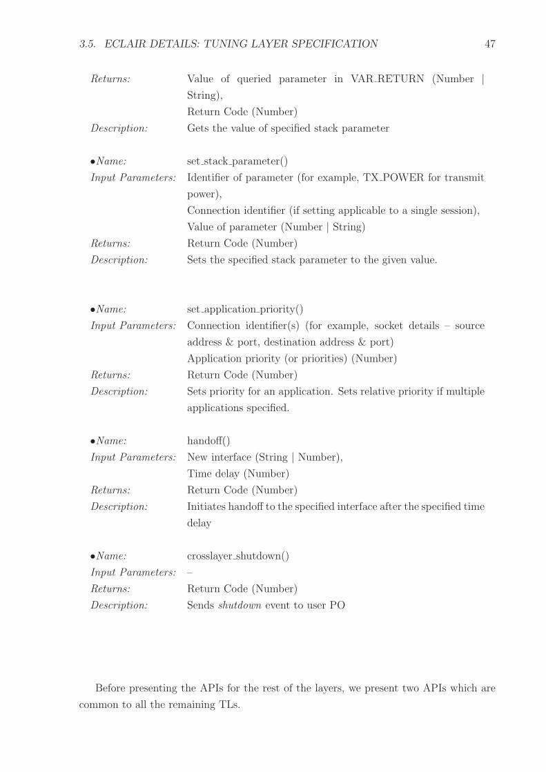
3.5. ECLAIR DETAILS: TUNING LAYER SPECIFICATION 47
Returns: Value of queried parameter in VAR RETURN (Number |
String),
Return Code (Number)
Description: Gets the value of specified stack parameter
•Name: set stack parameter()
Input Parameters: Identifier of parameter (for example, TX POWER for transmit
power),
Connection identifier (if setting applicable to a single session),
Value of parameter (Number | String)
Returns: Return Code (Number)
Description: Sets the specified stack parameter to the given value.
•Name: set application priority()
Input Parameters: Connection identifier(s) (for example, socket details – source
address & port, destination address & port)
Application priority (or priorities) (Number)
Returns: Return Code (Number)
Description: Sets priority for an application. Sets relative priority if multiple
applications specified.
•Name: handoff()
Input Parameters: New interface (String | Number),
Time delay (Number)
Returns: Return Code (Number)
Description: Initiates handoff to the specified interface after the specified time
delay
•Name: crosslayer shutdown()
Input Parameters: –
Returns: Return Code (Number)
Description: Sends shutdown event to user PO
Before presenting the APIs for the rest of the layers, we present two APIs which are
common to all the remaining TLs.

48 CHAPTER 3. ECLAIR: AN EFFICIENT CROSS LAYER ARCHITECTURE
3.5.7 Common TL APIs
The following APIs are common to the TLs of Application, Transport, Network, MAC
and Phy.
•Name: register()
Input Parameters: [ Call back function ],
Event name (String)
Returns: Return Code (Number)
Description: PO registers for event of interest. A callback function is reg-
istered for each event. If no callback function is specified, TL
returns a pointer to the event notification queue
•Name: unregister()
Input Parameters: Event name (String)
Returns: Return Code (Number)
Description: Unregister PO for specified event
3.5.8 Application TL
Application Tuning Layer allows applications to interact with the protocol stack. An
application can specify its QoS requirements using the Application TL. The ATL’s purpose
is to monitor application events and pass the event information to POs within the stack.
Further, the ATL provides APIs to tune applications.
ATL interaction with PO:
Figure 3.9 shows ATL interaction with a PO. Since the ATL is in user-space its interaction
with a PO in kernel-space is through operating system mechanisms. To receive an update
instruction from a PO in kernel-space, the application PO registers with a PO in kernel-
space. This kernel PO is created specifically for application interactions with the kernel-
space. This PO in turn interacts with other POs in the OSS. It serves as an agent for the
applications.
An application can register a call back function for specific events. Alternatively, a
PO can be created externally that registers on behalf of an application. This PO tunes
the application when an event occurs in the stack. Figure 3.9 shows the application TL’s
interface with a PO and an application. Some Application TL APIs are listed below.
•Name: app qos requirements()
Input Parameters: QoS parameters – Bandwidth (Number), Delay (Number),
Losses (Number)
Returns: Return Code (Number)

3.5. ECLAIR DETAILS: TUNING LAYER SPECIFICATION 49
Description: Pass application QoS (Quality of Service) requirements, that is,
bandwidth, delay, losses acceptable, to the cross layer POs.
•Name: get connection cost()
Input Parameters: Interface (String | Number) | Void
Returns: Cost per minute of connection (Number) | Return Code (Num-
ber)
Description: Fetches cost per minute of specified interface (current interface
if input parameter is void)
Applications or POs can use the APIs provided by UTL for accessing other parameters
of the stack. Next, we present the APIs for TCPTL as an example for Transport TL.
(Operating System call)Register
Kernel space
User space
Protocol Optimizer
Application Tuning Layer
Register(function call)
Signal(Operating System call)
Application
Signal(function call)
(function call)Message
Figure 3.9: Application Tuning Layer Interfaces
3.5.9 Transport TL
Transport TL provides components for tuning the transport layer protocols. We present
some example APIs for TCP TL. TCP TL allows query and update of various control data
structures within TCP. The APIs can be used to query or update the values of a specific
TCP flow or all TCP flows. Additional APIs are listed in the Appendix, Section I-1.
For all the APIs, TL implementation ensures correct and fast location of the appro-
priate connection. The TL implements appropriate algorithms for fast location. In the
following, socket identifier means the 4-tuple source address & port, destination address
& port.
TCP TL APIs:
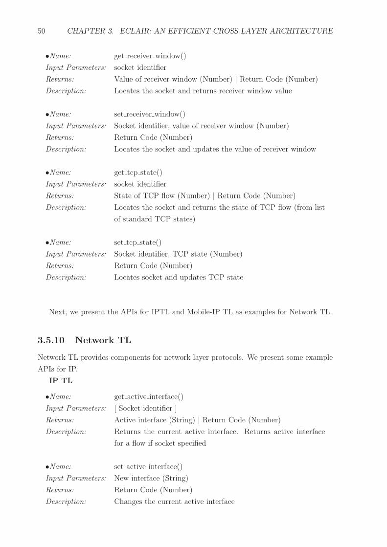
50 CHAPTER 3. ECLAIR: AN EFFICIENT CROSS LAYER ARCHITECTURE
•Name: get receiver window()
Input Parameters: socket identifier
Returns: Value of receiver window (Number) | Return Code (Number)
Description: Locates the socket and returns receiver window value
•Name: set receiver window()
Input Parameters: Socket identifier, value of receiver window (Number)
Returns: Return Code (Number)
Description: Locates the socket and updates the value of receiver window
•Name: get tcp state()
Input Parameters: socket identifier
Returns: State of TCP flow (Number) | Return Code (Number)
Description: Locates the socket and returns the state of TCP flow (from list
of standard TCP states)
•Name: set tcp state()
Input Parameters: Socket identifier, TCP state (Number)
Returns: Return Code (Number)
Description: Locates socket and updates TCP state
Next, we present the APIs for IPTL and Mobile-IP TL as examples for Network TL.
3.5.10 Network TL
Network TL provides components for network layer protocols. We present some example
APIs for IP.
IP TL
•Name: get active interface()
Input Parameters: [ Socket identifier ]
Returns: Active interface (String) | Return Code (Number)
Description: Returns the current active interface. Returns active interface
for a flow if socket specified
•Name: set active interface()
Input Parameters: New interface (String)
Returns: Return Code (Number)
Description: Changes the current active interface

3.5. ECLAIR DETAILS: TUNING LAYER SPECIFICATION 51
•Name: get frag assy timer()
Input Parameters: –
Returns: Current fragment reassembly timer (Number) | Return Code
(Number)
Description: Returns the value of fragmentation reassembly timer
•Name: set frag assy timer()
Input Parameters: Timer value (Number)
Returns: Return Code (Number)
Description: Updates the value of fragmentation reassembly timer
Mobile-IP TL The following APIs have been defined based on the study of Mobile-
IP RFC [59] and the code of Dynamics Mobile-IP implementation [97]. Additional APIs
are listed in the Appendix, Section I-2.
•Name: get registration lifetime()
Input Parameters: –
Returns: Duration (number) | Return Code (Number)
Description: Returns the registration lifetime
•Name: set registration lifetime()
Input Parameters: Duration (number)
Returns: Return Code (Number)
Description: Updates the registration lifetime
•Name: get solicitation rate()
Input Parameters: –
Returns: Rate (number) | Return Code (Number)
Description: Returns the solicitation rate
•Name: set solicitation rate()
Input Parameters: Rate (number)
Returns: Return Code (Number)
Description: Updates the solicitation rate

52 CHAPTER 3. ECLAIR: AN EFFICIENT CROSS LAYER ARCHITECTURE
Next, we present the APIs for 802.11-TL as an example for MACTL.
3.5.11 MAC TL
MAC TL provides components for tuning the transport layer protocols. We present some
example APIs for 802.11-MAC-TL. Additional APIs are listed in the Appendix, Section I-
3. Information about 802.11 is available in reference [33].
802.11 MAC TL
•Name: get contention window()
Input Parameters: –
Returns: Current contention window (Number) | Return Code (Number)
Description: Returns current contention window value
•Name: set contention window()
Input Parameters: Contention Window (Number)
Returns: Return Code (Number)
Description: Sets contention window to specified value
•Name: get rts cts threshold()
Input Parameters: –
Returns: Current RTS/CTS threshold (Number) | Return Code (Number)
Description: Returns current RTS/CTS threshold
•Name: set rts cts threshold()
Input Parameters: RTS/CTS threshold (Number)
Returns: Return Code (Number)
Description: Sets RTS/CTS threshold to specified value
3.5.12 Phy TL
MAC TL provides components for tuning the transport layer protocols. We present some
example APIs for 802.11-Phy-TL. Additional APIs are listed in the Appendix, Section I-4.
802.11 Phy TL
•Name: get transmit rate()
Input Parameters: –
Returns: Current transmit rate | Return Code (Number)
Description: Returns the current transmit rate of the active interface

3.6. OPTIMIZING SUBSYSTEM SPECIFICATION 53
•Name: set transmit rate()
Input Parameters: Transmit rate (Number)
Returns: Return Code (Number)
Description: Sets the transmit rate of the active interface
•Name: get transmit power()
Input Parameters: –
Returns: Current transmit power () | Return Code (Number)
Description: Returns the current transmit power of the active interface
•Name: set transmit power()
Input Parameters: Transmit Power (Number)
Returns: Return Code (Number)
Description: Set the transmit power of the active interface
In this section we described the details about TLs. ECLAIR does not require that all
the TLs be implemented in a system. The cross layer designer can choose to implement
only the required TLs for a system. In the next section we present details about the
Optimizing SubSystem.
3.6 Optimizing SubSystem Specification
3.6.1 Introduction
The Optimizing SubSystem (OSS) contains cross layer feedback algorithms. It consists
of multiple Protocol Optimizers (POs). Each PO contains an algorithm for a cross layer
optimization. For example, a PO would contain the algorithm for modifying the transmit
power based on current wireless environment.
3.6.2 Software Component View
Figure 3.10 shows the software component view of the Optimizing SubSystem (OSS) and
the components with which it interacts.
A PO uses the APIs provided by the TLs to monitor the protocols for events and
modify the protocol behavior. A PO may interact with one or more POs. Further, POs
may interact with each other across the user-kernel boundary.

54 CHAPTER 3. ECLAIR: AN EFFICIENT CROSS LAYER ARCHITECTURE
User TLApplication TL
ApplicationsUser
Transport TL Phy TLMAC TLNetwork TL
Transport Network MAC Phy
ProtocolOptimizer−4 Optimizer−n
ProtocolOptimizer−3
Protocol
Opt
imiz
ing
Sub
Sys
tem
User SpaceKernel Space
ProtocolOptimizer−1 Optimizer−2
Protocol
Figure 3.10: ECLAIR Optimizing SubSystem - Software component view
3.6.3 Optimizing SubSystem – Theory of Operation
Dependencies:
A PO is dependent on the TL and operating system APIs.
Initialization:
POs are initialized by the operating system. Since POs are dependent on TL APIs they
are initialized after initialization of the protocol stack and TLs. On initialization, a PO
registers for one or more events with the TL and waits for event notification from the TL
(see Section 3.5).
Event notification:
The notification to PO could be synchronous or asynchronous. The PO provides a callback
function to the TL for synchronous notification. For asynchronous notification the TL
sends a message to the PO, in a message queue. The PO implements appropriate handler
to receive and process the message.
The event notification contains an event identifier and value of the protocol data
structure that caused the event.
Cross Layer algorithm:
Based on the cross layer event notification, appropriate cross layer algorithm is executed
within the event handler in the PO.

3.6. OPTIMIZING SUBSYSTEM SPECIFICATION 55
The cross layer algorithm determines the layers that need to be adapted. Appropriate
TL API is invoked to read the control data structures of the protocols that are to be
adapted. The algorithm determines the new values for these control data structures.
Appropriate TL API is invoked to update the control data structures with the new values
so as to change the protocol behavior.
Using TL API:
The PO invokes the generic API of the target protocol’s TL for reading or updating
the target protocol’s data structures. The generic API in turn invokes the implementa-
tion specific API. This implementation specific function call locates the appropriate data
structure and reads and returns or updates the requisite protocol data structure.
For protocols with multiple flows, a PO may specify update to a specific flow, within
the protocol. An update specified without a flow specification, implies an update to all
the flows in the protocol.
Event processing :
The PO accepts and processes one event at a time. In case of asynchronous notification
while an event is being processed, the other events received are queued.
Error handling:
In case of error returned by the TL, if debug mode is on, the PO logs the error number
and the API invoked to the error log. In case fatal error is returned by the TL, the PO
unregisters from all TLs. The PO remains unregistered till the PO is reinitialized.
Unload, cleanup:
A PO is unloaded when a fatal error occurs or on system shutdown. Unload means that
the PO unregisters from all TLs and remains in that state till the system is rebooted.
When a PO is unloaded, it:
• unregisters from all the TLs
• deallocates all its data structures
• aborts any procedure in progress
• logs the reason for unload
Disabling Cross Layer:
In case of a cross layer shutdown event from the user, the PO unloads. The shutdown
event is generated by the user. The user PO registers with all the TLs at the time of OSS
initialization. The user PO sends this event to all the TLs. The TLs in turn send this
event to all the POs registered for any event. Subsequent to delivering the event to the
POs, the TLs also unload. The cross layer system can be enabled again by rebooting.
Above we described the working of a PO. Next, we specify the functions that a PO
must implement.

56 CHAPTER 3. ECLAIR: AN EFFICIENT CROSS LAYER ARCHITECTURE
3.6.4 Procedures within PO
A PO implements the following procedures:
• Cross layer feedback procedure: This procedure contains the algorithm that de-
termines adaptation of protocols. Its execution is triggered whenever an event is
delivered to the PO.
• Event handler: is invoked when an event is delivered to the PO. It is called by the
TL for delivering events to the PO, when registered as a callback function. The
event handler invokes the appropriate cross layer adaptation procedure. A single
event handler may handle multiple events.
• Register procedure: registers the event handler for each event, with the TL.
• Unregister procedure: unregisters the PO from the TL, for a particular event. The
function determines the event for which the PO should unregister. This procedure
is called from the error handler (see below).
• Log procedure: logs the TL API invoked and the error returned by the TL API.
This procedure is invoked only if debug is enabled on the system.
• Error handler: is invoked when the TL API returns an error. In case of fatal errors,
the error handler invokes the unregister function of the PO. In case debug is enabled,
the error handler also invokes the log procedure.
In the sections above, we presented the working of ECLAIR and the architectural
specifications for the components of ECLAIR. In the next section, we summarize the
salient features of ECLAIR.
3.7 ECLAIR Salient Features
The salient features of ECLAIR are as follows:
• User Tuning Layer : Besides the layer specific TLs, ECLAIR also provides a User
Tuning Layer (UTL). UTL allows a device user or an external entity, for example,
a distributed algorithm or a base station, to tune the device behavior.
• Event Notification: TLs provide APIs which are used by the POs to register for
interesting events at a layer. For example, TCP can register for handover completion
event at the Mobile-IP layer.

3.8. SUMMARY 57
• Cross layer shutdown: The POs and TLs are architected in such a way that in case
of severe errors, the problematic PO will not carry out any further adaptations.
Further, the user can disable the entire cross layer adaptation system, during run-
time.
• Support for seamless mobility : ECLAIR can be used to enable seamless mobility [14]
on the mobile devices. ECLAIR provides TLs for multiple protocols within a layer.
A PO can be created that monitors and controls multiple wireless interfaces. This
PO can adapt protocols as the device moves across heterogeneous networks and thus
enable seamless mobility across these networks.
3.8 Summary
In this chapter we presented our cross layer feedback architecture – ECLAIR. We also
illustrated the working of ECLAIR using some example POs. We presented the working,
internal details and architectural specification of ECLAIR components, that is, Tuning
Layers (TLs) and Optimizing Sub-System (OSS).
In the next chapter we describe an implementation (Receiver Window Control) using
ECLAIR and validate it through experiments over Ethernet and Wireless LAN.

58
This page has been intentionally left blank

Action is eloquence
- William Shakespeare
Chapter 4
ECLAIR Validation
In the earlier chapters we presented the motivation for cross layer feedback, the need
for a cross layer feedback architecture, and presented our architecture – ECLAIR. In this
chapter we validate ECLAIR. We use Receiver Window Control (RWC) [69, 54, 66] as
a running example for explaining ECLAIR implementation and validation. In the next
chapter we also use this implementation for a quantitative comparison of ECLAIR RWC
performance with a user space implementation of RWC [54], and architectures proposing
modification to the protocol stack. Before presenting the implementation details, we
present an overview of RWC below.
4.1 Receiver Window Control
Users can provide useful feedback to improve the performance of the stack or the user
experience [64, 66]. For example, a user may want a file download to complete faster than
another simultaneous download on the device. One method of controlling an application’s
(which uses TCP) bandwidth share, on a receiving device, is through manipulation of
the receiver window of its TCP connection. This approach is called Receiver Window
Control [54, 66].
TCP uses congestion and flow control mechanisms to avoid swamping the network or
the receiver [52, 61, 70]. The receiver reflects its receive buffer status in the advertised
window field in the acknowledgments to the sender. When the sender is not congestion
window limited, the receiver can control the transmission rate of the sender through the
advertised window.
59

60 CHAPTER 4. ECLAIR VALIDATION
We note that throughput for a TCP connection is decided by the receiver window
setting and the corresponding bandwidth-delay product [70]. In case of multiple flows,
each having a different bandwidth-delay product, each of the flows will have a different
optimum receiver window or advertised window(awnd). This property of awnd’s relation
to the bandwidth-delay product can be exploited to intentionally make some of the TCP
sessions get lower throughput, and thus dynamically control the application throughput.
We call this approach Receiver Window Control(RWC). This assumes that total actual
receiver buffer space is large enough to allow manipulation(increase or decrease) of the
awnd values for the different sessions.
The current TCP implementations have fixed receive buffer sizes for all applications.
Application level APIs are available, that allow an application to set its receiver buffer at
the start of a connection [78]. However, once set it cannot be modified to reflect changes
in application priorities.
The intuitive benefit of RWC can be seen from the following example: A user is
running multiple downloads on a wireless device. The user increases the priority of one
of the downloads. Through RWC, this higher priority is mapped to an increased awnd for
the higher priority download . On the other hand, the awnd of the lower priority download
is decreased. This would increase the throughput of the higher priority download. This
control is dynamic and is invoked whenever the user changes application priorities. We
now present the RWC algorithm [66].
4.1.1 RWC Algorithm
Let, n be the number of applications.
B = Bandwidth available to MH on the bottleneck link. B is shared among the n
applications running on the MH. B is assumed to be constant.
R = rtt for all the applications on the MH and is assumed to be constant.
The RWC algorithm is presented in Figure 4.1. The application priority number xi
is used for relative ordering of the applications and actual numbers have no significance.
The ratio of the priority numbers is used in the algorithm.
We explain the RWC algorithm through an example. Consider three applications. Let,
A = 30, x1 = 1, x2 = 1, x3 = 1. Thus (from Figure 4.1) initially awnd1 = 10, awnd2 =
10, awnd3 = 10. After user feedback, let x1 = 2 (x1, x2 are not changed i.e. x2 = 1 and
x3 = 1). Now, from Figure 4.1, awnd1 = round(2
4∗ 30) = 15 awnd2 = round(1
4∗ 30) = 8,
awnd3 = 30 − (15 + 8) = 7. Thus, it can be seen that RWC increases awnd for higher
priority applications and decreases awnd for lower priority applications.
As the next step for validating ECLAIR we conducted some simulations of RWC using
ns-2 [57]. These simulations help us determine the benchmarks for RWC using ECLAIR.

4.2. RWC SIMULATIONS 61
Events
UserFeedback: User changes priority of applications
Initialization
n = number of applications
B = available bandwidth // constantR = rtt // constantA = B × R
awndi = default advertised window // initially all equalxi = 1 // application priority; initially all equal
Function CallsReceiverWindowControl()
cum awnd = 0;// User changes priority of applications; xi is changedfor i = 0 to i < n − 1 do
awndi = round( xi∑ n−1
j=0xj
∗ A)
cum awnd = cum awnd + awndi
end forawndn−1 = A − cum awnd
Figure 4.1: Receiver Window Control
4.2 RWC Simulations
Fixed Host (FH)
2 Mbps, 60ms
N1 100 Mbps, 4ms
100 Mbps, 4msN2
N3 N4
Fixed Host (FH)
Mobile Host (MH)
Figure 4.2: RWC: Simulation setup
The simulation setup is shown in Figure 4.2. Two ftp1 flows, f1 and f2, were run from
the two fixed hosts, N1 and N2 respectively. The mobile host (MH) is the receiver. User
feedback was simulated by setting the window (window underscore) parameter of the
TCP senders on N1 and N2, 5 seconds after start of simulation. The initial priorities were
assumed to be: x1 = 1 and x2 = 1. For the simulation set-up A = 32 packets. Thus from
Figure 4.1, awnd1 = 16 and awnd2 = 16. After feedback, let x1 = 2 and x2 = 1. Hence,
from Figure 4.1, awnd1 = 11 and awnd2 = 21. The window parameter of the senders on
N1 and N2 were set to these values, respectively.
One set of simulations was done assuming no losses on the links. A second set was
done, assuming a loss of 0.1% on the link N3-N4. Each simulation run was of 9 seconds
duration.
1File Transfer Protocol

62 CHAPTER 4. ECLAIR VALIDATION
4.2.1 RWC Simulation Observations
• Scenario 1: No loss with no RWC – (Figure 4.3(a)). As expected the throughput
of both f1 and f2 is equal, each ≈ 1 Mbps.
• Scenario 2: No loss with RWC – (Figure 4.3(b)) the throughput for f1 increases to
≈ 1.31 Mbps (increase by 31%) and that for f2 decreases to ≈ 0.69 Mbps (decrease
by 31%).
500
550
600
650
700
750
800
850
900
950
1000
1050
1 2 3 4 5 6 7 8 9
thru
put(
kbps
)
time (sec)
Thruput vs Time
f1 (no RWC)f2 (no RWC)
(a) Scenario 1: No loss with no RWC
500
600
700
800
900
1000
1100
1200
1300
1400
1 2 3 4 5 6 7 8 9
thru
put(
kbps
)
time (sec)
Thruput vs Time
f1 (no RWC)f2 (RWC)
(b) Scenario 2: No loss with RWC
400
500
600
700
800
900
1000
1100
1 2 3 4 5 6 7 8 9
thru
put(
kbps
)
time (sec)
Thruput vs Time
f1 (no RWC)f2 (no RWC)
(c) Scenario 3: 0.1% loss with no feedback
400
500
600
700
800
900
1000
1100
1200
1 2 3 4 5 6 7 8 9
thru
put(
kbps
)
time (sec)
Thruput vs Time
f1 (no RWC)f2 (RWC)
(d) Scenario 4: 0.1% loss with RWC
Figure 4.3: RWC: Simulation results
• Scenario 3: 0.1% loss with no RWC – (Figure 4.3(c)) shows the throughput of both
the applications under lossy link conditions. The variations in throughput are due
to the random losses. However, the throughput of both the flows is approximately
equal.
• Scenario 4: 0.1% loss with RWC – (Figure 4.3(d)) user feedback has the effect of
increasing the throughput for f1, even though there are some packet losses.
In the previous sections, we discussed the RWC algorithm, RWC simulations and
observations. We now describe the prototype implementation of RWC using ECLAIR.

4.3. RECEIVER WINDOW CONTROL IMPLEMENTATION USING ECLAIR/LINUX63
4.3 Receiver Window Control Implementation using
ECLAIR/Linux
The high level design of RWC using ECLAIR is presented in Chapter 3, Section 3.4.1
(Figure 3.3). Next we present the implementation details.
4.3.1 Receiver Window Control Implementation Details
First we present some of the internal details of the Linux TCP/IP kernel which are relevant
for Receiver Window Control implementation using ECLAIR. We chose Linux since its
source code is freely available and modifiable.
Figure 4.4 shows the relevant data structures in sock.h. The numbers on the left
identify the relevant code. tcp opt (line number 1) is TCP’s control data structure. sock
1 struct tcp_opt {
.
.
/* Maximal window to advertise */
2 __u32 window_clamp;
/* Current window clamp */
3 __u32 rcv_ssthresh;
.
}
4 struct sock {
.
.
5 union {
6 struct tcp_opt af_tcp;
.
.
}
}
Figure 4.4: /usr/src/linux-2.4/include/net/sock.h source code snippet
(line number 4) is the socket data structure. Line numbers 2 and 3 show window clamp
and rcv ssthresh which are used for controlling the advertised window in TCP. We
identified these data structures by studying the TCP implementation in Linux kernel
2.4.x [101]. For browsing the Linux kernel code, we used source code browsing tools such
as cscope [94], cbrowser [92] and the Linux Cross Reference website [93].
Figure 4.5 shows the call flow of our implementation using ECLAIR. The current
implementation has largely TL functionality only. In this prototype the RWC calculation
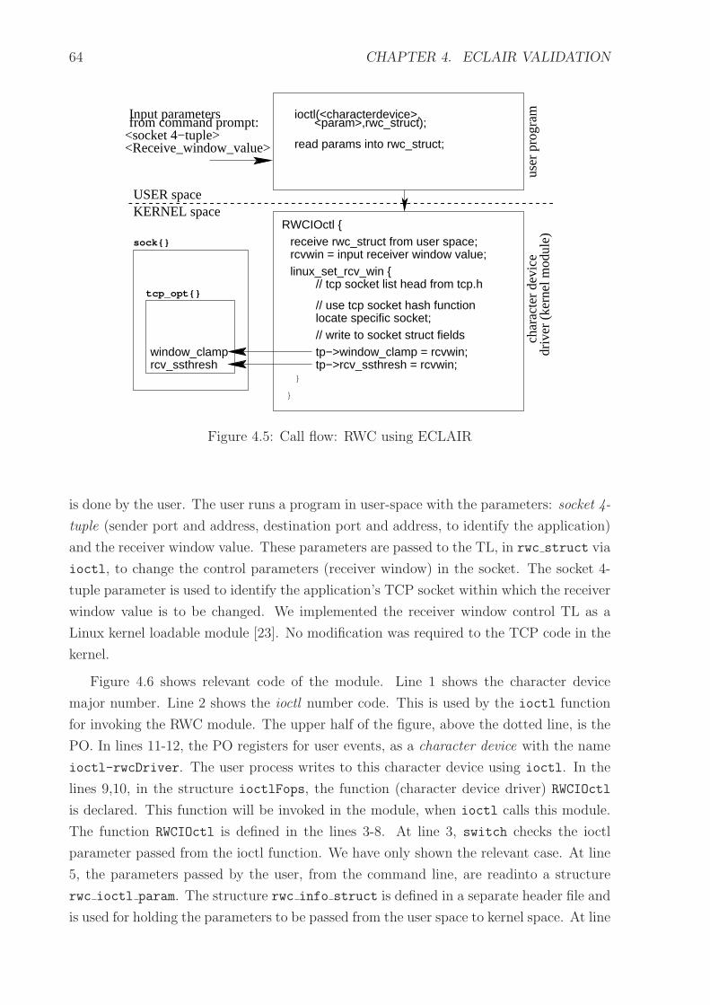
64 CHAPTER 4. ECLAIR VALIDATION
tcp_opt{}
sock{}
Input parametersfrom command prompt:
<Receive_window_value>
user
pro
gram
driv
er (
kern
el m
odul
e)
USER spaceKERNEL space
ioctl(<characterdevice>, <param>,rwc_struct);
read params into rwc_struct;
RWCIOctl {receive rwc_struct from user space;
char
acte
r de
vicercvwin = input receiver window value;
<socket 4−tuple>
}
}
linux_set_rcv_win {// tcp socket list head from tcp.h
rcv_ssthreshwindow_clamp
// write to socket struct fieldstp−>window_clamp = rcvwin;tp−>rcv_ssthresh = rcvwin;
locate specific socket;// use tcp socket hash function
Figure 4.5: Call flow: RWC using ECLAIR
is done by the user. The user runs a program in user-space with the parameters: socket 4-
tuple (sender port and address, destination port and address, to identify the application)
and the receiver window value. These parameters are passed to the TL, in rwc struct via
ioctl, to change the control parameters (receiver window) in the socket. The socket 4-
tuple parameter is used to identify the application’s TCP socket within which the receiver
window value is to be changed. We implemented the receiver window control TL as a
Linux kernel loadable module [23]. No modification was required to the TCP code in the
kernel.
Figure 4.6 shows relevant code of the module. Line 1 shows the character device
major number. Line 2 shows the ioctl number code. This is used by the ioctl function
for invoking the RWC module. The upper half of the figure, above the dotted line, is the
PO. In lines 11-12, the PO registers for user events, as a character device with the name
ioctl-rwcDriver. The user process writes to this character device using ioctl. In the
lines 9,10, in the structure ioctlFops, the function (character device driver) RWCIOctl
is declared. This function will be invoked in the module, when ioctl calls this module.
The function RWCIOctl is defined in the lines 3-8. At line 3, switch checks the ioctl
parameter passed from the ioctl function. We have only shown the relevant case. At line
5, the parameters passed by the user, from the command line, are readinto a structure
rwc ioctl param. The structure rwc info struct is defined in a separate header file and
is used for holding the parameters to be passed from the user space to kernel space. At line

4.3. RECEIVER WINDOW CONTROL IMPLEMENTATION USING ECLAIR/LINUX65
1 #define IOCTL_MAJOR 250
2 #define IOCTL_GETVALUE 0x0001
...
3 static int RWCIOctl(...)
{
...
switch( cmd ) {
4 case IOCTL_GETVALUE:
5 rwc_ioctl_param = (struct rwc_info_struct *) arg;
// copy socket 4-tuple to socket_info
6 socket_info.s_addr =
rwc_ioctl_param->in_ip_addr.s_addr;
...
7 rwc_window = rwc_ioctl_param->rwc_window;
// TCP TL function
8 linux_set_recv_win (socket_info, rwc_window);
...
}
9 static struct file_operations ioctlFops = {
...
10 ioctl: RWCIOctl, /* ioctl */
};
11 static int __init IoctlRWCInit(void)
{
printk(KERN_ERR "TCP RWC func load.\n");
12 if(register_chrdev(IOCTL_MAJOR,
"ioctl-rwcDriver", &ioctlFops) == 0) {
...
};
printk("ioctl: unable to get major %d\n",IOCTL_MAJOR);
return( -EIO );
}
----------------------------------------------------------------
13 linux_set_recv_win (socket_info, rwc_window)
{
14 // locate socket using socket_info and copy of tcp_hashfn
15 struct tcp_opt *tp = &(sk->tp_pinfo.af_tcp);
16 lock_sock(sk);
17 tp->window_clamp = rwc_window;
18 tp->rcv_ssthresh = rwc_window;
19 release_sock(sk);
}
Figure 4.6: rwc user.c source code snippet. RWC PO and TL

66 CHAPTER 4. ECLAIR VALIDATION
8, the parameters socket 4-tuple (sender address and port, destination address and port),
and receiver window value are passed to the TCP TL function linux set recv win. The
function linux set recv win is defined from lines 13-19. At line 14, the relevant socket
is located using tcp hashfn. Code for this function is available in the Linux kernel source
code file /usr/src/linux-2.4/net/ipv4/tcp ipv4.c. At line 15, the tcp information
structure is extracted from the socket structure. From lines 16-19, the socket located
above is locked for writing, tcp structure’s window clamp and rcv ssthresh is updated
to set the receiver window value and finally the socket lock is released.
Next, we present the details of the RWC-ECLAIR experiments over wireline and
WLAN. A detailed evaluation of ECLAIR overheads is presented in Chapter 5.
4.4 RWC Experiments
4.4.1 Experiments over Ethernet LAN
The first set of experiments were done on Ethernet LAN to rule out any variations due
to the wirelss connection. The aim of these experiments was to do a basic test that the
RWC implementation is functioning correctly. Figure 4.7 shows the experimental setup.
All the machines were on the IIT Bombay campus LAN. The link N3-N4 bandwidth is 1
Mbps. Two flows Flow 1 and Flow 2 were started from N1 (cygnus) and N2 (gitanjali),
respectively, to N4 (sarus). The flows were started simultaneously in the background
using wget on N4. A file of appox. 9MB was transfered from both N1 and N2 using http.
Receiver Window Control was implemented on the node N4.
Figure 4.8(a) shows the results when RWC was not invoked. Both the flows had
almost equal throughput. The variations are due to competing traffic on the network.
Figure 4.8(b) shows the results when RWC was manually invoked at about 8 seconds. We
invoked RWC with a receiver window size of 1450 bytes, on Flow 1. Figure 4.8(b) shows
that the throughput of Flow 1 decreases while that of Flow 2 increases. The throughput
of Flow 1 increases slightly after the file transfer of Flow 2 ends.
The results are as expected and validate our implementation of Receiver Window
Control. Subsequent to the Ethernet LAN experiments we carried out experiments over a
802.11 wireless network. The wireless experiment setup and results are presented below.
4.4.2 Experiments over 802.11 Wireless Connection
Figure 4.9 shows the experimental setup. For our experiments we used a Air Premier D-
Link Enterprise 2.4GHz Wireless Access Point – DWL-1000AP+ (managed mode), and
D-link 520+ Wireless PCI Adapter (2.4 GHz) [96] on the desktop (Intel Pentium4 CPU,

4.4. RWC EXPERIMENTS 67
N1
N2
N3 N41 Mbps
Fixed Host (FH)
Fixed Host (FH)gitanjali.cse.iitb.ac.in
Mobile Host (MH)sarus.cse.iitb.ac.in
100 Mbps
1 Mbps
cygnus.it.iitb.ac.in
Figure 4.7: RWC: Experiment setup
0
100
200
300
400
500
600
700
800
900
1000
1100
0 5 10 15 20 25
thru
put (
Kbp
s/se
c)
time (sec)
wget session throughput graphs
Flow 1 no RWCFlow 2 no RWC
(a) No RWC
150
200
250
300
350
400
450
500
550
600
650
0 2 4 6 8 10 12 14 16 18
thru
put (
Kbp
s)
time (sec)
wget session throughput graphs
Flow 1 with RWCFlow 2 no RWC
(b) RWC: Receiver Window value = 1450 bytes,invoke time = 8 sec
Figure 4.8: Receiver Window Control experiments over wireline (Ethernet)
1.90GHz, 256 MB RAM, 256KB cache) which had the RWC implementation. To match
the environment characteristics, we set the sensitivity of the WLAN card to 60 using the
script available with the driver package [90, 91]. Sensitivity is the lowest signal level for
which the hardware will consider received packets usable. Sensitivity is the threshold set
for Received Signal Strength Indicator (RSSI). This is set based on the average noise level
to avoid reception of noise. The card sensitivity was set to 60 on a scale of 255 (maximum
value). We used the default MTU2 of 1500. For our experiments:
• We ran two wget 3 http 4 sessions from MH to FH1 and FH2. The file size down-
loaded was 2MB each.
• We invoked RWC from the command prompt during the http transfer, with different
receive window values.
2Maximum Transmission Unit3Wget is a network utility to retrieve files from the Web using http and ftp4Hyper Text Transfer Protocol

68 CHAPTER 4. ECLAIR VALIDATION
Fixed host 1 (FH1)
Fixed host 2 (FH2)
KReSIT department LAN100 Mbps
WLAN 802.11b
Desktop with WLAN cardwith RWC implementation
(MH)
RTT ~ 3 ms
(typical ~ 8Mbps)
Access pointManaged mode
Figure 4.9: RWC: Experiment setup
• We carried out four experiments. Each experiment was repeated 3 times.
– In the first experiment, RWC was not invoked.
– In the other three experiments, RWC was invoked with receiver window values
of 2KB, 1KB and 0.5KB. For each receiver window value, RWC was invoked
at 1, 2 and 5 seconds.
We have shown representative results in Figure 4.10. The graphs of the other runs are
similar. We have not taken averages of the results, since there were wide fluctuations in
throughput due to the wireless medium.
Table 4.1 shows the mean and standard deviation of the throughput for Flows 1 and
2 across various runs.
RWC Experiment Observations
For the experimental setup the approximate bandwidth-delay product is 3KB. (8000/8
KBps * 3/1000 sec, see Figure 4.9). Thus to throttle a sender the receiver window should
be less than 3KB. Since network packet losses are expected in a WLAN, we started with
a receiver window of 2KB.

4.4. RWC EXPERIMENTS 69
200
300
400
500
600
700
800
0 1 2 3 4 5 6 7 8 9
thru
put (
kbyt
es/s
ec)
time (sec)
Flow 1 (no RWC)Flow 2 (no RWC)
(a) No RWC
0
100
200
300
400
500
600
700
0 2 4 6 8 10 12
thru
put (
kbyt
es/s
ec)
time (sec)
Flow 1 (no RWC)Flow 2 (RWC)
(b) RWC: Receiver Window value = 2KB, invoketime = 1 sec
0
100
200
300
400
500
600
700
0 2 4 6 8 10 12
thru
put (
kbyt
es/s
ec)
time (sec)
Flow 1 (no RWC)Flow 2 (RWC)
(c) RWC: Receiver Window value = 2KB, invoketime = 2 sec
0
100
200
300
400
500
600
700
800
0 1 2 3 4 5 6 7 8 9
thru
put (
kbyt
es/s
ec)
time (sec)
Flow 1 (no RWC)Flow 2 (RWC)
(d) RWC: Receiver Window value = 2KB, invoketime = 5 sec
0
100
200
300
400
500
600
700
800
0 10 20 30 40 50 0 10 20 30 40
thru
put (
kbyt
es/s
ec)
time (sec)
Flow 1 (no RWC)Flow 2 (RWC)
(e) RWC: Receiver Window value = 1KB, invoketime = 5 sec
0
100
200
300
400
500
600
700
800
00:00 01:00 02:00 03:00 04:00 05:00 06:00 07:00 08:00
thru
put (
kbyt
es/s
ec)
time (min:sec)
Flow 1 (no RWC)Flow 2 (RWC)
(f) RWC: Receiver Window value = 0.5KB, in-voke time = 5 sec
Figure 4.10: Receiver Window Control experiments over WLAN (802.11)
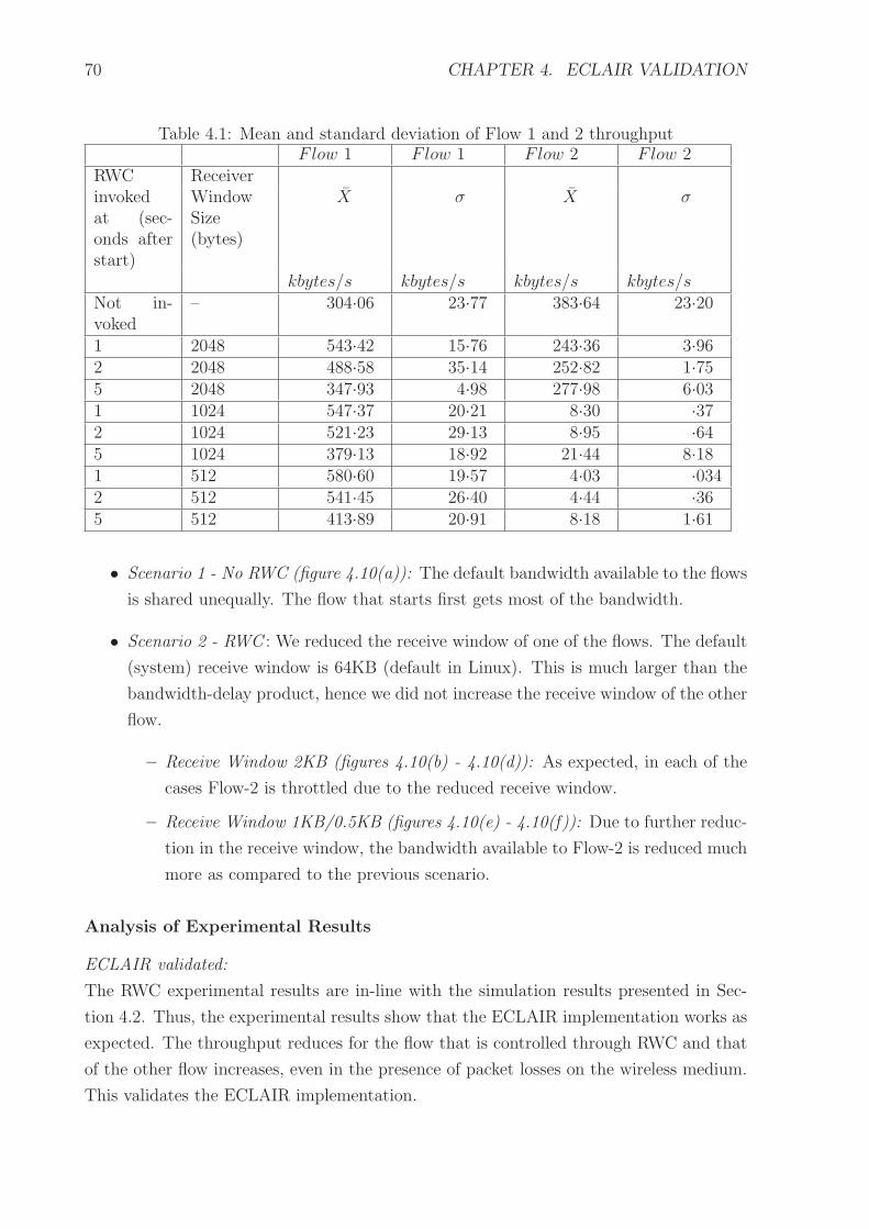
70 CHAPTER 4. ECLAIR VALIDATION
Table 4.1: Mean and standard deviation of Flow 1 and 2 throughputFlow 1 Flow 1 Flow 2 Flow 2
RWC Receiverinvokedat (sec-onds afterstart)
WindowSize(bytes)
X σ X σ
kbytes/s kbytes/s kbytes/s kbytes/sNot in-voked
– 304·06 23·77 383·64 23·20
1 2048 543·42 15·76 243·36 3·962 2048 488·58 35·14 252·82 1·755 2048 347·93 4·98 277·98 6·031 1024 547·37 20·21 8·30 ·372 1024 521·23 29·13 8·95 ·645 1024 379·13 18·92 21·44 8·181 512 580·60 19·57 4·03 ·0342 512 541·45 26·40 4·44 ·365 512 413·89 20·91 8·18 1·61
• Scenario 1 - No RWC (figure 4.10(a)): The default bandwidth available to the flows
is shared unequally. The flow that starts first gets most of the bandwidth.
• Scenario 2 - RWC : We reduced the receive window of one of the flows. The default
(system) receive window is 64KB (default in Linux). This is much larger than the
bandwidth-delay product, hence we did not increase the receive window of the other
flow.
– Receive Window 2KB (figures 4.10(b) - 4.10(d)): As expected, in each of the
cases Flow-2 is throttled due to the reduced receive window.
– Receive Window 1KB/0.5KB (figures 4.10(e) - 4.10(f)): Due to further reduc-
tion in the receive window, the bandwidth available to Flow-2 is reduced much
more as compared to the previous scenario.
Analysis of Experimental Results
ECLAIR validated:
The RWC experimental results are in-line with the simulation results presented in Sec-
tion 4.2. Thus, the experimental results show that the ECLAIR implementation works as
expected. The throughput reduces for the flow that is controlled through RWC and that
of the other flow increases, even in the presence of packet losses on the wireless medium.
This validates the ECLAIR implementation.

4.5. SUMMARY 71
Differences between experimental and simulation results:
There are some differences between the experimental and simulation results. The differ-
ences and the reason for the difference is as follows: (1) In case of simulation, we had run
a continuous transfer using ftp and stopped the simulation after 9 seconds. In case of
the experiment, we transferred a file using wget and stopped the experiment after both
the transfers (Flow-1 and Flow-2) had completed. (2) When RWC is not invoked, the
simulation shows an equal distribution of bandwidth between the two flows. In case of
the experiment on WLAN, due to the characteristics of the wireless interface and environ-
ment, the flow that starts first gets most of the bandwidth. (3) In the experiment, after
RWC is invoked, throughput of the controlled flow remains low even after the uncontrolled
flow completes the file transfer. This is because of the way we have implemented RWC –
we do not reset the value of the receiver window to the default of 64KB. It can be seen
that the differences between experimental and simulation results are not significant and
hence do not impact the validation result, stated above.
4.5 Summary
In this chapter we presented our prototype ECLAIR implementation for receiver window
control. We explained the details of the implementation using code snippets. We validated
the prototype implementation by experiments over a WLAN.
The RWC prototype is sufficient to validate ECLAIR, due to the following: (1) It
shows that a protocol’s (TCP’s) behavior can be modified by manipulating the control
data structure. Similarly, the modification of protocol behavior can be done for protocols
of other layers also. (2) Although, the input in this prototype is from the user, the input
can easily be provided by any other PO that needs to modify TCP behavior.
In the next chapter we evaluate ECLAIR.

72
This page has been intentionally left blank

There is nothing either good or bad, but thinking makes it so
- William Shakespeare
Chapter 5
ECLAIR Evaluation
In the previous chapter we discussed the implementation of ECLAIR and its vali-
dation through an illustrative example – RWC. This chapter has four parts – metrics
definition, qualitative evaluation, quantitative evaluation and overhead measurement. In
Section 5.1, we identify a set of metrics for evaluating a cross layer architecture against
the design goals defined in Chapter 2. In Section 5.2, we use these metrics to qualitatively
compare ECLAIR with the other cross layer feedback approaches which were presented
in Chapter 2. In Section 5.3, we quantitatively compare ECLAIR and user-space [54] im-
plementations of Receiver Window Control (RWC). In Section 5.4, we measure ECLAIR
overheads by instrumenting the Linux kernel, and compare it with user-space architecture
and architectures which propose modification to the protocol stack.
5.1 Evaluation Metrics
In Section 2.5 we stated that the design goals for a cross layer architecture are efficiency,
maintainability, minimum intrusion, portability and any to any layer communication.
Metrics are essential to evaluate a cross layer architecture against these goals. Below
we propose metrics for each of these design goals. The metrics are classified into two
categories – efficiency and maintainability.
For any-any layer communication, a subjective evaluation is sufficient to determine
whether an architecture supports it or not. Hence, no specific metric is required for this
design goal.
73

74 CHAPTER 5. ECLAIR EVALUATION
5.1.1 Efficiency Metrics
We define efficiency as runtime and static efficiency. An architecture A1 has more run-time
efficiency than an architecture A2, if A1 requires lesser computing resources at run-time as
compared to A2. Similarly, architecture A1 has more static efficiency than an architecture
A2, if it requires lesser static resources as compared to A2.
Cross layer feedback is essentially a modification to the protocol stack. The intent is
to enhance performance of the stack by reading information from a layer, interpret that
information and effect a change at another layer. However, effecting cross layer feedback
entails the overhead of running additional instructions or programs, in the kernel or user-
space. In light of this, we define the following as the primary performance measures for
efficiency:
• Time overhead: This is the CPU cycles or execution time required
• Space overhead: This has two components: (1) the run-time memory required by
the cross layer algorithm because of the architecture, and (2) the static footprint of
the cross layer implementation.
• User-kernel crossing: This is the number of times user-kernel boundary needs to be
crossed during execution.
User-kernel crossing could contribute significantly to the run-time overhead of cross
layer feedback. Hence, we also consider the number of user-kernel crossings as an
important efficiency metric. User-kernel crossing is an important metric since it
requires a significant number of CPU cycles for switching from user to kernel mode.
Any system call requires switching from user to kernel mode. This typically requires
the system call library wrapper function to issue a software-interrupt. Subsequent
to this copying of data from user-space to kernel-space is required for parameter
passing. Similarly, copying from kernel to user-space is required for passing values
to the user-space. System call processing is explained in detail in reference [13].
• Data path delay: This is the delay introduced in the data path of the stack, due to
cross layer feedback.
Data path is the sequence of functions within the protocol stack which are concerned
only with sending and/or receiving packets. Data path delay means the time delay
on the data path. Data path delay would include a whole or part of time overhead
and user-kernel crossing overhead of a cross layer feedback mechanism. However,
since it directly impacts the throughput of the stack, we list it as an independent
efficiency metric.

5.1. EVALUATION METRICS 75
5.1.2 Maintainability Metrics
Maintainability is a measure of the ease with which a system can be changed or en-
hanced [62]. There is no direct means of measuring maintainability. One of the indi-
rect measures is the time taken to change a system. However, this can be done only
when the system has been deployed. For predicting maintainability at the architecture
level, architecture evaluation techniques such as Architecture-level Modifiability Analysis
(ALMA) [9] or Software Architecture Analysis Method for Evolution and Reusability [51]
can be used. Both these methods propose a scenario based analysis of the architectures for
maintainability. A scenario describes a change that may be required to the system. The
changes required to the various components for implementing the scenario are determined.
The overall impact is assessed to determine the architecture’s maintainability.
For a cross layer feedback architecture maintainability can determined by assessing
the capability of the architecture to support rapid prototyping, minimum intrusion and
portability (Section 2.5).
Rapid Prototyping Metric
Rapid prototyping, as the name implies, should allow introduction of new cross layer feed-
back algorithms or changes to the existing cross layer algorithms with minimal changes
to the system. The effort required to add or modify a cross layer optimization, that is,
number of changes required to the protocol stack and number of changes required to the
cross layer system serve as a measure for rapid prototyping.
Degree of Intrusion Metric
Degree of intrusion can be measured by the number of changes required within the existing
protocol stack, to implement a cross layer optimization.
Assume, x changes are required to the existing stack to implement a cross layer op-
timization for architecture A1 while y changes are required for the same optimization if
architecture A2 is used. If the changes x and y are of similar nature, then if y < x, A2 has
lesser intrusion than A1. For example, if Receiver Window Control is implemented using
CLASS [79], then the number of changes required to the protocol stack will be higher as
compared to the case when ECLAIR is used. Thus, the degree of intrusion of ECLAIR is
less than that of CLASS.
Portability Metric
Portability can be measured by the number of changes required within a cross layer
implementation to port it to another operating system. Portability is high if porting
requires minimum changes to the cross layer optimization.

76 CHAPTER 5. ECLAIR EVALUATION
We believe that the above metrics are sufficient to evaluate any cross layer architecture.
We use these metrics to evaluate ECLAIR. In the next section, we carry out a qualitative
comparison of ECLAIR with the other cross layer feedback mechanisms.
5.2 Qualitative Evaluation
In this section we do a qualitative comparison of ECLAIR with the other cross layer
feedback approaches. Details about the cross layer approaches have been presented in
Chapter 2. We exclude Cross Layer Manager [17] from the evaluation since sufficient
details about the architecture are not available. For each of the approaches we discuss
the features which are relevant for a particular metric. We then rank each approach.
Ranking order: Rank 1 for an approach means that approach is the best as compared to
others, for a particular metric.
5.2.1 Efficiency Evaluation
Recall that the metrics for efficiency are: time overhead, space overhead, user-kernel
crossing and data-path delay (Section 5.1.1).
Time Overhead Evaluation
Here we analyze the time overhead that a cross layer approach would place on the system.
Metric:
As stated in Section 5.1.1, time overhead means the CPU cycles or execution time required.
Analysis:
We analyze the mechanism for event notification and the protocol adaptation technique.
We assume that the time taken by the adaptation algorithm, that is, determination of the
actual adaptation for a protocol would be similar for all the approaches. Hence we do not
include this for the evaluation. Table 5.1 shows the time overhead evaluation. Each row
shows an architecture, factors contributing to time overhead in that architecture, and a
relative rank for the architecture.
Key observations:
ISP [81] has the least time overhead. Since, it passes event information in the packet
header and it does not require much processing time for event creation and cross layer
feedback. Further, cross layer event processing is tightly integrated with the packet pro-
cessing.
ECLAIR rank is 3, since it needs CPU cycles to monitor a protocol, deliver the event
and process the event separate from the stack processing.

5.2. QUALITATIVE EVALUATION 77
Table 5.1: Time overhead comparisonCrossLayerApproach
Time overhead factors Rank
PMI [34] (1) Guard modules monitor devices; generate events. (2) Eventsdelivered to device manager. (3) From device manager, event prop-agates layer by layer, through each adaptation module. (4) Oper-ating system call modified to trap user inputs to devices. This addsto overhead.
4
ICMPMessages[73]
(1) Monitoring and generation of events by a module. (2) Eventpropagation using ICMP messages. (3) Within message handler:message parsing, scanning of application and transport layer actiontables, message delivery to application layers. (4) Adaptation bytransport layer and application.
5
MobileMan[21]
Actions within each modified protocol:(1) Updating and reading network information from Network Sta-tus using its APIs. (2) Parsing of information read and adaptation.
2
CLASS[79]
Actions within each modified protocol:(1) Invoking APIs of other layers’ protocols to pass its require-ments. (2) Generating event; passing event information to otherlayers’ protocols by invoking their APIs. (3) Adaptation on receiptof event.
2
ISP [81] Actions within a protocol:(1) Embedding cross layer information within a packet. (2) Parsingpacket (at all layers’ protocols) for cross layer information fromupper layer. (3) Adaptation based on information in packet.
1
User-space[54]
(1) Monitoring of stack in kernel-space by a module. (2) Generationof event; delivering to user-space modules. (3) Adaptation by user-space modules using operating system APIs.
2
ECLAIR (1) Monitoring of protocol in a layer by Tuning Layer (TL).(2) Generation of event by TL; delivery to all registered Proto-col Optimizers (PO) within kernel; delivery of event to POs inuser-space (if any). (3) Adaptation by POs; adaptation executedby invoking generic TL APIs which in turn invoke implementationspecific APIs.
3
Space Overhead Evaluation
We now analyze the space overhead of a cross layer implementation.
Metric:
As stated in Section 5.1.1, the space overhead is a measure of the run-time memory
required and static footprint of the cross layer implementation.
Analysis:
We estimate the space required for the various components (binary files). We also estimate
the space required by the various data structures during runtime. The binary files would
also add to the runtime space overhead, while executing.
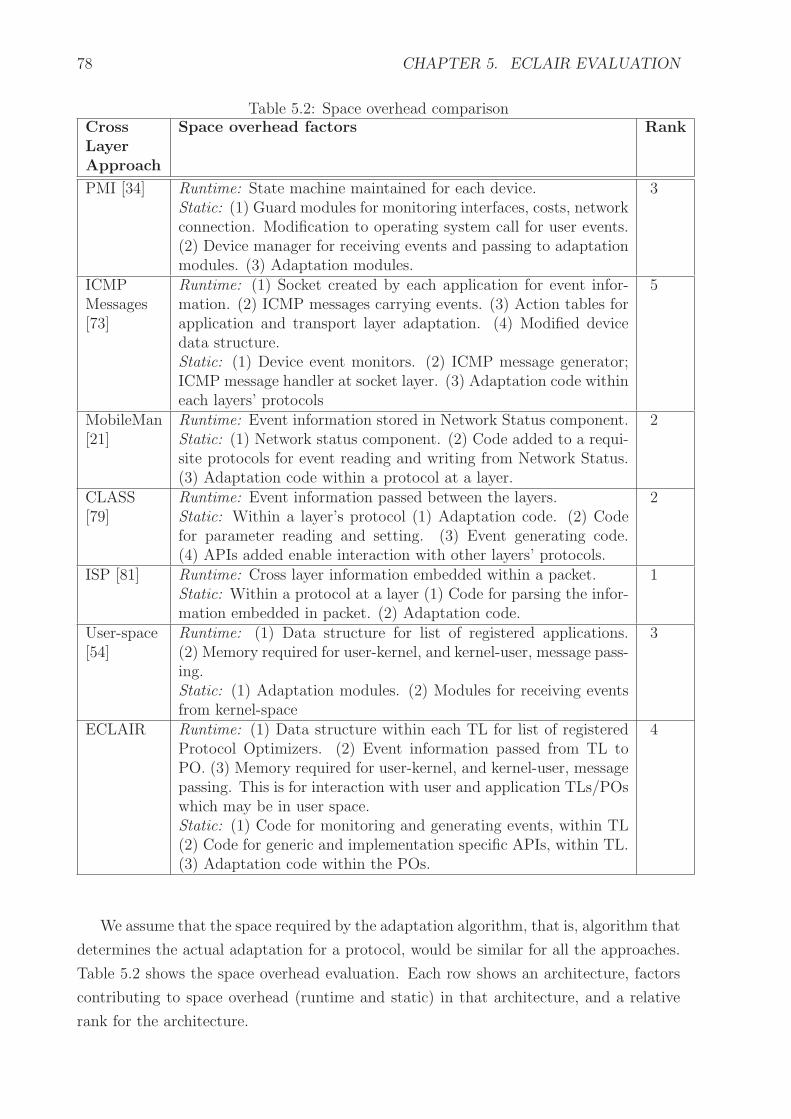
78 CHAPTER 5. ECLAIR EVALUATION
Table 5.2: Space overhead comparisonCrossLayerApproach
Space overhead factors Rank
PMI [34] Runtime: State machine maintained for each device.Static: (1) Guard modules for monitoring interfaces, costs, networkconnection. Modification to operating system call for user events.(2) Device manager for receiving events and passing to adaptationmodules. (3) Adaptation modules.
3
ICMPMessages[73]
Runtime: (1) Socket created by each application for event infor-mation. (2) ICMP messages carrying events. (3) Action tables forapplication and transport layer adaptation. (4) Modified devicedata structure.Static: (1) Device event monitors. (2) ICMP message generator;ICMP message handler at socket layer. (3) Adaptation code withineach layers’ protocols
5
MobileMan[21]
Runtime: Event information stored in Network Status component.Static: (1) Network status component. (2) Code added to a requi-site protocols for event reading and writing from Network Status.(3) Adaptation code within a protocol at a layer.
2
CLASS[79]
Runtime: Event information passed between the layers.Static: Within a layer’s protocol (1) Adaptation code. (2) Codefor parameter reading and setting. (3) Event generating code.(4) APIs added enable interaction with other layers’ protocols.
2
ISP [81] Runtime: Cross layer information embedded within a packet.Static: Within a protocol at a layer (1) Code for parsing the infor-mation embedded in packet. (2) Adaptation code.
1
User-space[54]
Runtime: (1) Data structure for list of registered applications.(2) Memory required for user-kernel, and kernel-user, message pass-ing.Static: (1) Adaptation modules. (2) Modules for receiving eventsfrom kernel-space
3
ECLAIR Runtime: (1) Data structure within each TL for list of registeredProtocol Optimizers. (2) Event information passed from TL toPO. (3) Memory required for user-kernel, and kernel-user, messagepassing. This is for interaction with user and application TLs/POswhich may be in user space.Static: (1) Code for monitoring and generating events, within TL(2) Code for generic and implementation specific APIs, within TL.(3) Adaptation code within the POs.
4
We assume that the space required by the adaptation algorithm, that is, algorithm that
determines the actual adaptation for a protocol, would be similar for all the approaches.
Table 5.2 shows the space overhead evaluation. Each row shows an architecture, factors
contributing to space overhead (runtime and static) in that architecture, and a relative
rank for the architecture.

5.2. QUALITATIVE EVALUATION 79
Key observations:
ISP [81] has the least run-time overhead since all the event information is embedded
within the header. Further, no memory is required for maintaining a list of interested
layers. Also, no separate modules are created for adaptation, the adaptation code is
embedded within the protocol stack.
ECLAIR rank is 4. This because during run-time each TL needs to maintain lists of
POs which are interested in events. Further, the static footprint of ECLAIR is also higher
since it requires creation of multiple TL and PO modules. Also, extra code is required
for generic and implementation specific interfaces.
User-Kernel Crossing Evaluation
We now analyze the user-kernel crossing overhead of a cross layer implementation.
Metric:
Recall from Section 5.1.1, that user-kernel crossing metric is the number of times the
user-kernel boundary is crossed during execution.
Analysis:
Here we estimate the number of user-kernel crossings which would occur, during runtime,
if a particular cross layer approach is used. Table 5.3 shows the user-kernel crossing evalu-
ation. The table shows the factors contributing to user-kernel crossing for an architecture
and the relative rank for an architecture.
Key observations:
ISP [81] ranks the best. It requires no separate user-kernel crossing, since the cross layer
information is embedded within the packet header.
ECLAIR rank is 2. This is because ECLAIR requires some amount of user-kernel
crossing for communicating information from user and applications to kernel and vice-
versa.
Data Path Delay Evaluation
We now analyze the data path delay overhead of a cross layer implementation.
Metric:
As stated in Section 5.1.1, data path delay is measured by the delay introduced in the
data path of the stack due to cross layer feedback.
Analysis:
We assume that the adaptation algorithms are same for all the approaches. We highlight
the processing tasks that would impact the data path. Table 5.4 shows the data path
delay evaluation. The table shows factors contributing to data path delay and relative
ranking of the architectures. For architectures such as MobileMan [21], CLASS [79] and

80 CHAPTER 5. ECLAIR EVALUATION
Table 5.3: User-kernel crossing comparisonCrossLayerApproach
User-Kernel crossing factors Rank
PMI [34] User-kernel crossing depends on placement of device manager. Pro-totype shows device manager implemented in user-space. Factors:(1) Passing device guard information to device manager (kernelto user-space). (2) Checking status of each device at regular in-tervals (user to kernel). (3) Passing adaptation information fromdevice manager to kernel using operating system APIs (user tokernel). (4) Information passing to/from application adaptationmodule (user-kernel and vice versa).If device manager is in kernel, the user-kernel crossing will reduce.However, point number (4) will still be applicable.
3
ICMPMessages[73]
(1) Definition of transport adaptation action, by each application(user to kernel). (2) Delivering events to interested applications(kernel to user).
2
MobileMan[21]
Application’s read or write to Network Status component (user tokernel).
2
CLASS[79]
(1) Each application passing its QoS requirements to lower layers(user to kernel-space). (2) Events and other information from lowerlayers delivered to applications (kernel to user-space).
2
ISP [81] No additional user-kernel crossing since information is embeddedwithin the packet headers.
1
User-space[54]
(1) Adaptation of protocols using operating system APIs (user tokernel). (2) Passing event information to user-space modules (ker-nel to user).
3
ECLAIR (1) Passing information from user or application to kernel space(user to kernel). (2) Passing event information to application orapplication PO in user-space (kernel to user).
2
ISP [81], since the cross layer implementation is entirely within the protocol stack, the
data path delay factors are the same as those for time overhead, stated in Table 5.1.
Key observations:
ECLAIR rank is 1, because ECLAIR components (TLs and POs) are not embedded within
the stack.
ISP [81] is at rank 4. This is because, a layer needs to modify the packet header, for
passing cross layer information. Further, all layers below need to parse this packet and
carry out adaptation if required. All this, decreases the stack execution speed and hence
leads to increased data path delay.
Above we evaluated efficiency of various cross layer feedback approaches. Next, we
evaluate maintainability of the cross layer approaches.

5.2. QUALITATIVE EVALUATION 81
Table 5.4: Data path delay comparisonCrossLayerApproach
Data path delay factors Rank
PMI [34] No data path delay, since all adaptation is from outside the stack. 1ICMPMessages[73]
Adaptation code is introduced within the existing protocol imple-mentation. Additional protocol variables are introduced. (1) Pro-tocol execution slows down since additional variables need to bechecked. (2) Appropriate adaptation needs to be done within theprotocol. (3) Event delivery through special ICMP messages. IPand TCP protocols will have to handle these additional packets,impacting speed of processing application data packets.
2
MobileMan[21]
Same as that for time overhead (Table 5.1). Within each modi-fied protocol: interaction with the Network Status component andprotocol adaptation.
3
CLASS[79]
Same as that for time overhead (Table 5.1). Within each modifiedprotocol, interaction with other protocols, event generation andevent passing and protocol adaptation.
3
ISP [81] Same as that for time overhead (Table 5.1). Within each modi-fied protocol – encoding information in packet, parsing packet andprotocol adaptation.
4
User-space[54]
Depends on implementation of adaptation modules. If event moni-toring, delivery and adaptation is built into the application or somesystem library on data path, then data path delay is high. An ex-ample is, RWC implementation as specified in reference [54].If the adaptation modules are not on the data path then the delaycould be low.
3
ECLAIR No data path delay, since all adaptation is from outside the stack. 1
5.2.2 Maintainability Evaluation
Rapid prototyping and Degree of Intrusion metrics have similar characteristics. Both mea-
sure the number of changes required to the system for implementing cross layer feedback.
In light of this, we combine the analysis of these two metrics.
Rapid Prototyping Evaluation
In Section 5.1.2, we defined rapid prototyping as the ease with which a cross layer opti-
mization can be added, deleted or changed.
Metric:
The number of changes required to the protocol stack and the number of changes required
to a protocol optimization algorithm, is an indicator of the ease of rapid prototyping.

82 CHAPTER 5. ECLAIR EVALUATION
Degree of Intrusion Evaluation
Degree of intrusion can be estimated by the modifications needed to the protocol stack
for introducing a cross layer feedback optimization.
Analysis:
We assume that some cross layer algorithm needs to be implemented or changed. For this
cross layer algorithm, we then estimate the number of changes that would be required
to the protocol stack or the cross layer system. Table 5.5 shows the rapid prototyping
and degree of intrusion evaluation. The table presents the factors which determine rapid
prototyping and degree of intrusion of an architecture.
Key observations:
User-space [54] ranks 1 for both rapid prototyping and degree of intrusion. This is because
all the modules are implemented in user-space and the system calls provided by the
operating system are used for interacting with the protocol stack. Thus, no changes
are required to the protocol stack. Also, due to these reasons changes can be easily
implemented.
ECLAIR rank is 2 for rapid prototyping and 2 for degree of intrusion. This is because,
a large part of ECLAIR needs to be implemented in the kernel. Further, some changes
may be required to the protocol stack for enabling access to some protocol control data
structures. See Chapter 3, Section 3.2 for an overview of accessibility to protocol stack
data structures.
Portability Evaluation
Metric:
As stated in Section 5.1.2, portability is measured by the number of changes required to
a cross layer implementation, for porting it to another operating system.
Analysis:
We estimate the number of changes required to the cross layer modules, to port it to a new
operating system. For architectures in which the cross layer algorithm is implemented
within a layer, the layer would need to be modified. Table 5.6 shows the portability
evaluation.
Key observations:
ECLAIR rank is 1. This is because ECLAIR provides a generic API which is exported by
the TL to the PO. This generic API invokes the implementation specific API. For porting
to a new operating system, only the implementation specific API needs to be added.
Architectures such as MobileMan [21] and CLASS [79], require modifications to the
protocol stack and hence rank lower than ECLAIR.

5.2. QUALITATIVE EVALUATION 83
Table 5.5: Rapid Prototyping capability and Degree of Intrusion comparisonCross
Layer
Ap-
proach
Rapid Prototyping (RP) andDegree of Intrusion (DoI) analysis
RP
Rank
DoI
Rank
PMI[34]
Changes to protocol stack : None. Changes to existing modules:(1) Adaptation Layers to enable new adaptation. (2) Guard mod-ules for adding new events.
2 1
ICMPMes-sages[73]
Changes to protocol stack: (1) Protocol for (a) addition of newparameters, (b) addition of adaptation code.Changes to existing modules: (1) All applications to enable defi-nition of new adaptations for protocols. (2) ICMP message gen-erator to create new events. (3) ICMP message handler, in thesocket layer to update new variables defined for the protocols.
4 3
Mobile-Man[21]
Changes to protocol stack: (1) Protocol for introducing new op-timization or event. For new events: (2) Network Status compo-nent. (3) All the protocols which would use the new event.Changes to existing modules: As above, since all the modules arewithin the protocol stack. Further, changes may be required toapplications to handle the new or modified event.
4 4
CLASS[79]
Changes to protocol stack: (1) Protocol changed to introduce newoptimization or event. (2) If any API of a protocol p is modifiedor a new API or event is introduced, changes are required to allprotocols interacting with p.Changes to existing modules: As above, since all the modules arewithin the protocol stack. Changes may be required to applica-tions to handle the new or changed event.
5 4
ISP [81] Changes to protocol stack: If new adaptation information addedin packet header, modification required to (1) Protocol to embednew information in the packet. (2) All lower layer protocols thatintend to use the new (or changed) information. This is requiredto enable parsing of the packet and subsequent adaptation.Changes to existing modules: As above, since all the modules arewithin the protocol stack.
3 4
User-space[54]
Changes to protocol stack: None. Changes to existing modules:Addition of appropriate modules or modification to existing mod-ules, in user-space.
1 1
ECLAIR Changes to protocol stack: Protocol stack may require modifica-tion if the required data item is not accessible, as discussed inChapter 3, Section 3.2.Changes to existing modules: For new optimization, (1) new Pro-tocol Optimizer is added (PO) or existing PO is modified. Fornew event, changes required to – (2) Tuning Layer (TL) . (3) POswhich would be interested in the new event.
2 2

84 CHAPTER 5. ECLAIR EVALUATION
Table 5.6: Portability comparisonCrossLayerApproach
Portability Analysis Rank
PMI [34] Adaptation layers use the operating system APIs. Similarly, guardmodules directly monitor data structures within the operating sys-tem or use the operating system APIs. For porting to another oper-ating system: (1) Adaptation modules and guard modules will needto be updated to use the new operating system APIs. (2) Guardmodules will require modifications to allow it to directly monitorthe new operating system data structures.
2
ICMPMessages[73]
The protocol implementation is modified by introducing new con-trol variables and the protocol algorithm is modified for adaptation.For porting to another operating system, the new stack will requiremodifications: (1) Protocol modifications will need to re-writtenfrom scratch. (2) Applications may need modifications if the oper-ating system API for the application changes. (3) ICMP messagehandler checks the socket data structure. Thus it would need to bere-written since the socket data structure implementation would bedifferent in the new operating system.
3
MobileMan[21]
The protocols are replaced with new Network Status aware proto-cols. For the new operating system, the protocol implementationswill have to re-written from scratch.
3
CLASS[79]
Protocol implementations are modified to allow interaction withother protocols in other layers. For the new operating system, theprotocol implementations will have to re-written from scratch.
3
ISP [81] Protocol implementations are modified to enable embedding ofcross layer information in packet headers, parsing such informationand adaptations. For the new operating system, implementationswill need to be re-written from scratch.
3
User-space[54]
User-space modules would require modifications to the extent ofchange in the operating system APIs.
2
ECLAIR Tuning Layers (TLs) provide generic and implementation specificAPIs. For the new operating system, additional implementationspecific APIs need to be added to the TL. Thus, only Tuning Layerneeds to be updated to allow interaction with the new operatingsystem.
1
Above we qualitatively evaluated the efficiency and maintainability of ECLAIR as
compared to other cross layer feedback approaches. Next, we present a summary of the
qualitative evaluation.

5.2. QUALITATIVE EVALUATION 85
5.2.3 Qualitative Evaluation Summary
The summary is shown in Table 5.7. The table also includes information whether an
architecture supports any-to-any layer communication.
Key observations:
The results shows that ECLAIR is useful when a balance between efficiency and main-
tainability is required. The qualitative evaluation shows that ECLAIR trades-off efficiency
for enhancing maintainability. Since ECLAIR components are outside the stack, its ef-
ficiency is lower as compared to architectures (example ISP [81]) which implement cross
layer feedback within the protocol stack. However, due to this ECLAIR maintainability
is higher. Table 5.8 presents a summary of the key advantages and limitations of the
various cross layer approaches.
Appropriateness of an architecture would depend on the requirements for cross layer
feedback. In Chapter 7 we present a simple technique for cross layer architecture selection
based on the deployment requirements.
Table 5.7: Comparison of cross layer architectures: Summary
ArchitectureEfficiency Maintainability Any-
Anylayer
Tim
eov
erhea
d
Spac
eov
erhea
d
Use
r-K
ernel
cros
sing
Dat
apat
hdel
ay
Rap
idpro
toty
pin
g
Deg
ree
ofin
trusi
on
Por
tability
PMI [34] 4 3 3 1 2 1 2 NoICMPMessages[73]
5 5 2 2 4 3 3 No
MobileMan[21]
2 2 2 3 4 4 3 Yes
CLASS [79] 2 2 2 3 5 4 3 YesISP [81] 1 1 1 4 3 4 3 NoUser-space[54]
2 3 3 3 1 1 2 No
ECLAIR 3 4 2 1 2 2 1 Yes

86 CHAPTER 5. ECLAIR EVALUATION
Table 5.8: Cross Layer Architectures: Summary observationsCrossLayerApproach
Key Advantages Key Limitations
PMI [34] Adaptation is from outside thestack. Hence it has low data pathdelay and low degree of intrusion.
Event propagates through eachadaptation module at a layer.Hence time overhead is high.
ICMPMessages[73]
The cross layer adaptation modulesare within the kernel. Hence userkernel crossing overhead is low.
Cross layer optimizations are builtinto the protocol stack. This leadsto high time and space overheads.
MobileMan[21]
All the network event information isavailable in a single Network Statuscomponent. Thus time overhead islow.
Existing protocols have to be re-placed to make them Network Sta-tus aware. Thus results in poormaintainability and high data pathdelay.
CLASS[79]
Protocols directly interact withother protocols for cross layer feed-back. Due to this, the time over-head is low.
The protocol stack is modified toenable protocol interactions. Thus,the maintainability is poor and datapath delay is high.
ISP [81] Cross layer information is embed-ded with the packet header. Proto-col adaptation is built into the pro-tocol. Hence, the time overhead islow.
Protocol stack has to be modifiedto introduce adaptations and feed-back. This results in poor main-tainability and high data path de-lay.
User-space[54]
All adaptation modules are imple-mented in user-space. Operatingsystem APIs are used for adapta-tion. Thus, maintainability is high.
Event and adaptation informationhas to repeatedly cross the user-kernel boundary. Hence, the effi-ciency is low.
ECLAIR Adaptation is from outside thestack. Generic and implementationspecific APIs are provided for pro-tocol adaptation. Due to this, theportability is high.
Multiple modules are created formonitoring and adaptation whichinteract through APIs. This resultsin high time overhead.
In the next section, we use Receiver Window Control (RWC) (see Section 4.1) as
an illustrative example, for a quantitative evaluation of the efficiency of ECLAIR. We
compare the ECLAIR and user-space implementations of RWC.
5.3 Quantitative Efficiency Evaluation for RWC
To understand the RWC implementation clearly we first carry out the functional analysis
of the ECLAIR (Chapter 4) and user-space [54] implementations. We use the standard
software engineering design techniques like structure chart and sequence diagram [36] for
our analysis. Besides structure chart and sequence diagrams, for ease of understanding
5.3. QUANTITATIVE EFFICIENCY EVALUATION FOR RWC 87
cross layer feedback implementation aspects, we propose a notation for the protocol stack
and cross layer feedback below.
5.3.1 Cross Layer Feedback Notation
Figure 5.1 depicts our notation for a protocol and a protocol stack. Figure 5.1(a) shows
the notation for a protocol implementation within a layer. Each protocol is made up of
algorithms (for example, congestion control algorithm, etc in TCP), control data structures
(that is, data structures which contain information about the state of the layer), protocol
data unit (PDU) buffers (that is, the data which is worked upon by the layer). Data
path is the sequence of functions within the protocol stack which are concerned only with
sending and/or receiving packets. In Figure 5.1, notation for a protocol is as follows:
• Protocol’s set of algorithms is denoted by a circle.
• Control data structure (cds) is denoted by a rectangle with rounded corners. Control
data structures used by an algorithm are shown attached to the algorithm by a fine
dotted line.
• Protocol data unit buffer (pbuf) is denoted by an open rectangle with sharp corners.
For the stack:
• Stack processing path or data path is shown by a solid line from the algorithms at
a layer to algorithms at an adjacent layer (see figure 5.1(b)). The data path passes
through a protocol data unit buffer.
Figure 5.1(b) shows the protocol stack made up of multiple stacked protocols. User-
space implies the memory which is accessible to user programs and kernel-space is the
memory for the kernel.
Cross Layer Notation Limitations: Our notation for cross layer feedback only provides an
overview of the implementation. The notation does not show the exact data structures of a
protocol. Also, the notation does not depict the mechanism for interaction of components
within the kernel or across user-kernel space.
5.3.2 ECLAIR and User-space: RWC Comparison
Figure 5.2 shows the implementation approach for RWC and ECLAIR. The dotted line
with a hollow arrow head represents a read of values from a data structure or another
module. The solid line with a solid arrow head represents a write or update of values
in a data structure. Read arrows which cross the user-kernel line represent data passing
between user and kernel space.

88 CHAPTER 5. ECLAIR EVALUATION
cds
pbuf
pbuf = Protocol data unit buffercds = Control data structure
Dat
a pa
th
Algorithms
Data path
cds
pbuf
Dat
a pa
th
Protocol
(a) Single protocol implementation
USER spaceKERNEL space
Tra
nspo
rt la
yer
(TC
P)
App
licat
ion
laye
r
Dat
a pa
thD
ata
path
(b) Protocol stack
Figure 5.1: Protocol stack schematic
RWC Implementation Overview
Figure 5.2(a) depicts the implementation overview for the approach proposed in refer-
ence [54]. It can be seen that, the user-space RWC module is on the data path. Further,
user-kernel crossing would be required for updating TCP control data structures.
Figure 5.2(b) shows the ECLAIR implementation. It can be seen that in case of
ECLAIR, the RWC module is not on the data path. Further, user-kernel crossing is
required only when the application information is to be passed to the RWC module.
Functional Analysis
User-space implementation:
Figure 5.3 shows the structure chart for the user-space implementation of RWC. The
arced arrow shows that the RWC module is invoked repeatedly. In the user-space imple-
mentation [54] applications register with the RWC module. This RWC module is invoked
on every read() by the registered applications. To modify the receiver window values,
the operating system function calls getsockopt() and setsockopt() are invoked within
read(). This is implemented by overriding standard C library (libc) functions read()
and connect(), through a new user defined library [54].
ECLAIR:
Figure 5.4 shows the structure chart for the ECLAIR implementation of RWC. The arced
arrow shows that the RWC module is invoked repeatedly. In the ECLAIR implementation,

5.3. QUANTITATIVE EFFICIENCY EVALUATION FOR RWC 89
Ar
A tcp
ArA tcp
TC
PTCP cds
TCP pbuf
Application cds
read priorityinformation
USER spaceKERNEL space
read / update socket thru TCP
− TCP algorithms− RWC Algorithm
App
licat
ion
laye
r
(a) User-space implementation
A tcp
ArA tcp
Ar
USER spaceKERNEL space
− TCP algorithms− RWC Algorithm
read
prio
rity
info
rmat
ion
TCP cds
TC
P p
buf
read / update socket
App
licat
ion
laye
rT
CP
Application cds
(b) ECLAIR implementation
Figure 5.2: Receiver Window Control implementation
the application registers for RWC and passes the required parameters to the RWC module.
This is the only time when user-kernel crossing occurs. RWC is invoked at regular intervals
by a timer within the kernel. The tuning layer has access to the TCP data structures and
updates the receiver window values directly.
Time overhead
From Figure 5.3 it can be deduced that, time overhead for the user-space implementa-
tion [54] is
O(m × n) (5.1)
where n is the number of applications and m is the number of read() calls per application.
Besides the execution time of the RWC module, the time overhead may increase further
due to the operating system calls that are invoked e.g. getsockopt(), tcp getsockopt(),
etc. This increase would depend on the implementation of these system calls in the
operating system.
In case of ECLAIR, the time overhead is
O(t × n) (5.2)
where n is the number of applications and t is the number of times the RWC algorithm
is invoked by the timer.

90 CHAPTER 5. ECLAIR EVALUATION
tcpsetsockopt
RegisterApplication
n applicationsm calls per appO(m*n) crossings
n applications
m calls per app
getsockopt
tcpgetsockopt
setsockopt
UpdateCalculateParameters
CalculateBandwidth
ReceiverWindowControl
application
user spacekernel space
Figure 5.3: Receiver Window Control: Structure chart – user-space
RegisterApplication
ReceiverWindowControl
TCP_TL_get_rtt TCP_TL_set_win
Calculate Update
ReceiverWindow
Control Timer
application
user space
kernel space
n applicationsO(1) crossings n applications
Bandwidth ParametersCalculate
Figure 5.4: Receiver Window Control: Structure chart – ECLAIR
Space overhead
The runtime space overhead of user-space implementation [54] is
O(n) (5.3)
This is the memory required for storing information about the registered applications.
The runtime space overhead for the ECLAIR implementation is the same as that of
user-space, that is
O(n) (5.4)
This is the space required for registering application information.

5.3. QUANTITATIVE EFFICIENCY EVALUATION FOR RWC 91
User Kernel Crossing
In case of user-space implementation [54], since the RWC module is invoked on each read
from user-space, it is evident from Figure 5.3 and 5.2(a) that the user-kernel crossing is
O(m × n) (5.5)
where, n is the number of applications and m is the number of reads per application.
In case of ECLAIR, all the application information can be passed to the RWC module
in a single user-kernel crossing. Thus from Figure 5.4 and Figure 5.2(b) we can deduce
that the user-kernel crossing for ECLAIR is:
O(1) (5.6)
We assume that the number of modules in the structure chart is a measure of the
static memory footprint. Based on this measure, the static memory footprint of ECLAIR
seems to be higher than that for user-space implementation[54]. This is because the TLs
also need to be implemented. Whereas in the case of user-space implementation, existing
operating system function calls are used.
To gain an insight into the data path delay, we present sequence diagrams of the
implementations in the next section.
Data-path Delay
Data send and receive in protocol stack:
To understand the concept of data path delay, we first present the sequence diagram of
send and receive data paths of an unmodified protocol stack in Figure 5.5. The sequence
diagram shows the sequence of function calls between the various entities in the protocol
stack. Figure 5.5 shows how an application sends and receives data, using TCP/IP. For
sending, the application invokes send() on the socket. In turn the send() of TCP then
IP is invoked. Finally, the packet is sent out on the network. While receiving the data, the
application issues a read() call on the socket, which issues a read() on TCP. Whenever
data is received from IP, it is delivered to the application. This is shown as data over the
dotted arrows.
Data send and receive: user-space RWC
In case of user-space implementation [54], RWC is built into the read() of the application.
Figure 5.6(a) shows the modified data path for the user-space implementation. The
data-a return shows the actual return path if read() was not modified. It can be seen
from the figure that the data return from the modified read() is delayed till the RWC
algorithm completes its run. This is the data path delay. Considering all the registered

92 CHAPTER 5. ECLAIR EVALUATION
applications together, excluding other overheads, the overall data path delay (Figure 5.3)
is
O(m × n) (5.7)
Data send and receive: ECLAIR RWC
Figure 5.6(b) shows the data path for the ECLAIR implementation of receiver window
control. The ECLAIR implementation is not on the data path and hence does not impact
the data path of the application.
Other limitations of user-space mechanism
Most operating systems provide APIs for applications, such as getsockopt() and setsockopt(),
to read and update the socket parameters. However, the manipulation of protocol pa-
rameters is restricted to what is permitted by the operating system. For example,
setsockopt(), which internally calls tcp setsockopt(), allows changes to a limited set of
TCP parameters. tcp setsockopt() allows update to window clamp in the TCP control
data structure. However, in case of Receiver Window Control, the value of rcv ssthresh
was also to be updated. This was not possible through setsockopt(). Further, our trails
show that reducing window clamp does not have an effect on an active session. This
has also been stated in reference [78]. Similarly, getsockopt() cannot read the values
of certain TCP parameters individually. For example, for reading the state of a TCP
connection, an info structure (which has many other parameters also) is used.
In summary, some of the operating system APIs, that enable interaction with the
stack, may not provide the flexibility required for implementing a cross layer feedback
system. Moreover, the APIs restrict the usage to user level programs, which would impact
the efficiency of a cross layer implementation. There would be an additional efficiency
penalty due to repeated user-kernel crossing. See Section 5.1.1 for user-kernel crossing
metric.
In this section we compared the user-space and ECLAIR implementations of RWC.
Through analysis we showed that ECLAIR is an efficient architecture for RWC type of
cross layer feedback.
5.3.3 Quantitative Evaluation Summary
Table 5.9 shows the quantitative evaluation summary of ECLAIR and user-space imple-
mentations of receiver window control. (see equations (5.1) - (5.7)). Both have similar
level of maintainability and minimum intrusion. Portability of the ECLAIR implementa-
tion is higher, because of the TLs. In the next section we measure ECLAIR overheads.

5.3. QUANTITATIVE EFFICIENCY EVALUATION FOR RWC 93
synchronous_function()
calli
ng o
bjec
t
asynchronous_function()
return_value_data calle
d ob
ject CLASS:instance
elapsed time in synchronous_function
:application
send()send()send()send(data)
read()
data
read()
data
receive()
:socket TCP: IP:
Figure 5.5: Sequence diagram of data send and receive paths for an unmodified protocolstack
:application
register()
send(data)
read() read()
rwc()
read()
send() send()
receive()
send()
IP:TCP::socket
data pathdelay
data
register()
send(data)
read()
data
send()
receive()
send()
(b)
(a)
:application :socket TCP: IP:
setsockopt() tcpsetsock()
tcpgetsock()getsockopt()
timer()measure()
rwc()data
read()
send()
works in parallelECLAIR: RWC is not on the data path
setvalues()
RWC:
RWC:
data−a data−a
Figure 5.6: Data send and receive with RWC: (a) user-space (b) ECLAIR

94 CHAPTER 5. ECLAIR EVALUATION
Table 5.9: ECLAIR and user-space quantitative comparison summary
Evaluationmetric
ECLAIR user-space Description
Time over-head (com-plexity)
O(t × n) O(n × m) n = number of applicationst = number of invoca-tions of RWC (ECLAIR)m = number of invocations ofRWC per application (user-space)
Space over-head (com-plexity,footprint)
complexity:O(n), foot-print:higherinitially
complexity:O(n), footprint:lower
Space complexity: Spacerequired for informationabout registered applicationsfootprint: static space required forexecutables
User-kernelcrossing
O(1) O(n × m) ECLAIR: time requiredfor passing user parame-ters to kernel using ioctl()
user-space: time requiredfor getsockopt() andtcp getsockopt()
Data path de-lay
- O(n × m) (same as above)
n is the number of applications,
m is the number of reads per application in user-space case,
t is the number of times the RWC algorithm is invoked in ECLAIR
5.4 ECLAIR Overhead Measurement
The broad aim of the profiling experiments is to verify that ECLAIR imposes minimal
overhead on the operating system. Due to non-availability of the implementation code of
existing cross layer approaches (discussed in Section 5.2), profiling of these approaches is
not feasible. Hence we compare ECLAIR with the following:
• Modifying the protocol for cross layer feedback: This would enable comparison of
ECLAIR with all architectures where the cross layer algorithm is built into the data
path.
• Using operating system APIs for cross layer feedback: This would enable compar-
ison of ECLAIR with architectures which are implemented in user-space and use
operating system APIs. Since, ECLAIR is outside the stack, it needs to locate the
data structure that is to be monitored or updated. This adds to the time overhead.
Hence, we also compare ECLAIR efficiency in searching data structures within the
protocol stack, to the operating system API efficiency. We use RWC as the example.

5.4. ECLAIR OVERHEAD MEASUREMENT 95
• No modifications to the stack: This comparison would give us an estimate of ECLAIR
impact on data path delay with reference to the case when no cross layer feedback
is implemented.
In section 5.1.1 we identified time overhead, space overhead, data path delay and user
kernel crossing as the metrics for efficiency. The above stated experiments would give
us an estimate of ECLAIR performance for user-kernel crossing and data path delay
metrics, relative to other approaches. Determining time and space overhead requires
implementation of a full cross layer optimization. Hence, we do not focus on the time and
space overhead. Next, we describe the profiling tools we experimented with.
5.4.1 Profiling Tools
In Chapter 4, Section 4.1 we presented the design and implementation of Receiver Window
Control using ECLAIR. We use that prototype implementation with modifications for
profiling ECLAIR.
To measure the data-path delay overhead, measurement of the impact on the time
taken for packet movement between the network interface and the socket layer is re-
quired. For user-kernel crossing time measurement time-stamps in user and kernel space
are required. For data structure search time, a facility for time-stamp before and after
search is required. This type of profiling requires a lightweight (imposes minimal run-time
overheads on the operating system) profiling tool which can be easily integrated with the
operating system’s protocol stack.
The following open source tools are suitable for the above measurements, in Linux [99]:
• MAGNET (Monitoring Apparatus for Generic kerNel Event Tracing) [28, 103].
MAGNET was earlier known as MAGNeT (Monitor for Application Generated Net-
work Traffic). This tool is available for download from [103].
• LTT (Linux Trace Toolkit) [87]. This tool is available for download from [102].
MAGNET
MAGNET [28, 103] is a tool that traces packets as they move through the protocol
stack. Both packet receipt and packet send are traced. MAGNET requires modification
to the operating system stack. Hooks (function calls) are placed in the protocol stack.
The hooks are placed in link, IP and TCP layers. These hooks call a MAGNET data
recording procedure. This recorded data can be accessed by user-space applications.
Figure 5.7 [28] shows on overview of the operation of MAGNET. The application
issues send() or recv() calls for sending or receiving data. Inside the protocol stack,
TCP, IP and other protocols are used for data send and receive. magnet add() is called

96 CHAPTER 5. ECLAIR EVALUATION
from within the protocol stack to trace packet movement. magnet read() is used to copy
the trace from the kernel buffer to a disk file. MAGNET uses the CPU cycle counter for
generating high-resolution time-stamps.
Figure 5.7: MAGNET details [28]
LTT
Linux Trace Toolkit [87, 102] has the following components: kernel patch which logs events
to be traced, kernel module which stores events and interacts with trace daemon, trace
daemon which reads kernel module’s output and stores it on disk, data decoder which is
used for analysis and converting the trace to human readable form [102]. Figure 5.8 shows
LTT architecture.
Figure 5.8: LTT details [87]

5.4. ECLAIR OVERHEAD MEASUREMENT 97
OProfile
Another tool that we considered was Oprofile [105]. OProfile is a low overhead continuous
profiler. It regularly samples the CPU registers. It converts this sampled information into
a statistical report about which program was executed how often. We experimented with
this tool also (by patching the kernel, recompiling and running a few tests). The tool
could provide information about which code segment occupied the CPU for what fraction
of time. However, there was no facility to measure the time for packet movement within
the stack. Hence, we did not use this tool.
5.4.2 Instrumenting the Linux kernel
Both the profiling tools MAGNET [28, 103] and LTT [87, 102] provide Linux kernel
patches for updating the kernel source code, to enable kernel profiling. Hence we patched
the Linux 2.4.19 kernel with both the tools. We used the 2.4.19 kernel since this was
supported by both the tools. The kernel source code is available at the Linux kernel
source site [101] and the IIT-Bombay mirror site [100]. The patch installation required
some manual editing of kernel source files. This was required since the patches of both
the tools updated some common files at similar locations. Hence, the patch which was
installed second failed at some points.
Only MAGNET used: We intended to use both the profiling tools since we required
features of both the tools. For data-path delay profiling we required the facility to trace
packet movement within the stack. We also wanted to trace the start and end of RWC
invocation.
MAGNET provides the feature of tracing packet movement within the stack and LTT
allows creation of user defined events in kernel modules and user programs. However, LTT
cannot trace a packet’s movement within the stack, although it provides events related
to packets crossing the network and socket layers. This combination would have enabled
us to do the required tracing. However, during our experiments we noticed that the LTT
overheads significantly skewed the readings for data-path delay. We noticed this because
of the occasional but extremely large values of data-path delay. We confirmed this by
measuring data-path delay with and without LTT. We ran our full set of experiments,
discussed in Section 5.4.4. Finally, we decided to use MAGNET only for the purpose of
profiling. Due to this it was not possible to trace RWC start and end. However, this
would not affect the quality of the results, since the primary aim was to study the effect
of ECLAIR on data-path delay.
Instrumenting for user-kernel crossing: MAGNET does not provide a facility for
creating and tracing events within an application. For user-kernel crossing we needed a
time-stamp before invocation of a system call in user-space, and after completion of the

98 CHAPTER 5. ECLAIR EVALUATION
call in kernel-space. For this instrumentation we manually modified the kernel. Initially,
we placed the system call do gettimeofday() in TCP to get and print the time-stamp.
During the initial set of runs we noticed that the time measurement granularity (microsec-
onds) available in kernel 2.4.x was not sufficient since the operations that we intended to
measure (data structure search), were taking less than 1 µsec. Hence, for higher accuracy,
we captured the CPU cycles. We used the function get cycles() available in the kernel
include file asm/timex.h. To get the CPU cycles in user-space, we used get cycles()
in the test-application and compiled it with the kernel include file asm/timex.h. Its
prototype is
#include <linux/timex.h>
cycles_t get_cycles(void);
The Linux get cycles() function is used to get timestamps with very low overhead.
CONFIG X86 TSC has to be defined during kernel compilation time, else get cycles()
returns 0. Internally, get cycles uses the function rdtsc (Read Timestamp Counter) for
reading the timestamp counter (TSC). The time for reading of TSC is extremely small
(ten instruction times) compared to the time interval being measured (thousands). Hence,
we have not done any corrections to the measured time, to account for cycles taken to
read the values from the register.
5.4.3 Design of Experiments
The aim of the experiments was to compare ECLAIR overheads with that of other ap-
proaches. We conducted two sets of experiments to
• measure the impact on data path delay
• measure the data structure search time and user-kernel crossing time
For data path delay measurement, simulation of cross layer overhead was required
during some stack activity. For the stack activity we initiated a download from a website.
Overhead simulation
To simulate cross layer feedback execution we executed an empty loop within the kernel.
To simulate an increased load we increased the number of loop executions. While exe-
cuting the download, we ran the empty loop for 2 × 10⁵, 5 × 10⁵, 10 × 105, 15 × 105 and
20 × 105 cycles.

5.4. ECLAIR OVERHEAD MEASUREMENT 99
ECLAIR overhead simulation
In case of ECLAIR we executed the empty loop within the RWC PO. When the PO
received an input from the user, it executed the empty loop. A kernel timer [13] within
the PO controlled the repetition of the loop at regular intervals. We varied this interval
to simulate the effect of repeated execution of ECLAIR. The PO module was removed
from the kernel on completion of an experiment run. This stopped the loop executions.
Protocol modification simulation
To simulate this we modified the tcp v4 rcv() function in TCP (tcp ipv4.c). We in-
troduced an empty loop in this TCP function. This simulated a load on the data path.
Whenever a packet was received this loop was executed in the tcp v4 rcv() function.
Next, we present the experiment setup and results.
5.4.4 Experiment Setup and Results
We ran the experiments on a desktop with the configuration - Intel Pentium4 CPU,
1.90GHz, 256 MB RAM, 256KB cache.
Custom kernels for experimentation:
We compiled separate kernels patched with MAGNET to measure the impact on data
path delay. In one of the kernels we modified TCP to introduce the empty loop. We refer
to this as the TCP-MAGNET kernel. In the other kernel we did not modify TCP. We
used this kernel for ECLAIR measurements and measurement of packet movement when
no cross layer feedback is implemented. We refer to this kernel as the MAGNET-only
kernel.
Experiment 1: Impact on data path delay
In this experiment we measured the time taken by a packet to traverse up the stack (from
network interface to the socket layer). This is the data path time, when any data is being
downloaded onto the device. We also measured the time taken by the acknowledgments
generated at TCP layer to traverse from TCP to the network interface layer. This is the
data path time for packets being sent out from the device.
We ran wget [107] to download a file from a remote website (www.kernel.org) [101].
A single connection was created. magnet read [28, 103] was started in the background,
to trace packet movement through the stack.
• We ran this experiment on both the TCP-MAGNET and MAGNET-only kernels.
– In the MAGNET-only kernel we ran ECLAIR to simulate cross layer load. We
invoked ECLAIR at different frequencies of 10, 13, 20, 33 and 100 times per

100 CHAPTER 5. ECLAIR EVALUATION
second. 100 per second is the maximum possible invoke frequency using kernel
timers in a 2.4.x kernel.
– In case of TCP-MAGNET kernel, the load was built into TCP layer, as ex-
plained above.
• We also used the MAGNET-only kernel to get a measurement of the packet move-
ment within the stack, when no cross layer feedback is running.
• We repeated each experiment 10 times
– for each load, on the TCP-MAGNET kernel
– for each load and for each invoke frequency – for ECLAIR measurements, in
the MAGNET-only kernel
– without any load to get a measurement for no cross layer feedback, in the
MAGNET-only kernel.
• To check the impact of packet arrival rate also on the data path delay, we selected
two kernel source mirrors for file download, one offering a high throughput and
another lower and repeated the above experiments for each packet rate.
Analysis of Experiment 1
Figure 5.9(a) shows the results for low packet rate. Figure 5.9(b) shows the result for
high packet rate.
Tables 5.10 and 5.11 show the mean and standard deviation values for low and high
packet rate, respectively.
TCP-MAGNET kernel : for this case, since the cross layer load (empty loop) is executed
for every packet, the data path delay is high. Further, the data path delay increases almost
linearly with the increase in cross layer load. Compared to no cross layer feedback, the
data path delay in case of TCP-MAGNET kernel is higher by approximately 49% for low
load (2 × 10⁵) and approximately 30 times higher at high load (10 × 105).
MAGNET-only with ECLAIR kernel : for this case, the load execution is controlled by a
timer. Compared to no cross layer feedback, the data path delay in case of ECLAIR is
higher by approximately 19% in case of low load (2 × 10⁵) and low invocation frequency
(10 times per second). In case of high load (20 × 105) and high invoke frequency (100
times per second), the data path delay is approximately 6 times higher.
Result: This above results show that, ECLAIR’s impact on data path is much lower
than the case of implementing cross layer feedback within the protocol itself.

5.4. ECLAIR OVERHEAD MEASUREMENT 101
0
0.0005
0.001
0.0015
0.002
0.0025
0 5 10 15 20
time
(sec
onds
)
load x 10^5 (empty loops)
Synchronous (in TCP)
ECLAIR freq=100
NoCLF
Synchronous(in TCP)ECLAIR freq=10ECLAIR freq=13ECLAIR freq=20ECLAIR freq=33
ECLAIR freq=100No Cross Layer Feedback
(a) Low packet arrival rate
0
0.0005
0.001
0.0015
0.002
0.0025
0 5 10 15 20
time
(sec
onds
)
load x 105 (empty loops)
Synchronous (in TCP)
ECLAIR freq=100
NoCLF
Synchronous(in TCP)ECLAIR freq=10ECLAIR freq=13ECLAIR freq=20ECLAIR freq=33
ECLAIR freq=100No Cross Layer Feedback
(b) High packet arrival rate
Figure 5.9: Data path delay comparison: ECLAIR v/s TCP modification

102 CHAPTER 5. ECLAIR EVALUATION
Table 5.10: Data path delay: Mean and standard deviation for low packet rate
Invoke Load ×105 X × 10−5 σ × 10−5
frequency(per second) (seconds) (seconds)
No CLF 4.810 ± 1.171 19·84710 2 4.903 ± 1.859 30·417
5 4.411 ± 1.103 18·50710 4.506 ± 0.689 11·67415 12.161 ± 8.625 143·54120 7.884 ± 3.245 49·442
13 2 6.756 ± 3.076 51·1985 3.440 ± 0.175 2·95610 5.249 ± 1.684 28·14715 5.354 ± 0.854 14·32620 6.023 ± 1.634 26·828
20 2 3.489 ± 0.129 2·1465 3.882 ± 0.749 12·54310 6.093 ± 1.849 30·81515 7.038 ± 1.994 33·39420 9.630 ± 3.044 50·453
33 2 3.845 ± 1.067 16·9085 5.878 ± 3.053 47·80610 7.478 ± 2.384 40·34915 11.056 ± 3.320 54·69720 10.585 ± 1.916 31·925
100 2 4.905 ± 2.494 41·8215 6.179 ± 1.541 25·14810 11.309 ± 1.757 29·62915 18.495 ± 2.676 44·47120 28.501 ± 3.417 56·278
Synchronous (in TCP) 0.2 7.164 ± 2.853 48·2962 61.179 ± 39.668 699·9295 74.501 ± 4.334 72·77810 158.373 ± 6.292 105·015

5.4. ECLAIR OVERHEAD MEASUREMENT 103
Table 5.11: Data path delay: Mean and standard deviation for high packet rate
Invoke Load ×105 X × 10−5 σ × 10−5
frequency(per second) (seconds) (seconds)
No CLF 9.549 ± 4.406 152·75910 2 7.486 ± 3.939 118·642
5 11.542 ± 5.181 168·09210 44.305 ± 18.059 579·23515 38.024 ± 19.379 625·80520 28.674 ± 10.518 345·489
13 2 18.468 ± 8.868 285·2955 18.436 ± 8.301 265·43910 16.443 ± 6.980 225·7615 18.798 ± 7.506 242·97720 32.203 ± 15.980 523·711
20 2 12.966 ± 5.132 164·5675 24.851 ± 11.472 367·19910 18.599 ± 10.680 343·18615 17.993 ± 8.038 259·83620 36.171 ± 16.270 537·46
33 2 13.912 ± 6.766 219·9025 17.429 ± 8.934 287·13710 37.503 ± 17.780 571·26915 50.871 ± 21.883 731·21520 24.931 ± 11.905 399·365
100 2 29.779 ± 12.380 336·8425 32.297 ± 13.281 428·94110 23.471 ± 8.824 282·73715 44.926 ± 18.624 601·48320 39.796 ± 9.016 299·111
Synchronous (in TCP) 0.2 15.792 ± 10.137 318·3032 75.832 ± 13.294 501·4235 125.026 ± 9.725 338·05710 217.152 ± 10.074 351·64

104 CHAPTER 5. ECLAIR EVALUATION
Experiment 2: Data structure search time and user-kernel crossing
In this experiment, we measure the time take by the RWC PO to search for TCP sockets.
This includes the time for user kernel crossing. We compare this with the time taken by
an operating system API to locate the data structure. We used setsockopt() system
call to update the TCP data structure.
Operating system API search:
The start of the search time is captured just before the API call. In case of TCP sockets,
the setsockopt() system call flow terminates at the function tcp setsockopt(). We
added code within this function to measure the elapsed CPU cycles when this function is
entered. This is the end time of search.
ECLAIR search:
In case of ECLAIR, we captured the CPU cycles before the user invoked RWC and after
the socket was located by the RWC PO. The RWC PO does not use any system calls for
locating the PO. For efficient search we implemented the tcp hashfn(), from tcp ipv4.c
file, in the RWC PO. This function was used to located the TCP hash bucket in which
the socket is located. Once the hash bucket was located, the exact socket was located by
traversing the socket linked list. Since a linked list traversal was involved, we also studied
the impact of the length of the list, that is, the depth of the hash bucket. As discussed
in Section 5.3, in ECLAIR the user parameters can be passed to the RWC PO in a single
user-kernel crossing. We used an array to pass the socket information to the PO and
measured the impact on socket search.
Creating sockets:
We used a modified version of a socket client from the book – Unix Network Program-
ming [71]. For controlling the depth of the TCP hash bucket, we created an array of port
numbers which would hash into the same bucket. For this, we created a script which first
tested the port numbers which hash into the same bucket. The server side port number
and address were fixed (our department’s web server). The client side address was fixed,
that is, our test machine. The test program used these parameters – server address, server
port and client address. The client port was varied to determine the colliding ports. These
port numbers were captured into a two-dimensional array. Each array row had 8 port
numbers which hashed into the same hash bucket.
For the script that ran the experiment, the first parameter was the number of sockets
required per bucket (1 to 8). The next parameter was a multiplier (1 to 5). Thus, when
sockets per bucket was 1, the total sockets created were 1 to 5. When the sockets per
bucket were 2, the sockets created were 2, 4, 6, 8, 10. Finally, the sockets created were a
multiple of 8, that is, from 8 to 40. Each run was repeated 10 times. The results show
values averaged across the runs.

5.4. ECLAIR OVERHEAD MEASUREMENT 105
Effect of CPU cache:
During the experiments we noted that the CPU cache affected the search time, as the
number of sockets were increased. Thus, to study the impact of caching on search time
we carried out two sets of experiments. One with caching allowed and another with the
cache invalidated. We were unable to disable the cache through the BIOS settings, hence
we invalidated the cache by updating the values in a large int array (size 500,000) , using
a for loop. This loop was called before each run in the application before invoking the
operating system API and inside the ECLAIR PO.
Analysis of Experiment 2
The experiment results are shown in Figures 5.10(a) to 5.10(d). The mean and standard
deviation values are shown in Tables 5.12 to 5.15.
1. Scenario 1 (Figure 5.10(a)): No array used; CPU caching allowed:
• setsockopt: The search time per socket decreases as the hash bucket depth
increases. This decrease can be attributed to the CPU cache.
• ECLAIR: The search time per socket increases as the socket depth increases.
This is because the RWC PO needs to travel the linked list of sockets in the
hash bucket. An increased depth means a longer linked list and hence more
time is needed by ECLAIR. The time taken by ECLAIR is approximately 7
times higher than setsockopt when the bucket depth is 8.
2. Scenario 2 (Figure 5.10(b)): No array used; CPU cache invalidated: The cache was
invalidated by processing a large array as explained above.
• setsockopt: The search time increases as compared as the bucket depth in-
creases.
• ECLAIR: The search time increases as in the earlier case. In this case the time
taken by ECLAIR is approximately 2 times the time taken by setsockopt, for
a bucket depth of 8.
3. Scenario 3 (Figure 5.10(c)): Array used; CPU caching allowed:
• setsockopt: The array cannot be used for setsockopt, since the system call
allows processing of one socket at a time. The result of scenario 1 is repeated
here, that is, search time per socket decreases as hash bucket depth increases
due to CPU cache.
• ECLAIR: The array leads to a substantial reduction in the time taken for
search per socket. This is due to the reduction in the user-kernel crossings.
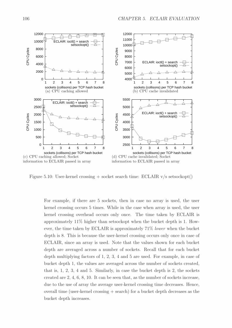
106 CHAPTER 5. ECLAIR EVALUATION
0
2000
4000
6000
8000
10000
12000
1 2 3 4 5 6 7 8
CP
U C
ycle
s
sockets (collisons) per TCP hash bucket
ECLAIR: ioctl() + searchsetsockopt()
(a) CPU caching allowed
4000
5000
6000
7000
8000
9000
10000
11000
12000
1 2 3 4 5 6 7 8
CP
U C
ycle
s
sockets (collisons) per TCP hash bucket
ECLAIR: ioctl() + searchsetsockopt()
(b) CPU cache invalidated
0
500
1000
1500
2000
2500
3000
1 2 3 4 5 6 7 8
CP
U C
ycle
s
sockets (collisons) per TCP hash bucket
ECLAIR: ioctl() + searchsetsockopt()
(c) CPU caching allowed; Socketinformation to ECLAIR passed in array
2500
3000
3500
4000
4500
5000
5500
1 2 3 4 5 6 7 8
CP
U C
ycle
s
sockets (collisons) per TCP hash bucket
ECLAIR: ioctl() + searchsetsockopt()
(d) CPU cache invalidated; Socketinformation to ECLAIR passed in array
Figure 5.10: User-kernel crossing + socket search time: ECLAIR v/s setsockopt()
For example, if there are 5 sockets, then in case no array is used, the user
kernel crossing occurs 5 times. While in the case when array is used, the user
kernel crossing overhead occurs only once. The time taken by ECLAIR is
approximately 11% higher than setsockopt when the bucket depth is 1. How-
ever, the time taken by ECLAIR is approximately 71% lower when the bucket
depth is 8. This is because the user-kernel crossing occurs only once in case of
ECLAIR, since an array is used. Note that the values shown for each bucket
depth are averaged across a number of sockets. Recall that for each bucket
depth multiplying factors of 1, 2, 3, 4 and 5 are used. For example, in case of
bucket depth 1, the values are averaged across the number of sockets created,
that is, 1, 2, 3, 4 and 5. Similarly, in case the bucket depth is 2, the sockets
created are 2, 4, 6, 8, 10. It can be seen that, as the number of sockets increase,
due to the use of array the average user-kernel crossing time decreases. Hence,
overall time (user-kernel crossing + search) for a bucket depth decreases as the
bucket depth increases.

5.4. ECLAIR OVERHEAD MEASUREMENT 107
Table 5.12: Mean and standard deviation: No array used; CPU caching allowed
ECLAIR:ioctl+search setsockopt(CPU cycles) (CPU cycles)
Socketsper bucket X σ X σ
1 10655 ± 82 512 2898 ± 289 18092 10850 ± 62 549 2242 ± 165 14603 11107 ± 58 635 2032 ± 116 12624 11285 ± 113 1422 1918 ± 87 10905 11426 ± 55 776 1834 ± 70 9816 11642 ± 51 780 1789 ± 59 9107 11815 ± 98 1628 1753 ± 50 8398 11823 ± 52 921 1729 ± 44 791
Table 5.13: Mean and standard deviation: No array used; CPU cache invalidated
ECLAIR:ioctl+search setsockopt(CPU cycles) (CPU cycles)
Socketsper bucket X σ X σ
1 10158 ± 86 537 4633 ± 159 9962 10456 ± 65 577 5019 ± 93 8263 10538 ± 58 633 5168 ± 71 7734 10700 ± 53 667 5156 ± 56 7115 10946 ± 124 1734 5225 ± 52 7326 11196 ± 52 799 5268 ± 49 7537 11315 ± 103 1718 5332 ± 93 15428 11525 ± 73 1290 5278 ± 38 680
4. Scenario 4 (figure 5.10(d)): Array used; CPU cache invalidated:
The scenario is similar to the previous one. However, since there is no caching, the
time taken for socket search tends to increase as compared to the case with array
and cache. In this case the time taken by ECLAIR is 14% lower than setsockopt
when the bucket depth is 1 and it is about 37% lower when the bucket depth is 8.
In case of ECLAIR, the time required increases after a depth of 5. This is probably
due to the increase in time required for traveling the socket linked list at higher
bucket depths.
Result: The above experiments show that as the number of sockets increase, by using
appropriate design (array for passing information to PO in kernel), ECLAIR architecture
shows higher savings in case of user kernel crossing. Further, as the hash bucket depth

108 CHAPTER 5. ECLAIR EVALUATION
Table 5.14: Mean and standard deviation: Array used; CPU caching allowed
ECLAIR:ioctl+search setsockopt(CPU cycles) (CPU cycles)
Socketsper bucket X σ X σ
1 2535 ± 549 3434 2274 ± 181 11332 1365 ± 310 2744 2014 ± 121 10693 952 ± 212 2296 1824 ± 81 8774 767 ± 168 2039 1772 ± 66 8015 656 ± 136 1901 1738 ± 52 7366 570 ± 112 1726 1702 ± 44 6777 522 ± 98 1635 1685 ± 39 6588 486 ± 88 1539 1654 ± 33 583
Table 5.15: Mean and standard deviation: Array used; CPU cache invalidated
ECLAIR:ioctl+search setsockopt(CPU cycles) (CPU cycles)
Socketsper bucket X σ X σ
1 3735 ± 424 2654 4345 ± 145 9062 2902 ± 247 2184 4922 ± 90 8013 2713 ± 170 1841 5092 ± 68 7454 2712 ± 130 1630 5135 ± 61 7685 2828 ± 106 1487 5277 ± 186 26086 2980 ± 94 1440 5173 ± 42 6487 3153 ± 85 1408 5213 ± 39 6498 3286 ± 82 1456 5254 ± 41 726
increases beyond 2, ECLAIR shows better performance irrespective of whether caching is
enabled or disabled.
5.4.5 ECLAIR Overheads Summary
The key observations from ECLAIR overhead evaluation are as follows:
• ECLAIR has negligible impact on the data path as compared to implementation of
cross layer feedback within the protocol stack
• By proper design of ECLAIR modules:
– ECLAIR’s user-kernel crossing time is minimized

5.5. ECLAIR LIMITATIONS 109
– ECLAIR’s data structure search time is:
∗ better than an operating system API when the TCP hash-bucket depth is
high
∗ comparable to using an operating system API when the TCP hash-bucket
depth is low
In this section we presented the experiments for measuring ECLAIR overheads. The
analysis in earlier sections and the experiments show that ECLAIR is an efficient and
easily maintainable cross layer architecture. However, ECLAIR has some limitations
which we present in the next section.
5.5 ECLAIR Limitations
The following are some of the limitations of ECLAIR:
• It requires modification to the stack if some data structure is not accessible (see
Chapter 3, Section 3.2).
• A Protocol Optimizer (PO) does not directly access a protocol’s data structure. A
PO uses a Tuning Layer’s (TL) API for this. A PO invokes a TL’s generic API
which in turn invokes the implementation specific API. Thus, execution overheads
are increased due to multiple function calls as compared to direct access to protocol
data structures by the PO.
• ECLAIR modules are not embedded within the existing protocol stack code. Thus,
ECLAIR cannot support per packet adaptation. This is discussed further in Chap-
ter 7. See Chapter 2, Section 2.5.1 for a discussion on adaptation types.
• It does not provide a direct solution to solve cross layer feedback conflicts and
dependency cycles [41].
• It does not provide a direct solution to ensure protocol correctness in presence of
cross layer feedback.
• ECLAIR requires super user privileges for implementation.
However, these are not major limitations. This is due to the following: (1) only minor
modifications are required to the stack to enable access to data structures. (2) The func-
tion call overheads are not significant since, they would form a small fraction of the total
overheads of the cross layer system. (3) ECLAIR does not restrict introduction of addi-
tional mechanisms for per packet adaptation. Thus other architectures can co-exist with

110 CHAPTER 5. ECLAIR EVALUATION
ECLAIR to enable per packet adaptation. (4) Issues such as impact on protocol correct-
ness, cross layer feedback conflict and dependency cycles [41] are intrinsic to cross layer
feedback. These issues would thus exist, irrespective of the architecture used. Although
ECLAIR does not provide a direct solution to these issues, its components (TLs and POs)
can be extended to address these issues. (5) Cross layer system implementers would have
access to the operating system internals and would have super users privileges. Further,
the super user constraint restricts uncontrolled cross layer modifications to the protocol
stack. Next, we discuss some security issues which could be applicable to ECLAIR.
5.6 Security Issues
ECLAIR requires super user privileges for implementation, since ECLAIR components
reside in the kernel. However, introducing these additional components may make the
kernel vulnerable to malicious attacks. Thus, kernel protection is essential. Reference [83]
provides details on how to prevent malicious code attacks launched through loadable
kernel modules. Below we present examples of the security mechanisms which may be
required.
If ECLAIR on the device allows interaction with other components in the network,
it may be possible to send data to the device with the intent of decreasing the device
performance or throughput. Thus, an authentication mechanism may be required between
ECLAIR components within the device and those on the network.
In addition, it may be possible to replace ECLAIR components with malicious compo-
nents, which may impact the device behaviour. Thus a certification or signing mechanism
may be required to ensure that only signed and certified components are installed on the
device. The details about the security mechanisms to ensure device safety is beyond the
scope of this thesis.
5.7 Summary
In this chapter we selected the performance metrics for evaluating any cross layer feedback
architecture. We identified the following metrics: (1) time overhead, space overhead, user
kernel crossing and data-path delay for efficiency (2) rapid prototyping effort (changes re-
quired to the stack and cross layer optimization for adding a new cross layer optimization),
degree of intrusion (changes required to the stack for introducing cross layer feedback) and
portability effort (changes required to the cross layer optimization for porting to another
system) for maintainability.
We compared ECLAIR with other cross layer feedback mechanisms. The comparison
highlights the efficiency and maintainability benefits of ECLAIR. We also compared the

5.7. SUMMARY 111
ECLAIR and user-space implementations of receiver window control. Our evaluation
shows the benefits of using ECLAIR for asynchronous type of protocol optimizations.
Our experimental results verify and the highlight the benefits of ECLAIR.
We present a detailed design guide for ECLAIR in Chapter 7. In the next chapter we
propose improvements to ECLAIR, which would help maximize the benefits of cross layer
feedback using ECLAIR.

112
This page has been intentionally left blank

If you optimize everything, you will always be unhappy
- Donald Knuth
Chapter 6
ECLAIR Optimizations
In the earlier chapters we presented our architecture for cross layer feedback – ECLAIR.
Although ECLAIR imposes low overhead, to maximize the benefit from cross layer feed-
back a well-defined methodology is required for (a) identifying critical cross layer data
items and (b) minimizing overhead for cross layer feedback. A cross layer data item is
information that is available at a layer which can be used for cross layer feedback to other
layers. For example, bit-error-rate information at the physical layer can be considered to
be a data item.
In this chapter we present
• a method for quantifying the utility of a data item and using this to identify the
critical data items and
• a sub-architecture for cross layer feedback which complements ECLAIR.
Our method of identifying critical data items is explained in Section 6.1. It involves
evaluating the utility of a data item. This utility is determined by the efficiency im-
provement of the protocol stack. This efficiency improvement could be in measured by
the decrease in time or space overhead requirement or decrease in the data path delay.
These efficiency metrics have been identified in Chapter 5 for evaluation of cross layer
architectures. Here these metrics are used for measuring the improvement in protocol
stack efficiency. The data items with high utility are considered to be critical.
Our sub-architecture, explained in Section 6.2, proposes partitioning the set of critical
data items into two sub-sets. One of these subsets is called the core. The partitioning is
based on the cost for cross layer feedback of a data item. This cost could be the power
113

114 CHAPTER 6. ECLAIR OPTIMIZATIONS
required for reading a data item from another layer and the power required to make a
data item available to other layers. A data item is placed in core if the cost of cross layer
feedback for the data item is lower when it is placed in the core. Our sub-architecture
would aid in further increasing the benefit achieved through cross layer feedback, by
decreasing the cost of cross layer feedback of the core items.
6.1 Identifying Critical Data Items
To quantify the utility of a data item the exact saving achieved by using the data item
needs to be found. This saving could be determined either by precise models, simulations
or actual measurements. At the design stage, we believe that the estimated frequency of
use of the data item, for cross layer feedback, can serve as an indicator of its utility.
Let, di be a data item at a layer j. i is an index of the set of data items available for
cross layer feedback throughout the stack. For example, some data items are: number of
retransmissions (d1) at the link layer, application priority defined by user (see Receiver
Window Control (d2), Chapter 4) and bit-error rate information at physical layer (d3).
The total number of times, ωi, the data item is accessed by various layers, other than j,
is an indicator of the utility of the data item. Critical data items are the ones for which
ωi is high. The designer may choose to define a threshold or cutoff value for ωi. Now, if
ω3 > ω1 > ω2 then the items ordered by their criticality are d3, d1 and d2.
After the critical data items have been identified the next step is defining the sub-
architecture for cross layer feedback, within ECLAIR.
6.2 Sub-architecture for Cross Layer Feedback
The highlight of our sub-architecture is the creation of a special subset of data items from
the critical data items. We call this subset the core. A data item is placed in the core if
the cost of cross layer feedback for the data item is lower when it is placed in the core.
Figure 6.1 illustrates the concept of core.
6.2.1 Core
Let the critical set of data items available for cross layer feedback be D = {di : ωi > υ},
where υ is a threshold on utility for identifying the critical data items.
Costs related to a data item di:
Let,

6.2. SUB-ARCHITECTURE FOR CROSS LAYER FEEDBACK 115
(e.g.IP)
(e.g.TCP)
(e.g.802.11)
(e.g.802.11)
User
Application
Network
MAC
PHY
ATL
TTL
MTL
PTL
UTL
NTL
Transport
TL = Tuning Layer
Opt
imiz
ing
Sub
syst
em
Cor
e
Figure 6.1: ECLAIR with Core
• the cost of writing the data item into the core:
φ′
i = cw × ω′
i (6.1)
where,
cw = cost of a single write of the value of the data item into the core. Assumed to
be constant for all data items
ω′
i = estimated frequency of writing the value of the data item into the core
• the cost of reading a data item from the core:
φi = cr × ωi (6.2)
where,
cr = cost of a single read of the data item if it is in core. Assumed constant for all
data items
ωi = sum of estimated frequency of access of the data item by all layers, other than
the layer generating the data item value.
• cr = cost of a single read of the data item if it is not in core. Assumed constant for
all data items
Def. 6.2.1 (Core Interaction Cost (CIC)) CIC (Υi) of a data item di is defined as
sum of the cost of writing and reading the data item from the core. From equations (6.1)
and (6.2)
Υi = φ′
i + φi (6.3)
The total cost of core Ψ of core C is the sum CIC of all elements in C
Ψ =∑
Υi for all di ∈ C (6.4)

116 CHAPTER 6. ECLAIR OPTIMIZATIONS
Similarly, the total utility of core Θ is the sum of the utilities of all the data items in
C
Θ =∑
ωi for all di ∈ C (6.5)
Next, it is to be decided whether an item is suitable for the core or not. For this, the
efficiency improvement obtained by putting an item in core needs to be evaluated.
Def. 6.2.2 (Core Potential Score (CPS)) CPS (κi) of a data item di is defined as
the increase in efficiency by placing the item in core.
κi = (cr × ωi) − Υi (6.6)
An item di is suitable for the core C only if κi > 0.
Rearranging the terms of equation (6.6) and from equations (6.1), (6.2), (6.3), we get
κi > 0, if and only if
1 −cr
cr
−cw
cr
×ω′
i
ωi
> 0 (6.7)
Since all the terms in equation (6.7) are positive, it can be seen that:
1. If cr ≥ cr then κi < 0 i.e. the data item is not suitable for core
2. If cr ≪ cr, cw ≪ cr and ω′
i ≪ ωi then κi ≫ 0 i.e. the data item is most suitable for
core
3. If cr ≪ cr, cw ≪ cr and ω′
i ≈ ωi then κi > 0
4. If cr ≪ cr, cw ≈ cr and ω′
i ≪ ωi then κi > 0
In the above two cases also the data item is suitable for the core
5. If cr ≪ cr, cw ≈ cr and ω′
i ≈ ωi then κi ≈ 0 i.e. the data item is not suitable for
core.
6.2.2 Algorithm for Selecting the Elements for Core
Initially C is empty.
Let τ be some threshold for the core. The ordering of the data items ensures that
first the high utility data items are picked for the core. The algorithm is presented in
Figure 6.2.

6.3. EXAMPLE USAGE SCENARIO 117
1.Sort the elements in D based on their CPS’ i.e. the element(s)with the maximum saving is first in the set. Let, D
′ be thesorted set of data items.2.{Check each element}for all di ∈ D
′ do{Check net utility if item in core}if Θ − Ψ < τ then
C = C ∪ {di}else
breakend if
end for
Figure 6.2: Core algorithm
6.3 Example Usage Scenario
In this section we show the use of our sub-architecture, (Section 6.2) through an example.
We use an example, since the exact costs for read and write for data items outside core
or within core cannot be readily determined. Further, the actual data items can be deter-
mined after working with an actual system. In light of this, implementing functionality
of core within the ECLAIR prototype is beyond the the scope of this thesis. We assume
certain cross layer feedback items (see [65] for a survey on cross layer feedback).
Our example assumes the following cr = 1, cr = 0.5, cw = 0.5.
Cross layer data items:
For the sake of simplicity, we consider only four data items:
• d1 = Retransmission information at link layer
• d2 = Losses acceptable to an application (application layer)
• d3 = User defined application priority (see Receiver Window Control in chapter 4,
Section 4.1)
• d4 = Wireless channel bit-error rate
Next, we assume some frequency of write and access for the data items.
• d1: Write frequency ω′
1= 50 per second. The layers that could use this information
are (1) TCP, for adapting its retransmission timeout value and (2) application layer
to get an estimate of the channel condition and adapt its sending rate. We assume
TCP uses this 10 times per sec, while the application uses this information once per
second. Thus, ω1 = 10 + 1 = 11 per second.

118 CHAPTER 6. ECLAIR OPTIMIZATIONS
• d2: Write frequency: ω′
2= 1/600 per second (i.e. application may change its
requirements once in ten minutes). The layers that may read this information
are link layer and IP layer. Link layer could use this information to adapt its error
control mechanisms according to application requirements and channel conditions.
IP layer would read this information to determine the interface on which to send
the packets. We assume that link layer reads this information 50 times per sec and
IP layer reads this information 10 times per second. Thus ω2 = 50 + 10 = 60 per
second.
• d3: Write frequency: ω′
3= 1/600 per second (i.e. user may update application
priority once in ten minutes). This information may be used by RWC (see chapter
4, Section 4.1) to manipulate the receiver window for current applications. We
assume that RWC reads this once every ten minutes. Thus ω3 = 1/600 per second.
• d4: Write frequency: ω′
4= 10 per second (bit-error information from physical layer).
MAC, IP, TCP, and application layers may read this information for adaptation.
We assume each reads this information 10 times per second. Thus ω4 = 40 per
second.
Based on ωi the critical data items can be determined. If the cut-off for ωi was 10,
then d1, d2 and d4 would be the critical data items.
Core:
Using this information and the equations (6.1),(6.2),(6.6) we get:
κ1 = 11 × 1 − (50 × 0.5 + 11 × 0.5) = −19.5
κ2 = 60 × 1 − ( 1
600× 0.5 + 60 × 0.5) ≈ 30
κ4 = 40 × 1 − (10 × 0.5 + 40 × 0.5) = 15
From the values of κi we can see that d1 is not suitable for the core since κ1 < 0.
Using the core algorithm in Figure 6.2, if τ = 35 then d2 will be in the core.
6.4 Summary
In this chapter we presented a method to identify data items which are useful for cross
layer feedback. We also presented our sub-architecture which complements ECLAIR for
an efficient implementation of cross layer feedback. This sub-architecture is general and
not tied to any specific layer to layer interaction.
The sub-architecture uses information like benefit of using a data item for cross layer
feedback, system specific costs for implementing cross layer feedback, and estimated usage
frequency of a data item to suggest an efficient implementation strategy. Through a
example usage scenario we discussed the use of our sub-architecture.
6.4. SUMMARY 119
6.4.1 Limitations of Core Optimization Approach
The sub-architecture proposed in this chapter assumes that costs and frequencies for a
data item i are known. It is assumed that the following are known: cr – cost of single read
of a data item if it is not in core, cr – cost of single read of the data item if it is in core, cw
– cost of single write to the data item into the core, ω′
i – estimated frequency of writing
to the data item in core and ωi – sum of estimated frequency of access of the data item
by all layers. We are not aware of a technique of finding these costs for a device on which
cross layer feedback is to be implemented. Further, we have assumed that the costs are
identical for each data item. This assumption may not hold in a real system. However,
determining the exact costs is beyond the scope of this thesis and does not impact the
sub-architecture design.

120
This page has been intentionally left blank

To err is human, to forgive design
- Andrew Dillon
Chapter 7
Cross Layer Design and Implementation
Guide
In this chapter we present an implementation guide for cross layer optimizations. We
first discuss the types of cross layer feedback. We present a guideline for selecting the
right architecture based on the type of cross layer feedback. We also provide guidelines
for cross layer feedback implementation using ECLAIR.
7.1 Selecting Cross Layer Architecture
To ensure correct and efficient cross layer feedback, architecture selection should be based
on the type of cross layer feedback. Recall from Chapter 2, Section 2.5.1 that the two
different types of protocol adaptations are asynchronous – adaptation occurs in parallel
to protocol execution and synchronous – protocol execution proceeds after adaptation.
Further, the adaptation required could be per flow – separate adaptation for each flow,
across flows – common adaptation for all flows or per packet – protocol adaptation for
each packet.
Per flow and across flows cross layer feedback can be done in asynchronous or syn-
chronous manner depending on the optimization requirements. However, per packet is
essentially synchronous, since adaptation needs to be done as the packet is being pro-
cessed.
121

122 CHAPTER 7. CROSS LAYER DESIGN AND IMPLEMENTATION GUIDE
7.1.1 Architecture Selection Criterion: Feedback Type
We believe that the primary criterion for selecting a cross layer feedback architecture is
the sync-type (asynchronous or synchronous) of adaptation. Incorrect selection would
lead to an impact on the correctness and efficiency.
Impact on correctness
The cross layer feedback behavior would be incorrect, if an architecture suitable for asyn-
chronous adaptation is used for synchronous adaptation. For example, cross layer feedback
adaptation which is to be triggered by information contained in each packet would fail if
an asynchronous architecture like ECLAIR is used.
For per packet (synchronous) cross layer feedback, ISP [81] or CLASS [79] are better
candidates (see Chapter 4 for comparison of the various architectures), since both these
architectures enable direct interaction between layers and the cross layer algorithm is
executed every time the layer code is executed. This is shown in Figure 7.1(a). However,
cds
p
cds
pcd
sq
qpb
uf
Aclf
Aq
Ap
Pro
toco
l p
pbuf
p
Pro
toco
l q
data path
(a) per packet using synchronousarchitecture (ISP)
cds
p
cds
pcd
sq
qpb
uf
Ap
Aq
ECLAIRmodule
Pro
toco
l p
pbuf
p
Pro
toco
l q
A clf
data path
modified data path
(b) per packet using asynchronous architec-ture (ECLAIR)
Figure 7.1: Cross layer feedback per packet1
in case of ECLAIR, the cross layer algorithm is outside the protocol stack and hence cannot
be invoked synchronously for each packet. To use ECLAIR for per packet adaptation, the
data path would have to be modified. This is shown in Figure 7.1(b). The figure notation
was described earlier in Chapter 5, Section 5.3.1. Recall that, for a protocol, its set of
1Refer to Chapter 5, Figure 5.1 for figure notation details

7.1. SELECTING CROSS LAYER ARCHITECTURE 123
algorithms (A) is denoted by a circle, control data structure (cds) is denoted by a rectangle
with rounded corners, protocol data structure (pds) is denoted by an open rectangle with
sharp corners, and for the stack the data path is denoted by a solid line between algorithms
at adjacent layers. Aclf denotes the cross layer optimization algorithms.
Impact on efficiency
As an example, we consider Receiver Window Control (RWC) explained earlier (Sec-
tion 4.1). In this case, the primary requirement is to apportion application bandwidth
such that the bandwidth of each application is in proportion to the user defined priority. It
is not essential to tune application bandwidth synchronously. For example, reference [54]
proposes tuning application bandwidth with each read() of an application. Figure 7.2(a)
shows the implementation of per and across flows cross layer feedback using a synchronous
architecture. Figure 5.2(a) (Chapter 5) shows the implementation specific to RWC (see
Chapter 5, Section 5.3.1 for the cross layer notation). Thus, a synchronous architecture
such as user-space [54] or ISP [81] would lead to reduction in application throughput (see
Chapter 5, Section 5.2 for a comparison of various architectures). However, if an asyn-
chronous architecture, such as ECLAIR is used (Figure 5.2(b)), then the data path delay
and hence application throughput is not reduced. Figures 7.2(b)– 7.2(c) show per and
across flows cross layer feedback using ECLAIR. As can be seen above, the cross layer
feedback implementation would be inefficient if the architecture is not selected as per the
sync-type.
Above, we discussed the impact of architecture selection on correctness and efficiency
of cross layer feedback. Next, we discuss architecture selection based on cross layer im-
plementation requirements.
7.1.2 Architecture Selection Criterion: Implementation Require-
ments
Another important criterion for architecture selection is the implementation requirements.
The cross layer architecture evaluation metrics (Chapter 5, Section 5.1), that is, efficiency
and maintainability metrics are useful for this.
Metric Weightage: Since there are multiple metrics, weights could be used to help
prioritize the metrics. These weights are multiplied with the ranks shown in Table 5.7
(Chapter 5). The sum of the weighted ranks is used to select the appropriate architecture.
Example: We compare the architectures PMI [34], MobileMan [21] and ECLAIR, in
tables 7.1 and 7.2. In the first example, the weights are assigned assuming that efficiency
is more important that maintainability. The weighted rank of PMI is 79, for MobileMan it
is 72 and that of ECLAIR is 74. For the given weights, MobileMan is a better option. This

124 CHAPTER 7. CROSS LAYER DESIGN AND IMPLEMENTATION GUIDE
qpb
uf
cds
q
cds
qcd
spcd
sp
ppb
uf
Aq
Ap
Aclf
Legend:
ReadUpdate
cds = Control data structurepbuf = Protocol data unit bufferA = Algorithms
Pro
toco
l pP
roto
col q
(a) per flow / across flows using synchronous architecture
Ap
Aq
cds
q
cds
q
cds
p
cds
p
qpb
ufp
pbuf
Aclf
ECLAIRmodule
Pro
toco
l pP
roto
col q
(b) per flow using ECLAIR
Ap
Aq
cds
q
cds
q
qpb
uf
cds
p
cds
p
AclfPro
toco
l pP
roto
col q
pbuf
p
CLF
writ
e
CLF
rea
dECLAIRmodule
(c) across flows using ECLAIR
Figure 7.2: Cross layer feedback per flow/across flows2
2Refer to Chapter 5, Figure 5.1 for figure notation details

7.1. SELECTING CROSS LAYER ARCHITECTURE 125
is shown in Table 7.1. However, as shown in Table 7.2, if the weightage of maintainability
is also increased (weight of portability and degree of intrusion is increased to 3 each),
then the weighted rank of PMI is 82, for MobileMan it is 79, while that of ECLAIR is 77.
With the new weights, ECLAIR is a better option.
Table 7.1: Architecture Selection: Weighted Rank - Example 1
Metriccategory
Metric Weig
hta
ge
PM
I[3
4]
PM
IW
eigh
ted
Mob
ileM
an[2
1]
Mob
ileM
anW
eigh
ted
EC
LA
IR
EC
LA
IRW
eigh
ted
Time overhead 8 4 32 2 16 3 24Efficiency Space overhead 7 3 21 2 14 4 28
User-kernel crossing 4 3 12 2 8 2 8Data path delay 4 1 4 3 12 1 4Rapid prototyping 2 2 4 4 8 2 4
Maintain- Degree of intrusion 2 1 2 4 8 2 4ability Portability 2 2 4 3 6 1 2
Weighted Rank – – 79 – 72 – 74
Table 7.2: Architecture Selection: Weighted Rank - Example 2
Metriccategory
Metric Weig
hta
ge
PM
I[3
4]
PM
IW
eigh
ted
Mob
ileM
an[2
1]
Mob
ileM
anW
eigh
ted
EC
LA
IR
EC
LA
IRW
eigh
ted
Time overhead 8 4 32 2 16 3 24Efficiency Space overhead 7 3 21 2 14 4 28
User-kernel crossing 4 3 12 2 8 2 8Data path delay 4 1 4 3 12 1 4Rapid prototyping 2 2 4 4 8 2 4
Maintain- Degree of intrusion 3 1 3 4 12 2 6ability Portability 3 2 6 3 9 1 3
Weighted Rank – – 82 – 79 – 77
ECLAIR suitability for Cross Layer Feedback
The above analysis shows that the appropriateness of an architecture is dependent on the
priority of the design goals, which can be translated to the metric weights. ECLAIR is
suitable when a balance of efficiency and maintainability is required.

126 CHAPTER 7. CROSS LAYER DESIGN AND IMPLEMENTATION GUIDE
In the following sections we present an implementation guide for ECLAIR. Since
ECLAIR is suitable for asynchronous type of adaptation, we restrict the discussion to
asynchronous adaptation.
7.2 ECLAIR Design Guide
In this section we present some design guidelines for cross layer implementation using
ECLAIR. Cross layer feedback implementations may have single or multiple optimizations.
Accordingly, appropriate trade-offs are required between the design goals.
7.2.1 Single Cross Layer Optimization
In ECLAIR, separating the Protocol Optimizers and Tuning Layers into a separate cross
layer system, outside the stack, introduces the overhead of additional function calls.
Hence, in case only a single cross layer optimization is planned and the cross layer system
is not to be ported / deployed on multiple operating systems then it is better to combine
and incorporate the protocol optimizer (PO) and tuning layers (TLs) within the existing
stack itself. This would reduce the overhead of multiple calls between PO and TL and
hence would increase the efficiency of the implementation. However, this would negatively
impact the other cross layer architecture design goals, that is, rapid prototyping, portabil-
ity and minimum intrusion. Hence, if additional cross layer feedback optimizations are to
be introduced later, OSS/PO and TL should be implemented as separate modules. This
is to avoid the maintainability and portability issues later.
7.2.2 Multiple Cross Layer Optimizations
In case of multiple asynchronous type of cross layer optimizations, POs and TLs should
be implemented as indicated in the ECLAIR architecture. This would help achieve the
design goals (Chapter 2). The use of TLs and OSS/POs helps ensure rapid prototyping,
minimum intrusion, portability, efficiency and any to any layer communication.
If multiple cross layer optimizations or POs directly access the layers, then the depen-
dency of the POs is high on the layer’s code. Any change to the layer code will lead to
a change in all the POs interacting with that layer. Reducing such dependency is useful
for ease of maintenance and evolution of the cross layer system. Introduction of a tuning
layer, leads to reduction in the coupling between the layer code and POs. Further, core
should be introduced for reducing the cross layer overheads.
ECLAIR also enables cross layer optimization deployments on mobile devices which
have a separate modem. For example, for a laptop which uses a modem for wireless access,

7.2. ECLAIR DESIGN GUIDE 127
the TLs of MAC and physical layers can be deployed on the modem. These TLs interact
with the OSS/POs on the laptop.
7.2.3 Enabling per Flow Adaptation in ECLAIR
In ECLAIR, their is no specific mechanism to enable per flow cross layer feedback. For per
flow cross layer feedback, the ECLAIR TL needs to locate the flow that is to be monitored
and adapted. For example, in case of TCP at transport layer, the socket identifier (sender
port, address and destination port, address) can be used.
7.2.4 Handling Dependency Cycles and Conflicts
A TL does not have any specific components for handling certain issues which are intrinsic
to cross layer feedback. For example, dependency cycles and feedback conflict [41] are not
handled by any specific component within ECLAIR. Defining such a component is beyond
the scope of ECLAIR. However, ECLAIR components can be used or extended to handle
such cross layer feedback problems.
Dependency cycles: Cross layer feedback can lead to adaptation loops involving mul-
tiple protocols [41]. Kawadia and Kumar [41] propose creation of dependency graphs for
the entire stack. This dependency graph can be used to handle the cross layer feedback
cycles. In ECLAIR, a PO registers with multiple TLs. A new PO can be created that
registers with all the TLs. This PO can collect information from all TLs and create a de-
pendency graph. If cycles are detected, then appropriate TL’s behavior could be changed
using this PO. Details about the exact action on detecting dependency cycles is beyond
the scope of this thesis.
Cross layer feedback conflict: Cross layer conflict [41] occurs when two or more POs
try to update the same data item. A TL can ensure that updates to a data item are
spaced out by some time interval.
7.2.5 Filtering Events at TL
A TL monitors the control data structures of a protocol for changes. A change in the
value of a data structure is an event which is delivered to a PO. However, raw information
about the value of the data structure may not be useful for a PO. Thus, a mapping must
be defined for the information about events.This reduces the granularity of event data.
For example, the bit error rate information may be mapped to some pre-defined levels. A
level would contain a range of values. An event occurs when the bit-error rate changes to
a different level. This level is sent to the PO within the event notification.

128 CHAPTER 7. CROSS LAYER DESIGN AND IMPLEMENTATION GUIDE
7.2.6 Event Queues for POs
Events which are delivered asynchronously to the PO should be stored in priority queues,
by the POs. This would enable a PO to address high priority events first. For example,
disconnection event may be of higher priority than other events. This event priority could
be defined at a system level.
Before processing an event, a PO may scan the queue to determine protocol adaptation
based on the one or more events in the queue. The events which have been processed are
removed from the queue. This could result in reduced execution overheads in case multiple
events occur in a short time. However, queue scanning would increase the execution
overhead.
In this section we presented some design guidelines for ECLAIR. In the next section
we present some implementation guidelines for ECLAIR.
7.3 ECLAIR Implementation Guide
Kernel module background: A kernel module is a binary which can be used to extend
kernel functionality. The module can be compiled separately and loaded into or unloaded
from the kernel at run-time without the need for rebooting the system. A loaded kernel
module can access the kernel data structures like any other part of the kernel.
7.3.1 Tuning Layer Implementation
A TL can be developed as a separate kernel module or built into the kernel. In either
of the cases, TL functions which need to be accessed by POs should be exported (see
Chapter 3, Section 3.2).
TL as loadable kernel module: This is possible if the required control data structures
of the protocol are accessible (see Chapter 3, Section 3.2) without any modification to the
existing protocol implementation code. Then the protocol data structures can be read or
updated by the TL after loading.
TL built into the kernel: In case the TL is built into the kernel, control data structures
of a protocol can be made accessible by following appropriate rules of the C programming
language [42]. In this case, the TL should be compiled with appropriate modules in the
kernel. For example, TCP TL should be compiled with the network modules. This is to
ensure that the TL has access to the protocol data structures.

7.3. ECLAIR IMPLEMENTATION GUIDE 129
7.3.2 Protocol Optimizer Implementation
Similar to a TL, a PO also can be built into the kernel or developed as a separate
module. TLs and POs in user-space are application programs. Each PO and TL can be
implemented as a separate module. This provides the flexibility of loading and unloading
individual modules as required. However, this increases the function call overheads, if
a module calls a function in another module. To reduce the function call overheads, an
alternative is to combine related modules into a single module.
7.3.3 Event Notification within the Kernel
For event notification from TL to PO one of the following mechanisms could be used.
These mechanisms are for intra-kernel communication.
Synchronous event delivery – Notifier chains:
Notifier chain is a linux kernel mechanism for event communication to interested kernel
components. The chain is a linked list of notifier blocks. A interested component registers
its call back function, through a notifier block, with the component(notifier) that imple-
ments the notifier chain. When an event occurs, the notifier traverses the notifier chain
and invokes the callback function in each notifier block, thus passing the event notification
to interested components.
Asynchronous event delivery – Shared data structures:
A set of data structures can be created which is shared between the TLs and POs. One
example is a queue. As compared to notifier chains, the PO may need to poll the data
structure. Further, race conditions and reader/writer problems would need to be handled
for message queues. Also, a mechanism will be needed for deleting events which have
been processed by all the POs. In case of notifier chains, the order of execution of POs
is determined by the order within the notifier chain. In case of common data structures,
the order is determined by the order in which the POs access the common data structure.
7.3.4 Interaction Across User-Kernel Space
System calls:
System calls are the APIs provided by an operating system to applications in user-space,
for example getsockopt() and setsockopt(). However, the existing system calls enable
interaction only with certain components of the operating system. They cannot be used
for interaction with new components added, for example a loadable kernel module. In-
teraction with new components is possible by modifying the implementation of existing
system calls or introducing new system calls.
Character device drivers with ioctl:
ioctl() is also a system call provided by the operating system. The purpose of ioctl is

130 CHAPTER 7. CROSS LAYER DESIGN AND IMPLEMENTATION GUIDE
to enable manipulation of the parameters of special files such as device drivers [23]. This
system call can also be used for interaction with kernel modules. In this case, the kernel
module needs to be implemented as a character device driver. Applications in user-space
can interact with such a module using ioctl.
Event notification to applications:
/proc in Linux:
The proc file system is special file system in Linux. It allows creation of virtual files,
for example, /proc/tcp. Applications can read event information from this /proc file.
However, the information is available only as a string. Further, special functions need to
be defined to be defined by a TL to allow an application to read from the /proc file. Also,
the event information has to be polled by the application.
netlink sockets:
An overview of netlink and its benefits is provided in references [95, 98]. Netlink socket is a
mechanism which enables two-way asynchronous communication between user and kernel-
space. In contrast, ioctl and system calls enable one way (user to kernel) synchronous
communication between user and kernel space. In ioctl and system calls, kernel to user-
space is possible only when the application invokes the call and the kernel returns data
in a variable. Through netlink sockets, however, a kernel component can initiate event
delivery to an application, without an application invocation first. As compared to system
calls, adding a new protocol type or a new constant for netlink sockets is relatively simple.
Another advantage of netlink sockets is that it supports multicast [98]. This is useful when
the kernel needs to send an event notification to multiple applications. Some performance
results for netlink sockets and a benchmark tool is available at reference [4].
7.4 Summary
ECLAIR should be used if the cross layer sync-type is asynchronous. Further, POs and
TLs should be implemented, as proposed in ECLAIR, if multiple cross layer optimizations
are to be implemented or if the cross layer system is to be ported to multiple operating
systems. Core should be introduced to reduce the cross layer overheads.
The TL or PO can be implemented as separate modules or as a part of the kernel.
Kernel modules have the flexibility of being loaded/unloaded during runtime, without the
need for rebooting the system.
Event notification from TL to PO can be done synchronously using callback functions
or asynchronously using a queue data structure. Netlink sockets provide a mechanism
for two-way asynchronous communication between user and kernel space. Netlink sockets
also support event information multicast from kernel to user-space.

Nature’s music is never over; her silences are pauses, not conclusions
- Mary Webb
Chapter 8
Summary and Conclusions
In this thesis, we addressed the need for a systematic approach to cross layer feedback.
Cross layer feedback is essential for improving the performance of layered protocol stacks
deployed over mobile wireless networks. For example, network layer feedback about dis-
connections can be used to adapt and improve the performance of TCP congestion control
algorithm. Cross layer feedback can be implemented on the mobile host or an interme-
diate host, such as the base station. The focus of this thesis is on cross layer feedback
within the mobile host.
We surveyed various proposals for cross layer feedback and highlighted the benefit
of cross layer feedback. We also analyzed various cross layer feedback implementation
approaches – such as PMI [34], ICMP Messages [73], MobileMan [21], CLASS [79], ISP [81]
and user-space implementation [54]. We defined design goals for a cross layer feedback
architecture, based on our analysis of existing approaches to cross layer feedback. We
defined an architecture ECLAIR which satisfies these design goals. Through analysis
and measurements we showed that ECLAIR is a low overhead architecture and aids
maintainability. Below we list the contributions of this thesis.
8.1 Thesis Contributions
• We defined the design goals for a cross layer feedback architecture. The design
goals are: efficiency, rapid prototyping, minimum intrusion, portability and any-to-
any layer communication.
131

132 CHAPTER 8. SUMMARY AND CONCLUSIONS
• We defined a cross layer architecture ECLAIR, which addresses the above design
goals. ECLAIR provides a Tuning Layer for accessing the control data structures
of each protocol. Protocol Optimizers contain the cross layer feedback algorithms.
They use the APIs of a TL to monitor and adapt a protocol.
We observed that adaptation of a protocol on receipt of cross layer feedback can be
asynchronous or synchronous. ECLAIR supports asynchronous adaptations since
its modules are not embedded within the protocol stack.
• We implemented a prototype of Receiver Window Control (RWC) [54, 66] on a
Linux 2.4.19 kernel, to validate ECLAIR. We validated the ECLAIR implementation
through experiments over Ethernet and 802.11 wireless LAN. We compared the
results with RWC simulations in ns-2 [57].
• We defined metrics to evaluate cross layer architectures against the design goals. We
used these metrics to qualitatively and quantitatively compare ECLAIR with exist-
ing approaches to cross layer feedback implementation. We also defined a notation
to enable easy understanding of cross layer feedback implementations.
Our analysis shows that ECLAIR is useful when a balance of efficiency and main-
tainability is required.
• We measured the overheads of ECLAIR, using the RWC prototype implementation
and profiling tools such as MAGNET [28, 103]. Our results show that ECLAIR’s
impact on data path is negligible as compared to architectures which require mod-
ification to the protocol stack. Further, by proper design ECLAIR’s user-kernel
crossing and data structure search time can be lower than that for user-space im-
plementations which use operating system APIs.
• We proposed a sub-architecture core which can be used to select cross layer data
items offering high benefit. Core helps to further reduce ECLAIR overheads.
• We also presented a cross layer design guide. We showed that an architecture’s suit-
ability is dependent on the cross layer deployment requirements. Incorrect selection
can impact the correctness and efficiency. For example, if ECLAIR is used for a
case where synchronous adaptation is required, then the cross layer behavior would
be incorrect. Further, the stack efficiency will decrease if a synchronous architec-
ture is used where an asynchronous adaptation is required. We presented a simple
technique for selecting the appropriate cross layer architecture in line with the im-
plementation requirements. We also presented some design and implementation tips
for cross layer feedback implementation on a Linux system.

8.2. ECLAIR APPLICATION 133
8.2 ECLAIR Application
Mobile device manufacturers regularly improve their devices for enhancing user experi-
ence. Enhancements to the mobile device’s protocol stack is also one of the improvements.
The protocol stack improvement is aimed at enhanced user experience while on data net-
works. Besides other optimizations, enabling cross layer feedback within the protocol
stack would improve the user experience. For example, as discussed in earlier chapters,
battery life could be improved, or download speeds could be improved.
ECLAIR can be used by manufacturers of mobile devices such as mobile phones,
PDAs, laptops, etc. to enable cross layer feedback within the device protocol stack.
ECLAIR would enable cross layer feedback implementation with minimal modifications to
the existing stack. Also, ECLAIR can be used by mobile device manufacturers for rapid
prototyping of cross layer feedback protocol optimizations. ECLAIR implementation
could be done in hardware or software, as per the requirements of the device manufacturer.
The ECLAIR prototype has been developed on Linux, using certain features of Linux,
such as kernel modules. Further, the ECLAIR prototype was developed primarily for the
purpose of ECLAIR validation and performance measurement. Hence, the prototype does
not check for all the constraints or restrictions imposed by Linux. For other operating
systems, some other constraints, restrictions and checks may apply. In addition, the pro-
totype does not fully check or protect against cross layer feedback conflicts or dependency
cycles. Thus, ECLAIR may require further detailing before being deployed on commercial
systems.
8.3 Future Work
In this section, we present an overview of avenues for further research and how work done
in this thesis could be extended.
Improve synchronous cross layer feedback efficiency
We observed that cross layer feedback can be asynchronous or synchronous. We discussed
the types of adaptations in Chapter 2. An example of synchronous feedback is adaptation
by a protocol for each packet. This type of adaptation decreases the protocol stack execu-
tion speed. ECLAIR does not support synchronous adaptation. However, ECLAIR could
be used for synchronous adaptation provided it can be synchronized with the protocol
stack execution. Another option is modifying the data path of the protocol stack to make
it pass through ECLAIR. For example, TCP’s tcp send function could be replaced by a
new function within ECLAIR PO, which incorporates per packet cross layer adaptation.
However, this will require modifications to the protocol stack. In addition, this would lead

134 CHAPTER 8. SUMMARY AND CONCLUSIONS
to increased data path delay, since per packet adaptation is introduced within the data
path. Addition of this component with minimal modifications to the protocol stack, and
ensuring that it imposes minimal execution overheads, are an open research questions.
Further, besides ECLAIR, the other architectures which support synchronous adap-
tation introduce data path delay and hence impact the stack efficiency. It would be in-
teresting to further analyze this and determine optimizations that can be used to reduce
the data path delay.
Enhancement of ECLAIR sub-architecture
Any implementation of cross layer feedback will impose some overheads on the system.
To minimize these overheads, we have proposed a preliminary method for selection of high
utility cross layer data items. These data items are placed together in a sub-system called
core, to minimize the cross layer feedback overheads of these data items. For this thesis,
we assumed that the collective frequency of access of a data item, by the various layers,
is a measure of its utility. Further, we assumed that the read (or write) costs for all data
items are similar. For implementation on actual devices, it is essential to develop proper
models for determining the utility of a cross layer data item. Further, the exact read and
write costs need to be determined for the device on which cross layer feedback is to be
implemented. This will help in identifying appropriate cross layer feedback data items,
and minimizing the cross layer feedback costs.
ECLAIR for base station and other network nodes
We proposed ECLAIR – an architecture for mobile device protocol stacks. The design
goals defined were also for a cross layer architecture on a mobile device. However, ECLAIR
could be extended for use on base station, routers and other network nodes. This would
require addition or changes to the design goals and accordingly extensions to ECLAIR.
As discussed earlier in Chapter 1, cross layer adaptations at a base station would need
to be suited to each device connected to the base station. Thus, some of the important
requirements would be: support for a large number of connections, facility to identify
connections from the same device and support for efficient interaction with the mobile
device – to enable information exchange with it. For addressing these requirements,
ECLAIR would need to be suitably extended. For example, for supporting large number
of connections, the architecture would require a facility for creation of additional Tuning
Layers and Protocol Optimizers as the connections grow. Also, an additional device
component would be needed for information exchange with each devices. Lastly, Protocol
Optimizers would need to interface with this device component to determine adaptations
specific for each device.

8.3. FUTURE WORK 135
ECLAIR for Seamless mobility
Seamless mobility requires feedback between protocols at the same layer. For example,
when moving from a wireless local area network to a wireless wide area network, feedback
would be required between 802.11 MAC and GPRS MAC. ECLAIR provides Tuning
Layers (TL) for each protocol. In Chapter 3, Section 3.4, we presented an example of
seamless mobility using ECLAIR. However, some extensions would be required to enable
ECLAIR to provide information to the network entities, to support seamless mobility.
ECLAIR provides a user TL which can be used for interaction with external entities.
An additional network node component may be needed that interacts with the network
nodes. This component would send device status and other information to the network
nodes and receive information from them. The seamless mobility PO can now use this
network information for adapting the device protocol stack. Details of the network node
component, issues related to efficient information exchange with the network entities and
issues related to simultaneous tuning of multiple protocols on the device, are open research
questions.
Extending ECLAIR to resolve cross layer conflict and dependency cycles
ECLAIR is an architecture for implementing cross layer feedback. There are certain issues,
such as cross layer feedback conflict and dependency cycles [41], which are intrinsic to
cross layer feedback.
Cross layer feedback involves modifying the behavior of the existing protocols, for
example, modifying TCP’s retransmit timer to change its retransmit behavior. However,
there could be a conflict as multiple POs, besides TCP itself, may want to change the
value of TCP’s retransmit timer. It is important to determine which one of the writes
to a protocol’s control data structure is correct at a point in time. Further, cross layer
feedback can lead to adaptation loops involving multiple protocols [41]. A mechanism is
required to trap and resolve such cross layer feedback conflicts and cycles.
ECLAIR does not provide a direct solution to these cross layer issues. However,
ECLAIR provides the components which can be used to solve these issues. An overview
was provided in Chapter 7 as to how ECLAIR components can be used to handle these
issues. We had stated that a PO can be created that collects information from all TLs
and detects cycles. This PO can be used to modify behavior of certain TLs. The existing
TLs do not have any provision for behavior modification through a PO. The TLs can be
extended to support this. Further, for conflicts we stated that a TL can detect conflicts
and introduce time delays for updates to a protocol through POs. This too needs addi-
tional research. For example, a protocol itself may also update its data structures. The
TL should be able to detect this also. Also, in this context it needs to be determined

136 CHAPTER 8. SUMMARY AND CONCLUSIONS
whether TLs should immediately update protocol data structures or delay the update and
combine the update of multiple POs.
The list, above, of open research issues is not exhaustive. There could be other issues
related to cross layer feedback architecture, which have not been discussed above and
need further research.
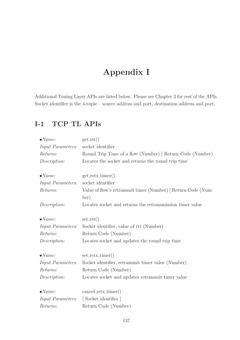
Appendix I
Additional Tuning Layer APIs are listed below. Please see Chapter 3 for rest of the APIs.
Socket identifier is the 4-tuple – source address and port, destination address and port.
I-1 TCP TL APIs
•Name: get rtt()
Input Parameters: socket identifier
Returns: Round Trip Time of a flow (Number) | Return Code (Number)
Description: Locates the socket and returns the round trip time
•Name: get retx timer()
Input Parameters: socket identifier
Returns: Value of flow’s retransmit timer (Number) | Return Code (Num-
ber)
Description: Locates socket and returns the retransmission timer value
•Name: set rtt()
Input Parameters: Socket identifier, value of rtt (Number)
Returns: Return Code (Number)
Description: Locates socket and updates the round trip time
•Name: set retx timer()
Input Parameters: Socket identifier, retransmit timer value (Number)
Returns: Return Code (Number)
Description: Locates socket and updates retransmit timer value
•Name: cancel retx timer()
Input Parameters: [ Socket identifier ]
Returns: Return Code (Number)
137

138 CHAPTER 8. SUMMARY AND CONCLUSIONS
Description: Locates socket(s) and cancels the retransmit timer. If no socket
identifier is specified then the timers of all the TCP flows are
canceled.
•Name: enable retx timer()
Input Parameters: [ Socket identifier ], timer value (Number)
Returns: Return Code (Number)
Description: Locates socket(s) and restarts the retransmit timer, with the
specified value. If no socket identifier is specified then the timers
of all the TCP flows are restarted with the specified value.
I-2 Mobile-IP TL APIs
•Name: get solicitation timer()
Input Parameters: –
Returns: Timer (Number) | Return Code (Number)
Description: Returns the solicitation timer
•Name: get current solicitations()
Input Parameters: –
Returns: Solicitations (Number) | Return Code (Number)
Description: Returns the number of solicitations sent
•Name: get max solicitation interval()
Input Parameters: –
Returns: Max interval (Number) | Return Code (Number)
Description: Returns the maximum solicitation interval
•Name: set solicitation timer()
Input Parameters: Timer (Number)
Returns: Return Code (Number)
Description: Updates the solicitation timer
•Name: set current solicitations()
Input Parameters: Solicitations (Number)
Returns: Return Code (Number)
Description: Updates the number of solicitations sent
•Name: set max solicitation interval()
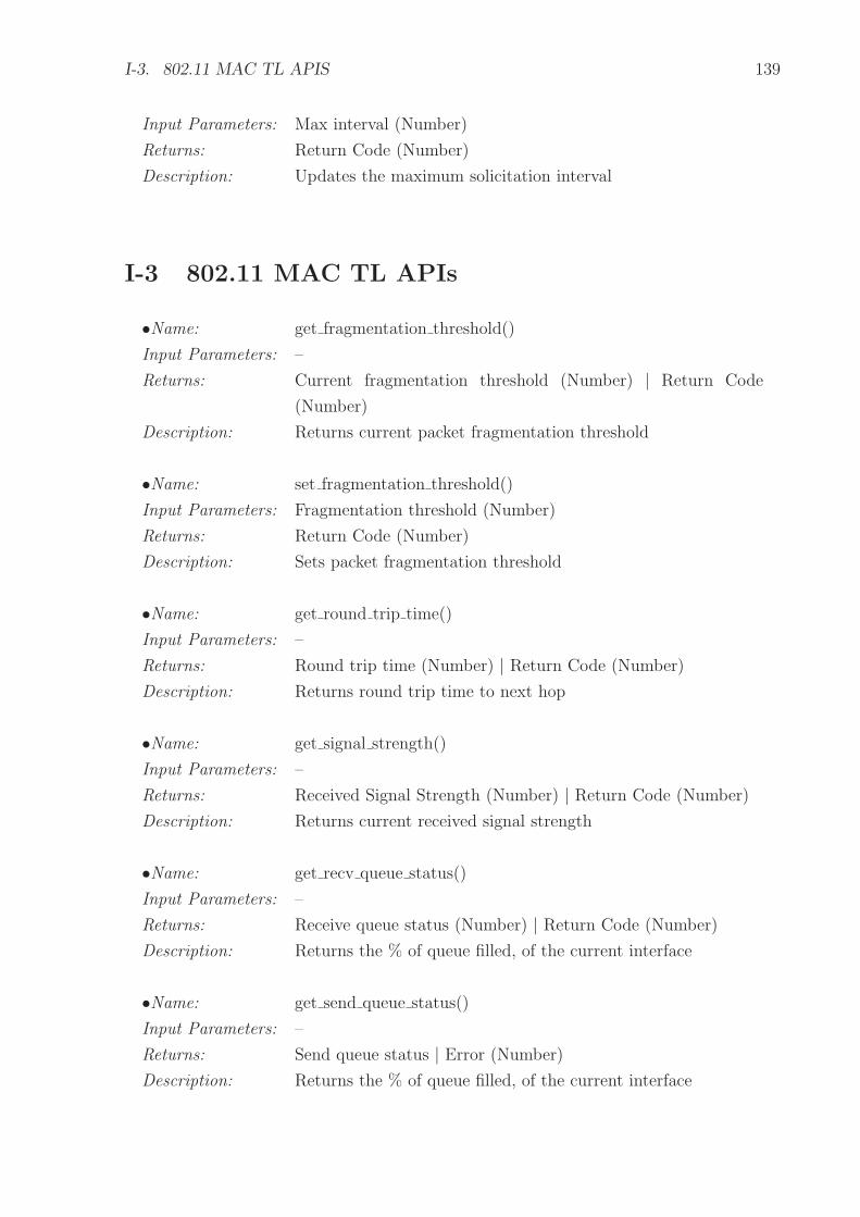
I-3. 802.11 MAC TL APIS 139
Input Parameters: Max interval (Number)
Returns: Return Code (Number)
Description: Updates the maximum solicitation interval
I-3 802.11 MAC TL APIs
•Name: get fragmentation threshold()
Input Parameters: –
Returns: Current fragmentation threshold (Number) | Return Code
(Number)
Description: Returns current packet fragmentation threshold
•Name: set fragmentation threshold()
Input Parameters: Fragmentation threshold (Number)
Returns: Return Code (Number)
Description: Sets packet fragmentation threshold
•Name: get round trip time()
Input Parameters: –
Returns: Round trip time (Number) | Return Code (Number)
Description: Returns round trip time to next hop
•Name: get signal strength()
Input Parameters: –
Returns: Received Signal Strength (Number) | Return Code (Number)
Description: Returns current received signal strength
•Name: get recv queue status()
Input Parameters: –
Returns: Receive queue status (Number) | Return Code (Number)
Description: Returns the % of queue filled, of the current interface
•Name: get send queue status()
Input Parameters: –
Returns: Send queue status | Error (Number)
Description: Returns the % of queue filled, of the current interface

140 CHAPTER 8. SUMMARY AND CONCLUSIONS
•Name: get current bandwidth()
Input Parameters: –
Returns: Bandwidth (Number) | Error (Number)
Description: Returns the bandwidth of current interface
•Name: get packet errors()
Input Parameters: –
Returns: Received packet errors (Number) | Return Code (Number)
Description: Returns number of packets received with error
I-4 802.11 Phy TL APIs
•Name: get bit errors()
Input Parameters: –
Returns: Current bit error rate i.e. bits per 105 (Number) | Return Code
(Number)
Description: Returns the current bit error rate
•Name: get channel()
Input Parameters: –
Returns: Current channel (Number) | Return Code (Number)
Description: Returns currently selected channel for transmission
•Name: set channel()
Input Parameters: Transmit channel (Number)
Returns: Return Code (Number)
Description: Sets the transmission channel
•Name: get sensitivity threshold()
Input Parameters: –
Returns: Sensitivity Threshold (Number) | Return Code (Number)
Description: Returns the sensitivity threshold
•Name: set sensitivity threshold()
Input Parameters: Sensitivity Threshold (Number)
Returns: Return Code (Number)
Description: Updates the sensitivity threshold

I-4. 802.11 PHY TL APIS 141
•Name: get noise level()
Input Parameters: –
Returns: Noise level (Number) | Return Code (Number)
Description: Returns the current noise level

142
This page has been intentionally left blank

Bibliography
[1] A.H. Aghvami, T.H. Le, and N. Olaziregi. Mode Switching and QoS Issues in
Software Radio. IEEE Personal Communications, 8(5):38–44, October 2001.
[2] P. Agrawal, S. Chen, P. Ramanathan, and K. Sivalingam. Battery Power Sensitive
Video Processing in Wireless Networks. In IEEE PIMRC, Boston, September 1998.
[3] A. Alwan, R. Bagrodia, N. Bambos, M. Gerla, L. Kleinrock, J. Short, and J. Vil-
lasenor. Adaptive Mobile Multimedia Networks. IEEE Personal Communications,
3(2):34–51, April 1996.
[4] Pablo Neira Ayuso and Laurent Lefevre. NETLinkBench : Netlink Socket Bench-
mark Tool. http://perso.ens-lyon.fr/laurent.lefevre/software/netlinkbench/, 2005.
[5] B. Badrinath, A. Fox, L. Kleinrock, G. Popek, P. Reiher, and M. Satyanarayanan.
A Conceptual Framework for Network and Client Adaptation. Mobile Networks and
Applications, 5(4):221–231, 2000.
[6] Ajay Bakre and B. R. Badrinath. I-TCP: Indirect TCP for Mobile Hosts. 15th
International Conference on Distributed Computing Systems, 1994.
[7] H. Balakrishnan, V. N. Padmanabhan, S. Seshan, and R. H. Katz. A Comparison
of Mechanisms for Improving TCP Performance over Wireless Links. IEEE/ACM
Transactions on Networking, 5(6):756–769, December 1997.
[8] Hari Balakrishnan, Srinivasan Seshan, and Randy H. Katz. Improving Reliable
Transport and Handoff Performance in Cellular Wireless Networks. ACM Wireless
Networks, 1(4), 1995.
[9] PerOlof Bengtsson, Nico Lassing, Jan Bosch, and Hans van Vliet. Architecture-level
modifiability analysis (ALMA). Journal of Systems and Software, 69(1-2):129–147,
2004.
[10] Pravin Bhagwat, Partha Bhattacharya, Arvind Krishna, and Satish K. Tripathi.
Using Channel State Dependent Packet Scheduling to Improve TCP Throughput
over Wireless LANs. Wireless Networks, 3(1):91–102, 1997.
143
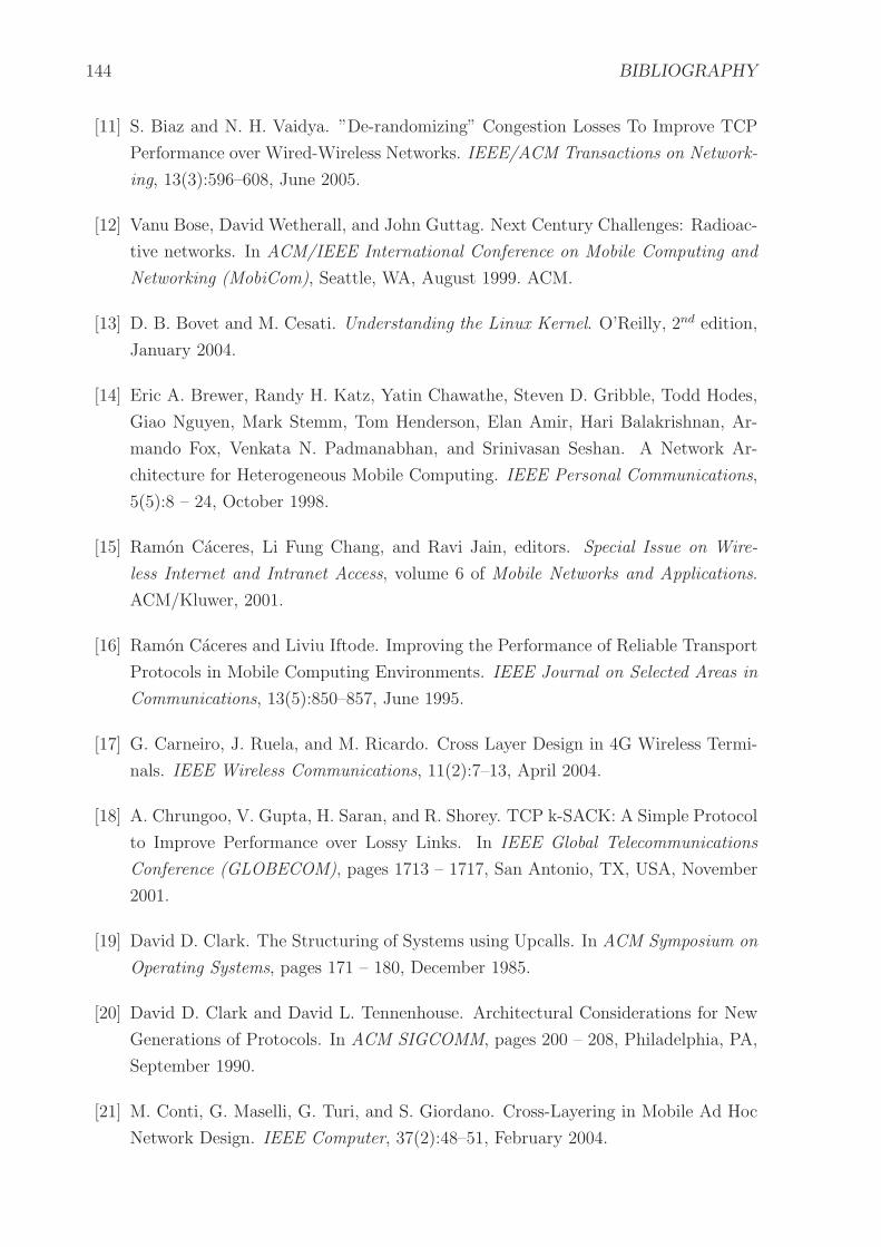
144 BIBLIOGRAPHY
[11] S. Biaz and N. H. Vaidya. ”De-randomizing” Congestion Losses To Improve TCP
Performance over Wired-Wireless Networks. IEEE/ACM Transactions on Network-
ing, 13(3):596–608, June 2005.
[12] Vanu Bose, David Wetherall, and John Guttag. Next Century Challenges: Radioac-
tive networks. In ACM/IEEE International Conference on Mobile Computing and
Networking (MobiCom), Seattle, WA, August 1999. ACM.
[13] D. B. Bovet and M. Cesati. Understanding the Linux Kernel. O’Reilly, 2nd edition,
January 2004.
[14] Eric A. Brewer, Randy H. Katz, Yatin Chawathe, Steven D. Gribble, Todd Hodes,
Giao Nguyen, Mark Stemm, Tom Henderson, Elan Amir, Hari Balakrishnan, Ar-
mando Fox, Venkata N. Padmanabhan, and Srinivasan Seshan. A Network Ar-
chitecture for Heterogeneous Mobile Computing. IEEE Personal Communications,
5(5):8 – 24, October 1998.
[15] Ramon Caceres, Li Fung Chang, and Ravi Jain, editors. Special Issue on Wire-
less Internet and Intranet Access, volume 6 of Mobile Networks and Applications.
ACM/Kluwer, 2001.
[16] Ramon Caceres and Liviu Iftode. Improving the Performance of Reliable Transport
Protocols in Mobile Computing Environments. IEEE Journal on Selected Areas in
Communications, 13(5):850–857, June 1995.
[17] G. Carneiro, J. Ruela, and M. Ricardo. Cross Layer Design in 4G Wireless Termi-
nals. IEEE Wireless Communications, 11(2):7–13, April 2004.
[18] A. Chrungoo, V. Gupta, H. Saran, and R. Shorey. TCP k-SACK: A Simple Protocol
to Improve Performance over Lossy Links. In IEEE Global Telecommunications
Conference (GLOBECOM), pages 1713 – 1717, San Antonio, TX, USA, November
2001.
[19] David D. Clark. The Structuring of Systems using Upcalls. In ACM Symposium on
Operating Systems, pages 171 – 180, December 1985.
[20] David D. Clark and David L. Tennenhouse. Architectural Considerations for New
Generations of Protocols. In ACM SIGCOMM, pages 200 – 208, Philadelphia, PA,
September 1990.
[21] M. Conti, G. Maselli, G. Turi, and S. Giordano. Cross-Layering in Mobile Ad Hoc
Network Design. IEEE Computer, 37(2):48–51, February 2004.

BIBLIOGRAPHY 145
[22] Geoffrey H. Cooper. The Argument for Soft Layer of Protocols. Technical Report
TR-300, Massachusetts Institute of Technology, Cambridge, MA, May 1983.
[23] Jonathan Corbet, Alessandro Rubini, and Greg Kroah Hartman. Linux Device
Drivers. O’Reilly, February 2005. Third edition.
[24] C.D.A. Cordeiro, S.R. Das, and D.P. Agrawal. COPAS: Dynamic Contention-
Balancing to Enhance the Performance of TCP over Multi-hop Wireless Networks.
In International Conference on Computer Communications and Networks, pages
382 – 387, Miami, October 2002.
[25] A. DeSimone, M. Chuah, and O. Yue. Throughput Performance of Transport-layer
Protocols Over Wireless Lans. In IEEE GLOBECOM, December 1993.
[26] Jean-Pierre Ebert and Adam Wolisz. Combined Tuning of RF power and Medium
Access Control for WLANs. Mobile Networks and Applications, 6(5):417–426, 2001.
Special issue on Mobile Multimedia Communications (MoMuC ’99).
[27] Yue Fang and A.B McDonald. Cross-layer Performance Effects of Path Coupling
in Wireless Ad hoc Networks: Power and Throughput Implications of IEEE 802.11
MAC. In 21st IEEE International Performance, Computing, and Communications
Conference, pages 281–290, 2002.
[28] W. Feng, M. Gardner, and J. Hay. The MAGNeT Toolkit: Design, Evaluation, and
Implementation. Journal of Supercomputing, 23(1):67–79, August 2002.
[29] T. Goff, J. Moronski, D.S. Pathak, and V. Gupta. Freeze-TCP: A true end-to-end
Enhancement Mechanism for Mobile Environments. In IEEE INFOCOM, Israel,
2000.
[30] A.J. Goldsmith and S.B. Wicker. Design Challenges for Energy-constrained Ad hoc
Wireless Networks. IEEE Wireless Communications, 9(4):8–27, August 2002.
[31] Zygmunt J. Haas, editor. Design Methodologies for Adaptive and Multimedia Net-
works, volume 39 of IEEE Communications Magazine. IEEE Communications So-
ciety, November 2001.
[32] Gavin Holland, Nitin Vaidya, and Paramvir Bahl. A Rate-Adaptive MAC Protocol
for Multi-Hop Wireless Networks. In MobiCom ’01: Proceedings of the 7th Annual
International Conference on Mobile Computing and Networking, pages 236–251,
New York, NY, USA, 2001. ACM Press.
[33] IEEE Std 802.11-1997. Wireless LAN Medium Access Control (MAC) And Physical
Layer (PHY) Specifications, 18 November 1997.

146 BIBLIOGRAPHY
[34] Jon Inouye, Jim Binkley, and Jonathan Walpole. Dynamic Network Reconfiguration
Support for Mobile Computers. In ACM/IEEE International Conference on Mobile
Computing and Networking (MobiCom), Budapest, Hungary, September 26 – 30
1997.
[35] ITU. Information technology - OSI - Basic Reference Model, July 1994. X.200.
[36] P. Jalote. An Integrated Approach to Software Engineering. Springer Verlag New
York, 1997. Second Edition.
[37] A. Jamalipour and S. Tekinay, editors. Fourth Generation Wireless Networks and
Interconnecting Standards, volume 8 of IEEE Personal Communications. October
2001.
[38] Christine E. Jones, Krishna M. Sivalingam, Prathima Agrawal, and Jyh Cheng
Chen. A Survey of Energy Efficient Network Protocols for Wireless Networks. Wire-
less Networks, 7(4):343–358, 2001.
[39] A. Kamerman and L. Monteban. WaveLAN II: A High-performance Wireless LAN
for the Unlicensed Band. Bell Labs Technical Journal, Summer:118–133, 1997.
[40] Shigeru Kashihara, Katsuyoshi Iida, Hiroyuki Koga, Youki Kadobayashi, and Sug-
uru Yamaguchi. Multi-path Transmission Algorithm for End-to-End Seamless Han-
dover across Heterogeneous Wireless Access Networks. In Samir R. Das and Sajal K.
Das, editors, IWDC, volume 2918 of Lecture Notes in Computer Science, pages 174–
183. Springer, 2003.
[41] V. Kawadia and P. R. Kumar. A Cautionary Perspective on Cross Layer Design.
IEEE Wireless Communications, 12(1):3–11, February 2005.
[42] Brian W. Kernighan, Dennis Ritchie, and Dennis M. Ritchie. The C Programming
Language. Prentice Hall PTR, 2nd edition, 1998.
[43] S.L. Kota, E. Hossain, R. Fantacci, and A. Karmouch. Cross-Layer Protocol En-
gineering for Wireless Mobile Networks (Guest Editorial). IEEE Communications
Magazine. Spl. Issue – Cross Layer Protocol Engineering, 43(12):110–111, December
2005.
[44] Robin Kravets and P. Krishnan. Application-driven Power Management for Mobile
Communication. Wireless Networks, 6(4):263–277, 2000.
[45] Mathieu Lacage, Mohammad Hossein Manshaei, and Thierry Turletti. IEEE 802.11
Rate Adaptation: A Practical Approach. In MSWiM ’04: Proceedings of the 7th

BIBLIOGRAPHY 147
ACM International Symposium on Modeling, Analysis and Simulation of Wireless
and Mobile Systems, pages 126–134, New York, NY, USA, 2004. ACM Press.
[46] P. Lettieri, C. Fragouli, and M. B. Srivastava. Low Power Error Control for Wireless
Links. In MobiCom, pages 139–150, Budapest, Hungary, September 1997. Also in
WINET 5 (1999).
[47] Paul Lettieri and Mani B. Srivastava. Adaptive Frame Length Control for Improving
Wireless Link Throughput, Range and Energy Efficiency. In INFOCOM (2), pages
564–571, March 1998.
[48] Y. Bing Lin, H. Rao, and I. Chlamtac. General Packet Radio Service (GPRS):
Architecture, Interfaces, and Deployment. Journal of Wireless Communications
and Mobile Computing, 1(1):77–92, 2001.
[49] Hang Liu and Magda El Zarki. Adaptive Source Rate Control for Real-time Wireless
Video Transmission. Mobile Networks and Applications, 3(1):49–60, 1998.
[50] Reiner Ludwig, Almudena Konrad, Anthony D. Joseph, and Randy H. Katz. Opti-
mizing the End-to-End Performance of Reliable Flows over Wireless Links. Wireless
Networks, 8(2–3):289 – 299, March–May 2002.
[51] Chung-Horng Lung, Sonia Bot, Kalai Kalaichelvan, and Rick Kazman. An Approach
to Software Architecture Analysis for Evolution and Reusability. In CASCON ’97:
Proceedings of the 1997 Conference of the Centre for Advanced Studies on Collabo-
rative research, page 15. IBM Press, 1997.
[52] M. Allman and V. Paxson and W. Stevens. RFC2581: TCP Congestion Control,
April 1999.
[53] David A. Maltz, Josh Broch, and David B. Johnson. Lessons from a Full-Scale
Multihop Wireless Ad Hoc Network Testbed. IEEE Personal Communications,
8:8–15, February 2001.
[54] P. Mehra, A. Zakhor, and C. Vleeschouwer. Receiver-Driven Bandwidth Sharing
for TCP. In IEEE INFOCOM, SF, USA, April 2003.
[55] Michael Methfessel, Kai F. Dombrowski, Peter Langendorfer, Horst Frankenfeldt,
Irina Babanskaja, Irina Matthaei, and Rolf Kraemer. Vertical Optimization of
Data Transmission for Mobile Wireless Terminals. IEEE Wireless Communications,
9(6):36–43, 2002.

148 BIBLIOGRAPHY
[56] Brian D. Noble, M. Satyanarayanan, Dushyanth Narayanan, James Eric Tilton,
Jason Flinn, and Kevin R. Walker. Agile Application-Aware Adaptation for Mo-
bility. In 16th ACM Symposium on Operating System Principles, St. Malo, France,
October 1997. ACM.
[57] The network simulator ns-2. http://www.isi.edu/nsnam/ns/,.
[58] Kostas Pentikousis. TCP in Wired-cum-Wireless Environments. IEEE Communi-
cations Surveys & Tutorials, 3(4):2–14, 2000.
[59] C Perkins. IP Mobility Support for IPv4. RFC3344, August 2002.
[60] Dhananjay S. Phatak and Tom Goff. A Novel Mechanism for Data Streaming
Across Multiple IP Links for Improving Throughput and Reliability in Mobile En-
vironments. In IEEE INFOCOM, volume 21, pages 773–781, June 2002.
[61] J. Postel. Transmission Control Protocol. RFC 793, September 1981.
[62] R. S. Pressman. Software Engineering, A Practitioner’s Approach. McGraw-Hill,
4th edition, 1997.
[63] John G. Proakis, Joseph A. Rice, and Milica Stojanovic. Shallow Water Acoustic
Networks. In Haas [31], pages 114–119.
[64] V. T. Raisinghani and S. Iyer. User Managed Wireless Protocol Stacks. 23rd ICDCS,
2003. Poster.
[65] V. T. Raisinghani and S. Iyer. Cross-layer Design Optimizations in Wireless Protocol
Stacks. Computer Communications (Elsevier), 27(8):720–724, May 2004.
[66] V. T. Raisinghani, A. K. Singh, and S. Iyer. Improving TCP Performance over
Mobile Wireless Environments using Cross Layer Feedback. In IEEE ICPWC, New
Delhi, India, December 2002.
[67] A. Sanmateu, F. Paint, L. Morand, S. Tessier, P. Fouquart, A. Sollund, and E. Bus-
tos. Seamless Mobility across IP Networks using Mobile IP. Computer Networks,
40(1):181–190, September 2002.
[68] Ajay Kr. Singh and Sridhar Iyer. ATCP: Improving TCP Performance over Mo-
bile Wireless Environments. In Fourth IEEE Conference on Mobile and Wireless
Communications Networks, Stockholm, Sweden, September 2002.
[69] N.T. Spring, M. Chesire, M. Berryman, V.Sahasranaman, T. Anderson, and B. Ber-
shad. Receiver Based Management of Low Bandwidth Access Links. In INFOCOM,
2000.

BIBLIOGRAPHY 149
[70] W. Richard Stevens. TCP/IP Illustrated, Volume I, The Protocols. AWL, 1994.
[71] W. Richard Stevens, Bill Fenner, and Andrew M. Rudoff. UNIX Network Program-
ming, volume 1. Prentice Hall PTR, 3rd edition, 2003.
[72] R. Stewart, Q. Xie, K. Morneault, C. Sharp, H. Schwarzbauer, T. Taylor, I. Rytina,
M. Kalla, L. Zhang, and V. Paxson. Stream Control Transmission Protocol. http:
//www.ietf.org/rfc/rfc2960.txt, 2000.
[73] P. Sudame and B. R. Badrinath. On Providing Support for Protocol Adaptation in
Mobile Networks. Mobile Networks and Applications, 6(1):43–55, 2001.
[74] Andrew S. Tanenbaum. Computer Networks. Prentice-Hall, 3 edition, 1996.
[75] Ye Tian, Kai Xu, and N. Ansari. TCP in Wireless Environments: Problems and
Solutions. IEEE Communications Magazine, 43(3):S27–S32, March 2005.
[76] UMTS Forum. Glossary. http://www.umts-forum.org/glossary.asp, 2003.
[77] Andrs G. Valk. Cellular IP: A New Approach to Internet Host Mobility. ACM
SIGCOMM Computer Communication Review, 29(1):50–65, 1999.
[78] Von Welch. A User’s Guide to TCP Windows. http://archive.ncsa.uiuc.edu/
People/vwelch/net\_perf/tcp\_windows.html, 1996.
[79] Qi Wang and M.A. Abu-Rgheff. Cross-layer Signalling for Next-Generation Wireless
Systems. In Wireless Communications and Networking (WCNC), volume 2, pages
1084–1089. IEEE, March 2003.
[80] Larry J. Williams. Technology Advances from Small Unit Operations Situation
Awareness System Development. IEEE Personal Communications, 8:30–33, Febru-
ary 2001.
[81] Gang Wu, Yong Bai, Jie Lai, and A. Ogielski. Interactions between TCP and RLP
in Wireless Internet. In IEEE GLOBECOM, volume 1B, pages 661–666, Rio de
Janeiro, Brazil, December 1999. IEEE.
[82] Jon Chiung-Shien Wu, Chieh-Wen Cheng, Nen-Fu Huang, and Gin-Kou Ma. Intel-
ligent Handoff for Mobile Wireless Internet. In Caceres et al. [15].
[83] Haizhi Xu, Wenliang Du, and Steve J. Chapin. Detecting exploit code execution in
loadable kernel modules. In ACSAC ’04: Proceedings of the 20th Annual Computer
Security Applications Conference (ACSAC’04), pages 101–110, Washington, DC,
USA, 2004. IEEE Computer Society.

150 BIBLIOGRAPHY
[84] K. Xu, Y. Tian, and N. Ansari. TCP-Jersey for Wireless IP Communications. IEEE
Journal on Selected Areas in Communications, 22(4):747–56, May 2004.
[85] G. Xylomenos and G. C. Polyzos. Internet Protocol Performance over Networks
with Wireless Links. IEEE Network, 13(4):55 – 63, July-August 1999.
[86] George Xylomenos and George C. Polyzos. Quality of Service Support over Multi-
Service Wireless Internet Links. Computer Networks, 37(5):601–615, 2001.
[87] Karim Yaghmour and Michel R. Dagenais. Measuring and Characterizing System
Behavior Using Kernel-Level Event Logging. In 2000 USENIX Annual Technical
Conference, San Diego, California, USA, June 2000.
[88] W Yuan, K Nahrstedt, S Adve, D Jones, and R Kravets. Design and Evaluation of A
Cross-Layer Adaptation Framework for Mobile Multimedia Systems. In SPIE/ACM
Multimedia Computing and Networking Conference (MMCN), Santa Clara, CA,
2003.
[89] M. Zorzi and R.R. Rao. Perspectives on the Impact of Error Statistics on Protocols
for Wireless Networks. IEEE Personal Communications, 6(5):32–40, October 1999.
[90] Craig’s ACX100/111 Guide for Linux. http://www.houseofcraig.net/acx100 howto.php,
2005.
[91] The ACX100/ACX111 Wireless Network Driver Project.
http://acx100.sourceforge.net, 2004. version 0.20pre8.
[92] Cbrowser. http://cbrowser.sourceforge.net/.
[93] Cross referencing linux. http://lxr.linux.no/source/.
[94] Cscope. http://cscope.sourceforge.net/.
[95] Gowri Dhandapani and Anupama Sundaresan. Netlink Sockets – Overview.
http://qos.ittc.ku.edu/netlink/netlink.ps, 1999.
[96] D-link. http://www.dlink.com, 2005.
[97] Dynamics Mobile IP. http://dynamics.sourceforge.net/, 2005.
[98] Kevin He. Kernel Korner - Why and How to Use Netlink Socket.
http://www.linuxjournal.com/, 2005.
[99] Linux. http://linux.org, 2005.

BIBLIOGRAPHY 151
[100] The Linux Kernel Archives (IIT Bombay (mirror site).
ftp://ftp.iitb.ac.in/linux/kernel/v2.4/, 2005.
[101] The Linux Kernel Archives. http://www.kernel.org, 2005.
[102] Linux Trace Toolkit (LTT). http://www.opersys.com/LTT/index.html, 2005.
[103] Monitoring Apparatus for General kerNel Event Tracing (MAGNET).
http://public.lanl.gov/radiant/research/measurement/magnet.html, 2005.
[104] NetBSD. http://netbsd.org, 2005.
[105] OProfile. http://oprofile.sourceforge.net, 2005.
[106] The UNIX System. http://www.unix.org, 2005.
[107] Wget. http://www.gnu.org/software/wget/wget.html, 2005.

152
This page has been intentionally left blank
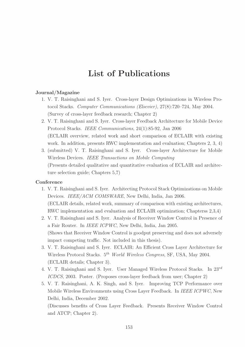
List of Publications
Journal/Magazine
1. V. T. Raisinghani and S. Iyer. Cross-layer Design Optimizations in Wireless Pro-
tocol Stacks. Computer Communications (Elsevier), 27(8):720–724, May 2004.
(Survey of cross-layer feedback research; Chapter 2)
2. V. T. Raisinghani and S. Iyer. Cross-layer Feedback Architecture for Mobile Device
Protocol Stacks. IEEE Communications, 24(1):85-92, Jan 2006
(ECLAIR overview, related work and short comparison of ECLAIR with existing
work. In addition, presents RWC implementation and evaluation; Chapters 2, 3, 4)
3. (submitted) V. T. Raisinghani and S. Iyer. Cross-layer Architecture for Mobile
Wireless Devices. IEEE Transactions on Mobile Computing
(Presents detailed qualitative and quantitative evaluation of ECLAIR and architec-
ture selection guide; Chapters 5,7)
Conference
1. V. T. Raisinghani and S. Iyer. Architecting Protocol Stack Optimizations on Mobile
Devices. IEEE/ACM COMSWARE, New Delhi, India, Jan 2006.
(ECLAIR details, related work, summary of comparison with existing architectures,
RWC implementation and evaluation and ECLAIR optimization; Chapterss 2,3,4)
2. V. T. Raisinghani and S. Iyer. Analysis of Receiver Window Control in Presence of
a Fair Router. In IEEE ICPWC, New Delhi, India, Jan 2005.
(Shows that Receiver Window Control is goodput preserving and does not adversely
impact competing traffic. Not included in this thesis).
3. V. T. Raisinghani and S. Iyer. ECLAIR: An Efficient Cross Layer Architecture for
Wireless Protocol Stacks. 5th World Wireless Congress, SF, USA, May 2004.
(ECLAIR details; Chapter 3).
4. V. T. Raisinghani and S. Iyer. User Managed Wireless Protocol Stacks. In 23rd
ICDCS, 2003. Poster. (Proposes cross-layer feedback from user; Chapter 2)
5. V. T. Raisinghani, A. K. Singh, and S. Iyer. Improving TCP Performance over
Mobile Wireless Environments using Cross Layer Feedback. In IEEE ICPWC, New
Delhi, India, December 2002.
(Discusses benefits of Cross Layer Feedback. Presents Receiver Window Control
and ATCP; Chapter 2).
153

154
This page has been intentionally left blank

Acknowledgment
It is not easy to express gratitude in words for my thesis advisor Prof. Sridhar Iyer. I am
indebted to him for constantly guiding and encouraging me, even before I registered for
PhD. His clarity of thought and unambiguous directions right from problem search and
definition to the writing stage ensured that I stayed on track. I am amazed that he could
quickly recollect and continue the analysis of my problem even after a gap of many weeks
and many other student discussions. I must thank him for his patience and tolerance for
my personal and professional requirements. His advice helped me not only with my thesis
but also with life in general.
I am obliged to TATA Infotech Ltd. for sponsoring my PhD. I must thank Dr. Arun
Pande (GM, Technology) for his understanding of the PhD process and allowing me to
manage TIL’s lab in IIT. I thank him for participating in the initial reviews in spite of his
hectic schedule. I also thank Dr. Nirmal Jain (ex-MD) for approving my PhD application.
I am thankful to my PhD Committee, Prof. Abhay Karandikar and Prof. Anirudha
Sahoo (and also Prof. Krishna Paul), for evaluating my progress and providing valuable
inputs for enhancing the thesis.
My PhD colleagues (Prof. Iyer’s students) were quite helpful during the group meet-
ings. Their comments helped in critical evaluation of the initial ideas.
The KReSIT office staff were very helpful with the registration, fee payments and
other administration related formalities. Special mention must be made of Mr. Patil and
Mrs. Vijaya for making things quite comfortable in the RS-wing.
I also thank my colleagues at TIL, Pankaj Doke and Amit Pradhan, for helping me
manage the office workload.
I cannot thank enough my family, specially my mother(Bhagwanti) and wife(Deepa),
for helping me remain sane during the thesis. It was their constant efforts and encour-
agement at home that helped me maintain focus on my thesis. I am thankful to my elder
brother(Naresh) for his confidence boosting talks. My twin kids (Rashmi-Roshni) deserve
a big thank you, for teaching me to smile in the worst of situations and allowing me to
use the home computer for office work.
Vijay Thakurdas Raisinghani
(01429703)
155