Embed Size (px)
Citation preview
PHYSICAL REVIEW B 1 NOVEMBER 1998-IIVOLUME 58, NUMBER 18
Crossover between fractal and nonfractal flux penetration in high-temperaturesuperconducting thin films
R. Surdeanu, R. J. Wijngaarden, B. Dam, J. Rector, and R. GriessenInstitute COMPAS and Faculty of Physics and Astronomy, Vrije Universiteit, Amsterdam, De Boelelaan 1081,
1081 HV Amsterdam, The Netherlands
C. RosselIBM Research Division, Zurich Research Laboratory, 8803 Ru¨schlikon, Switzerland
Z. F. Ren and J. H. WangSuperconductive Materials Laboratory, Department of Chemistry and New York State Institute on Superconductivity,
State University of New York at Buffalo, Buffalo, New York 14260-3000~Received 28 October 1997; revised manuscript received 20 May 1998!
In this study the role ofanisotropyon flux penetration inc-axis epitaxial Tl2Ba2CuO61x and YBa2Cu3O72x
films is investigated by magneto-optics. We study thin films of Tl2Ba2CuO61x on substrates with vicinal anglesof 0° ~well-oriented!, 0.5°, 2.5°, and 4° and YBa2Cu3O72x films as a function of chain-conduction-inducedanisotropy. A crossover from fractal to nonfractal flux penetration is observed with increasing anisotropy.Numerical simulations of anisotropic flux motion are compared with experiment.@S0163-1829~98!05742-7#
nh-thle
inthn
icg.cab-
wte
ou
ectainwc
y
vi
ly
tryrys-
by
d-
ofandRe-I,hetalaronsheith
ltsa
-ioning
heat
I. INTRODUCTION
Magneto-optical~MO! investigations of magnetic fluxpenetration in high-Tc superconducting thin films show oftea flux front with a very irregular fractal shape even in higquality films.1–9 This behavior is in contrast with the smooand well-defined flux penetration observed in singcrystals1,2,10–17 and in some thin films.1,18,19 That the fluxpenetration in thin films is often more fractal-like thansingle crystals is rather surprising since the stability offlux front should increase for decreasing thickness, ahence be very stable in the thin-film case. From a technpoint of view, fractal flux penetration is undesirable in, e.thin-film devices since it may lead to increased electrinoise due to the irregular motion of the flux. Although oserved before,1–9 the irregular behavior of the flux front inthin films has not been studied from a fractal point of vieHowever, a fractal analysis of the superconducting clusnear Tc was done in YBa2Cu3O72x films.20 The notion offractal was introduced by B.B. Mandelbrot21 in 1967, whoshowed that it can be a useful concept in studying variphenomena appearing in nature.22,23 In this paper we study~i! the origin of the fractal behavior and~ii ! means to de-crease the irregularity of the flux front. In particular, wpresent a study of the crossover from fractal to nonfraflux penetration in thin films as a function of anisotropythe critical current density. This crossover is realized in tways; ~i! by introducing anisotropy in intrinsically isotropiTl2Ba2CuO61x films by means of a vicinal~stepped! sub-strate;~ii ! by introducing isotropic behavior in intrinsicallanisotropicab-oriented YBa2Cu3O72x films by means ofblocking the chain conduction. To our knowledge, all preous studies24 on anisotropicab-oriented thin films were doneon YBa2Cu3O72x on vicinal substrates.
The interest in Tl2Ba2CuO61x films was raised by the
PRB 580163-1829/98/58~18!/12467~11!/$15.00
edal,l
.rs
s
l
o
-
simplicity of their structure: tetragonal symmetry with onone CuO2 plane per unit cell and no CuO chain.25–30 Thisproperty suggested Tl2Ba2CuO61x to be an ideal candidatefor an unambiguous determination of the pairing symmein copper oxide superconductors, as was done in the trictal experiment by Tsuei and co-workers.26,31 Other experi-ments for determining the pairing symmetry were doneRosselet al.27 and Willeminet al.32 using a high-sensitivitycapacitive torque magnetometer technique on Tl2Ba2CuO61xthin films. Another reason of interest is the continuously ajustableTc over a large range of temperature, from 0 K up to85 K by varyingx.
This paper is organized as follows: a short descriptionthe high-resolution magneto-optical experimental setupof the sample preparation procedure is given in Sec. II.sults on Tl2Ba2CuO61x thin films are presented in Sec. IIbeginning with the well-oriented films and increasing tvicinal angle, observing the crossover from isotropic fracto anisotropic nonfractal behavior. Anisotropy in circulsamples is determined by comparison with the simulatidiscussed in Sec. IV. Guiding of the vortex motion by tvicinal steps is discussed in Sec. V and a comparison wthe anisotropic flux penetration in YBa2Cu3O72x thin films ismade in Sec. VI. In Sec. VII the various experimental resuare compared with numerical simulations exhibiting alsotransition from fractal to nonfractal behavior.
II. EXPERIMENT AND SAMPLE PREPARATION
Epitaxial Tl2Ba2CuO61x thin films are made by RF magnetron sputtering, followed by a two-step postdepositannealing.25 The sputtering source is prepared by pressand sintering an intimate mixture of Tl2O31 2BaO21 CuOwith twice preheating and an intermediate regriding. Tprecursor films are deposited by rf magnetron sputtering
12 467 ©1998 The American Physical Society
ae
aintoph
r
-ra-
are
as
e
o-
oluouley
nen
-nldn
et
er
aetu
oee
we
-
ofiseto-4.2. 2im-ter
nal
c.
e
the4.2ldof
12 468 PRB 58R. SURDEANUet al.
room temperature. The as-deposited films are then annein two steps, the last one in flowing argon, in order to ghigh-temperature superconducting epitaxial films. TheTc ofthe samples is about 83 K as determined resistively.
SrTiO3 platelets of typically 1031031 mm3 are used assubstrates. The normal to the platelet is either along the~001!direction or at a small angle, which is called the vicinangle. Films are sputtered on substrates with the followvicinal angles: 0°, 0.5°,2.5°, and 4°. The patterning inshapes of disks and squares is done using conventionaltolithography.
The YBa2Cu3O72x thin films are grown by pulsed lasedeposition~conditions as in Ref. 33! on ~001! NdGaO3 sub-strates and patterned by standard photolithography. Xdiffraction shows that the NdGaO3 substrates are well oriented (0° with an accuracy of 0.1°). In these YBa2Cu3O72x
films, thec axis is perpendicular to the substrate while theaandb axis have the same orientation over the whole film,verified by Rutherford backscattering and x-ray textuanalysis.34 These films will be denoted henceforthab-oriented YBa2Cu3O72x films. The chemical compositionof the films was investigated with secondary ion mass sptrometry ~SIMS!.35
As indicator for the local magnetic field in the magnetoptical experiments we use Bi-doped YIG films18 with in-plane anisotropy, which exhibit a large Faraday effect~typi-cally 0.03°/mT) and can be used for a large rangetemperatures, from 1.5 K up to 300 K. The magnetic resotion is better than 0.1 mT. The indicator is placed on topthe sample and the assembly is mounted in our home-bcryogenic polarization microscope, which is in the variabtemperature insert of an Oxford Instruments 1-T Magnet stem. The applied magnetic field is parallel with thec axis ofthe sample and perpendicular to the indicator. After the alyzer of the microscope, the spatial variation of the perpdicular component of the local inductionBz at the sample isgiven as an intensity pattern. The local fieldHz is determinedfrom the pattern using the calibrationI 5b f (Hz
2), whereI isthe intensity andb is a proportionality constant. The function f is determined in a separate calibration experimewhile b can be found by relating the intensity with the fieat a certain location in the image where the field is knowe.g., far away from the sample, where the local magnfield is equal to the applied external field.36 Images weretaken using a liquid-nitrogen-cooled ST-138 CCD Cam~Princeton Instruments!.
The temperature of the sample is measured with a cbrated RhFe thermometer. The light used for the magnoptical experiment causes a heating of the sample of abomK.
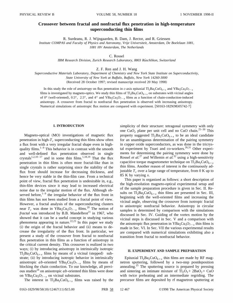
The vicinal angle of the substrates and the orientationthe a,b axis with respect to the edges of the substrates wchecked with x-ray Laue diffraction. From the Laue picturwe get two vicinal anglesg andw, referring to the deviationin two perpendicular planes, and one angleu, which indi-cates the misorientation of thea,b axis with respect to theedges of the substrates. Figure 1 depicts the angles, asas the total vicinal angled, which can be calculated using thformula
ledt
lg
o-
y
s
c-
f-filt
s-
a--
t,
,ic
a
li-o-t 1
fres
ell
d51
A11sin2g1sin2w, ~1!
whereg andw are the vicinal angles from the Laue diffraction image.
III. RESULTS ON Tl 2Ba2CuO61x THIN FILMS
A. 0° vicinal angle „well oriented…
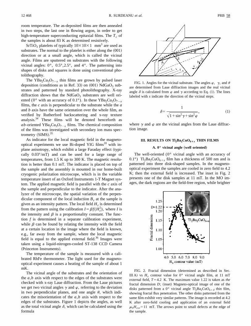
The well-oriented (0° vicinal angle with an accuracy0.1°) Tl2Ba2CuO61x film has a thickness of 500 nm andpatterned into three disk-shaped samples. In the magnoptical experiment the samples are cooled in zero field toK; then the external field is increased. The inset in Figpresents one of the disk samples at 11 mT. In the MOages, the dark regions are the field-free region, while brigh
FIG. 1. Angles for the vicinal substrate. The anglesw, g, anduare determined from Laue diffraction images and the real viciangled is calculated fromw andg according to Eq.~1!. The lineslabeled withs indicate the direction of the vicinal steps.
FIG. 2. Fractal dimension~determined as described in SeIII A ! vs Hz contour value for 0° vicinal angle film, at 11 mTexternal field,T54.2 K. The maximum value 1.22 is taken asthefractal dimensionD; ~inset! Magneto-optical image of one of thdisks patterned from a 0° vicinal angle Tl2Ba2CuO61d thin film,showing fractal flux penetration. The other disks patterned fromsame film exhibit very similar patterns. The image is recorded atK after zero-field cooling and application of an external fiem0Hext511 mT. The arrows point to small defects at the edgethe sample.
ae
unssn
ehn
eregis
igakhexe.heisi
de
d
isea
ploldnt
r.are
ra-cesthen,eak
islso
ofuchat
fluxles
ntos oftheex-
ee
ctsmpleatndi-ro-et canthe
n,
0°
ene
le: 3
rcle
llhethe
PRB 58 12 469CROSSOVER BETWEEN FRACTAL AND NONFRACTAL . . .
regions correspond to higher local fields. As for the Bemodel the vortex density and hence the local field are highat the sample edge and decrease towards its interiorthey vanish: the dark part of the sample is still in the Meiner state. The fractal flux penetration is not only evidefrom the flux front, but also from the flux density in thregion between the sample perimeter and the flux front. T‘‘flux scape’’ can be characterized by the fractal dimensioof contour lines taken at different values ofHz . To find thefractal dimension of a contour line, its perimeter is detmined using various yardsticks.22 The perimeter lengths arthen plotted as a function of the yardstick values, yieldinnearly straight line in a log-log plot. The slope of this lineby definition the fractal dimension. This slope and its 1serror bar are determined using a least-square fit to a straline. In our case the yardstick was the pixel size, and we tdifferent yardsticks by reducing the number of pixels in timage. If these fractal dimensions are plotted versus fivalues of the local fieldHz , a Lorentzian curve is obtainedAn example at an external field of 11 mT is shown in tgraph in Fig. 2. The width of the Lorentzian curve in thparticular case is 1 mT. The maximum of this Lorentzianused below asthe fractal dimensionD, while the contour inthe image corresponding to theHz value at the maximumwill be called flux front below.
In the remaining part of this section, we discuss thependence of the fractal dimensionD for the 0°-sample as afunction of external field. The dependence of the fractalmension on vicinal angle will be discussed in Sec. VII.
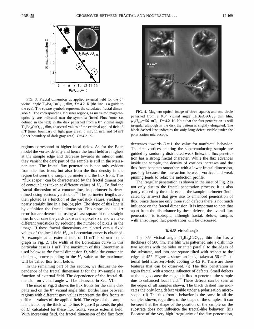
The inset in Fig. 3 shows the flux fronts for the same dpatterned on the 0° vicinal angle film. Border lines betweregions with different gray values represent the flux frontsdifferent values of the applied field. The edge of the samis indicated by the thick white line. Figure 3 presents the pof D, calculated for these flux fronts, versus external fieWith increasing field, the fractal dimension of the flux fro
FIG. 3. Fractal dimension vs applied external field for thevicinal angle Tl2Ba2CuO61d film, T54.2 K ~the line is a guide tothe eye!. The square symbols represent the calculated fractal dimsionD. The corresponding Meissner regions, as measured magoptically, are indicated near the symbols;~inset! Flux fronts ~asdefined in the text! in the disk patterned from a 0° vicinal angTl2Ba2CuO61x film, at several values of the external applied fieldmT ~inner boundary of light gray area!, 5 mT, 11 mT, and 14 mT~inner boundary of dark gray area!. T54.2 K.
nsttil-t
iss
-
a
hte
d
s
-
i-
knt
let.
decreases towardsD51, the value for nonfractal behavioThe first vortices entering the superconducting sampleguided by randomly distributed weak links; the flux penettion has a strong fractal character. While the flux advaninside the sample, the density of vortices increases andflux front becomes smoother, with a lower fractal dimensiopossibly because the interaction between vortices and wpinning tends to relax the induction profile.
The irregular penetration as shown in the inset of Fig. 2not only due to the fractal penetration process. It is apartly caused by three defects at the sample perimeter~indi-cated by arrows! that give rise to enhanced penetrationflux. Since there are only three such defects there is not minfluence on the fractal dimension. It is important to note thapart from the disturbance by these defects, the overallpenetration is isotropic, although fractal. Below, sampwith anisotropic flux penetration will be discussed.
B. 0.5° vicinal angle
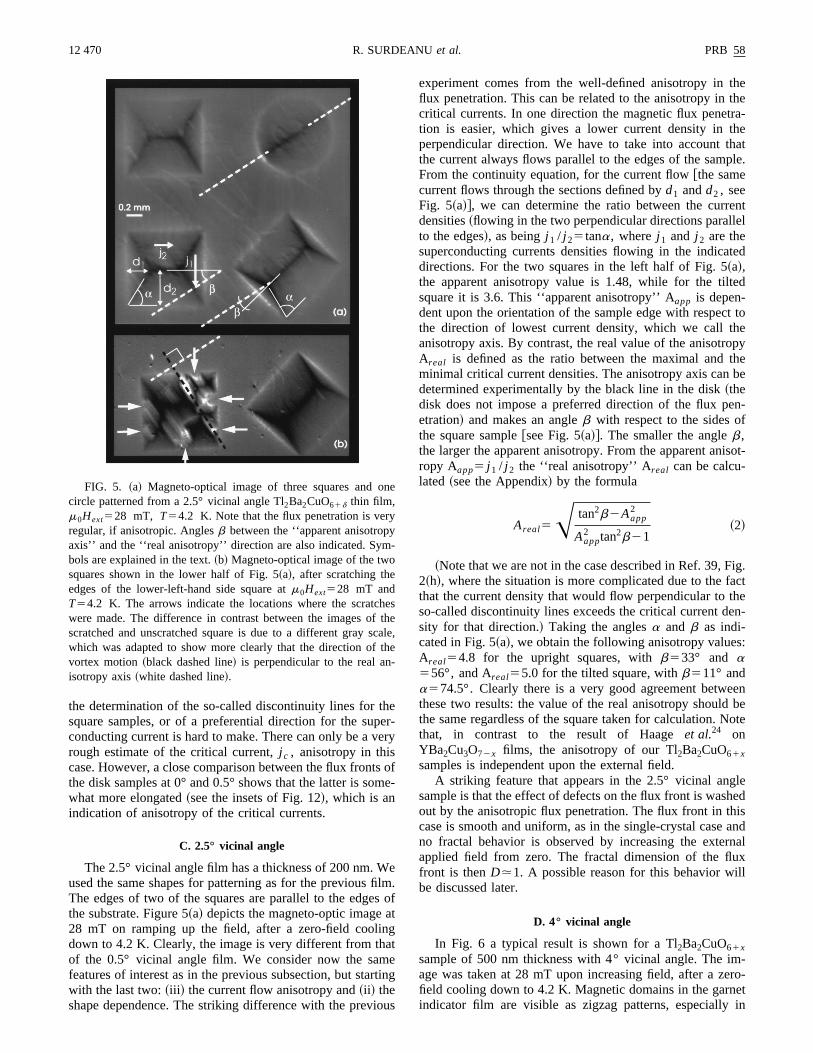
The 0.5° vicinal angle Tl2Ba2CuO61x thin film has athickness of 500 nm. The film was patterned into a disk, itwo squares with the sides oriented parallel to the edgethe substrate, and into one square tilted with respect toedges at 45°. Figure 4 shows an image taken at 56 mTternal field after zero-field cooling to 4.2 K. There are thrfeatures that can be observed.~i! The flux penetration isagain fractal with a strong influence of defects. Small defeat the edges cause the magnetic flux to penetrate the sadue to enhanced local field.37 These defects can be seenthe edges of all samples shown. The black dashed line icates the only long defect visible under a polarization micscope.~ii ! The flux front’s behavior is the same in all thsamples shown, regardless of the shape of the samples. Ibe seen that the shape or the position of the sample onsubstrate does not influence the fractal-like behavior.~iii !Because of the very high irregularity of the flux penetratio
n-to- FIG. 4. Magneto-optical image of three squares and one cipatterned from a 0.5° vicinal angle Tl2Ba2CuO61d thin film,m0Hext556 mT, T54.2 K. Note that the flux penetration is stiirregular although in the disk the pattern is slightly elongated. Tblack dashed line indicates the only long defect visible underpolarization microscope.
heee
tsm
efilsatngate
rti
io
thethera-hehatple.
entel
ted
ed
t toepy
thebe
en-f
isot-
ig.acttheen-
:
eenbeote
leedisandnalx
ll
-ro-etin
n
yy-
hef tcath-
12 470 PRB 58R. SURDEANUet al.
the determination of the so-called discontinuity lines for tsquare samples, or of a preferential direction for the supconducting current is hard to make. There can only be a vrough estimate of the critical current,j c , anisotropy in thiscase. However, a close comparison between the flux fronthe disk samples at 0° and 0.5° shows that the latter is sowhat more elongated~see the insets of Fig. 12!, which is anindication of anisotropy of the critical currents.
C. 2.5° vicinal angle
The 2.5° vicinal angle film has a thickness of 200 nm. Wused the same shapes for patterning as for the previousThe edges of two of the squares are parallel to the edgethe substrate. Figure 5~a! depicts the magneto-optic image28 mT on ramping up the field, after a zero-field coolidown to 4.2 K. Clearly, the image is very different from thof the 0.5° vicinal angle film. We consider now the samfeatures of interest as in the previous subsection, but stawith the last two:~iii ! the current flow anisotropy and~ii ! theshape dependence. The striking difference with the prev
FIG. 5. ~a! Magneto-optical image of three squares and ocircle patterned from a 2.5° vicinal angle Tl2Ba2CuO61d thin film,m0Hext528 mT, T54.2 K. Note that the flux penetration is verregular, if anisotropic. Anglesb between the ‘‘apparent anisotropaxis’’ and the ‘‘real anisotropy’’ direction are also indicated. Symbols are explained in the text.~b! Magneto-optical image of the twosquares shown in the lower half of Fig. 5~a!, after scratching theedges of the lower-left-hand side square atm0Hext528 mT andT54.2 K. The arrows indicate the locations where the scratcwere made. The difference in contrast between the images oscratched and unscratched square is due to a different gray swhich was adapted to show more clearly that the direction ofvortex motion~black dashed line! is perpendicular to the real anisotropy axis~white dashed line!.
r-ry
ofe-
m.of
ng
us
experiment comes from the well-defined anisotropy influx penetration. This can be related to the anisotropy incritical currents. In one direction the magnetic flux penettion is easier, which gives a lower current density in tperpendicular direction. We have to take into account tthe current always flows parallel to the edges of the samFrom the continuity equation, for the current flow@the samecurrent flows through the sections defined byd1 andd2 , seeFig. 5~a!#, we can determine the ratio between the currdensities~flowing in the two perpendicular directions parallto the edges!, as beingj 1 / j 25tana, wherej 1 and j 2 are thesuperconducting currents densities flowing in the indicadirections. For the two squares in the left half of Fig. 5~a!,the apparent anisotropy value is 1.48, while for the tiltsquare it is 3.6. This ‘‘apparent anisotropy’’ Aapp is depen-dent upon the orientation of the sample edge with respecthe direction of lowest current density, which we call thanisotropy axis. By contrast, the real value of the anisotroAreal is defined as the ratio between the maximal andminimal critical current densities. The anisotropy axis candetermined experimentally by the black line in the disk~thedisk does not impose a preferred direction of the flux petration! and makes an angleb with respect to the sides othe square sample@see Fig. 5~a!#. The smaller the angleb,the larger the apparent anisotropy. From the apparent anropy Aapp5 j 1 / j 2 the ‘‘real anisotropy’’ Areal can be calcu-lated ~see the Appendix! by the formula
Areal5A tan2b2Aapp2
Aapp2 tan2b21
~2!
~Note that we are not in the case described in Ref. 39, F2~h!, where the situation is more complicated due to the fthat the current density that would flow perpendicular toso-called discontinuity lines exceeds the critical current dsity for that direction.! Taking the anglesa and b as indi-cated in Fig. 5~a!, we obtain the following anisotropy valuesAreal54.8 for the upright squares, withb533° and a556°, and Areal55.0 for the tilted square, withb511° anda574.5°. Clearly there is a very good agreement betwthese two results: the value of the real anisotropy shouldthe same regardless of the square taken for calculation. Nthat, in contrast to the result of Haageet al.24 onYBa2Cu3O72x films, the anisotropy of our Tl2Ba2CuO61xsamples is independent upon the external field.
A striking feature that appears in the 2.5° vicinal angsample is that the effect of defects on the flux front is washout by the anisotropic flux penetration. The flux front in thcase is smooth and uniform, as in the single-crystal caseno fractal behavior is observed by increasing the exterapplied field from zero. The fractal dimension of the flufront is thenD.1. A possible reason for this behavior wibe discussed later.
D. 4° vicinal angle
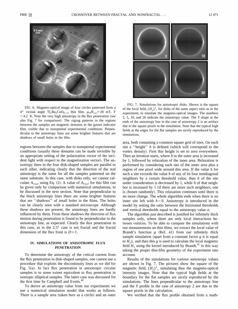
In Fig. 6 a typical result is shown for a Tl2Ba2CuO61xsample of 500 nm thickness with 4° vicinal angle. The image was taken at 28 mT upon increasing field, after a zefield cooling down to 4.2 K. Magnetic domains in the garnindicator film are visible as zigzag patterns, especially
e
shele,
e
nbci
leat
ca
torr
esugarfluth
ict
msfor
f
ws
ach
e.diss a
l
esno
lds
kbe-ithof
ic
to
esthel
hetheinehe
h-
a
scaen
a
arehebers
factighthe
PRB 58 12 471CROSSOVER BETWEEN FRACTAL AND NONFRACTAL . . .
regions between the samples due to nonoptimal experimeconditions~usually these domains can be made invisiblean appropriate setting of the polarization vector of the indent light with respect to the magnetization vector!. The an-isotropy lines in the four disk-shaped samples are paralleeach other, indicating clearly that the direction of the ranisotropy is the same for all the samples patterned onsame substrate. In this case, with disks only, we cannotculate Areal using Eq.~2!. A value of Areal for this film canbe given only by comparison with numerical simulations,be discussed in the next section. Note that perpendiculathe black anisotropy lines there are some brighter featuthat are ‘‘shadows’’ of small holes in the films. The holcan be clearly seen with a standard microscope. Althothese shadows are present, the anisotropy lines are hinfluenced by them. From these shadows the direction ofmotion during penetration is found to be perpendicular toanisotropy line, as expected. Clearly the flux penetrationthis case, as in the 2.5° case is not fractal and the fradimension of the flux front isD.1.
IV. SIMULATIONS OF ANISOTROPIC FLUXPENETRATION
To determine the anisotropy of the critical current frothe flux penetration in disk-shaped samples, one cannot uprocedure that exploits the discontinuity lines as we didFig. 5~a!. In fact flux penetration in anisotropic circulasamples is to some extent equivalent to flux penetrationisotropic elliptical samples. The latter case was discussedthe first time by Campbell and Evetts.40
To derive an anisotropy value from our experimentsuse a numerical simulation model that works as followThere is a sample area~taken here as a circle! and an outer
FIG. 6. Magneto-optical image of four circles patterned from4° vicinal angle Tl2Ba2CuO61d thin film, m0Hext528 mT, T54.2 K. Note the very high anisotropy in the flux penetration~seealso Fig. 7 for comparison!. The zigzag patterns in the regionbetween the samples are magnetic domains in the garnet indifilm, visible due to nonoptimal experimental conditions. Perpdicular to the anisotropy lines are some brighter features thatshadows of small holes in the film.
taly-
tol
hel-
toes
hdlyxenal
e ar
inor
e.
area, both containing a common square grid of sites. On esite a ‘‘height’’ h is defined~which will correspond to thevortex density!. First this height is set to zero everywherThen an iteration starts, whereh in the outer area is increaseby 1, followed by relaxation of the inner area. Relaxationperformed by considering each site of the inner area pluregion of one pixel wide around this area. If the valueh forsuch a site exceeds the valueh of any of its four nondiagonaneighbors by a certain threshold value, thenh of the siteunder consideration is decreased by 1, whileh of that neigh-bor is increased by 1~if there are more such neighbors, onis chosen randomly!. This relaxation continues until there ino more change. The whole algorithm ends when there isinner site left with h50. Anisotropy is introduced in themodel by setting the ratio between the horizontal threshoand vertical thresholds equal to the anisotropy valuea.
The algorithm just described is justified for infinitely thicsamples only, where there are only local interactionstween vortices. To be able to compare the simulations wour measurements on thin films, we extract the local valueBrandt’s function g ~Ref. 41! from our infinitely thicksample simulation~apart from a constant factorg it is equalto Hz), and then thisg is used to calculate the local magnetfield Hz using the kernel introduced by Brandt,41 in this waytaking the proper thin-film geometry of the experiment inaccount.
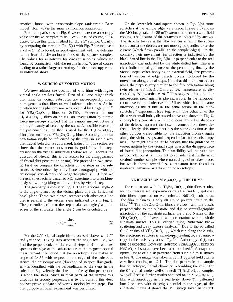
Results of the simulations for various anisotropy valuare shown in Fig. 7. The pictures show the square ofmagnetic field, (Hz)
2, simulating thus the magneto-opticaintensity images. Note that the typical high fields at tboundary for the flat samples are nicely reproduced bysimulations. The lines perpendicular to the anisotropy land theY profile in the case of anisotropy 2 are due to tsquare pixels in the calculation.
We verified that the flux profile obtained from a mat
tor-re
FIG. 7. Simulations for anisotropic disks. Shown is the squof the local field, (Hz)
2, for disks of the same aspect ratio as in texperiment, to simulate the magneto-optical images. The num2, 5, 10, and 20 indicate the anisotropy value. TheY shape at theends of the anisotropy line in the case of anisotropy 2 is an artidue to the square pixels in the simulation. Note that the typical hfields at the edges for the flat samples are nicely reproduced bysimulations.
p
rl
i-ler
rslu
ek
ori
en
waw
ep
n.ubth
ig
tal
retia
at-heiotheo
ldws.er-the
la
hetra-heionng-rer
-
. 6,owsde-the
opyofncet
ce,to
he
hic
leck-
sot-
wnr alefor
themT
12 472 PRB 58R. SURDEANUet al.
ematical funnel with anisotropic slope~anisotropic Beanmodel! ~Ref. 40! is the same as from our simulation.
From comparison with Fig. 6 we estimate the anisotrovalue for the 4° samples to be 1565. It is, of course, illus-trative to use this same method for the 2.5° sample. Cleaby comparing the circle in Fig. 5~a! with Fig. 7 for that casea value 562 is found, in good agreement with the determnation from the discontinuity lines of the squares sampThe values for anisotropy for circular samples, which afound by comparison with the results in Fig. 7, are of couleading to a rather large uncertainty for the anisotropy vaas indicated above.
V. GUIDING OF VORTEX MOTION
We now address the question of why films with highvicinal angle are less fractal. First of all one might thinthat films on vicinal substrates are mesoscopically mhomogeneous than films on well-oriented substrates. Andication for this phenomenon was obtained by Haageet al.24
for YBa2Cu3O72x films on SrTiO3 . However, in ourTl2Ba2CuO61x films on SrTiO3 an investigation by atomicforce microscopy showed that the sample microstructurnot significantly affected by the steps. A possible reasothe postannealing step that is used for the Tl2Ba2CuO61xfilms, but not for the YBa2Cu3O72x films. Secondly, the fluxpenetration might be influenced by the steps in such athat fractal behavior is suppressed. Indeed, in this sectionshow that the vortex movement is guided by the stpresent on the vicinal substrates~below we will address thequestion of whether this is the reason for the disappearaof fractal flux penetration or not!. We proceed in two steps~i! First we compare the direction of the steps in the sstrate, as determined by x-ray Laue photography, withanisotropy axis determined magneto-optically;~ii ! then wepresent an especially designed MO experiment to unambously show the guiding of the vortices by vicinal steps.
The geometry is shown in Fig. 1. The true vicinal angledis the angle formed by the vicinal plane and the horizonbasal plane. These two planes intersect each other on athat is parallel to the vicinal steps indicated bys in Fig. 1.The perpendicular line to the steps makes an anglez with theedges of the substrate. The anglez can be calculated by
tanz5sing
sinw. ~3!
For the 2.5° vicinal angle film discussed above,d52.5°and z537.5°. Taking into account the angleu523°, wefind the perpendicular to the vicinal steps at 34.5° withspect to the edge of the substrate. From the magneto-opmeasurement it is found that the anisotropy axis makesangle of 34.5° with respect to the edge of the substrHence, the anisotropy axis~direction of steepest flux gradient! is identified with the perpendicular to the steps in tsubstrate. Equivalently the direction of easy flux penetratis along the steps. Since in most parts of the sampledirection in crudely perpendicular to the current, this donot yet prove guidance of vortex motion by the steps. Fthat purpose an other experiment was performed.
y
y,
s.eee
r
en-
isis
ye
s
ce
-e
u-
line
-caln
e.
nissr
On the lower-left-hand square shown in Fig. 5~a! somescratches at the sample edge were made. Figure 5~b! showsthe MO image taken in 28 mT external field after a zero-fiecooling. The location of the scratches is indicated by arroThe striking feature is that the vortices entering the supconductor at the defects are not moving perpendicular tocurrent ~which flows parallel to the sample edges!. On thecontrary, their movement@its direction is indicated by theblack dotted line in the Fig. 5~b!# is perpendicular to the reaanisotropy axis indicated by the white dotted line. This isclear indication of guidance of the penetrating flux by tvicinal steps. When applying an external field, fast penetion of vortices at edge defects occurs, followed by tmovement along vicinal steps. Note that this flux penetratalong the steps is very similar to the flux penetration alotwin planes in YBa2Cu3O72x at low temperature as discussed by Wijngaardenet al.10 This suggests that a similamicroscopic mechanism is playing a role. In the left-uppcorner we can still observe thed line, which has the samedirection as thed line in the same square in the ‘‘unscratched’’ experiment@see Fig. 5~a!#. The behavior of thedisks with small holes, discussed above and shown in Figis completely consistent with these ideas. The white shadof the defects represent the flux movement from thosefects. Clearly, this movement has the same direction asother vortices~responsible for the induction profile!, againalong the vicinal steps and perpendicular to the anisotraxis. One might now be let to believe that the guidancevortex motion by the vicinal steps causes the disappearaof fractal flux penetration. This possibility will be ruled ouin Sec. VII, but it is important to consider first~in the nextsection! another sample where no such guiding takes plabut which shows nevertheless a transition from fractalnonfractal behavior as a function of anisotropy.
VI. RESULTS ON YBa2Cu3O72x THIN FILMS
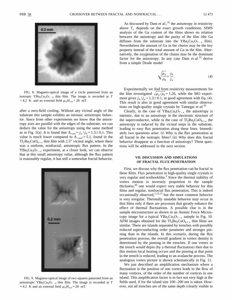
For comparison with the Tl2Ba2CuO61x thin films results,we now present MO experiments on YBa2Cu3O72x epitaxialthin films deposited on well-oriented NdGaO3 substrates.The film thickness is only 80 nm to prevent strain in tfilm.33,42 The YBa2Cu3O72x films are grown with thec axisperpendicular to the substrate and due to crystallograpanisotropy of the substrate surface, thea and b axes of theYBa2Cu3O72x film have the same orientation over the whosubstrate surface. This is verified using Rutherford bascattering and x-ray texture analysis.33 Due to the so-calledCu-O chains of YBa2Cu3O72x , which run along theb axis,the electronic structure is anisotropic, leading to, e.g., aniropy in the resistivity aboveTc .35,42 Anisotropy of j c canthus be expected. However, isotropic YBa2Cu3O72x films onNdGaO3 substrates have been also obtained.33 A magneto-optical image of a disk patterned from such a film is shoin Fig. 8. The image was taken in 28 mT applied field aftezero-field cooling to 4.2 K. The flux pattern in the samphas an isotropic, fractal character, resembling the resultthe 0° vicinal angle~well-oriented! Tl2Ba2CuO61x sample.We will discuss further results obtained on an YBa2Cu3O72xfilm with anisotropy in the resistivity aboveTc , patternedinto 2 squares with the edges parallel to the edges ofsubstrate. Figure 9 shows the MO image taken in 28
eaoc
th
eheveerio
Sion
r-ant
or
va-
of
te,di-
t
ues-
l inis
fleinedrinthee
os-
iblypin-uxy isin
intThe1.
e aofneew-
an
a
PRB 58 12 473CROSSOVER BETWEEN FRACTAL AND NONFRACTAL . . .
after a zero-field cooling. Without any vicinal angle of thsubstrate this sample exhibits an intrinsic anisotropic behior. Since from other experiments we know that the anisropy axes are parallel with the edges of the substrate, wededuce the value for the anisotropy using the same meas in Fig. 5~a!. It is found that Areal5 j a / j b51.360.1. Thisvalue is much lower compared to Areal55.1, found in theTl2Ba2CuO61x thin film with 2.5° vicinal angle, where therwas a uniform, nonfractal, anisotropic flux pattern. In tYBa2Cu3O72x experiment, at a closer look, we can obserthat at this small anisotropy value, although the flux pattis reasonably regular, it has still a somewhat fractal behav
FIG. 8. Magneto-optical image of a circle patterned fromisotropic YBa2Cu3O72d thin film. The image is recorded atT54.2 K and an external fieldm0Hext528 mT.
FIG. 9. Magneto-optical image of two squares patterned fromanisotropic YBa2Cu3O72d thin film. The image is recorded atT54.2 K and an external fieldm0Hext528 mT.
v-t-anod
nr.
As discussed by Damet al.,35 the anisotropy in resistivityabove Tc depends on the exact growth conditions. SIManalysis of the Ga content of the films shows no relatbetween the anisotropy and the purity of the film~the Gadiffuses from the substrate into the YBa2Cu3O72x film!.Nevertheless the amount of Ga in thechainsmay be the keyproperty instead of the total amount of Ga in the film. Altenatively, the oxygenation of the chains may be the dominfactor for the anisotropy. In any case Damet al.35 derivefrom a simple Drude model
Ara
rb5
j b
j a. ~4!
Experimentally we find from resistivity measurements fthe film investigatedAra /rb51.26, while the MO experi-ment givesj b / j a51.360.1, in good agreement with Eq.~4!.This result is also in good agreement with similar obsertions on high-quality single crystals by Tamegaiet al.43
Clearly, in the case of YBa2Cu3O72x the anisotropy isintrinsic, due to an anisotropy in the electronic structurethe superconductor, while in the case of Tl2Ba2CuO61x theanisotropy is induced by the vicinal steps in the substraleading to easy flux penetration along these lines. Immeately two questions arise:~i! Why is the flux penetration aall fractal in the isotropic films?~ii ! Why does this fractalbehavior disappear as a function of anisotropy? These qtions will be addressed in the next section.
VII. DISCUSSION AND SIMULATIONSOF FRACTAL FLUX PENETRATION
First, we discuss why the flux penetration can be fractathese films. Flux penetration in high-quality single crystalsvery regular and textbooklike.2 Since the thermal stability ovortex motion is inversely proportion to the sampthickness,44 one would expect very stable behavior for thfilms and regular, nonfractal flux penetration. This is indeoccasionally observed,1,12,13but the more common behaviois very irregular. Thermally unstable behavior may occurthin films only if there are processes that greatly enhanceeffect of thermal fluctuations. A possible clue is in thsample microstructure as shown in an Atomic Force Micrcopy image for a typical YBa2Cu3O72x sample in Fig. 10.AFM images obtained for the Tl2Ba2CuO61x thin films aresimilar. There are islands separated by trenches with possreduced superconducting order parameter and strongerning than in the islands. In this scenario, during the flpenetration process, the overall gradient in vortex densitdetermined by the pinning in the trenches. If one vortexthe trench would depin~by a thermal fluctuation! then due tothis motion local heating occurs and the pinning at that poin the trench is reduced, leading to an avalanche process.analogous vortex picture is shown schematically in Fig. 1
We just described an amplification mechanism wherfluctuation in the position of one vortex leads to the flowmany vortices, of the order of the number of vortices in oisland. This amplification factor is in fact not very high at thfields used, if for the island size 100–200 nm is taken. Hoever, not all trenches are of the same depth~clearly visible in
n
ely
n
atami-
dl0
eso
nroe
tail,el
Theing
s a
l
ble
on
ri-
forer-
n of
en-eto-nt,ctalrored in
12 474 PRB 58R. SURDEANUet al.
Fig. 10! and we believe that this idea is at least qualitativcorrect.
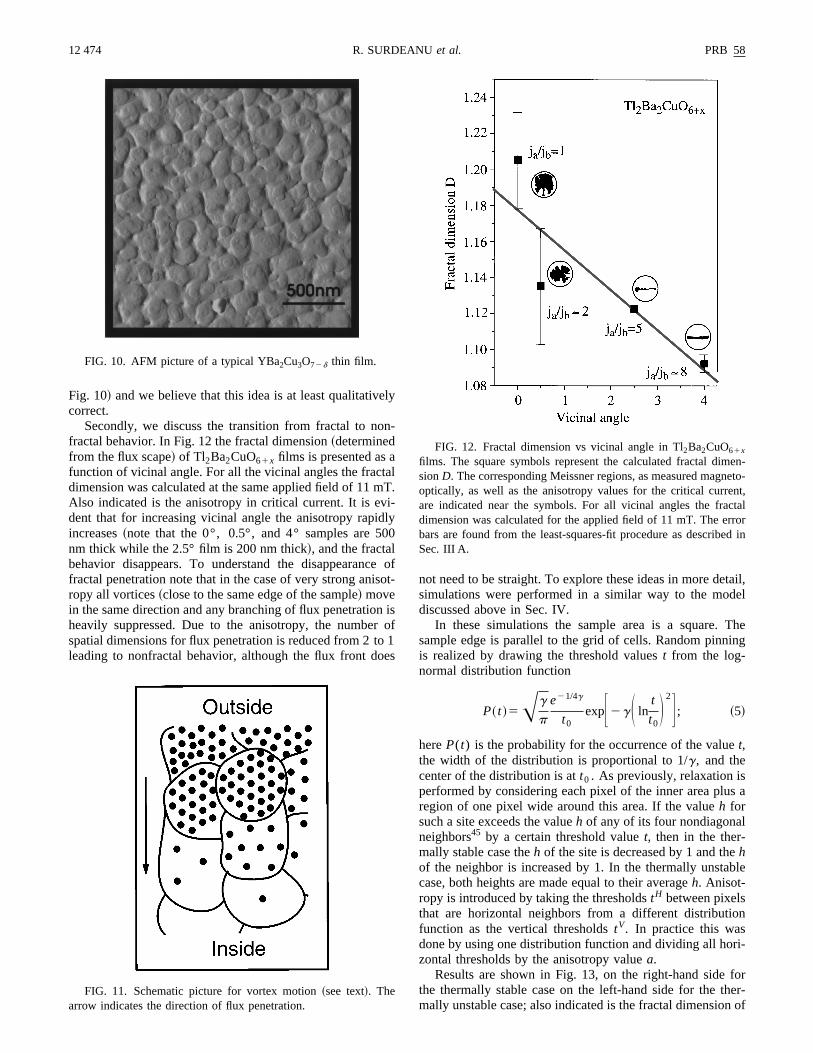
Secondly, we discuss the transition from fractal to nofractal behavior. In Fig. 12 the fractal dimension~determinedfrom the flux scape! of Tl2Ba2CuO61x films is presented asfunction of vicinal angle. For all the vicinal angles the fracdimension was calculated at the same applied field of 11Also indicated is the anisotropy in critical current. It is evdent that for increasing vicinal angle the anisotropy rapiincreases~note that the 0°, 0.5°, and 4° samples are 5nm thick while the 2.5° film is 200 nm thick!, and the fractalbehavior disappears. To understand the disappearancfractal penetration note that in the case of very strong aniropy all vortices~close to the same edge of the sample! movein the same direction and any branching of flux penetratioheavily suppressed. Due to the anisotropy, the numbespatial dimensions for flux penetration is reduced from 2 tleading to nonfractal behavior, although the flux front do
FIG. 10. AFM picture of a typical YBa2Cu3O72d thin film.
FIG. 11. Schematic picture for vortex motion~see text!. Thearrow indicates the direction of flux penetration.
-
lT.
y0
oft-
isof1s
not need to be straight. To explore these ideas in more desimulations were performed in a similar way to the moddiscussed above in Sec. IV.
In these simulations the sample area is a square.sample edge is parallel to the grid of cells. Random pinnis realized by drawing the threshold valuest from the log-normal distribution function
P~ t !5Ag
p
e21/4g
t0expF2gS ln
t
t0D 2G ; ~5!
hereP(t) is the probability for the occurrence of the valuet,the width of the distribution is proportional to 1/g, and thecenter of the distribution is att0 . As previously, relaxation isperformed by considering each pixel of the inner area pluregion of one pixel wide around this area. If the valueh forsuch a site exceeds the valueh of any of its four nondiagonaneighbors45 by a certain threshold valuet, then in the ther-mally stable case theh of the site is decreased by 1 and thehof the neighbor is increased by 1. In the thermally unstacase, both heights are made equal to their averageh. Anisot-ropy is introduced by taking the thresholdstH between pixelsthat are horizontal neighbors from a different distributifunction as the vertical thresholdstV. In practice this wasdone by using one distribution function and dividing all hozontal thresholds by the anisotropy valuea.
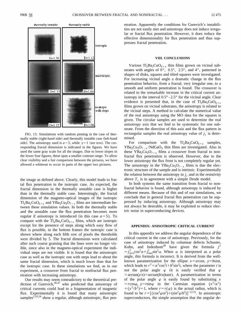
Results are shown in Fig. 13, on the right-hand sidethe thermally stable case on the left-hand side for the thmally unstable case; also indicated is the fractal dimensio
FIG. 12. Fractal dimension vs vicinal angle in Tl2Ba2CuO61x
films. The square symbols represent the calculated fractal dimsionD. The corresponding Meissner regions, as measured magnoptically, as well as the anisotropy values for the critical curreare indicated near the symbols. For all vicinal angles the fradimension was calculated for the applied field of 11 mT. The erbars are found from the least-squares-fit procedure as describSec. III A.
frthhectapi-bo
ldtevid
pit tfooun
reftiicn-
li-gu-
thep-
inated.uxa
r isan-ar
tolues isrealub-in
-thet.
lly
n-byweup-aylec-
f theheter,
r
de-
er
aveslloav
PRB 58 12 475CROSSOVER BETWEEN FRACTAL AND NONFRACTAL . . .
the image as defined above. Clearly, this model leads total flux penetration in the isotropic case. As expected,fractal dimension in the thermally unstable case is higthan in the thermally stable case. Interestingly, the fradimension of the magneto-optical images of the isotroTl2Ba2CuO61x and YBa2Cu3O72x films are intermediate between these simulation values. In both the thermally staand the unstable case the flux penetration becomes mregular if anisotropy is introduced~in this casea55). Tocompare with the Tl2Ba2CuO61x films, which are isotropicexcept for the presence of steps along which easy flowflux is possible, in the bottom frames the isotropic caseshown where along each fifth row of pixels the threshowere divided by 5. The fractal dimensions were calculaafter such coarse graining that the lines were no longerible, since also in the magneto-optical experiment the invidual steps are not visible. It is found that the anisotrocase as well as the isotropic one with steps lead to abousame fractal dimension, which is much lower than thatthe isotropic case. In these simulations we find, as inexperiment, a crossover from fractal to nonfractal flux peetration with increasing anisotropy.
Our results may seem contradictory to the theoretical pdiction of Gurevich,46,47 who predicted that anisotropy ocritical currents could lead to a fragmentation of magneflux. Experimentally it is found that many anisotropsamples2,10,24show a regular, although anisotropic, flux pe
FIG. 13. Simulations with random pinning in the case of thmally stable~right-hand side! and thermally instable case~left-handside!. The anisotropy used isa55, while g51 ~see text!. The cor-responding fractal dimension is indicated in the figures. We hused the same gray scale for all the images. Due to lower slopthe lower four figures, these span a smaller contrast range. To aclear visibility and a fair comparison between the pictures, we hallowed a whiteout to occur in parts of the upper two pictures.
acerl
c
lere
ofissds-i-cherr-
-
c
etration. Apparently the conditions for Gurevich’s instabities are not easily met and anisotropy does not induce irrelar or fractal flux penetration. However, it does reduceeffective dimensionality for flux penetration and thus supresses fractal penetration.
VIII. CONCLUSIONS
Various Tl2Ba2CuO61x thin films grown on vicinal sub-strates with angles of 0°, 0.5°, 2.5°, and 4°, patternedshapes of disks, squares and tilted squares were investigFor increasing vicinal angle a dramatic change in the flpenetration behavior, from a fractal, very irregular one, tosmooth and uniform penetration is found. The crossoverelated to the remarkable increase in the critical currentisotropy in the interval 0.5° –2.5° for the vicinal angle. Cleevidence is presented that, in the case of Tl2Ba2CuO61xfilms grown on vicinal substrates, the anisotropy is relatedthe vicinal steps. A method to calculate the numerical vaof the real anisotropy using the MO data for the squaregiven. The circular samples are used to determine theanisotropy axis that we find to be systematic for one sstrate. From the direction of this axis and the flux patternrectangular samples the real anisotropy value ofj c is deter-mined.
For comparison with the Tl2Ba2CuO61x samples,YBa2Cu3O72x /NdGaO3 thin films are investigated. Also inthese YBa2Cu3O72x films a crossover from fractal to nonfractal flux penetration is observed. However, due tolower anisotropy the flux front is not completely regular yeThe anisotropy in the YBa2Cu3O72x films is due the elec-tronic structure of the sample and is intrinsic. Experimentathe relation between the anisotropy inj c and in the resistivityaboveTc is in agreement with a simple Drude model.
In both systems the same transition from fractal to nofractal behavior is found, although anisotropy is induceddifferent means. Because of this and of our simulations,conclude that in general fractal flux penetration can be spressed by inducing anisotropy. Although anisotropy mnot always be desirable, it may be exploited to reduce etric noise in superconducting devices.
APPENDIX: ANISOTROPIC CRITICAL CURRENT
In this appendix we address the angular dependence ocritical current in the case of anisotropy. Previously, for tcase of anisotropy induced by columnar defects SchusKuhn, and Indenbom38 have given the formula j 2
5 j min2 cos2a1jmax
2 sin2a. When a is interpreted as a polaangle, this formula isincorrect. It is derived from the well-known parametrization for the ellipsex5acost, y5bsint,which leads tor 25a2cos2t1b2sin2t, where the parametert isnot the polar angle w ~it is easily verified that w5arctan(y/x)5arctan(b/a)tant). A parametrization in termsof the polar anglew is easily found by substitutingx5rcosw, y5rsinw in the Cartesian equation (x2/a2)1(y2/b2)51, wherer 5r (w) is the actual radius, which isfound to ber 5@(cos2w/a2)1(sin2w/b2)#2(1/2). In anisotropicsuperconductors, the simple assumption that the angular
-
einwe
-:
ahe
ng
oor
gy
12 476 PRB 58R. SURDEANUet al.
pendence of the pinning force per length,f p , is given by anellipse, combined with a critical current density given byj c5 f p /F0 whereF0 is the flux quantum, leads to the following equation for the critical current as a function of angle
j ~w!51
Acos2w
j a2
1sin2w
j b2
. ~A1!
Finally we note that although the equation for the criticcurrent as a function of angle in Ref. 38 is incorrect, t
b-
no
.
-
M.
n-ko
ok
d
s
M.
A.-
C
-A
l
formula for the anisotropy@Eq. ~1!# in the same paper iscorrect.
ACKNOWLEDGMENTS
This work is part of the research program of the Stichtivoor Fundamenteel Onderzoek der Materie~FOM!, which isfinancially supported by the Nederlandse Organisatie vWetenschappelijk Onderzoek~NWO!. The work performedat the State University of New York at Buffalo~SUNY atBuffalo! was sponsored in part by New York State EnerResearch and Development Authority~NYSERDA! and OakRidge National Laboratory~ORNL!.
ys.
-U.on-
, R.
n,
.an,
H.
, B.
Z.
H.
R.
B.
r, F.sen,
ries-
p,
1Th. Schuster, H. Kuhn, E.H. Brandt, M.V. Indenbom, M.R. Kolischka, and M. Konczykowski, Phys. Rev. B50, 16 684~1994!.
2M.R. Koblischka and R.J. Wijngaarden, Semicond. Sci. Tech8, 199 ~1995!.
3M.V. Indenbom, Th. Schuster, M.R. Koblischka, A. Forkl, HKronmuller, L.A. Dorosinskii, V.K. Vlasko-Vlasov, A.A. Poly-anskii, R.L. Prozorov, and V.I. Nikitenko, Physica C209, 259~1993!.
4P. Brull, D. Kirchgassner, and P. Leiderer, Physica C182, 339~1991!.
5A. Forkl, H.U. Habermeier, B. Leibold, T. Dragon, and H. Kronmuller, Physica C180, 155 ~1991!.
6H.U. Habermeier and R. Zaiss, Cryogenics20, 535 ~1980!.7M.R. Koblischka, Supercond. Sci. Technol.9, 271 ~1996!.8Th. Schuster, M.R. Koblischka, H. Kuhn, B. Ludescher,
Leghissa, M. Lippert, and H. Kronmu¨ller, Physica C196, 373~1992!.
9Th. Schuster, H. Kuhn, M.R. Koblischka, H. Theuss, H. Kromuller, M. Leghissa, M. Kraus, and G. Saemann-IschenPhys. Rev. B47, 373 ~1993!.
10R.J. Wijngaarden, R. Griessen, J. Fendrich, and W.K. KwPhys. Rev. B55, 3268~1997!.
11M.V. Indenbom, A. Forkl, B. Ludescher, H. Kronmu¨ller, H.U.Habermeier, B. Leibold, G. D’Anna, T.W. Li, P.H. Kes, anA.A. Menovsky, Physica C226, 325 ~1994!.
12Th. Schuster, H. Kuhn, M.V. Indenbom, M. Leghissa, M. Krauand M. Konczykowski, Phys. Rev. B51, 16 358~1995!.
13Th. Schuster, M.V. Indenbom, H. Kuhn, E.H. Brandt, andKonczykowski, Phys. Rev. Lett.73, 1424~1994!.
14R. Potratz, W. Klein, H.U. Habermeier, and H. Kronmu¨ller, Phys.Status Solidi A60, 417 ~1980!.
15W. Klein and H. Kronmu¨ller, Phys. Status Solidi A67, 109~1987!.
16M.V. Indenbom, Th. Schuster, H. Kuhn, H. Kronmu¨ller, T.W. Li,and A.A. Menovsky, Phys. Rev. B51, 15 484~1995!.
17M. Turchinskaya, D.L. Kaiser, F.W. Gayle, A.J. Shapiro,Roytburd, V.K. Vlasko-Vlasov, A.A. Polyanskii, and V.I. Nikitenko, Physica C216, 205 ~1993!.
18L.A. Dorosinskii, M.V. Indenbom, V.I. Nikitenko, Yu.A.Ossip’yan, A.A. Polyanskii, and V.K. Vlasko-Vlasov, Physica203, 149 ~1992!.
19M. Baziljevich, Appl. Phys. Lett.69, 3590~1996!.20M. Baziljevich, A.V. Bobyl, H. Bratsberg, R. Deltour, M.E. Gae
vski, Yu.M. Galperin, V. Gasumyants, T.H. Johansen, I.
l.
,
,
,
.
Khrebtov, V.N. Leonov, D.V. Shantsev, and R.A. Suris, J. PhIV 6, C3-259~1996!.
21B.B. Mandelbrot, Science155, 636 ~1967!.22B.B. Mandelbrot,The Fractal Geometry of Nature~Freeman,
New York, 1984!.23A.-L. Barabasi and H.E. Stanley,Fractal Concepts In Surface
Growth ~Cambridge University Press, New York, 1995!.24T. Haage, J.Q. Li, B. Leibold, M. Cardona, J. Zegenhagen, H.
Habermeier, A. Forkl, Ch. Jooss, R. Warthmann, and H. Krmuller, Solid State Commun.99, 553 ~1996!; T. Haage, J. Ze-genhagen, J.Q. Li, H.-U. Habermeier, M. Cardona, Ch. JoossWarthmann, A. Forkl, and H. Kronmu¨ller, Phys. Rev. B56,8404 ~1997!.
25C.A. Wang, Z.F. Ren, J.H. Wang, D.K. Petrov, M.J. NaughtoW.Y. Yu, and A. Petrou, Physica C262, 98 ~1996!.
26C.C Tsuei, J.R. Kirtley, M. Rupp, J.Z. Sun, A. Gupta, M.BKetchen, C.A. Wang, Z.F. Ren, J.H. Wang, and M. BhushScience271, 329 ~1996!.
27C. Rossel, M. Willemin, J. Hofer, H. Keller, Z.F. Ren, and J.Wang, Physica C287, 136 ~1997!.
28J.D. Jorgensen, O. Chmaissem, J.L. Wagner, W.R. JensenDabrowski, D.G. Hinks, and J.F. Mitchell, Physica C282-287,97 ~1997!.
29Z.F. Ren, J.H. Wang, and D.J. Miller, Appl. Phys. Lett.69, 1798~1996!.
30Z.F. Ren, J.H. Wang, and D.J. Miller, Appl. Phys. Lett.71, 1706~1997!.
31C.C. Tsuei, J.R. Kirtley, Z.F. Ren, J.H. Wang, H. Raffy, and Z.Li, Nature ~London! 387, 481 ~1997!.
32Willemin, C. Rossel, J. Hofer, H. Keller, Z. F. Ren, and J.Wang, Phys. Rev. B57, 6137~1998!.
33B. Dam, J. Rector, M.F. Chang, S. Kars, D.G. de Groot, andGriessen, Appl. Phys. Lett.65, 1581~1994!.
34J.H. Rector, P. Koster, F. Peerdeman, D.G. de Groot, andDam, J. Alloys Compd.251, 114 ~1997!.
35B. Dam, J. Rector, R. Surdeanu, R.J. Wijngaarden, P. KostePeerdeman, J. van Berkum, D.G. de Groot, and R. GriesPhysica C282-287, 665 ~1997!.
36R.J. Wijngaarden, H.J.W. Spoelder, R. Surdeanu, and R. Gsen, Phys. Rev. B54, 6742~1996!.
37C.A. Duran, P.L. Gammel, R. Wolfe, V.J. Fratello, D.J. BishoJ.P. Rice, and D.M. Ginsberg, Nature~London! 357, 474~1992!.
38Th. Schuster, H. Kuhn, and M.V. Indenbom, Phys. Rev. B52, 15621 ~1995!.
39Th. Schuster, M.V. Indenbom, H. Kuhn, H. Kronmu¨ller, M.

tz
ial
,
r ofticesre-
PRB 58 12 477CROSSOVER BETWEEN FRACTAL AND NONFRACTAL . . .
Leghissa, and G. Kreiselmeyer, Phys. Rev. B50, 9499~1994!.40A.M. Campbell and J.E. Evetts, Adv. Phys.21, 199 ~1972!.41E.H. Brandt, Phys. Rev. B46, 8628~1992!.42T. Scherer, P. Marienhoff, R. Herwig, M. Neuhaus, and W. Ju
Physica C197, 79 ~1992!.43T. Tamegai, R. Yamada, T. Yasuhira, and T. Shibauchi,
Proceedings of the 8th International Workshop on CriticCurrents in Superconductrs~IWCC!, Kitakyushu, 1996, editedby T. Matsushita and K. Yamafuji~World Scientific, Singapore
i,
n
1996!, p. 125.44M. Tinkham, Introduction to Superconductivity, 2nd ed.
~McGraw-Hill, Inc., 1996!, Sec. 5.7.2.45We found that to be able to generate fractal patterns only fou
the closest neighbors must be considered. Otherwise the vorwill move around high thresholds and no fractal behaviorsults.
46A. Gurevich, Phys. Rev. Lett.65, 3197~1990!.47A. Gurevich, Phys. Rev. B46, 3638~1992!.