Embed Size (px)
Citation preview

CRUISE REPORTRRS James Cook cruise JC21
6th January – 10th February 2008
Rodman, Panama — Puerto Caldera, Costa Rica
“Accretion of the lower oceanic crust atfast-spreading ridges: a rock drill and near-bottom seafloor survey in support of IODP
drilling in Hess Deep”
C.J. MacLeod (Chief Scientist)D.A.H. Teagle, K.M. Gillis
P.W. Cazenave, H.E. Hansen, M. Harris, K.A. Howard, S.D. Hurst,B. Ildefonse, C.J. Lissenberg, A. Morris, D.J. Shillington & M. Tominaga
Isis Team: D.R. Turner, J.A. Cooper, S.E. Dodd, D. Edge, W.H. Handley, P.J. Mason, L.Rolley, A.M. SherringBGS Team: D.J. Smith, D. Baxter, N.C. Campbell, M.D. Wilson
School of Earth & Ocean Sciences,Cardiff University,Main Building, Park Place,Cardiff CF10 3YE,Wales, United Kingdom

CRUISE REPORTRRS James Cook cruise JC21
6th January – 10th February 2008Rodman, Panama — Puerto Caldera, Costa Rica
ContentsCruise SummaryList of ParticipantsContact Details
1. Introduction1.1 Preamble ………… 11.2 Cruise objectives ………… 21.3 Scientific background ………… 21.4 Geology of Hess Deep: previous work ………… 31.5 Original survey plan ………… 5
2. Ship’s Systems2.1 Description of ship-fitted systems ………… 82.2 Potential field measurements: operations …………122.3 EM120 (ship’s) swath bathymetry: operations and processing summary …………13
3. Isis Remotely-Operated Vehicle3.1 The Isis vehicle ………… 153.2 Isis operational strategy ………… 173.3 Isis swath acquisition and processing ………… 183.4 Use of a deep-towed magnetometer on Isis ………… 223.5 Isis near-bottom operations ………… 22
4. BRIDGE Seabed Rock Drill ………… 26
5. Sample Descriptions5.1 Introduction ………… 275.2 Igneous petrology ………… 275.3 Structural petrology ………… 305.4 Metamorphic petrology ………… 31
6. Daily Narrative ………… 32
7. End Matter7.1 References ………… 487.2 Acknowledgements ………… 497.3 A note on the citation of this report ………… 497.4 List of Appendices ………… 49

Cruise SummaryRRS James Cook Cruise JC21 (6th January–10th February 2008) investigated exposures oflower oceanic crust that crop out at Hess Deep (~2°15’N, 101°30’W); a rifted depressionformed by the westward propagation of the Cocos-Nazca plate boundary towards the EastPacific Rise. Hess Deep provides unique exposures of the deeper levels of ocean crustformed at a fast spreading mid-ocean ridge, one of the fundamental processes in the solidEarth cycle. Our principal aims were to provide detailed site survey for future IntegratedOcean Drilling Program (IODP) drilling, and to collect a suite of deep crustal rocks withgood geological context to test hypotheses of mid-ocean ridge accretion.Our approach was: (i) to collect improved regional bathymetric (EM120), gravity andmagnetic data using ship-mounted acquisition systems, then (ii) undertake detailed metre-scale bathymetry and near-bottom survey and sampling using the Isis remotely-operatedvehicle (ROV), complemented by (ii) the drilling of shallow (~1m), geographicallyorientated cores using the ‘BRIDGE’ seabed rock drill. Twelve dives (Isis 67 to 78) wereundertaken over an aggregate period of 14.5 days in depths from 3000 to 5400m, withdifferent vehicle configurations for swath mapping and sample collection. Dives weretypically ~36 hours duration, up to a maximum of 45 hours. Four dives (67, 68, 71, 74)collected high-resolution bathymetry using the Isis-mounted SM2000 multibeamechosounder. Driven at an altitude of 100m, with overlapping lines spaced between 150 to200m, we obtained metre-scale bathymetry of 11km2 from two areas: the slope north of thenadir of Hess Deep (~2°15’N 101°33’W; 5400 to 4400m), and the ‘intra-rift ridge’ horstblock just farther north within the rift valley (~2°17.5’N101°32’W; 4200 to 3000m). Detailedmaps generated onboard by the science party were then used to guide near-bottomgeological mapping and sampling. Coupled with the surface data, these data provide newinsights into the rifting history of Hess Deep. For eight dives Isis ROV was deployed nearbottom to acquire digital imagery of basement exposures and to collect outcrop samplesusing the vehicle’s manipulator arms. 145 samples totalling 760kg were collected, with thelargest single dive haul being 157kg. Rock types range from harzburgite, dunite, troctolite,olivine gabbro and other gabbro lithologies, to dolerites and basalts. Our detailedmapping indicates a more complex distribution of rock types across Hess Deep thansuggested by previous investigations, and requires significant refinement of presentlyaccepted models for the structure and tectonic evolution of the rift. Importantly however,the ocean crustal stratigraphy at Hess Deep can still be re-constructed enabling primaryscience questions regading fast-spread lower crustal accretion mechanisms to beaddressed in post-cruise study of the samples collected. The proposed IODP drilling(Proposal 551-Full5, Gillis et al.) will be enhanced and strengthened by our new findingswith more confidently established geological context of potential drill sites.The sampling of geographically oriented cores using the BRIDGE drill, required fordetermination of magmatic flow trajectories, proved challenging. This was principally dueto the small size of (<10 m2) outcrops, the rugged terrain and the great depth of operations(4800 to 5100m). Acoustic navigation of the drill using the ultra-short baseline (USBL)system was intermittent and imprecise at these depths, and high equatorial pelagicsedimentation rates commonly resulted in turbid near-bottom conditions that madeprecise positioning of the rig and site location difficult. Science operations at Hess Deepwere interrupted to make a compassionate evacuation of a crew member in Costa Rica(24th to 31st January, 2008) reducing by more than a third the time available for scienceoperations. This resulted in only one day being devoted to drilling, and only threeBRIDGE drill deployments. These did not succeed in recovering orientated core. Becauseof the reduced science time available the second phase of science operations insteadconcentrated on the known rewards of ROV sampling. In consequence we did not havethe opportunity to attempt to solve the difficulties of navigating the BRIDGE drill ontosmall outcrops in very deep water.

List of Participants
Science party (academic)
Dr Christopher J. MacLeod Principal Investigator/geologist watch-leader 8-12Prof. Damon A.H. Teagle Co-Investigator/geologist watch-leader 12-4Prof Kathryn M. Gillis Project Partner/geologist watch-leader 4-8Dr Benoît Ildefonse Project Partner/geologist 8-12 watchDr Antony Morris Recognised Researcher/geologist/geophysicist 8-12 watchDr Donna J. Shillington Geophysicist/GMT team leader 8-12 watchDr. Stephen D. Hurst Geophysicist/GMTer 12-4 watchHeidi E. Hansen Geologist 12-4 watchMichelle Harris Geologist 12-4 watchDr C. Johan Lissenberg Geologist 4-8 watchKerry Howard Geologist 4-8 watchPierre W. Cazenave Computer Geek/GMTer 4-8 watchMasako Tominaga Geophysicist/GMTer 4-8 watch
Science party (technical)
David R. Turner Isis team leader, National Marine FacilityJames A. Cooper Isis team, National Marine FacilitySimon E. Dodd Isis team, National Marine FacilityDavid Edge Isis team, National Marine FacilityWilliam H. Handley Isis team, National Marine FacilityPeter J. Mason Isis team, National Marine FacilityLeighton Rolley Computing technician/Isis team, National Marine FacilityAlan M. Sherring Isis team, National Marine FacilityDavid J. Smith BRIDGE drill team leader, British Geological SurveyDavid Baxter BGS team, British Geological SurveyNeil C. Campbell BGS team, British Geological SurveyMichael D. Wilson BGS team, British Geological Survey
Ship’s crew
Antonio Gatti MasterPeter Reynolds Chief Officer Titus Owoso 2nd OfficerDarcy White 3rd Officer Phil Harwood PurserBernie McDonald Chief Engineer Glynn Collard 2nd EngineerChris Uttley 3rd Engineer Bob Masters ETOEamonn Ilett Sea Systems Manager Viv Wythe Deck EngineerKevin Luckhurst CPO Deck Mark Squibb CPO ScientificStuart Cook PO Deck Emlyn Williams ERPOSteven Duncan Seaman Martin McGeown SeamanStephen Setters Seaman Colin Birtwhistle SeamanMark Preston Head Chef Walter Link ChefJacqueline Paterson* Stewardess Amy Whalen* Catering AssistantGraham Mingay# Steward
(*left ship, #joined ship – Puerto Caldera 27th January 2008)

Academic science party contact details
Dr Christopher J. MacLeod School of Earth & Ocean Sciences,Cardiff University,Main Building, Park Place,Cardiff CF10 3YE, Wales, UKTel: +44-(0)29-2087-4332Fax: +44-(0)29-2087-4326E-mail: [email protected]
Pierre Roger Cazenave School of Ocean and Earth Science,National Oceanography Centre,University of Southampton,European Way, Southampton, SO14-3ZH, UKSouthampton, SO14-3ZH, UKTel: +44-(0)23-8059-3666Fax: +44-(0)23-8059-3052E-mail: [email protected]
Prof Kathryn M. Gillis School of Earth and Ocean Sciences,University of Victoria,P.O. Box 3500, Victoria, BC, CanadaTel: +1-250-472-4345Fax: +1-250-6200E-mail: [email protected]
Heidi E. Hansen Department of Earth Sciences,University of Bergen,Allégt 41, N-5007 Bergen, NorwayTel: +47-90-87-04-50Fax: +47-55-58-36-60E-mail: [email protected]
Michelle Harris School of Ocean and Earth Science,National Oceanography Centre,University of Southampton,European Way, Southampton, SO14-3ZH, UKTel: +44-(0)23-8059-6133Fax: +44-(0)23-8059-3052E-mail: [email protected]
Kerry Howard School of Earth & Ocean Sciences,Cardiff University,Main Building, Park Place,Cardiff CF10 3YE, Wales, UKTel: +44-(0)29-2087-4830Fax: +44-(0)29-2087-4326E-mail: [email protected]

Dr. Stephen D. Hurst 1301 W. Green St., 245 NHBUrbana, IL 61801 USATel: +1-217-333-0205Fax: +1-217-244-4996E-mail: [email protected]
Dr Benoît Ildefonse Géosciences Montpellier, CNRSUniversité Montpellier 234095 Montpellier cedex 05, FranceTel: +33-(0)4-67-14-38-18Fax: +33-(0)4-67-14-36-03E-mail: [email protected]
Dr C. Johan Lissenberg School of Earth & Ocean Sciences,Cardiff University,Main Building, Park Place,Cardiff CF10 3YE, Wales, UKTel: +44-(0)29-2087-4830Fax: +44-(0)29-2087-4326E-mail: [email protected]: [email protected]
Dr Antony Morris School of Earth, Ocean and Environmental Sciences,University of Plymouth,Drake Circus, Plymouth PL4 8AA, UKTel: +44 1752 233120Fax: +44 1752 233117E-mail: [email protected]
Dr Donna J. Shillington Lamont Doherty Earth Observatory,Columbia University,61 Route 9W, Palisades, NY 10964, USATel: +1 845-365-8818E-mail: [email protected]
Prof. Damon A.H. Teagle School of Ocean and Earth Science,National Oceanography Centre,University of Southampton,European Way, Southampton, SO14-3ZH, UKTel: +44-(0)23-8059-2723Fax: +44-(0)23-8059-3052E-mail: [email protected]
Masako Tominaga Department of Oceanography,Texas A&M University,3146 TAMU College Station, TX 77843-3146, USATel: +1-979-204-2854Fax:+1-979-845-6331E-mail: [email protected]

RRS James Cook cruise JC21 cruise report 1 Chapter 1
Chapter 1. Introduction1.1 PreambleRoyal Research Ship (RRS) James Cook cruise JC21 was funded by the UK’s NaturalEnvironment Research Council (NERC) via its programme of support for the IntegratedOcean Drilling Program (IODP). The UKIODP Site Survey Initiative (SSI) is a means tofund cruises that provide essential site survey information in support of IODP drillingproposals of high scientific interest and/or strategic value to the UK scientific community.One such proposal was ODP/IODP Proposal #551, by Gillis et al., which seeks toinvestigate the processes of accretion of the lower crust at fast-spreading mid-oceanridges. This experiment proposed to drill a series of moderate depth holes (~300m) in the‘tectonic window’ of lower crustal rocks known to be exposed in Hess Deep (2°N, 101°W),a rift valley lying at the intersection of the Pacific, Cocos and Nazca plates in the easternPacific Ocean. In part this proposal built upon the results of previous Ocean DrillingProgram (ODP) operations there in 1992-93 (Leg 147). Kathy Gillis was a co-chief of thisexpedition and Chris MacLeod one of the scientific party. Although the follow-upODP/IODP Proposal #551 included no British authors, its scientific themes and objectivesare tightly aligned to the research interests of many UK scientists and institutions,including Chris MacLeod (Cardiff) and Damon Teagle (Southampton).Proposal #551 was first submitted to the ODP in 1999. It was reviewed by the JOIDESScience Steering and Evaluation Panel, sent for external review, and then passed (withstrong endorsement) to the Science Committee for potential scheduling. However, the SiteSurvey Panel (SSP) concluded that the available site survey data for Hess Deep was notsufficient for it to be considered for scheduling by the Science Committee. The proposalwas therefore put aside until more detailed characterisation of the proposed drill sites wasavailable. Thus it currently (in early 2008) remains, though now lodged with the successorto the ODP Science Committee, the IODP Science Planning Committee (SPC). If site surveyinformation can be supplied, via the SSP, to the SPC, Proposal #551 may once again beconsidered for scientific ranking and potential scheduling at the SPC’s March 2008(and/or subsequent) meeting(s).Efforts were made by the proponents of Proposal #551 to obtain site survey funding in theUS and in Japan, but to date these have been unsuccessful. In 2003 Kathy Gillis agreed to asuggestion by Chris MacLeod that he attempt to obtain funding through the newly-announced UKIODP SSI. Following a pre-proposal in January 2004, full grant proposalNE/C509023/1 was submitted to the UKIODP SSI in April 2004. It was led by ChrisMacLeod as Principal Investigator (PI) and Damon Teagle as Co-Investigator (Co-I), andincluded Kathy Gillis as a Project Partner. The other project partners were Benoît Ildefonseand Rolf Pedersen, both proponents of ODP/IODP Proposal #551, and Tony Morris wasnamed as a Recognised Researcher.Grant proposal NE/C509023/1 was approved for funding in mid-2004, and the wheelsput in motion that were eventually to lead to the scheduling of cruise JC21 some three-and-a-half years later. One of the attractions to the reviewers of the grant application isthat it proposed not only the acquisition of the requisite site survey data for ODP/IODPProposal #551 but – with the plan to use the Isis remotely-operated vehicle (ROV) andBritish Geological Survey (BGS)’s ‘BRIDGE’ seabed rock drill to obtain large numbers oforientated samples from the Hess Deep lower crustal section – included an invaluablescientific programme in its own right.

RRS James Cook cruise JC21 cruise report 2 Chapter 1
1.2 Cruise objectivesThe specific objectives of proposal NE/C509023/1 were as follows:“(1) To find suitable locations for the drill sites proposed in the highly-ranked IODPproposal #551. This requires use of a remotely-operated vehicle or autonomousunderwater vehicle to collect accurately navigated high-resolution bathymetry andseafloor photographs in order to identify areas of outcrop and/or flat benches suitable forspud-in by a non-riser drillship.(2) To characterise the lithologies present at these potential sites, and provide geologicalcontext on a broader scale, by surveying and sampling in as much detail as possible thelower crustal section exposed on the southern slope of the intra-rift ridge of Hess Deep.This we intend to do by using the British Geological Survey’s ‘BRIDGE’ seabed rock drillto collect geographically orientated core material, supplemented if appropriate withsampling using an ROV and/or dredging.”The broader scientific objectives were defined as follows:“(3) To quantify as far as possible the heat and mass flux between mantle and crust andcrust and ocean by constraining the structure, composition and alteration history ofgabbroic rocks from the Hess Deep section.(4) To test the hypothesis that the Oman ophiolite is an appropriate analogue for fast-spread ocean lithosphere.(5) To test competing models for the accretion of the lower ocean crust at fast-spreadingridges.”
1.3 Scientific backgroundA fundamental question in geodynamics is the nature of magmatic processes belowoceanic ridges and, in particular, how the lower oceanic crust forms. Early, simple viewsinvolving single, large fractionating magma chambers inwhich the lower crustal gabbros accreted by side-wallcrystallisation and crystal settling have now been largelyabandoned. Seismic evidence from fast-spreading systemshas identified a more restricted, perched magma lens at thetop of the gabbro section which extends along the ridge,underlain by a broader zone of low seismic velocity that isinferred to represent a crystal mush containing a small butpoorly constrained proportion of melt [e.g. Sinton & Detrick,1992]. Slow-spreading axes ordinarily lack persistent magmabodies and the lower crust appears to freeze solid or nearlysolid between melt delivery episodes from the mantle.These geophysical results have led to re-evaluation of themechanism of accretion of lower crustal gabbros. Fieldevidence from the Oman ophiolite has been used to supportthe so-called ‘gabbro glacier’ hypothesis (Fig. 1.1) in whichthe gabbro section is built up by crystallisation along thefloor and walls of the perched magma lens, followed bydownwards ductile flow towards the Moho and away fromthe ridge [Henstock et al., 1993; Phipps Morgan & Chen,1993; Quick & Denlinger, 1993]. This is opposed by afundamentally different hypothesis, based upon the samefield relationships in Oman, in which modally layered
Figure 1.1: (A) ‘Gabbro glacier’ vs(B) ‘sheeted sill’ models for accretionof the lower crust at fast-spreadingridges. Dashed arrows depict thedirection of melt flow; solid arrowsthe flow direction of crystals. Sillswhich are melt-filled are shown inblack, part-crystallised in grey, fullycrystallised in white.

RRS James Cook cruise JC21 cruise report 3 Chapter 1
gabbros that form the lower part of the crust and Moho transition zone are suggested toform in situ in a series of ‘sheeted sills’, without any significant vertical transport [Boudieret al., 1996; Kelemen et al., 1997; MacLeod & Yaouancq, 2000] (Fig. 1.1). Magma ponded insuch sills may crystallise 10-50% of their mass as cumulates (and develop compositionalgrading), with the remaining melt continuing upwards to form more evolved uppergabbros, dykes and lavas.These models are all based upon the assumption that theinternal structure of the Oman ophiolite is a directanalogue for modern fast-spread ocean lithosphere. Thelower crust of the EPR should therefore be formed fromgabbros that share the characteristic internal structure ofthe plutonic section in Oman: viz. a series of sub-horizontal layered gabbros overlain by more massivegabbros with steep, ridge-parallel magmatic foliationsand lineations; and thence a thin layer of varitexturedgabbros of heterogeneous texture and composition (Fig.1.2). However, this is yet to be properly tested. Because ofthe inferred continuity of magmatic accretion at fast-spreading mid-ocean ridges the deeper levels of the crustare not normally exposed on the seafloor. This is markedcontrast to slow-spreading ridges, where tectonicstretching is significant, and lower crust and mantle rocksare exhumed in many areas.Ocean drilling of intact fast-spread crust has so farpenetrated only metres into plutonic rock, at ODP Hole1256D [Wilson et al., 2006]. Until such time as we areprepared to commit the considerable resources needed todeepen this hole or drill another as far as the Moho, direct information as to the nature ofprocesses beneath fast-spreading ridges, and testing of the Oman ophiolite analogy, islimited to exploring the very few ‘tectonic windows’ of fast-spread lower crust that areknown to exist. Sections have been discovered at the margins of the three microplates thatoccur along the EPR: the Galapagos, Easter and Juan Fernandez microplates, found at 2°N,23°S and 33°S respectively. The best known and most extensive of these is at Hess Deep, atthe northern edge of the Galapagos microplate, and which has been the subject of previoussubmersible and ODP operations, detailed below. In many respects the gabbros drilled inHess Deep do bear a close similarity to the foliated gabbros in Oman, and a markeddissimilarity to slow-spread gabbros [MacLeod et al., 1996a], but this is based upon verylimited evidence, and the analogy needs to be explored far more rigorously.
1.4 Geology of Hess Deep: previous workBy far the most substantial and most accessible of theknown tectonic windows of fast-spread lower crust isexposed in the Hess Deep rift valley (2°N, 101°W),near the Galapagos microplate at the Pacific-Cocos-Nazca triple junction (Fig. 1.3). The Cocos-Nazcaspreading centre is propagating westward at a ratecomparable to the half spreading rate of the EPR (~65mm/yr); hence young (~1Ma) lithosphere generatedat the EPR is being rifted ahead of the advancingCocos-Nazca spreading ridge [Lonsdale, 1988].Although this ridge-ridge-ridge triple junction is Figure 1.3. Location of Hess Deep at the
Pacific-Cocos-Nazca triple junction
Figure 1.2. Internal structure of the Omanophiolite [e.g. Nicolas et al., 2000].

RRS James Cook cruise JC21 cruise report 4 Chapter 1
therefore stable on a regional scale, in detail the Galapagos microplate immediately southof Hess Deep appears to be rotating clockwise, and another tiny microplate to the northrotating anticlockwise, as the Cocos-Nazca rift propagates westward [Klein et al., 2005].The EPR lithosphere that is entering Hess Deep has itself almost certainly been affected byearlier on-axis tectonics associated with long-lived duelling propagating rifts on the N-SEPR axis.The principal topographic features ofthe Hess Deep rift valley are the HessDeep nadir itself at 5400mbsl, the tip ofthe slow-spreading Cocos-Nazca ridgeat 4000-4500mbsl, the intra-rift ridgethat rises to 3000mbsl north of HessDeep, and the steep bounding scarpsnorth of the intra-rift ridge and southof the Hess Deep nadir (Fig. 1.4).Submersible studies [Francheteau etal., 1990] have shown that plutonicrocks are exposed on an intra-rift ridgeand on the slope southward from it down to the axis of the Deep at ~5400 m water depth(Fig. 1.5). Minor outcrops of the uppermost gabbros are also exposed along the north wallof Hess Deep beneath extensive sheeted dyke and lava sections [Karson et al. 2002]. ODPoperations during Leg 147 drilled a 150m-deep hole into gabbros on the western summitof the intra-rift ridge (Site 894) and two ~100m holes into harzburgites and dunites fromthe shallow mantle and inferred crust-mantle transition zone at the foot of the eastern endof the intra-rift ridge at Site 895 (Figs. 1.4 and 1.5; Gillis et al., 1993).
The tectonic disruption of theHess Deep rift valley is complexand is not completelyunderstood. Two models forextension and the emplacementof the intra-rift ridge wereproposed by Francheteau et al.[1990]. One model invokesdiapiric uplift of serpentinizedmantle along high angle, normalfaults. The other model calls fordetachment faulting and blockrotation on listric normal faultsand diapiric uplift of the intra-riftridge (Fig. 1.6). Structural andpaleomagnetic data for Site 894indicate that the intra-rift ridgerepresents a large, intact crustalblock that has been rotated alongboth horizontal and vertical axes[MacLeod et al., 1996b]. MacLeodet al conclude that emplacement
of the intra-rift ridge was accomplished by a combination of low-angle detachment andhigh-angle normal faulting (Fig. 1.7).Geophysical surveys at Hess Deep provide support for the detachment model. On-bottomseismic data indicate low velocities (2-3 km/s) in the vicinity of Hess Deep with highervelocities beneath the intra-rift ridge (3.0-5 km/s) [Wiggins et al., 1996]. At Site 894, the
Figure 1.4. Tectonic elements of the Hess Deep rift valley
Figure 1.5. Location ofNautile submersible dives and summary oflithologies recovered (Francheteau et al. [1990)] plus ODP Leg 147 drillsites (from Gillis et al. [1993])

RRS James Cook cruise JC21 cruise report 5 Chapter 1
lowest seismic velocities occur within the upper 600 m where fractured gabbros crop out.Higher velocities with depth are interpreted as peridotite. Sea surface and seafloor gravitydata indicate the presence of low density material beneath Hess Deep and high densitymaterial beneath the intra-rift ridge [Ballu et al., 1999].
1.5 Original survey planPrior to cruise JC21 the only geological information available to select drill sites forproposal #551 had come from two submersible dives by Francheteau et al. [1990].Although these dives provide crucial reconnaissance on the distribution of outcrop androck types there was limited coverage of the area of interest, and locations were sitedusing 1980s technology. The IODP Site Survey Panel therefore requested detailed,accurately navigated bathymetry and seafloor imagery to distinguish outcrop from talus,and find benches and other flatter regions into which non-riser IODP drill holes could be
Figure 1.6. Two alternative models for the structure of Hess Deep, as proposed by Francheteau et al. [1990]
Figure 1.7. Cross section thtrough the northern part of Hess Deep as proposed by MacLeod et al. [1996b] on the basis ofdrilling results from ODP Leg 147.
RRS James Cook cruise JC21 cruise report 6 Chapter 1
spudded in. Experience on Leg 147 showed that using a drill-string camera such as that onJOIDES Resolution is neither efficient nor reliable in finding good sites. The high-resolutionbathymetry and seafloor images required therefore necessitated a near-bottom surveyusing an ROV. Our survey plan was to survey potential drill sites in the first instanceusing a swath mapping system mounted on the ROV and driven near-bottom (~100-200maltitude) to obtain high-resolution bathymetry of potential sites. The vehicle would then bedeployed closer to the seafloor to obtain video imagery and photomosaics of the mostpromising areas. Sampling of the sites using the manipulator arms of the ROV and seabedrock drilling using the BRIDGE orientated coring device would characterise the localgeology. Sample collection over the broader region would give broader scale context to theproposed IODP sites. In our original proposal we provisionally allocated 12 days to ROVoperations, 2 days to on-bottom transponder deployment and/or contingency, and 10days to the BRIDGE seabed rock drilling.
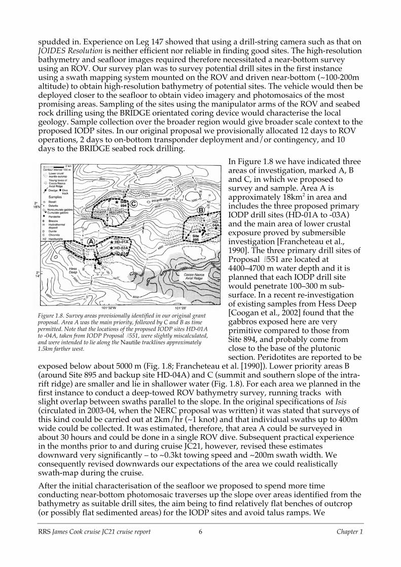
In Figure 1.8 we have indicated threeareas of investigation, marked A, Band C, in which we proposed tosurvey and sample. Area A isapproximately 18km2 in area andincludes the three proposed primaryIODP drill sites (HD-01A to -03A)and the main area of lower crustalexposure proved by submersibleinvestigation [Francheteau et al.,1990]. The three primary drill sites ofProposal #551 are located at4400–4700 m water depth and it isplanned that each IODP drill sitewould penetrate 100–300 m sub-surface. In a recent re-investigationof existing samples from Hess Deep[Coogan et al., 2002] found that thegabbros exposed here are veryprimitive compared to those fromSite 894, and probably come fromclose to the base of the plutonicsection. Peridotites are reported to be
exposed below about 5000 m (Fig. 1.8; Francheteau et al. [1990]). Lower priority areas B(around Site 895 and backup site HD-04A) and C (summit and southern slope of the intra-rift ridge) are smaller and lie in shallower water (Fig. 1.8). For each area we planned in thefirst instance to conduct a deep-towed ROV bathymetry survey, running tracks withslight overlap between swaths parallel to the slope. In the original specifications of Isis(circulated in 2003-04, when the NERC proposal was written) it was stated that surveys ofthis kind could be carried out at 2km/hr (~1 knot) and that individual swaths up to 400mwide could be collected. It was estimated, therefore, that area A could be surveyed inabout 30 hours and could be done in a single ROV dive. Subsequent practical experiencein the months prior to and during cruise JC21, however, revised these estimatesdownward very significantly – to ~0.3kt towing speed and ~200m swath width. Weconsequently revised downwards our expectations of the area we could realisticallyswath-map during the cruise.After the initial characterisation of the seafloor we proposed to spend more timeconducting near-bottom photomosaic traverses up the slope over areas identified from thebathymetry as suitable drill sites, the aim being to find relatively flat benches of outcrop(or possibly flat sedimented areas) for the IODP sites and avoid talus ramps. We
Figure 1.8. Survey areas provisionally identified in our original grantproposal. Area A was the main priority, followed by C and B as timepermitted. Note that the locations of the proposed IODP sites HD-01Ato -04A, taken from IODP Proposal #551, were slightly miscalculated,and were intended to lie along the Nautile tracklines approximately1.5km farther west.

RRS James Cook cruise JC21 cruise report 7 Chapter 1
envisaged sampling the very steep buttresses of rock outcrop directly using the ROV. Atthe same time as surveying for potential IODP sites we would look for optimum sites forBRIDGE rock drilling. The amount of time we proposed to expend in areas B and C woulddepend upon the success of our investigations in area A, but at minimum we wouldconduct a survey in one of the other areas in order to find a suitable back-up site were areaA found to be unsuitable.In the original proposal we planned to use on-bottom long baseline transpondernavigation in area A to ensure the most accurate positioning. However, prior to the cruisewe established that it would be clearly advantageous to use the ultra-short baseline(USBL) navigation built in to Isis which, although it is slightly less precise, is significantlymore reliable and does not necessitate the time-consuming deployment of an on-bottomtransponder network. The USBL navigation provides horizontal accuracies of ~0.5% ofwater depth, i.e. ~±25m at 5000m. Because of the steep slopes and rugged crenulatedtopography of Hess Deep and short range of the NMF acoustic beacons, we would havehad to redeploy the transponder network several times during the cruise (at 1-2 days pertime) to survey the areas proposed.

RRS James Cook cruise JC21 cruise report 8 Chapter 2
Chapter 2. Ship’s Systems2.1 Description of ship-fitted systemsRRS James Cook is fitted with a number of deployment, instrumentation and data loggingsystems. Some of these systems are used to log data at all times whilst others are usedduring each cruise to achieve specific science objectives.The “always on” systems include the Gravity meter, Surmet meteorological dataacquisition, Applanix POSMV ship attitude and position systems, WAMOS wave radar,EA600 single beam echo sounder and the ships gyro which are all logged to IfmersarTechsas data logging system. Also on board is a pCO2 system operated on behalf of PMLwhich logs separately.For cruise JC21 the equipment required for specific science objectives were the deep watermultibeam echo sounder (EM120), Sub Bottom Profiler (SBP120), Sound Velocity Profiler(SVP) and (surface-towed) magnetometer. Available systems that were not used duringJC21 were the EA500 single beam echo sounder, the EK60 “fish finder”, ACDP and theXBT.The deployment systems required for JC21 were the Deep Tow wire through theStarboard gantry for deployment of the BGS rock drill, the CTD wire through thestarboard hydro-boom for deployment of the SVP and the Trawl wire through the Aft Aframe for the rock dredge. The CLAM cable logging and monitoring system was used tolog winch information to the Techsas system when in use.Additional systems installed for the use of the scientific party include the V-sat satellitecommunications system along with the computer network and various public usecomputers and printers attached. Because of the failure of one of the main tracking boardswithin the V-sat system prior to the cruise, and our inability to source any spares at thetime of the Panama portcall, the V-sat system was not available for use during JC21.
Sound velocity probeBecause the speed of sound in water varies depending on depth, temperature and salinityit is necessary to measure the sound velocity at each depth and produce a profile. Themeasurement of sound velocity is very difficult to achieve and so rather than measuringthe speed directly the constituent parameters are measured and a calculation carried outwithin the device.The output from the probe is therefore depth and sound velocity, which has beencalculated from the readings of the pressure sensor, thermometer and conductance meterfor the salinity.For the hydrographic equipment to work as accurately as possible a sound velocity profilemust be obtained in the area where the equipment will be used. For this purpose there are2 SVP probes available on board the ship: an AML device and a Valeport.The profiles used throughout the cruise were obtained using the Valeport probe deployedon the CTD wire through the starboard gantry. The probe is self logging and no data isavailable until the instrument is brought back on board and the log files downloaded fromthe device.Upon reaching Hess Deep a SVP dip was carried out. Unfortunately as the winch systemhad not been used for a period of time several issues arose during this deployment.
RRS James Cook cruise JC21 cruise report 9 Chapter 2
During the first attempt one of the sheaves on the hydro-boom became very noisy at adepth of approximately 750m. As the depth of water at this location was 5000m the probewas retrieved due to the likelihood of permanent damage if the operation continued. Theauto-greaser on the sheave was found to be faulty, causing the bearing of the sheave to bedry and causing the problem. The sheave was manually greased and the faulty auto-greaser replaced.A second deployment was carried out, but when the probe was at approximately 1200m ajoint in the hydraulic system supplying the winch room burst. This caused a loss of oil inthe system and needed repair. The joint was repaired the oil also needed to be filled. Allspilt oil was contained and disposed of correctly. The pipe work on board James Cook ispoorly installed and as a result has put stresses into the system that periodically causebursts of this nature.This fault caused the probe to be stationary at 1200m for a period of 45 minutes afterwhich the probe was taken to a depth of 4800m. When the probe was brought on board itwas found that the data had stopped logging during the stationary period and a furtherdip was needed.The third deployment was successful and the resultant sound velocity profile wasimported into the EM120, SBP120, EA600 systems, and provided to the ROV team for usein their systems.
Kongsberg EM120 multibeam echosounderThe EM120 is used to perform seabed mapping to full ocean depth. The normal sonaroperating frequency of the EM120 is 12 kHz with an angular coverage sector of up to 150°and 191 beams per ping. Achievable swath width on flat bottom will normally be 5 timesthe water depth. The EM120 transducers are linear arrays in a Mills cross configurationwith separate units for transmit and receive.The operator station for the EM120 is a computer in the Main Lab running KongsbergSeafloor Information System (SIS) version 3.3 software on a Windows XP platform. Therehave previously been issues with disk space on the computer system, but since cruise JC15additional hard drives have been installed and there were no problems with disk spaceduring JC21.Because of the depth of water at Hess Deep the EM120 was used for all ship swathoperations, as the higher frequency EM710 system also fitted is only suitable for depth ofless than 1000m. The EM120 was used extensively throughout the cruise both forpreliminary swathing prior to ROV swaths and for opportunistic swathing duringpassages (see section 2.2 below).Previously there have been problems using the EM120 at speeds above 4 knots, and eventhen the quality of the data has been questionable at higher sea states. This is aconsequence of the precise position of the transducer array on the bottom of the ship andthe cavitation caused by the bulbous bow. Fortunately during JC21 the sea was very calmthroughout and good data were acquired, even at speeds of up to 12 knots. Ballasting thebow seems to improve data quality and this was done for the 12-hour swath surveyconducted (at 4kt) when the ship first arrived at the survey area.Position and attitude data is input to the hydrographic suite and then each of the echosounders has offsets so that the depth data collected is referenced to its actual position onthe seabed. Raw data from the swath system were passed to the scientific party whocarried out post-processing on board (see section 2.2 below).

RRS James Cook cruise JC21 cruise report 10 Chapter 2
SBP120 sub-bottom profilerThe Kongsberg SBP120 sub-bottom profiler is an extension to RRS James Cook’s EM120multibeam echo sounder. The EM120 receive-transducer hydrophone array used by themultibeam echo sounder is wideband, and by adding a separate low frequency SBP120transmit transducer and appurtenant electronic cabinets and operator stations, the EM120may be extended to include the sub-bottom profiling capability provided by the SBP120.The primary application of the SBP120 is to image sediment layers sub-surface.Although not of prime importance to the scientific goals of the cruise, during JC21 it wasturned on and logged while the ship was swath-mapping. The data were found to beunusable at speeds greater than 6kt and when using the ship’s thrusters while on station.Logged SBP data files will be examined post-cruise to see whether any information ofvalue to the goals of the cruise can be extracted from them.At the beginning of the cruise there was a problem getting a reliable depth data input tothe SBP120. This was traced to a problem on the Kongsberg network (the hydrographicsuite has its own dedicated network) where the DNS server was not starting correctly andso the SBP could not get its depth data from the EM120. Once this was solved there wereno further problems with the SBP.
Towed magnetometerFor this cruise a new Marine Magnetics SeaSPY magnetometer was installed temporarilyon the ship. The computer in the Deck Lab was used as the deck unit and a cable run tothe port aft quarter where the cable handling and deployment station was placed. Thesoftware provided with the unit is SeaLINK 8.0.As this was a new installation there were inevitably some difficulties. In this case the mainproblem was in getting NMEA data into the computer so that it could be logged with themagnetometer readings rather than requiring that a cross reference to other files to get thisdata after the event. NMEA data, which includes the required GPS output, is broadcast onthe ship’s computer network. However the magnetometer software could not accept thisinput and required a serial input for this information. A small program was written whichread the UDP broadcast data and output the data to a serial port, this output was thenlooped back into another serial port so that the magnetometer software could read it.The magnetometer tow fish is deployed and recovered at a ship speed of 4 knots andneeds to be at least 3 ship’s lengths behind the ship to prevent any effect from the steelhull. The tow fish was therefore deployed to a position 280m behind the ship. This lengthplus the distance from the aft of the ship to the GPS antenna, 50m, is set as a “layback”distance in the software so that the data files contain positions of the tow fish rather thanthe ship.The tow fish was deployed whenever the ship was swath surveying in the Hess Deep area:principally during the two occasions that we entered and left the survey area. Although itis not clear from the documentation what the maximum speed for use of the tow fish is,because the ship’s opportunistic swath surveys later in the cruise were conducted at 10ktthe tow fish was also used at 10 knots. The tension on the towing wire was checked andwas not found to be excessive. It was also checked whether the fish was jerking or liftingout of the water. No problems were found and the magnetometer was used at this speedthroughout.Overall the magnetometer worked well and a permanent installation will be madefollowing the end of cruise JC21.

RRS James Cook cruise JC21 cruise report 11 Chapter 2
Applanix POSMVAll positional and attitudinal data input into the scientific equipment onboard during JC21received these data from the Applanix POSMV, either via NMEA strings distributed asUDP messages on the computer network or via serial RS232 cables.The GPS antennae are mounted on the main mast and the gyro and attitudinal data arefrom a motion reference unit mounted at the xyz centre of the ship.The pitch, roll and heading accuracy is specified as 0.02° (1 sigma). The positionalaccuracy is 0.5–2 m (1 sigma) depending on the differential corrections and the velocityaccuracy is 0.03m/s horizontal.
Ultra-short baseline acoustic navigation (USBL)For the purposes of tracking underwater beacons fitted to various pieces of equipment aSonardyne USBL system is fitted to the ship. The deck unit is sited in the Main Lab and thedetector head fitted to retractable poles which penetrate the ships hull at a point 13m aft ofthe centre reference point. The poles protrude approximately 2 m when deployed.To allow the poles to be deployed there are sea valves to provide the openings andhydraulically operated rams which lower the poles with the sensor head attached.There are two poles and two types of head fitted. The starboard pole has a standard headfitted. The port pole has a larger head which allows the transducers to be slightly furtherapart thus giving greater positional accuracy but sacrificing shallow water operation. Inpractice the shallow water capability does not seem to be affected when using either head.Further information concerning the specifications of the system is not available on boardship and can be requested from NMF in Southampton post-cruise if required.
Gravity meterA Model ‘S’ Air Sea Dynamic Gravity Meter System II was installed during the previouscruise and has been operating and logging since. During the port call in Antigua a basestation tie-in was carried out and it is intended to carry out a further tie-in during the nextport call which could be either Caldera, Costa Rica or Panama.The Gravity meter is setup to log both locally and to broadcast data to the TECHSASlogging system.The Model ‘S’ unit was in operation throughout the entire cruise. The machine requiresvery little in manpower overheads and only required checks to ensure correct operation inthe morning and evening.The specifications of the gravity meter are given below.

RRS James Cook cruise JC21 cruise report 12 Chapter 2
SPECIFICATIONSENSORRange 12,000 mGalDrift 3 mGal per month or lessTemperature Set point 46° to 55°STABILISED PLATFORMPlatform Pitch ±22 degreesPlatform Roll ±25 degreesPlatform period 4 to 4.5 minutesPlatform Damping .707 of CriticalCONTROL SYSTEMRecording Rate 1 HzSerial Output RS-232Additional I/O Ambient Temp, Sensor Temp, Sensor
PressureSYSTEM PERFORMANCEResolution 0.01 mGalStatic Repeatability 0.05 mGalAccuracy at Sea 1.0 mGalMISCOperating Temperature 0°c - 40°cStorage Temperature -30°c to 50°cDimensions 71 x 56 x 84 cmWeight Meter 86kg, Unit 30kg
2.2 Potential field measurements: operationsGravitySea surface gravity field data were obtained with the Micro-g LaCoste Air-Sea GravityMeter onboard and logged for the whole time the ship was in international waters. Thegravimeter was mounted on a stabilised platform and corrected gravity field values for theeffect of the pitch and roll of the ship (see section 2.1 above). Accuracy of the gravimetoroperated at sea is typically 1 mGal or better. Collected data are raw regional gravity field(mGal) and Etövös correction (mGal) with 1Hz sampling frequency. Two types of .csv files(with extensions of .dat and .env respectively) are available for the gravity field data, shipattitude, and navigation. The raw gravity field as measured during the cruise ranges from9190 – 9390 mGal through entire survey area. The gravity data will be corrected by tidaloscillation readings from Costa Rica and Panama ports. Free-air and Bouguer anomalieswill be obtained from the sea surface gravity field data following successful application ofthese corrections and incorporation of navigation and of shipboard and near-bottomswath bathymetry data.
Sea-surface magneticsSea surface magnetic field data were obtained with Marine Magnetics SeaSpy Overhausermagnetometer (see section 2.1 above). The accuracy of this tool is stated at 0.001nT. Itcollects total sea surface magnetic field with 2Hz sampling frequency. It was towed 270mbehind the port side of the ship, and deployed for those periods in which the ship wasapproaching or leaving the survey area, and during the brief swath survey conducted atthe start of scientific operations. The raw magnetic field data range from 31200–32760nTthrough the survey area. In total four sea surface magnetic surveys were carried out:Survey #1 (Julian day 013Z): The magnetometer was deployed underway during the shipswath bathymetry survey upon first arriving at Hess Deep. GPS was not acquired for the

RRS James Cook cruise JC21 cruise report 13 Chapter 2
magnetometer location; hence the magnetic field data only have x-y-coordinates withrespect to the ship’s common reference point (GPS antenna). In general, a laybackcorrection 45.7m astern of the antenna position needs to be added to the length ofmagnetometer cable is (x,y) = (0, 315.7). Data logging during this deploment often neededto be reset due to these issues, so the data sequence is more or less piecemeal and in needof a substantial amount of cleaning and concatenation along with the calculation ofnavigation data. The missing magnetometer coordination (latitude and longitude) will bere-calculated from the juxtaposition of the magnetometer with respect to the ship’s GPS.Survey #2 (024Z): The magnetometer was deployed underway from Station 11 to 12during the ship swath bathymetry survey. The magnetometer was recorded with GPSdata.Survey #3 (031Z): The magnetometer was deployed underway from Station 12 to 13during the ship swath bathymetry survey. The magnetometer was recorded with GPSdata.Survey #4 (038Z): The magnetometer was deployed underway from the Hess Deep to thefinal swath-mapped waypoint (2°31’N 100°36’W) upon leaving the survey area. Themagnetometer was recorded with GPS data.
2.3 EM120 (ship’s) swath bathymetry: operations and processing summaryMultibeam bathymetry data were acquired in Hess Deep upon arriving onsite (013Z),during most Isis operations, during a period of ROV downtime (024Z), and duringtransits to (024Z) and from Hess Deep to Costa Rica (031Z, 038Z) using the hull-mountedEM120 system on RRS James Cook. Very basic processing of these data resulted in a grid(100m x 100m spacing) of bathymetry data within Hess Deep and in surrounding areas tothe SW, N and NE (Fig. 2.1). Additionally, the acquisition of bathymetry data duringtransits to and from Costa Rica also yielded swath coverage of the northern wall of HessDeep at least as far east as 100º40’W. Combined with existing bathymetry data, these datacover most of the Hess Deep area (Fig. 2.2). New data provide higher-resolution images ofwell-studied parts of Hess Deep, including the nadir of the Deep itself, and the intra-riftridge (existing datasets stored in the LDEO bathymetry database are gridded at 200 m).The survey lines to the southwest also show a northeast-southwest trending depression to
Figure 2.1. Bathymetry map of EM120 swath data collected during the whole of cruise JC21. The area shows the northern partof the Galapagos Gore, with Hess Deep at the WSW end of the area mapped (2°15’N, 101°30’W).

RRS James Cook cruise JC21 cruise report 14 Chapter 2
the south of the main rift axis. Both NW-SE- and NE-SW-trending features can beobserved within this depression. Swath lines collected to the NE of the main study areashow a series of en echelon ESE-WSW trending ridges. Each ridge is approximately ~30km long (E-W) and ~10 km wide (N-S).Because of the limited processing applied to these data, they still contain noise,particularly at the outer parts of each swath. This noise is usually manifested as largenegative spikes (i.e., deeper than surrounding seabed depth). There are also some badpings, particularly in lines acquired at higher speeds: see section 2.1 above), which resultin stripes of spurious returns perpendicular to the swath tracks.
Figure 2.2. EM120 swath bathymetry map of Hess Deep, from data collected during cruise JC21.

RRS James Cook cruise JC21 cruise report 15 Chapter 3
Chapter 3. The Isis Remotely-OperatedVehicle
3.1 The Isis vehicleIsis is a deep-diving ROV (Fig. 3.1)constructed for the UK marine sciencecommunity by engineers at the WoodsHole Oceanographic Institution, USA.Isis was delivered in 2003 and is a near-identical clone of ROV Jason 2 operatedby WHOI for the US community. Thevehicle is operated by Sea Systems, partof the NERC National Marine FacilitiesDivision at the National OceanographyCentre, Southampton. ROV Isis has adepth rating of 6500m.The vehicle frame is constructed from acombination of hollow and structuralsection aluminium, welded together toform a rigid structure. The frame iscorrosion protected with anodes andground-fault detectors. Nylon skids and'D' rubber fenders protect the framefrom impact damage during normaloperations. Buoyancy is provided bysyntactic foam modules (density500kg/m3) finished with elastomericcoating bolted directly onto the vehicleframe. Most electronics are housed intitanium pressure vessels withinstruments connected to oil-filledelectrical junction boxes via pressurebalanced, oil-filled cable hoses. Isis has a large front retractable tray for the collection ofscientific samples. Smaller swivel trays at the sides can carry additional samples. Amaximum payload of ~150kg (weight in air) can be recovered. Propulsion is provided bysix reversible 3.7kW thrusters, arranged with two thrusters each providing fore/aft,vertical, and lateral motion. The vehicle is controlled from the surface via a tether, withthree optical fibres for data and three conductors at 3kV for power, linked to a modularcontrol room with space for three operators/pilots and four or more scientists. Thisscience control area includes equipment for event logging, video and data recording to a7TB data store, record keeping and enables scientists to work directly with the pilotsduring survey and sampling operations. Detail of the video and still camera systems isgiven in Appendix A06. The information flow for Isis navigation, swath and other data isshown in Figure 3.2. In addition, the Isis package includes a two-container workshop withtools and spares, a winch and cable drum with 10km cable and an electro-hydraulic powerunit for the winch and launching gantry. The package also includes eight guys who like todrink beer and chase girls.
Figure 3.1. View of the forward part of the Isis vehicle, about tobe launched from the port side of RRS James Cook. Note samplebaskets on the sled, two manipulator arms, and array offorward-looking video and still cameras.

RRS James Cook cruise JC21 cruise report 16 Chapter 3
Figure 3.2. Isis information flow
Outline technical specifications for Isis are listed below:
• Length: 2.7 m; Width: 1.5 m; Height: 2.0 m; Weight: ~3T• Max. working depth: 6500 m• Max electric power 18 kW at 6500 m (~18kW lost in cable).• Cable voltage: 3000V• Maximum forward and lateral speed: 0.75m.s-1 (1.5kt).• Autopilot functions include:
Auto depth (to +/- 1m)Auto altitude (to +/- 1m)Auto heading (to <+/- 1˚)
• Hydraulic power unit 3.7kW for manipulators, trays etc.• Power management between thrust, lights, hydraulics and user instruments to maximise use of powerat depth.• Forward tray and two side trays with hydraulic actuators.• Quartz pressure transducer for depth with precision of <0.1%.• Acoustic altimeter to give height off the sea bed when within 200m.• Multi-channel serial, Ethernet and video communications over optical fibre.
Cameras and lights on Isis:• Three Metal halide lights of 400W each provide the main forward lighting• A 3-chip 850 line colour camera with a 14x zoom provides broadcast-quality video.• A 3.34 Mpixel digital still camera with a 4x zoom for publication-quality pictures.• Two standard resolution low light colour cameras with 12x zoom and pan and tilt control provide the
pilot and scientists with their own general coverage video.• Two red lasers mounted 10 cm apart allow picture scaling.• Other video cameras monitor the tether and the rear of the vehicle.
Sonar systems on Isis• SM2000 echo-sounder• The MS1000 echosounder 675kHz single beam device
Hydraulic Manipulators: The “Predator”• Base of Arm: Pivot and swivel• Shoulder: Pivot• Elbow: Pivot• Wrist: Pivot at 90˚with continuous rotation• Claw: Pinches, simple ‘grab’.

RRS James Cook cruise JC21 cruise report 17 Chapter 3
3.2 Isis operational strategyThe three main proposed sites of IODP Proposal #551 (HD-01A to -03A) are located on thesouth-dipping slope that rises to the north of the 5400m-deep nadir of Hess Deep, andthus formed the primary focus of our investigations (see section 1.5). This corresponds toarea ‘A’ of Figure 1.8. Later in the cruise we also surveyed a smaller area on the southernflank of the intra-rift ridge: area ‘C’ of Figure 1.8. In each of these areas we first of allemployed the ROV to acquire high-resolution swath bathymetry (section 3.3), and thenconducted near-bottom operations to sample the sections just surveyed.Swath surveying of area A was done on Isis dives 67, 68 and 71, and of area C on dive 74.Near-bottom sampling of area A was undertaken on dives 69, 70, 72 and 73. Area C wassampled during dives 75 and 76. Near-bottom dive 78 was made on the northern part ofthe summit of the intra-rift ridge, and relied upon the much lower resolution EM120swath bathymetry to guide navigation and sampling, as was dive 77, which was locatedon the narrow saddle at the centre of the intra-rift ridge. Track lines for these dives areshown in Figures 3.3 and 3.4.
Figure 3.3. Isis dives in area A.

RRS James Cook cruise JC21 cruise report 18 Chapter 3
Figure 3.4. Isis dives in area C.
3.3 Isis swath acquisition and processingThe bathymetry surveys of Isis dives 67, 68, 71 and 74 used the Kongsberg SM2000 sonarswath bathymetry system mounted on the vehicle to produce high-resolution bathymetricmaps of the seafloor. The SM2000 system emits 128 ultrasonic beams over a swath of 120°perpendicular to the Isis ROV heading. The system receives reflected returns from eachbeam and calculates the range, direction and intensity of the sonar returns. Thisinformation is displayed in real-time in the ROV control vans for watchstanders (Fig. 3.5).Meanwhile, ship and ROV navigation and ROV pitch, roll, yaw and depth data are alsocollected.
Dives 67, 68 and 71 were run in aN-S direction, up and down theslope of area A. Dive 74, on thesouthern flank of the intra-riftridge, was run E-W, in part tominimise the amount of time lostin turning the vehicle. Briefcrossing lines were run for eachdive to assess inter-swath errors;typically differences were foundto be no more than 1-2m betweenadjacent swaths. This is mostlikely due to an uncorrected staticpitch error. These will be removedby further processing post-cruise(see below).For each of the mapping dives Isiswas towed at 100m altitude, the
optimum depth determined both for data quality and swath width on our Coiba Ridgetest deployment (dive 66) during our transit at the start of the cruise (see Chapter 6 and
Figure 3.5. Screenshot of MS2000 acquisition software showing raw sonarreturns from one ping. Depths are autopicked. Note the poor return fromthe left-hand extremity of the scan; no depth data would be picked fromhere. Instead, the system may pick spurious returns from the higher-amplitude noise at far left.

RRS James Cook cruise JC21 cruise report 19 Chapter 3
Appendices A05 and A06). Swath widths for the N-S transects varied from ~70m up to300m, though a 200m wide swath of useable data was typical (i.e. 2 x towing altitude). Forthe E-W transects it was slightly less – typically 175m – and asymmetric with respect to thevehicle position (much narrower up-slope). Data from the E-W transects were, however,less noisy than for the N-S lines, probably because the vehicle was more stable and easierto fly. The spacing of swath lines was 150-200m.The acquisition software for the SM2000 sonar is the Kongsberg MS2000 software package.The Caraïbes data processing system takes input from the MS2000, together with thenavigation and ROV attitude data, and merges it with the sonar range and direction datato produce xyz coordinate data. This system is also used to clean and smooth navigationdata and to remove noise and other ‘inappropriate’ sonar returns from the data set.Smoothed USBL navigation was used for all onboard bathymetry processing becauseDoppler navigation files could not be read by the Caraïbes software. This producedaccurate swath positioning accurate to within approximately 10m after significantsmoothing, but errors much greater than the nominal 25m expected from USBLspecifications on short time scales. In principle, Caraïbes is supposed to correct thebathymetry data for attitude variations, but significant roll artefacts are still apparentperpendicular to the line direction. These artefacts degrade vertical resolution as much as5-10m at the edges of swaths, and will need to be removed post-cruise. We also noticed a1-2m systematic depth variation that varies with Isis track direction when going upslopeor downslope. This is most likely due to an uncorrected static pitch error. Finally, high-amplitude instrument generated noise during swath acquisition resulted in a largenumber of bad picks of seabed reflection, requiring significant data cleaning; ~18% of datapoints were removed during this process. The cleaned bathymetry data is merged withsmoothed navigation and gridded with a spacing of 4m to produce the final bathymetrymaps shown in Figures 3.6 and 3.7.
Figure 3.7. SM2000 bathymetry map of area C (southern slopes of the intra-rift ridge).
RRS James Cook cruise JC21 cruise report 20 Chapter 3
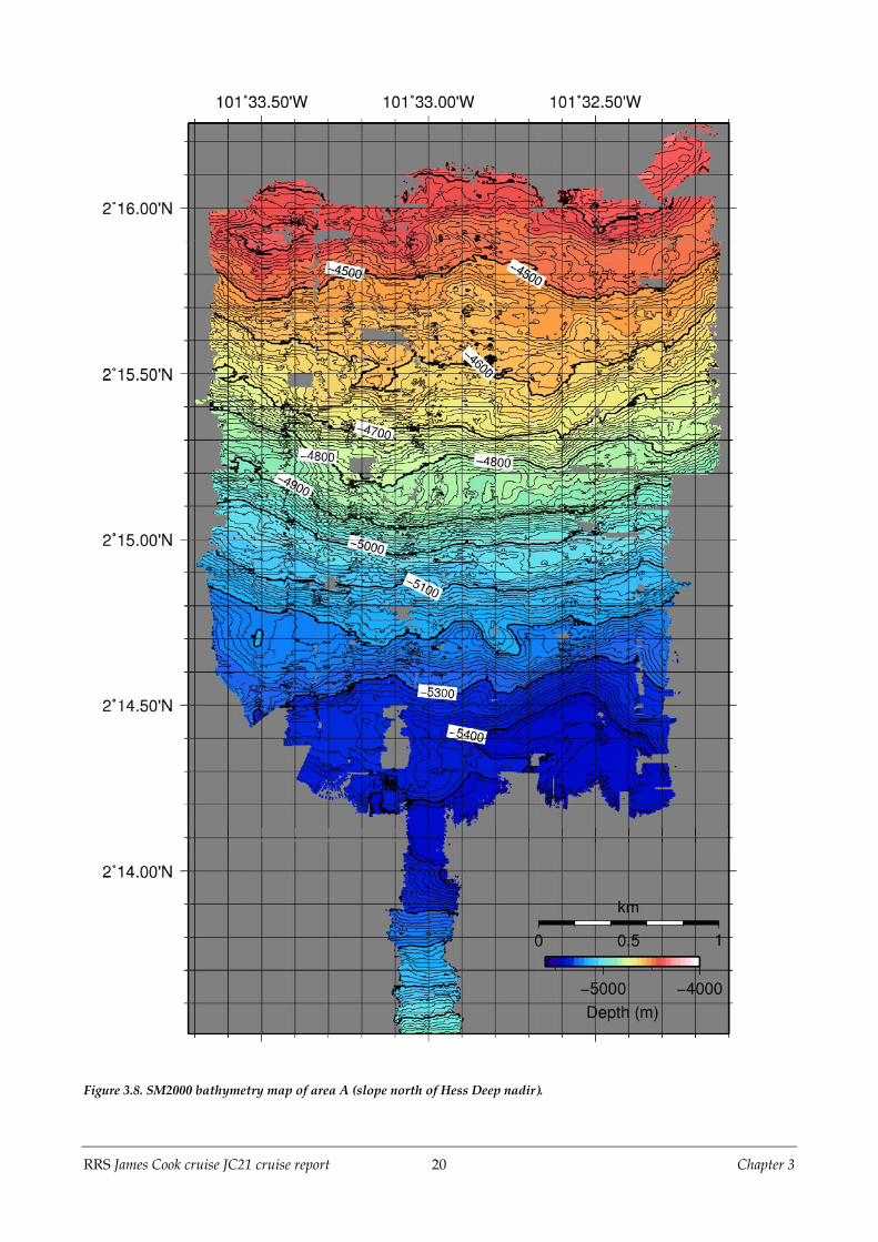
Figure 3.8. SM2000 bathymetry map of area A (slope north of Hess Deep nadir).

RRS James Cook cruise JC21 cruise report 21 Chapter 3
Area A (2°13.5’N to 2°16.2’N latitude, 101°32.1’W to 101° 33.65’W longitude)Area A (Fig. 3.8) mainly stretches from the nadir of the Hess Deep Rift at 5482m below sealevel to the north at a contour level of 4400m. The bathymetry of this area essentiallytrends monotonically from the deepest point in the south to the highest level in the northand contours generally follow E-W orientations. At a slightly greater level of detail thecontours are slightly concave to the north, so that areas directly east or west from thecentre of the swathed area tend to be at greater depths below sea level. The average slopefrom the deepest spot to the top of the area is 18°. We initiated mapping in Area A with asingle swath that commenced on the north-facing slope south of the nadir of Hess Deep(Fig. 3.8). This area is not otherwise described here because no other work was performedin that section.The gross structures in the ~3 x 3km area are a series of relatively flat benches and steeperslopes that generally trend E-W and thus correspond to contour levels. The benchesroughly occur over 5300 to 5200m, 5100 to 5000m, 4900 to 4800m, and 4750 to 4550m, withthe steeper slopes above and below. Particularly steep areas that proved fertile for outcropand sampling were between 5000 to 4850m on the west side of the area and the equivalentslope between 4950 and 4860m in the eastern half. Another productive steeply dippingarea was between depths of 4820 and 4700m across the whole width of the mapped area.The section of the area shallower than 4700m had overall gentler slopes and includes flatprotrusions to the south at 101°32.15’W and 101°32.65’ around the 4600-4700 m level.There is a local high approximately 100m above surrounding terrain in the NW corner ofthe area. Maximum gradient maps and angled illumination maps (Appendix A03) showboth the flatter benches and steeper areas described.Second-order features of the area include a set of ridges and valleys from NE to SWmaking up spaced lineaments, especially pronounced in the eastern half of the area. Thesecut the benches and overall E-W trend of the contours but are evident in the angledillumination maps and the 3-D visualisation of the bathymetry. Of particular interest,because of subsequent intensive rock sampling, is the lineament trending from 2°15.2’N101°32.8’W to 2°15.65’N 101°32.2’W. Other parallel lineaments are spaced 200-400m toeither side.
Area C (2°16.95’N to 2°18.15’N latitude, 101°32.8’W to 101°31.45’W longitude)Area C (Fig. 3.7) consists mainly of the upper portion of the steep slope to the south of thewestern part of the intra-rift ridge. Again, the bathymetry of this area essentially trendsmonotonically up from the deepest point in the south to the highest level in the north andcontours generally follow E-W orientations. Single N-S trending swaths were added to agenerally E-W elongate area at the SW and NE corners of the overall area. Coverage ispredominately in the middle third of the rectangular area defined above. The main areacovered with five E-W adjacent lines is 2000m E to W and 850m from N to S. Averageslope from the deepest spot to the top of the area is 35°, with the steepest slopes in themiddle of the swathed area.The major bathymetric features of Area C are significant N-S trending ridges with adjacentvalleys and chutes that occur at: 101°31.6’W from 3100 to 3300m; 101°31.54’W from 3400 to3500m; 101°31.87’W from 3200 to 3400m; 101°32’W from 3350 to 3800m; and 101°32.35’Wfrom 3500 to 3650m. In addition, there is a long ridge trending 030° in the SW corner of thearea that has a more subtle bathymetric expression, but was followed and sampled forover 500m horizontally and 300m vertically during Isis dive 75 (Fig. 3.7).

RRS James Cook cruise JC21 cruise report 22 Chapter 3
3.4 Use of a deep-towed magnetometer on IsisIn addition to the measurements made using the towed shipboard magnetometer (section2.1), magnetic field data were also obtained using a vector three-axis Honeywell HMR2300Magnetoresistor magnetometer housed on Isis. This was lent to us by Maurice Tivey(WHOI). For each dive, Isis carried out a calibration turn during the descent of the vehicleprior to the survey. The calibration data can then be used to correct the measuredmagnetic field for the effects of the vehicle. Of the twelve Isis dives in the survey area, datawere collected for all but dive 68, for which the instrument had been removed because of acable problem on the preceding dive. On dive 73 magnetometer data for the first 20 hoursof the survey were not recorded because of a data logging problem. Detailed summaries ofoperations are described in Appendix A02.All data were merged and processed based on the time-based data sequences, includingmagnetic field measurements, navigation, and vehicle attitude data. The data decodingand sorting were done using perl scripts written onboard to construct proper format filefor the calibration calculation on MATLAB programs authored by Maurice Tivey. Thedetails of the onboard data processing, mainly about the calibration calculation processes,together with the scripts for decoding Isis magnetic data to carry out this calculationprocesses are provided in Appendix A02.With successful calibration of the magnetic data, post-cruise magnetic data analyses can bedone to obtain regional magnetic anomaly information. These analyses will includecorrections of: along-track bathymetry, slope (tilt) angle, diurnal effects with data fromterrestrial base station, and IGRF. It should be noted that diurnal correction is particularlyimportant for high resolution magnetic analyses around the equatorial area. This isbecause the ionization of ionosphere by sun during daytime results in large DC offset inthe Earth’s geomagnetic field, which is approximately ± 50 nT. The inversion and forwardcalculations will be carried out to produce grid map of anomaly and magnetizationdistribution. The Gaussian deconvolution routine will contribute to detect the threedimensional distribution of these parameters.
3.5 Isis near-bottom operationsThe swath bathymetry mapping described in sections 3.2 and 3.3 formed the basis for adetailed near-bottom sampling programme using Isis. The configuration of the vehicle waschanged by removing the SM2000 multibeam sonar array and other non-essential items inorder to maximise the payload of rocks. Baskets with 6-8 slots marked with uniqueidentifier codes were constructed for us by the Isis team and these were mounted on thevehicle sled (Fig. 3.1).Dives 69 and 70 sampled the areas swath mapped in dives 67 and 68 respectively. Dive 72started to sample along the area of swath dive 71, but had to be aborted for us to make theemergency transit to Costa Rica on 24th January (see Chapter 6). Dive 73, the first afterreturning from Costa Rica on 31st January, sampled in greater detail between dives 69 and70, and then completed the upper part of the dive 71 swath area (the NW corner of areaA). Dives 75, 76 and 78 were located on the western part of the intra-rift ridge, and dive 77on the central saddle.Dive tracks, together with a summary of the lithology of the samples collected, are shownin Figures 3.9 and 3.10. Detailed descriptions and photographs of the rocks collected areincluded in Appendices A08-A10, and images of outcrops are in Appendix A07.
RRS James Cook cruise JC21 cruise report 23 Chapter 3
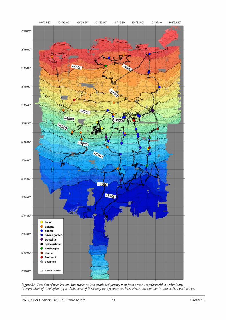
Figure 3.9. Location of near-bottom dive tracks on Isis swath bathymetry map from area A, together with a preliminaryinterpretation of lithological types (N.B. some of these may change when we have viewed the samples in thin section post-cruise.

RRS James Cook cruise JC21 cruise report 24 Chapter 3
Figure 3.10. Location of near-bottom dive tracks on Isis swath bathymetry map from area C, together with a preliminaryinterpretation of lithological types (N.B. some of these may change when we have viewed the samples in thin section post-cruise.
Samples were collected using the manipulator arms of Isis. Great care was taken to ensurethat they were taken from in situ outcrop rather than the far easier task of picking up loosematerial, however ‘local’ it appeared. Because of the significant amount of talus presentand even greater coverage of pelagic sediment, outcrops of in situ bedrock were often fewand far between. Such outcrops as there were were often visible only on their steep sides,their upper parts being blanketed in pelagic sediment. This is one reason why we foundthe BRIDGE drilling operations to be so difficult: with a downward-looking video, it washard to spot outcrops even when directly over them. Only in a few places, more typicallyon the intra-rift ridge, were outcrops more extensive than a few tens of square metres, andin these places they were often extremely steep.Rock types recovered by Isis range from harzburgite, dunite, troctolite, olivine gabbro andother gabbro lithologies, to dolerites and basalts. In all 145 samples totalling 760kg werecollected, with the largest single dive haul being 157kg (dive 73, with 27 samples). Themanipulator arms were strong enough to pick up samples as large as 45cm long andweighing up to 27kg; these would typically have to be laid on top of the baskets.Our detailed mapping (Figs. 3.9 and 3.10) indicates a more complex distribution of rocktypes across Hess Deep than suggested by previous investigations, and requiressignificant refinement of presently accepted models for the structure and tectonicevolution of the rift. Importantly however, the ocean crustal stratigraphy at Hess Deep can

RRS James Cook cruise JC21 cruise report 25 Chapter 3
still be re-constructed enabling primary science questions regarding fast-spread lowercrustal accretion mechanisms to be addressed in post-cruise study of the samplescollected. The proposed IODP drilling (Proposal 551-Full5, Gillis et al.) will be enhancedand strengthened by our new findings with more confidently established geologicalcontext of potential drill sites.Interpretation of the distribution of rock types and of the morphology and structure ofHess Deep, whether on a local or regional scale, is beyond the scope of this report and willbe done post-cruise.
RRS James Cook cruise JC21 cruise report 26 Chapter 4
Chapter 4. The BRIDGE Seabed RockDrill
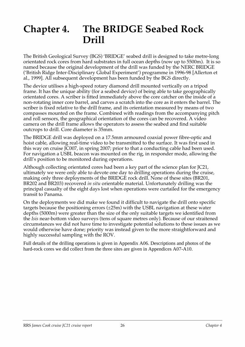
The British Geological Survey (BGS) ‘BRIDGE’ seabed drill is designed to take metre-longorientated rock cores from hard substrates in full ocean depths (now up to 5500m). It is sonamed because the original development of the drill was funded by the NERC BRIDGE(‘British Ridge Inter-Disciplinary Global Experiment’) programme in 1996-98 [Allerton etal., 1999]. All subsequent development has been funded by the BGS directly.The device utilises a high-speed rotary diamond drill mounted vertically on a tripodframe. It has the unique ability (for a seabed device) of being able to take geographicallyorientated cores. A scriber is fitted immediately above the core catcher on the inside of anon-rotating inner core barrel, and carves a scratch into the core as it enters the barrel. Thescriber is fixed relative to the drill frame, and its orientation measured by means of twocompasses mounted on the frame. Combined with readings from the accompanying pitchand roll sensors, the geographical orientation of the cores can be recovered. A videocamera on the drill frame allows the operators to assess the seabed and find suitableoutcrops to drill. Core diameter is 35mm.The BRIDGE drill was deployed on a 17.5mm armoured coaxial power fibre-optic andhoist cable, allowing real-time video to be transmitted to the surface. It was first used inthis way on cruise JC007, in spring 2007; prior to that a conducting cable had been used.For navigation a USBL beacon was mounted on the rig, in responder mode, allowing thedrill’s position to be monitored during operations.Although collecting orientated cores had been a key part of the science plan for JC21,ultimately we were only able to devote one day to drilling operations during the cruise,making only three deployments of the BRIDGE rock drill. None of these sites (BR201,BR202 and BR203) recovered in situ orientable material. Unfortunately drilling was theprincipal casualty of the eight days lost when operations were curtailed for the emergencytransit to Panama.On the deployments we did make we found it difficult to navigate the drill onto specifictargets because the positioning errors (±25m) with the USBL navigation at these waterdepths (5000m) were greater than the size of the only suitable targets we identified fromthe Isis near-bottom video surveys (tens of square metres only). Because of our straitenedcircumstances we did not have time to investigate potential solutions to these issues as wewould otherwise have done; priority was instead given to the more straightforward andhighly successful sampling with the ROV.Full details of the drilling operations is given in Appendix A06. Descriptions and photos of thehard-rock cores we did collect from the three sites are given in Appendices A07-A10.

RRS James Cook cruise JC21 cruise report 27 MacLeod et al. [2008]
Chapter 5. Sample Descriptions
5.1 IntroductionAll samples were described on board based on macroscopic observations made on cutsurfaces. The following information was recorded for each sample in spreadsheets:
• rock name• primary mineralogy• mode (visual estimate)• minimum, maximum and average grain size of each of the primary phases• habit of each of the primary phases• magmatic deformation intensity• crystal-plastic deformation intensity• cataclastic deformation intensity• vein density• fracture density• total alteration• alteration phases
In addition, a summary sheet was prepared for each sample containing sample location,outcrop description, sample picture and a brief summary of lithology, structure andalteration.
5.2 Igneous petrologyIgneous petrology descriptions were done by Johan Lissenberg, Kerry Howard, HeidiHansen and Masako Tominaga. Each sample was assigned a rock name using thefollowing criteria, which closely follow those used during (I)ODP hard rock legs anddescribed in Blackman et al. (2006).Plutonic rocks are classified by pre-alteration mineralogy and mode largely followingIUGS guidelines (Fig. 5.1; Streckeisen, 1974):Harzburgite: >95% olivine+orthopyroxene, olivine>orthopyroxene, olivine <90%Dunite: >90% olivineTroctolite: olivine+plagioclase >95%, olivine >10%, plagioclase >10%Olivine gabbro: olivine+plagioclase+clinopyroxene, none of which <5%Gabbro: plagioclase+clinopyroxene >95%, plagioclase >10%, clinopyroxene >10%Gabbronorite: plagioclase + clinopyroxene + orthopyroxene, none of which <5%
Following Leg 304/305 procedures (Blackman et al., 2006), we used several modifiers forrock names:‘Olivine-bearing’ is used when olivine in gabbroic rocks forms between 1 and 5 % of themode.‘Orthopyroxene-bearing’ is used for gabbroic rocks with orthopyroxene contents between1% and 5%.‘Oxide’ is used as a modifier for gabbroic rocks if oxides form >2% of the mode.

RRS James Cook cruise JC21 cruise report 28 MacLeod et al. [2008]
‘Disseminated oxide’ is used for gabbroic rocks if oxides form between 1% and 2% of themode. ‘Plagioclase’ is used as a modifier for dunites where plagioclase forms <10%.In addition to the classification of plutonic rocks, we used ‘basalt’, ‘dolerite’ and‘cataclasite’. Basalt was used to describe aphanitic rocks, which may contain vesiclesand/or phenocrysts, and may have glassy rims. We thus used basalt as a textural term;formal classification using the IUGS compositional scheme for volcanic rocks awaits theacquisition of geochemical data. Dolerite was used to describe fine-grained rocks withsub-ophitic to ophitic textures and acicular plagioclase. Basalt and dolerite were assignedmodifiers based on phenocryst content; ‘aphyric’ for rocks with <1% phenocrysts and‘sparsely phyric’ for rocks with 1%-5% phenocrysts.Cataclasite was used for rocks that suffered significant cataclastic deformation (see below);generally, no progenitor could be distinguished for these rocks. If the igneous rock typecould be deduced, the term was instead used as a modifier: e.g. ‘cataclastic dolerite’.
Rocks were assigned a grain size based using the following scale:Fine-grained: average grain size <1 mmMedium-grained: average grain size 1-5 mmCoarse-grained: average grain size 5-30 mmPegmatitic: average grain size >30 mm
Figure 5.1: Classification scheme for plutonic igneous rocks after Streckeisen [1
RRS James Cook cruise JC21 cruise report 29 MacLeod et al. [2008]
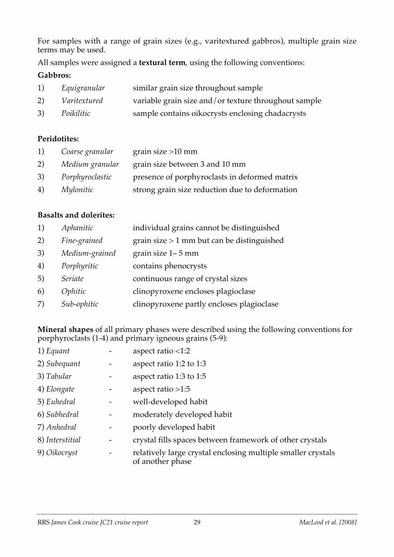
For samples with a range of grain sizes (e.g., varitextured gabbros), multiple grain sizeterms may be used.All samples were assigned a textural term, using the following conventions:Gabbros:1) Equigranular similar grain size throughout sample2) Varitextured variable grain size and/or texture throughout sample3) Poikilitic sample contains oikocrysts enclosing chadacrysts
Peridotites:1) Coarse granular grain size >10 mm2) Medium granular grain size between 3 and 10 mm3) Porphyroclastic presence of porphyroclasts in deformed matrix4) Mylonitic strong grain size reduction due to deformation
Basalts and dolerites:1) Aphanitic individual grains cannot be distinguished2) Fine-grained grain size > 1 mm but can be distinguished3) Medium-grained grain size 1– 5 mm4) Porphyritic contains phenocrysts5) Seriate continuous range of crystal sizes6) Ophitic clinopyroxene encloses plagioclase7) Sub-ophitic clinopyroxene partly encloses plagioclase
Mineral shapes of all primary phases were described using the following conventions forporphyroclasts (1-4) and primary igneous grains (5-9):1) Equant - aspect ratio <1:22) Subequant - aspect ratio 1:2 to 1:33) Tabular - aspect ratio 1:3 to 1:54) Elongate - aspect ratio >1:55) Euhedral - well-developed habit6) Subhedral - moderately developed habit7) Anhedral - poorly developed habit8) Interstitial - crystal fills spaces between framework of other crystals9) Oikocryst - relatively large crystal enclosing multiple smaller crystals
of another phase

RRS James Cook cruise JC21 cruise report 30 MacLeod et al. [2008]
5.3 Structural petrologyStructural descriptions were done by Benoît Ildefonse, using the same conventions asthose defined in the Methods chapter of the IODP Expedition 304-305 Proceedings(Blackman et al., 2006), and derived from several earlier hard rock ODP Legs. Theseprocedures may be used with both crustal and mantle rocks. Each structural feature(magmatic and solid state foliations; cataclastic deformation intensity; vein density;fracture density) was characterized by a value on a semi-quantitative, empirical intensityscale (Fig. 5.2). This characterization was complemented by a brief description wheneverappropriate. Orientations of planar features in orientated Bridge Drill cores weremeasured in the core reference frame, with the scribed mark indicating a provisionalNorth.
Figure 5.2: Scales used to describe deformation intensity

RRS James Cook cruise JC21 cruise report 31 MacLeod et al. [2008]
5.4 Metamorphic petrologyDescriptions of the metamorphic and alteration assemblages were done by MichelleHarris, Damon Teagle and Kathy Gillis.First, the overall alteration intensity of the sample was described and quantified on a scaleof fresh (<1%), slight (<10%), moderate (10-50%), high (50-90%) and complete (>90%).Alteration was then described for each of the primary igneous phases (where applicable),recording the secondary phases and estimates of the percentage of the mineral replacedwhere possible. General alteration features of the sample were recorded as comments.Veins were logged separately with vein thickness, composition, morphology, cross cuttingrelationships, halo and halo composition all recorded.

RRS James Cook cruise JC21 cruise report 32 Chapter 6
Chapter 6. Daily Narrative
The purpose of this section is to give a brief summary of operations on a daily basis,written at the time. It includes any other happenings of interest, and gives a briefperspective on how our ideas developed as the cruise progressed, both with respect tooperational strategy and our scientific thinking. A visual summary of all operations isgiven in Figure 6.1. Of the 24 allocated days of science time, approximately 14.5 days weredevoted to Isis operations, 1 day to drill operations, and 8.5 days were lost to variousequipment problems and (most of all) to the need to suspend operations in the survey areain order to make a compassionate evacuation of a crew member to Costa Rica.
Sunday 6th January 2008 (2008/006Z)In port, at a bunkering berth at the Rodman Panamanian naval station, 8°57.10’N 79°34.38’W,then set sail for survey area (start cruise JC21). Weather hot and sunny; seas calm.The last members of the shipboard party, including the PSO, arrived in Panama in theearly hours of the morning of 6th January and were brought straight onboard RRS JamesCook. The PSO was immediately informed of the situation regarding the communicationsfrom the vessel, viz. that the V-sat communications system that normally provided a liveinternet/e-mail/phone link had failed and that replacement parts for the system could notbe sourced within a reasonable period. Although this had been known by Southamptonfor more than a week, neither the PSO nor the Master had been informed ahead of time.Ship to shore communications for the duration of the cruise will be restricted to the sat-Bsatellite phone and fax from the bridge only, though attempts will be made to establish alimited e-mail link in due course.
Figure 6.1. Gantt chart summarising operations during cruise JC21.

RRS James Cook cruise JC21 cruise report 33 Chapter 6
The PSO was informed by the Master that the ship had been asked to vacate the bunkeringberth it was currently occupying by noon local time (GMT-5). No indication had beengiven as to when or where another berth would be found. Given that all personnel werenow on board ship, and all provisioning completed, it was decided to depart for sea assoon as possible, The science party were informed, and had a brief opportunity to makephone calls from public payphones near the dock before the gangway was raised inpreparation for the ship’s departure.RRS James Cook accordingly cast off her moorings at 1230 local time (006/1730Z), andcruise JC21 commenced. She passed beneath the Bridge of the Americas and set sail for thesurvey area, 18 hours ahead of the original departure time. At a cruising speed of 11kttransit to Hess Deep is estimated at approximately 5 days. A safety briefing was held inthe afternoon and the science party signed the ship’s muster.
Monday 7th January 2008 (2008/007Z)Transit to Hess Deep, interrupted by a test deployment of Isis (dive #66). Local noon fix (GMT-5):5°33.4’N 81°52.1’W; average speed 12.0kt; distance travelled 268nm; weather hot and sunny, seascalm..The Isis group requested that they be allowed to carry out a wet test of the ROV. Noting(from global satellite bathymetry maps) that coincidentally we were close to a shallowregion – Coiba Ridge – we asked if the scope of this test could be widened and a shortbathymetry survey conducted. This had several aims: to calibrate the ROV swathbathymetry system; to make an assessment of an optimum towing altitude; to give thescience party some idea of what would be required of them when the survey properstarted; and, not least, to give Donna, Pierre, Steve and Masako a test data set to gainexperience of data processing prior to arrival on site.The sound–velocity probe was deployed at 5°33.43’N 81°52.15’W (744m water depth) andrun to 700m. With the ship’s EM120 swath bathymetry now calibrated, a brief (~1 hour)swath survey of a conveniently nearby seamount (295m water depth) was conducted untilthe Isis team were ready to deploy the ROV. Isis was initially launched at 007/2018Z but aproblem was immediately found with a console in the control shack. The vehicle wasretracted into its A-frame until the panel was exchanged. It was relaunched at 007/2057Zand wet tests conducted. This being satisfactory, the ROV was taken down to mid-waterdepths and a series of turns (‘Tivey turns’) conducted in order to calibrate themagnetometer. A short survey was then carried out to calibrate the SM2000 swathbathymetry. Isis was towed at 100m altitude from 5°30.0’N 81°51.8’W to 5°30.0’N81°51.6’W (approximately 350m W to E) and then back over a reciprocal course. Bycomparing the two profiles any misalignment of the swath sensor can be identified andcorrected for. Isis was towed at approximately 0.4kt, so each pass took approximately 30minutes, and 10 minutes to turn the vehicle around. Part of the same swath was also runagain at 150m altitude, but it was found that the bottom detection was poor at this heightand the swath width obtained was actually narrower than that acquired at 100m towingaltitude. The doppler system actually detected seafloor at up to 192m altitude, but thesignal was inconsistent. At the end of the survey the ROV was taken down to the seabedbriefly to give the science party experience of the kind of images visible on the differentcamera systems carried on board Isis (rippled sediments and white, probably biological,mats). The ROV was brought on deck again at 008/0223Z, and the transit to Hess Deepresumed. The total time of the Coiba Ridge test survey was approximately 6 hours.Ship’s clocks were retarded one hour on Monday night, to GMT-6.

RRS James Cook cruise JC21 cruise report 34 Chapter 6
Tuesday 8th January 2008 (2008/008Z)Transit to Hess Deep. Local noon fix (GMT-6): 5°05.0’N 84°23.3’W; average speed 10.2kt; distancetravelled 158nm (total distance 426nm); weather heavy rain, light-moderate seas.In the morning a one hour test deployment of the BRIDGE rock drill was made by the BGSteam. Problems were found with the flush pump and with the echosounder, but thesewere not thought to be serious.Kathy gave a talk to the science party explaining the regional setting of Hess Deep andreviewing previous expeditions to the area. Donna then gave a brief review of yesterday’sIsis test dive. She and the ‘GMTers’ (Pierre, Steve, Masako) are working on the SM2000swath data we collected and are making good progress towards producing a preliminarybathymetry map.In attempting to print out a base map of the existing bathymetry of the survey area, wefound out that the A0 plotter on board is only able to print in monochrome: the colourprint heads are broken and no spares are on board. The PSO was told by the NMFpersonnel on board that the problem had been known about since cruise JC19 and hadbeen reported to Southampton, but that nothing had been done. Our ability to print incolour is now restricted to an A3 inkjet and A4 colour laser printers.
Wednesday 9th January 2008 (2008/009Z)Transit to Hess Deep. Local noon fix (GMT-6): 4°23.7’N 88°31.7’W; average speed 10.4kt; distancetravelled 250nm (total distance 676nm); weather overcast, light seas.A second test deployment of the BRIDGE rock drill was made at approximately009/2200Z to test the flush pump and box the drill compasses. Although the flush pumptest went according to plan, the drill rig could not be rotated in the water column rapidlyenough to allow the calibration to be made. An acoustic transponder beacon was fitted tothe drill frame before the deployment and was successfully tracked in water depths of~100-200m beneath the ship.At the daily science meeting Chris gave an overview talk on fast spreading ridge magmachambers and constraints from the Oman ophiolite. Science party members all discussedtheir research interests and aspirations for post-cruise research and collaborations withother science party members. Earlier, Chris, Damon and Kathy had met with the Masterand other key members of the ship’s crew and scientific support group for what willbecome regular daily meetings to review proceedings.Clocks were retarded one hour further on Wednesday night, to GMT-7. The ship willremain on this time zone for the duration of the cruise until passing back through theequivalent longitude on the transit back to Panama.

RRS James Cook cruise JC21 cruise report 35 Chapter 6
Thursday 10th January 2008 (2008/010Z)Transit to Hess Deep. Local noon fix (GMT-7): 3°49.8’N 91°56.1’W; average speed 8.8kt; distancetravelled 207nm (total distance 883nm); weather overcast, light seas.Unfavourable currents have been reducing our cruising speed on two engines (of the fouron board) to as little as 9kt, so a third engine was started up in order to bring the estimatedtime of arrival back to late on Saturday night (12th January). Another test of the BRIDGErock drill was conducted. This time the drill was successfully rotated in the water column,by the expedient of fixing a plank of wood to the core barrel to act as a paddle andspinning it. A final calibration of the compasses on the drill will be made prior to the firstdeployment on site.At the daily science meeting Benoît spoke about the Mission Moho initiative and broad-scale mid-ocean ridge drilling strategies, and Damon reviewed results from ODP Hole1256D. In the evening Chris gave a talk to the ship’s crew and scientific support personnelabout the aims and objectives of the cruise, and outlined our intended survey strategy.Plans were drawn up for the first 48 hours or so of operations at the survey area. First ofall we will run a sound-velocity profile right in the axis of Hess Deep and then carry outan EM120 (ship-mounted) swath bathymetry survey over the rift valley: two E-W swathseach of ~16nm length, run at 4kt in the quest for optimum data quality. We will thenswitch to Isis ROV operations, starting with a grid survey in which we will tow the vehiclefrom south to north from the axis of Hess Deep northwards up the slope from ~5400m to~4400m and back again. Results to date from the Coiba Ridge test dive suggest a 150mspacing between lines and 100m towing altitude to be a safe estimate to ensure completecoverage.
Friday 11th January 2008 (2008/011Z)Transit to Hess Deep. Local noon fix (GMT-7): 3°07.2’N 96°12.8’W; average speed 11.3kt; distancetravelled 259nm (total distance 1142nm); weather light cloud, light seas.A fire drill was held in the morning and a safety video shown to the science party. Thetowed magnetometer was tested, the ship slowing to 7kt for deployment and recovery.The system appeared to work as it is meant to.Tony and Johan gave presentations at the daily science meeting: Tony on Expeditions304/305 palaeomagnetism and Johan on gabbros from the Annieopsquotch ophiolite andMid-Atlantic Ridge. For the ‘rock group’ members of the science party the day wasotherwise spent mainly in discussing procedures for the coming operations. For coredescription, spreadsheets were devised based upon those used on recent ODP/IODPcruises (e.g. Exps. 304/305), and visual core description templates based upon previousseabed drilling cruises (JR63, JC007) were discussed. The GMTers continued to wrestlewith artefacts in the SM2000 swath test data set. Michelle, Kerry and Heidi devised asystem to allow unique identification of compartments in four wire baskets fabricated byDave Turner for the Isis sample sled. Two are carried on the vehicle and the second pairare to be put in boxes on the seabed elevator, to be exchanged when the first two are full.A gathering was held in the PSO’s cabin in the evening to mark the last night before thescience party starts working shifts.

RRS James Cook cruise JC21 cruise report 36 Chapter 6
Saturday 12th January 2008 (2008/012Z)Transit to Hess Deep, and arrival on site. Sound velocity calibration. Local noon fix (GMT-7):2°22.6’N 100°41.4’W; average speed 11.3kt; distance travelled 272nm (total distance 1414nm);weather light cloud or sunny, wind 14kt from 200°, moderate seas.The science party commenced shift work from (local) noon onwards. The daily sciencemeeting was held in the main lab, as it will now be for the remainder of the operationalperiod. Procedures for each of the operational scenarios envisaged were run through indetail. Chris explained how the BRIDGE drill operations were conducted and how hethought best to deal with core and ROV sample curation.At 013/0015Z (1715 local time on Saturday 12th January) we arrived on site over the axis ofHess Deep (2°14.13’N 101°32.54’W, depth 5430m). To celebrate the arrival on site, thescience party assembled on the monkey island on top of the bridge and toasted the Welshflag as it was raised up the ship’s mast, accompanied by the strains of ‘Land of ourFathers’ played on the mandolin by the PSO.Cruise JC21 scientific operations commenced with the deployment of the sound velocityprobe. The initial deployment was aborted with the probe at ~2000m when a problembecame apparent with the lubrication of a sheave on the starboard gantry. The SVP wasbrought back onboard and the gantry brought in to fix the auto-greasing system. Theprobe was launched again 2 hours 40 minutes later and this time deployed to itsmaximum rated depth of 5000m. Upon recovery it was found that one of the two sensorshad not logged any data and the other had only recorded data down to 2000m. A thirdSVP deployment was made to 5000m and this time the profile was recorded successfully.A total of 7 hours 35 minutes was lost during the two unsuccessful deployments.
Sunday 13th January 2008 (2008/013Z)On site, Hess Deep. Completion of sound velocity calibration followed by EM120 swath bathymetrysurvey followed by Isis deployment (dive 67). Local noon fix (GMT-7): 2°17.7’N 101°25.0’W;average speed 10.6kt; distance travelled 52nm (total distance 1466nm); weather cloudy to fine andclear, wind 10kt from 185°, light sea and low swell.The EM120 (surface) swath bathymetry survey of Hess Deep began belatedly early onSunday morning (013/1313Z): two swaths E-W within the Deep to give coverage of themain area. The survey was run at 4kt and the data quality looks very good. The towedmagnetometer was also deployed. At 013/2012Z the ship lost propulsion during a turnand the ship drifted until power was restored. A control problem on the DP desk on thebridge was suspected, and it went away when the system was rebooted. The ship wasthen manoeuvred back to the position it was in when power was lost and the surveyresumed. The magnetometer had been brought in when the propulsion had been lost butwas redeployed shortly afterwards. Some 48 minutes was lost due to this episode.The swath survey finished at the start point of the first operational Isis dive (#67). Thevehicle was launched at 013/2335Z at 2°13.48’N 101°32.01’W, in 5010m water depth, anddived without incident down to the start point of the survey. Initially the magnetometeron Isis did not appear to be working, but contact was restored as the vehicle got deeper.The Tivey turn was carried out near the bottom. Once this had been done the SM2000swath survey commenced, moving northward at approximately 100m altitude at ~0.3-0.4kt.

RRS James Cook cruise JC21 cruise report 37 Chapter 6
Monday 14th January 2008 (2008/014Z)On site, Hess Deep. Isis dive 67 (SM2000 swath survey). Local noon fix (GMT-7): 2°14.2’N101°32.8’W; weather sunshine and showers, wind 14kt from 190°, slight sea and low swell.Operations continued with Isis, collecting swath bathymetry data using the SM2000system from a target altitude of 100m. The system is behaving stably and the swathappears to be working well. From the strength of the returns on the surface monitor theSM2000 looks to be able to acquire more and better data when running up and down sloperather than parallel to the contours. However, we did find that the vehicle wasn’t able totrack the bottom well at speeds of greater than 0.3kt, rather than the 0.4kt we hadpredicted; hence we will have to revise downwards our estimate of the length of track wecan cover over the course of a dive. Donna and Pierre have partially processed the datafrom the first two N-S lines, though there are still some difficulties in inputting some ofthe data/navigation streams. So far it appears that the data are quite noisy and a lot ofcleaning will be required. Swath widths appear to vary from ~100m at worst to nearly300m. It was therefore decided to widen the spacing between the next two lines (67-3 & 67-4) from 150m to 175m. The Isis group estimate that the vehicle will probably need to berecovered sometime overnight Monday-Tuesday to replenish the oil reservoir.
Tuesday 15th January 2008 (2008/015Z)On site, Hess Deep. Isis dives 67 and 68 (SM2000 swath survey). Local noon fix (GMT-7):2°14.1’N 101°32.6’W; weather clear and fine, wind 6kt from 180°, slight sea and moderate longswell.After completing four full swath lines, oil reservoir levels on Isis had fallen to theminimum safe level. At 015/0734Z the decision was therefore taken to terminate dive 67and recover the vehicle. Isis was brought on deck at 015/1045Z. The dive has yielded high-resolution bathymetry over an area approximately 900m wide between 2°14.6’N and2°16.0’N (with the first line extending south to 2°13.5’N, across the axis of the Deep)between longitudes 101°33.1’W and 101°32.65’W. Although much more processing will berequired in order to remove artifacts, the data reveal in vastly greater detail the nature ofthe slope north of the nadir of Hess Deep between 5400m and 4400m. It will be invaluablein guiding our subsequent investigations with both ROV and drill.At the end of dive 67 the ship was moved slightly to the north and east, to 2°16.000’N101°32.651’W, and Isis redeployed at 015/1152Z (dive 68). We offset the ship so we couldrun the first line of this dive in a down-slope direction (N to S), as this appears to giveslightly better quality data. Isis reached the bottom and resumed surveying at 015/1424Z.Line 68-1 lies 175m to the E of line 67-4 and overlaps with it to ensure continuouscoverage. Succeeding lines will extend the survey to the east. After examining thenavigated data from the last lines of dive 67 it was decided that we could safely increasethe line spacing to 200m for dive 68.

RRS James Cook cruise JC21 cruise report 38 Chapter 6
Wednesday 16th January 2008 (2008/016Z)On site, Hess Deep. Isis dive 68 (SM2000 swath survey). Local noon fix (GMT-7): 2°15.9’N101°32.2’W; weather clear and fine, wind 10kt from 183°, slight sea and low long swell.The Isis dive 68 swath survey continued all day, working progressively eastwards.Although the vehicle behaved flawlessly on bottom, we had problems with the computeronto which the data were being logged in the control van: the MS2000 software packagecrashed several times and, more seriously, the hard drive filled up far more rapidly thanexpected (possibly as a result of disk fragmentation problems). It was not possible totransfer data off the acquisition computer and onto the RAID drive whilst collecting newdata; hence the survey had to be suspended for an hour on two separate occasions to freup space. It will be necessary to ensure the acquisition computer’s hard drive is emptiedand defragmented before each swath dive in future (if we do any more).Four complete lines were run, spaced 200m apart, and a fifth was started. However, oillevels were not sufficient to allow us both to complete this line and run an east-to-westcalibration line across the previous ones. The calibration line had two aims: (i) to generatedata over the same area in order to allow us to investigate the still-unresolved vehicleattitude correction problems; and (ii) to check for navigational mismatches between lines,particularly because we have still been unable to gain access to the doppler data. Wecurtailed the fifth line (run from north to south) at latitude 2°15.18’N and turned west,swathing towards the prominent bench we had identified in the dive 67 data. In the endthere was enough time remaining for the calibration cross-line to be extended right acrossthe line 67 survey area as well as line 68.Dinner included (for a privileged few) fresh squid caught last night by Viv Wythe, theDeck Engineer. He and Heidi caught even more on Wednesday night, enough fortomorrow night’s entrée.
Thursday 17th January 2008 (2008/017Z)On site, Hess Deep. Isis dive 68 (end) and near-bottom dive 69 (ongoing). Local noon fix (GMT-7):2°14.95’N 101°32.9’W; weather clear and fine but with occasional light showers, wind 10kt from187°, slight sea and low long swell.Recovery of Isis from the seabed at the end of dive 68 started at 017/0039Z, and the vehiclewas brought onboard at 017/0345Z. Checking of the ROV following the routine oil fillrevealed a hydraulic leak with one of the thrusters, necessitating its replacement. Themagnetometer was reattached. The SM2000 swath array was removed, along with the sideswing arm, to maximise the payload in preparation for the next dive in ‘near-bottommode’. Isis was then relaunched at 017/0748Z. The start point of dive 69, 2°14.18’N101°33.03’W (~5430m water depth) is in the nadir of Hess Deep, at the foot of the firstsouth-facing scarp. The aim of the dive is to work progressively northward up the slopefrom 5400m to ~4400m over the area swath-mapped in dive 67, characterising the natureof the seafloor, and finding and sampling outcrop wherever possible.Isis reached the seabed at 017/1134Z and the dive 69 near-bottom survey commenced. Thethree watches each got to grips with the necessary logging procedures in the ROV controlvan without any major problems. We traversed half way up the slope to ~5000m waterdepth in only 8 hours or so, finding very few outcrops and collecting only 4-5 samples.This we realised was probably too rapid a transect, and so we changed tactics, insteadrunning repeated mini-traverses up the steeper scarps to search for outcrops. This wasmore successful and we will probably need to apply this to the lower slopes in asubsequent dive or dives.

RRS James Cook cruise JC21 cruise report 39 Chapter 6
Because of our increased sampling rate in the later part of the day we decided to deploythe elevator overnight Thursday-Friday and offload the two baskets carried on the Isissled. We aimed the elevator in the centre of the largest flat feature we have identified: the200m-wide bench between 2°15.1’ and 2°15.2’N and monitored its descent using USBLnavigation. It took two hours to reach the seabed at 4825m depth. Significantly it drifted355m (in direction 253°) from its launch position – fortunately still (just) on the bench –revealing hitherto unsuspected E to W currents throughout the water column.
Friday 18th January 2008 (2008/018Z)On site, Hess Deep. Isis near-bottom dive 69 plus elevator recovery; then BRIDGE drill calibrationand launch of Isis for near-bottom dive 70. Local noon fix (GMT-7): 2°14.9’N 101°33.4’W; weatherclear and fine, wind 11kt from 187°, slight sea and low long swell.Soon after the elevator landed we drove Isis to it in order to change the full sample basketsfrom the sled for the empty ones sent down in the big wooden boxes mounted on theelevator platform. It took approximately two hours to change the baskets over, partlybecause the elevator was on a slight slope (~15°) and the box lids wouldn’t stay open. Thetilt of the elevator is probably the reason why we had great difficulty communicating withit as soon as it was on the seabed. This had serious implications not only for triggering itsacoustic release mechanism but also for tracking it during its ascent and recovering it atthe surface. Although surveying resumed briefly, after a couple of hours it was decidedthat we had to stop and return to the elevator to try to resolve the problem. Getting it tothe surface in daylight hours was a factor that guided this decision. Five hours later theelevator release was triggered manually using one of the Isis manipulator arms. Of coursethe USBL tracking was restored as soon as the rig returned to the vertical position as itrose through the water column. Because of Isis’s oil levels we decided there was little pointin continuing the dive after the elevator recovery and so we brought it up to mid-waterlevels during the elevator recovery.The elevator recovery was not straightforward. Because Isis was still in the water the shipcould not be moved at more than 0.5kt; however, the surface currents were in excess of2kt. The ship was positioned down-current of the point the elevator broke surface, readyto hook it from the starboard side of the ship as it floated by. Unfortunately its recoveryfloat line got caught in the bow thruster and the elevator was dragged beneath the ship,emerging on the port side and rapidly floating away behind the vessel. Thankfully it wasnot smashed and did not foul the Isis cable on the port side afterdeck. The mob boat waslaunched immediately, eventually snaring the elevator and towing it slowly (against thecurrent) back to the ship. After a couple of attempts it was finally brought aboard about anhour after it reached the surface. Despite the rough treatment the elevator received the(59kg of) samples in the baskets in the sampling boxes were recovered safely. Isis itselfwas recovered an hour and a half later, ending dive 69.The samples included harzburgites, dunites, impregnated dunites, troctolites, gabbros(s.l.), dolerites, basalts and cataclastic fault rocks: a veritable panoply, but alas not in anyconventional stratigraphic order. It became immediately clear that Francheteau et al.’sinference that a layer-cake lower crustal section is exposed here is dangerouslymisleading, and we will need to work very hard if we are to be able to reconstruct anykind of primary igneous stratigraphy here.The elevator shenanigans consumed approximately 13 hours of shiptime altogether. It isclear from our experience that simply bringing Isis up to the surface, emptying its baskets,refilling it with oil and relaunching it is far more time-efficient: a ~5-6 hour round-trip on-bottom to on-bottom. We will not use the elevator again.

RRS James Cook cruise JC21 cruise report 40 Chapter 6
Once Isis was on deck and being serviced a final calibration of the BRIDGE drill wasperformed. Isis was then relaunched (dive 70), again in near-bottom mode, with theintention of ground-truthing and sampling the region swath-mapped during dive 68.
Saturday 19th January 2008 (2008/019Z)On site, Hess Deep. Isis near-bottom dive 70. Local noon fix (GMT-7): 2°14.8’N 101°32.4’W;weather cloudy to clear and fine, wind 8kt from 200°, slight sea and low long swell.Isis dive 70 continued throughout the day, thankfully with less incident than yesterday.Once again we found it very difficult to locate outcrops, either for sampling with the ROVthere and then or as potential BRIDGE drill sites later; this despite searching much morecarefully on the lower slopes between 5400m and 5000m. Eventually we meanderednorthwards up the slope to the shallowest region swathed during dives 67 and 68 (~4700mto 4500m depth; 2°15.40’N to 2°16.0’N), sampling wherever possible.
Sunday 20th January 2008 (2008/020Z)On site, Hess Deep. Isis dive 70 (end) then BRIDGE drill site BR201 and BR202 (ongoing). Localnoon fix (GMT-7): 2°15.21’N 101°33.01’W; weather cloudy to clear and fine, wind 9kt from 195°,slight sea and low swell.Isis was brought to deck in the morning as oil levels ran low and the baskets were filled to(slight over-) capacity with some 65kg of rock samples. Our plan was then to switch toBRIDGE drill sampling of targets we had identified during the ROV dives. The onlypossible contenders we had picked out were all very small (typically a few square metresonly), in deeper water than the drill had ever been before, steep and partially sedimentblanketed, so we were aware that the process would be difficult. Nevertheless, we hopedthat by tracking the drill using USBL navigation (as was done very successfully on cruiseJC007) and moving the drill by moving the ship until within range of the drill’s real-timevideo camera we could identify the sites visually.Site BR201 was the shallowest and flattest of the localities we had identified, lying on themid-slope bench at 2°15.204’N 101°33.010’W and 4810m water depth. Immediatelyfollowing deployment we had difficulties in locating the drill using the USBL transponder,and this continued for the remainder of the dive. Many of the intermittent fixes we didhave showed the drill to be up to 100m WSW of the ship, perhaps as a result of the samecurrent that caused the elevator to drift so far; others, however, seemed to be directlybeneath the ship. The uncertainty made it impossible to navigate the drill to the intendedtarget, which was only a few square metres in diameter. This problem was compoundedby our inability to see the bottom effectively from the onboard video camera: as weapproached the bottom we found that the considerable amount of pelagic sediment thatblankets the area was being entrained into the water column by the suction effect of thedrill bobbing up and down with the ship’s heave. Finally we drilled on a sedimented slopewith scattered talus, in the hope that the sediment might be thin enough that we couldfind basement beneath. This proved to be a forlorn hope and we duly recovered 30cm ofincohesive brown pelagic sediment. However, we also found a chunk of pillow lavawedged in one of the feet of the drill, presumably from one of the scattered talus blocks atthe site.In the afternoon, as the drill was about to be brought on board following the operations atSite BR201, a water pipe burst in the winch room. The recovery was halted as the leak wastraced and stopped off and then the spillage cleaned up. As a result, the water supply toseveral of the scientists’ cabins has been disrupted. Kerry, Michelle, Heidi and Masako

RRS James Cook cruise JC21 cruise report 41 Chapter 6
were forced to move to other vacant cabins for a while; Kerry for the remainder of thecruise.The drill was redeployed at Site BR202, at 2°15.036’N 101°32.466’W (4971m).
Monday 21st January 2008 (2008/021Z)On site, Hess Deep. BRIDGE drill sites BR202 and BR203, then Isis swath dive 71 (ongoing).Local noon fix (GMT-7): 2°14.89’N 101°32.45’W; weather overcast, wind 12kt from 167°, slightsea and low swell.Drilling operations at Site BR202 proved to be just as frustrating as at BR201. The targetwas a rocky outcrop at the top of a steep spine in between talus chutes. We hoped the lackof pelagic sediment here might make it easier to see the target once we got close to it. TheUSBL did give more frequent fixes on this dive – again, consistently ~100m WSW of theship – but in the end the outcrop was just too small for us to find even though we think wewere very close to it. We drilled a rubbly surface in the hope that it was outcrop butrecovered only a small (orientated) plug of what was almost certainly talus, of tectonisedharzburgite.For our third attempt at drilling, Site BR203, we aimed for what we believed to be one ofour biggest targets so far: a big block several metres high and (we thought) some tens ofsquare metres in extent, though in very deep water (~5100m). We offset the ship 100mENE of the intended target to account for the apparent drift due to currents in the watercolumn. Initially the USBL tracked the drill very well, which indeed offset to the WSW aspredicted, such that we were only ~25m away from the target as the drill approached thebottom. Unfortunately, at about 100m above bottom communications to the drill ceasedabruptly, and we were compelled to recover the drill to deck. The faulty connector wastraced and replaced and the drill redeployed, then another failure occurred and the drillrecovered yet again. After this third deployment we had no further problems with thedrill itself; however, the USBL fixes were now very intermittent. Furthermore, thepositions they gave consistently put the rig directly beneath the ship, though withspurious depth estimates. When reaching the bottom, therefore, the drill was apparentlyoffset ~100m ENE of the target. Finding nothing on the bottom beneath the rig (thoughwith the same difficulties as before in our vision being obscured by sediment in the watercolumn) we therefore towed the drill slowly WSW, checking the bottom as we proceeded.As we positioned ourselves over the target, the (still intermittent) USBL fixes abruptlyswitched to indicate that the drill was over a region 100m WSW of the ship once again…We suspected that the fixes where the drill was offset from the ship were more likely to becorrect, as the calculated depths were accurate, but when we dragged the drill back againover the supposed outcrop we never found the target. An attempt at drilling yielded apebble of olivine gabbro.Because of our lack of success with the three sites attempted and our severe concerns overour ability to navigate the drill onto targets of the size we have thus far identified, wedecided to suspend further drilling operations until we had explored other possiblenavigation options.We accordingly reverted to ROV operations. Isis dive 71 commenced at 2345Z, at startpoint 2°16.0’N 101°33.094’N. It will swath map the area immediately west of that surveyedduring dives 67 and 68.

RRS James Cook cruise JC21 cruise report 42 Chapter 6
Tuesday 22nd January 2008 (2008/022Z)On site, Hess Deep. Isis swath dive 71 (ongoing). Local noon fix (GMT-7): 2°15.90’N101°33.28’W; weather overcast to light rain, wind 12kt from 200°, rolling easily to slight sea andlong low northerly swell.Isis swath operations on dive 71: mowing the lawn in N-S swaths spaced 175m apart,working progressively westwards. A quiet day. Will Handley kindly made 3-D scene filesof both the dive 67-68 mosaic and our EM120 Hess Deep data for us using Fledermaus (hehas the only copy on board). Copies of the files and free iView viewer were rapidlydistributed amongst the science party and have stimulated the first interpretations of thebroader picture of our surveying and sampling so far.
Wednesday 23rd January 2008 (2008/023Z)On site, Hess Deep. Isis swath dive 71 and brief EM120 swath survey of area southwest of HessDeep during Isis maintenance. Local noon fix (GMT-7): 2°15.81’N 101°33.20’W; weather overcastto heavy rain, wind 8kt from 180°, slight sea and low northeasterly swell.Isis was able to stay in the water longer substantially longer than predicted, in partbecause of the shallower water depths in which we operated at the end of the survey. Wetherefore extended the survey farther west than originally planned – as far west as101°33.567’W for the final swath – and some across-track tie-lines.When Isis was eventually brought on board it was found that the bearings on both verticalthrusters needed replacing. Because the Isis team only had one spare ready to swap in theywere required to recondition one there and then: a job taking 3-4 hours or more. Wedecided to use that downtime to conduct an EM120 ship’s swath bathymetry survey (at4kt) over an area to the southwest of Hess Deep itself, to fill in an area never previouslysurveyed. This extended as far as 2°08.5’N 101°47.5’W. The shipboard magnetometer wasdeployed. We curtailed the survey in order to transit back (at 10kt) to the starting point ofIsis dive 72 at the time the Isis group had the ROV ready to go back into the water.
Thursday 24th January 2008 (2008/024Z)On site, Hess Deep (Isis near-bottom dive 72), and then start of emergency transit to Costa Rica.Local noon fix (GMT-7): 2°29.3’N 101°00.7’W; average speed 13.2kt; distance made good 39.5nm;weather overcast to heavy rain, wind 7kt from 062°, slight sea and low swell.In the early morning we received the news of the tragic death of a close family member ofone of the ship’s crew. The Master took the decision that she needed to be put ashore assoon as possible. Science operations were accordingly curtailed immediately, and Isis dive72 was aborted. The ship then headed at 13kt (the greatest speed attainable given theprevailing currents) for Caldera in Costa Rica, which is the closest accessible landfall. Atmaximum speed we estimate a transit of three days each way. The PSO and the Masterdiscussed plans as to how to minimise the loss of science time. Current estimations arethat the remaining time on site, after returning from Costa Rica, could be as little as fourdays; however, if authorisation is given from Southampton for one or more of thelogistical suggestions made, then another couple of days could be found.

RRS James Cook cruise JC21 cruise report 43 Chapter 6
Friday 25th January 2008 (2008/025Z)Emergency transit to Costa Rica. Local noon fix (GMT-7): 4°38.9’N 95°59.9’W; average speed13.6kt; distance made good 327nm; weather clear and fine, wind light airs, slight sea and low swell.Confirmation was received from NMF HQ that cruise JC21 could end in Costa Rica ratherthan Panama on 10th February, and that NERC would pay for the science party to be flownfrom San José to Panama to pick up their existing flight reservations home on 11th
February. Because of the shorter transit this should gain us an extra day or day and a halfof science time: hopefully 6-6.5 days overall. Clocks were advanced one hour to GMT-6 inthe evening.
Saturday 26th January 2008 (2008/026Z)Emergency transit to Costa Rica. Local noon fix (GMT-6): 6°38.9’N 91°21.3’W; average speed13.0kt; distance made good 299nm; weather clear and fine, wind 12kt from 050°, slight sea and lowswell.The science party were variously employed in finishing sample descriptions andcontinuing to work on cleaning up and processing the ROV swath bathymetry data.
Sunday 27th January 2008 (2008/027Z)Emergency transit to Costa Rica. Local noon fix (GMT-6): 8°47.5’N 86°21.9’W; average speed13.4kt; distance made good 322nm; weather clear and fine, wind 10kt from 030°, slight sea and lowswell.Hurrying to meet a rendezvous in the harbour of Puerto Caldera, the ship was coaxed attimes up to 15kt as we approached Costa Rica. These speeds could not be maintained forlong periods, as with sea temperatures in excess of 25°C the ship’s cooling system couldnot cope with having all four engines in operation for more than a few hours at a time. Wewere also battling headwinds at times of as much as 30kt. We finally made landfall inPuerto Caldera, in the Gulf of Nicoya (9°55.04’N 84°43.51’W), in early-mid evening,crawling into harbour to meet up with a water taxi in sheltered waters a few hundredmetres from the quayside. Replacement catering assistant Graham Mingay came aboard.Negotiations with customs agents took some time and required gifts of ship T-shirts,Quality Street and Fairy Liquid to get through the paperwork. Eventually Amy Whalenand Jacqui Paterson disembarked onto the small boat alongside and set off back to the UK.After a total of three-and-a-half hours in port James Cook turned about and set sail again forthe three-and-a-half day voyage back to Hess Deep.
Monday 28th January 2008 (2008/028Z)Transit back to Hess Deep. Local noon fix (GMT-6): 8°26.9’N 87°10.4’W; average speed 13.0kt;distance made good 266nm; weather clear and fine, wind 19kt from 020°, moderate following seaand low swell.At the daily science meeting Steve Hurst gave a talk on his previous work on the northwall of Hess Deep. The GMTers continued to improve the Isis swath data and, with WillHandley’s help, generated some more Fledermaus images. These in turn generated furtherdiscussion of the broader-scale structure of Hess Deep and debate as to the prioritisationof remaining science time once back on site.

RRS James Cook cruise JC21 cruise report 44 Chapter 6
Tuesday 29th January 2008 (2008/029Z)Transit back to Hess Deep. Local noon fix (GMT-6): 6°18.5’N 92°09.0’W; average speed 13.4kt;distance made good 322nm; weather clear and fine, wind 5kt from 040°, slight sea and low swell.Progress was made on parts of the cruise report. Some of the science party went on anengine room tour.
Wednesday 30th January 2008 (2008/030Z)Transit back to Hess Deep. Local noon fix (GMT-6): 4°15.7’N 96°53.2’W; average speed 12.8kt;distance made good 307nm; weather overcast with rain showers, wind 9kt from 250°, moderate seaand low swell.Headwinds and counter-currents are delaying our progress slightly, and our ETA on sitehas slipped to the middle of the day tomorrow. Pirate drill was held in the morning, butwas not as exciting as it sounds.
Thursday 31st January 2008 (2008/031Z)Transit back to Hess Deep, arrival on site, then start of Isis near-bottom dive 73 (ongoing). Localnoon fix (GMT-6): 2°20.6’N 101°30.3’W; average speed 12.2kt; distance made good 266nm;weather overcast, wind 14kt from 200°, slight sea and low swell.We finally arrived back on site at lunchtime. Waypoints were fixed such that we filled in afew gaps in the ship multibeam (and surface magnetometer) coverage of the northeasternpart of the Hess Deep valley as we approached the launch point of the first Isis dive. Thestarting point of this dive is located between the previous dives 69 and 70.
Friday 1st February 2008 (2008/032Z)On site, Hess Deep. Isis near-bottom dive 73. Local noon fix (GMT-6): 2°15.4’N 101°33.0’W;weather overcast, clearing later, wind 10kt from 186°, slight sea and low swell.The entire day was spent with Isis on the bottom, sampling wherever possible up the slopefrom 5200m (~300m below the mid-slope terrace) roughly up longitude 101°32.6’W up to4600m. After this we contoured westwards and northwards to cover in reconnaissance theNW corner of the SM2000 swath-mapped area and complete the aborted near-bottom dive72.. The primary aim of the dive was to better constrain the along-contour lithologicalvariations between the dives 69 and 70: specifically to determine whether the NE-trendinglineaments that cut obliquely across the slope could be responsible for the differencebetween the mantle/Moho transition zone lithologies to the east and gabbros to the west.We also spent several hours sampling in detail the gabbro outcrop (At 4750m) from whichsamples 70R-14 and –15 had previously been collected and which appeared to display (E-to SE-dipping) layering. It proved to be quite a challenge to recover pieces from each layer:on several occasions samples fell from the manipulator claws and plummeted into theabyss. Eventually, though, an additional seven samples were collected from the oneoutcrop plus another one very close by. This should ultimately give us good constraint onmetre-scale lithological and chemical variation in a contiguous section of primitive olivinegabbros deep in the stratigraphic section.In the evening Isis was brought (with difficulty) to deck laden to the gunwales with 27samples somewhat larger and considerably heavier than our estimates from the on-bottomvideo. The largest slab weighed 27kg alone, and the total a very healthy 156kg.

RRS James Cook cruise JC21 cruise report 45 Chapter 6
Saturday 2nd February 2008 (2008/033Z)On site, Hess Deep. Isis swath dive 74 on the intra-rift ridge. Local noon fix (GMT-6): 2°17.6’N101°31.9’W; weather clear and fine, light airs, calm sea and low swell.Isis was redeployed in swath mode to map the southern slopes of the western part of theintra-rift ridge. The purpose of dive 74 was to obtain detailed bathymetry of the steepslopes to help make our near-bottom sampling of this section as efficient as possible.Because we were interested in an area much broader than it was high, we ran lines E-Walong-contour, as opposed to the N-S up- and down-slope strategy employed during oursurvey of the main lower slope area. This minimised time lost on turns and allowed Isis tobe flown at constant depth, which is apparently easier on both machine and pilots. TheSM2000 automatic depth-picking algorithms seemed to cope better, though the very steepacross-track slopes made the swaths on either side of the vehicle very different in width.A short run on the summit of the intra-rift ridge was also made, covering ODP Site 894and thus broadening our options with regard to potential IODP drill sites, as the SiteSurvey Panel require high-resolution bathymetry of proposed sites. Although nottargetted specifically in Proposal #551, we recognise that a well-prepared deep hole(~500m+) at Site 894 would be of high scientific value.An hour was lost early in the dive because the data ceased copying across the ROVnetwork to the RAID drive. It turned out that this happened because someone (well, OK, itwas Benoît) was copying video data off the drive at the same time and hogging all thebandwidth of the network and CPU of the RAID drive. Towards the end of the dive theacquisition PC for the USBL logging of the ROV position crashed and about an hour ofdata (~450-500m of line) were collected without USBL positioning. From the doppler dataand the offset when the acoustic navigation was restored we deduced that the drift awayfrom the expected track over this period was <10m, so we did not rerun the line. Fine-tuning using the doppler data can be done post-cruise.The day was otherwise a relatively quiet one, with much of the description of the dive 73samples being made. In essence we found that samples 73R-1 to -21 (from the south-to-north traverse) were gabbros, but those from the upper and western parts of the sectionwere all dolerite. A pattern is emerging that suggests the NE-trending features thattraverse the swath-mapped area do indeed control the distribution of exposure of themajor lithological types. Progressively higher stratigraphic levels occur progressivelynorthwestwards across the southern slope and appear to show that the NE structures havea normal component of displacement down to the NW. This pattern looks to be repeatedon a much larger scale across the intra-rift ridge as a whole.
Sunday 3rd February 2008 (2008/034Z)On site, Hess Deep. Isis near-bottom dive 75 on the intra-rift ridge. Local noon fix (GMT-6):2°17.00’N 101°32.68’W; weather cloudy to clear and fine, wind 7kt from 150°, calm sea and lowswell.For dive 75, Isis was redeployed in near-bottom mode to sample the southern slopes of theintra-rift ridge, the area swath-mapped on dive 74.It was Masako’s birthday, and she was presented with a shoe made out of a plastic bottleand duck tape to replace the one she accidentally kicked overboard at 6°18.5072’N92°09.0367’W a few days ago.
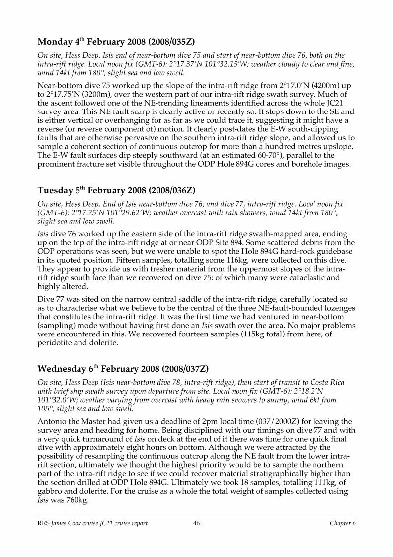
RRS James Cook cruise JC21 cruise report 46 Chapter 6
Monday 4th February 2008 (2008/035Z)On site, Hess Deep. Isis end of near-bottom dive 75 and start of near-bottom dive 76, both on theintra-rift ridge. Local noon fix (GMT-6): 2°17.37’N 101°32.15’W; weather cloudy to clear and fine,wind 14kt from 180°, slight sea and low swell.Near-bottom dive 75 worked up the slope of the intra-rift ridge from 2°17.0’N (4200m) upto 2°17.75’N (3200m), over the western part of our intra-rift ridge swath survey. Much ofthe ascent followed one of the NE-trending lineaments identified across the whole JC21survey area. This NE fault scarp is clearly active or recently so. It steps down to the SE andis either vertical or overhanging for as far as we could trace it, suggesting it might have areverse (or reverse component of) motion. It clearly post-dates the E-W south-dippingfaults that are otherwise pervasive on the southern intra-rift ridge slope, and allowed us tosample a coherent section of continuous outcrop for more than a hundred metres upslope.The E-W fault surfaces dip steeply southward (at an estimated 60-70°), parallel to theprominent fracture set visible throughout the ODP Hole 894G cores and borehole images.
Tuesday 5th February 2008 (2008/036Z)On site, Hess Deep. End of Isis near-bottom dive 76, and dive 77, intra-rift ridge. Local noon fix(GMT-6): 2°17.25’N 101°29.62’W; weather overcast with rain showers, wind 14kt from 180°,slight sea and low swell.Isis dive 76 worked up the eastern side of the intra-rift ridge swath-mapped area, endingup on the top of the intra-rift ridge at or near ODP Site 894. Some scattered debris from theODP operations was seen, but we were unable to spot the Hole 894G hard-rock guidebasein its quoted position. Fifteen samples, totalling some 116kg, were collected on this dive.They appear to provide us with fresher material from the uppermost slopes of the intra-rift ridge south face than we recovered on dive 75: of which many were cataclastic andhighly altered.Dive 77 was sited on the narrow central saddle of the intra-rift ridge, carefully located soas to characterise what we believe to be the central of the three NE-fault-bounded lozengesthat constitutes the intra-rift ridge. It was the first time we had ventured in near-bottom(sampling) mode without having first done an Isis swath over the area. No major problemswere encountered in this. We recovered fourteen samples (115kg total) from here, ofperidotite and dolerite.
Wednesday 6th February 2008 (2008/037Z)On site, Hess Deep (Isis near-bottom dive 78, intra-rift ridge), then start of transit to Costa Ricawith brief ship swath survey upon departure from site. Local noon fix (GMT-6): 2°18.2’N101°32.0’W; weather varying from overcast with heavy rain showers to sunny, wind 6kt from105°, slight sea and low swell.Antonio the Master had given us a deadline of 2pm local time (037/2000Z) for leaving thesurvey area and heading for home. Being disciplined with our timings on dive 77 and witha very quick turnaround of Isis on deck at the end of it there was time for one quick finaldive with approximately eight hours on bottom. Although we were attracted by thepossibility of resampling the continuous outcrop along the NE fault from the lower intra-rift section, ultimately we thought the highest priority would be to sample the northernpart of the intra-rift ridge to see if we could recover material stratigraphically higher thanthe section drilled at ODP Hole 894G. Ultimately we took 18 samples, totalling 111kg, ofgabbro and dolerite. For the cruise as a whole the total weight of samples collected usingIsis was 760kg.

RRS James Cook cruise JC21 cruise report 47 Chapter 6
Thursday 7th February 2008 (2008/038Z)Transit to Costa Rica. Local noon fix (GMT-6): 3°56.9’N 97°21.2’W; average speed 14.5kt;distance travelled 220nm; weather overcast to clear, wind light airs, slight sea and low swell.The day was spent by the science party in working on curating and describing the divesamples, and writing and collating material for the cruise report. The formal cruise debriefmeeting chaired by the Master occupied Chris, Damon and Donna for half of the day. Inthe evening a semi-formal dinner was held for all, preceded (and, for some, followed) bydrinks in the bar. Damon viewed both sunset and sunrise from the same seat in the bar.
Friday 8th February 2008 (2008/039Z)Transit to Costa Rica. Local noon fix (GMT-6): 6°09.7’N 92°19.8’W; average speed 13.7kt;distance travelled 328nm; weather clear and fine, wind light airs, slight sea and low swell.More hard work for the science party in collating information for the cruise report andpacking up. In the evening a barbecue was held on the starboard main deck.
Saturday 9th February 2008 (2008/040Z)Transit to Costa Rica. Local noon fix (GMT-6): 8°20.6’N 87°22.1’W; average speed 13.5kt;distance travelled 324nm; weather fine and clear, wind 10kt from 050°, slight sea and low swell.Logging of the ship’s EM120 multibeam sonar was switched off in the morning as weentered Costa Rican territorial waters. Final compilation and distribution of the cruisereport; packing of crates and boxes either to be airfreighted home or left on board shipuntil its return to the UK in June. A science meeting was held in the afternoon to discusspost-cruise science plans.
Sunday 10th February 2008 (2008/041Z)Arrival in Puerto Caldera, Costa Rica, 9°55’N 84°43.8’W. End of cruise JC21.Arrival in Puerto Caldera, Gulf of Nicoya, Costa Rica. The science party disembarked byboat transfer and were taken to San José. Because the cruise was originally to have endedin Panama, everyone had flights departing from there. Those with flights early on themorning of 11th flew direct from San José on 10th, staying overnight in Panama; those withflights later on 11th stayed in San José overnight and flew on to Panama that morning.

RRS James Cook cruise JC21 cruise report 48 Chapter 7
Chapter 7. End Matter7.1 ReferencesAllerton, S., Wallis, D., Derrick, J., Smith, D. & MacLeod, C.J., New wireline seafloor drill augers well. Eos
Trans. AGU., 80 (33), 367, 1999.Ballu, V., Hildebrand, J.A. and Canuteson, E.L., 1999. The density structure associated with oceanic crustal
rifting at the Hess Deep: a seafloor and sea-surface gravity study. Earth and Planetary Science Letters,171(1): 21-34.
Blackman, D.K., Ildefonse, B., John, B.E., Ohara, Y., Miller, D.J., MacLeod, C.J., and the Expedition 304/305Scientists, 2006. Proc. IODP, 304/305: College Station TX (Integrated Ocean Drilling ProgramManagement International, Inc.). doi:10.2204/iodp.proc.304305.2006
Boudier, F., Nicolas, A. and Ildefonse, B., 1996. Magma chambers in the Oman ophiolite : fed from the top orfrom the bottom ? Earth and Planetary Science Letters, 144: 239-250.
Coogan, L.A., Gillis, K.M., MacLeod, C.J., Thompson, G.,, Hekinian, R., 2002. Petrology and geochemistry ofthe lower, ocean crust formed at the East Pacific Rise and exposed at Hess Deep: a synthesis and newresults. Geochem. Geophys. Geosyst. Special issue: The Oman ophiolite and ocean ridge processes.DOI:10.1029/2001GC000230.
Francheteau, J., Armijo, R., Cheminee, J.L., Hekinian, R., Lonsdale, P., Blum, N., 1990. 1 Ma East Pacific Riseoceanic crust and uppermost mantle exposed by rifting in Hess Deep (equatorial Pacific Ocean). EarthPlanet. Sci. Lett. 101, 281–295.
Gillis, K.M., Mével, C., Allan, J. (Eds.), 1993. Proc. ODP, Init. Repts., vol. 147. Ocean Drilling Program,College Station, TX. 366 pp.
Henstock, T.J., Woods, A.W. and White, R.S., 1993. The accretion of oceanic crust by episodic sill intrusion.Journal of Geophysical Research, 98(B3): 4143-4161.
Karson, J.A., Klein, E.M., Hurst, S.D., Lee, C.E., Rivizzigno, P.A., Curewitz, D., Morris, A.R., Miller, D.J.,Varga, R.G., Christeson, G.L., Cushman, B., O'Neill, J.M., Brophy, J.G., Gillis, K.M., Stewart, M.A. andSutton, A.L., 2002. Structure of uppermost fast-spread oceanic crust exposed at the Hess Deep Rift:Implications for subaxial processes at the East Pacific Rise. Geochemistry Geophysics Geosystems, 3.
Kelemen, P., Koga, K. and Shimizu, N., 1997. Geochemistry of gabbro sills in the crust-mantle transition zoneof the Oman ophiolite: implications for the origin of the oceanic lower crust. Earth and Planetary ScienceLetters, 146: 475-488.
Klein, E. M., Smith, D. K., Williams, C. M. and Schouten, H., 2005. Counter-rotating microplates at theGalapagos triple junction. Nature, 433: 855-858.
Lonsdale, P., 1988. Structural Pattern of the Galapagos Microplate and Evolution of the Galapagos TripleJunctions. Journal of Geophysical Research-Solid Earth and Planets, 93(B11): 13551-13574.
MacLeod, C.J. and Yaouancq, G., 2000. A fossil melt lens in the Oman ophiolite: Implications for magmachamber processes at fast spreading ridges. Earth and Planetary Science Letters, 176(3-4): 357-373.
MacLeod, C.J., Boudier, F., Yaouancq, G. and Richter, C., 1996a. gabbro fabrics from Site 894, Hess Deep :implications for magma chamber processes at the East Pacific Rise. In: C. Mével, K.M. Gillis, J.F. Allanand P.S. Meyer (Editors), Proc. ODP, Sci. Res. Ocean Drilling Program, College Station, TX,147, pp. 317-328.
MacLeod, C.J., Célérier, B., Früh-Green, G.L. and Manning, C.E., 1996b. Tectonics of Hess Deep: A synthesisof drilling results from Leg 147. In: C. Mével, K.M. Gillis, J.F. Allan and P.S. Meyer (Editors), Proc. ODP,Sci. Res. Ocean Drilling Program, College Station, TX, 147, pp. 461-475.
Phipps Morgan, J. and Chen, Y.J., 1993. The genesis of oceanic crust : magma injection, hydrothermalcirculation, and crustal flow. Journal of Geophysical Research, 98(B4): 6283-6297.
Quick, J.E. and Denlinger, R.P., 1993. Ductile deformation and the origin of layered gabbro in ophiolites.Journal of Geophysical Research, 98(B8): 14015-14027.
Sinton, J.M. and Detrick, R.S., 1992. Mid-ocean ridge magma chambers. Journal of Geophysical Research,97(B1): 197-216.
Streckheisen, A., 1974. Classification and nomenclature of plutonic rocks. Geol. Rundsch., 63: 773–786.

RRS James Cook cruise JC21 cruise report 49 Chapter 7
Wiggins, S.M., Dorman, L.R.M., Cornuelle, B.D. and Hildebrand, J.A., 1996. Hess Deep rift valley structurefrom seismic tomography. Journal of Geophysical Research - Solid Earth, 101(B10): 22335-22353.
Wilson, D.S., Teagle, D.A.H., Alt, J.C., Banerjee, N.R., Umino, S., Miyashita, S., Acton, G.D., Anma, R., Barr,S.R., Belghoul, A., Carlut, J., Christie, D.M., Coggon, R.M., Cooper, K.M., Cordier, C., Crispini, L.,Durand, S.R., Einaudi, F., Galli, L., Gao, Y.J., Geldmacher, J., Gilbert, L.A., Hayman, N.W., Herrero-Bervera, E., Hirano, N., Holter, S., Ingle, S., Jiang, S.J., Kalberkamp, U., Kerneklian, M., Koepke, J.,Laverne, C., Vasquez, H.L.L., Maclennan, J., Morgan, S., Neo, N., Nichols, H.J., Park, S.H., Reichow, M.K.,Sakuyama, T., Sano, T., Sandwell, R., Scheibner, B., Smith-Duque, C.E., Swift, S.A., Tartarotti, P., Tikku,A.A., Tominaga, M., Veloso, E.A., Yamasaki, T., Yamazaki, S. and Ziegler, C., 2006. Drilling to gabbro inintact ocean crust. Science, 312(5776): 1016-1020.
7.2 AcknowledgementsWe gratefully acknowledge funding for this cruise by the Natural Environment ResearchCouncil through the Site Survey Initiative of the UK IODP programme. We thankProfessor Sir Geoffrey Allen FRS, Professor Mike Bickle FRS, and Dr Chris Franklin andother NERC staff for their support over the years it has taken for this project to come tofruition. Colin Day of NMF SS provided much useful advice throughout the planning ofthe cruise.We owe the success of the cruise in large part to the unstinting efforts and professionalismof Captain Antonio Gatti, the officers and crew of RRS James Cook. Although nature didnot cooperate, the BGS group gave us support throughout. Dave Turner and the Isis team,from the National Oceanography Centre, Southampton, performed superbly under greatpressure for the duration of the cruise and their contribution cannot be overstated. Wethank you all.
7.3 A note on the citation of this reportThe appendices listed below contain much of the detailed, specific information collectedduring the cruise. Because this information will form the basis for the post-cruise researchof the entire academic science party, including the primary material for two PhDstudentships, we consider this to be proprietary for the duration of the project.Accordingly, we do not distribute the appendices with the cruise report except to the JC21scientific party. Any enquiries or requests in this regard should be directed to the PrincipalScientist, Dr. Chris MacLeod, at Cardiff University ([email protected]).For the same reason, this cruise report should be cited only in the context of its operationsrather than for academic purposes, except with the express permission of the PrincipalScientist. In such cases it should be cited as follows:MacLeod, C.J., Teagle, D.A.H., Gillis, K.M., Cazenave, P.W., Hansen, H.E., Harris, M.,Hurst, S.D., Ildefonse, B., Lissenberg, C.J., Morris, A., Shillington, D.J. & Tominaga, M.,2008. Accretion of the lower oceanic crust at fast-spreading ridges: a rock drill and near-bottomseafloor survey in support of IODP drilling in Hess Deep. RRS James Cook JC21 Cruise Report,Cardiff University, 50pp.
7.4 List of AppendicesA01_Science_operations_logAn Excel workbook containing the watchkeepers science operations log for JC21A02_Magnetometer_operationsProvides a technical description of the acquisition and processing of near-bottommagnetometer data during Isis operations

RRS James Cook cruise JC21 cruise report 50 Chapter 7
A03_Swath_bathymetryContains descriptions of the acquisition and processing of ship-mounted EM120 and Isis-mounted MS2000 swath bathymetry data, and associated issues. A comprehensive suite ofbathymetric images are provided, both at the regional scale (EM120 operations) anddetailed scale (MS2000 operations). Also includes Fledermaus scenes derived from thebathymetric data collected during JC21, and Illustrator files containing bathymetric andsample location data arranged in layers.A04_Isis_dive_navigation_dataA suite of contoured bathymetry maps showing the Isis dive tracks, together with datafiles of timestamped positions and depths for each dive.A05_ISIS_Event_Log&ImagesContains an Excel workbook of the event log for the Isis dives, updated to includetimestamped information on image acquisition, together with folders of digital still imagescaptured during dive operations.A06_Ship+Drill+ROV_System_reportsA series of documents provided by the Isis ROV and BRIDGE drill teams containingrelevant technical information on the ship, Isis and BRIDGE drill systems.A07_Sample_Location_ImagesContains digital imagery of the Isis ROV and BRIDGE drill sampling sites.A08_Sample_log_sheetsSummary PDF documents describing the samples collected during JC21.A09_Petrology_summariesContains Excel workbooks containing shipboard petrological data for the JC21 samplecollection.A10_Sample_PhotographsProvides digital still images of all sample collected during JC21, including photographs ofcut surfaces.