Embed Size (px)
Citation preview
Crush Performance of Thin Walled
Spot-Welded and
Weld-Bonded Sections
w w w . a u t o s t e e l . o r g
Weld-Bonded Sections
Paul Davidson*, M.S Engineering
Prof. Donald Malen
University of Michigan, Ann Arbor, MI – 48109

Acknowledgement
This project was sponsored by the Weld Bond Project Team of the
Auto Steel Partnership
w w w . a u t o s t e e l . o r g
Auto Steel Partnership

Objective
• Determine influence of weld
pitch and adhesive on axial
load deflection characteristics
of a hexagonal thin walled
section.
w w w . a u t o s t e e l . o r g

Expected results
• Adhesive improves stability and average crush force for thin metals.
• Adhesive has little effect on thicker, more stable sections.
• Adhesive is more effective for greater spot
w w w . a u t o s t e e l . o r g
• Adhesive is more effective for greater spot weld spacing.

Model Geometry
Rigid Mass
Impacting velocity
- Hex Section column was considered for this drop test simulation. - A 400mm tall column axial impact-loaded with rigid mass of 139kg and 11.15m/s velocity.- Adhesive with uniform thickness of 0.66mm was considered.- Simulation was conducted using LSDYNA® Explicit code.
w w w . a u t o s t e e l . o r g
Impacting velocity

Adhesive Modeling
1. Gurson shell model
2. Gurson solid model
Metal Mid Plane
Metal Mid PlaneAdhesive Mid Plane
• Two modeling methods and 5 Adhesive models benchmarked with physical test.• Gurson shell model was selected for this study.
Shell Model
Physical section
Continuum model
w w w . a u t o s t e e l . o r g
1. Arup solid model
2. Johnson-Cook solid model
Solid Model
Tie Break Contact
Cohesive model

Work Breakdown
Between spot weld buckling
Without adhesive
Planar
flange
Imperfect
flange
With adhesive
Planar
flange
Imperfect
flange
w w w . a u t o s t e e l . o r g
Thickness
(mm)
Pitch (mm)
0.7
2.2
10020 60
1.5
HSLA 350Thickness
(mm)
Pitch (mm)
0.7
2.2
10020 60
1.5
DP 590
IHS140 DP 980
Thickness
(mm)
Pitch (mm)
0.7
2.2
10020 60
1.5
HSLA 350Thickness
(mm)
Pitch (mm)
0.7
2.2
10020 60
1.5
DP 590
IHS140 DP 980Thickness
(mm)
Pitch (mm )
0.7
2.2
10020 60
1.5Thickness
(mm)
Pitch (mm )
0.7
2.2
10020 60
1.5Thickness
(mm)
Pitch (mm )
0.7
2.2
10020 60
1.5Thickness
(mm)
Pitch (mm )
0.7
2.2
10020 60
1.5

Responses
• Response reported are:‒ Fmax – Maximum load.‒ - Average force taken over the entire displacement.‒ Energy absorbed is given by
Fatotal
Fmax
Cripple event
Crush event
w w w . a u t o s t e e l . o r g
Fatotal
0 25 255 Dmax
Forc
e
Displacement (mm)

Data Analysis
Pitch [m
m]
High strength –High thickness
High strength –Low thicknessLow strength –
Low thickness
Low strength –
w w w . a u t o s t e e l . o r g
• Comparison of behavior at the extreme parameters of design.• DP890 and IF140 were characterized with strain rate sensitivity.
Pitch [m
m]
Low strength –High thickness

IF140 No Adhesive
Fmax Fatotal Dmax
10.6 2.53 357.59
Fmax Fatotal Dmax
10.6 2.53 356.5
Fmax Fatotal Dmax
10.6 2.53 357.7
Fmax Fatotal Dmax
25.4 8.09 107.4
Fmax Fatotal Dmax
25.4 7.43 117.1
Fmax Fatotal Dmax
25.5 8.02 108.4
p = 20mm 60mm 100mm
0.7
mm
1.5
mm
w w w . a u t o s t e e l . o r g
25.4 8.09 107.4 25.4 7.43 117.1 25.5 8.02 108.4
Fmax Fatotal Dmax
39.1 15.4 56.01
Fmax Fatotal Dmax
39.0 15.2 56.74
Fmax Fatotal Dmax
39.1 12.8 67.31
1.5
mm
t =
2.2
mm
All forces in x104N
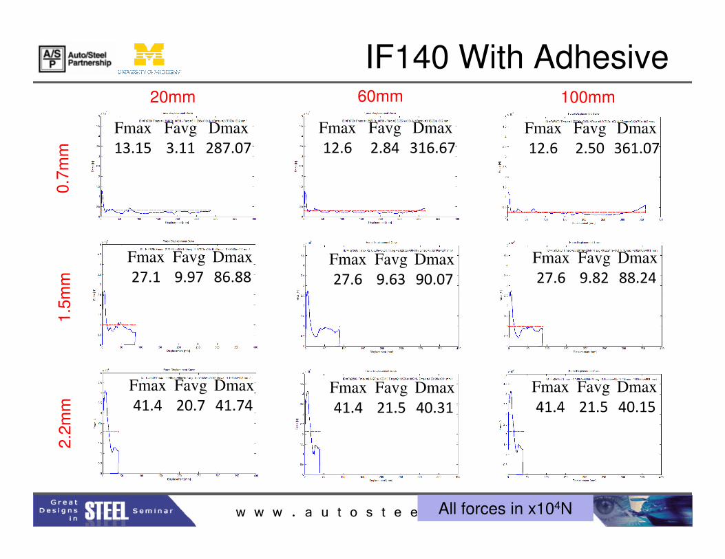
IF140 With Adhesive
Fmax Favg Dmax
13.15 3.11 287.07
Fmax Favg Dmax
12.6 2.84 316.67
Fmax Favg Dmax
12.6 2.50 361.07
Fmax Favg Dmax
27.1 9.97 86.88Fmax Favg Dmax
27.6 9.63 90.07
Fmax Favg Dmax
27.6 9.82 88.24
20mm 60mm 100mm
0.7
mm
1.5
mm
w w w . a u t o s t e e l . o r g
27.1 9.97 86.88 27.6 9.63 90.07 27.6 9.82 88.24
Fmax Favg Dmax
41.4 20.7 41.74
Fmax Favg Dmax
41.4 21.5 40.31
Fmax Favg Dmax
41.4 21.5 40.15
1.5
mm
2.2
mm
All forces in x104N

Qualitative Observations
IF140 p=100mm, t=2.2mm
Pitch [m
m]
w w w . a u t o s t e e l . o r g
Pitch [m
m]

AdhesiveNo Adhesive
IF140 p=100mm, t=2.2mm
time=0.002sec
Cripple Event
Puckering No
w w w . a u t o s t e e l . o r g
Expected difference in flange buckling mode
Puckering No
Puckering

IF140 p=100mm, t=2.2mm
No adhesive case: interweld
buckling initiates crush mode with
low average force level
350,000
400,000
450,000
No adhesive Adhesive
Crush Event
w w w . a u t o s t e e l . o r g
0
50,000
100,000
150,000
200,000
250,000
300,000
350,000
0 0.02 0.04 0.06 0.08
time=0.010s
Deformation (m)
Fo
rce
(N
)no adhesive
with adhesive

Qualitative Observations
IF140 p=100mm, t=0.7mm
Pitch [m
m]
w w w . a u t o s t e e l . o r g
Pitch [m
m]
AdhesiveNo Adhesive
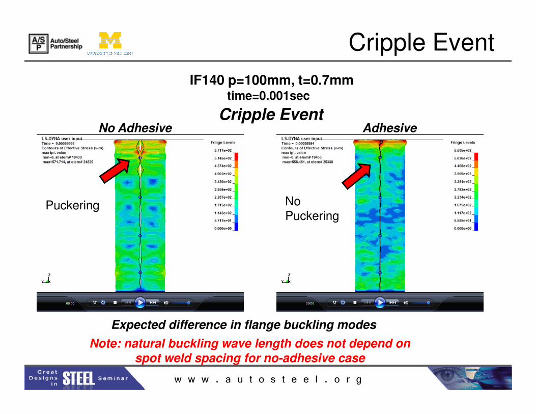
IF140 p=100mm, t=0.7mmtime=0.001sec
Cripple Event
Cripple Event
Puckering No
w w w . a u t o s t e e l . o r g
Expected difference in flange buckling modes
Note: natural buckling wave length does not depend on spot weld spacing for no-adhesive case
Puckering No
Puckering

No adhesive
Adhesive
No adhesive case: Expected
flange buckling mode
-Flange folding.
-Euler buckling of corner
IFS140. t=0.7mm, p=100mm
Crush Event
w w w . a u t o s t e e l . o r g
time=0.016s
0
20,000
40,000
60,000
80,000
100,000
120,000
140,000
0.00 0.10 0.20 0.30 0.40Deformation (m)
Fo
rce
(N
)
no adhesive
with adhesive

Ivv
v
v
v
v
Flange Foldingv
v
w w w . a u t o s t e e l . o r g
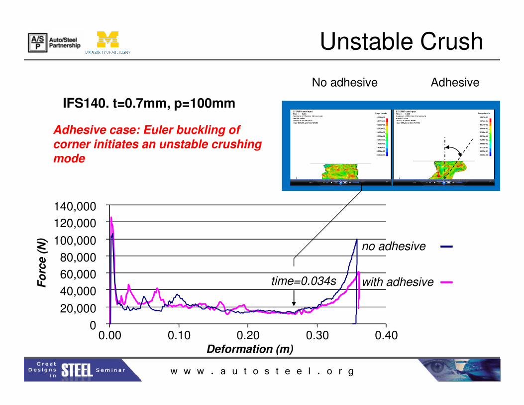
Adhesive case: Euler buckling of
corner initiates an unstable crushing mode
IFS140. t=0.7mm, p=100mm
140,000
No adhesive Adhesive
Unstable Crush
w w w . a u t o s t e e l . o r g
time=0.034s
0
20,000
40,000
60,000
80,000
100,000
120,000
140,000
0.00 0.10 0.20 0.30 0.40Deformation (m)
Fo
rce
(N
)
no adhesive
with adhesive

Qualitative Observations
DP980 p=100mm, t=2.2mm
Pitch [m
m]
w w w . a u t o s t e e l . o r g
Pitch [m
m]

DP980 p=100mm, t=2.2mm
time=0.004s
For this impact energy level, corner crippling dominates average force level
No adhesive Adhesive
no adhesive with adhesive
Crush Event
w w w . a u t o s t e e l . o r g
time=0.004s
0
200,000
400,000
600,000
800,000
1,000,000
0 0.005 0.010 0.015 0.020 0.025
Fo
rce (
N)
Deformation (m)
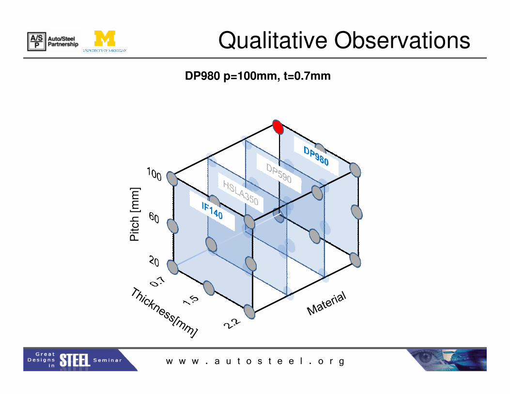
Qualitative Observations
DP980 p=100mm, t=0.7mm
Pitch [m
m]
w w w . a u t o s t e e l . o r g
Pitch [m
m]

DP980, t=0.70mm, p=100mm
300,000
350,000
Fo
rce (
N)
No adhesive Adhesive
Adhesive case: corner initiates an unstable crushing mode
Crush Event
w w w . a u t o s t e e l . o r g
0
50,000
100,000
150,000
200,000
250,000
300,000
0.00 0.05 0.10 0.15 0.20
Fo
rce (
N)
Deformation (m)
time=0.015sno adhesive
with adhesive

Expected v.s Observed
• Adhesive improves
stability and average
crush force for thin
metals.
• Adhesive has little
• Adhesive lowers
stability and average
crush force for thin
metals.
• Adhesive increases
EXPECTED OBSERVED
w w w . a u t o s t e e l . o r g
• Adhesive has little
effect on thicker, more
stable sections.
• Adhesive is more
effective for greater
spot weld spacing.
• Adhesive increases
average crush force for
thicker sections.
• Adhesive is not
always more effective
for greater spot weld
spacing.
Favg: DP980
20mm
60mm
100mm
1.5mm 2.2mm
Pe
rce
nta
ge
Im
pro
ve
me
nt
[%]
0
20
40
60
80
100
SW
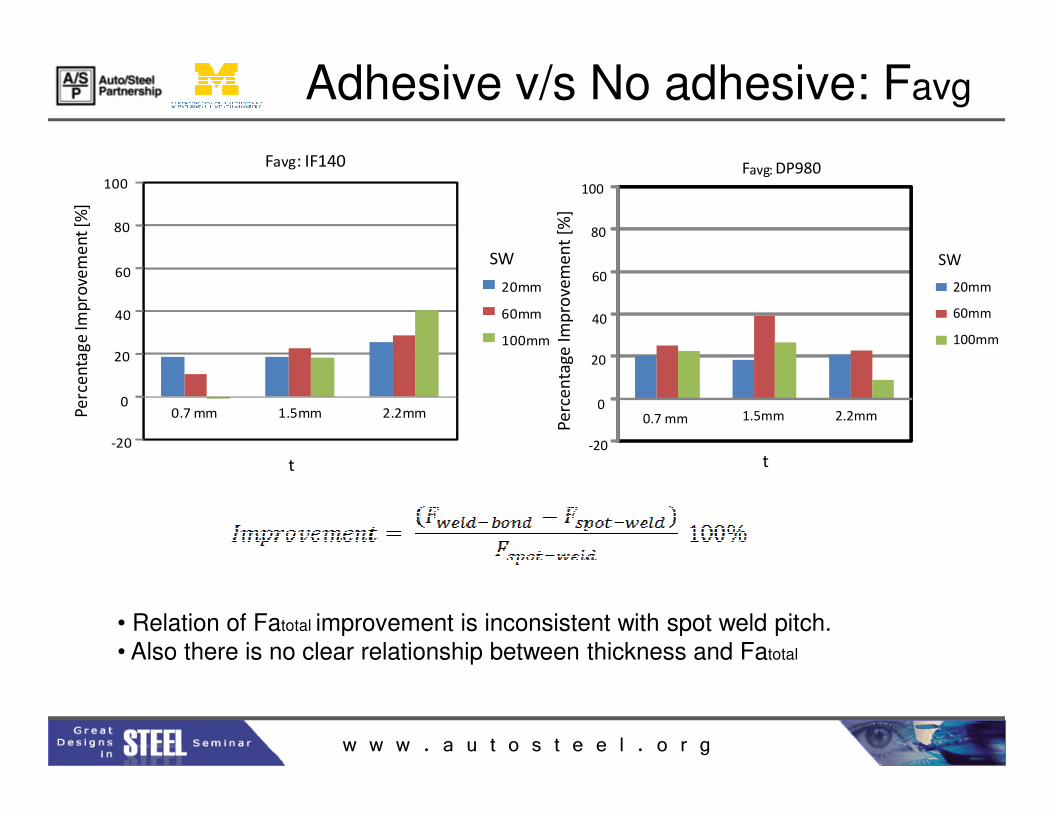
Adhesive v/s No adhesive: Favg
0
20
40
60
80
100
0.7 mm 1.5mm 2.2mm
Favg: IF140
20mm
60mm
100mm
Pe
rce
nta
ge
Imp
rove
me
nt
[%]
SW
w w w . a u t o s t e e l . o r g
0.7 mm 1.5mm 2.2mm
Pe
rce
nta
ge
Im
pro
ve
me
nt
[%]
-20
0
t
• Relation of Fatotal improvement is inconsistent with spot weld pitch.• Also there is no clear relationship between thickness and Fatotal
-20
00.7 mm 1.5mm 2.2mmP
erc
en
tag
e Im
pro
vem
en
t [%
]
t

Adhesive v/s No adhesive: Fmax
0
20
40
60
Pe
rce
nta
ge
Im
pro
ve
me
nt
[%]
0.7mm
1.5mm
2.2mm
Fmax: IF140
80
100
20mm
60mm
100mm
SW
Pe
rce
nta
ge
Imp
rove
me
nt
[%]
20mm
60mm
100mm
DP890
0
20
40
60
80
100
SW
Fmax: DP590Fmax: DP980
w w w . a u t o s t e e l . o r g
IF140 shows expected increase in Fmax at low thicknesses.
-20
0
0.7 1.5 2.2
Pe
rce
nta
ge
t
Pe
rce
nta
ge
Imp
rove
me
nt
[%]
-20
0
0.7 1.5 2.2
t

Work done
-20
0
20
40
60
80
100
0.7 mm 1.5mm 2.2mm
Favg: IF140
20mm
60mm
100mm
Pe
rce
nta
ge
Im
pro
ve
me
nt
[%]
t
SW
MODELING SIMULATIONS RESULTS
w w w . a u t o s t e e l . o r g
0.00E+00
5.00E+04
1.00E+05
1.50E+05
2.00E+05
2.50E+05
3.00E+05
3.50E+05
4.00E+05
4.50E+05
5.00E+05
0.00 1.00 2.00 3.00 4.00 5.00 6.00 7.00
Fa
vg
[N]
�p
----- : With adhesive
___ : No adhesive
DP980
HSLA350
IF140
2.2mm
1.5mm
0.7mm
σcr-p>σy σcr-p<σy
DP590
F
?
0m
m
~25m
m
>100mm
peak
Axial deformation
Axial force
Thick walled section
Thin walled section
ANALYSISCALCULATIONCORRELATION

• For the fixed energy level used in this DOE (mv2/2), the mean crush force for the thicker and higher strength conditions was dominated by corner crippling behavior
•Spot weld pitch does not have a strong, consistent influence on mean crush force improvement with adhesive
•Plate slenderness is an important indicator for mean crush force. The
Conclusion
w w w . a u t o s t e e l . o r g
•Plate slenderness is an important indicator for mean crush force. The benefit of adhesive bonding is greater for less slender plates (β small)
•An adhesive bonded flange can precipitate an unstable crush mode particularly for sections with slender plates
•Before extending the DOE, it is necessary to understand progressive buckling behavior of the structure (see suggestions for Future Work)

• Theoretical study of:• Buckling Modes• Progression during crush
• Sensitivity study (Robustness)• Pillowing• Imperfection: flange angle, section shape, etc• Strain rate• Crush initiator presence and type
Future work
w w w . a u t o s t e e l . o r g
• Crush initiator presence and type

Thank You!
w w w . a u t o s t e e l . o r g
Thank You!