Embed Size (px)
Citation preview
Crutch Tip for Swing-through Crutch WalkingControl Based on a Kinetic Shape
Daniel Capecci�, Seok Hun Kim†, Kyle B. Reed�, Ismet Handzic��Department of Mechanical Engineering | †School of Physical Therapy & Rehabilitation Sciences
University of South Florida
Tampa, Florida 33620
Email: [email protected], [email protected], [email protected], [email protected]
Abstract—This paper illustrates the dynamic effects of usinga kinetic shape as a crutch tip on swing through crutchwalking (non-weight bearing). The overground crutch walkingof four participants was measured to examine the effect of aKinetic Crutch Tip (KCT) on step length and swing time usinga ProtoKinetics R©Zeno Walkway System. Changes in groundreaction forces during the crutch gait cycle were examined byhaving the participants walk on an instrumented treadmill. Wequantify changes in crutch dynamics by comparing results tostandard rubber point tip crutch walking. The results showedthat introducing a KCT to crutch walking can alter steplength and swing time asymmetries during overground walking.Participants walking with a forward forcing KCT experienceda reduction in the horizontal ground reaction forces of up to74% compared to walking on standard rubber crutch tips. Thebackward forcing KCT reduced the heel strike peak forces byas much as 27%. These findings show that crutch walkingdynamics can be customized and optimized to yield a specificcrutch walking behavior tailored to various user needs orwalking environments.
I. INTRODUCTION
The majority of current crutch design variations focuson the user interaction to increase comfort and decreaseupper-limb support stress. Much less effort has been spenton finer control of crutch dynamics caused by crutch-groundinteractions during use. While upper-limb support comfortis a significant aspect in crutch design, it is an incompletepicture without considering the behavior at the crutch-groundinterface. By looking at this often overlooked interaction,we are examining the possibility of changing the crutch tipshape in order to systematically manipulate crutch walkingdynamics. Having customizable crutch dynamics may makeit possible to solve the issues of comfort and efficiency whileaiding in the rehabilitation of crutch users. For instance, ifa crutch user suffers from plantar faciitis [1] and needs tolimit overexertion of poor bio-mechanics, a Kinetic CrutchTip (KCT) may be configured to reduce impact forcesexperienced at heel strike. The force changes at the crutch-ground interface are directly related to stresses experiencedby the user’s wrist, elbow, and shoulder. Therefore, anyability to manipulate crutch-ground reaction forces wouldallow for the systematic reduction of these stresses.
To accomplish this optimization of forces, a kineticshape [2] using a non-constant radius crutch tip can be usedto systematically change the user’s dynamics. Since a non-constant radius wheel can redirect an applied user’s weightinto a rolling force [3], a similar shape applied to the tip
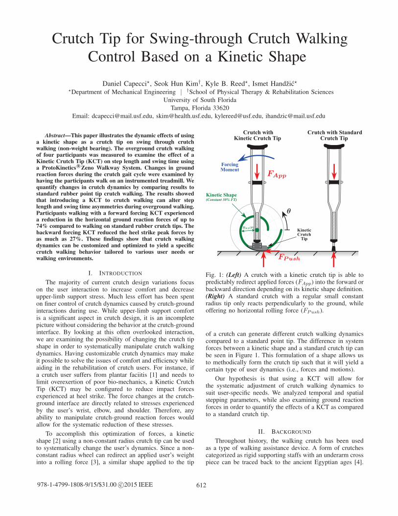
Fig. 1: (Left) A crutch with a kinetic crutch tip is able topredictably redirect applied forces (FApp) into the forward orbackward direction depending on its kinetic shape definition.(Right) A standard crutch with a regular small constantradius tip only reacts perpendicularly to the ground, whileoffering no horizontal rolling force (FPush).
of a crutch can generate different crutch walking dynamicscompared to a standard point tip. The difference in systemforces between a kinetic shape and a standard crutch tip canbe seen in Figure 1. This formulation of a shape allows usto methodically form the crutch tip such that it will yield acertain type of user dynamics (i.e., forces and motions).
Our hypothesis is that using a KCT will allow forthe systematic adjustment of crutch walking dynamics tosuit user-specific needs. We analyzed temporal and spatialstepping parameters, while also examining ground reactionforces in order to quantify the effects of a KCT as comparedto a standard crutch tip.
II. BACKGROUND
Throughout history, the walking crutch has been usedas a type of walking assistance device. A form of crutchescategorized as rigid supporting staffs with an underarm crosspiece can be traced back to the ancient Egyptian ages [4].
612978-1-4799-1808-9/15/$31.00 c©2015 IEEE
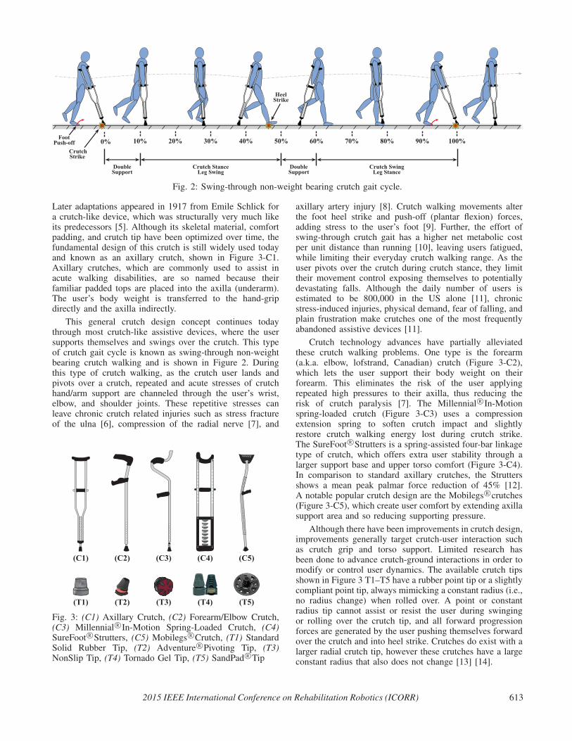
Fig. 2: Swing-through non-weight bearing crutch gait cycle.
Later adaptations appeared in 1917 from Emile Schlick fora crutch-like device, which was structurally very much likeits predecessors [5]. Although its skeletal material, comfortpadding, and crutch tip have been optimized over time, thefundamental design of this crutch is still widely used todayand known as an axillary crutch, shown in Figure 3-C1.Axillary crutches, which are commonly used to assist inacute walking disabilities, are so named because theirfamiliar padded tops are placed into the axilla (underarm).The user’s body weight is transferred to the hand-gripdirectly and the axilla indirectly.
This general crutch design concept continues todaythrough most crutch-like assistive devices, where the usersupports themselves and swings over the crutch. This typeof crutch gait cycle is known as swing-through non-weightbearing crutch walking and is shown in Figure 2. Duringthis type of crutch walking, as the crutch user lands andpivots over a crutch, repeated and acute stresses of crutchhand/arm support are channeled through the user’s wrist,elbow, and shoulder joints. These repetitive stresses canleave chronic crutch related injuries such as stress fractureof the ulna [6], compression of the radial nerve [7], and
Fig. 3: (C1) Axillary Crutch, (C2) Forearm/Elbow Crutch,(C3) Millennial R©In-Motion Spring-Loaded Crutch, (C4)SureFoot R©Strutters, (C5) Mobilegs R©Crutch, (T1) StandardSolid Rubber Tip, (T2) Adventure R©Pivoting Tip, (T3)NonSlip Tip, (T4) Tornado Gel Tip, (T5) SandPad R©Tip
axillary artery injury [8]. Crutch walking movements alterthe foot heel strike and push-off (plantar flexion) forces,adding stress to the user’s foot [9]. Further, the effort ofswing-through crutch gait has a higher net metabolic costper unit distance than running [10], leaving users fatigued,while limiting their everyday crutch walking range. As theuser pivots over the crutch during crutch stance, they limittheir movement control exposing themselves to potentiallydevastating falls. Although the daily number of users isestimated to be 800,000 in the US alone [11], chronicstress-induced injuries, physical demand, fear of falling, andplain frustration make crutches one of the most frequentlyabandoned assistive devices [11].
Crutch technology advances have partially alleviatedthese crutch walking problems. One type is the forearm(a.k.a. elbow, lofstrand, Canadian) crutch (Figure 3-C2),which lets the user support their body weight on theirforearm. This eliminates the risk of the user applyingrepeated high pressures to their axilla, thus reducing therisk of crutch paralysis [7]. The Millennial R©In-Motionspring-loaded crutch (Figure 3-C3) uses a compressionextension spring to soften crutch impact and slightlyrestore crutch walking energy lost during crutch strike.The SureFoot R©Strutters is a spring-assisted four-bar linkagetype of crutch, which offers extra user stability through alarger support base and upper torso comfort (Figure 3-C4).In comparison to standard axillary crutches, the Struttersshows a mean peak palmar force reduction of 45% [12].A notable popular crutch design are the Mobilegs R©crutches(Figure 3-C5), which create user comfort by extending axillasupport area and so reducing supporting pressure.
Although there have been improvements in crutch design,improvements generally target crutch-user interaction suchas crutch grip and torso support. Limited research hasbeen done to advance crutch-ground interactions in order tomodify or control user dynamics. The available crutch tipsshown in Figure 3 T1–T5 have a rubber point tip or a slightlycompliant point tip, always mimicking a constant radius (i.e.,no radius change) when rolled over. A point or constantradius tip cannot assist or resist the user during swingingor rolling over the crutch tip, and all forward progressionforces are generated by the user pushing themselves forwardover the crutch and into heel strike. Crutches do exist with alarger radial crutch tip, however these crutches have a largeconstant radius that also does not change [13] [14].
2015 IEEE International Conference on Rehabilitation Robotics (ICORR) 613
Crutch users include chronically disabled individualsthat rely on their crutches for everyday ambulation. Thisgroup includes disabilities such as lower limb amputation,spinal bifeda, cerebral palsy, muscular dystrophy, spinalcord injury, post-polio syndrome, osteoarthritis, or multiplesclerosis. Crutch users also include temporarily-injuredindividuals with acute conditions such as foot and legfractures, tendon tears, hip and knee replacements, or otherlower extremity injuries. While temporary crutch users mayheavily rely on crutches for standard non-weight bearingmobility, partial weight bearing (PWB) mobility may alsobe achieved. It has been known that systematic PWB duringthe recovery period following foot and leg injuries orsurgeries increases rehabilitative effects, speeding up therate of recovery, and decreasing recurring injury [15] [16].Compared to walkers and canes, crutch users have beenfound to achieve a target PWB on a limb twice as accurately,making them a highly effective tool for PWB therapy [16].It would be very desirable to be able to manipulate thecrutch-ground forces during crutch stance and in turn thecrutch user’s dynamics such that it produces movementsand forces that correspond to a specifically targeted mode ofambulation and PWB. Thys et al. [17] states: “If the dynamicbehavior of crutches could be improved, it would greatlyenhance their utility and could lead to improved rehab forlocomotion deficient persons.” This study investigates howthe interaction between the crutch tip and ground affects thebehavior of crutch walking dynamics.
III. KINETIC SHAPE CRUTCH TIP DESIGN AND
FABRICATION
The formulation of the kinetic shape allows a physicalcurve to be generated that produces a known over-groundhorizontal rolling force as a vertical force is applied [2].Essentially, it uses the idea that irregularly shaped objectstend to roll towards a shrinking radius just as a circular shapewould roll down an incline. This concept has been used on agait correcting shoe [3] [18], a musical instrument [19], butcan generally be used in any mechanical situation requiringa known and exact force application that is dependenton a position. The two-dimensional kinetic shape equationin polar coordinates is described in (1); see [2] for thederivation.
R(θ) = R(θi) exp
[∫Fr(θ)
Fv(θ)dθ
]Fr(θ) < Fv(θ) (1)
where θ is the angular position around the kinetic shapeorigin, R(θi) is the initial radius of the kinetic shape,Fr(θ) is the desired horizontal ground reaction forcefunction around the shape, and Fv(θ) is the force functionvertically applied onto the center of the shape (R(θ)= 0 andperpendicular to the ground). Note that the behavior of thekinetic shape stays invariant as the shape is scaled up ordown and is only dependent on the force ratio Fr(θ)/Fv(θ).
Placing a properly defined kinetic shape on the bottomof a crutch can generate a customizable rolling effect basedon the vertical force applied by the user’s weight, Fv(θ),and the customizable horizontal force, Fr(θ), yielding thedefinition of the kinetic shape crutch tip, R(θ).
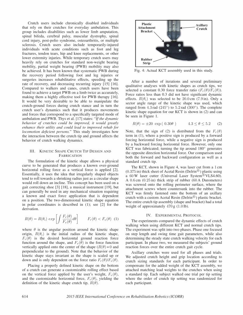
Fig. 4: Actual KCT assembly used in this study.
After a number of iterations and several preliminaryqualitative analyses with kinetic shapes as crutch tips, weselected a constant 0.30 force transfer ratio (Fr(θ)/Fv(θ)).Force ratios less than 0.3 did not have significant dynamiceffects. R(θi) was selected to be 20.0 cm (7.9 in). Only asector angle range of the kinetic shape was used, whichranged from 4.3 rad (245◦) to 5.2 rad (300◦). The completekinetic shape equation for our KCT is shown in (2) and canbe seen in Figure 1.
R(θ) = ±20 exp ( 0.30θ ) 4.3 ≤ θ ≤ 5.2 (2)
Note, that the sign of (2) is distributed from the Fr(θ)term in (1), where a positive sign is produced by a forwardforcing horizontal force, while a negative sign is producedby a backward forcing horizontal force. However, only oneKCT was fabricated; turning the tip around 180◦ generatesthe opposite direction horizontal force. Our comparison usedboth the forward and backward configuration as well as astandard crutch tip.
The KCT, shown in Figure 4, was laser cut from a 1 cm(0.375 in) thick sheet of Acetal Resin (Delrin R©) plastic usinga 60W laser cutter (Universal Laser System R©VLS4.60).A 0.6 cm (0.25 in) thick strip of rubber (60A Durometers)was screwed onto the rolling perimeter surface, where theattachment screws where countersunk into the rubber. TheKCT was firmly fastened onto the bottom of an axillarycrutch with a custom Acetal Resin (Delrin R©) plastic bracket.The entire crutch tip assembly (shape and bracket) had a totalweight of approximately 470 g (1.0 lb).
IV. EXPERIMENTAL PROTOCOL
The experiments compared the dynamic effects of crutchwalking when using different KCT and normal crutch tips.The experiment was split into two phases. Phase one focusedon step length and swing time gait parameters, while alsodetermining the steady state crutch walking velocity for eachparticipant. In phase two, we measured the subjects’ groundreaction forces over the entire crutch gait cycle.
Axillary crutches were used for all phases and trials.We adjusted crutch height and grip location according tocrutch sizing standards for each participant. In order tocompensate for the added weight of the KCT assembly, weattached matching lead weights to the crutches when usinga standard tip. Each subject walked one trial per tip settingwhere the order of crutch tip setting was randomized foreach participant.
614 2015 IEEE International Conference on Rehabilitation Robotics (ICORR)
A. SubjectsFour healthy male subjects, ages 24.25 ± 1.7, with
minimal to no crutch experience were included in this study.All subjects did not have any inherent gait or lower limbgait asymmetries and all wore non-constricting clothingwith comfortable athletic shoes. Written informed consentwas obtained from each subject prior to participation witha protocol approved by the Western Institutional ReviewBoard.
B. Phase 1: Overground Crutch WalkingWe measured stride velocity, step length, and swing time
for each participant using the ProtoKinetics R©Zeno WalkwaySystem (ProtoKinetics, LLC, Havertown, PA), which isa 2.0 ft (0.6m) by 16.0 ft (4.9m) walkway consisting ofpressure sensors that are able to accurately monitor each stepposition. We define foot step length as the distance betweenthe point where the crutches first touch down to the locationwhere the foot first touch down. Crutch step length is definedthe same way, but between the feet and crutch locations.Swing time is the time interval during which either the footor crutch are off the ground during a step.
Each participant was instructed to crutch walk for fiveminutes at a self-selected velocity over the Zeno Walkway.The participants walked back and forth over the ZenoWalkway using a normal tip, a forward forcing KCT, anda backward forcing KCT. Participants turned (180◦) at adistance of approximately two strides before and after themat to ensure steady state walking measurements. Whenturning, participants turned an approximately 0.5m radiushalf-circle. Before each trial, the participant rested until theirresting heart rate was achieved. During each five minute trial,the participant’s continuous heart rate was recorded using aBluetooth 4.0 Wahoo R©TICKR heart rate monitor controlled
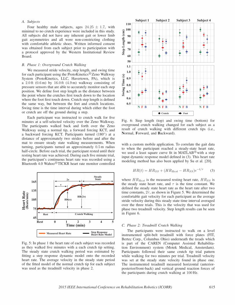
Fig. 5: In phase 1 the heart rate of each subject was recordedas they walked five minutes with a each crutch tip setting.The steady state crutch walking period was estimated byfitting a step response dynamic model onto the recordedheart rate. The average velocity in the steady state periodof the fitted model of the normal crutch tip for each subjectwas used as the treadmill velocity in phase 2.
Fig. 6: Step length (top) and swing time (bottom) foroverground crutch walking changed for each subject as aresult of crutch walking with different crutch tips (i.e.,Normal, Forward, and Backward).
with a custom mobile application. To correlate the gait datato when the participant reached a steady-state heart rate,we used a least square curve fit in MATLAB R©with a stepinput dynamic response model defined in (3). This heart ratemodeling method has also been applied by Su et al. [20].
HR(t) = HRSS + (HRRest −HRSS)e−t/τ (3)
where HRRest is the measured resting heart rate, HRSS isthe steady state heart rate, and τ is the time constant. Wedefined the steady state heart rate as the heart rate after twotime constants, 2τ , as shown in Figure 5. We determined thecomfortable gait velocity for each participant as the averagestride velocity during this steady state time interval averagedover the three trials. This is the velocity that was used forphase two treadmill velocity. Step length results can be seenin Figure 6.
C. Phase 2: Treadmill Crutch WalkingThe participants were instructed to walk on a level
instrumented split-belt treadmill with force plates (FIT,Bertec Corp., Columbus Ohio) underneath the treads whichis part of the CAREN (Computer Assisted Rehabilita-tion Environment) system (Motek Medical, Amsterdam).Participants followed their same crutch tip trial patternwhile walking for two minutes per trial. Treadmill velocitywas set at the steady state velocity found in phase one.The instrumented treadmill measured horizontal (anterior-posterior/front-back) and vertical ground reaction forces ofthe participants during crutch walking at 100Hz.
2015 IEEE International Conference on Rehabilitation Robotics (ICORR) 615
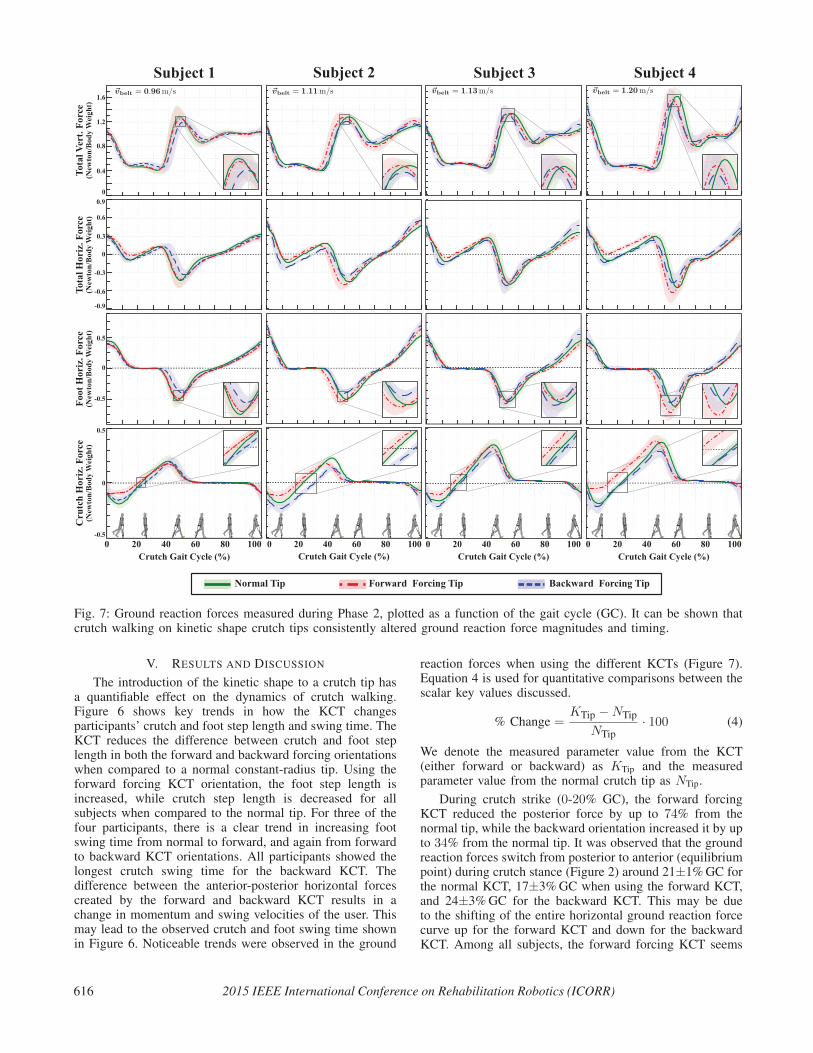
Fig. 7: Ground reaction forces measured during Phase 2, plotted as a function of the gait cycle (GC). It can be shown thatcrutch walking on kinetic shape crutch tips consistently altered ground reaction force magnitudes and timing.
V. RESULTS AND DISCUSSION
The introduction of the kinetic shape to a crutch tip hasa quantifiable effect on the dynamics of crutch walking.Figure 6 shows key trends in how the KCT changesparticipants’ crutch and foot step length and swing time. TheKCT reduces the difference between crutch and foot steplength in both the forward and backward forcing orientationswhen compared to a normal constant-radius tip. Using theforward forcing KCT orientation, the foot step length isincreased, while crutch step length is decreased for allsubjects when compared to the normal tip. For three of thefour participants, there is a clear trend in increasing footswing time from normal to forward, and again from forwardto backward KCT orientations. All participants showed thelongest crutch swing time for the backward KCT. Thedifference between the anterior-posterior horizontal forcescreated by the forward and backward KCT results in achange in momentum and swing velocities of the user. Thismay lead to the observed crutch and foot swing time shownin Figure 6. Noticeable trends were observed in the ground
reaction forces when using the different KCTs (Figure 7).Equation 4 is used for quantitative comparisons between thescalar key values discussed.
% Change =KTip −NTip
NTip· 100 (4)
We denote the measured parameter value from the KCT(either forward or backward) as KTip and the measuredparameter value from the normal crutch tip as NTip.
During crutch strike (0-20% GC), the forward forcingKCT reduced the posterior force by up to 74% from thenormal tip, while the backward orientation increased it by upto 34% from the normal tip. It was observed that the groundreaction forces switch from posterior to anterior (equilibriumpoint) during crutch stance (Figure 2) around 21±1%GC forthe normal KCT, 17±3%GC when using the forward KCT,and 24±3%GC for the backward KCT. This may be dueto the shifting of the entire horizontal ground reaction forcecurve up for the forward KCT and down for the backwardKCT. Among all subjects, the forward forcing KCT seems
616 2015 IEEE International Conference on Rehabilitation Robotics (ICORR)
to create a larger positive shift in horizontal ground reactionforces as the crutch walking velocity increases. Along withthe force magnitudes during crutch stance, this time shift ofcrutch stance equilibrium causes changes in impulse (
∫F dt)
during crutch strike and crutch push-off. The observedreduction in peak forces and impulses during crutch stanceis predicted to alleviate stresses in the user’s wrist, elbow,and shoulders [6], however joint forces were not directlymeasured in our study. During foot heel strike (40-60% GC)the forward forcing KCT increased the peak force by 15%,while the backward tip decreased the peak force by 24%both compared to the normal tip. Among all participants, thevertical heel impact force with a KCT was either equivalentor less than the impact force with a normal tip, however thecrutch walking velocity between subjects appears to affectthis peak force change.
There was no significant force profile difference betweenall tested KCTs during mid foot stance (60-85% GC). Forthree out of four participants, the horizontal foot push-offforce (85-100% GC) was increased when using the backwardKCT, indicating a slightly higher plantarflexion effort bythe user to initiate crutch stance. Although the forwardforcing KCT resulted in high crutch stance force profilemodification, we did not observe any significant changes ortrends using this crutch tip during foot stance or push-off.
Given these reported swing-through crutch dynamics, weexpect that a kinetic shape applied as a crutch tip can beconfigured to generate specific and desirable movement andforce profiles during crutch walking.
VI. CONCLUSION
We examined the temporal, spatial, and kinetic effects ofKCTs on swing through non-weight bearing crutch walking.These effects were compared to the dynamic characteristicsof normal tip crutch walking. Both KCT orientationssignificantly reduced step length. Step time was also altered,however no discernible trend was observed. It was evidentthat we were able to manipulate crutch walking gait cycleground reaction forces using a KCT. In all subjects, theforward forcing KCT created additional assistive forcesduring crutch stance, while a backward forcing KCT causedan increase in resistive forces. The changes in forces duringcrutch stance affected the subsequent leg stance phase forces.Horizontal and vertical heel strike ground reaction forceswere reduced for three out of four subjects using a backwardforcing KCT, while user foot push-off force increased forthree out of four subjects.
These results indicate that a KCT may be configuredto create desirable variations in crutch walking dynamics.We plan to further investigate KCTs with gait cyclespecific curvatures in mind. Although these initial results arepromising for the control of crutch dynamics, further workis needed to examine crutch walking energy expenditure andtrajectories using a KCT. Since we were able to manipulateassistive and resistive crutch ground reaction forces on aflat surface, we hypothesize that a KCT is able to providecontrolled resistance for downhill walking, while increasingassistance in uphill ambulation.
ACKNOWLEDGMENTS
This work is supported by the National Science Foundation
under Grant Numbers MRI-1229561, IIS-1319802, and IIP-
1449772. Kyle Reed and Ismet Handzic have two patents pending
related to this work, both with licensing agreements with Moterum,
LLC. A management plan has been implemented and followed to
reduce any effects of these conflicts of interest.
REFERENCES
[1] M. Roxas, “Plantar fasciitis: diagnosis and therapeutic considera-tions.” Alternative medicine review : a journal of clinical therapeutic,vol. 10, no. 2, pp. 83–93, 2005.
[2] I. Handzic and K. B. Reed, “Kinetic Shapes: Analysis, Verification,and Applications.” Journal of Mechanical Design, vol. 136, no. 6,pp. 610 051–610 058, 2014.
[3] I. Handzic, E. Barno, E. Vasudevan, and K. Reed, “Design and pilotstudy of a Gait Enhancing Mobile Shoe,” Paladyn, vol. 2, no. 4, pp.193–201, 2011.
[4] W. Y. Loebl and J. F. Nunn, “Staffs as walking aids in ancient Egyptand Palestine.” Journal of the Royal Society of Medicine, vol. 90,no. 8, pp. 450–454, 1997.
[5] E. Schlick, “Walking-stick.” Patent US 1,244,249, Oct. 23, 1917.
[6] G. G. Suarez, J. G. Garcia, and L. P. Carro, “Stress Fracture of theUlna Associated With Crutch Use,” Journal of Orthopaedic Trauma,vol. 15, no. 7, 2001.
[7] L. N. Rudin and L. Levine, “Bilateral compression of the radialnerve; crutch paralysis,” The Physical therapy review, vol. 31, no. 6,pp. 229–231, 1951.
[8] B. McFall, N. Arya, C. Soong, B. Lee, and R. Hannon, “Crutchinduced axillary artery injury.” The Ulster Medical Journal, vol. 73,no. 1, pp. 50–52, May 2004.
[9] J. Stallard, M. Sankarankutty, and G. K. Rose, “Lower-limb verticalgroundreaction forces during crutch walking,” Journal of MedicalEngineering & Technology, vol. 2, no. 4, pp. 201–202, Jan. 1978.
[10] Y. Bhambani and H. Clarkson, “Acute physiologic and perceptualresponses during three modes of ambulation: walking, axillary crutchwalking, and running.” Arch Phys Med Rehabil, vol. 70, no. 6, pp.445–450, Jun. 1989.
[11] B. Phillips and H. Zhao, “Predictors of assistive technologyabandonment.” Assistive technology : the official journal of RESNA,vol. 5, no. December 2014, pp. 36–45, 1993.
[12] J. Nyland, T. Bernasek, B. Markee, and C. Dundore, “Comparison ofthe Easy Strutter Functional Orthosis System and axillary crutchesduring modified 3-point gait.” Journal of rehabilitation research anddevelopment, vol. 41, no. 2, pp. 195–206, 2004.
[13] M. LeBlanc, L. Carlson, and T. Nauenberg, “A QuantitativeComparison of Four Experimental Axillary Crutches,” p. 40, 1993.
[14] R. Davis, “Radial crutch tip assembly,” Patent US 5,409,029, Apr. 25,1995.
[15] T. Ahl, N. Dalen, and G. Selvik, “Mobilization after operation ofankle fractures. Good results of early motion and weight bearing.”Acta orthopaedica Scandinavica, vol. 59, no. 3, pp. 302–306, 1988.
[16] J. W. Youdas, B. J. Kotajarvi, D. J. Padgett, and K. R. Kaufman,“Partial weight-bearing gait using conventional assistive devices,”Archives of Physical Medicine and Rehabilitation, vol. 86, no. 3,pp. 394–398, 2005.
[17] H. Thys, P. a. Willems, and P. Saels, “Energy cost, mechanical workand muscular efficiency in swing-through gait with elbow crutches,”Journal of Biomechanics, vol. 29, no. 11, pp. 1473–1482, 1996.
[18] I. Handzic, E. Vasudevan, and K. B. Reed, “Developing a gaitenhancing mobile shoe to alter over-ground walking coordination,”May 2012, pp. 4142–4129.
[19] I. Handzic and K. B. Reed, “The musical kinetic shape: A variabletension string instrument,” Applied Acoustics, vol. 85, pp. 143–149,2014.
[20] S. W. Su, W. Chen, D. Liu, Y. Fang, W. Kuang, X. Yu, T. Guo, B. G.Celler, and H. T. Nguyen, “Dynamic modelling of heart rate responseunder different exercise intensity.” The open medical informaticsjournal, vol. 4, pp. 81–85, 2010.
2015 IEEE International Conference on Rehabilitation Robotics (ICORR) 617