Embed Size (px)
Citation preview

CAUTION: Investigational device. Limited by United States law to investigational use.
Exclusively for Clinical Investigations.
For Canada: Investigational Device. To be Used by Qualified Investigators Only.
Bo
sto
n S
cien
tifi
c (M
aste
r B
ran
d D
FU Te
mp
late
8.5
in x
11i
n G
lob
al, 9
2238
515B
), e
IFU
, MB
, SM
AR
TFR
EE
ZE
CA
NA
DA
511
2901
0-01
A
Black (K) ∆E ≤5.0
User’s Manual 2
SMARTFREEZE™Cryoablation System Console
CONTENTS1. DEVICE DESCRIPTION . . . . . . . . . . . . . . . . . . . . . . . . . . . . . . . . . . . . . . . . . . . . . . . . . . . . . . . . . . . . 4
1.1 System components . . . . . . . . . . . . . . . . . . . . . . . . . . . . . . . . . . . . . . . . . . . . . . . . . . . . . . . . . . . . . . . 5
1.2 Sterile, single-use accessories. . . . . . . . . . . . . . . . . . . . . . . . . . . . . . . . . . . . . . . . . . . . . . . . . . . . . . 5
2. INTENDED USE/INDICATIONS FOR USE. . . . . . . . . . . . . . . . . . . . . . . . . . . . . . . . . . . . . . . . . . . . . 6
3. CONTRAINDICATIONS. . . . . . . . . . . . . . . . . . . . . . . . . . . . . . . . . . . . . . . . . . . . . . . . . . . . . . . . . . . . 6
4. WARNINGS . . . . . . . . . . . . . . . . . . . . . . . . . . . . . . . . . . . . . . . . . . . . . . . . . . . . . . . . . . . . . . . . . . . . . 7
5. PRECAUTIONS. . . . . . . . . . . . . . . . . . . . . . . . . . . . . . . . . . . . . . . . . . . . . . . . . . . . . . . . . . . . . . . . . . . 7
6. POTENTIAL ADVERSE EVENTS . . . . . . . . . . . . . . . . . . . . . . . . . . . . . . . . . . . . . . . . . . . . . . . . . . . . 8
7. HOW SUPPLIED. . . . . . . . . . . . . . . . . . . . . . . . . . . . . . . . . . . . . . . . . . . . . . . . . . . . . . . . . . . . . . . . . . 9
8. DIRECTIONS FOR USE . . . . . . . . . . . . . . . . . . . . . . . . . . . . . . . . . . . . . . . . . . . . . . . . . . . . . . . . . . . . 98.1 Console setup. . . . . . . . . . . . . . . . . . . . . . . . . . . . . . . . . . . . . . . . . . . . . . . . . . . . . . . . . . . . . . . . . . . . . 9
8.2 Cryo-therapy procedure . . . . . . . . . . . . . . . . . . . . . . . . . . . . . . . . . . . . . . . . . . . . . . . . . . . . . . . . . . . 12
9. SYSTEM SHUTDOWN . . . . . . . . . . . . . . . . . . . . . . . . . . . . . . . . . . . . . . . . . . . . . . . . . . . . . . . . . . . 30
10. USER PROFILES. . . . . . . . . . . . . . . . . . . . . . . . . . . . . . . . . . . . . . . . . . . . . . . . . . . . . . . . . . . . . . . . . 3110.1 Creating and editing user profiles. . . . . . . . . . . . . . . . . . . . . . . . . . . . . . . . . . . . . . . . . . . . . . . . . . . 31
10.2 Creating and Managing Users. . . . . . . . . . . . . . . . . . . . . . . . . . . . . . . . . . . . . . . . . . . . . . . . . . . . . . 32
10.3 Archiving Records . . . . . . . . . . . . . . . . . . . . . . . . . . . . . . . . . . . . . . . . . . . . . . . . . . . . . . . . . . . . . . . . 34
10.4 Directions For Use (DFU) . . . . . . . . . . . . . . . . . . . . . . . . . . . . . . . . . . . . . . . . . . . . . . . . . . . . . . . . . . 34
11. REVIEW AND EXPORT TREATMENT RECORDS . . . . . . . . . . . . . . . . . . . . . . . . . . . . . . . . . . . . . 3411.1 Review Treatment Records . . . . . . . . . . . . . . . . . . . . . . . . . . . . . . . . . . . . . . . . . . . . . . . . . . . . . . . . 35
11.2 Export Treatment Records . . . . . . . . . . . . . . . . . . . . . . . . . . . . . . . . . . . . . . . . . . . . . . . . . . . . . . . . . 38
11.3 Report Printing . . . . . . . . . . . . . . . . . . . . . . . . . . . . . . . . . . . . . . . . . . . . . . . . . . . . . . . . . . . . . . . . . . . 39
12. TROUBLESHOOTING . . . . . . . . . . . . . . . . . . . . . . . . . . . . . . . . . . . . . . . . . . . . . . . . . . . . . . . . . . . . 39
13. MAINTENANCE. . . . . . . . . . . . . . . . . . . . . . . . . . . . . . . . . . . . . . . . . . . . . . . . . . . . . . . . . . . . . . . . . 4213.1 Change tank procedure . . . . . . . . . . . . . . . . . . . . . . . . . . . . . . . . . . . . . . . . . . . . . . . . . . . . . . . . . . . 42
13.2 Cleaning. . . . . . . . . . . . . . . . . . . . . . . . . . . . . . . . . . . . . . . . . . . . . . . . . . . . . . . . . . . . . . . . . . . . . . . . . 42
13.3 Preventative maintenance . . . . . . . . . . . . . . . . . . . . . . . . . . . . . . . . . . . . . . . . . . . . . . . . . . . . . . . . . 42
14. SMARTFREEZE COMPONENTS . . . . . . . . . . . . . . . . . . . . . . . . . . . . . . . . . . . . . . . . . . . . . . . . . . . 4314.1 Console . . . . . . . . . . . . . . . . . . . . . . . . . . . . . . . . . . . . . . . . . . . . . . . . . . . . . . . . . . . . . . . . . . . . . . . . . 43
14.2 Foot Switch . . . . . . . . . . . . . . . . . . . . . . . . . . . . . . . . . . . . . . . . . . . . . . . . . . . . . . . . . . . . . . . . . . . . . . 44
14.3 Refrigerant Tank. . . . . . . . . . . . . . . . . . . . . . . . . . . . . . . . . . . . . . . . . . . . . . . . . . . . . . . . . . . . . . . . . . 45
14.4 Scavenging Hose. . . . . . . . . . . . . . . . . . . . . . . . . . . . . . . . . . . . . . . . . . . . . . . . . . . . . . . . . . . . . . . . . 46
14.5 AC Power Cord. . . . . . . . . . . . . . . . . . . . . . . . . . . . . . . . . . . . . . . . . . . . . . . . . . . . . . . . . . . . . . . . . . . 47
2
Bo
sto
n S
cien
tifi
c (M
aste
r B
ran
d D
FU Te
mp
late
8.5
in x
11i
n G
lob
al, 9
2238
515B
), e
IFU
, MB
, SM
AR
TFR
EE
ZE
CA
NA
DA
511
2901
0-01
A
Black (K) ∆E ≤5.0Black (K) ∆E ≤5.0

14.6 Inter-Connection Box (ICB) . . . . . . . . . . . . . . . . . . . . . . . . . . . . . . . . . . . . . . . . . . . . . . . . . . . . . . . . 48
14.7 Catheter Extension Cable . . . . . . . . . . . . . . . . . . . . . . . . . . . . . . . . . . . . . . . . . . . . . . . . . . . . . . . . . 49
14.8 Cryo-Cable . . . . . . . . . . . . . . . . . . . . . . . . . . . . . . . . . . . . . . . . . . . . . . . . . . . . . . . . . . . . . . . . . . . . . . 50
14.9 EP Electrical Cable . . . . . . . . . . . . . . . . . . . . . . . . . . . . . . . . . . . . . . . . . . . . . . . . . . . . . . . . . . . . . . . 51
14.10 Diaphragm Movement Sensor (DMS) . . . . . . . . . . . . . . . . . . . . . . . . . . . . . . . . . . . . . . . . . . . . . . 51
14.11 Esophageal Temperature Sensor (ETS) Cable . . . . . . . . . . . . . . . . . . . . . . . . . . . . . . . . . . . . . . . 53
14.12 Wrench . . . . . . . . . . . . . . . . . . . . . . . . . . . . . . . . . . . . . . . . . . . . . . . . . . . . . . . . . . . . . . . . . . . . . . . . 54
15. SYMBOL DEFINITIONS . . . . . . . . . . . . . . . . . . . . . . . . . . . . . . . . . . . . . . . . . . . . . . . . . . . . . . . . . . 55
16. EMC OPERATING CONDITIONS . . . . . . . . . . . . . . . . . . . . . . . . . . . . . . . . . . . . . . . . . . . . . . . . . . . 56
17. WARRANTY . . . . . . . . . . . . . . . . . . . . . . . . . . . . . . . . . . . . . . . . . . . . . . . . . . . . . . . . . . . . . . . . . . . . 59
3
Bo
sto
n S
cien
tifi
c (M
aste
r B
ran
d D
FU Te
mp
late
8.5
in x
11i
n G
lob
al, 9
2238
515B
), e
IFU
, MB
, SM
AR
TFR
EE
ZE
CA
NA
DA
511
2901
0-01
A
Black (K) ∆E ≤5.0Black (K) ∆E ≤5.0

WARNING: Sterile accessories (balloon catheters, mapping catheters, sterile sheaths, and connection cables) are for single patient use only. Do not reuse, reprocess, or resterilize. Reuse, reprocessing, or resterilization may compromise the structural integrity of the device and/or lead to device failure which in turn may result in patient injury, illness, or death. Reuse, reprocessing, or resterilization may also create a risk of contamination of the device and/or cause patient infection or cross-infection, including, but not limited to, the transmission of infectious disease(s) from one patient to another. Contamination of the device may lead to injury, illness, or death of the patient.
1. DEVICE DESCRIPTIONThe SMARTFREEZE™ Cryo-Console (Console) is a component of the Boston Scientific Cryoablation System (System). The System is intended for the electrical mapping and cryoablation performed during pulmonary vein isolation (PVI) treatment for atrial fibrillation. Using its accessories and compatible proprietary catheters, the console employs N2O (nitrous oxide) to cool tissues to the point of necrosis.
During a therapy session, pressurized liquid N2O (the refrigerant) is delivered to the Boston Scientific POLARx™ Cryoablation Balloon Catheter (the balloon catheter) from a tank stored in the console. Since the refrigerant cools as it expands within the catheter’s cryo-balloon, it absorbs the heat from the surrounding tissue and kills the cells within that tissue. The console keeps the cryo-balloon under constant vacuum in order to remove the spent refrigerant, which it then exhausts to the hospital scavenging system (active or passive transfer).
Figure 1. SMARTFREEZE Cryo-Console
4
Bo
sto
n S
cien
tifi
c (M
aste
r B
ran
d D
FU Te
mp
late
8.5
in x
11i
n G
lob
al, 9
2238
515B
), e
IFU
, MB
, SM
AR
TFR
EE
ZE
CA
NA
DA
511
2901
0-01
A
Black (K) ∆E ≤5.0Black (K) ∆E ≤5.0

The complete Boston Scientific POLARx™ Cryoablation Catheter System consists of the following system components and sterile, single-use, patient-contact accessories:
1.1 System components
Component Model Description
SMARTFREEZE™ Console M004CRBSUSC4000 Controls overall ablation process.
Console Power Cord
M004CRBS6210 (CEE) M004CRBS6220 (CEI) M004CRBS6230 (ASINZS) M004CRBS6240 (NEMA) M004CRBS6270 (GBRIRL)
Power cord used to connect AC mains to the SMARTFREEZE Console.
Inter-Connection Box (ICB) M004CRBSUSC4100
Interconnect device used to connect the POLARx Catheter, Diaphragm Movement Sensor (DMS) and Esophageal Temperature Sensor (ETS) to the SMARTFREEZE Cryo-Console.
Cryo-Console Foot Switch M004CRBSUSC4200
When connected to the SMARTFREEZE Cryo-Console, used to allow starting and stopping of cryo-energy to the POLARx Cryoablation Balloon Catheter.
Diaphragm Movement Sensor (DMS) M004CRBSUSC6100 Sensor used to monitor the patient response to
the pacing signal. (Applied Part)Esophageal Temperature Sensor (ETS) Cable
M004CRBSUSC6300Extension cable used to connect a commercially available temperature probe to the SMARTFREEZE Cryo-Console. (Applied Part)
Scavenging Hose M004CRBS4300 (White)
When connected to the SMARTFREEZE Cryo-Console, the scavenging hose exhausts the N2O from the console to the hospital evacuation system.
Wrench M004CRBS6400 Wrench used to tighten and loosen the refrigerant tank connection to the SMARTFREEZE Console.
1.2 Sterile, single-use accessories
Accessory Model Description
POLARx Cryoablation Balloon Catheter M004CRBSUSC2050 Cryo-ablation catheter (Short tip, 28mm) (Applied
Part)
POLARx Cryoablation Balloon Catheter M004CRBSUSC2150 Cryo-ablation catheter (Long tip, 28mm) (Applied
Part)
POLARMAP™ Circular Mapping Catheter M004CRBSUSC7200
Mapping catheter used to confirm electrical isolation before and after cryo-ablation procedures (20mm). (Applied Part)
POLARSHEATH™ Steerable Sheath M004CRBSUSC3050
Conduit used to provide a path for the POLARx Cryoablation Balloon Catheter to the heart. (Applied Part)
5
Bo
sto
n S
cien
tifi
c (M
aste
r B
ran
d D
FU Te
mp
late
8.5
in x
11i
n G
lob
al, 9
2238
515B
), e
IFU
, MB
, SM
AR
TFR
EE
ZE
CA
NA
DA
511
2901
0-01
A
Black (K) ∆E ≤5.0Black (K) ∆E ≤5.0

Accessory Model Description
SMARTFREEZE™ Cryo-Cable M004CRBSUSC5200 Refrigerant path between the console and the
balloon catheter
SMARTFREEZE Catheter Extension Cable
M004CRBSUSC5100 Extension cable used to connect the balloon catheter to the Inter-Connection Box (ICB)
EP Electrical Cable M004CRBSUSC6200Cable used to connect the POLARMAP™ Circular Mapping Catheter to a hospital EP recording system.
This product is for use only by personnel trained in and experienced with advanced electrophysiological procedures including cardiac mapping and ablation.
2. INTENDED USE/INDICATIONS FOR USEThe SMARTFREEZE Cryo-Console is intended to be used with POLARx™ Cryoablation Balloon Catheters only.
The Boston Scientific Cryoablation Catheter System is intended for cryoablation and electrical mapping of the pulmonary veins for pulmonary vein isolation (PVI) in the ablation treatment of paroxysmal atrial fibrillation.
3. CONTRAINDICATIONSUse of the Boston Scientific Cryoablation Catheter System is contraindicated as follows:
• In patients with an active systemic infection as this may increase the risk for endocarditis and sepsis.
• In patients with a myxoma or an intracardiac thrombus as the catheter could precipitate an embolic event.
• In the ventricle of the heart where the device may become entrapped in the valve or chordae structures.
• In patients with a prosthetic heart valve (mechanical or tissue).
• In patients with a recent ventriculotomy or atriotomy because this may increase the risk of cardiac perforation or embolic event.
• In patients with pulmonary vein stents as the catheter may dislodge or damage the stent.
• In patients with cryoglobulinemia as the application of cryogenic energy may lead to vascular injury.
• In conditions where insertion into or manipulation in the atria is unsafe as this may increase the risk of perforation or systemic embolic event.
• In patients with an interatrial baffle or patch as the transseptal puncture could fail to close.
• In patients with hyper-coagulopathy or an inability to tolerate anticoagulation therapy during an electrophysiology procedure.
• In patients with a contraindication to an invasive electrophysiology procedure where insertion or manipulation of a catheter in the cardiac chambers is deemed unsafe.
6
Bo
sto
n S
cien
tifi
c (M
aste
r B
ran
d D
FU Te
mp
late
8.5
in x
11i
n G
lob
al, 9
2238
515B
), e
IFU
, MB
, SM
AR
TFR
EE
ZE
CA
NA
DA
511
2901
0-01
A
Black (K) ∆E ≤5.0Black (K) ∆E ≤5.0

4. WARNINGS • To avoid the risk of electric shock, the console must always be connected to a supply mains
with protective earth.
• This console must only be used with Boston Scientific equipment and accessories listed in this manual or patient injury or death may occur.
• Do not modify the console in any way. Doing so may affect performance and/ or patient safety.
• The Equipotential ground provides a direct connection between the chassis of the console and the equalization bus of the electrical installation. It is not a protective earth connection point.
• The console must be installed by a qualified/ trained Boston Scientific representative. For assistance with installation, please contact your local Boston Scientific representative or Technical Support.
• There are no user serviceable parts in the console. Do not attempt to service the console while in use with a patient.
• Do not touch the console and the patient simultaneously as this may cause patient harm.
• Standard of care methods for evaluating phrenic nerve function and determining when intervention is needed should always be applied during right pulmonary vein ablations. The DMS is not intended as a substitute for such standard of care methods.
• Read and follow DFUs for the POLARx™ Catheter and cryoablation system components prior to use. Observe all contraindications, warnings, and precautions. Failure to do so may result in patient harm or device malfunction.
5. PRECAUTIONS• Electrophysiology procedures, including ablation, may introduce arrhythmias.
• It is the user’s responsibility to ensure that the equipment used with the system meets all local applicable electrical safety standards.
• Perform cryoablation procedures only within environmental parameters as outlined in Section 14.1.1.
• Cryoablation procedures should only be performed in a fully equipped facility.
• Use only isolated equipment (IEC 60601-1 Type CF equipment or equivalent) with this equipment and accessories.
• Use of accessories, transducers and cables other than those specified or provided by Boston Scientific could result in increased electromagnetic emissions or decreased electromagnetic immunity of this equipment and result in improper operation.
• Do not connect any device to the Ethernet port.
• Only connect an external monitor that is compliant to IEC 60601-1:2012 or any local equivalent standards. Do not use a power bar or extension cord. When connecting an external monitor to the console, an evaluation of IEC 60601-1:2012 requirements should be performed.
7
Bo
sto
n S
cien
tifi
c (M
aste
r B
ran
d D
FU Te
mp
late
8.5
in x
11i
n G
lob
al, 9
2238
515B
), e
IFU
, MB
, SM
AR
TFR
EE
ZE
CA
NA
DA
511
2901
0-01
A
Black (K) ∆E ≤5.0Black (K) ∆E ≤5.0

• Use of this equipment adjacent to or stacked with other equipment should be avoided as it could result in improper operation. If such use is necessary, this equipment and the other equipment should be observed to verify that they are operating normally.
• The emissions characteristics of this equipment make it suitable for use in industrial areas and hospitals (CISPR 11 class A). If it is used in a residential environment (for which CISPR 11 class B is normally required) this equipment might not offer adequate protection to radio-frequency communication services. The user might need to take mitigation measures, such as relocating or re-orienting the equipment.
• Portable RF communications equipment (including peripherals such as antenna cables and external antennas) should be used no closer than 30cm (12in) to any part of the SMARTFREEZE™ Console, including cables specified by Boston Scientific. Otherwise, degradation of the performance of this equipment could result.
• Only connect portable flash drives to USB ports for extraction of procedural data. Connection of a USB flash drive could result in previously unidentified risks to Patient, Operators or third parties. It is the hospital’s responsibility to identify, analyze, evaluate and control these risks. IEC 80001-1:2010 provides guidance on this matter.
• Properly scavenge and dispose of the N2O with appropriate hospital systems. Do not outgas in the operating room.
• Only physicians thoroughly trained in electrophysiology procedures should operate the System.
• Do not use a power bar or extension cord when connecting the console to the hospital AC source (wall outlet).
6. POTENTIAL ADVERSE EVENTSThe following adverse events are associated with electrophysiology mapping and ablation procedures and would be consistent with risks associated with the System:
• Access site complications
• Anemia
• Anxiety
• Arrhythmias
• Arteriovenous (AV) fistula
• Bleeding/hemorrhage
• Cardiac perforation
• Cardiac/pulmonary arrest
• Catheter entrapment
• Cerebral vascular accident (hemorrhagic or thromboembolic)
• Chest pain/discomfort/pressure
• Cold feeling/shivering
• Complete heart block (transient or permanent)
• Coronary artery spasm
• Cough
• Death
• Diarrhea
• Dizziness or lightheadedness
• Edema
• Elevated cardiac enzymes
• Esophageal injury (including esophageal fistula)
• Embolism (air, gas, thrombo)
• Endocarditis
• Fatigue
8
Bo
sto
n S
cien
tifi
c (M
aste
r B
ran
d D
FU Te
mp
late
8.5
in x
11i
n G
lob
al, 9
2238
515B
), e
IFU
, MB
, SM
AR
TFR
EE
ZE
CA
NA
DA
511
2901
0-01
A
Black (K) ∆E ≤5.0Black (K) ∆E ≤5.0

7. HOW SUPPLIEDThe System is provided as individually packaged non-sterile components as listed in Section 1.1. Do not use if any packages are damaged or unintentionally opened before use.
Do not use if labeling is incomplete or illegible.
8. DIRECTIONS FOR USE
8.1 Console setup
WARNING: This console must only be used with Boston Scientific equipment and accessories listed in this manual or patient injury or death may occur.
WARNING: Do not touch the console and the patient simultaneously as this may cause patient harm.
CAUTION: Only physicians thoroughly trained in electrophysiology procedures should operate the System.
• Fever
• Headache
• Heart failure/pump failure
• Hypotension/hypertension
• Hemodynamic instability
• Hemothorax
• Hematomas/ecchymosis
• Infection/sepsis
• Myocardial infarction
• Nausea/vomiting
• Nerve injury, including gastroparesis, phrenic nerve damage, diaphragmatic paralysis
• Pericarditis
• Pericardial effusion
• Pleural effusion
• Pneumothorax
• Pseudoaneurysm
• Pulmonary complications
• Pulmonary vein dissection
• Pulmonary vein stenosis
• Radiation exposure/injury
• Renal insufficiency/failure
• Residual atrial septal defect (ASD)
• Respiratory depression
• Shortness of breath
• Skin burns
• Sore throat
• ST segment elevation
• Tamponade
• Thrombus/thrombosis
• Transient ischemic attack (TIA)
• Valvular damage/insufficiency
• Vasospasm
• Vasovagal reaction
• Vessel trauma, including injury/ulceration/perforation/dissection/rupture/obstruction
• Visual disturbances
9
Bo
sto
n S
cien
tifi
c (M
aste
r B
ran
d D
FU Te
mp
late
8.5
in x
11i
n G
lob
al, 9
2238
515B
), e
IFU
, MB
, SM
AR
TFR
EE
ZE
CA
NA
DA
511
2901
0-01
A
Black (K) ∆E ≤5.0Black (K) ∆E ≤5.0

8.1.1 Console placement1. Position the console in the EP lab, ensuring that the main power switch, AC power cord,
scavenging hose and foot switch remain accessible.
2. The console can be directed and locked in position using the red and green control pedals on the console:
• Pressing the red pedal (left) locks the wheels and immobilizes the console.
• The console is fully maneuverable when the green pedal (right) is pressed.
3. Adjust the screen height and angle to the desired setting using the screen handle.
8.1.2 Refrigerant tank preparation
Note: If the console or tank have been stored in a location where the temperature is outside the recommended operating temperature, the console may need more time to prepare for the procedure.
1. Pull open the console door at the rear of the console to expose the refrigerant tank.
2. Make sure that the tank is centered on the tank support.
3. Turn the refrigerant tank knob counter-clockwise to open the tank valve.
4. Close the console door.
8.1.3 Connection of non-sterile components1. If the scavenging hose is not already connected to the console, connect one end to the
console scavenging port connector, securing it finger-tight. Connect the other end of the scavenging hose to the hospital evacuation system. (The console is supplied with a standard scavenging hose. An adapter might be necessary if the hospital does not use the same standard).
2. If not already connected to the console, connect the foot switch to the console foot switch connector (optional).
Note: Locate the foot switch to minimize the risk of inadvertently starting or stopping a therapy session. The foot switch may also be temporarily disabled during a treatment session, if desired (see section 14.2 on page 44).
3. Connect the Inter-Connection Box (ICB) to the console front panel connector. Note that a safety lock system prevents the connector from being inadvertently disconnected.
4. Optional Diaphragm Movement Sensor (DMS): (See Section 14.10.3 on page 52 for complete operating instructions.)
• Install and secure the DMS on the patient.
• Connect the DMS to the ICB.
5. Optional Esophagus Temperature Sensor (ETS)
• Insert and secure the ETS probe on the patient.
• Connect the ETS cable to the ICB.
• Connect the ETS sensor to the ETS cable.
10
Bo
sto
n S
cien
tifi
c (M
aste
r B
ran
d D
FU Te
mp
late
8.5
in x
11i
n G
lob
al, 9
2238
515B
), e
IFU
, MB
, SM
AR
TFR
EE
ZE
CA
NA
DA
511
2901
0-01
A
Black (K) ∆E ≤5.0Black (K) ∆E ≤5.0

6. Optional Potential Equalization Conductor:
• The console is equipped with a potential equalization conductor. If needed, connect as per hospital standard procedures. Consult IEC 60601-1 for ME Systems.
8.1.4 Console power-on procedure
Note: It is important to power-on the console at least five (5) minutes prior to commencing a procedure.
Note: To disconnect the console from the AC mains, unplug the AC power cord from the wall outlet.
1. If the AC power cord is not already connected to the console, connect it to the console power inlet.
2. Connect the AC power cord to the hospital AC mains (wall outlet).
CAUTION: Do not use a power bar or extension cord when connecting the console to the hospital AC source (wall outlet).
3. Turn on the main power switch located on the rear of the console. The console will perform a self-test to assure that it is working properly.
Note: If the console does not start up normally or if there is a system message displayed during the start-up process, refer to the Troubleshooting section on page 39.
4. The home screen will be displayed once the console has completed the boot-up procedure (Figure 2).
5. Press the Cryo Therapy icon to access the Login screen. Enter your user name and password on the Login screen. Press the OK button on the Login screen.
11
Bo
sto
n S
cien
tifi
c (M
aste
r B
ran
d D
FU Te
mp
late
8.5
in x
11i
n G
lob
al, 9
2238
515B
), e
IFU
, MB
, SM
AR
TFR
EE
ZE
CA
NA
DA
511
2901
0-01
A
Black (K) ∆E ≤5.0Black (K) ∆E ≤5.0

Figure 2. Home screen8.2 Cryo-therapy procedure
8.2.1 Patient setup1. Press the Cyro-Therapy button on the home screen.
Note: If the Cryo-Therapy button is not in the center forefront, pressing the button a second time will activate it.
The Patient Information screen is displayed (Figure 3).
Figure 3. Patient information screen
12
Bo
sto
n S
cien
tifi
c (M
aste
r B
ran
d D
FU Te
mp
late
8.5
in x
11i
n G
lob
al, 9
2238
515B
), e
IFU
, MB
, SM
AR
TFR
EE
ZE
CA
NA
DA
511
2901
0-01
A
Black (K) ∆E ≤5.0Black (K) ∆E ≤5.0

2. Press the Patient ID box.
3. Press the button to display the on-screen keyboard.
4. Enter the Patient ID using the on-screen keyboard.
5. If this is the first time the patient is being treated with the console, use the on-screen keyboard to fill in the patient information fields.
Note: If the Patient ID is already in the console database, pressing the button on the screen will automatically populate the remaining patient information fields.
6. A list of attending physicians is presented when the Physician field is chosen. Select the patient’s physician from the drop-down list.
Note: System administrators add physicians that are not present in the current physician list by using the Manage Users -> New Doctor routines found on the Settings screen. (See Section 10. User Profiles.)
7. Press the Next button, which appears once the patient information input is completed. (Screen Data is required for Patient ID, First Name, Last Name, and Physician fields.)
8. The Therapy screen will be displayed (Figure 4).
Note: After navigating to the Therapy screen for the first time after boot up, if the user returns to the Home screen, the next time the user navigates to the Patient Info screen, a “Load Previous Patient” button is displayed. Pressing the Load Previous Patient button auto populates the patient information screen. Pressing the Next button will load the previous patient procedure. (If any treatments were performed, the procedure will continue as if the physician had not left the procedure.)
Figure 4. Therapy Screen–idle state
13
Bo
sto
n S
cien
tifi
c (M
aste
r B
ran
d D
FU Te
mp
late
8.5
in x
11i
n G
lob
al, 9
2238
515B
), e
IFU
, MB
, SM
AR
TFR
EE
ZE
CA
NA
DA
511
2901
0-01
A
Black (K) ∆E ≤5.0Black (K) ∆E ≤5.0

Key elements of the Therapy Screen are highlighted in the table below:
Indicates the current system status (IDLE, READY, INFLATION, ABLATION, THAWING). The active state will be highlighted (the system state should indicate IDLE as shown in Figure 4).Opens settings window for timers, notifications and system settings.
Indicates the electrical status of the catheter. A red dot indicates that it is not electrically connected; a green dot indicates that it is electrically connected and recognized.
Indicates the mechanical status of the cryo-cable. A red dot indicates the cryo-cable connection has not been completed and the vacuum enabled. A green dot indicates that the cable is mechanically connected, that the vacuum is enabled, and that the return plumbing is not leaking.
Indicates operation status of the foot switch. A red dot indicates that the foot switch is disabled; a green dot indicates that the foot switch is enabled.
Indicates temperature inside the cryo-balloon in °C.
Esophageal temperature (if connected).
Diaphragm Movement Sensor (DMS) waveform with amplitude in percentage of the reference value (if connected).
Indicates the approximate amount of N2O gas that is in the refrigerant tank in lbs or kg (or minutes, if so selected in the settings).
14
Bo
sto
n S
cien
tifi
c (M
aste
r B
ran
d D
FU Te
mp
late
8.5
in x
11i
n G
lob
al, 9
2238
515B
), e
IFU
, MB
, SM
AR
TFR
EE
ZE
CA
NA
DA
511
2901
0-01
A
Black (K) ∆E ≤5.0Black (K) ∆E ≤5.0

8.2.2 Pre-AblationPrepare the POLARx™ Catheter and other sterile components in accordance with their Instructions for Use.
WARNING: Read and follow DFUs for POLARx and cryoablation system components prior to use. Observe all contraindications, warnings, and precautions. Failure to do so may result in patient harm or device malfunction.
Figure 5. Therapy Screen–idle state–valid catheter connected
1. Follow the instructions in the POLARx DFU for connecting the components to the SMARTFREEZE™ Console.
2. Press the VACUUM ON button on the Therapy screen (Figure 5).
Note: A system message is displayed if the Cryo-Cable is not properly connected to both the POLARx Cryo-Catheter and the SMARTFREEZE Console. If this message is displayed, verify the connections of the Cryo-Cable and press the OK button on the message window.
Refer to Troubleshooting on page 39 if the message reappears.
3. The system status should indicate READY and the INFLATE button on the Therapy screen should appear (Figure 6). In addition, the START pushbutton on the console front panel should be illuminated green.
15
Bo
sto
n S
cien
tifi
c (M
aste
r B
ran
d D
FU Te
mp
late
8.5
in x
11i
n G
lob
al, 9
2238
515B
), e
IFU
, MB
, SM
AR
TFR
EE
ZE
CA
NA
DA
511
2901
0-01
A
Black (K) ∆E ≤5.0Black (K) ∆E ≤5.0

Figure 6. Therapy screen–ready state
Note: If a fault is detected, a system message will be displayed with detailed information of the failure. See Troubleshooting on page 39 for troubleshooting steps.
4. Verify that the refrigerant tank gauge indicates that there is sufficient refrigerant to perform the treatment procedure. Change the tank if necessary by following instructions in section 8.1.2.
8.2.3 Ablation
WARNING: Read and follow DFUs for POLARx™ and cryoablation system components prior to use. Observe all contraindications, warnings, and precautions. Failure to do so may result in patient harm or device malfunction.
8.2.3.1 User Selectable Settings
Prior to the start of a procedure, review the ablation settings, timers and preferences by pressing the SETTINGS button on the Therapy screen. The SETTINGS window is displayed (Figure 7). To change numeric parameters, press the numeric value then adjust using the up / down arrows. To change toggled parameters, touch the toggle button next to each parameter.
16
Bo
sto
n S
cien
tifi
c (M
aste
r B
ran
d D
FU Te
mp
late
8.5
in x
11i
n G
lob
al, 9
2238
515B
), e
IFU
, MB
, SM
AR
TFR
EE
ZE
CA
NA
DA
511
2901
0-01
A
Black (K) ∆E ≤5.0Black (K) ∆E ≤5.0
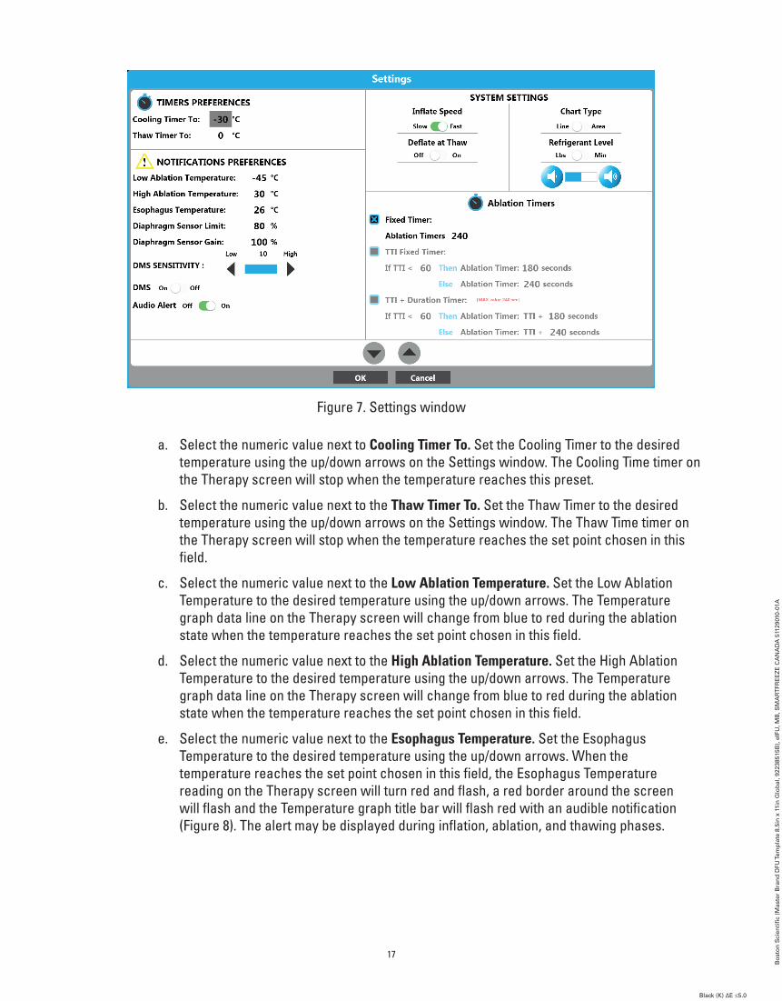
Figure 7. Settings window
a. Select the numeric value next to Cooling Timer To. Set the Cooling Timer to the desired temperature using the up/down arrows on the Settings window. The Cooling Time timer on the Therapy screen will stop when the temperature reaches this preset.
b. Select the numeric value next to the Thaw Timer To. Set the Thaw Timer to the desired temperature using the up/down arrows on the Settings window. The Thaw Time timer on the Therapy screen will stop when the temperature reaches the set point chosen in this field.
c. Select the numeric value next to the Low Ablation Temperature. Set the Low Ablation Temperature to the desired temperature using the up/down arrows. The Temperature graph data line on the Therapy screen will change from blue to red during the ablation state when the temperature reaches the set point chosen in this field.
d. Select the numeric value next to the High Ablation Temperature. Set the High Ablation Temperature to the desired temperature using the up/down arrows. The Temperature graph data line on the Therapy screen will change from blue to red during the ablation state when the temperature reaches the set point chosen in this field.
e. Select the numeric value next to the Esophagus Temperature. Set the Esophagus Temperature to the desired temperature using the up/down arrows. When the temperature reaches the set point chosen in this field, the Esophagus Temperature reading on the Therapy screen will turn red and flash, a red border around the screen will flash and the Temperature graph title bar will flash red with an audible notification (Figure 8). The alert may be displayed during inflation, ablation, and thawing phases.
17
Bo
sto
n S
cien
tifi
c (M
aste
r B
ran
d D
FU Te
mp
late
8.5
in x
11i
n G
lob
al, 9
2238
515B
), e
IFU
, MB
, SM
AR
TFR
EE
ZE
CA
NA
DA
511
2901
0-01
A
Black (K) ∆E ≤5.0Black (K) ∆E ≤5.0

Figure 8. Esophagus temperature alert
f. Select the numeric value next to the Diaphragm Sensor Limit. Set the Diaphragm Sensor Limit to the desired percentage using the up/down arrows. When the percentage reaches the set point chosen in this field, the Diaphragm Sensor reading on the Therapy screen will turn red and flash, a red border around the screen will flash and the Temperature graph title bar will flash red with the audible notification when the percentage reaches the set point chosen in this field (Figure 9). The alert may be displayed during the ablation phase.
Figure 9. Diaphragm Movement Sensor Alert
18
Bo
sto
n S
cien
tifi
c (M
aste
r B
ran
d D
FU Te
mp
late
8.5
in x
11i
n G
lob
al, 9
2238
515B
), e
IFU
, MB
, SM
AR
TFR
EE
ZE
CA
NA
DA
511
2901
0-01
A
Black (K) ∆E ≤5.0Black (K) ∆E ≤5.0

g. Select the numeric value next to the Diaphragm Sensor Gain. Set the Diaphragm Sensor Gain to the desired percentage. The Diaphragm Movement graph on the Therapy screen will zoom into the set percentage (used to see smaller signal responses)
h. Set the DMS Sensitivity to the desired level using the low and high arrows. (Used to set the DMS detection threshold. Lower settings require stronger DMS signals in order to be registered, and higher settings allow weaker DMS signals to be registered).
i. Optional: Slide the DMS to the Off position to disable the DMS on the Therapy screen. (Typically used when ablating veins that do not affect the phrenic nerve).
j. Optional: Slide the Audio Alert to the Off position to disable the audible notification if the DMS Sensor Limit and Esophagus Temperature notifications are triggered.
k. Optional: Set the inflation speed to slow by sliding the Inflate Speed slider to Slow. The default is set to Fast.
l. Optional: Set the Cryo-balloon Temperature chart on the Therapy screen to display a filled in area graph by sliding the Chart Type slider to Area. The default is set to Line.
m. Optional: Set the N2O Tank level meter on the Therapy screen to display in lbs by sliding the Refrigerant Level slider to Lbs. The default is set to minutes.
n. Optional: Set the alert volume level to the desired setting by pressing the button to
lower the volume or the button to raise it. The default is set to mid-range.
o. Slide the Deflate At Thaw slider to ON to enable the auto deflate feature.
Note: The auto deflate feature is used to automatically deflate the cryo-balloon when the thaw temperature (20°C) is reached. The auto deflate feature is OFF by default.
p. Select the desired Ablation Timers setting from the three options:
• Fixed Timer
Set the Fixed Timer to the desired time using the up/down arrows on the Settings window. The ablation will stop when the Ablation Time reaches the set point chosen in this field. The Ablation Time may also be set directly on the Therapy screen using the white up/down arrows.
• TTI Fixed Timer
This timer option allows the user to predetermine the total amount of ablation time based on the time to vein isolation.
This option requires three (3) user settings: Time To Isolation (TTI), shorter duration (Then), and longer duration (Else).
If the vein is isolated sooner than the user-set TTI time, the total ablation time will be the shorter duration. If the vein is isolated at or later than the user-set TTI time, the total ablation time will be the longer duration. The three set points are adjusted by selecting the desired setting and using the up/down arrows.
The TTI set point is adjustable in 10 second increments beginning with 30 seconds up to a maximum of 10 seconds less than the shorter duration setting.
19
Bo
sto
n S
cien
tifi
c (M
aste
r B
ran
d D
FU Te
mp
late
8.5
in x
11i
n G
lob
al, 9
2238
515B
), e
IFU
, MB
, SM
AR
TFR
EE
ZE
CA
NA
DA
511
2901
0-01
A
Black (K) ∆E ≤5.0Black (K) ∆E ≤5.0

(For example, the TTI can be adjusted from 30 to 170 if the shorter duration is set to 180 seconds).
The shorter duration is adjustable in 30 second increments beginning with 60 seconds (if the TTI user setting is set to 50 seconds or less) to a maximum of 30 seconds less than the longer duration (maximum of 210 seconds).
The longer duration is adjustable in 30 second increments beginning with 90 seconds (if the shorter duration user setting is set to 60 seconds) to 240 seconds.
If TTI Fixed Timer option is chosen, the ablation duration on the Therapy screen will display the longer ablation time setting. If the user indicates that the vein is isolated prior to the set point, the Ablation Duration will change to the shorter ablation time and flash for a few seconds. Each time the ablation duration is changed automatically by the console, the ablation duration flashes.
• TTI + Duration Timer
This timer option allows the user to predetermine the amount of additional ablation time based on the time to vein isolation.
This option requires three (3) user settings: Time To Isolation (TTI), Shorter Additional Time (Then), and Longer Additional Time (Else).
If the vein is isolated sooner than the user set TTI time, the ablation will last the shorter additional time from the TTI time. If the vein is isolated at or later than the user set TTI time, then the total ablation will last the longer additional time from the TTI time. The three set points are adjusted by selecting the desired setting and using the up/down arrows.
The TTI set point is adjustable in 10 second increments from 30 seconds to 210 seconds.
The shorter additional time is adjustable in 30 second increments beginning with 60 seconds (if the TTI user setting is set to 50 seconds or less) to a maximum of 30 seconds less than the longer duration (maximum of 210 seconds).
The longer additional time is adjustable in 30 second increments beginning with 60 seconds (if the shorter duration user setting is set to 60 seconds) to 240 seconds.
If this option is chosen, the ablation duration will display 240 seconds regardless of the set points on the settings screen. If the user indicates that the vein is isolated before the set point, the ablation duration will display the current ablation time plus the shorter time. If the user indicates that the vein is isolated after this set point, the ablation duration will display the current ablation time plus the longer time setting. Each time the ablation duration is changed automatically by the console, the ablation duration flashes. Note that the maximum ablation time is always 240 seconds.
20
Bo
sto
n S
cien
tifi
c (M
aste
r B
ran
d D
FU Te
mp
late
8.5
in x
11i
n G
lob
al, 9
2238
515B
), e
IFU
, MB
, SM
AR
TFR
EE
ZE
CA
NA
DA
511
2901
0-01
A
Black (K) ∆E ≤5.0Black (K) ∆E ≤5.0

8.2.3.2 Beginning Cryoablation ProcedureThe ablation procedure for the isolation of pulmonary veins follows the following algorithm:
Figure 10.
Inflate Cryo-balloon
Position Cryo-balloon
Freeze
Thaw
Deflate Cryo-balloon
Reposition/remove Cryo-balloon
Ablation procedure algorithm
1. Inflate the cryo-balloon when desired using one of the following three (3) methods:
• Press the START pushbutton on the console front panel
• Press the START foot switch pedal (right pedal, green)
• Press the INFLATE button on the therapy screen
When the cryo-balloon has reached the inflated state, the following indicators will be visible in the Therapy screen (Figure 11). The STATUS bar will indicate INFLATION; the catheter illustration will depict an inflated balloon; the STOP and ABLATE buttons will appear; the diaphragm movement data will be plotted on the DIAPHRAGM MOVEMENT graph and the esophagus temperature will be displayed under ESOPHAGUS TEMPERATURE.
Additionally, the START pushbutton on the console front panel will be illuminated blue and the Stop pushbutton on the console front panel will be illuminated white.
21
Bo
sto
n S
cien
tifi
c (M
aste
r B
ran
d D
FU Te
mp
late
8.5
in x
11i
n G
lob
al, 9
2238
515B
), e
IFU
, MB
, SM
AR
TFR
EE
ZE
CA
NA
DA
511
2901
0-01
A
Black (K) ∆E ≤5.0Black (K) ∆E ≤5.0

Figure 11. Therapy screen – inflation state
Note: If necessary, the cryo-balloon can be deflated from the INFLATION state using one of the following methods:
• Pressing the Stop pushbutton on the console front panel.
• Pressing the Stop foot switch pedal (left pedal, orange).
• Pressing the Stop button on the Therapy screen.
2. Position the inflated cryo-balloon per standard clinical practice and verify that the vein is properly occluded.
3. Start the cryoablation treatment using one of the following three (3) methods:
• Press the START pushbutton on the console front panel.
• Press the START foot switch pedal (right pedal, green).
• Press the ABLATE button on the therapy screen .
Note: If necessary while in the ABLATION state, the injection can be stopped and the cryo-balloon can be deflated by one of the following methods:
• Press the STOP push button on the console front panel to stop injection. Press the STOP button again to deflate the cryo-balloon.
• Press the STOP foot switch pedal (left pedal, orange) to stop injection. Press the STOP foot switch pedal again to deflate the cryo-balloon.
• Press the STOP button on the Therapy screen to stop injection. Press the STOP button again to deflate the cryo-balloon.
22
Bo
sto
n S
cien
tifi
c (M
aste
r B
ran
d D
FU Te
mp
late
8.5
in x
11i
n G
lob
al, 9
2238
515B
), e
IFU
, MB
, SM
AR
TFR
EE
ZE
CA
NA
DA
511
2901
0-01
A
Black (K) ∆E ≤5.0Black (K) ∆E ≤5.0

Figure 12. Therapy screen–ablation state
4. When the system is in the ABLATION state, the following indicators will be visible in the Therapy screen (Figure 12):
• The STATUS bar will indicate ABLATION
• The ABLATE button will be replaced with a STOP button
• The cryo-balloon temperature is plotted on the Cryoballoon Temperature graph.
• The Temperature reading begins to drop.
• The catheter illustration will change to the ablation timer and the Ablation Time timer begins to increment.
• A flashing snowflake will appear above the ablation timer.
• The Temperature Rate displays a negative value (current rate).
• The Minimum Temperature displays the lowest temperature recorded.
• The Treatment Notes option becomes available.
• Press the Treatment Notes button on the Therapy screen to add observations and other relevant information to the treatment file (Figure 13).
• Press the white space in the Treatment Notes window and then on the button to display the on-screen keyboard.
• Press the OK button to save the added notes or Cancel to close the Treatment Notes window without saving them.
23
Bo
sto
n S
cien
tifi
c (M
aste
r B
ran
d D
FU Te
mp
late
8.5
in x
11i
n G
lob
al, 9
2238
515B
), e
IFU
, MB
, SM
AR
TFR
EE
ZE
CA
NA
DA
511
2901
0-01
A
Black (K) ∆E ≤5.0Black (K) ∆E ≤5.0

Figure 13. Treatment Notes window
• The diaphragm movement data will be plotted on the Diaphragm Movement graph and the current amplitude will be displayed as percent. The percentage is based on the measured response at the start of the ablation phase and will decrease as the patient’s response to the pacing signal decreases. If the percentage reaches the setpoint, the current diaphragm movement percentage will be displayed in a red circle and flash, a red border around the screen will flash and the Temperature graph title bar will flash red with the audible notification (Figure 9). The alert is present during the ablation phase. If the DMS reading is less than the DMS sensitivity setting, the DMS graph will indicate “No Pacing Detected”. The DMS graph has a white line that adjusts to the average DMS value seen.
Note: Never rely solely on this indicator. It is for reference only.
• The current esophageal temperature data will be displayed in °C. If the temperature reaches the setpoint, the current temperature will be displayed in a red circle and flash, a red border around the screen will flash and the Temperature graph title bar will flash red with the audible notification (Figure 8). The alert is present during inflation, ablation, and thawing phases.
Note: Never rely solely on this indicator. It is for reference only.
• When the temperature reaches the Cooling Timer temperature setpoint, the measured time is displayed.
Note: During the ablation phase, the console will periodically emit an audible sound. To
adjust the volume level, press the button to lower the volume and the button to raise the volume.
• When the vein is determined to be isolated, press the button or press and hold the green foot switch pedal for three seconds. Once pressed, the Time to Effect will display the time in seconds since the ablation began.
Note: A green dot is displayed on the temperature graph at the vein isolated point. The vein isolated point can be updated by pressing the vein isolated button again or by pressing and holding the green foot switch pedal for three seconds. If updated, the green dot will be displaced to the new isolation point.
24
Bo
sto
n S
cien
tifi
c (M
aste
r B
ran
d D
FU Te
mp
late
8.5
in x
11i
n G
lob
al, 9
2238
515B
), e
IFU
, MB
, SM
AR
TFR
EE
ZE
CA
NA
DA
511
2901
0-01
A
Black (K) ∆E ≤5.0Black (K) ∆E ≤5.0

5. Wait for the ablation timer to end.
Note: Once the timer reaches the ablation set time, the ablation treatment automatically stops and the thawing phase begins. The system state will indicate THAWING (Figure 14) and the ABLATE and STOP buttons are displayed on the Therapy screen. In addition, the START pushbutton on the console front panel will be illuminated blue and the stop pushbutton will be illuminated white.
Figure 14. Therapy screen–thawing state
When the system is in the THAWING state, the following indicators can be observed on the Therapy screen:
• The cryo-balloon temperature continues to be plotted on the Balloon Temperature graph
• The Temperature reading begins to rise.
• The Ablation Time timer is stopped and changes to an illustration of the inflated catheter.
• The Temperature Rate displays a positive value (current rate).
• The Minimum Temperature displays the lowest temperature recorded.
• When the temperature reaches the Thaw Timer temperature setpoint, the measured time is displayed.
6. If the Auto Deflate feature is OFF (see step 9 if Auto Deflate is ON):
a. Wait for the cryo-balloon thawing to complete. Thawing is complete when the cryo-balloon temperature reaches 20°C.
b. To start a new treatment without re-positioning the cryo-balloon, perform one of the following:
• Press the START pushbutton on the console front panel.
25
Bo
sto
n S
cien
tifi
c (M
aste
r B
ran
d D
FU Te
mp
late
8.5
in x
11i
n G
lob
al, 9
2238
515B
), e
IFU
, MB
, SM
AR
TFR
EE
ZE
CA
NA
DA
511
2901
0-01
A
Black (K) ∆E ≤5.0Black (K) ∆E ≤5.0

• Press the START foot switch pedal (right pedal, green) • Press the ABLATE button on the Therapy screen (Figure 14).
c. If another treatment in the same location is not necessary, deflate the cryo-balloon by doing one of the following: • Extending the Deflation Switch on the catheter handle
• Pressing the Stop pushbutton on the console front panel. • Pressing the Stop foot switch pedal (left pedal, orange) • Pressing the Stop button on the Therapy screen.
Note: Extending the Deflation Switch on the catheter handle elongates the cryo-balloon to its maximum length and allows it to wrap uniformly.
Figure 15. READY state
d. The following activity can be observed on the Therapy screen when moving from the Thawing state to the READY state: • The system state will first indicate IDLE and then indicate READY as the system evacuates remaining refrigerant from the injection line. • The START pushbutton on the console front panel will be illuminated green when in the READY state. • The ABLATE button on the Therapy screen disappears in IDLE state and the INFLATE button appears in the READY state. • The PLAYBACK button appears allowing data from the previous ablations to be reviewed. Press the PLAYBACK button to enter the Playback Mode, shown in Figure 16. • The status indicator is replaced with a Playback Mode indication and the Exit Playback button appears.
Note: The system automatically exits playback mode if a new inflation is started.
26
Bo
sto
n S
cien
tifi
c (M
aste
r B
ran
d D
FU Te
mp
late
8.5
in x
11i
n G
lob
al, 9
2238
515B
), e
IFU
, MB
, SM
AR
TFR
EE
ZE
CA
NA
DA
511
2901
0-01
A
Black (K) ∆E ≤5.0Black (K) ∆E ≤5.0

e. Select a point on the cryo-balloon Temperature graph. The corresponding recorded information from that moment will be displayed.
• Use the Treatment arrows (Figure 16) to display data from previous treatments within the current procedure.
• In playback mode, the ablation site for each treatment may be updated by pressing the ablation site button and selecting the desired ablation site from the dropdown menu.
• Press the Exit Playback button on the Therapy screen to manually exit playback mode.
Figure 16. Playback mode
7. To start a new treatment, follow this procedure from step 3 on page 22.
8. If additional treatment is not necessary, ensure the balloon is deflated then retract the cryo-balloon into the sheath and remove the catheter from the patient.
9. If the Auto Deflate feature is ON and the cryo-balloon needs to be retracted into the sheath:
a. When the Temperature reaches 20°C, the cryo-balloon will automatically deflate.
Note: To elongate the balloon during deflation, press forward on the POLARx™ Slider Extension Switch.
b. Retract the cryo-balloon into the sheath and remove the catheter from the patient.
27
Bo
sto
n S
cien
tifi
c (M
aste
r B
ran
d D
FU Te
mp
late
8.5
in x
11i
n G
lob
al, 9
2238
515B
), e
IFU
, MB
, SM
AR
TFR
EE
ZE
CA
NA
DA
511
2901
0-01
A
Black (K) ∆E ≤5.0Black (K) ∆E ≤5.0

10. If the Auto Deflate feature is ON and the cryo-balloon does not need to be retracted into the sheath:
a. When the Temperature reaches 20°C, the cryo-balloon will automatically deflate.
b. If additional treatment is not necessary, retract the cryo-balloon into the sheath and remove the catheter from the patient.
Note: It is possible—though it is not recommended— to manually deflate the cryo-balloon before the cryo-balloon reaches 20°C by one of the following methods:
• Pressing the Stop pushbutton on the console front panel. • Pressing the Stop foot switch pedal (left pedal, orange). • Pressing the Stop button on the Therapy screen.
8.2.4 Procedure termination1. When treatment is completed, press the Complete Procedure button on the Therapy screen
(Figure 15) or the Playback screen (Figure 16). The Summary Report screen is presented (Figure 17).
Figure 17. Summary report
Screen activity: The following can be observed on the Summary Report Screen:
• The Patient ID number is displayed at the top left of the screen. If the logged-in user is the doctor that performed the procedure, all patient information will be displayed. Note that the patient information also includes a calculated BMI based on the entered patient weight and height.
• The Procedure configuration information is displayed at the top right of the screen.
28
Bo
sto
n S
cien
tifi
c (M
aste
r B
ran
d D
FU Te
mp
late
8.5
in x
11i
n G
lob
al, 9
2238
515B
), e
IFU
, MB
, SM
AR
TFR
EE
ZE
CA
NA
DA
511
2901
0-01
A
Black (K) ∆E ≤5.0Black (K) ∆E ≤5.0

• Each of the treatments that were performed during the procedure are individually entered in the Treatment Info table. The ablation site, duration, minimum ESO temperature, temperature rate, lowest temperature achieved, time to ablation temperature, minimum DMS value and time to thaw temperature as well as any notes that were added per treatment can be seen.
• The ablation site for each treatment may be updated by pressing the clipboard icon in the ablation site column next to each treatment.
• The ablation summary displayed on the Therapy screen is repeated on the Summary Report screen on the bottom left of the screen.
2. Click on the clipboard icon in the Notes column to add/edit the treatment notes.
3. Click on the check-marked clipboard icon to add/edit an overall patient diagnosis. The Diagnosis window is displayed.
4. Press the OK button to save the patient diagnosis and close the Diagnosis window or the Cancel button to close the window without saving.
5. Click on the icon to add/edit an overall procedure outcome. The Outcome window is displayed.
6. Press the OK button to save the procedure outcome and close the Outcome window or Cancel to close the window without saving.
7. Press the Return to Procedure button to return to the Therapy screen if additional treatments are required.
8. Press the End Procedure button to end the procedure and return to the Home screen.
Note: Once the procedure is ended, it is possible to continue treatment without creating a new procedure record if the Load Previous Patient button is pressed. Once the Therapy screen is accessed with new patient information, it is no longer possible to continue a previous patient’s treatment.
9. To review the patient records, see section 11.1 on page 35.
29
Bo
sto
n S
cien
tifi
c (M
aste
r B
ran
d D
FU Te
mp
late
8.5
in x
11i
n G
lob
al, 9
2238
515B
), e
IFU
, MB
, SM
AR
TFR
EE
ZE
CA
NA
DA
511
2901
0-01
A
Black (K) ∆E ≤5.0Black (K) ∆E ≤5.0

9. SYSTEM SHUTDOWN1. Press the Shutdown button on the home screen.
Note: If the Shutdown button is not in the center forefront, pressing the button a second time will be necessary.
2. Press the Yes button on the message window.
Figure 18. Shutdown message
Note: When the system shutdown is complete, the screen will briefly display ”Entering Sleep Mode” and then will go black.
3. After shutdown is complete, turn off the main power switch located on the rear of the console.
4. Pull open the console door at the rear of the console to expose the refrigerant tank.
5. Turn the refrigerant tank knob clockwise to close the tank valve.
6. Disconnect the AC power cord from the hospital AC source (wall outlet).
7. Disconnect the scavenging hose from the hospital evacuation system.
8. Remove the Diaphragm Movement Sensor from the patient.
9. Disconnect the Diaphragm Movement Sensor from the ICB.
10. Remove the Esophagus Temperature Sensor from the patient.
11. Disconnect the Esophagus Temperature Sensor from the ETS Extension harness.
12. Disconnect the ETS Extension harness from the ICB.
13. Disconnect the Catheter Extension harness from the ICB.
14. Disconnect the ICB from the console.
15. Disconnect the Cryo-Cable from the console.
16. Dispose of all single-use items according to standard hospital procedures.
17. Store the reusable items in the console as follows:
a. Clean items according to standard hospital procedures.
b. Wrap the AC Power cord around the designated hooks on the console door.
c. Wrap the scavenging hose around the designated scavenging hose hooks on the side of the console.
30
Bo
sto
n S
cien
tifi
c (M
aste
r B
ran
d D
FU Te
mp
late
8.5
in x
11i
n G
lob
al, 9
2238
515B
), e
IFU
, MB
, SM
AR
TFR
EE
ZE
CA
NA
DA
511
2901
0-01
A
Black (K) ∆E ≤5.0Black (K) ∆E ≤5.0

d. Wrap the DMS in a loop and store in the pocket found inside the console.
e. Wrap the ETS Extension harness in a loop and store in the pocket found inside the console.
f. Wrap the ICB harness in a loop and store in the designated location on the side of the console.
18. Close the console door.
10. USER PROFILESThe system employs three types of user profile (User, Administrator, and Doctor) to control access to five system functions (Cryotherapy, Records, Settings, Change Tank, Shut Down). User profiles are separate and distinct from patient profiles.
Cryo Therapy Records Settings Change Tank Shut Down
User • • •
Administrator • • • •
Doctor • • • •
Figure 19. User access capability matrix
Users are prompted to login if a session is not already in progress. Active sessions are indicated by the presence of a user icon at the bottom center of the Home screen (Figure 2). Permission to proceed will be denied if the logged in user profile does not support a given function (Figure 3).
Tap the user icon at the bottom center of the screen to log out of a session.
10.1 Creating and editing user profiles
Note: Only administrator profiles have access to the Settings screen.
All user profile creation and maintenance must be performed by an administrator via the settings option on the home screen.
31
Bo
sto
n S
cien
tifi
c (M
aste
r B
ran
d D
FU Te
mp
late
8.5
in x
11i
n G
lob
al, 9
2238
515B
), e
IFU
, MB
, SM
AR
TFR
EE
ZE
CA
NA
DA
511
2901
0-01
A
Black (K) ∆E ≤5.0Black (K) ∆E ≤5.0

10.2 Creating and Managing Users
Figure 20. System settingsThe system settings screen (Figure 20) contains the Manage Users icon and a software timer that indicates the amount of time the console software has been in operation. Click the Manage Users icon to begin.
Figure 21. Manage Users home screenThe Manage Users home screen (Figure 21) provides services to add new users and new doctors, edit users/doctors, delete users/doctors, and reset passwords.
32
Bo
sto
n S
cien
tifi
c (M
aste
r B
ran
d D
FU Te
mp
late
8.5
in x
11i
n G
lob
al, 9
2238
515B
), e
IFU
, MB
, SM
AR
TFR
EE
ZE
CA
NA
DA
511
2901
0-01
A
Black (K) ∆E ≤5.0Black (K) ∆E ≤5.0

Figure 22. Creating a new userNew users are created by entering the user name, password, and password confirmation. The Admin slider switch determines whether or not the user is placed in the administrators group (Figure 22).
Figure 23. New doctor setup
The Setup New Doctor screen (Figure 23) allows a doctor’s individual procedure settings and preferences to be preset and then loaded whenever that physician is selected at the beginning of a procedure.
33
Bo
sto
n S
cien
tifi
c (M
aste
r B
ran
d D
FU Te
mp
late
8.5
in x
11i
n G
lob
al, 9
2238
515B
), e
IFU
, MB
, SM
AR
TFR
EE
ZE
CA
NA
DA
511
2901
0-01
A
Black (K) ∆E ≤5.0Black (K) ∆E ≤5.0

To edit a user or a doctor, select the subject from the user list and tap the Edit icon. For users, only user names and access levels can be edited. In the case of doctors, the doctor’s name and individual settings/preferences can be edited.
To delete a user, select the user from the list and tap the Delete icon.
To reset a user/doctor password, select the subject and press the Reset Password icon. Note: the logged-in administrator must enter their own password first.
10.3 Archiving Records
Archiving records allows the system to continue to be used when the available hard drive space is too low.
Press the Archive Records button on the Settings screen.
Note: Once archived, the records are not viewable on the console.
Press Yes to Archive the patient records on the console. Press No to cancel the archiving process.
After the archiving procedure is complete, press OK to close the window.
Note: The console will shut down after pressing OK.
Figure 24. Archive Confirmation10.4 Directions For Use (DFU)
The DFU can be found on every user screen.
Press the (image of the DFU button) to display the DFU.
Note: The DFU is not available for display when N2O is flowing in and out of the console.
To change the language of the DFU to another supported language, press the drop down arrow next to the Language setting on the Settings screen and select the desired language.
11. REVIEW AND EXPORT TREATMENT RECORDS
Note: Only doctor profiles have access to treatment records. Moreover, only the doctor profile (attending physician) associated with a given patient treatment file is permitted to review and/or export records from that file. The doctor must be logged in to review treatment records.
34
Bo
sto
n S
cien
tifi
c (M
aste
r B
ran
d D
FU Te
mp
late
8.5
in x
11i
n G
lob
al, 9
2238
515B
), e
IFU
, MB
, SM
AR
TFR
EE
ZE
CA
NA
DA
511
2901
0-01
A
Black (K) ∆E ≤5.0Black (K) ∆E ≤5.0

11.1 Review Treatment Records
1. Press the Records button on the Home screen (Figure 25).
Figure 25. Home screen
Figure 26. Login screen
2. Enter physician’s user name and password.
3. Press the OK button on the login screen
If the entered user name and password have the necessary rights, the Treatment Records screen is displayed (Figure 27).
35
Bo
sto
n S
cien
tifi
c (M
aste
r B
ran
d D
FU Te
mp
late
8.5
in x
11i
n G
lob
al, 9
2238
515B
), e
IFU
, MB
, SM
AR
TFR
EE
ZE
CA
NA
DA
511
2901
0-01
A
Black (K) ∆E ≤5.0Black (K) ∆E ≤5.0

Figure 27. Treatment Records screen
The following can be observed on the Treatment Records screen:
• The Procedure Records list is displayed on the right of the screen. The list can be sorted by patient first name, last name, or by case date. To sort from A to Z by one of these categories, press on the First Name, Last Name or Case Date column titles. Press a second time to sort from Z to A.
• The Patient Information is displayed on the top left of the screen.
• The Procedure configuration information is displayed at the top right of the screen.
• The recorded procedure data is displayed on the left of the screen.
4. Select a procedure record from the list. The corresponding recorded data is displayed.
5. Select a point on the graph to display the corresponding data from that moment during the treatment.
6. If more than one treatment was performed during the selected case, use the Treatment arrows (Figure 27) to display data from the different treatments performed.
7. Press the Summary Report button on the Treatment Records screen to display the summary of all treatments from the selected case (Figure 28).
36
Bo
sto
n S
cien
tifi
c (M
aste
r B
ran
d D
FU Te
mp
late
8.5
in x
11i
n G
lob
al, 9
2238
515B
), e
IFU
, MB
, SM
AR
TFR
EE
ZE
CA
NA
DA
511
2901
0-01
A
Black (K) ∆E ≤5.0Black (K) ∆E ≤5.0
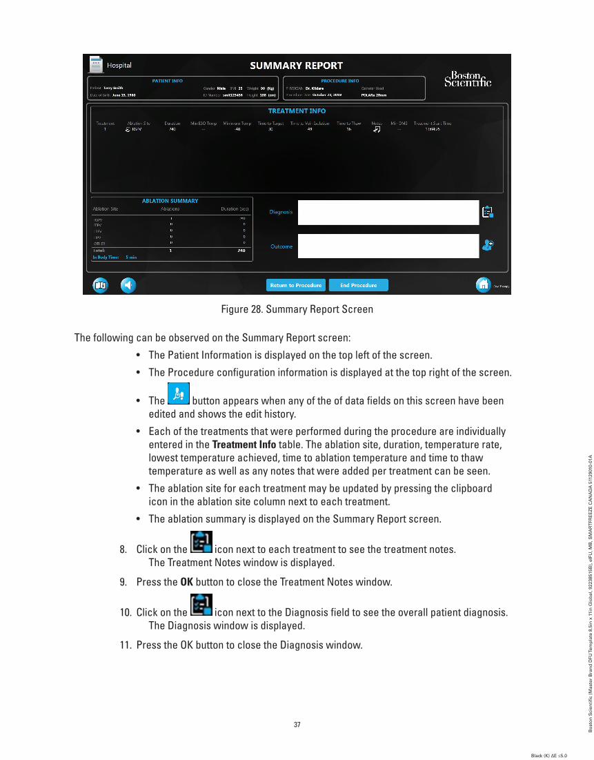
Figure 28. Summary Report Screen
The following can be observed on the Summary Report screen:
• The Patient Information is displayed on the top left of the screen.
• The Procedure configuration information is displayed at the top right of the screen.
• The button appears when any of the of data fields on this screen have been edited and shows the edit history.
• Each of the treatments that were performed during the procedure are individually entered in the Treatment Info table. The ablation site, duration, temperature rate, lowest temperature achieved, time to ablation temperature and time to thaw temperature as well as any notes that were added per treatment can be seen.
• The ablation site for each treatment may be updated by pressing the clipboard icon in the ablation site column next to each treatment.
• The ablation summary is displayed on the Summary Report screen.
8. Click on the icon next to each treatment to see the treatment notes. The Treatment Notes window is displayed.
9. Press the OK button to close the Treatment Notes window.
10. Click on the icon next to the Diagnosis field to see the overall patient diagnosis. The Diagnosis window is displayed.
11. Press the OK button to close the Diagnosis window.
37
Bo
sto
n S
cien
tifi
c (M
aste
r B
ran
d D
FU Te
mp
late
8.5
in x
11i
n G
lob
al, 9
2238
515B
), e
IFU
, MB
, SM
AR
TFR
EE
ZE
CA
NA
DA
511
2901
0-01
A
Black (K) ∆E ≤5.0Black (K) ∆E ≤5.0

12. Click on the icon to see the overall procedure outcome. The Outcome window is displayed.
13. Press the OK button to close the Outcome window.
14. Press the Back To Treatment Record button to return to the Treatment Records screen.
11.2 Export Treatment Records
1. Insert a USB drive into the USB slot on the front panel.
2. Select the procedure record that will be exported from the list of procedure records.
3. Press on the Save to USB button on the Treatment Records screen.
Note: The Save to USB button on the Treatment Records screen is not available until the console has successfully recognized the USB drive.
The Save to USB Drive window will be displayed (Figure 29).
Figure 29. Save to USB Drive window
4. Select the file type desired.
5. Press the OK button on the Save to USB Drive window or CANCEL to return to the Treatment Records screen without saving.
Note: Once the file has successfully been exported to the USB drive, the Procedure Saved Successfully window will be displayed (Figure 30).
Figure 30. Procedure successfully saved window
6. Press the OK button on the Procedure Saved Successfully window.
38
Bo
sto
n S
cien
tifi
c (M
aste
r B
ran
d D
FU Te
mp
late
8.5
in x
11i
n G
lob
al, 9
2238
515B
), e
IFU
, MB
, SM
AR
TFR
EE
ZE
CA
NA
DA
511
2901
0-01
A
Black (K) ∆E ≤5.0Black (K) ∆E ≤5.0

7. Remove the USB drive from the USB slot on the console front panel.
Note: It is recommended that dedicated USB drives be used to store console procedure records to ensure the security of patient health information.
Note: The exported information contains all the recorded information from the selected case. Recorded information begins from Ablation state of the procedure and ends after the Thawing state.
11.3 Report Printing
If a BSC supplied printer is connected to one of the console USB ports, the PDF report may be printed.
Press the Print Report button on the Records screen.
12. TROUBLESHOOTING
System Notice Number
Problem Action
00000020-1 Low refrigerant level in the tank.
Consider replacing the refrigerant tank soon.
00000200-1 The tank pressure is too low.
Ensure that the refrigerant tank valve is open. If the problem persists, replace the tank. If the problem persists, contact Boston Scientific technical support and provide the message code.
00040000-1 The subcooler temperature is too high.
Wait 5 minutes before attempting the next ablation. If the problem persists, contact Boston Scientific technical support and provide the message code.
00200000-1 The system has detected a stuck command.
One of the Start/Stop commands (Pushbuttons, Foot Switch or Screen input) is defective. If one of the Start commands is stuck, the case may be completed using one of the other Start commands. If one of the Stop commands is stuck, the case cannot be continued. Contact Boston Scientific technical support and provide the message code.
1 - 00000004-2 The inner balloon pressure is too high.
Try another ablation. If the problem persists, replace the cryocable then the catheter. If the problem persists, contact Boston Scientific technical support and provide the error code.
1 - 00000008-2 The inner balloon pressure is too low.
Repeat the inflation, if the problem persists replace the catheter.
1 - 00000020-2 The outer balloon pressure is too high.
Disconnect and reconnect the cryocable from the console and catheter. If the problem persists, replace the catheter and cryocable. If the problem persists, contact Boston Scientific technical support and provide the error code.
1 - 00001000-2 The balloon temperature is too low. The catheter might be too deep in the vein.
Reposition the catheter and try another ablation.
1 - 00004000-2 The console detected blood in the catheter.
Replace the catheter. Do not attempt any more inflations or ablations with this catheter.
1 - 00008000-2 The console detected a problem with the blood detection circuit in the catheter.
Replace the catheter. Do not attempt any more inflations or ablations with this catheter.
39
Bo
sto
n S
cien
tifi
c (M
aste
r B
ran
d D
FU Te
mp
late
8.5
in x
11i
n G
lob
al, 9
2238
515B
), e
IFU
, MB
, SM
AR
TFR
EE
ZE
CA
NA
DA
511
2901
0-01
A
Black (K) ∆E ≤5.0Black (K) ∆E ≤5.0
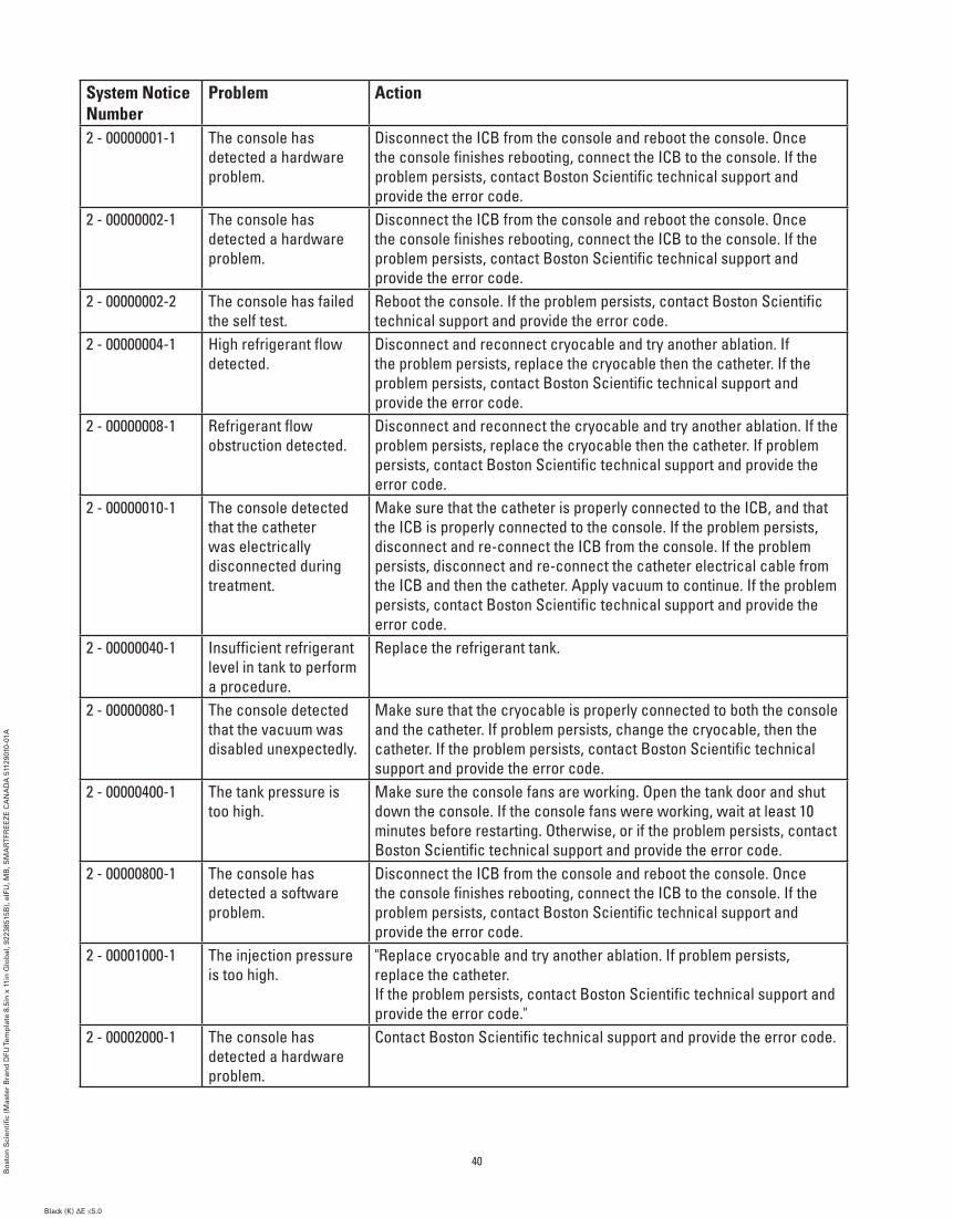
System Notice Number
Problem Action
2 - 00000001-1 The console has detected a hardware problem.
Disconnect the ICB from the console and reboot the console. Once the console finishes rebooting, connect the ICB to the console. If the problem persists, contact Boston Scientific technical support and provide the error code.
2 - 00000002-1 The console has detected a hardware problem.
Disconnect the ICB from the console and reboot the console. Once the console finishes rebooting, connect the ICB to the console. If the problem persists, contact Boston Scientific technical support and provide the error code.
2 - 00000002-2 The console has failed the self test.
Reboot the console. If the problem persists, contact Boston Scientific technical support and provide the error code.
2 - 00000004-1 High refrigerant flow detected.
Disconnect and reconnect cryocable and try another ablation. If the problem persists, replace the cryocable then the catheter. If the problem persists, contact Boston Scientific technical support and provide the error code.
2 - 00000008-1 Refrigerant flow obstruction detected.
Disconnect and reconnect the cryocable and try another ablation. If the problem persists, replace the cryocable then the catheter. If problem persists, contact Boston Scientific technical support and provide the error code.
2 - 00000010-1 The console detected that the catheter was electrically disconnected during treatment.
Make sure that the catheter is properly connected to the ICB, and that the ICB is properly connected to the console. If the problem persists, disconnect and re-connect the ICB from the console. If the problem persists, disconnect and re-connect the catheter electrical cable from the ICB and then the catheter. Apply vacuum to continue. If the problem persists, contact Boston Scientific technical support and provide the error code.
2 - 00000040-1 Insufficient refrigerant level in tank to perform a procedure.
Replace the refrigerant tank.
2 - 00000080-1 The console detected that the vacuum was disabled unexpectedly.
Make sure that the cryocable is properly connected to both the console and the catheter. If problem persists, change the cryocable, then the catheter. If the problem persists, contact Boston Scientific technical support and provide the error code.
2 - 00000400-1 The tank pressure is too high.
Make sure the console fans are working. Open the tank door and shut down the console. If the console fans were working, wait at least 10 minutes before restarting. Otherwise, or if the problem persists, contact Boston Scientific technical support and provide the error code.
2 - 00000800-1 The console has detected a software problem.
Disconnect the ICB from the console and reboot the console. Once the console finishes rebooting, connect the ICB to the console. If the problem persists, contact Boston Scientific technical support and provide the error code.
2 - 00001000-1 The injection pressure is too high.
"Replace cryocable and try another ablation. If problem persists, replace the catheter. If the problem persists, contact Boston Scientific technical support and provide the error code."
2 - 00002000-1 The console has detected a hardware problem.
Contact Boston Scientific technical support and provide the error code.
40
Bo
sto
n S
cien
tifi
c (M
aste
r B
ran
d D
FU Te
mp
late
8.5
in x
11i
n G
lob
al, 9
2238
515B
), e
IFU
, MB
, SM
AR
TFR
EE
ZE
CA
NA
DA
511
2901
0-01
A
Black (K) ∆E ≤5.0Black (K) ∆E ≤5.0

System Notice Number
Problem Action
2 - 00004000-1 Flow obstruction detected.
Disconnect and reconnect the cryocable. If problem persists, replace the catheter. If problem persists, contact Boston Scientific technical support and provide the error code.
2 - 00008000-1 The console has detected a hardware problem.
Disconnect the ICB from the console and reboot the console. Once the console finishes rebooting, connect the ICB to the console. If the problem persists, contact Boston Scientific technical support and provide the error code.
2 - 00010000-1 Flow obstruction detected.
Try another ablation. If the problem persists, contact Boston Scientific technical support and provide the error code.
2 - 00020000-1 The console has detected a hardware problem.
Disconnect the ICB from the console and reboot the console. Once the console finishes rebooting, connect the ICB to the console. If the problem persists, contact Boston Scientific technical support and provide the error code.
2 - 00100000-1 The console has detected a hardware problem.
Wait 5 minutes before attempting the next ablation. If the problem persists, contact Boston Scientific technical support and provide the error code.
2 - 00400000-1 The scavenging line pressure is too high.
Ensure hospital scavenging system is turned on and the scavenging hose is securely attached. If the problem persists, contact Boston Scientific technical support and provide the error code.
2 - 04000000-1 The console has failed the self test.
Reboot the console. If the problem persists, contact Boston Scientific technical support and provide the error code.
2 - 0003FB12 The system has detected a problem with the communication system.
Disconnect the ICB from the console and reboot the console. Once the console finishes rebooting, connect the ICB to the console. If the problem persists, contact Boston Scientific technical support and provide the error code.
2 - 0003FB13 The system has detected a problem with the communication system.
Disconnect the ICB from the console and reboot the console. Once the console finishes rebooting, connect the ICB to the console. If the problem persists, contact Boston Scientific technical support and provide the error code.
0003FB1B This system is running low on disk space.
Consider downloading case data and archiving the files.
0003FB19 This system is running critically low on disk space.
Download case data and archive the files to continue using the system.
41
Bo
sto
n S
cien
tifi
c (M
aste
r B
ran
d D
FU Te
mp
late
8.5
in x
11i
n G
lob
al, 9
2238
515B
), e
IFU
, MB
, SM
AR
TFR
EE
ZE
CA
NA
DA
511
2901
0-01
A
Black (K) ∆E ≤5.0Black (K) ∆E ≤5.0
13. MAINTENANCE
13.1 Change tank procedure
Note: The scavenging hose must be attached to both the console and to the hospital scavenging system before this procedure is started.
1. Press the Change Tank button on the home screen.
Note: If the Change Tank button is not in the center forefront, pressing the Change Tank button a second time is necessary.
2. Follow the on-screen instructions.
a. Close the tank valve by rotating the valve clockwise.
b. Press the Next button on the Change Tank screen. The system will purge the N2O gas within the console via the scavenging hose.
c. When the green indicator is displayed, disconnect the tank using the console wrench.
d. Remove the tank from the console.
e. Place the new tank in the console and connect the console tank hose to the tank, securing with the console wrench.
Note: Hold the console tank hose such that the tubing remains vertical when tightening to ensure that the console door will close.
f. Choose the tank size.
g. Open the tank valve by rotating the valve counter-clockwise.
h. Press the Finish button on the Change Tank screen.
13.2 Cleaning
Wipe the console with a damp cloth. If necessary, use a mild detergent solution or isopropyl alcohol. For the screen, use a standard screen cleaner.
Cleaning should be performed at the end of each case at a minimum.
Never clean and reuse components that are sterile or that are intended for single use.
13.3 Preventative maintenance
The SMARTFREEZE™ Console and its components must undergo annual preventative maintenance. Contact your local Boston Scientific representative to schedule this service.
42
Bo
sto
n S
cien
tifi
c (M
aste
r B
ran
d D
FU Te
mp
late
8.5
in x
11i
n G
lob
al, 9
2238
515B
), e
IFU
, MB
, SM
AR
TFR
EE
ZE
CA
NA
DA
511
2901
0-01
A
Black (K) ∆E ≤5.0Black (K) ∆E ≤5.0
14. SMARTFREEZE COMPONENTS
14.1 Console
14.1.1 Environment
Storage and transportation temperature range (in shipping crate)
-40°C to 55°C (-40°F to 131°F)
Storage humidity range 30%-93% non-condensing Operating temperature range 15°C to 30°C Operating humidity 30 to 75% non-condensing Pressure/Altitude 75.3 kPa to 106 kPa, 10.92 psia to 15.40
psia / -2m to 2438.4m (-6.56 feet to 8000 feet) above sea level
14.1.2 Specifications
Voltage 100 – 240V, 50/60Hz, 10 - 5A External Fuses 2 x 10A, 250V delay fuses, 0.250”
Diameter x 1.252” L (6.35mm x 31.80mm), Breaking Capacity 1500A @ 250V
Internal Fuses 7.5A, 250V delay fuse, 0.250” Diameter x 1.250” L (6.35mm x 31.75mm), Breaking Capacity 10000A @ 125V
Power Cord See section 14.5 on page 47. IEC Compliance IEC 60601-1 3.1 2012-08, Class I type CF
defibrillation proof Mode of Operation Continuous Weight 117Kg (258 lbs) Console Pressure Measurement Accuracy (Essential performance)
±1% of measurement span
Flow Measurement Accuracy (Essential performance)
+1% S.P. 35-100%, +0.35% F.S. 2-35%
Catheter Pressure Measurement Accuracy (Essential performance)
±1.5% of measurement span
Temperature Measurement Accuracy (Essential performance)
±1°C
14.1.3 Disposal regulations
Contact your local Boston Scientific service representative for disposal instructions for Boston Scientific products that are at their end of service life.
Dispose of all single use devices per standard hospital procedures.
43
Bo
sto
n S
cien
tifi
c (M
aste
r B
ran
d D
FU Te
mp
late
8.5
in x
11i
n G
lob
al, 9
2238
515B
), e
IFU
, MB
, SM
AR
TFR
EE
ZE
CA
NA
DA
511
2901
0-01
A
Black (K) ∆E ≤5.0Black (K) ∆E ≤5.0

14.2 Foot Switch
14.2.1 Intended Use
The Cryo-Console Foot Switch (model M004CRBSUSC4200) is designed for use with the SMARTFREEZE™ Console.
14.2.2 Description
The foot switch is an optional device that is supplied with the SMARTFREEZE Console. It allows the user to start (green pedal) and stop (orange pedal) the flow of refrigerant for both the inflation and ablation phases of the procedure.
If the foot switch is not connected to the console or if it is simply not used, the procedure may be started and stopped using the pushbuttons on the console or the buttons on the touch screen.
The foot switch consists of the following:
1. Dual foot switch assembly (green and orange) used to start or stop refrigerant flow;
2. Permanently attached connection cable that connects to the foot switch connector on the SMARTFREEZE Console.
14.2.3 Instructions for Use
If not already connected, connect the foot switch to the foot switch connector on the SMARTFREEZE Console. The foot switch may remain permanently connected to the console after the procedure is complete.
Position the foot switch in the desired location, ensuring that there are no tripping hazards.
Enable the foot switch by pressing the button on the therapy screen(s).
To inflate the cryo-balloon, press and release the green foot pedal.
To deflate the cryo-balloon from the inflated state, press and release the orange foot pedal.
To begin an ablation from the inflated state, press and release the green foot pedal.
To stop an ablation and begin thawing the cryo-balloon, press and release the orange foot pedal.
To deflate the cryo-balloon from the thawing state, press and release the orange foot pedal.
The foot switch may be temporarily disabled when the console is in the idle or the ready state by holding the orange pedal down for three seconds. Repeat this action to unlock the foot switch.
The foot switch can also be enabled/disabled in any state by using the foot switch enable/disable button on the therapy screen.
The system will sense stuck pedals and take appropriate action. If the green pedal (start) becomes stuck, the console will issue a warning but will continue cryoablation processes already in progress. Should the orange pedal (stop) become stuck, the console will issue a warning and disable all cryogenic start functionality.
14.2.4 Cleaning and Storage
Wipe the foot switch with a damp cloth. If necessary, use a mild detergent solution or isopropyl alcohol. Do not immerse in water.
44
Bo
sto
n S
cien
tifi
c (M
aste
r B
ran
d D
FU Te
mp
late
8.5
in x
11i
n G
lob
al, 9
2238
515B
), e
IFU
, MB
, SM
AR
TFR
EE
ZE
CA
NA
DA
511
2901
0-01
A
Black (K) ∆E ≤5.0Black (K) ∆E ≤5.0

Dry thoroughly before storing it in its designated location on the side of the SMARTFREEZE™ Console.
Always keep the foot switch stored in its designated location on the side of the SMARTFREEZE Console when not in use.
14.2.5 Disposal
Do not dispose of this product in the unsorted municipal waste system. Follow local regulations to dispose of this product. Contact your local Boston Scientific service representative for disposal instructions for Boston Scientific products.
14.2.6 Physical Characteristics
Overall length 20cm (8in)Overall width 35cm (14in)Cable length 5m (15ft)
14.3 Refrigerant Tank
14.3.1 Intended Use
The refrigerant tank is designed for use with the SMARTFREEZE Console.
14.3.2 Description
The refrigerant tank supplies nitrous oxide (N2O) to the console in liquid form. The tank stores up to 6.8kg (15lbs) of N2O.
The refrigerant tank consists of the following:
1. N2O reservoir to store the N2O;
2. Control knob used to open or close the tank valve allowing or stopping the flow of refrigerant to the console.
Note: Tanks may be refilled by an approved gas supplier.
14.3.3 Instructions for Use
Pull open the console door at the rear of the console to expose the refrigerant tank.
Make sure that the tank is centered on the tank support.
Turn the refrigerant tank knob counter-clockwise to open the tank valve.
Close the console door during console use.
After the ablation procedure is complete, pull open the console door at the rear of the console to expose the refrigerant tank.
Turn the refrigerant tank knob clockwise to close the tank valve.
Note: Do not open the tank valve when the tank is not connected to the SMARTFREEZE Console as user injury may occur.
45
Bo
sto
n S
cien
tifi
c (M
aste
r B
ran
d D
FU Te
mp
late
8.5
in x
11i
n G
lob
al, 9
2238
515B
), e
IFU
, MB
, SM
AR
TFR
EE
ZE
CA
NA
DA
511
2901
0-01
A
Black (K) ∆E ≤5.0Black (K) ∆E ≤5.0

14.3.4 Cleaning and Storage
Wipe the refrigerant tank with a damp cloth. If necessary, use a mild detergent solution or isopropyl alcohol. Do not immerse in water.
Dry thoroughly before storing the tank in its designated location in the SMARTFREEZE™ Console. In-use refrigerant tanks are usually stored connected to the SMARTFREEZE Console plumbing with a closed tank valve.
Secure the refrigerant tank to the console for proper and safe transport of the SMARTFREEZE Console.
Spare refrigerant tanks should be stored upright and in temperatures between 15°C and 30°C.
14.3.5 Disposal
Do not dispose of this product in the unsorted municipal waste system. Follow local regulations to dispose of this product.
Contact your local Boston Scientific service representative for disposal instructions for Boston Scientific products.
14.3.6 Physical characteristics
Net N2O weight when full (excluding tank weight)
6.8kg (15lbs)
Gross tank weight when full (including tank weight)
15kg (33lbs)
Purity: >99.5% with humidity level <50 ppm
14.4 Scavenging Hose
14.4.1 Intended Use
The scavenging hose (model M004CRBS4300) is designed for use with the SMARTFREEZE Console.
14.4.2 Description
The scavenging hose connects the console to the hospital evacuation system for transportation of the refrigerant exhaust from the console. The scavenging hose is required during ablation procedures.
One end of the scavenging hose connects to the designated connector on the SMARTFREEZE Console. The other end connects to the hospital evacuation system (usually a wall receptacle). An adapter (available from Boston Scientific) may be required to connect the scavenging hose to the hospital system.
14.4.3 Instructions for Use
If not already connected, connect the scavenging hose to the SMARTFREEZE Console and to the hospital evacuation system prior to powering up the console. Tighten the connections until they are finger-tight. When the procedure is complete, disconnect the scavenging hose from the hospital evacuation system.
46
Bo
sto
n S
cien
tifi
c (M
aste
r B
ran
d D
FU Te
mp
late
8.5
in x
11i
n G
lob
al, 9
2238
515B
), e
IFU
, MB
, SM
AR
TFR
EE
ZE
CA
NA
DA
511
2901
0-01
A
Black (K) ∆E ≤5.0Black (K) ∆E ≤5.0
14.4.4 Cleaning and Storage
Wipe the scavenging hose with a damp cloth. If necessary, use a mild detergent solution or isopropyl alcohol. Do not immerse in water. Dry thoroughly.
While not in use, store the scavenging hose in its designated location on the SMARTFREEZE™ Console by wrapping it around the hooks on the side of the console.
14.4.5 Disposal
Do not dispose of this product in the unsorted municipal waste system. Follow local regulations to dispose of this product.
Contact your local Boston Scientific service representative for disposal instructions for Boston Scientific products.
14.4.6 Physical Characteristics
Overall Length 12m (40ft)
14.5 AC Power Cord
14.5.1 Intended Use
The Console Power Cord (models M004CRBS6210, M004CRBS6220, M004CRBS6230, M004CRBS6240, M004CRBS6270) is designed for use with the SMARTFREEZE Console.
14.5.2 Description
The Console Power Cord supplies AC electricity to the SMARTFREEZE Console. It is required for console operation.
The Console Power Cord connects to the SMARTFREEZE Console at the designated inlet on the bottom rear of the console. The other end connects to a standard source of line power (wall outlet).
14.5.3 Instructions for Use
If not already connected, connect the power cord to the SMARTFREEZE Console and to the hospital wall outlet prior to powering up the console.
Press the console cord retention clip over the power cord to secure power cord in position.
After shutting down the console (see section 9 on page 30), disconnect the power cord from the hospital wall outlet.
14.5.4 Cleaning and Storage
Wipe the power cord with a damp cloth. If necessary, use a mild detergent solution or isopropyl alcohol. Do not immerse in water. Dry thoroughly.
While not in use, store the power cord in its designated location on the SMARTFREEZE Console by wrapping it around the hooks on the rear of the console.
47
Bo
sto
n S
cien
tifi
c (M
aste
r B
ran
d D
FU Te
mp
late
8.5
in x
11i
n G
lob
al, 9
2238
515B
), e
IFU
, MB
, SM
AR
TFR
EE
ZE
CA
NA
DA
511
2901
0-01
A
Black (K) ∆E ≤5.0Black (K) ∆E ≤5.0

14.5.5 Disposal
Do not dispose of this product in the unsorted municipal waste system. Follow local regulations to dispose of this product.
Contact your local Boston Scientific service representative for disposal instructions for Boston Scientific products.
14.5.6 Physical Characteristics
Overall Length 3m (10ft)
14.6 Inter-Connection Box (ICB)
14.6.1 Intended Use
The Inter-Connection Box (ICB) (model M004CRBSUSC4100) is designed for use with the SMARTFREEZE™ Console.
14.6.2 Description
The ICB is used to connect the SMARTFREEZE Console to the POLARx™ Catheter as well as to the optional Diaphragm Movement Sensor (DMS) and general purpose series 400 temperature probe. It is required during ablation procedures.
The ICB connects to the front panel connector of the SMARTFREEZE Console. It provides connection points for the Catheter Extension Cable (blue connector), the Diaphragm Movement Sensor (DMS) (white connector) and the Esophageal Temperature Probe (ETS) Cable (orange connector).
14.6.3 Instructions for Use
If not already connected, connect the Inter-Connection Box (ICB) to the console front panel connector.
Connect one end of the Catheter Extension Cable to the ICB Catheter connector (blue connector).
If not already ON, power ON the SMARTFREEZE Console and wait for the boot-up process to complete.
Connect the other end of the Catheter Extension Cable to the POLARx Catheter.
Note: If the POLARx Catheter is expired, the SMARTFREEZE Console will display a message indicating that the catheter cannot be used.
If the DMS is being used:
• Connect the DMS to the ICB Accelerometer connector (white connector).
• Install and secure the DMS on the patient.
If a general purpose series 400 temperature probe is being used:
• Connect the Esophageal Temperature Sensor (ETS) Cable to the ICB Esophagus connector (orange connector).
• Connect the general purpose series 400 temperature probe to the ETS Cable.
• Install and secure the general purpose series 400 temperature probe on the patient.
48
Bo
sto
n S
cien
tifi
c (M
aste
r B
ran
d D
FU Te
mp
late
8.5
in x
11i
n G
lob
al, 9
2238
515B
), e
IFU
, MB
, SM
AR
TFR
EE
ZE
CA
NA
DA
511
2901
0-01
A
Black (K) ∆E ≤5.0Black (K) ∆E ≤5.0

Perform procedural steps as per console and catheter documentation.
After procedure completion, remove the Catheter Extension Cable from the POLARx™ Catheter.
Remove the Catheter Extension Cable from the ICB.
If used, remove the DMS from the patient and disconnect the DMS from the ICB.
If used, remove the general purpose series 400 temperature probe from the patient.
Disconnect the ETS Cable from the ICB.
Disconnect the ICB from the SMARTFREEZE™ Console.
14.6.4 Cleaning and Storage
Wipe the ICB with a damp cloth. If necessary, use a mild detergent solution or isopropyl alcohol. Do not immerse in water. Dry thoroughly.
While not in use, store the ICB in its designated location on the SMARTFREEZE Console by first wrapping it around the hooks on the side of the console and placing it in the ICB receptacle.
14.6.5 Disposal
Do not dispose of this product in the unsorted municipal waste system. Follow local regulations to dispose of this product.
Contact your local Boston Scientific service representative for disposal instructions for Boston Scientific products.
14.6.6 Physical Characteristics
Cable Length 2.5m (8ft) Box Length 9cm (3.6n) Box Width 17cm (6.8in) Box Height 4cm (1.6in)
14.7 Catheter Extension Cable
14.7.1 Intended Use
The Catheter Extension Cable (model M004CRBSUSC5100) is designed for use with the SMARTFREEZE Console and the POLARx Catheter. This component is a sterile component (using an ethylene oxide [EO] procedure) intended for single use only.
14.7.2 Description
The Catheter Extension Cable is a cable that provides an electrical connection between the POLARx Catheter and the SMARTFREEZE™ Console (via the ICB). It is required during ablation procedures.
The Catheter Extension Cable connects the non-sterile ICB to the sterile POLARx Catheter. Both the ICB and POLARx Catheter have socket connectors that allow the Catheter Extension Cable to be reversible.
49
Bo
sto
n S
cien
tifi
c (M
aste
r B
ran
d D
FU Te
mp
late
8.5
in x
11i
n G
lob
al, 9
2238
515B
), e
IFU
, MB
, SM
AR
TFR
EE
ZE
CA
NA
DA
511
2901
0-01
A
Black (K) ∆E ≤5.0Black (K) ∆E ≤5.0

14.7.3 Instructions for Use
Unpack the Catheter Extension Cable.
Connect one end of the Catheter Extension Cable to the ICB Catheter connector (blue connector).
Connect the other end of the Catheter Extension Cable to the POLARx™ Catheter.
After procedure completion, disconnect the Catheter Extension Cable from the POLARx Catheter.
Disconnect the Catheter Extension Cable from the ICB.
14.7.4 Cleaning and Storage
The Catheter Extension Cable is a sterile, single use component. Do not attempt to clean it.
Prior to removal from packaging, store the Catheter Extension Cable in the same conditions as the console (see section 14.1.1 on page 43).
14.7.5 Disposal
Do not dispose of this product in the unsorted municipal waste system. Discard all sterile single use components as per standard hospital procedures.
14.7.6 Physical Characteristics
Overall Length 102cm (40in)
14.8 Cryo-Cable
14.8.1 Intended Use
The Cryo-Cable (model M004CRBSUSC5200) is designed for use with the SMARTFREEZE™ Console and the POLARx Catheter. This component is a sterile component intended for single use only.
14.8.2 Description
The Cryo-Cable provides a mechanical connection between the POLARx Catheter and the SMARTFREEZE Console. It allows for the flow of N2O from the SMARTFREEZE Console to the POLARx Catheter and returns the exhaust from the catheter to the console. It is required during ablation procedures.
14.8.3 Instructions for Use
Unpack the Cryo-Cable.
Connect one end of the Cryo-Cable to the mechanical connector on the SMARTFREEZE Console.
Connect the other end of the Cryo-Cable to the POLARx Catheter handle.
After procedure completion, disconnect the Cryo-Cable from the POLARx Catheter handle.
Disconnect the Cryo-Cable from the SMARTFREEZE Console.
14.8.4 Cleaning and Storage
The Cryo-Cable is a sterile, single use component. Do not attempt to clean it.
Prior to removal from packaging, store the Cryo-Cable in the same conditions as the console (see section 14.1.1 on page 43).
50
Bo
sto
n S
cien
tifi
c (M
aste
r B
ran
d D
FU Te
mp
late
8.5
in x
11i
n G
lob
al, 9
2238
515B
), e
IFU
, MB
, SM
AR
TFR
EE
ZE
CA
NA
DA
511
2901
0-01
A
Black (K) ∆E ≤5.0Black (K) ∆E ≤5.0
14.8.5 Disposal
Do not dispose of this product in the unsorted municipal waste system. Discard all sterile single use components as per standard hospital procedures.
14.8.6 Physical Characteristics
Overall Length 191cm (75in)
14.9 EP Electrical Cable
14.9.1 Intended Use
The EP Electrical Cable (model M004CRBSUSC6200) is designed for use with the POLARMAP™ Mapping Catheter and the hospital EP recording system. This component is a sterile component intended for single use only.
14.9.2 Description
The EP Electrical Cable connects the POLARMAP Mapping Catheter to the hospital EP recording system. Its use is optional during ablation procedures.
The EP Electrical Cable has ten (10) 2mm connection points that connect to the hospital EP recording system and one (1) connector that connects directly to the POLARMAP Mapping Catheter.
14.9.3 Instructions for Use
Connect the EP Electrical Cable to the POLARMAP Mapping Catheter.
Connect the eight (8) connection points to the hospital EP recording system.
Note: Pins 9 and 10 are not used when connecting this catheter.
After procedure completion, disconnect the EP Electrical Cable from the POLARMAP Mapping Catheter.
Disconnect the eight (8) connection points from the hospital EP recording system.
14.9.4 Cleaning and Storage
The EP Electrical Cable is a sterile, single use component. Do not attempt to clean it.
Prior to removal from packaging, store the Cryo-Cable in the same conditions as the console (see 14.1.1 on page 43).
14.9.5 Disposal
Do not dispose of this product in the unsorted municipal waste system. Discard all sterile single use components as per standard hospital procedures.
14.9.6 Physical Characteristics
Overall Length 188cm (74in)
14.10 Diaphragm Movement Sensor (DMS)
14.10.1 Intended Use
The Diaphragm Movement Sensor (DMS) (model M004CRBSUSC6100) is designed for use with the SMARTFREEZE™ Console.
51
Bo
sto
n S
cien
tifi
c (M
aste
r B
ran
d D
FU Te
mp
late
8.5
in x
11i
n G
lob
al, 9
2238
515B
), e
IFU
, MB
, SM
AR
TFR
EE
ZE
CA
NA
DA
511
2901
0-01
A
Black (K) ∆E ≤5.0Black (K) ∆E ≤5.0

14.10.2 Description
The Diaphragm Movement Sensor (DMS) is an adjunctive sensor designed to monitor a phrenic nerve pacing response.
WARNING: Standard of care methods for evaluating phrenic nerve function and determining when intervention is needed should always be applied during right pulmonary vein ablations. The DMS is not intended as a substitute for such standard of care methods.
14.10.3 Instructions for use
1. Place a disposable ECG electrode just below the right side costal cartilage.
2. Snap the DMS onto the electrode.
3. Ask the patient to cough and verify that signal is visible on the console screen. Adjust the position of the electrode if necessary.
4. Prior to performing the ablation, pace the phrenic nerve with a focal or circular catheter positioned superior to the ablation location (e.g. superior vena cava) . Adjust the pacing settings and catheter location as necessary to attain phrenic nerve capture. Typically, high output at 20 mA and 800 – 1000 ms may be needed.
NOTE: Avoid or minimize use of paralytics if general anesthesia is used as paralytics may interfere with pacing capture of the phrenic nerve.
While pacing the phrenic nerve, adjust the DMS gain and sensitivity levels within the Settings screen to maximize the DMS signal level in the display window. Reduce the gain if the DMS signal appears saturated. Stop pacing until needed for the ablation.
5. Set the DMS threshold (within the Settings screen) at which the DMS notification will be displayed.
• The movement amplitude measured by the DMS at the initiation of cryoablation is used as the baseline value and is displayed as 100%.
• If the phrenic nerve pacing response decreases during cryoablation, the DMS amplitude will correspondingly decrease. The console will display the DMS amplitude as a percentage of the baseline value. For example, 80% displayed on the console indicates the DMS amplitude is 80% of the baseline value and that movement amplitude is reduced by 20%.
6. In case of a DMS notification, continue to closely monitor phrenic nerve activity and pacing capture, and consider immediately interrupting cryoablation.
14.10.4 Cleaning and Storage
Wipe the DMS with a damp cloth. If necessary, use a mild detergent solution or isopropyl alcohol. Do not immerse in water. Dry thoroughly.
While not in use, store the DMS in the tank storage location at the rear of the SMARTFREEZE™ Console.
52
Bo
sto
n S
cien
tifi
c (M
aste
r B
ran
d D
FU Te
mp
late
8.5
in x
11i
n G
lob
al, 9
2238
515B
), e
IFU
, MB
, SM
AR
TFR
EE
ZE
CA
NA
DA
511
2901
0-01
A
Black (K) ∆E ≤5.0Black (K) ∆E ≤5.0
14.10.5 Disposal Do not dispose of this product in the unsorted municipal waste system. Follow local regulations to dispose of this product.
Contact your local Boston Scientific service representative for disposal instructions for Boston Scientific products.
14.10.6 Physical Characteristics
Overall Length 3m (10ft)
14.11 Esophageal Temperature Sensor (ETS) Cable
14.11.1 Intended Use/Indications for Use
The Esophageal Temperature Sensor (ETS) Cable (model M004CRBSUSC6300) is designed for use with the SMARTFREEZE™ Console and a general purpose series 400 temperature probe.
14.11.2 Description
The ETS Cable is used to connect a general purpose series 400 temperature probe to the ICB. The general purpose series 400 temperature probe is used to measure the patient’s esophageal temperature during ablation procedures to monitor for esophagus damage. Its use is optional during ablation procedures.
14.11.3 Instructions for Use
Install and secure the general purpose series 400 temperature probe on the patient.
Connect the ETS Cable to the ICB.
Connect the ETS Cable to the general purpose series 400 temperature probe.
After procedure completion, remove the general purpose series 400 temperature probe from the patient.
Disconnect the general purpose series 400 temperature probe from the ETS Cable.
Disconnect the ETS Cable from the ICB.
14.11.4 Cleaning and Storage
Wipe the ETS Cable with a damp cloth. If necessary, use a mild detergent solution. Do not immerse in water. Dry thoroughly.
While not in use, store the ETS Cable in the tank storage location at the rear of the SMARTFREEZE Console.
14.11.5 Disposal
Do not dispose of this product in the unsorted municipal waste system. Follow local regulations to dispose of this product.
Contact your local Boston Scientific service representative for disposal instructions for Boston Scientific products.
14.11.6 Physical Characteristics
Overall Length 3m (10ft)
53
Bo
sto
n S
cien
tifi
c (M
aste
r B
ran
d D
FU Te
mp
late
8.5
in x
11i
n G
lob
al, 9
2238
515B
), e
IFU
, MB
, SM
AR
TFR
EE
ZE
CA
NA
DA
511
2901
0-01
A
Black (K) ∆E ≤5.0Black (K) ∆E ≤5.0

14.12 Wrench
14.12.1 Intended Use
The Wrench (model M004CRBS6400) is intended for use with the SMARTFREEZE™ Console.
14.12.2 Description
The Wrench is a 1-1/8” open-end wrench used while changing a refrigerant tank to tighten and loosen the console connection to the tank.
14.12.3 Instructions for Use
When using the Wrench to loosen the tank connection for removal, make sure that the tank valve is completely closed to avoid injury.
Place the Wrench over the nut securing the console plumbing to the tank and rotate counter- clockwise to loosen.
When using the Wrench to tighten the tank connection for installation, first place the console plumbing nut over the tank port and tighten by hand.
Place the Wrench over the nut and rotate clockwise to tighten.
14.12.4 Cleaning and Storage
Wipe the Wrench with a damp cloth. If necessary, use a mild detergent solution or isopropyl alcohol. Do not immerse in water. Dry thoroughly.
While not in use, store the Wrench in the tank storage location at the rear of the SMARTFREEZE Console.
14.12.5 Disposal
Do not dispose of this product in the unsorted municipal waste system. Follow local regulations to dispose of this product.
Contact your local Boston Scientific service representative for disposal instructions for Boston Scientific products.
14.12.6 Physical Characteristics
Open-end width 1 1/8”
54
Bo
sto
n S
cien
tifi
c (M
aste
r B
ran
d D
FU Te
mp
late
8.5
in x
11i
n G
lob
al, 9
2238
515B
), e
IFU
, MB
, SM
AR
TFR
EE
ZE
CA
NA
DA
511
2901
0-01
A
Black (K) ∆E ≤5.0Black (K) ∆E ≤5.0

Consult instructions for use.
EU Authorized RepresentativeEC REP
Date of Manufacture
Catalog NumberREF
Power cord
Foot Switch
Defibrillation-Proof Type CF Applied Part
Follow Instructions For Use
Equipotentiality
Temperature limitation.
Humidity limitation.
USB Connection
Serial NumberSN
Ethernet portCAUTION. Attention: Consult ACCOMPANYING DOCUMENTS.
Start (of action)
Stop (of action)
Legal Manufacturer
HDMI Port
Separate Collection
FuseAC Input
Mass with Safe Working Load
15. SYMBOL DEFINITIONS
Non-Sterile
NONSTERILE
Do not use if package is damaged.
Keep Away from Sunlight
Keep Dry
Contents
LotLOT
Use By
Medical Device under EU Legislation
Australian Sponsor AddressAUS
Argentina Local ContactARG
Recyclable Package
55
Bo
sto
n S
cien
tifi
c (M
aste
r B
ran
d D
FU Te
mp
late
8.5
in x
11i
n G
lob
al, 9
2238
515B
), e
IFU
, MB
, SM
AR
TFR
EE
ZE
CA
NA
DA
511
2901
0-01
A
Black (K) ∆E ≤5.0Black (K) ∆E ≤5.0
Sterilized using ethylene oxide.STERILE EO

56
Bo
sto
n S
cien
tifi
c (M
aste
r B
ran
d D
FU Te
mp
late
8.5
in x
11i
n G
lob
al, 9
2238
515B
), e
IFU
, MB
, SM
AR
TFR
EE
ZE
CA
NA
DA
511
2901
0-01
A
Black (K) ∆E ≤5.0Black (K) ∆E ≤5.0
16. EMC OPERATING CONDITIONSTable 1 EMC specifications & labeling
SMARTFREEZE™ Cryoablation System Console Electromagnetic EmissionsThe SMARTFREEZE Cryoablation System Console is intended for use in the electromagnetic environment specified below. The customer or the user of the SMARTFREEZE Cryoablation System Console should assure that it is used in such an environment.Emission test Compliance Electromagnetic Environment
RF EmissionsEN 55011/CISPR 11 Group 1 The SMARTFREEZE Cryoablation System Console uses RF energy only for its
interval function. Therefore, its RF emissions are very low and are not likely to cause any interference in nearby electronic equipment.
The SMARTFREEZE Cryoablation System Console is suitable for use in all establishments other than domestic, and may be used connected to the public low voltage power supply network that supplies buildings used for domestic purposes, provided the following warning is heeded:
WARNING: The SMARTFREEZE Cryoablation System Console is intended for use by healthcare professionals only. This system may cause radio interference or may disrupt the operation of nearby equipment. It may be necessary to take mitigation measure such as re-orientating or relocating the SMARTFREEZE Cryoablation System Console or shielding the location.
RF EmissionsEN 55011/CISPR 11 Class A
Harmonic EmissionEN 61000-3-2 Class A
Voltage Fluctuations/flicker EmissionEN 61000-3-3
Complies
Table 2 Electromagnetic immunity
Electromagnetic ImmunityThe SMARTFREEZE Cryoablation System Console is intended for use in the electromagnetic environment specified below. The customer or the user of the SMARTFREEZE Cryoablation System Console should assure that it is used in such an environment.
Immunity Test IEC 60601 Test Level Compliance Level Electromagnetic Environment
Electrostatic Discharge (ESD)IEC 61000-4-2
±8 kV contact±15kV air
±8 kV contact±15kV air
Floors should be wood, concrete or ceramic tile. If floors are covered with synthetic material, the relative humidity should be at least 30%.
Electrical Fast Transient/BurstIEC 61000-4-4
±2 kV for power supply lines
±2 kV AC power supply lines
Mains power quality should be that of a typical commercial or hospital environment.
Surge Line to Line (AC Power)IEC 61000-4-5
±0.5 kV, ±1 kV Line to Line
±0.5 kV, ±1 kV, ±2 kV Line to Ground
±0.5 kV, ±1 kV Line to Line
±0.5 kV, ±1 kV, ±2 kV Line to Ground
Mains and power quality should be that of a typical commercial or hospital environment.

57
Bo
sto
n S
cien
tifi
c (M
aste
r B
ran
d D
FU Te
mp
late
8.5
in x
11i
n G
lob
al, 9
2238
515B
), e
IFU
, MB
, SM
AR
TFR
EE
ZE
CA
NA
DA
511
2901
0-01
A
Black (K) ∆E ≤5.0Black (K) ∆E ≤5.0
Table 2 Electromagnetic immunity (continued )
Immunity Test IEC 60601 Test Level Compliance Level Electromagnetic Environment
Voltage dips, short interruptions and voltage variations on power supply input linesIEC 61000-4-11
0% UT (100% dip in UT) for
0.5 cycle
0% UT (100% dip in UT) for
1 cycle
70% UT (30% dip in UT) for
25/30 cycles
0% UT (100% dip in UT)for
5 sec.
0% UT (100% dip in UT)
for 0.5 cycle
0% UT (100% dip in UT)
for 1 cycle
70% UT (30% dip in UT) for
25/30 cycles
0% UT (100% dip in UT)for
5 sec.
Mains power quality should be that of a typical commercial or hospital environment. If the user of the SMARTFREEZE™ Cryoablation System Console requires continued operation during power mains interruptions, it is recommended that the SMARTFREEZE Cryoablation System Console be powered rom an uninterruptable power supply (UPS) or a battery.
Power Frequency Magnetic Field (50/60 Hz)IEC 61000-4-8
30 A/m 30 A/m
Power frequency magnetic fields should be at levels characteristic of a typical location in a typical commercial or hospital environment.
Conducted RFIEC 61000-4-6
3 Vrms150 kHz to
80 MHz6 Vrms
ISM bands inside 105 kHz to 80 MHz
3 Vrms150 kHz to
80 MHz6 Vrms
ISM bands inside 105 kHz to 80 MHz
Portable and mobile RF communications equipment should be used no closer to any part of the SMARTFREEZE Cryoablation System Console, including cables, than the recommended separation distance calculated from the equation applicable to the frequency of the transmitter.

58
Bo
sto
n S
cien
tifi
c (M
aste
r B
ran
d D
FU Te
mp
late
8.5
in x
11i
n G
lob
al, 9
2238
515B
), e
IFU
, MB
, SM
AR
TFR
EE
ZE
CA
NA
DA
511
2901
0-01
A
Black (K) ∆E ≤5.0Black (K) ∆E ≤5.0
Table 2 Electromagnetic immunity (continued )Radiated RFIEC 61000-4-3
3 V/m80 MHz to
2,7 GHz
RF communication equipment inside
80 MHz to 6 GHz
3 V/m80 MHz to
6 GHz
RF communication equipment inside
80 MHz to 6 GHz
Recommended separation distance:
d = 1,2√P 150 kHz to 80 MHz
d = 1,2√P 80 MHz to 800 MHz
d = 2,3√P 800 MHz to 6 GHz
where P is the maximum output power rating of the transmitter in watts (W) according to the transmitter manufacturer and d is the recommended separation distance in meters (m).Field strengths from fixed RF transmitters, as determined by an electromagnetic site surveya should be less than the compliance level in each frequency rangeb.
Note 1: At 80 MHz and 800 MHz, the higher frequency range applies.
Note 2: These guidelines may not apply in all situations. Electromagnetic propagation is affected by absorption and reflection from structures, objects and people.
a. Field strengths from fixed transmitters, such as base stations for radio (cellular/cordless) telephones and land mobile radios, amateur radio, AM and FM radio broadcast and TV broadcast cannot be predicted theoretically with accuracy. To assess the electromagnetic environment due to fixed RF transmitters, an electromagnetic site survey should be considered. If the measured field strength in the location in which the SMARTFREEZE™ Console is used exceeds the applicable RF compliance level above, the SMARTFREEZE Console should be observed to verify normal operation. If abnormal performance is observed, additional measures may be necessary, such as re-orienting or relocating the SMARTFREEZE Console.
b. Over the frequency range 150 kHz to 80 MHz, field strengths should be less than 3 V/m.

59
Bo
sto
n S
cien
tifi
c (M
aste
r B
ran
d D
FU Te
mp
late
8.5
in x
11i
n G
lob
al, 9
2238
515B
), e
IFU
, MB
, SM
AR
TFR
EE
ZE
CA
NA
DA
511
2901
0-01
A
Black (K) ∆E ≤5.0Black (K) ∆E ≤5.0
Table 3 Separation distancesRecommended separation distances between portable and mobile RF communications equipment and the SMARTFREEZE™ Cryoablation System Console
The SMARTFREEZE Cryoablation System Console is intended for use in an electromagnetic environment in which radiated RF disturbances are controlled. The customer or the user of the SMARTFREEZE Cryoablation System Console can help prevent electromagnetic interference by maintaining a minimum distance between portable and mobile RF communications equipment (transmitters) and the SMARTFREEZE Cryoablation System Console as recommended below, according to the maximum output power of the communications equipment.
Radiated maximum output power of transmitter
(W)
Separation distance according to frequency of transmitter (m)150kHz to 80MHz d = 1,2√P
80MHZ to 800MHz d = 1,2√P
800MHZ to 2.5GHz d = 2,3√P
0.001 0.12 0.12 0.240.1 0.38 0.38 0.73
1 1.2 1.2 2.310 3.8 3.8 7.3100 12 12 23For transmitters rated at a maximum output power not listed above, the recommended separation distance d in meters (m) can be determined using the equation applicable to the frequency of the transmitter, where P is the maximum output power rating of the transmitter in watts (W) according to the transmitter manufacturer.
Note 1: At 80 MHz and 800 MHz, the separation distance for the higher frequency range applies.
Note 2: These guidelines may not apply in all situations. Electromagnetic propagation is affected by absorption and reflection from structures, objects, and people).
Note 3: Known sources of electromagnetic disturbance such as diathermy, lithotripsy, electrocautery, RFID, electromagnetic anti-theft systems, and metal detectors may interfere with the operation of this device. Avoid operating this device in the presence of such other devices or take other actions to minimize interference such as relocating the devices further apart from this device.
17. WARRANTYBoston Scientific Corporation (BSC) warrants that reasonable care has been used in the design and manufacture of this instrument. This warranty is in lieu of and excludes all other warranties not expressly set forth herein, whether express or implied by operation of law or otherwise, including, but not limited to, any implied warranties of merchantability or fitness for a particular purpose. Handling, storage, cleaning and sterilization of this instrument as well as other factors relating to the patient, diagnosis, treatment, surgical procedures and other matters beyond BSC’s control directly affect the instrument and the results obtained from its use. BSC’s obligation under this warranty is limited to the repair or replacement of this instrument and BSC shall not be liable for any incidental or consequential loss, damage or expense directly or indirectly arising from the use of this instrument. BSC neither assumes, nor authorizes any other person to assume for it, any other or additional liability or responsibility in connection with this instrument. BSC assumes no liability with respect to instruments reused, reprocessed or resterilized and makes no warranties, express or implied, including but not limited to merchantability or fitness for a particular purpose, with respect to such instruments.

51129010-01
ArgentinaLocal ContactARG
Para obtener información de contacto de Boston Scientific Argentina SA, por favor, acceda al link www.bostonscientific.com/arg
AustralianSponsor Address
Boston Scientific (Australia) Pty LtdPO Box 332BOTANYNSW 1455AustraliaFree Phone 1800 676 133Free Fax 1800 836 666
AUS
EU AuthorizedRepresentative
Boston Scientific LimitedBallybrit Business ParkGalwayIRELAND
EC REP
Bo
sto
n S
cien
tifi
c (M
aste
r B
ran
d D
FU Te
mp
late
8.5
in x
11i
n G
lob
al, 9
2238
515B
), e
IFU
, MB
, SM
AR
TFR
EE
ZE
CA
NA
DA
511
2901
0-01
A
Black (K) ∆E ≤5.0
© 2020 Boston Scientific Corporation or its affiliates. All rights reserved.
RecyclablePackage
LegalManufacturer
Boston Scientific Corporation300 Boston Scientific WayMarlborough, MA 01752USAUSA Customer Service 888-272-1001
2020-04
Do not use if packageis damaged.