Embed Size (px)
Citation preview

Cryogenic Design and Predicted Performance of the James Webb Space Telescope
Beryllium Aft Optics Subsystem Optical Bench
K. Martinez, J. Sullivan, A. Barto, J. Lewis, R. Franck, T. Dreher, B. Shogrin, J. Sokol, W. Tandy
Ball Aerospace & Technologies Corp. (BATC) 1600 Commerce Street
Boulder, Colorado, USA 80306
ABSTRACT With a planned launch of 2013, NASA’s James Webb Space Telescope (JWST) will be the premier space observatory for astronomers worldwide. This infrared space telescope will be passively cooled to cryogenic temperatures in its solar L2 orbit. The JWST Optical Telescope Element (OTE) features a 6.5 meter, segmented Primary Mirror, which focuses light onto a Secondary Mirror and finally redirected into and through the Aft Optics Subsystem (AOS) 1. The AOS consists of an optical bench which aligns and supports the telescope’s Tertiary Mirror and Fine Steering Mirror Assemblies. This paper describes the unique cryogenic requirements and design of the JWST Beryllium AOS optical bench. Key performance requirements are reviewed including: launch environment, the cryogenic operating environment (nominally 39K), and optical alignment stability at cryogenic temperatures. The mechanical design approach utilizing Beryllium as the structural material for the AOS Bench is described relative to meeting the driving requirements. Material property verification, low and predictable material variability, and low thermal gradients across the structure are also discussed. Keywords: James Webb Space Telescope, JWST, Aft Optics Subsystem, AOS, Beryllium, Optical Bench
Figure 1. James Webb Space Telescope
1. INTRODUCTION
The James Webb Space Telescope, Figure 1, program is directed by NASA Goddard Space Flight Center through the prime contractor, Northrup Grumman Space Technologies (NGST). BATC is the subcontractor responsible, through NGST, for the OTE optical design. The James Webb Space Telescope consists of three primary elements: The Optical Telescope Element (OTE) the Integrated Science Instrument Module (ISIM) and the Spacecraft Element (Spacecraft). The OTE optical design consists of a segmented Primary Mirror comprised of 18 hexagonal mirror segment assemblies (PMSAs), a Secondary Mirror Assembly (SMA), a Tertiary Mirror Assembly (TMA), and a Fine Steering Mirror (FSM) Assembly used for fine guidance control. All optical components are made of Beryllium. The Primary and Secondary mirror segments are adjusted in six degrees of freedom by means of six hexapod actuators per assembly. Primary mirror segments also have actuated radius of curvature (ROC) adjustment. The optical components are mounted to the Primary
Optical Materials and Structures Technologies III, edited by William A. Goodman,Joseph L. Robichaud, Proc. of SPIE Vol. 6666, 66660S, (2007)
0277-786X/07/$18 · doi: 10.1117/12.738609
Proc. of SPIE Vol. 6666 66660S-1
Downloaded From: http://proceedings.spiedigitallibrary.org/ on 06/24/2016 Terms of Use: http://spiedigitallibrary.org/ss/TermsOfUse.aspx
Aft Optics Subsystem (ASS)• M• M
aTE Primary Mirror Collection Area> 25 m2
/ Thermal Mane Sement Subsystem ITMSI
PM Backplane Assembly )PMBAI:
:MIsolator Assembly (IA)
Not Shown
• OlE Electronics Subsystem• WFS&C Subsystem
AOS FWD AOS Optical Bench
Entrance Bulkhead Structure
Fine
SteeringMirror
(FSM) + V3 V2 Side ThermalRadiators
+ VI , (+V2 is Transparent)
BackplaneInterface Flexure
+ V2Assy, 3 plcs.
FSM (AOS Light
Cabling, Enclosure is
2 plcs. not shown)
Mirror Backplane Assembly (PMBA), a composite truss structure, which also supports the ISIM. The OTE structure is “folded” for launch for compatibility with the launch vehicle fairing. Once in orbit, the structure deploys and the Primary and Secondary mirror subsystems are aligned using image-based wavefront sensing and control algorithms.
Figure 2. James Webb Space Telescope Mechanical Architecture
2. AFT OPTICS SUBSYSTEM PURPOSE AND MECHANICAL ARCHITECTURE
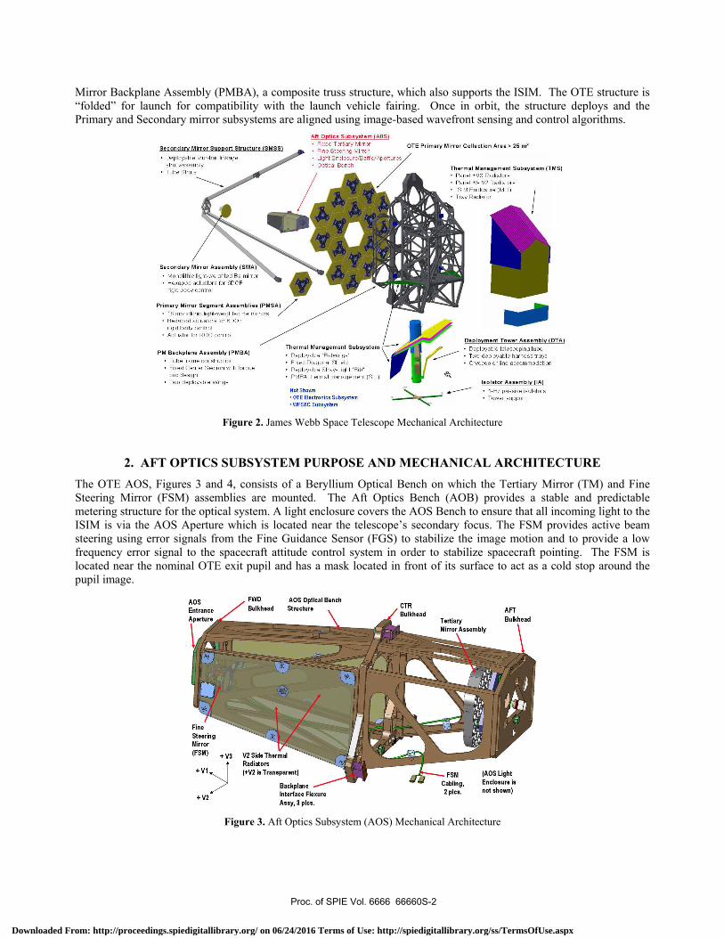
The OTE AOS, Figures 3 and 4, consists of a Beryllium Optical Bench on which the Tertiary Mirror (TM) and Fine Steering Mirror (FSM) assemblies are mounted. The Aft Optics Bench (AOB) provides a stable and predictable metering structure for the optical system. A light enclosure covers the AOS Bench to ensure that all incoming light to the ISIM is via the AOS Aperture which is located near the telescope’s secondary focus. The FSM provides active beam steering using error signals from the Fine Guidance Sensor (FGS) to stabilize the image motion and to provide a low frequency error signal to the spacecraft attitude control system in order to stabilize spacecraft pointing. The FSM is located near the nominal OTE exit pupil and has a mask located in front of its surface to act as a cold stop around the pupil image.
Figure 3. Aft Optics Subsystem (AOS) Mechanical Architecture
Proc. of SPIE Vol. 6666 66660S-2
Downloaded From: http://proceedings.spiedigitallibrary.org/ on 06/24/2016 Terms of Use: http://spiedigitallibrary.org/ss/TermsOfUse.aspx
Tertiary Mirror Assembly (TMA)AOS
Entrance
Aperture
\
Incoming Light FromSecondary Fine Steering MirrorMirror (FSM) & Mask
AOS Exit: Light To ScienceInstruments
AOS Mounted in OlE
Cross Section Detail Viewof AOS to PMBA Interface
Flexure System
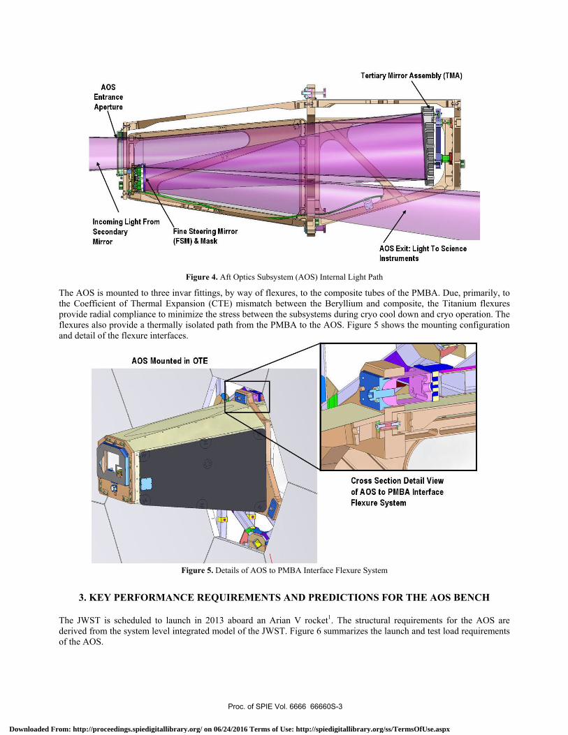
Figure 4. Aft Optics Subsystem (AOS) Internal Light Path
The AOS is mounted to three invar fittings, by way of flexures, to the composite tubes of the PMBA. Due, primarily, to the Coefficient of Thermal Expansion (CTE) mismatch between the Beryllium and composite, the Titanium flexures provide radial compliance to minimize the stress between the subsystems during cryo cool down and cryo operation. The flexures also provide a thermally isolated path from the PMBA to the AOS. Figure 5 shows the mounting configuration and detail of the flexure interfaces.
Figure 5. Details of AOS to PMBA Interface Flexure System
3. KEY PERFORMANCE REQUIREMENTS AND PREDICTIONS FOR THE AOS BENCH
The JWST is scheduled to launch in 2013 aboard an Arian V rocket1. The structural requirements for the AOS are derived from the system level integrated model of the JWST. Figure 6 summarizes the launch and test load requirements of the AOS.
Proc. of SPIE Vol. 6666 66660S-3
Downloaded From: http://proceedings.spiedigitallibrary.org/ on 06/24/2016 Terms of Use: http://spiedigitallibrary.org/ss/TermsOfUse.aspx

Description Requirement PredictedPerformance
Launch Loads —9g VIN2 plane—10 gV3 dir
Axial load is combined withlateral load in any lateral direction
Meets
Test Loads —Il g lateral (any direction in
V2N3 plane)
hg axial (VI direction)
Meets
AcousticEnvironment
Acceptance —142 dB overall
Protoflight —146 dB
Meets
Backplane rackingdisplacements
Max T1,fl, RI, R2, R3 Meets
Random Vibration Protoflight —5 Grms
Acceptance —4 GrmsMeets (1BR)
Mechanical Shock Low shock environment Test at higher
assembly
Natural Frequency 25 Hz. (TBR) Meets
Survival
Temperature Range
25K to 323K (TBR) Meets
Cyclical Loading
Fatigue Analysis
Evaluate tbr ground loads,testing, and launch environments.
Meets (1BR)
Dynamic envelope c 5.0 mm (sub-allocation) Meets
First ModeTilt about V3
a
Thermal gradientsacross AOS <O.5°K,with radiators
i)—
Figure 6. AOS Structural Requirements
Unlike the PMSA and SMA, the Tertiary Mirror position and shape cannot be actuated. The AOS Bench must provide a stable metering structure for the telescope optical system to function within its error budget. A changing thermal environment at the higher system level interface and gradients developed in the structure can affect this stability. There are two driving thermal requirements for the AOS. First, the AOS must meet its operational requirements while exposed to a 30 to 45K temperature environment. This requirement would be difficult to meet for many materials due to the CTE and/or lay-up sensitivity over the 15K range. The second requirement is that the AOS must maintain the FSM at ≤ 40K. This requirement drives the design to a passively cooled radiator system supported by the AOS Bench. Supporting a cooling source such as this does not introduce significant gradients in the structure due to the high thermal conductivity of Beryllium at cryo temperatures. Additionally, predicting thermal conductance across joints for the Beryllium structure will have less uncertainty than other types of space structures because the large quantity of fasteners between the Beryllium panels will behave like other stiff metal-to-metal interfaces. The contour in Figure 7 shows that the predicted thermal gradients across the AOS bench to be < .5K while supporting the radiators and being attached at the flexures to a warmer backplane interface.
Figure 7. AOS Thermal Gradients Profile
Proc. of SPIE Vol. 6666 66660S-4
Downloaded From: http://proceedings.spiedigitallibrary.org/ on 06/24/2016 Terms of Use: http://spiedigitallibrary.org/ss/TermsOfUse.aspx

Description Requirement PredictedPerformance
TMA to AOB Interface Alignment
StabilityThe change in location of the TMA to AOBintefface relative to the AOB to PMBAinteilace due to the temperature changebetween the cold pointing and hot pointingenvironments
Despace c 80 nm Meets
Decenter c 20 nm Meets
Tiltc3Onrad Meets
Clocking c 60nrad
Meets
FSM to AOB Interface Alignment
StabilityThe change in location of the FSM to AOBinteilace relative to the AOB to PMBAinteilace due to the temperature changebetween the cold pointing and hot pointingenvironments
Despace c 110 nm Meets
Decenter c 80 nm Meets
TiltclOnrad Meets
Clocking c 90nrad
AOB design (nominal CTE) meets therequirements for TMA and FSMalignment stability.
Hot to Cold PointingDisplacements Profile of Structure(No external radiators shown)
As the base optical reference for the rest of the system, the AOS Bench is required to maintain the alignment of the Tertiary and Fine Steering mirrors relative to each other and to the telescope. In fact, the AOS Bench must bear a suite of requirements that assure its operational stability over a 14 day period. Separately, the Primary and Secondary mirrors are adjusted via wavefront sensing and control to the AOS system. The concept of operations for JWST calls for only adjusting the primary and secondary mirrors every 14 days in order to maximize observing efficiency. Therefore the requirements are designed to limit the wavefront drift such that science images are not degraded during the 14 days period between wavefront sensing and control updates. Because Beryllium has such good physical characteristics (i.e. CTE) at operational temperatures (30-45K) we easily meet the alignment stability requirements for the small predicted change in temperature over 14 days. Figure 8 summarizes the AOS Bench alignment stability requirements.
Figure 8. AOS Operational Stability Requirements
4. BERYLLIUM OPTICAL BENCH DESIGN
During the preliminary design phase of the AOS Bench significant emphasis was placed on identifying and implementing the best material to meet the specified performance requirements of the AOS Bench. Structural grade Beryllium had been previously been chosen by BATC for the PMSA and SMA Delta Frame structures. So, a Beryllium design would build on PMSA and SMA design and fabrication heritage already established by BATC. A Beryllium AOB would also provide a material match to the Beryllium optics which would simplify the optic mount design and move the material transition from composite to Beryllium out to the PMBA interface, where it could be more effectively isolated from the optics. A primary benefit for Beryllium was its superior Hot to Cold pointing stability which was well understood and characterized by the JWST program. BATC had also established mature material data heritage for JWST which meant no additional material testing and development was required. BATC also identified several programmatic benefits including the utilization of the existing BATC beryllium design team. In addition, the cost and schedule risks associated with the Beryllium design were well understood based upon PMSA and SMA production efforts, and the existing subcontract management functions and technical oversight were already in place at BATC. Ultimately, BATC chose to design the AOS Bench using S-200-FH (structural grade) Beryllium2.
Proc. of SPIE Vol. 6666 66660S-5
Downloaded From: http://proceedings.spiedigitallibrary.org/ on 06/24/2016 Terms of Use: http://spiedigitallibrary.org/ss/TermsOfUse.aspx
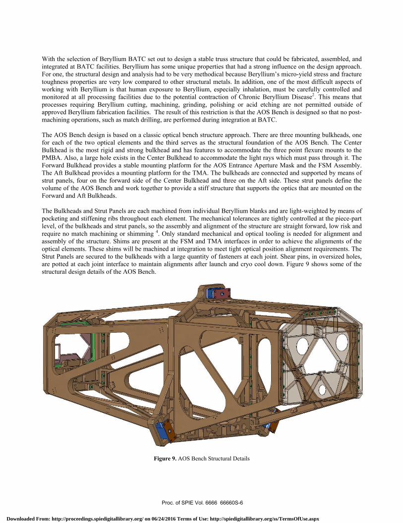
With the selection of Beryllium BATC set out to design a stable truss structure that could be fabricated, assembled, and integrated at BATC facilities. Beryllium has some unique properties that had a strong influence on the design approach. For one, the structural design and analysis had to be very methodical because Beryllium’s micro-yield stress and fracture toughness properties are very low compared to other structural metals. In addition, one of the most difficult aspects of working with Beryllium is that human exposure to Beryllium, especially inhalation, must be carefully controlled and monitored at all processing facilities due to the potential contraction of Chronic Beryllium Disease2. This means that processes requiring Beryllium cutting, machining, grinding, polishing or acid etching are not permitted outside of approved Beryllium fabrication facilities. The result of this restriction is that the AOS Bench is designed so that no post-machining operations, such as match drilling, are performed during integration at BATC. The AOS Bench design is based on a classic optical bench structure approach. There are three mounting bulkheads, one for each of the two optical elements and the third serves as the structural foundation of the AOS Bench. The Center Bulkhead is the most rigid and strong bulkhead and has features to accommodate the three point flexure mounts to the PMBA. Also, a large hole exists in the Center Bulkhead to accommodate the light rays which must pass through it. The Forward Bulkhead provides a stable mounting platform for the AOS Entrance Aperture Mask and the FSM Assembly. The Aft Bulkhead provides a mounting platform for the TMA. The bulkheads are connected and supported by means of strut panels, four on the forward side of the Center Bulkhead and three on the Aft side. These strut panels define the volume of the AOS Bench and work together to provide a stiff structure that supports the optics that are mounted on the Forward and Aft Bulkheads. The Bulkheads and Strut Panels are each machined from individual Beryllium blanks and are light-weighted by means of pocketing and stiffening ribs throughout each element. The mechanical tolerances are tightly controlled at the piece-part level, of the bulkheads and strut panels, so the assembly and alignment of the structure are straight forward, low risk and require no match machining or shimming 4. Only standard mechanical and optical tooling is needed for alignment and assembly of the structure. Shims are present at the FSM and TMA interfaces in order to achieve the alignments of the optical elements. These shims will be machined at integration to meet tight optical position alignment requirements. The Strut Panels are secured to the bulkheads with a large quantity of fasteners at each joint. Shear pins, in oversized holes, are potted at each joint interface to maintain alignments after launch and cryo cool down. Figure 9 shows some of the structural design details of the AOS Bench.
Figure 9. AOS Bench Structural Details
Proc. of SPIE Vol. 6666 66660S-6
Downloaded From: http://proceedings.spiedigitallibrary.org/ on 06/24/2016 Terms of Use: http://spiedigitallibrary.org/ss/TermsOfUse.aspx

Hot and cold temperature profiles show temperature gradient <O.5°K of structure (no external radiators shown)
!hi
5. BENEFITS OF BERYLLIUM TO MEET KEY CRYOGENIC PERFORMANCE REQUIREMENTS OF THE AOS
There are several key reasons that S-200-FH Beryllium was chosen as the material to fabricate the AOS Bench. Most of these reasons have been previously described in Section 4. For the AOS, Beryllium’s favorable properties at the cryogenic operating environment are a key to meeting its requirements. The tightly controlled process by which Beryllium is created contributes greatly to its useful mechanical properties. The process starts when raw Beryllium is mined from the ground and refined into a powder form. The powder is then poured into a specially designed steel, HIP (Hot Isostatic Press), can which is in the oversized shape of the solid blank that needs to be produced. The HIP process utilizes heat and pressure to compress the powder into an extremely isotropic solid metal. The steel can is then chemically etched away from the solid Beryllium blank which is then ready to machine, using conventional machining methods 3. Each Strut Panel and Bulkhead of the AOS Bench will be fabricated from its own Beryllium blank. The end result is a Beryllium part that not only has a high strength to weight ratio, but is also non-magnetic and has very high thermal and electrical conductivity. The thermal conductivity and CTE at cryogenic temperatures are the key reasons that the AOS can meet its alignment stability requirements during operation 2. Over the operating temperature range of the AOB, the extremely low CTE and extremely high thermal conductivity for Beryllium result in nearly zero thermal deformation of the structure. During the Hot-to-Cold pointing scenario of the telescope, the AOS Bench sees less than 0.5 K gradients across the structure and can tolerate relatively large temperature swings while maintaining alignment. Figure 10 shows the temperature map across the AOS Bench for the Hot (left) and Cold (right) environments. The profiles are nearly identical.
Figure 10. Hot and Cold Pointing Thermal Gradients on AOS Bench
There are several other good thermal properties of Beryllium that merit mentioning. At cryogenic temperatures, the Cp (thermal capacitance) of Beryllium is on the same order as the material of the PMBA to which the AOS is mounted. Also, the thermal time constant is about the same as the PMBA material. As a result of these properties no special thermal treatment, such as a surface finish or MLI, is needed in the AOS design. In addition, the Beryllium-to-Beryllium joints can be treated like any bolted metal-to-metal interface because the thermal resistance across the bolted joints is not a driving issue. The JWST program has invested significant time and resources characterizing structural and thermal the properties of materials that are used on the program. Beryllium S200FH has been characterized at ambient and cryogenic temperatures for JWST. The JWST program has tested and verified the values for strength allowables, Modulus, fracture toughness, micro-yield tensile stress and Coefficient of Thermal Expansion (CTE). These values are used in the thermal and structural analysis databases for design verification.
Proc. of SPIE Vol. 6666 66660S-7
Downloaded From: http://proceedings.spiedigitallibrary.org/ on 06/24/2016 Terms of Use: http://spiedigitallibrary.org/ss/TermsOfUse.aspx

— — Allowable Despace CTh
Tern perature(K)
ii.ii_______nuowarnTilt CTh
34 38 14P: 42 44
——X-293X-2l8
>(-I 77
Y-21 I
178
——Y-294—t—y-45
Z-212
Z-179
Z-295
Because of the tight alignment stability requirements, BATC has conducted further analysis in order to characterize the material variability of S-200-FH Beryllium. Numerous samples, in three axial directions, have been tested and characterized by Brush Wellman Engineered Materials and BATC. The analysis shows that the lot-to-lot CTE variability of Beryllium is very low and well within the requirements for the AOS optical alignment stabilities. Figure 11 shows the strain plots of several Beryllium samples, near the operating temperature. These results show predictable and low variability between samples, regardless of test direction.
Figure 11. Material Variability is Low and Predictable
6. CONCLUSION
The James Webb Space Telescope Aft Optics Subsystem Bench design is tailored to meet the specific requirements of the telescope system. The L2 solar orbit provides a cryogenic environment to optimize the performance of the infrared tuned telescope 1. In order to meet the strict optical requirements, Beryllium has been selected as the most appropriate material for the optical bench structure. The AOS Bench is designed with the influence of the driving requirements and unique properties, characteristics and qualities of the Beryllium material. Preliminary predictions show that the AOS Bench meets all of its launch loads, thermal environment, thermal performance and alignment stability requirements. BATC is proceeding with detailed design and fabrication of the AOS Bench in order to meet a launch schedule of 2013 for the James Webb Space Telescope.
7. ACKNOWLEDGEMENTS
The BATC JWST design and production team gratefully acknowledges the many contributions of Beryllium team partners Brush Wellman Engineered Materials, provider of Beryllium material, and Axsys Technologies, precision fabrication of JWST Beryllium piece-parts, for the development of the AOS Bench.
8. REFERENCES
1. Official JWST Website: www.jwst.nasa.gov 2. Brush Wellman Engineered Materials Website: www.berylliumproducts.com 3. Bodycote International PLC Website: www.bodycote.com 4. Axsys Technologies Website: www.axsys.com
Proc. of SPIE Vol. 6666 66660S-8
Downloaded From: http://proceedings.spiedigitallibrary.org/ on 06/24/2016 Terms of Use: http://spiedigitallibrary.org/ss/TermsOfUse.aspx