Embed Size (px)
Citation preview
NASA SP-5932 (01)
TECHNOLOGY UTlCLJlZATllQN I , I 1 . 8 1 ' 1 8
1 ' 1 . I !- I .., I . I 0 t t
CRYOGENICS
CASE F co33-r
A COMPILATION
I NATIONAL AERONAUTICS A N D SPACE ADMINIST-RATION
https://ntrs.nasa.gov/search.jsp?R=19710021231 2018-06-02T00:22:25+00:00Z
CRYOGENICS
A COMPILATION
TECHNOLOGY UTILIZATION OFFICE 1970
NATIONAL AERONAUTICS AND SPACE ADMINISTRATION Washington, D.C,
NOTICE * This docunlellt was prepared under the sponsorship of the National Aeronautics and Space Administration. Neither the United States Gorernnient nor any person acting on behalf of the United States Government assumes any liability resulting from the use of the information contained in this docuuient, or war ra~l t s that such use will be free from privately owned rights.
For sale by the National Technical Information Service, Springfield, Virginia 22151 -Price $1.00
Foreword
The National Aeronautics and Space Administration and Atomic Energy Corn- mission have established a Technology Utilization Program for the dissemination of information on technological developments which have potential utility outside the aerospace and nuclear communities. By encouraging multiple application of the results of their research and development, NASA and AEC earn for the public an increased return on the investment in aerospace and nuclear research and de- velop ment programs.
This publication is part of a series intended to provide such technical ir forma- tion. A selection has been made of items pertaining to cryogenic technology. Ap- plications range from cyrogenically cooled masers to a method of expediting pipe repair by freezing outer boundary sections. Materials and devices are discussed in terms of durability and reliability under extreme temperature stresses.
Additional technical information on individual devices and techniques can be requested by circling the appropriate number on the Reader's Service Card included in this compilation.
Unless otherwise stated, NASA and AEC contemplate no action on the tech- nology described.
We appreciate comment by readers and welcome hearing about the relevance and utility of the information in this compilation.
Ronald J . Philips, Director Techtrology Utilizatio~r Office National Aero~rautic.~ atrd Space Adtni~ri.~tratioi
iii
Contents
SECTION 1 . Materials Page
Evaluation of a Fluorocarbon Plastic Used . . . . . . . . . . . . . . . . . . . . . . . . . . . . . . . . . . . in Cryogenic Valve Seals 1
Fiberglass Prevents Cracking of Polyurethane . . . . . . . . . . . . . . . . . . . . . . Foam Insulation on Cryogenic Vessels .I
. . . . . . . . . . . . . . Panelized High Performance Multilayer Insulation 2 Physical Stability Testing of Cryogenic Tank
. . . . . . . . . . . . . . . . . . . . . . . . . . . . . . . . . . . . . . . . . . . . . . . Insulation 2 . . . . . . . . . . . . . . . . . . . . . . . Thermal Expansion Properties of Fluids 2
. . . . . . . . . . . . . . . . . . . . Fiberglass-Reinforced Structural . Materials 3
SECTION 2 . New and Improved Devices . . . . . . . . . . . . . . . . . . . . . Cryogenic Liquid Level Measuring Probe 3
silicon Strain Sensors for Pressure Measurement . . . . . . . . . . . . . . . . . . . . . . . . . . . . . . . . at Cryogenic Temperatures 4
Superconductive Thin Film Used as Liquid Helium Level Sensor . . . . . . . . . . . . . . . . . . . . . . . . . . . . . . . . . . . . . . . . . . . . 4
Superconducting Switch Permits Measurements of Small . . . . . . . . . . . . . . . . . . . . . . . . Voltages at Cryogenic Temperatures 5
. . . . . . . . . . . . . . . . . . . . . . . . . . . . . . . . . . . . . . . Coaxial Sensing Line 5 . . . . . . . . . . . . . . . . . . . . . . . . . . Cryogenic Hardness Testing Device 6
. . . . . . . . . . . . . . . . . . . . . . . . . . . . . . . . . . . . . Cryogenic Feedthrough 6 Electromechanical Rotary Actuator Operates Over Wide
Temperature Range . . . . . . . . . . . . . . . . . . . . . . . . . . . . . . . . . . . . . . 7 . . . . . . . . . . . . . . . . . . . . . . . . . . A Liquid Hydrogen Inlet Distributor 7
Strain Gage Wire Feedthrough for Cryogenic . . . . . . . . . . . . . . . . . . . . . . . . . . . . . . . . . . . . . . . . . . Pressure Vessels 8
Elimination of Surging Flow Characteristics in Liquid Oxygen . . . . . . . . . . . . . . . . . . . . . . . . . . . . . . . . . . . . . . . . 8
Cryogenic Container Thermodynamics During . . . . . . . . . . . . . . . . . . . . . . . . . . . . . . . . . . . . . . . Propellant Transfer 8
. . . . . . . . . . . . . . . . . . . . Liquid Hydrogen Storage Vessel Warm-up 9
SECTION 3 . Applications . . . . . . . . . . . . . . . . . . . . . . . . . . . . . . . . . . . . . . . . . . . . . . Freeze Block 9
Thermal Short Improves Sensitivity of Cryogenically . . . . . . . . . . . . . . . . . . . . . . . . . . . . . . . . . . . . . . . . . . Cooled Maser 10
. . . . . . . . . . . . . . . . . . . . . . Dual-Purpose Chamber Cooling System 10
Section 1. Materials
EVALUATION O F A FLUOROCARBON PLASTIC USED I N CRYOGENIC VALVE S E A L S
Tests were conducted to determine the inde- pendent and interacting effects of strain rate, tem- perature, crystallinity, and surface finish (smooth- ness) on the tensile strength of a commercial chiorotrifluoroethylene plastic (CFTE) used for lipseals in very fast-acting liquid oxygen valves. Approximately 200 tests were performed at strain rates between 0.02 and 10,000 inches per minute and temperatures of 75" and -320°F. Em- phasis was placed on obtaining mechanical prop- erty data over a wide range of strain rates at cryo- genic temperatures to determine if the effects of crystallinity and surface smoothness are greater at high strain rates than at low and medium strain rates.
The analysis showed that the environmental factors (temperature and strain rate) were more significant than the material properties (surface
finish and crystallinity). Effects of high straln rate on tensile strength differed for ambient (75°F) and cryogenic temperature (-320°F). The speci- mens appeared to fail in a two-step process at a strain rate of 10,000 inches per minute. ~Fsom the accumulated data, however, it ?a as concluded that machined medium-crystallinity seals can be used as a less expensive replacement for rnoIded low-crystallinity seals in fast-acting c-yogenlc ficnid valves.
Source: R. E. Cierniak, J H. Lleb, and R. E. Mowers of
North American Rockwell Corp. under contract to
Marshall Space Flight Center (MFS-1x189)
Circle I 011 Reader's Service Card.
FIBERGLASS PREVENTS CRACKING O F POLYURETHANE FOAM I[NSUL,iTION O N CRYOGENIC VESSELS
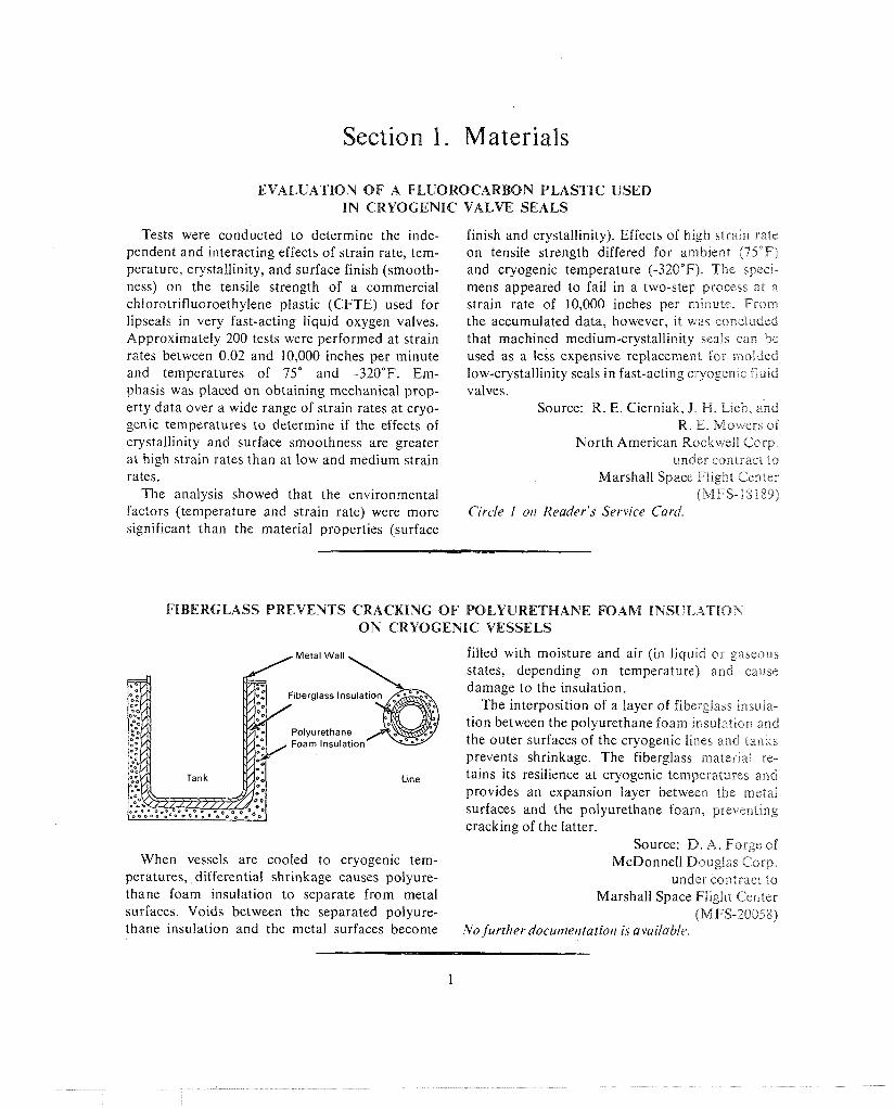
filled with moisture and air (in liquid or gaseous states, depending on temperature) and cause
F~berglass lnsulat~ damage to the insulation.
The interposition of a layer of fibe~glass ~nsula- tion between the polyurethane foam insulataon and
Foam lnsulat~on the outer surfaces of the cryogenic lines and tanks prevents shrinkage. The fiberglass material re-
L~ne tains its resilience at cryogenic temperatures and provides an expansion layer between the metal surfaces and the polyurethane foam, preventing cracking of the latter.
Source: D. A. Forge of When vessels are cooled to cryogenic tern- McDonnell Douglas Corp.
peratures, differential shrinkage causes polyure- under contract to thane foam insulation to separate from metal Marshall Space Fllghe Center surfaces. Voids between the separated polyure- (MFS-20058) thane insulation and the metal surfaces become No furtherdocutzentatio/r is available.
CRYOGENICS
PANELIZED H I G H P E R F O R M A N C E MULTILAYER INSULATION
f\ cornpo:iite insulation covering possessing desirable cryogenic insulation properties, venting characteristics, and high energy particle absorption qualities, is available for cryogenic-fluids storage tanks and mobile tankers. This multilayer cover- ing has low conductivity foam spacers interleaved between layers of aluminized 114-mil polymer film radiation shields. It is faced with a high density jacket which is resistant to penetration damage.
Source: R. A. Burkley and C. B. Shriver of Goodyear Aerospace Corp.
under contract to Marshall Space Flight Center
and J. M. Stuckey Marshall Space Flight Center
(MFS-14023) Circle 2 0 1 1 Reader's Service Card.
PHYSICAL STABILITY TESTING O F CRYOGENIC TANK INSULATION
Ala inexpensive testing procedure has been de- veloped for r he evaluation of potential cryogenic ~nsulation composites by both manufacturers and userx.
Histor~cally, the physical stability of cryogenic vessel insulation has been a serious problem. Insu- lation liners used on liquid hydrogen tanks are required to ~{ithstand considerable stresses from thermal chocks imparted to the insulation during the Ir!Pang and draining of tanks. To determine the effects of these stresses, the test cyclically subjects the specimens to thermal shock so that the damage can be measured.
Speclinens of the insulation composite to be tested are bonded to plates of a metal having a very low coefficient of thermal expansion. The re-
sultant units are then immersed in a cryostat con- taining liquid hydrogen for approximately 5 min- utes, removed, and kept at room temperature for at least 5 minutes. This procedure of thermally shocking the specimens is repeated for 10 cycles. The number of cracks and the extent of damage on the insulation composites are visually observed and recorded at the end of each cycle for further analysis of the test results.
Source: D. Rossello of McDonnell Douglas Corp.
under contract to Marshall Space Flight Center
(MFS- 12547) Circle 3 0 1 1 Reader's Service Card.
T H E R M A L EXPANSION P R O P E R T I E S O F FLUIDS
The lherllldl expansion properties of fluids have bee11 compa1i:d into a single handbook. Thermal expan\lon v~ temperature curves for fluids from
423"l- to 20100°F are presented in two sections, oile covering cryogenic temperatures (down to 4 2 3 " F ) , dnrl the other dealing with elevated temperature\ to 2000°F. The curves are intended ti: s ~ ~ p p l e n ~ e l ~ t the accuracy of computations using I~ile~lr t h e m 11 expansion coefficients by permit\- tiilg the direct determination of the total thermal
length change between any two specific tempera- tures. Descriptions of test procedures and analyses of the measurements are also included in the handbook.
Source: E. F. Green of North American Rockwell Corp.
under contract to Marshall Space Flight Center
(MFS-18335) Circle 4 O I I Rearler ' .~ Service Card.
MATERIALS 3
FIBERGLASS-REINFORCED STRUCTURAL MATERIALS
Properties of fiberglass-reinforced plastic ma- terials with potential application as tension sup- ports for cryogenic tanks have been extensively investigated. These materials are of particular interest because of their low density, unidirec- tional strength, low thermal conductivity, and ease of fabrication. Tension rods, tubular struts, and "I" beams manufactured from epoxy resins with fiberglass reinforcements were evaluated and compared with their metallic counterparts to de- termine the thermal and weight advantages of using fibergla-ss-reinforced plastic structures. Beams were considered as payload support mem- bers where lightweight rather than low thermal conductivity was of primary importance. It was
found that deflections are greater and stiffness less for fiberglass materials than for comparable metallic parts.
Therefore, in cases where stiffness design cri- teria prevail and thermal conductivity is 11ot a factor, advanced composites employing filament- ary materials bonded with epoxy resins may be competitive with metallic materials.
Source: D. 14. Barliett of Tl?e Boeing Co.
undt:r contract to Marshall Space Flight Center
(M FS- 14806) Circle 5 017 Reader's Service Card.
Section 2. New and Improved Devices
CRYOGENIC LIQUID LEVEL MEASURING PROBE
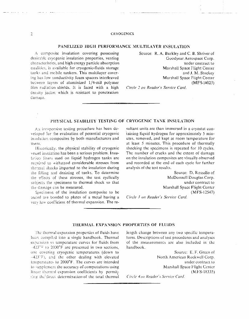
Static and dynamic levels of cryogenic liquids measures the difference in the dielectric constants in a hydrogen bubble chamber can be measured between the liquid and gas phases of the mcdra. by a newly developed universal liquid level meas- The probe capacity is therefore a function of the uring probe. This device incorporates a unique height of the liquid within the probe elements.
The e robe and its associated cable constitute the
Outer Probe Element
Inner Probe Element
capacity in the tuned circuit of an oscillator, and a liquid level change is reflected as , ln oscillator frequency change. A voltage controlled osc~llator is phase locked to the probe oscillator frequency. The error voltage required to keep the two oscil- lators phase-locked is then a function of the liquid level.
A percentage readout is used with ihe probe to provide more efficient use of the instrument's dynamic range and to reduce operator error. In
frequency discriminator to provide continuous addition, the system may be used as a data logger readings of the levels of nitrogen, hydrogen, or to record liquid levels in a number o f containers helium to an accuracy of + I % . The probe has through a scanning operation. a dynamic response time of less than 150 ,usec, Source: J. A. Dinkel and C. R. Wegner allowing boiling conditions or other turbulence to Argonne National Laboratory be observed throughout all the transition stages. (iaRG- 10 t 38)
The coaxial probe, when immersed in a liquid, Circle 6 on Reader's Service Card.
CRYOGENICS
SILICON STRAIN SENSORS FOR PRESSURE MEASUREMENT AT CRYOGENIC TEMPERATURES
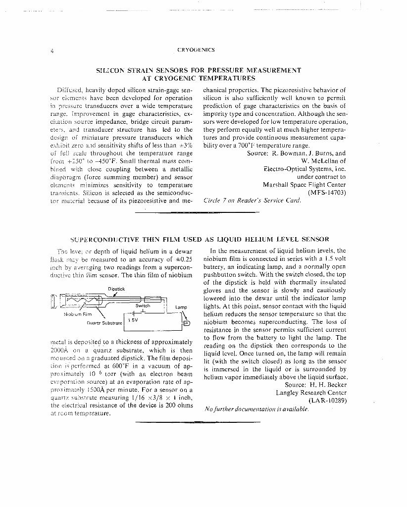
Diffused, hleavily doped silicon strain-gage sen- sor eiemenis have been developed for operation in pressure transducers over a wide temperature range. Improvement in gage characteristics, ex- citation source impedance, bridge circuit param- eters, and transducer structure has led to the design of miniature pressure transducers which exhibit zero and sensitivity shifts of less than *3% of f ~ i l i scale throughout the temperature range from t250" LO 4 5 0 ° F . Small thermal mass com- Sincd with close coupling between a metallic diaphragm (force summing member) and sensor elerne~ats minimizes sensitivity to temperature transients. Silicon is selected as the semiconduc- tor rniiteriai because of its piezoresistive and me-
chanical properties. The piezoresistive behavior of silicon is also sufficiently well known to permit prediction of gage characteristics on the basis of impurity type and concentration. Although the sen- sors were developed for low temperature operation, they perform equally well at much higher tempera- tures and provide continuous measurement capa- bility over a 700°F temperature range.
Source: R. Bowman, J. Burns, and W. McLellan of
Electro-Optical Systems, Inc. under contract to
Marshall Space Flight Center (M FS- 14703)
Circle 7 on Reader's Service Card.
SUPERCONDUCTIVE THIN FILM USED AS LIQUID HELIUM LEVEL SENSOR
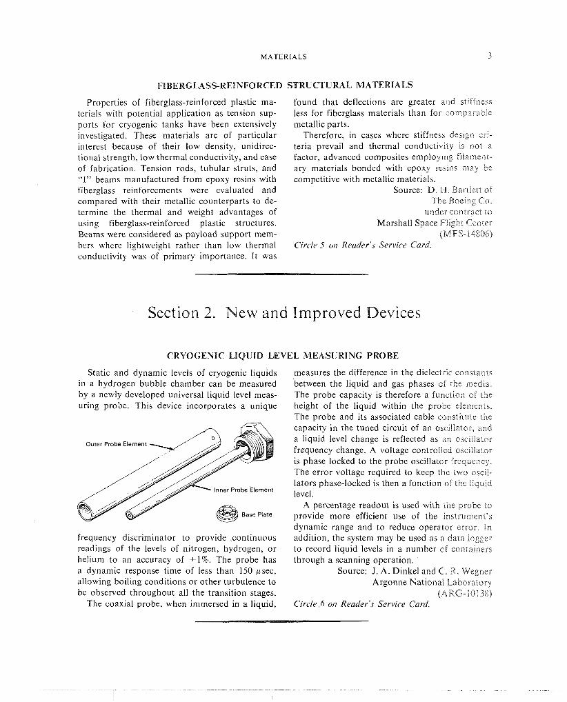
The level cr depth of liquid helium in a dewar f1a.k may be measured to an accuracy of 10.25 unch by avereging two readings from a supercon- ductive thin film sensor. The thin film of niobium
Diostick
r L Lamp
Niobium Filiri
Cluartz Substrate
metal ns depo ,~ted to a thickness of approximately 2009.A on a quartz substrate, which is then 111ounted on a graduated dipstick. The film deposi- lion s performed at 600°F in a vacuum of ap- proxirndtcly 10-6 torr (with an electron beam evapordl~on source) at an evaporation rate of ap- prox~n~~itcly 1500A per minute. For a sensor on a quartz iubs t r~ te meacuring 1/16 x3/8 x 1 inch, the electr~cal resistance of the device is 200 ohms dl room tempxature.
In the measurement of liquid helium levels, the niobium film is connected in series with a 1.5 volt battery, an indicating lamp, and a normally open pushbutton switch. With the switch closed, the top of the dipstick is held with thermally insulated gloves and the sensor is slowly and cautiously lowered into the dewar until the indicator lamp lights. At this point, sensor contact with the liquid helium reduces the sensor temperature so that the niobium becomes superconducting. The loss of resistance in the sensor permits sufficient current to flow from the battery to light the lamp. The reading on the dipstick then corresponds to the liquid level. Once turned on, the lamp will remain lit (with the switch closed) as long as the sensor is immersed in the liquid or is surrounded by helium vapor immediately above the liquid surface.
Source: H. H. Becker Langley Research Center
(LAR- 10289) No further d o c u m e ~ ~ t a t i o ~ ~ is available.
NEW A N D IMPROVED DEVICES 5
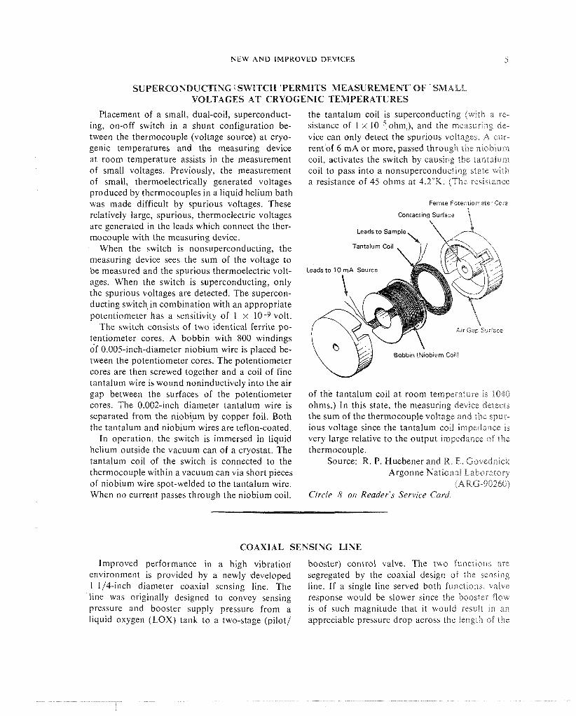
SUPERCONDUCTING .SWITCH 'PERMITS MEASUREMENT' OF 'SMALL VOLTAGES AT CRYOGENIC TEMPERATURES
Placement of a small, dual-coil, superconduct- ing, on-off switch in a shunt configuration be- tween the thermocouple (voltage source) at cryo- genic temperatures and the measuring device at room temperature assists in the measurement of small voltages. Previously, the measurement of small, thermoelectrically generated voltages produced by thermocouples in a liquid helium bath was made difficult by spurious voltages. These relatively large, spurious, thermoelectric voltages are generated in the leads which connect the ther- mocouple with the measuring device.
When the switch is nonsuperconducting, the measuring device sees the sum of the voltage to be measured and the spurious thermoelectric volt- ages. When the switch is superconducting, only the spurious voltages are detected. The supercon- ducting switch in combination with an appropriate potentiometer has a sensitivity of 1 x 10 -9 volt.
The switch consists of two identical ferrite po- tentiometer cores. A bobbin with 800 windings of 0.005-inch-diameter niobium wire is placed be- tween the potentiometer cores. The potentiometer cores are then screwed together and a coil of fine tantalum wire is wound noninductively into the air gap between the surfaces of the potentiometer cores. The 0.002-inch diameter tantalum wire is separated from the niobium by copper foil. Both the tantalum and niobium wires are teflon-coated.
In operation, the switch is immersed in liquid helium outside the vacuum can of a cryostat. The tantalum coil of the switch is connected to the thermocouple within a vacuum can via short pieces of niobium wire spot-welded to the tantalum wire. When no current passes through the niobium coil,
the tantalum coil is superconducting ( w ~ t l ~ a re- sistance of 1 x 10 ohm,), and the rneasurlng de- vice can only detect the spurious voltages. A cur- rent of 6 mA or more, passed through the niobium coil, activates the switch by causing the tantalum coil to pass into a nonsuperconduc"Linp state with a resistance of 45 ohms at 4.2OK. (The resiclance
Ferrite Potentiometer Core
Contacting Surface \ Leads to Sample
Tantalum Coil
of the tantalum coil at room temperature is 1040 ohms.) In this state, the measuring device detects the sum of the thermocouple voltage and thc spur- ious voltage since the tantalum coil impedance is very large relative to the output impedance of the thermocouple.
Source: R. P. Huebener and R. E. Govednick Argonne National Laboratory
(A RG-90260) Circle 8 on Reader's Service Card
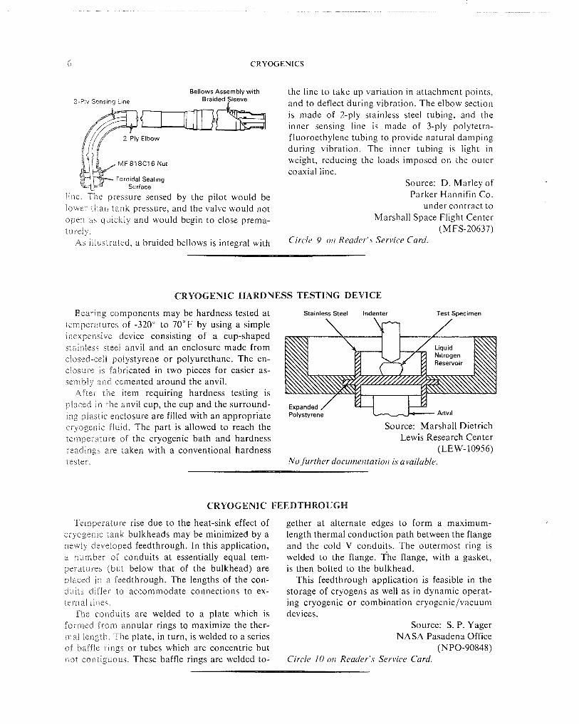
COAXIAL SENSING LINE
Improved performance in a high vibration booster) control valve. The two fu~?ct~oir i are environment is provided by a newly developed segregated by the coaxial design of the sencing 1 114-inch diameter coaxial sensing line. The line. If a single line served both functior~s, valve line was originally designed to convey sensing response would be slower since the booster flow pressure and booster supply pressure from a is of such magnitude that it would result 111 a11 liquid oxygen (LOX) tank to a two-stage (pilot/ appreciable pressure drop across the length of the
5 CRYOGENICS
Bellows Assembly with
3-F'iy Sens~ng L~ne Braided Sleeve
MF818C16 Nut
line file prej\ui-e sensed by the pdot would be lower ~ h d n t d n k pressure, and the valve would not open #I\ qulcI<iy and would begin to close prema- turely As ilidserated, a braided bellows is integral with
the line to take up variation in attachment points, and to deflect during vibration. The elbow section is made of 2-ply stainless steel tubing, and the inner sensing line is made of 3-ply polytetra- fluoroethylene tubing to provide natural damping during vibration. The inner tubing is light in weight, reducing the loads imposed on the outer coaxial line.
Source: D. Marley of Parker Hannifin Co.
under contract to Marshall Space Flight Center
(M FS-20637) Circle 9 011 Reader's Service Card.
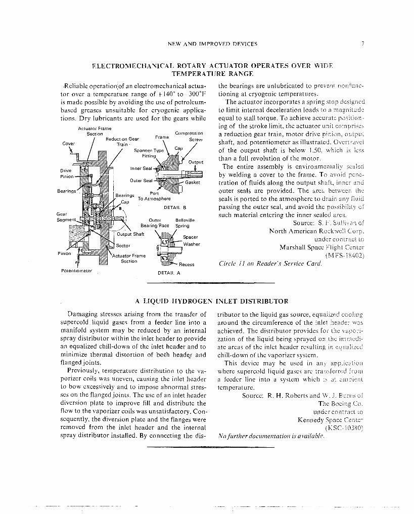
CRYOGENIC HARDNESS TESTING DEVICE
Bearing components may be hardness tested at temperatures of -320" to 70°F by using a simple inexpensive device consisting of a cup-shaped stainless steel anvil and an enclosure made from closed-cell polystyrene or polyurethane. The en- closure is fabricated in two pieces for easier as- sembly and cemented around the anvil.
After the item requiring hardness testing is placed in the anvil cup, the cup and the surround- ing plastic enclosure are filled with an appropriate cryegenic fluid. The part is allowed to reach the temperature of the cryogenic bath and hardness readings are taken with a conventional hardness tester.
Stainless Steel Indenter Test Specimen
/ h\\\ I I / Liauid h\\N
Expanded / Polystyrene Anvil
Source: Marshall Dietrich Lewis Research Center
(LEW-10956) No further docume11tatio/r is available.
CRYOGENIC FEEDTHROUGH
Temperature rise due to the heat-sink effect of cryogenic tank bulkheads may be minimized by a newly developed feedthrough. In this application, a number of conduits at essentially equal tem- peratures (but below that of the bulkhead) are placed in a feedthrough. The lengths of the con- duits differ to accommodate connections to ex- icrila! lines.
The conduits are welded to a plate which is formed from annular rings ta maximize the ther- mal length. The plate, in turn, is welded to a series sf baffle rings or tubes which are concentric but not contiguous. These baffle rings are welded to-
gether at alternate edges to form a maximum- length thermal conduction path between the flange and the cold V conduits. The outermost ring is welded to the flange. The flange, with a gasket, is then bolted to the bulkhead.
This feedthrough application is feasible in the storage of cryogens as well as in dynamic operat- ing cryogenic or combination cryogenic/vacuum devices.
Source: S. P. Yager NASA Pasadena Office
(NPO-90848) Circle 10 011 Reader's Service Card.
NEW A N D IMPROVED DEVICES
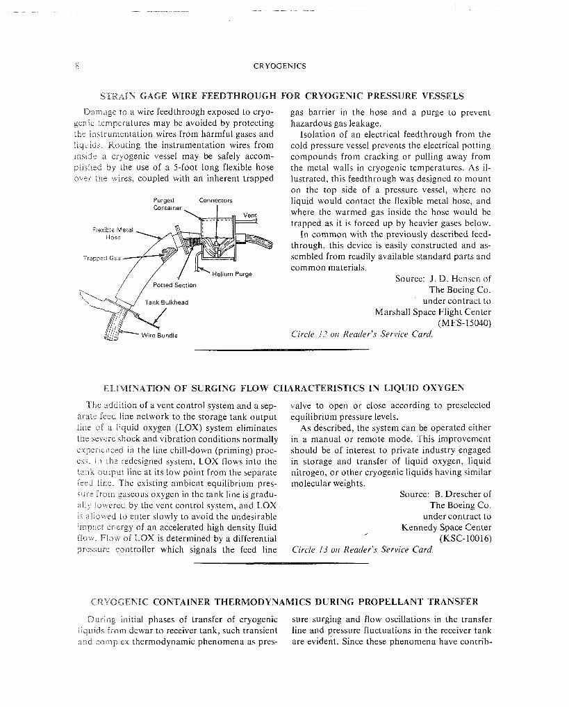
ELECTROMECHANICAL ROTARY ACTUATOR OPERATES OVER WIDE TEMPERATURE RANGE
Reliable operation,of an electromechanical actua- tor over a temperature range of +14O0 to -30OoF is made possible by avoiding the use of petroleum- based greases unsuitable for cryogenic applica- tions. Dry lubricants are used for the gears while
Actuator Frame Section Compression
Reduction Gear Fraye Screw
DETAIL B
Outer Belleville
ctuator Frame
DETAIL B
spacer
Washer
-.% Recess
the bearings are unlubricated to prevent nonfunc- tioning at cryogenic temperatures.
The actuator incorporates a spring stop designed to limit internal deceleration loads to a magnitude equal to stall torque. To achieve accurate position- ing of the stroke limit, the actuator unit comprises a reduction gear train, motor drive pinion, output shaft, and potentiometer as illustrated. Overtravel of the output shaft is below 1.50, which is less than a full revolution of the motor.
The entire assembly is environmentally sealed by welding a cover to the frame. To avoid pene- tration of fluids along the output shaft, inner and outer seals are provided. The brea between the seals is ported to the atmosphere to drain any fluid passing the outer seal, and avoid the possibility of such material entering the inner sealed area.
Source: S. F. Sullivan of North American Rockweli Gorp.
under contract to Marshall Space Flight Center
(MFS-18402) Circle I I on Reader's Service Card.
Potentiometer DETAIL A
A LIQUID HYDROGEN INLET DISTRIBUTOR
Damaging stresses arising from the transfer of supercold liquid gases from a feeder line into a manifold system may be reduced by an internal spray distributor within the inlet header to provide an equalized chill-down of the inlet header and to minimize thermal distortion of both headex and flanged joints.
Previously, temperature distribution to the va- porizer coils was uneven, causing the inlet header to bow excessively and to impose abnormal stres- ses on the flanged joints. The use of an inlet header diversion plate to improve fill and distribute the flow to the vaporizer coils was unsatisfactory. Con- sequently, the diversion plate and the flanges were removed from the inlet header and the internal spray distributor installed. By connecting the dis-
tributor to the liquid gas source, equalized cooling around the circumference of the inlet header was achieved. The distributor provides for the vapori- zation of the liquid being sprayed on the iann?edi- ate areas of the inlet header resulting in eqiiaEEzed chill-down of the vaporizer system.
This device may be used in any appliclitio~i where supercold liquid gases are transferred from a feeder line into a system which is at ambient temperature.
Source: R. H. Roberts and \N. J . Btiri-rs of The Boelng Co.
under contract to Kennedy Space Center
(KSC-10388) No further documentatio~l is available.
8 CRYOGENICS
S T R A I N G A G E W I R E F E E D T H R O U G H F O R C R Y O G E N I C P R E S S U R E V E S S E L S
Daindge to a wire feedthrough exposed to cryo- genic temperatures may be avoided by protecting the snistsurnentation wires from harmful gases and l i q ~ ~ ~ d s Routing the instrumentation wires from ~nside a cryogenic vessel may be safely accom- pl~shsd by the use of a 5-foot long flexible hose over the wlres, coupled with an inherent trapped
Purged Connectors Container I
Flexible Metal Hose
Trapped Gas
,/ / Potted Section r\
gas barrier in the hose and a purge to prevent hazardous gas leakage.
Isolation of an electrical feedthrough from the cold pressure vessel prevents the electrical potting compounds from cracking or pulling away from the metal walls in cryogenic temperatures. As il- lustrated, this feedthrough was designed to mount on the top side of a pressure vessel, where no liquid would contact the flexible metal hose, and where the warmed gas inside the hose would be trapped as it is forced up by heavier gases below.
In common with the previously described feed- through, this device is easily constructed and as- sembled from readily available standard parts and common materials.
Source: J. D. Hensen of The Boeing Co.
under contract to Marshall Space Flight Center
(MFS- 15040) Circle I? 011 Reader's Service Card.
E L I M I N A T I O N O F S U R G I N G F L O W C H A R A C T E R I S T I C S I N L I Q U I D O X Y G E N
The addition of a vent control system and a sep- asaie feed line network to the storage tank output line of a liquid oxygen (LOX) system eliminates the severe shock and vibration conditions normally experienced in the line chill-down (priming) proc- ci. In the redesigned system, LOX flows into the tank ~ L I L P U I . line at its low point from the separate feed Pine. The existing ambient equilibrium pres- sure from gaseous oxygen in the tank line is gradu- ally lowered by the vent control system, and LOX i h ailowed to enter slowly to avoid the undesirable impact energy of an accelerated high density fluid flow. Flow of LOX is determined by a differential pressure controller which signals the feed line
valve to open or close according to preselected equilibrium pressure levels.
As described, the system can be operated either in a manual or remote mode. This improvement should be of interest to private industry engaged in storage and transfer of liquid oxygen, liquid nitrogen, or other cryogenic liquids having similar molecular weights.
Source: B. Drescher of The Boeing Co.
under contract to Kennedy Space Center
(KSC- 100 16) Circle 13 011 Reader's Service Card.
C R Y O G E N I C C O N T A I N E R T H E R M O D Y N A M I C S D U R I N G P R O P E L L A N T T R A N S F E R
During initial phases of transfer of cryogenic sure surging and flow oscillations in the transfer iiquiids from dewar to receiver tank, such transient line and pressure fluctuations in the receiver tank and complex thermodynamic phenomena as pres- are evident. Since these phenomena have contrib-
NEW AND IMPROVED DEVICES 9
uted to line rupture and receiver tank implosion, an exhaustive study has been performed using lab- oratory model analyses derived from empirical data fed to a digital computer.
Of particular interest in recefver tank perform- ance is the reaction of tank pressure in early trans- fer phase to the average size of liquid droplets in the liquid/vapor jet entering the tank. It has been determined that the basic cause of tank implosion is the evaporation rate of droplets entering the tank in the early transfer phase. If the droplets are small, evaporation is rapid, and energy is removed
from the vapor in the tank, causing a rap161 drop in tank pressure.
To reduce the rate of pressure drop. a baffle r s placed within the tank facing the inlet. The incorn- ing liquid is then forced along the tank wal: to re- duce ullage-liquid heat transfer.
Source: R. M. Vernon and J. 9. Brogan of Lockheed Missiles and Space Co.
under contract to Marshall Space Flight Center
(MFS-14380) Circle 14 on Reader's Service Card
LIQUID HYDROGEN STORAGE VESSEL WARM-UP
A systematic procedure for warming low pres- approximately 12 times before the pressure shnft sure cylindrical vessels to ambient temperatures, has decreased to about 60% of its anginal volume in order to repair them, has been devised to avoid and the vessel is in a liquid air temperature range damages caused by uncontrolled warming. If cryo- When the pressure decay in the annulus h a s de- pumped air is present in "Perlite-filled, vacuum- creased 33% of the original amount alter about 20 jacketed liquid hydrogen vessels," the inner tank cycles, the vessel should be above the bo~Blng must be emptied of the liquid hydrogen to prevent point of air and safe for faster warm-up over-pressurization. This procedure provides a measure of safety dur-
To initiate the procedure, it is necessary to in- ing the repair and servicing of liquid hydrogen stall 1000-micron range vacuum gages and com- vessels by commercial users. pound gages at the top and bottom of the vessel Source: W. M Bowers and and to connect a high capacity vacuum pump (300 W B. Ingleof to 400 cfm) to the annulus vacuum system. The North American Rockwell Corp inner vessel is pressurized through the top inlet under contract to with hydrogen gas at 30 to 45 psig. Pressurization Marshall Space Flagl~i. Center is then retained for 10 minutes to record the pres- (MFS-18182) sure shift and the vacuum readings of the annulus. Circle 15 oil Reader's Service Card This pressurization and release cycle is repeated
Section 3. Applications
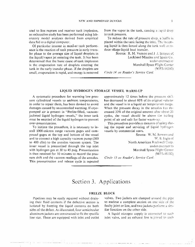
FREEZE BLOCK
Pipelines may be easily repaired without drain- valves. Two jackets are clamped around the pipe ing their fluid contents i f the defective section is to enclose a complete section on one side of the isolated by freezing the liquid contents on both faulty joint or line, and two jackets perform a sim- sides of the defect. As illustrated, four semicircular ilar function on the other side. aluminum jackets are constructed to fit the specific A liquid nitrogen supply is connected to eacn line size. These are equipped with inlet and outlet inlet valve, and an exhaust line is joined to each
10 CRYOGENICS
Section or Component ' to be Removed
Split Freeze Block
\ Clamp H
Freeze Blocks
Inlet Tubing Manifolds
outlet valve. Liquid nitrogen ( L N - I \ t h a crrcu- lated through the jackets until tl?e ilquld i n the pipe is frozen. At that point, the repair work accomplished. Upon completion of :epairi, the nitrogen source and the jackets are removed \o that the fluid flow can resume. Allhough tllr, con- cept is not novel, the application of cryo, "en~c fluid is inexpensive and easily performed
Source: J. T. Ernrnlck of North American Rockwell Coep
under contract to Manned Spacecraft Center
(MSC-11036) No further documer~tatio~~ is available
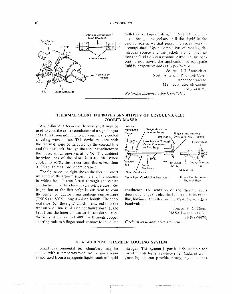
THERMAL SHORT IMPROVES SENSITIVITY OF CRYOGENICALLY COOLED MASER
An in-line quarter-wave thermal short may be coaxto
used to cool the center conductor of a signal input Mounts to
coaxial transmission line to a cryogenically cooled traveling wave maser. This device reduces both the thermal noise contributed by the coaxial line and the heat leak through the center conductor to the maser which operates a t 4.4"K. The ambient insertion loss of the short is 0.011 db. When cooled to 8O0K, the device contributes less than O.l°K to the maser noise temperature.
Cc pper Rod The figure on the right shows the thermal short outer Conductor
installed in the transmission line and the manner in which heat is transferred through the center conductor into the closed cycle refrigerator. Re- frigeration a t the first stage is sufficient to cool the center conductor from ambient temperature (290°K) to 80°K along a 4-inch length. The ther- mal short (on the right) which is inserted into the transmission line is of such configuration that the heat from the inner conductor is transferred con- ductively at the rate of 400 mw through copper shorting rods to a finger stock contact to the outer
Slgnal Input Coax~al Llne Assembly Ir -Lrne Ouarrer-Wave Thermal Shon
conductor. The addition of the i h e r i ~ ~ a i short does not change the electrical characteristics of the line, having slight effect on the VS'WR over a 25% bandwidth.
Source: R . C. Ciauss NASA ii%sadena Office
(NPO-09975) Circ le 16 otl reader,.^ Service C a d
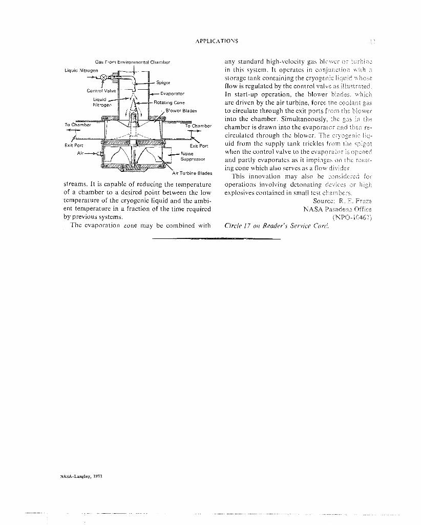
DUAL-PURPOSE CHAMBER COOLING SYSTEM
Small environmental test chambers may be nitrogen. This system is particularly suntable for cooled with a temperature-controlled gas stream use a t remote test sites where small tanks of cryo- evaporated from a cryogenic liquid, such as liquid genic liquids can provide steady, regulated gas
APPLICATIONS 1 I
Gas From Environmental Chamber
Exi
Suppressor
ir Turbine Blades
streams. It is capable of reducing the temperature of a chamber to a desired point between the low temperature of the cryogenic liquid and the ambi- ent temperature in a fraction of the time required by previous systems.
The evaporation zone may be combined with
any standard high-velocity gas blowel- o r iui-bine in this system. It operates in c o n j u ~ ~ c i i o t ~ wi!h a storage tank containing the cryoger-ic liquid wi~ose flow is regulated by the control valve as itlusirated. In start-up operation, the blower blades, which are driven by the air turbine, force the coolant gas to circulate through the exit ports from the blower into the chamber. Simultaneously, the gas i i ~ the chamber is drawn into the evaporator and the . re- circulated through the blower. Tht: cr-yogenic l i c ~ - uid from the supply tank trickles from the spigot when the control valve to the evaporator is opened and partly evaporates as it impingcs on the rotat- ing cone which also serves as a flow divider.
This innovation may also be zonsidcrcd for operations involving detonating devices o r high explosives contained in small test chan~l-iers.
Source: R. E. &'raze NASA Pasadena Office
(NPO-10467) Circle 17 or7 Reader's Service Card.
NASA SP-5932 (01) CRYOGENICS
READER SERVICE CARD
a Please send me information on other Technology Utilization publications and services. Please send me information on how I can receive NASA Tech Briefs and compilations.
Circle key number for additronal ~nforrnatron
-- I M Y MA1 Ll N G ADDRESS I S (~ lease tvoe or orint information i n soaces orovided below)
NAME TITLE
COMPANY (if any)
NASA SP-5932 (01) CRYOGENICS
READER SERVICE CARD
Please send me information on other Technology Utilization publications and services. a Please send me information on how I can receive NASA Tech Briefs and compilations.
Circle key number for additional inkoirna:ion.
I----
NASA SP-5932 (01) CRYOGENICS
READER SERVICE CARD
Please send me information on other Technology Utilization publications and services. Please send me information on how I can receive NASA Tech Briefs and compilations.
C~rcle key number for add~tronal ~nfermal ron
1 2 3 4 5 6 7 8 9 1 0 1 1
13 14 15 16 17
I CITY I STATE I
WASH~NGTON, D. C. 20546
OFFICIAL BUSINESS PENALTY FOR PRIVATE USE $300
POSTAGE AND FEES PAID NATIONAL AERONAUTICS AND
SPACE ADMINISTRATION
NASA Scientific and Technical lnformation Facility
Code TI Post Office Box 33 College Park, Maryland 2 0 7 4 0
NATIONAL AERONAWT~CS AND :SPACE ADMINISTRAT ION
WASHINGTON, D. 6. 20546
OFFICIAL BUSINESS PENALTY FOR PRIVATE USE $300
POSTAGE AND FEES PAID NATIONAL AERONAUTICS AND
SPACE ADMINISTRATION
NASA Scientific and Technical information Facility
Code TI Post Office Box 33 College Park, Maryland 2 0 7 4 0
N A T ~ O N A L ~ERCPNAUTICS AND SPACE ADMINISTRATION
WASHINGTON, D. C . 20546
OFTICIAL BUSINESS WENALTY FOR PRIVATE USE $300
POSTAGE AND FEES PAID NATIONAL AERONAUTICS AND
SPACE ADMINISTRAnON
NASA Scientific and Technical lnformation Facility
Code TI Post Office Box 33 College Park, Maryland 2 0 7 4 0
NATIONAL AERONAUTICS AND SPACE ADMINISTRATION WASHINGTON, D. C. 20546
OFFICIAL BUSINESS PENALTY FOR PRIVATE USE $300
- STAGE AND FEES PAID NATIONAL AEROMAWFICS AND
SPACE ADMINISTRATION
If Undeliverable (Section 158 Posral Manval ) Do Nor Return
- - - 2 1 . . - - -
-- . -- - ' T h e aerorwrutica,l and space activities if t h u n i t e d s h e s shall be
conducted so as t o contribpte . . . t o the expansion of ht{)~zart klzozul- edge of phe?zontena in the irtt~zosphere nlzd space. T h e Administmtion shall provide for the widest pmcticable alzd appropriate dissenrinatio?~ of inforu~ntio?z coficerning its dctivities nnd the restilts thereof."
-NATIONAL AERONAUTICS AND SPACE ACT OF 1958
NASA TECHNOLOGY L . A-IZATION PUBLICATIONS
These describe science or technology derived from NASA's activities that may be of particular interest in commercial and other non-aerospace applications. P~~blications include:
TECH BRIEFS: Single-page descriptions of Technology Utilization publications are part individual innovations, devi,ces, methods, or of NASA's formal series of scientific and concepts.
technical publications. Others include Tech-
SURVEYS' sL1rveys nical Reports, Technical Notes, Technical of NASA contributions to entire areas of technology. Memorandums, Contractor Reports, Technical
OTHER ,,.. PUBLICATIONS: These inclr,de Translations, and Special Publications.
handbooks, reports, conference proceedings. special studies, and selected bibliographies. Details on their availability may ~e
obtained from:
Details on the availability of these publications may be obtaFned from:
National Aeronautics apd
Space Adminissration
Code K T
Washington, D.c..' 20%46'
National Aeronautics and
Space Administration
Code KS
Washington. D.C. 20546
NATIONAL AERONAUTICS AND SPACE ADMINISTRATION Washington, D.C. 20546