Embed Size (px)
Citation preview
Available online at www.sciencedirect.com
www.elsevier.com/locate/actamat
Acta Materialia 57 (2009) 1777–1784
Crystal plasticity simulations using discrete Fourier transforms
Marko Knezevic *, Hamad F. Al-Harbi, Surya R. Kalidindi
Department of Materials Science and Engineering, Drexel University, Philadelphia, PA 19104, USA
Received 10 October 2008; received in revised form 14 December 2008; accepted 15 December 2008Available online 29 January 2009
Abstract
In this paper, we explore efficient representation of all of the functions central to crystal plasticity simulations in their complete respec-tive domains using discrete Fourier transforms (DFTs). This new DFT approach allows for compact representation and fast retrieval ofcrystal plasticity solutions for a crystal of any orientation subjected to any deformation mode. The approach has been successfullyapplied to a rigid–viscoplastic Taylor-type model for face-centered cubic polycrystals. It is observed that the novel approach describedherein is able to speed up the conventional crystal plasticity computations by two orders of magnitude. Details of this approach aredescribed and validated in this paper through a few example case studies.� 2008 Acta Materialia Inc. Published by Elsevier Ltd. All rights reserved.
Keywords: Microstructures; Taylor-type crystal plasticity models; Plastic deformation; Spectral methods
1. Introduction
Crystal plasticity theories are used extensively [1–9] inunderstanding and predicting the evolution of the underly-ing microstructure (mainly texture related aspects) and theconcomitant anisotropic stress–strain response in polycrys-talline metals subjected to finite plastic strains. Such phys-ics-based constitutive theories are highly desirable forconducting more accurate simulations of various metalmanufacturing/fabrication processes, since they providebetter understanding and predictions of the materialbehavior [10–12]. The main deterrent in the more wide-spread use of these theories (in place of the highly simpli-fied phenomenological isotropic plasticity theoriestypically used) is the fact that the implementation of thecrystal plasticity theories in a finite element modelingframework demands substantial computational resourcesand highly specialized expertise.
A number of strategies are being explored currently tospeed up the crystal plasticity calculations. The most prom-ising of these strategies appear to be those that seek effi-cient spectral representations combined with a database
1359-6454/$36.00 � 2008 Acta Materialia Inc. Published by Elsevier Ltd. All
doi:10.1016/j.actamat.2008.12.017
* Corresponding author. Tel.: +1 215 895 2335; fax: +1 215 895 6760.E-mail address: [email protected] (M. Knezevic).
approach that stores the main characteristics of the crystalplasticity solutions. Li et al. [13] and Kalidindi and Duvv-uru [14] have demonstrated the viability of the Bunge–Esl-ing approach [15,16] using generalized spherical harmonics(GSH) for texture evolution. In this approach, the impor-tant details of texture evolution are captured in a databaseof streamlines for a selected deformation process. A pro-cess plane concept, based on proper orthogonal decompo-sition in Rodrigues–Frank space [17], has been presentedby Sundararaghavan and Zabaras [18], again for selecteddeformation modes. Both the streamline approach andthe process plane approach have not yet been successfullygeneralized for arbitrary deformation modes. Moreover,these models are based on conservation principles in theorientation space that do not presently resolve the differ-ences in the strain hardening responses of differently ori-ented crystals.
In recent work [19,20], we have identified that the crystalplasticity solutions for face-centered cubic (fcc) polycrys-tals experiencing rigid–viscoplastic deformations can beorganized efficiently as a set of functions that describe thedependence of the stresses, the lattice rotations and thetotal slip rates in individual crystalline regions on their lat-tice orientation and the imposed velocity gradient tensor(quantifying the deformation mode) on those regions.
rights reserved.

1778 M. Knezevic et al. / Acta Materialia 57 (2009) 1777–1784
The domain of these functions was defined to be the prod-uct space comprising all possible crystal orientations andall possible isochoric deformation modes. Even thoughthe viability of this framework using GSH representationsof texture was demonstrated [19], it did not produce theexpected dramatic improvements in the computationalspeed. Recognizing that the relatively high computationalcost of evaluating the GSH was the main limitation in thisapproach, we recently explored the use of discrete Fouriertransforms (DFTs), in place of the GSH, in the develop-ment of appropriate spectral databases [20]. In this mostrecent work, we stored the values of the various desiredfunctions on a discrete grid in their respective domainsand used local DFT-based interpolations for evaluatingthe values of the function at any other desired location.In doing so, we recognized that the major advantage ofusing DFTs in place of GSH coefficients is that the DFTscan be computed extremely fast using well-established,highly efficient algorithms [21–25]. Indeed, the databaseof discretized function values together with the localDFT-based interpolation method was found to speed upthe crystal plasticity calculations by an order of magnitudewhen compared to the traditional computations in fccmetals [20].
Building on these prior efforts, we have now exploredthe representation of all of the functions capturing crystalplasticity solutions in their complete respective domainsusing DFTs. The most remarkable discovery in this newdirection was the recognition that only a limited numberof the dominant DFTs were needed to recover the func-tions of interest across their entire respective domains. Thisapproach is akin to a global spectral interpolation asopposed to the local spectral interpolation used in our ear-lier approach [20]. Also, in our previous approach, the glo-bal spectral database constituted the set of discretizedfunction values, which can be thought of as a primitiveFourier representation. By using DFTs directly to buildour spectral database, we are transforming from a primi-tive Fourier representation to the classical Fourier repre-sentation (with discrete frequencies). This new approachwas found to be able to speed up the crystal plasticity com-putations by another order of magnitude compared to ourmost recent approach (i.e. about two orders of magnitudefaster than the traditional approaches used in crystal plas-ticity computations). The details of this new approach arepresented and discussed in this paper. A particularly attrac-tive feature of this new approach is that it provides the userwith tremendous flexibility in making trade-offs betweenaccuracy and computational speed. In other words, thenew spectral database described in this paper will allowthe user to perform a large number of very quick simula-tions at a lower than desired accuracy, identify the specificones that appear to produce promising results and redothem much more accurately (at a higher computationalcost).
In the present study, we have confined our attention torigid–plastic Taylor-type (full constraints) model calcula-
tions for fcc polycrystals with equal hardening of all slip sys-tems. Application of this approach to more sophisticatedconstitutive models (such as elastic–viscoplastic models withlatent hardening) and higher-order homogenization theories(such as LAMEL [8] or self-consistent [26] models) will beexplored in future work. The new approach presented in thiswork was validated by comparing the solutions obtained bythe conventional computational approaches against thoseobtained from the spectral approach described here for afew selected examples of deformation processes.
2. Crystal plasticity framework
The rigid–viscoplastic crystal plasticity model [1] used inthis work can be described by the following set ofequations:
D ¼X
a
_caPa; Pa ¼ 0:5ðma � na þ na �maÞ ð1Þ
_ca ¼ _cosa
sa
��������1=m
sgnðsaÞ; sa ¼ r0 � Pa ð2Þ
In Eqs. (1) and (2), D is the applied isochoric stretchingtensor, and ma and na are the unit vectors identifying theslip direction and the slip plane normal, respectively, forslip system a. For the fcc crystals studied in this paper,the family of twelve f111gh1�10i slip systems were consid-ered as potential slip systems. The deviatoric componentof the Cauchy stress tensor in the crystal, denoted by r0,can be evaluated by solving Eqs. (1) and (2). sa, _ca, andsa represent the resolved shear stress, the shearing rateand the slip resistance, respectively, of slip system a. Thereference value of the shearing rate, _co, is taken here as0.001 s�1 for quasi-static loading conditions. The strainrate sensitivity parameter, denoted by m, is taken to be0.01, which is in agreement with measurements on mostsingle phase fcc metals at low homologous temperatures.The lattice spin tensor W* (and the related lattice rotationtensor, R*) in the crystalline region is given by
W� ¼ _R�R�T ¼Wapp �Wp; Wp
¼X
a
0:5_caðma � na � na �maÞ ð3Þ
where Wapp is the applied spin tensor and Wp is the plasticspin tensor.
In this study, we have adopted a simplified saturationtype hardening law, which assumes that the slip resistancesof all slip systems at any given location in a crystallineregion exhibit the same slip resistance. They are, however,allowed to vary from one location to another depending onthe local crystal orientation and the deformation history.This simplified slip hardening law is expressed as
_sa ¼ ho 1� sa
ss
� �aXb
j _cbj ð4Þ
where ho, ss, and a denote the slip hardening parameters.The values of the slip hardening parameters were taken

M. Knezevic et al. / Acta Materialia 57 (2009) 1777–1784 1779
here to correspond to the values established previously bycalibrating the Taylor-type model to experimental mea-surements [4] in oxygen-free high conductivity (OFHC)copper. The values were ho ¼ 180 MPa;ss ¼ 148 MPa;a ¼2:25 and so ¼ 16 MPa, where so denotes the initial slipresistance.
3. Crystal plasticity using DFTs
The crystal plasticity computations typically demandsignificant computational resources because of the lowvalue of m (which makes the resulting system of algebraicequations numerically extremely stiff). Moreover, the samecomputations are likely to be repeated several times in sim-ulations performed by the conventional approach, becausethe results of computations in any one time step are imme-diately forgotten when the computations advance to thenext time step. In the spectral crystal plasticity approach[19,20], our goal is to establish efficient spectral representa-tions for the essential functions capturing the solutions tothe crystal plasticity theory described above. In otherwords, our interest here is in establishing the functionsr0ijðg;LÞ;W �
ijðg;LÞ andP
aj _cajðg;LÞ, where g is the crystallattice orientation and L is the applied velocity gradienttensor. In any given time step in the simulation of thedeformation process, these functions can then be used tocompute all of the needed microscale and macroscale fieldquantities that would be typically computed by the tradi-tional crystal plasticity approach.
In the simple Taylor-type models, the applied velocitygradient tensor at the microscale is assumed to be the sameas the one applied at the macroscale (on the polycrystal).The macroscopic stress for the polycrystal is then obtainedby volume averaging the stresses inside the polycrystal. Inusing the spectral databases described here with moresophisticated homogenization theories, it will be necessaryto first solve for the local (microscale) velocity gradient ten-sor to be applied and then use that as input to the functionsdescribed above.
Next, we describe a strategy for compacting the domainof the functions described earlier. Following the approachdescribed by Van Houtte [27], the applied traceless velocitygradient tensor (plastic deformations in metals are iso-choric), L, is additively decomposed into a spin compo-nent, Wapp, and a traceless stretching component, D,which can be expressed using a single angular variable inits principal frame. This decomposition can be mathemati-cally expressed as
L¼ _eDoþWapp Do¼X3
j¼1
Djepj � e
pj _e¼ jDj;
D1¼ffiffiffi2
3
rcos h�p
3
� �; D2¼
ffiffiffi2
3
rcos hþp
3
� �; D3¼�
ffiffiffi2
3
rcos hð Þ;
ð5Þ
where fepi ; i ¼ 1; 2; 3g denotes the principal frame of D, and
the range of angular variable h that defines all possible
diagonal matrices is [0,2p). Consequently, the functionswe seek can be expressed in terms of ðh; _e; fepg;WappÞ, in-stead of L. As an example, the function for the deviatoricstress in the crystal can be expressed as r0ijðg; h; _e;fepg;WappÞ. Recognizing that all crystal plasticity computa-tions can be performed in the {ep} reference frame and con-verted back to the sample reference frame when needed, wecan transform (g, {ep})) gp, where gp denotes the crystalorientation with respect to the {ep} reference frame. Fur-thermore, the roles of variables _e and Wapp in the functionsof interest here can be explicitly described. These simplifi-cations allow us to focus our efforts on building the spectraldatabases on two primary variables, gp and h. In otherwords, we will be seeking spectral representations ofr0(gp,h), W*(gp,h), and
Paj _cajðgp; hÞ. For the tensorial vari-
ables listed above (stresses and lattice rotations), thesefunctions will describe the components in the principalframe of the stretching tensor, which can then be trans-formed appropriately to the sample or crystal referenceframes, as needed. Spectral representations of these func-tions using DFTs can be expressed as
W�rq ¼ _e
1
NgN h
Xk
Xn
Bkne2pikrNg e
2pinqNh þWapp ð6Þ
r0rq ¼ sj_ejmsgnð_eÞ 1
N gN h
Xk
Ckne2pikrNg e
2pinqNh ð7Þ
Xa
j _caj !
rq
¼ j_ej 1
NgN h
Xk
Xn
Gkne2pikrNg e
2pinqNh ð8Þ
In Eqs. (6)–(8), r and q enumerate the grid points while Ng
and Nh represent the total number of grid points in the ori-entation space (domain of gp) and the h space (describingthe deformation mode), respectively. The sets of coeffi-cients Bkn, Ckn, and Gkn are referred to as the DFTs, andare completely independent of the values of the variablesgp and h at grid points r and q.
In order to compute these transforms, we first need tocompute the values of the functions of interest on a uni-form grid in the naturally periodic product space definedby the Bunge–Euler space and the deformation modespace. These values are computed using the crystal plastic-ity theory described earlier. In this work, this was accom-plished using a regular three-degree grid in each of theangular variables involved. The Bunge–Euler space ofinterest in computing DFTs for orientation-dependentperiodic functions in cubic crystals can be identified as(u1 e [0, 2p), U e [0,2p), u2 e [0, 2p)) [28]. The periodic spaceof interest in defining the deformation mode is identified ash e [0, 2p). It is further emphasized that the space describedabove has been chosen as it provides the natural periodicityfor all the functions of interest identified earlier. All thefunctions of interest have very efficient spectral representa-tion in this space, which will become apparent later. Itshould be noted that quite a few redundancies exist in thespace identified above. In other words, a selected combina-tion of a lattice orientation and a deformation mode have
1780 M. Knezevic et al. / Acta Materialia 57 (2009) 1777–1784
multiple (but equivalent) representations in this space.These equivalent representations have been exploited inthe computations of the function values.
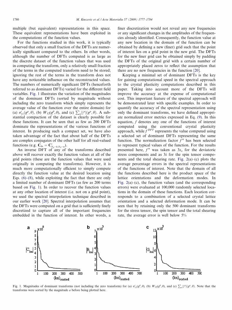
For the functions studied in this work, it is typicallyobserved that only a small fraction of the DFTs are numer-ically significant compared to the others. In other words,although the number of DFTs computed is as large asthe discrete dataset of the function values that was usedin computing the transform, only a relatively small fractionof the terms in the computed transform need to be stored;ignoring the rest of the terms in the transform does nothave any noticeable influence on the reconstructed values.The numbers of numerically significant DFTs (henceforthreferred to as dominant DFTs) varied for the different fieldvariables. Fig. 1 illustrates the variation of the magnitudesof the dominant DFTs (sorted by magnitude withoutincluding the zero transform which simply represents theaverage value of the function over the entire domain) for(a) r011ðgp; hÞ; (b) W12(gp,h), and (c)
Paj _cajðgp; hÞ. A sub-
stantial compaction of the dataset is clearly possible forthese functions. It can be seen that as few as 200 DFTsdominate the representations of the various functions ofinterest. In producing such a compact set, we have alsotaken advantage of the fact that about half of the DFTsare complex conjugates of the other half for all real-valuedfunctions (e.g. Ckn ¼ C�Ng�k;Nh�n).
An inverse DFT of any of the transforms describedabove will recover exactly the function values at all of thegrid points (these are the function values that were usedoriginally in computing the transforms). However, it ismuch more computationally efficient to simply computedirectly the function value at the desired location usingEqs. (6)–(8), while exploiting the fact that there are onlya limited number of dominant DFTs (as few as 200 termsbased on Fig. 1). In order to recover the function valuesat any other location of interest (i.e. not on a grid point),we used the spectral interpolation technique described inour earlier work [20]. Spectral interpolation assumes thatthe DFTs were computed on a grid that is sufficiently finelydiscretized to capture all of the important frequenciesembedded in the function of interest. In other words, a
Fig. 1. Magnitudes of dominant transforms (not including the zero transfortransforms were sorted by the magnitude a before being plotted here.
finer discretization would not reveal any new frequenciesor any significant changes in the amplitudes of the frequen-cies already identified. Consequently, the function value atany new location in the domain of the function can beobtained by defining a new (finer) grid such that the pointof interest lies on a grid point in the new grid. The DFTsfor the new finer grid can be obtained simply by paddingthe DFTs of the original grid with a certain number ofappropriately placed zeros to reflect the assumption thatthere are no new frequencies in the function [20].
Keeping a minimal set of dominant DFTs is the keyfor gaining computational speed in the spectral approachto the crystal plasticity computations described in thispaper. Taking into account more of the DFTs willimprove the accuracy at the expense of computationalcost. This important feature of the spectral approach willbe demonstrated later with specific examples. In order toquantify the accuracy of the spectral representation usingonly the dominant transforms, we have defined appropri-ate normalized error metrics expressed in Eq. (9). In thisequation, f denotes any one of the functions of interestcomputed using the conventional crystal plasticityapproach, while f DFT represents the value computed usinga selected set of dominant DFTs representing the samefunction. The normalization factor f n has been selectedto represent typical values of the function. For the resultspresented here, f n was taken as 3so for the deviatoricstress components and as 3_e for the spin tensor compo-nents and the total shearing rate. Fig. 2(a)–(c) plots theaverage percentage errors in the spectral representationsof the functions of interest. Note that the domain of allthe functions described here is the product space of thelattice orientations and the deformation modes. InFig. 2(a)–(c), the function values (and the correspondingerrors) were evaluated at 100,000 randomly selected loca-tions in the domain of these functions. Each location cor-responds to a combination of a selected crystal latticeorientation and a selected deformation mode. It can beseen that by retaining only the 500 dominant transformsfor the stress tensor, the spin tensor and the total shearingrate, the average error is well below 5%
m) for (a) r011(gp,h), (b) W12(gp,h), and (c)P
aj _cajðgp; hÞ. Note that the

Fig. 2. Average percentage error between the spectral predictions and direct computations for 100,000 randomly selected orientations subjected torandomly selected deformation modes as a function of the number of the dominant DFTs used in the spectral databases: (a) r011(gp,h), (b) W12(gp,h), and(c)P
aj _cajðgp; hÞ.
M. Knezevic et al. / Acta Materialia 57 (2009) 1777–1784 1781
e ¼ 1
N
XN
1
jf � f DFT jf n
� 100 ð9Þ
For visual comparison, we present in Fig. 3 contourplots in the orientation space for the stress function for aprescribed deformation mode, i.e. r011ðgpÞ
��h¼ho
. The plotscompare function values computed using the conventionalcrystal plasticity computations and using the spectral meth-ods described here with only the 500 dominant DFTs. It isseen that the DFT method described in this work repro-duces faithfully the conventional crystal plasticity modelpredictions. Several other similar checks were conductedon the various functions of interest in this work.
4. Case studies
4.1. Plane strain compression
In order to demonstrate the validity of the new DFT-based spectral approach described in this work, we simu-lated plane strain compression on polycrystalline OFHCcopper to a true strain of e = �1.0 along the compressionaxis. The polycrystal was assumed to possess a random ini-tial texture that was captured by a set of 1000 discrete crys-tal orientations. We computed the deformed textures andthe anisotropic stress–strain curves using the Taylor-typemodel, both by the traditional approach and the new
Fig. 3. Contour plots of r011ðgpÞjh¼hoin Bunge-Euler space. (a) Computed
using 500 dominant DFTs. (b) Computed using the conventional crystalplasticity approach.
DFT spectral approach based on the dominant transformsdescribed here. In the DFT method, we applied Eqs. (6)–(8)recursively 20 times, each time for a true strain step of�0.05. In each strain step, the grain orientations wereupdated and the new orientations were used as the startingorientations in the next strain step. The predicted texturesfrom the traditional approach are compared against thoseobtained from the DFT method using a minimal set ofdominant transforms (134 for stress, 255 for lattice spinand 182 for shearing rate) in Fig. 4(a), while the corre-sponding predictions of the stress–strain responses areshown in Fig. 4(b). Another calculation was performedusing more of the dominant DFTs (500 for stress andshearing rate and 3000 for lattice spin), and its comparisonwith predictions from the traditional approach is presentedin Fig. 5 (note the slight improvement in the accuracy ofthe spectral approach between Figs. 4 and 5). It is seen thatthe DFT method described here accurately reproduced allof the features of the Taylor-type model predictions.
This simulation took 108 s on a regular Pentium 4 desk-top PC using the conventional crystal plasticity algorithms(solving explicitly Eqs. (1) and (2)), but only 0.7 s using theminimal set of the dominant DFTs and 2.3 s using the lar-ger number of dominant DFTs. This represents a tremen-dous savings in computational time.
4.2. Simple shear
For the next case study, we simulated simple sheardeformation, where the principal orientations of theimposed stretching tensor do not coincide with the samplereference frame. The sample was assumed to have the samerandom initial texture as in the previous case study, andwas subjected to a strain of c = 1.0. The predictions fromthe new DFT spectral approach based on the 500 dominantDFTs for the stress components and the shearing rate, and3000 dominant DFTs for the lattice spin components, arecompared against the corresponding predictions from theconventional Taylor-type model calculations in Fig. 6. Itis seen once again that the DFT method described hereprovides excellent predictions at a significantly faster com-

Fig. 4. Comparison of the predictions from the spectral method described here, using a minimal set of 134 dominant DFTs for stress, 255 dominant DFTsfor lattice spin, and 182 dominant DFTs for shearing rate, against the corresponding predictions from the conventional Taylor-type model for plane straincompression of OFHC Copper: (a) pole figures, and (b) stress–strain curves.
Fig. 5. Comparison of the predictions from the spectral method, using 500 dominant DFTs for stress components and the shearing rate and 3000dominant DFTs for the lattice spin components, against the corresponding predictions from the conventional Taylor-type model for plane straincompression of OFHC Copper: (a) pole figures, and (b) stress–strain curves.
Fig. 6. Comparison of the predictions from the spectral method, using 500 dominant DFTs for stress components and the shearing rate and 3000dominant DFTs for the lattice spin components, against the corresponding predictions from the conventional Taylor-type model for simple shear ofOFHC Copper: (a) pole figures, and (b) stress–strain curves.
1782 M. Knezevic et al. / Acta Materialia 57 (2009) 1777–1784
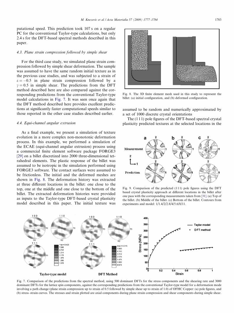
Fig. 8. The 3D finite element mesh used in this study to represent thebillet: (a) initial configuration, and (b) deformed configuration.
Fig. 9. Comparison of the predicted (111) pole figures using the DFTbased crystal plasticity approach at different locations in the billet afterone pass with the corresponding measurements taken from [31]. (a) Top ofthe billet. (b) Middle of the billet. (c) Bottom of the billet. Contours fromexperiments and model: 1/1.4/2/2.8/4/5.6/8/11.
M. Knezevic et al. / Acta Materialia 57 (2009) 1777–1784 1783
putational speed. This prediction took 107 s on a regularPC for the conventional Taylor-type calculations, but only2.4 s for the DFT-based spectral methods described in thispaper.
4.3. Plane strain compression followed by simple shear
For the third case study, we simulated plane strain com-pression followed by simple shear deformation. The samplewas assumed to have the same random initial texture as inthe previous case studies, and was subjected to a strain ofe = �0.5 in plane strain compression followed by ac = 0.5 in simple shear. The predictions from the DFTmethod described here are also compared against the cor-responding predictions from the conventional Taylor-typemodel calculations in Fig. 7. It was seen once again thatthe DFT method described here provides excellent predic-tions at significantly faster computational speeds similar tothose reported in the other case studies described earlier.
4.4. Equi-channel angular extrusion
As a final example, we present a simulation of textureevolution in a more complex non-monotonic deformationprocess. In this example, we performed a simulation ofthe ECAE (equi-channel angular extrusion) process usinga commercial finite element software package FORGE3[29] on a billet discretized into 2000 three-dimensional tet-rahedral elements. The plastic response of the billet wasassumed to be isotropic in the simulation performed usingFORGE3 software. The contact surfaces were assumed tobe frictionless. The initial and the deformed meshes areshown in Fig. 8. The deformation history was extractedat three different locations in the billet: one close to thetop, one at the middle and one close to the bottom of thebillet. The extracted deformation histories were providedas inputs to the Taylor-type DFT-based crystal plasticitymodel described in this paper. The initial texture was
Fig. 7. Comparison of the predictions from the spectral method, using 500 ddominant DFTs for the lattice spin components, against the corresponding preinvolving a path change (plane strain compression up to strain of 0.5 followed(b) stress–strain curves. The stresses and strain plotted are axial components du
assumed to be random and numerically approximated bya set of 1000 discrete crystal orientations
The (111) pole figures of the DFT-based spectral crystalplasticity predicted textures at the selected locations in the
ominant DFTs for the stress components and the shearing rate and 3000dictions from the conventional Taylor-type model for a deformation modeby simple shear up to strain of 1.0) of OFHC Copper: (a) pole figures, andring plane strain compression and shear components during simple shear.

1784 M. Knezevic et al. / Acta Materialia 57 (2009) 1777–1784
billet after one pass of ECAE were in reasonable agreementwith the experimentally measured textures, as shown inFig. 9. However, the agreement is much better for thetop and the middle locations on the billet compared tothe bottom location. In recent work [30,31], we have dem-onstrated that grain interactions and the associated anisot-ropy in the mechanical response of the material play animportant role in the texture gradients obtained in theECAE process. Since neither of these aspects of materialbehavior were incorporated in the present study, it is onlyreasonable to see some discrepancies between the predic-tions and the experimental measurements in Fig. 9. How-ever, it is gratifying to see that the present model is ableto capture the texture gradients obtained in the highly com-plex ECAE process to a reasonable extent.
5. Conclusions
It has been demonstrated that it is possible to speed upthe crystal plasticity calculations by two orders of magni-tude in fcc metals using a compact database of discreteFourier transforms (DFTs). It was seen that a limited setof dominant transforms adequately captured the depen-dence of the stresses, the lattice spins and the strain hard-ening in individual crystals as a function of their latticeorientation and the applied deformation mode. A compu-tationally efficient spectral interpolation scheme wasdevised and implemented to recover values of these func-tions for any selected combination of crystal orientationand deformation mode using only the dominant DFTs.The case studies revealed tremendous savings in the com-putational time, and provide a significant incentive forincorporation into the finite element simulations of bulkdeformation processing operations.
Acknowledgements
The authors gratefully acknowledge financial supportreceived for this work from NSF Grants CMS-0654179and CMS-0727931.
References
[1] Asaro RJ, Needleman A. Acta Metall Mater 1985;33:923.[2] Mathur KK, Dawson PR. Int J Plasticity 1989;5:67.[3] Bronkhorst CA, Kalidindi SR, Anand L. Phil Trans R Soc Lond Ser
A Math Phys Eng Sci 1992;341:443.[4] Kalidindi SR, Bronkhorst CA, Anand L. J Mech Phys Solids
1992;40:537.[5] Beaudoin AJ, Dawson PR, Mathur KK, Kocks UF. Int J Plasticity
1995;11:501.[6] Beaudoin AJ, Mathur KK, Dawson PR, Johnson GC. Int J Plasticity
1993;9:833.[7] Delannay L, Kalidindi SR, Van Houtte P. Mater Sci Eng A
2002;336:233.[8] Van Houtte P, Delannay L, Kalidindi SR. Int J Plasticity
2002;18:359.[9] Kalidindi SR, Bhattacharyya A, Doherty R. Proc R Soc Lond Math
Phys Eng Sci 2004;460:1935.[10] Raabe D, Zhao Z, Roters F. Steel Res 2001;72:421.[11] Raabe D, Wang Y, Roters F. Comput Mater Sci 2005;34:221.[12] Hosford WF, Caddell RM. Metal forming mechanics and metal-
lurgy. Englewood Cliffs, NJ: Prentice-Hall; 1993.[13] Li DS, Garmestani H, Schoenfeld S. Scripta Mater 2003;49:867.[14] Kalidindi SR, Duvvuru HK. Acta Mater 2005;53:3613.[15] Bunge H, Esling C. Scripta Metall 1984;18:191.[16] Clement A, Coulomb P. Scripta Metall 1979;13:899.[17] Frank FC. Metall Trans A 1987;19A:403.[18] Sundararaghavan V, Zabaras N. Acta Mater 2007;55:1573.[19] Kalidindi SR, Duvvuru HK, Knezevic M. Acta Mater 2006;54:1795.[20] Knezevic M, Kalidindi SR, Fullwood D. Int J Plasticity 2008;24:1264.[21] Press WH, Teukolsky SA, Vetterling WT, Flannery BP. Numerical
recipes in C++. Cambridge: Cambridge University Press; 2002.[22] Briggs WL, Henson VE. The DFT: an owner’s manual for the discrete
Fourier transform. Philadelphia, PA: Society for Industrial andApplied Mathematics; 1995.
[23] Brigham EO. The fast Fourier transform and applications. EnglewoodCliffs, NJ: Prentice Hall; 1988.
[24] Cooley JW, Tukey JW. Math Comput 1965;19:297.[25] Duhamel P, Vetterli M. Signal Process 1990;19:259.[26] Lebensohn RA, Tome CN. Acta Metall Mater 1993;41:2611.[27] Van Houtte P. Int J Plasticity 1994;10:719.[28] Bunge H-J. Texture analysis in materials science. Mathematical
methods. Gottingen: Cuvillier Verlag; 1993.[29] FORGE3. V6.3� 3D Forging Simulation Software. TRANSVALOR
S.A.[30] Li S, Kalidindi SR, Beyerlein IJ. Mater Sci Eng A 2005;410–411:207.[31] Kalidindi SR, Donohue BR, Li S. Int J Plasticity; in press.
doi:10.1016/j.ijplas.2008.06.008.