Embed Size (px)
Citation preview
CS 356: Computer Network Architectures
Lecture 15: IP address exhaustion
and End-to-end ProtocolsChapter 4.1, 5.1
Xiaowei Yang
Today• IP address exhaustion: problem and solutions
– IPv6 – Network Address Translation (NAT)
• End-to-end protocols– Turn the host-to-host delivery service into a process to
process communication channel– UDP and TCP
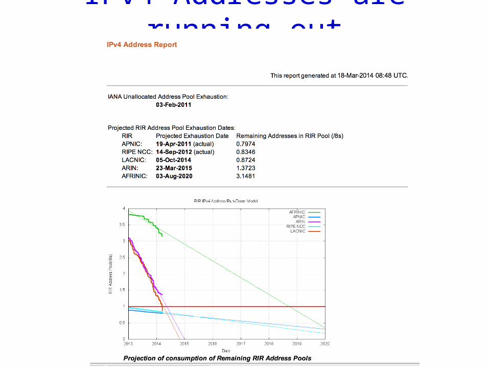
IPv4 Addresses are running out
Solutions
1. IPv6: longer addresses
2. Network Address Translation• Not all hosts have global unique addresses
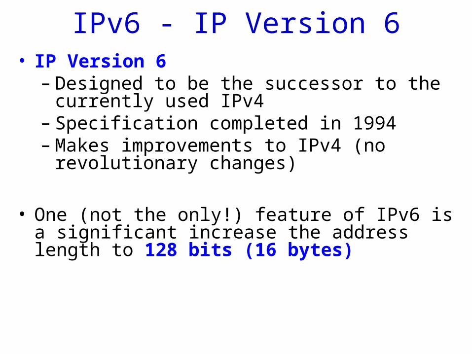
IPv6 - IP Version 6• IP Version 6
– Designed to be the successor to the currently used IPv4
– Specification completed in 1994– Makes improvements to IPv4 (no revolutionary
changes)
• One (not the only!) feature of IPv6 is a significant increase the address length to 128 bits (16 bytes)
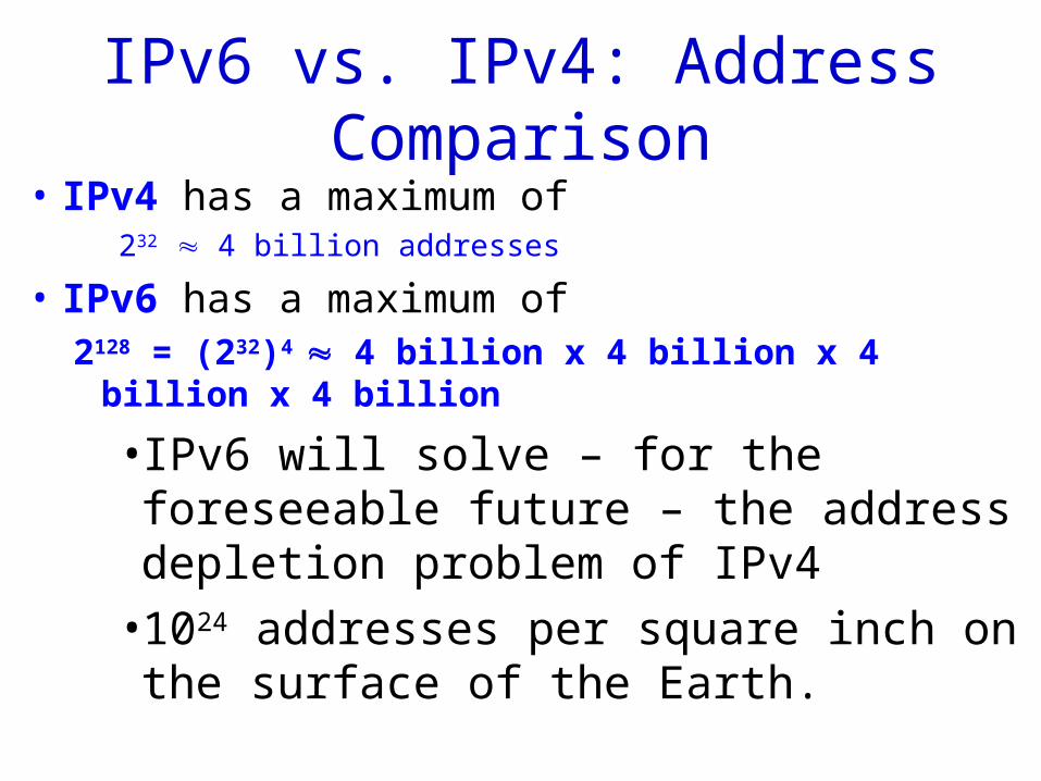
IPv6 vs. IPv4: Address Comparison
• IPv4 has a maximum of 232 4 billion addresses
• IPv6 has a maximum of 2128 = (232)4 4 billion x 4 billion x 4 billion x 4 billion
• IPv6 will solve – for the foreseeable future – the address depletion problem of IPv4
• 1024 addresses per square inch on the surface of the Earth.
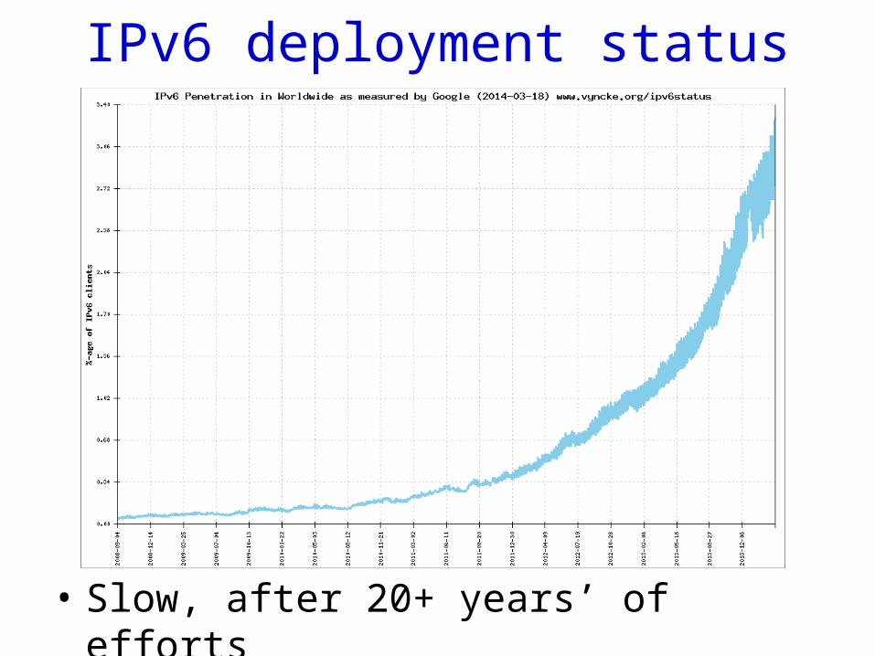
IPv6 deployment status
• Slow, after 20+ years’ of efforts
Network Address Translation
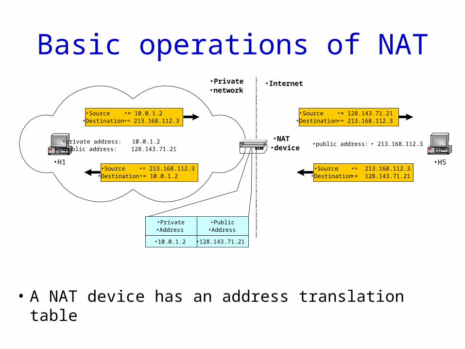
Basic operations of NAT
• A NAT device has an address translation table
•H1
•private address: 10.0.1.2•public address: 128.143.71.21
•H5
•Private•network
•Internet
•Source •= 10.0.1.2•Destination •= 213.168.112.3
•Source •= 128.143.71.21•Destination •= 213.168.112.3
•public address: • 213.168.112.3•NAT•device
•Source •= 213.168.112.3•Destination •= 128.143.71.21
•Source •= 213.168.112.3•Destination •= 10.0.1.2
•Private•Address
•Public•Address
•10.0.1.2 •128.143.71.21
Private Network• Private IP network is an IP network that is not directly
connected to the Internet
• IP addresses in a private network can be assigned arbitrarily – Not registered and not guaranteed to be globally unique– Public IP address are assigned via Internet registries
• Generally, private networks use addresses from the following experimental address ranges (non-routable addresses): – 10.0.0.0 – 10.255.255.255– 172.16.0.0 – 172.31.255.255– 192.168.0.0 – 192.168.255.255
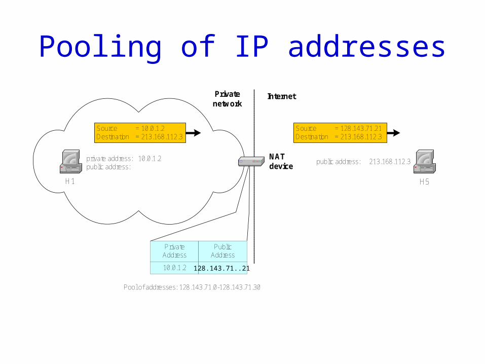
Pooling of IP addresses
H1
private address: 10.0.1.2public address:
H5
Privatenetwork
Internet
Source = 10.0.1.2Destination = 213.168.112.3
Source = 128.143.71.21Destination = 213.168.112.3
public address: 213.168.112.3NATdevice
PrivateAddress
PublicAddress
10.0.1.2
Pool of addresses: 128.143.71.0-128.143.71.30
128.143.71..21
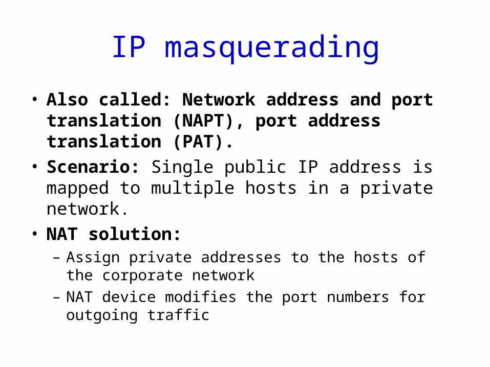
IP masquerading
• Also called: Network address and port translation (NAPT), port address translation (PAT).
• Scenario: Single public IP address is mapped to multiple hosts in a private network.
• NAT solution:– Assign private addresses to the hosts of the corporate
network
– NAT device modifies the port numbers for outgoing traffic
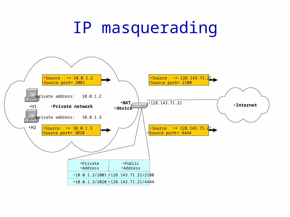
IP masquerading
•H1
•private address: 10.0.1.2
•Private network
•Source •= 10.0.1.2•Source port •= 2001
•Source •= 128.143.71.21•Source port •= 2100
•NAT•device
•Private•Address
•Public•Address
•10.0.1.2/2001 •128.143.71.21/2100
•10.0.1.3/3020 •128.143.71.21/4444
•H2
•private address: 10.0.1.3
•Source •= 10.0.1.3•Source port •= 3020
•Internet
•Source •= 128.143.71.21•Source port •= 4444
•128.143.71.21
Remarks on NAT
• Many complications, “a dirty hack”– A host’s IP address is no longer unique
• Can’t use an IP address in the payload
– Heavyweight• Need recompute TCP checksum that includes payload
• Widely used– In practice, few cares about architecture purity– Users and application developers can adapt– Performance issues are not critical
Transport protocols
Before: How to deliver packet from one host to another
• Direct link– Encoding, framing, error detection, reliability– Multi-access control
• Multi-link network switching and forwarding– Datagrams, virtual circuit– Bridges, spanning tree algorithm
• Interconnecting multiple networks– IP addressing, forwarding, routing
• ARP, distance vector, link state, path vector– Multicast and anycast– NAT, DHCP, VPN, tunnels etc.
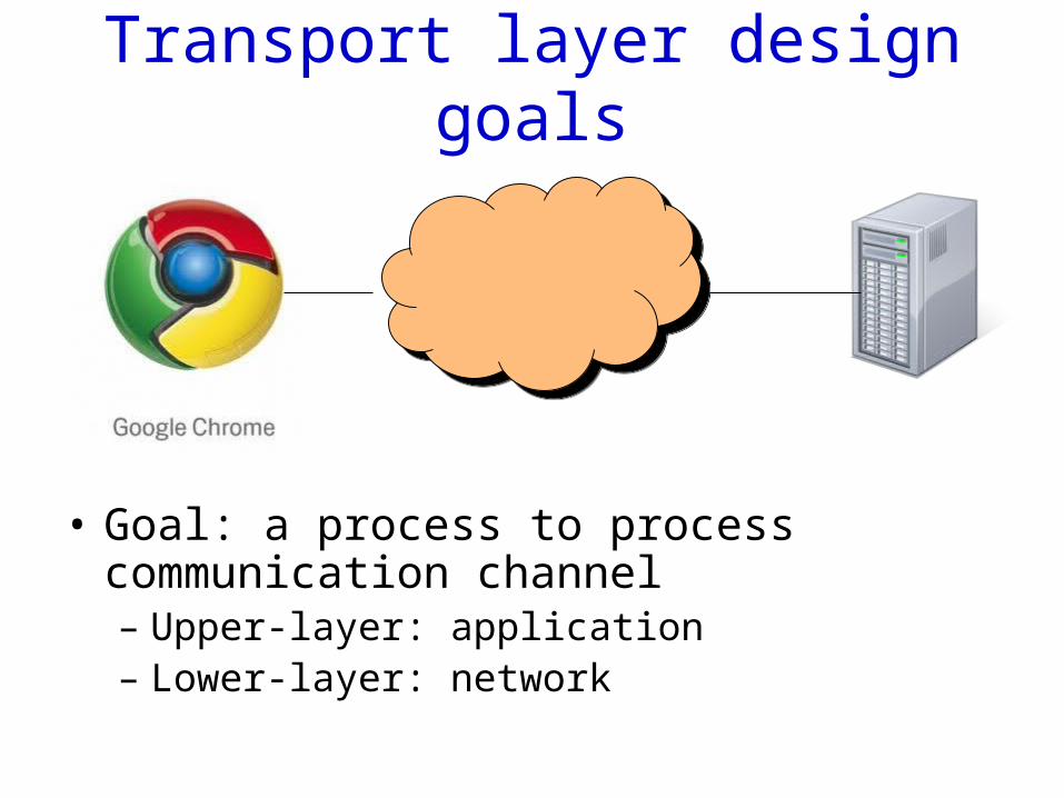
Transport layer design goals
• Goal: a process to process communication channel– Upper-layer: application– Lower-layer: network
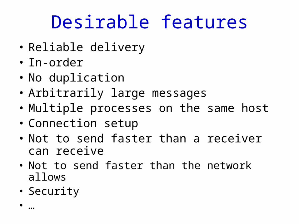
Desirable features• Reliable delivery• In-order• No duplication• Arbitrarily large messages• Multiple processes on the same host• Connection setup• Not to send faster than a receiver can receive• Not to send faster than the network allows• Security• …
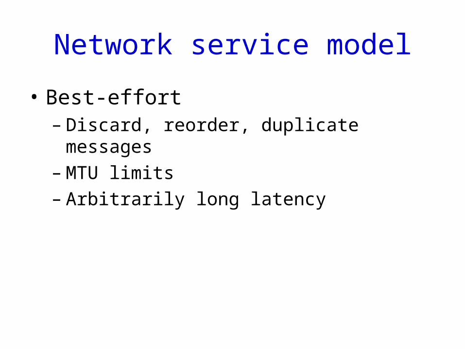
Network service model
• Best-effort– Discard, reorder, duplicate messages– MTU limits– Arbitrarily long latency
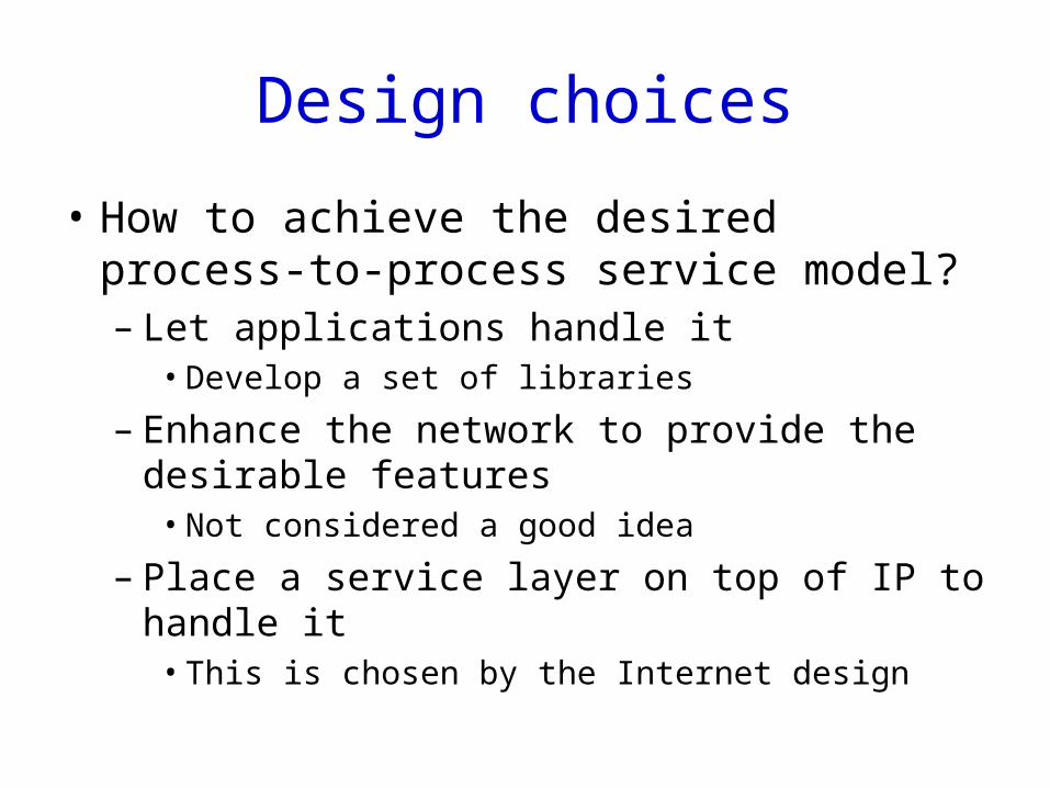
Design choices
• How to achieve the desired process-to-process service model?– Let applications handle it
• Develop a set of libraries
– Enhance the network to provide the desirable features
• Not considered a good idea
– Place a service layer on top of IP to handle it• This is chosen by the Internet design
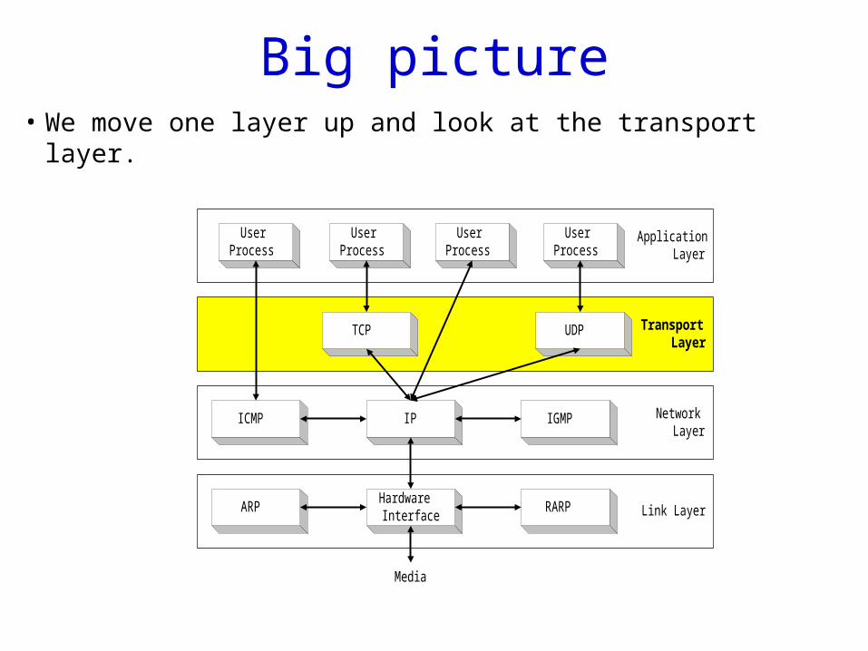
Big picture• We move one layer up and look at the transport layer.
ApplicationLayer
NetworkLayer
Link Layer
IP
ARPHardwareInterface
RARP
Media
ICMP IGMP
TransportLayer
TCP UDP
UserProcess
UserProcess
UserProcess
UserProcess
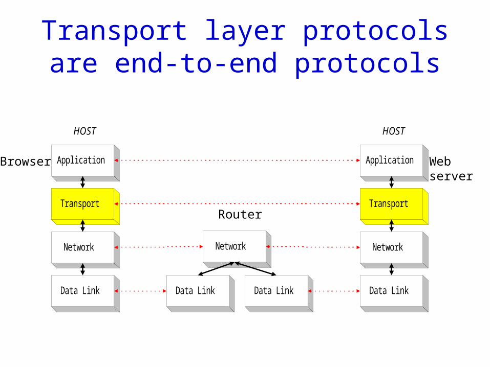
Transport layer protocols are end-to-end protocols
Application
Transport
Network
HOST
Data Link Data Link Data Link
Network
Application
Transport
Network
HOST
Data Link
Web server
Browser
Router
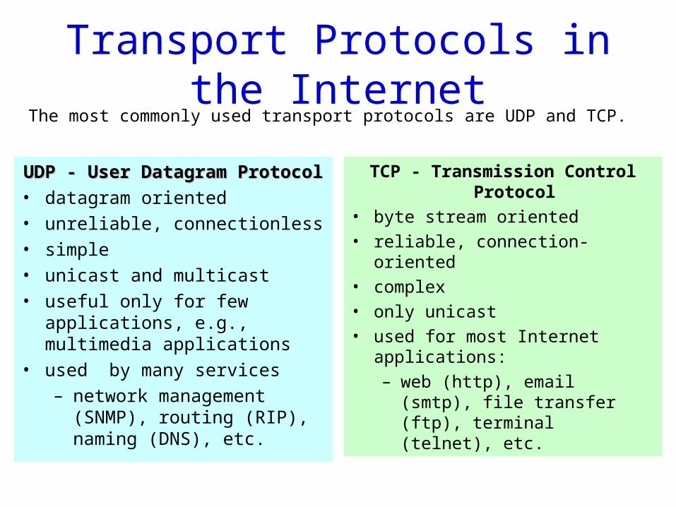
Transport Protocols in the Internet
UDP - User Datagram ProtocolUDP - User Datagram Protocol
• datagram oriented
• unreliable, connectionless
• simple
• unicast and multicast
• useful only for few applications, e.g., multimedia applications
• used by many services
– network management (SNMP), routing (RIP), naming (DNS), etc.
TCP - Transmission Control Protocol
• byte stream oriented
• reliable, connection-oriented
• complex
• only unicast
• used for most Internet applications:
– web (http), email (smtp), file transfer (ftp), terminal (telnet), etc.
The most commonly used transport protocols are UDP and TCP.
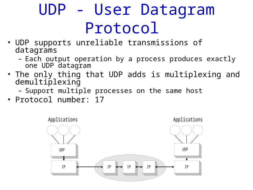
UDP - User Datagram Protocol • UDP supports unreliable transmissions of datagrams
– Each output operation by a process produces exactly one UDP datagram
• The only thing that UDP adds is multiplexing and demultiplexing– Support multiple processes on the same host
• Protocol number: 17
UDP
IP IPIP IP IP
UDP
Applications Applications
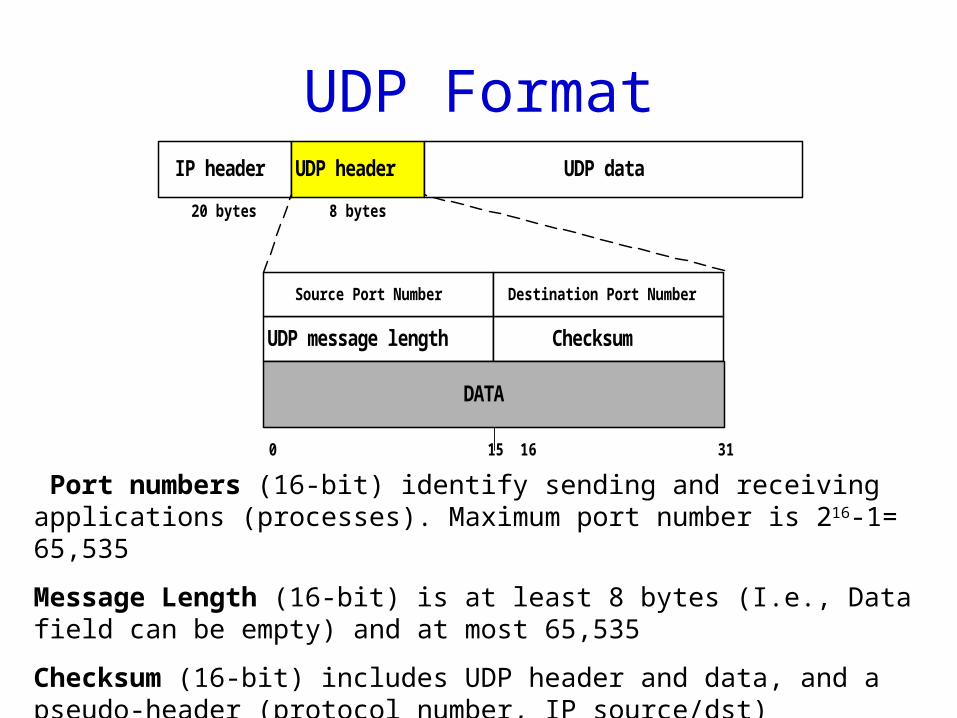
UDP FormatIP header UDP header UDP data
UDP message length Checksum
DATA
20 bytes 8 bytes
0 15 16 31
Source Port Number Destination Port Number
Port numbers (16-bit) identify sending and receiving applications (processes). Maximum port number is 216-1= 65,535
Message Length (16-bit) is at least 8 bytes (I.e., Data field can be empty) and at most 65,535
Checksum (16-bit) includes UDP header and data, and a pseudo-header (protocol number, IP source/dst) (optional IPv4, mandatory IPv6)
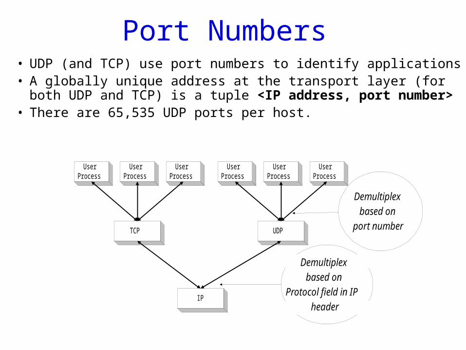
Port Numbers • UDP (and TCP) use port numbers to identify applications• A globally unique address at the transport layer (for both
UDP and TCP) is a tuple <IP address, port number>• There are 65,535 UDP ports per host.
IP
TCP UDP
UserProcess
Demultiplex
based on
Protocol field in IP
header
UserProcess
UserProcess
UserProcess
UserProcess
UserProcess
Demultiplex
based on
port number
How to find out application ports
• Servers use well-known ports– DNS: 53– /etc/services
• A server learns a client’s port from its packets
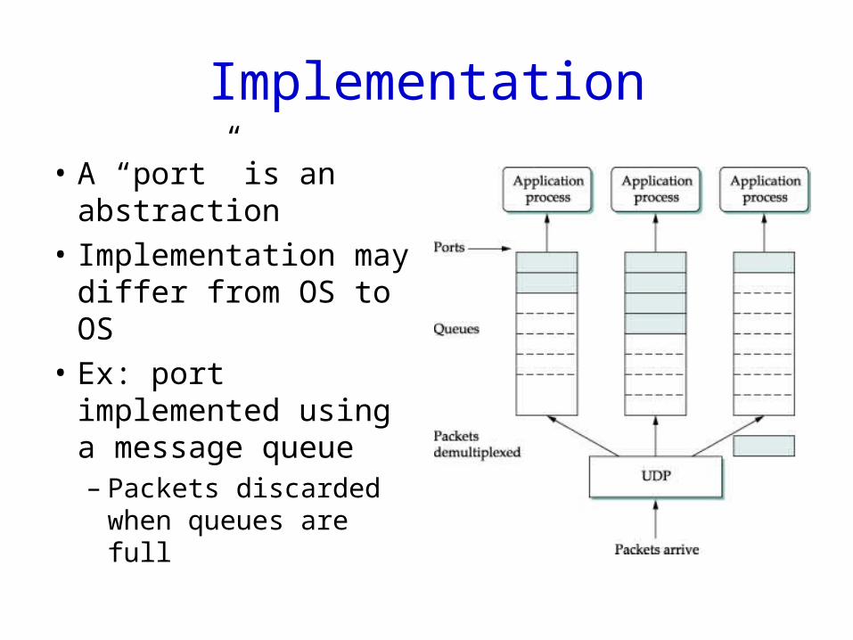
Implementation
• A “port” is an abstraction
• Implementation may differ from OS to OS
• Ex: port implemented using a message queue– Packets discarded
when queues are full
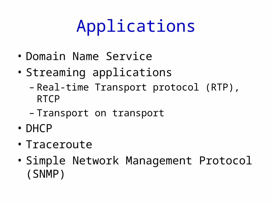
Applications
• Domain Name Service
• Streaming applications– Real-time Transport protocol (RTP), RTCP– Transport on transport
• DHCP
• Traceroute
• Simple Network Management Protocol (SNMP)
Transport Control Protocol (TCP)
-- perhaps the most widely used protocol
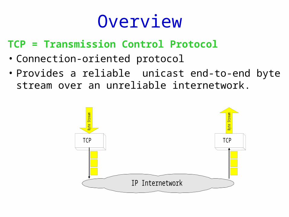
OverviewTCP = Transmission Control Protocol
• Connection-oriented protocol
• Provides a reliable unicast end-to-end byte stream over an unreliable internetwork.
TCP
IP Internetwork
Byt
e S
tream
Byt
e S
tream
TCP

Unique design challenges• We’ve learned how to reliably transmit over a direct
link– Coding/encoding, framing, sliding window
• What’s new? 1. Process-to-process communication connection setup2. Heterogeneity
– Bandwidth varies: how fast should the sender send?– RTT varies: when should a sender time out?
3. Out of order4. Resource sharing
• Many senders share a link in the middle of the network
A strawman design
• Hop-by-hop reliable transmission
• A bad idea– Can’t ensure end-to-end reliability– The end-to-end argument: a function should not
be provided at the lower levels of a system unless it can be completely and correctly implemented at that level
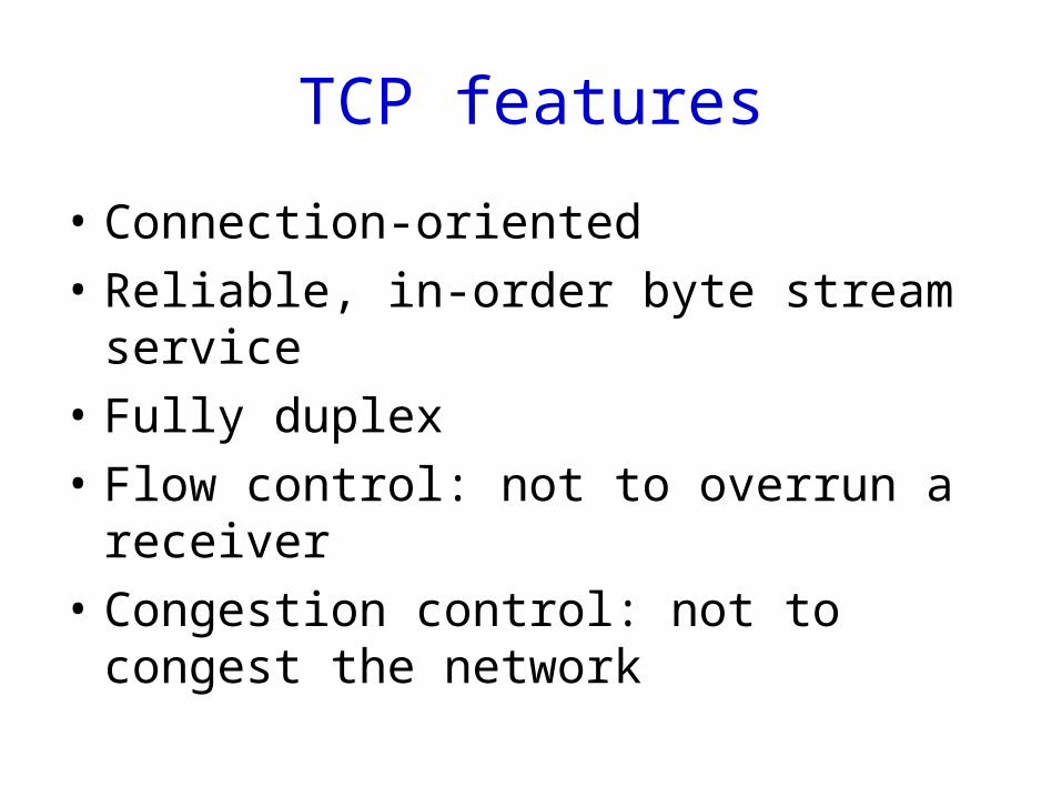
TCP features
• Connection-oriented
• Reliable, in-order byte stream service
• Fully duplex
• Flow control: not to overrun a receiver
• Congestion control: not to congest the network
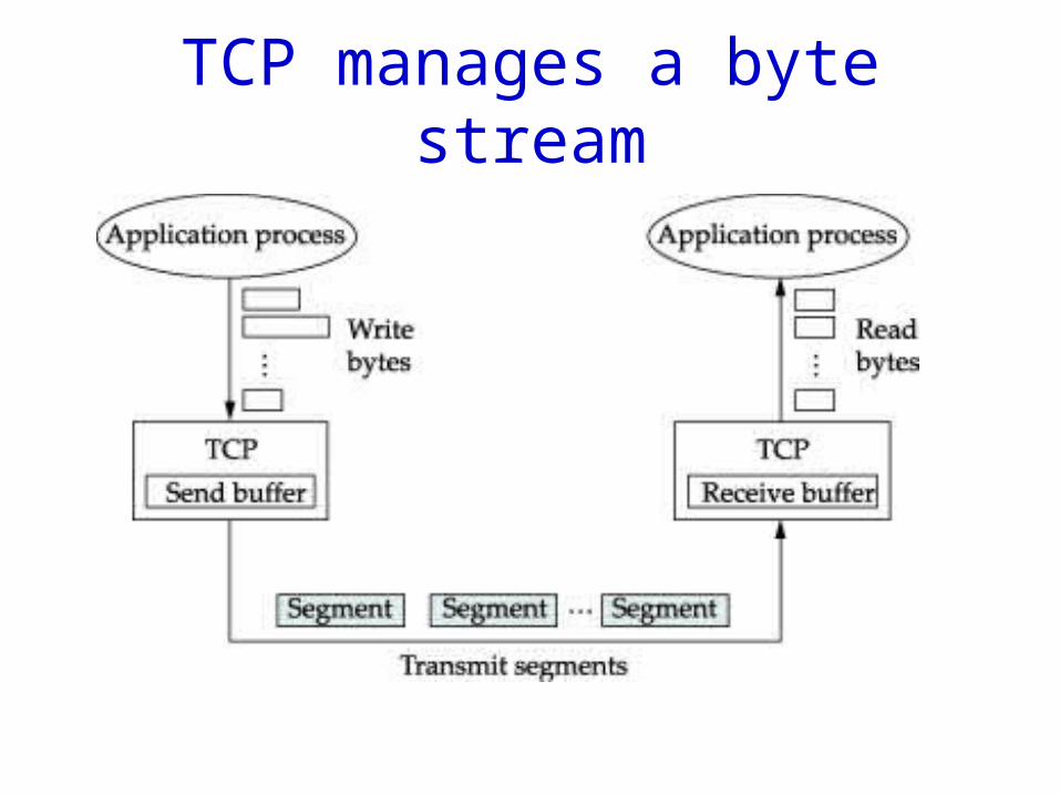
TCP manages a byte stream
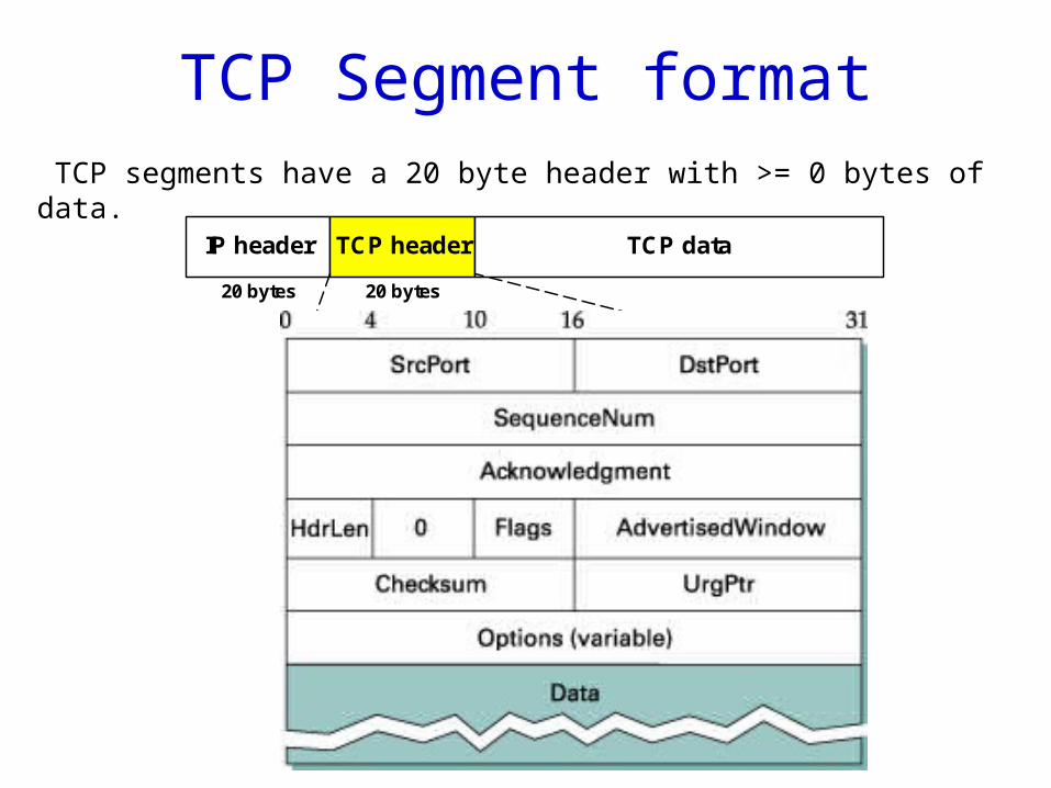
TCP Segment format
IP header TCP header TCP data
Sequence number (32 bits)
DATA
20 bytes 20 bytes
0 15 16 31
Source Port Number Destination Port Number
Acknowledgement number (32 bits)
window sizeheader length
0 Flags
Options (if any)
TCP checksum urgent pointer
20 bytes
TCP segments have a 20 byte header with >= 0 bytes of data.
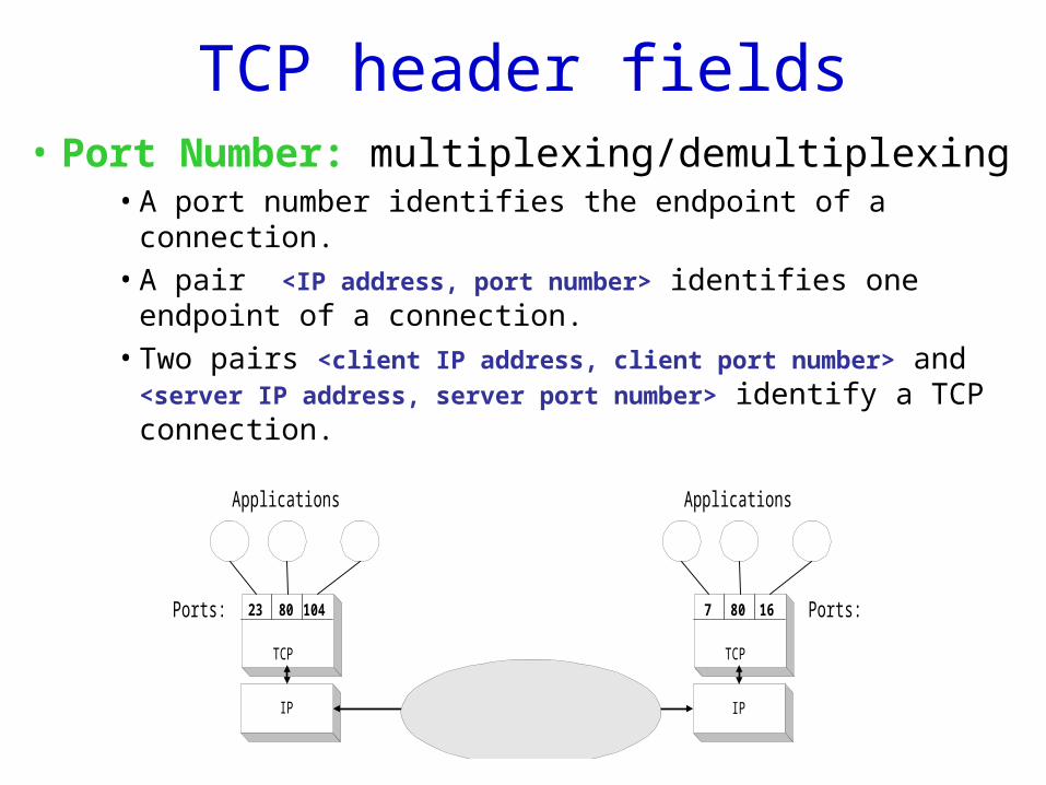
TCP header fields• Port Number: multiplexing/demultiplexing
• A port number identifies the endpoint of a connection.
• A pair <IP address, port number> identifies one endpoint of a connection.
• Two pairs <client IP address, client port number> and <server IP address, server port number> identify a TCP connection.
TCP
IP
Applications
23 10480Ports:
TCP
IP
Applications
7 1680 Ports:
TCP header fields
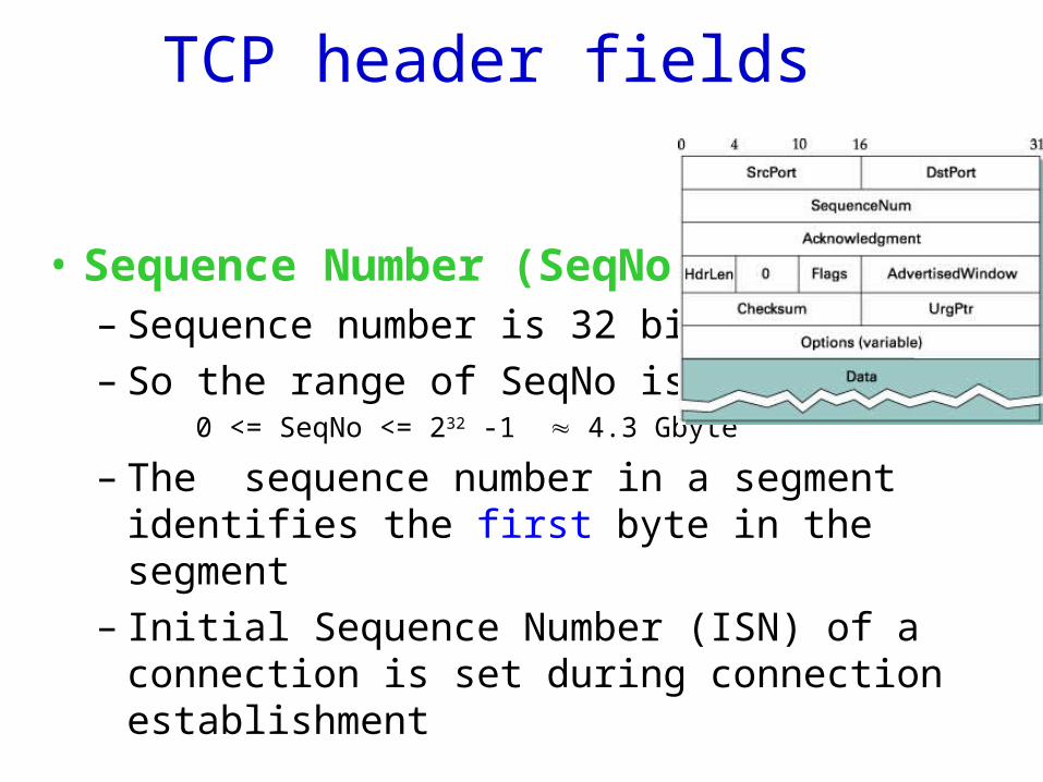
• Sequence Number (SeqNo):– Sequence number is 32 bits long. – So the range of SeqNo is
0 <= SeqNo <= 232 -1 4.3 Gbyte
– The sequence number in a segment identifies the first byte in the segment
– Initial Sequence Number (ISN) of a connection is set during connection establishment
TCP header fields
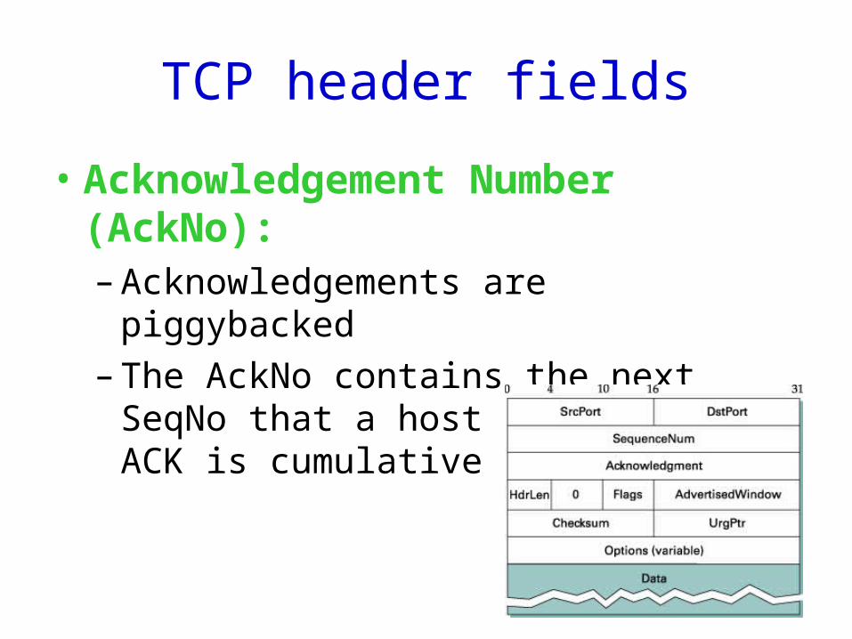
• Acknowledgement Number (AckNo):– Acknowledgements are piggybacked
– The AckNo contains the next SeqNo that a host is expectingACK is cumulative
TCP header fields
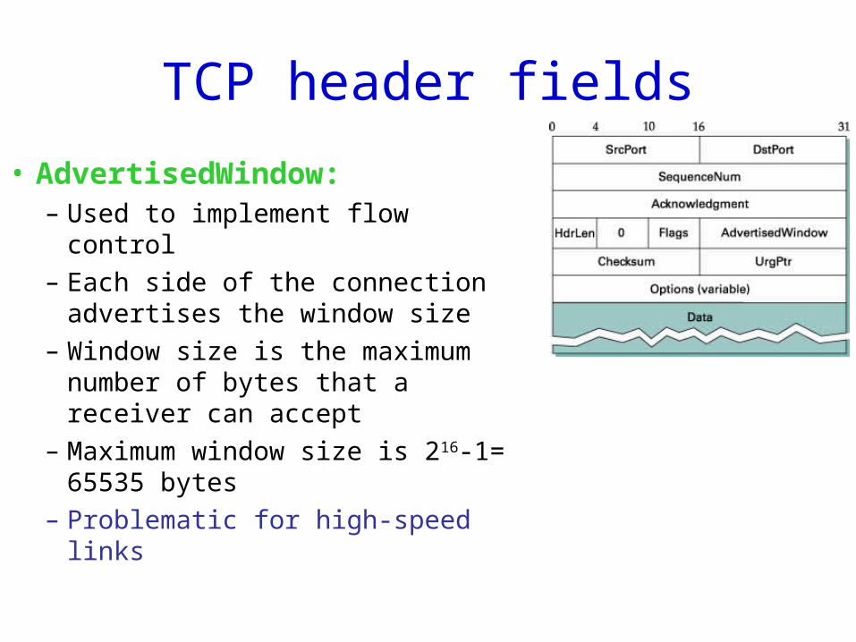
• AdvertisedWindow:– Used to implement flow control
– Each side of the connection advertises the window size
– Window size is the maximum number of bytes that a receiver can accept
– Maximum window size is 216-1= 65535 bytes
– Problematic for high-speed links
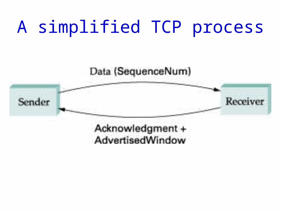
A simplified TCP process
TCP header fields
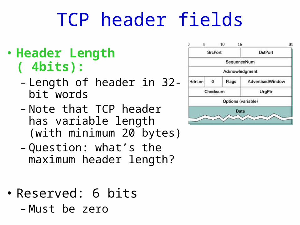
• Header Length ( 4bits):– Length of header in 32-bit
words– Note that TCP header has
variable length (with minimum 20 bytes)
– Question: what’s the maximum header length?
• Reserved: 6 bits– Must be zero
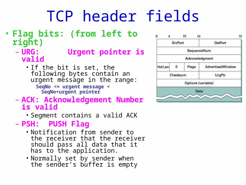
TCP header fields• Flag bits: (from left to right)
– URG: Urgent pointer is valid
• If the bit is set, the following bytes contain an urgent message in the range:
SeqNo <= urgent message < SeqNo+urgent pointer
– ACK: Acknowledgement Number is valid
• Segment contains a valid ACK– PSH: PUSH Flag
• Notification from sender to the receiver that the receiver should pass all data that it has to the application.
• Normally set by sender when the sender’s buffer is empty
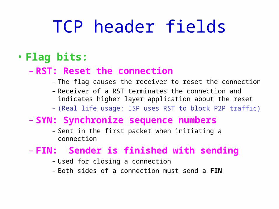
TCP header fields
• Flag bits:– RST: Reset the connection
– The flag causes the receiver to reset the connection
– Receiver of a RST terminates the connection and indicates higher layer application about the reset
– (Real life usage: ISP uses RST to block P2P traffic)
– SYN: Synchronize sequence numbers– Sent in the first packet when initiating a connection
– FIN: Sender is finished with sending– Used for closing a connection
– Both sides of a connection must send a FIN
TCP header fields
• TCP Checksum:– TCP checksum covers over both TCP header
and TCP data, and a pseudo-header (see next slide)
• Urgent Pointer:– Only valid if URG flag is set
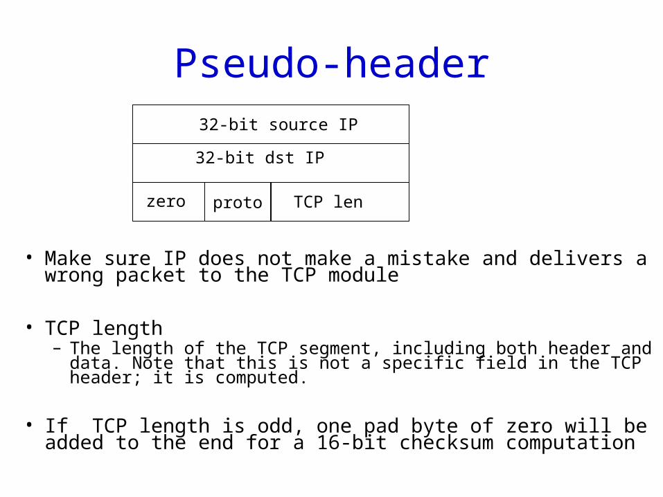
Pseudo-header
• Make sure IP does not make a mistake and delivers a wrong packet to the TCP module
• TCP length– The length of the TCP segment, including both header and data. Note
that this is not a specific field in the TCP header; it is computed.
• If TCP length is odd, one pad byte of zero will be added to the end for a 16-bit checksum computation
proto
32-bit source IP
32-bit dst IP
zero TCP len
Connection Management in TCP
• Opening a TCP Connection
• Closing a TCP Connection
• State Diagram
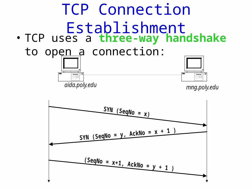
TCP Connection Establishment• TCP uses a three-way handshake to open a
connection:
aida.poly.edu mng.poly.edu
SYN (SeqNo = x)
SYN (SeqNo = y, AckNo = x + 1 )
(SeqNo = x+1, AckNo = y + 1 )
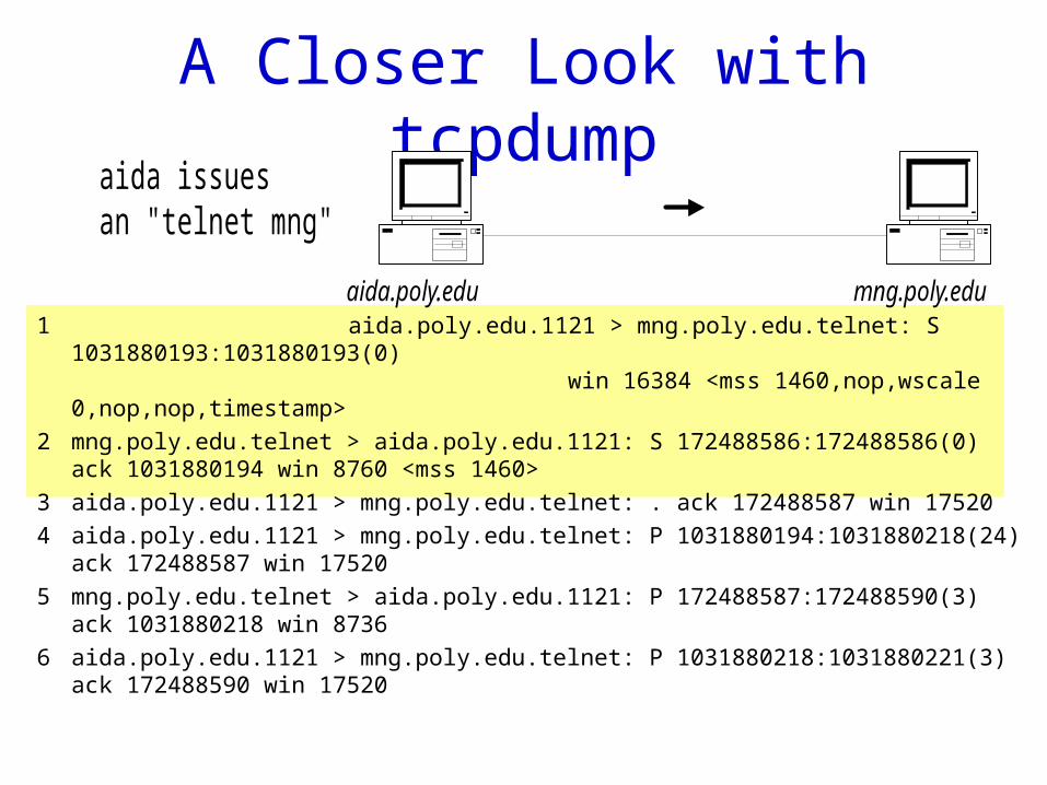
A Closer Look with tcpdump
1 aida.poly.edu.1121 > mng.poly.edu.telnet: S 1031880193:1031880193(0) win 16384 <mss 1460,nop,wscale 0,nop,nop,timestamp>
2 mng.poly.edu.telnet > aida.poly.edu.1121: S 172488586:172488586(0) ack 1031880194 win 8760 <mss 1460>
3 aida.poly.edu.1121 > mng.poly.edu.telnet: . ack 172488587 win 17520
4 aida.poly.edu.1121 > mng.poly.edu.telnet: P 1031880194:1031880218(24) ack 172488587 win 17520
5 mng.poly.edu.telnet > aida.poly.edu.1121: P 172488587:172488590(3) ack 1031880218 win 8736
6 aida.poly.edu.1121 > mng.poly.edu.telnet: P 1031880218:1031880221(3) ack 172488590 win 17520
aida.poly.edu mng.poly.edu
aida issuesan "telnet mng"
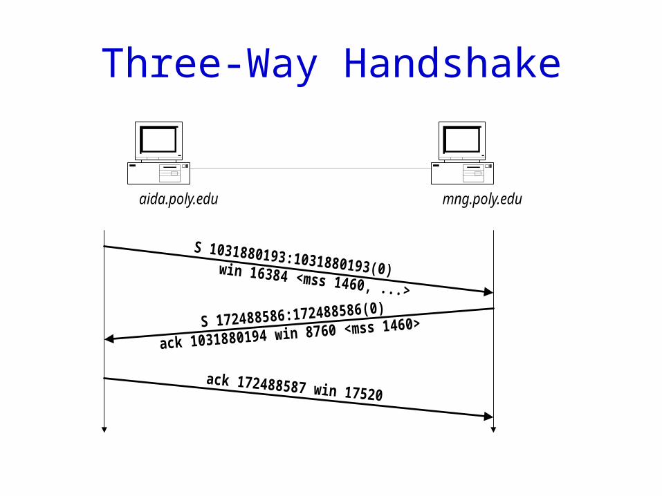
Three-Way Handshake
aida.poly.edu mng.poly.edu
S 1031880193:1031880193(0)win 16384 <mss 1460, ...>
S 172488586:172488586(0)
ack 1031880194 win 8760 <mss 1460>
ack 172488587 win 17520
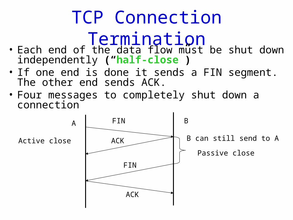
TCP Connection Termination• Each end of the data flow must be shut down
independently (“half-close”)• If one end is done it sends a FIN segment. The other
end sends ACK.• Four messages to completely shut down a connection
FIN
ACK
ACK
FIN
A B
B can still send to AActive close
Passive close
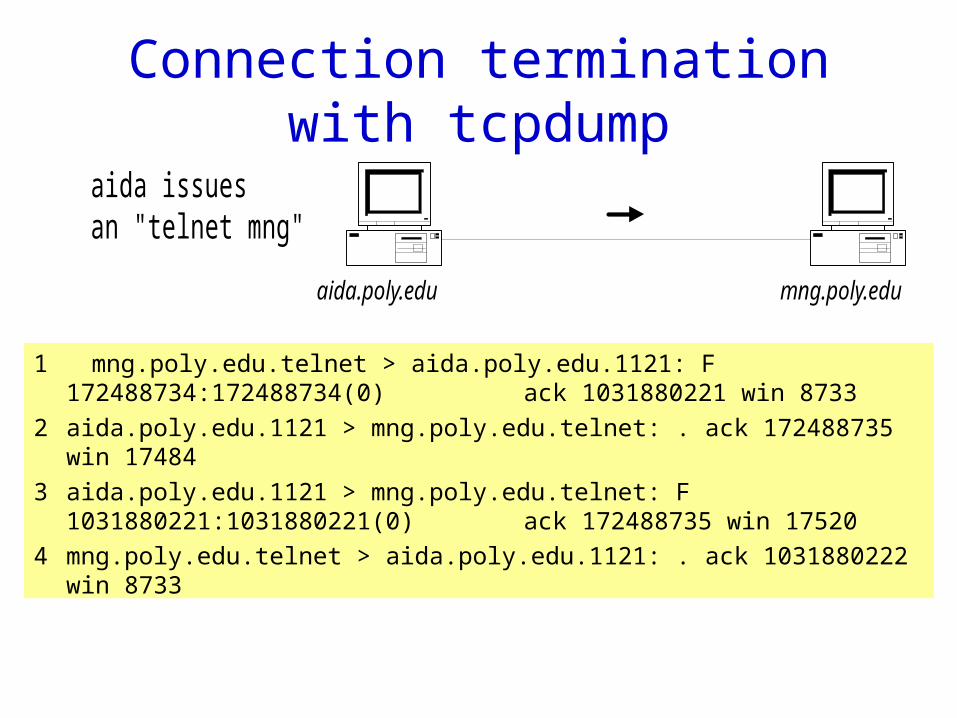
Connection termination with tcpdump
1 mng.poly.edu.telnet > aida.poly.edu.1121: F 172488734:172488734(0) ack 1031880221 win 8733
2 aida.poly.edu.1121 > mng.poly.edu.telnet: . ack 172488735 win 17484
3 aida.poly.edu.1121 > mng.poly.edu.telnet: F 1031880221:1031880221(0) ack 172488735 win 17520
4 mng.poly.edu.telnet > aida.poly.edu.1121: . ack 1031880222 win 8733
aida.poly.edu mng.poly.edu
aida issuesan "telnet mng"
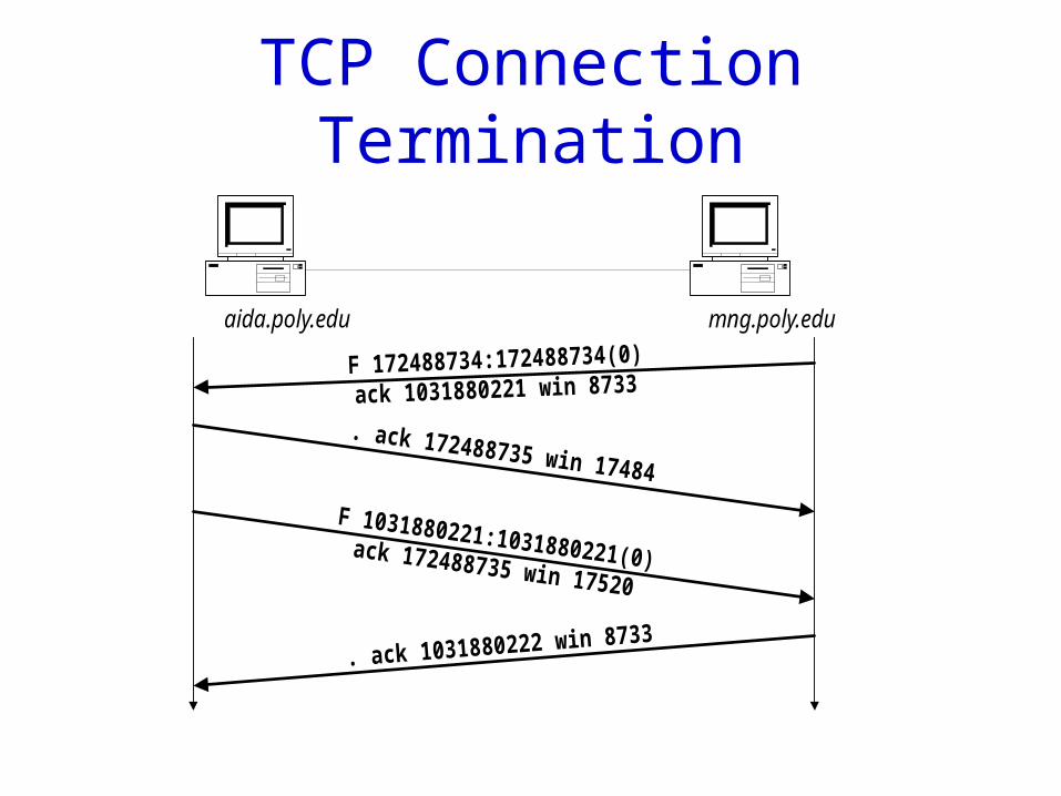
TCP Connection Termination
aida.poly.edu mng.poly.edu
F 172488734:172488734(0)
ack 1031880221 win 8733
. ack 172488735 win 17484
. ack 1031880222 win 8733
F 1031880221:1031880221(0)ack 172488735 win 17520
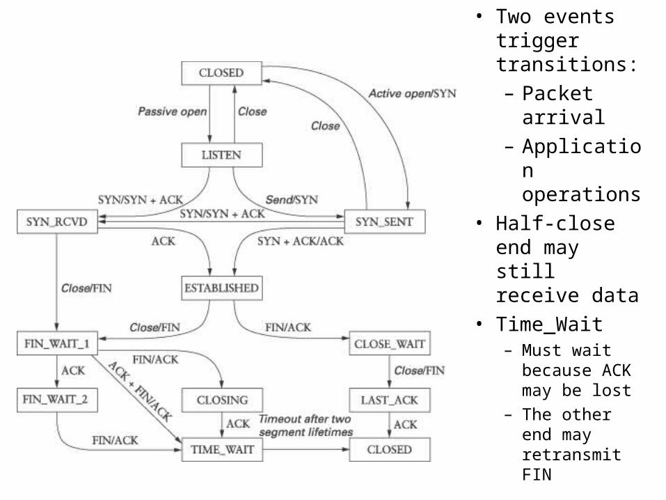
TCP state diagram
• Two events trigger transitions:
– Packet arrival
– Application operations
• Half-close end may still receive data
• Time_Wait– Must wait
because ACK may be lost
– The other end may retransmit FIN
Connection establishment/tear down
• Active/passive open
• Active/passive close, simultaneous close
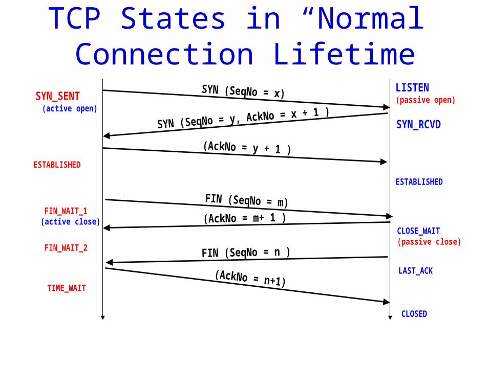
TCP States in “Normal” Connection Lifetime
SYN (SeqNo = x)
SYN (SeqNo = y, AckNo = x + 1 )
(AckNo = y + 1 )
SYN_SENT(active open)
SYN_RCVD
ESTABLISHED
ESTABLISHED
FIN_WAIT_1(active close)
LISTEN(passive open)
FIN (SeqNo = m)
CLOSE_WAIT(passive close)
(AckNo = m+ 1 )
FIN (SeqNo = n )
(AckNo = n+1)LAST_ACK
FIN_WAIT_2
TIME_WAIT
CLOSED
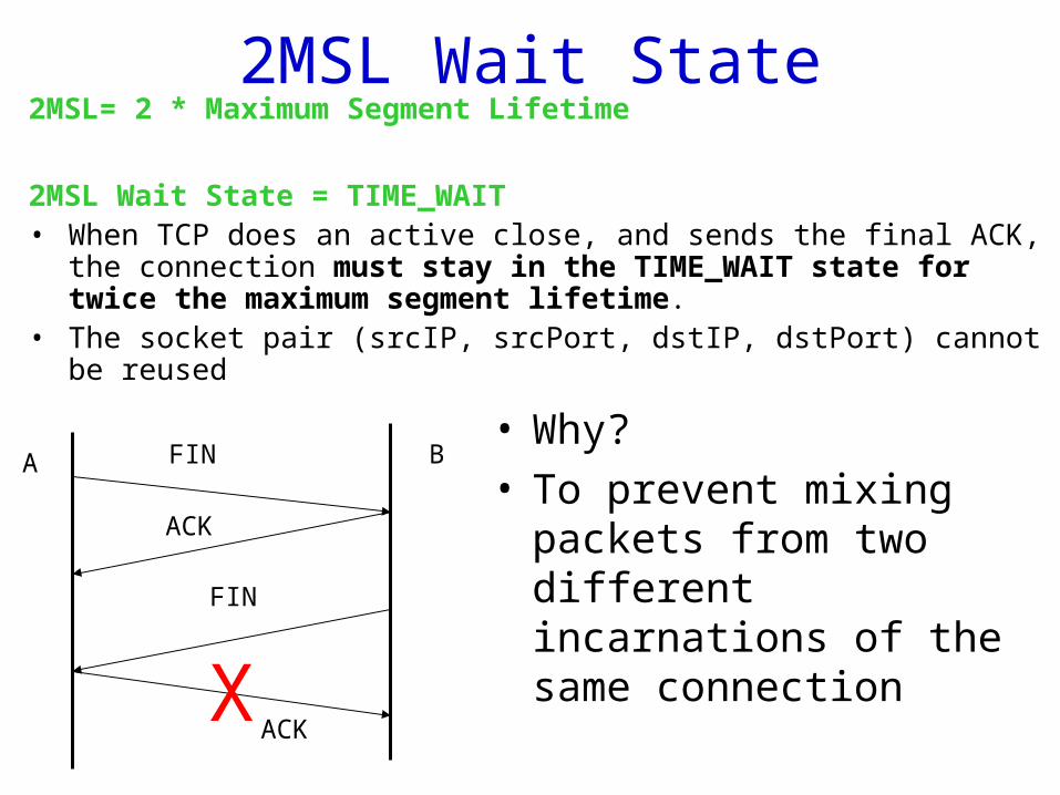
2MSL Wait State2MSL= 2 * Maximum Segment Lifetime
2MSL Wait State = TIME_WAIT• When TCP does an active close, and sends the final ACK, the connection must
stay in the TIME_WAIT state for twice the maximum segment lifetime.• The socket pair (srcIP, srcPort, dstIP, dstPort) cannot be reused
• Why? • To prevent mixing packets
from two different incarnations of the same connection
FIN
ACK
ACK
FIN
A B
X
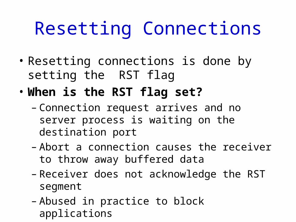
Resetting Connections
• Resetting connections is done by setting the RST flag
• When is the RST flag set?– Connection request arrives and no server process is
waiting on the destination port– Abort a connection causes the receiver to throw
away buffered data– Receiver does not acknowledge the RST segment– Abused in practice to block applications
Summary
• IP address exhaustion – IPv6– Network address translation
• TCP– Segment format– Connection establish and termination
• Next: continue on TCP
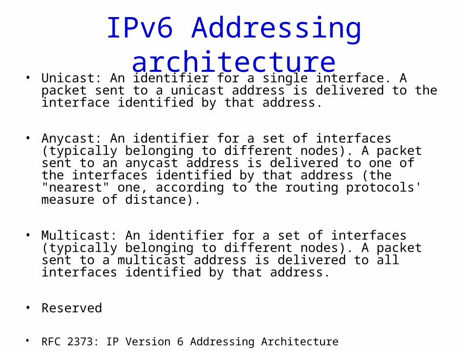
IPv6 Addressing architecture• Unicast: An identifier for a single interface. A packet sent to a unicast
address is delivered to the interface identified by that address.
• Anycast: An identifier for a set of interfaces (typically belonging to different nodes). A packet sent to an anycast address is delivered to one of the interfaces identified by that address (the "nearest" one, according to the routing protocols' measure of distance).
• Multicast: An identifier for a set of interfaces (typically belonging to different nodes). A packet sent to a multicast address is delivered to all interfaces identified by that address.
• Reserved
• RFC 2373: IP Version 6 Addressing Architecture
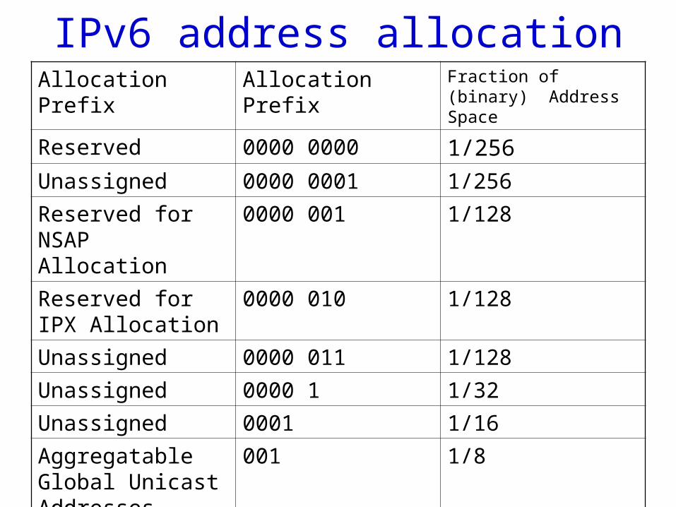
IPv6 address allocationAllocation Prefix Allocation Prefix Fraction of (binary)
Address Space
Reserved 0000 0000 1/256
Unassigned 0000 0001 1/256
Reserved for NSAP Allocation
0000 001 1/128
Reserved for IPX Allocation
0000 010 1/128
Unassigned 0000 011 1/128
Unassigned 0000 1 1/32
Unassigned 0001 1/16
Aggregatable Global Unicast Addresses
001 1/8
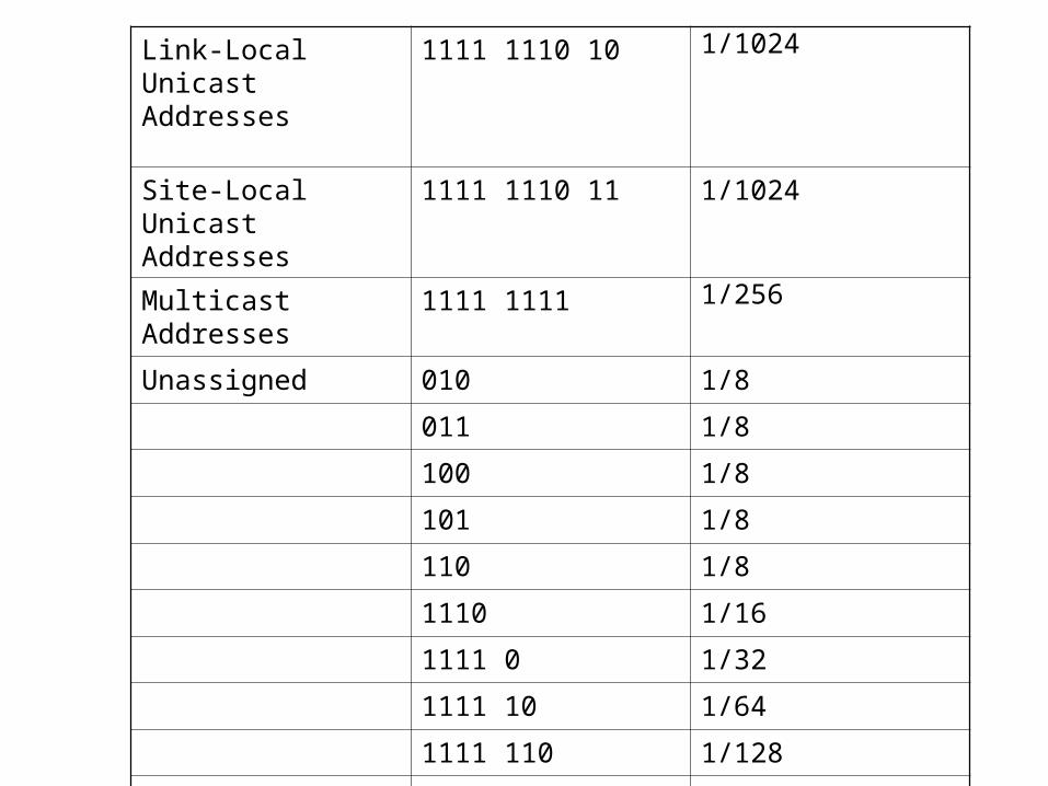
Link-Local Unicast Addresses
1111 1110 10 1/1024
Site-Local Unicast Addresses
1111 1110 11 1/1024
Multicast Addresses 1111 1111 1/256
Unassigned 010 1/8
011 1/8
100 1/8
101 1/8
110 1/8
1110 1/16
1111 0 1/32
1111 10 1/64
1111 110 1/128
1111 1110 0 1/512
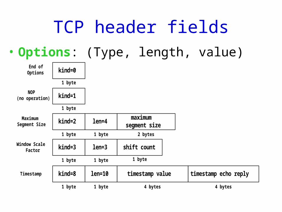
TCP header fields• Options: (Type, length, value)
End ofOptions kind=0
1 byte
NOP(no operation) kind=1
1 byte
MaximumSegment Size kind=2
1 byte
len=4
1 byte
maximumsegment size
2 bytes
Window ScaleFactor kind=3
1 byte
len=3
1 byte
shift count
1 byte
Timestamp kind=8
1 byte
len=10
1 byte
timestamp value
4 bytes
timestamp echo reply
4 bytes
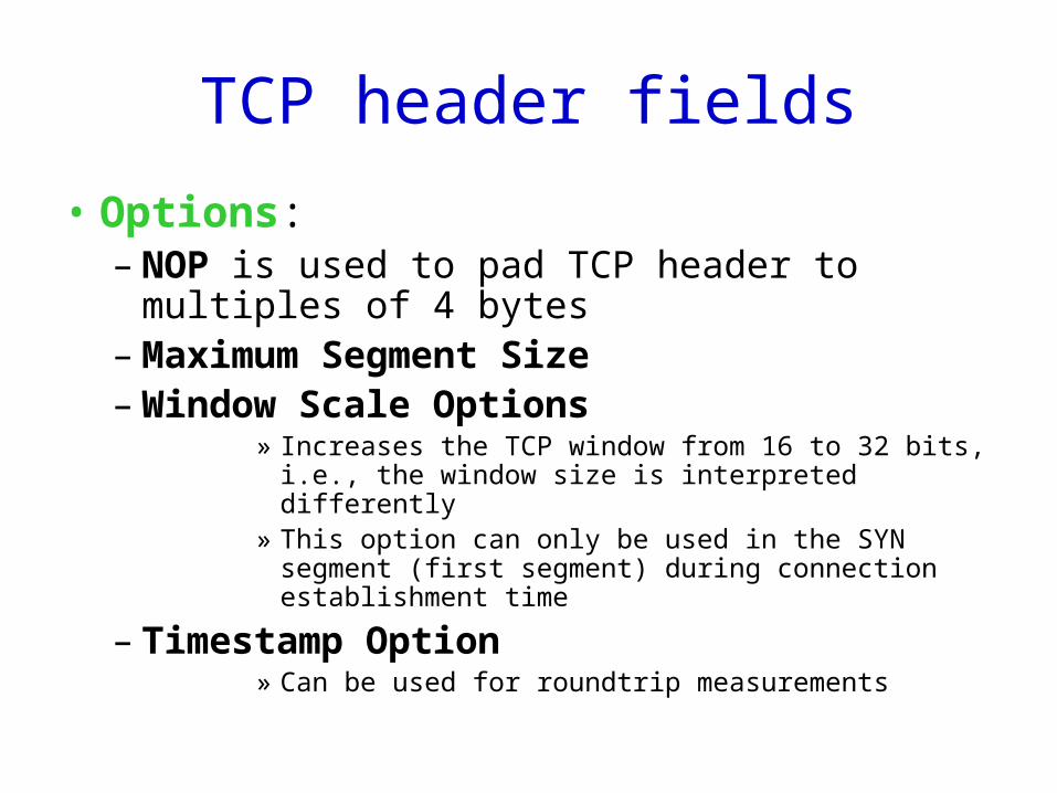
TCP header fields
• Options: – NOP is used to pad TCP header to multiples of 4
bytes– Maximum Segment Size– Window Scale Options
» Increases the TCP window from 16 to 32 bits, i.e., the window size is interpreted differently
» This option can only be used in the SYN segment (first segment) during connection establishment time
– Timestamp Option» Can be used for roundtrip measurements


![CompSci 356: Introduction to Computer Networks Lecture 3: Hardware and physical links Chap 1.4, 2 of [PD] Xiaowei Yang xwy@cs.duke.edu](https://img.pdfslide.net/doc/110x75/56649e405503460f94b31c94/compsci-356-introduction-to-computer-networks-lecture-3-hardware-and-physical.jpg)


![CS 356: Computer Network Architectures Lecture 11: DHCP and Dynamic Routing readings: [PD] 3.2.7, 3.3 Xiaowei Yang xwy@cs.duke.edu](https://img.pdfslide.net/doc/110x75/56649f1b5503460f94c2ffd6/cs-356-computer-network-architectures-lecture-11-dhcp-and-dynamic-routing.jpg)


![CS 356: Computer Network Architectures Lecture 14: Advanced Internetworking [PD] Chapter 4.1, 4.2 Xiaowei Yang xwy@cs.duke.edu](https://img.pdfslide.net/doc/110x75/56649c7d5503460f9493209a/cs-356-computer-network-architectures-lecture-14-advanced-internetworking.jpg)