Embed Size (px)
Citation preview

CS 843 - Distributed Computing SystemsChapter 3: Networking and Internetworking
Chin-Chih Chang, [email protected]
From Coulouris, Dollimore and Kindberg
Distributed Systems: Concepts and Design
Edition 3, © Addison-Wesley 2001

Instructor’s Guide for Coulouris, Dollimore and Kindberg Distributed Systems: Concepts and Design Edn. 3
© Addison-Wesley Publishers 2000
Basic terminology
• A communication subsystem is used to refer to the collection of hardware and software components that provide the communication facilities for a distributed system.
• Hosts are used to refer to the computers and other devices that use the network for communication purposes.
• A node is used to refer to any computer or switching device attached to a network.
• A subnet is a unit of routing and a collection of nodes that can all be reached on the same physical hardware.

Instructor’s Guide for Coulouris, Dollimore and Kindberg Distributed Systems: Concepts and Design Edn. 3
© Addison-Wesley Publishers 2000
Network Issues
• Performance – latency and data transfer rate.• Scalability – ability to cope with the growth of
connected hosts.• Reliability - error detection and correction.• Security - integrity and protection.• Mobility – accessibility without the location
constraint.• Quality of service – timely data transmission
without data loss.• Multicasting – simultaneous transmission of
messages to several recipients.

Instructor’s Guide for Coulouris, Dollimore and Kindberg Distributed Systems: Concepts and Design Edn. 3
© Addison-Wesley Publishers 2000
Performance
• Message transmission time: latency + length/data transfer rate (assuming no message fragmentation)• Total system bandwidth: Total volume of traffic that can be transferred
across the network in a given time• Data transfer rate and the total system
bandwidth of a network depends strongly on the network technology.
• Impact of High-Speed Networks - new design issues
Instructor’s Guide for Coulouris, Dollimore and Kindberg Distributed Systems: Concepts and Design Edn. 3
© Addison-Wesley Publishers 2000
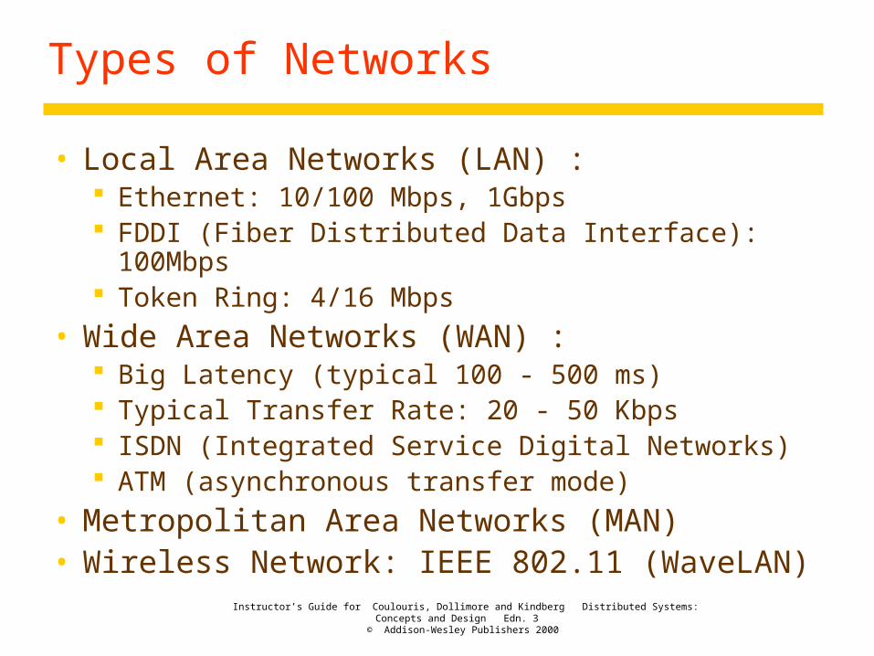
Types of Networks
• Local Area Networks (LAN) : Ethernet: 10/100 Mbps, 1Gbps FDDI (Fiber Distributed Data Interface): 100Mbps Token Ring: 4/16 Mbps
• Wide Area Networks (WAN) : Big Latency (typical 100 - 500 ms) Typical Transfer Rate: 20 - 50 Kbps ISDN (Integrated Service Digital Networks) ATM (asynchronous transfer mode)
• Metropolitan Area Networks (MAN)• Wireless Network: IEEE 802.11 (WaveLAN)

Instructor’s Guide for Coulouris, Dollimore and Kindberg Distributed Systems: Concepts and Design Edn. 3
© Addison-Wesley Publishers 2000
Figure 3.1Network types
Range Bandwidth (Mbps) Latency (ms)
LAN 1-2 kms 10-1000 1-10WAN worldwide 0.010-600 100-500MAN 2-50 kms 1-150 10Wireless LAN 0.15-1.5 km 2-11 5-20Wireless WAN worldwide 0.010-2 100-500Internet worldwide 0.010-2 100-500

Instructor’s Guide for Coulouris, Dollimore and Kindberg Distributed Systems: Concepts and Design Edn. 3
© Addison-Wesley Publishers 2000
Network Principles
• Packet transmission – messages are transmitted in packets.
• Switching schemes – schemes are required to transmit between two arbitrary nodes.
• Protocols – a well-known set of rules and formats used for communication.
• Routing – decision where to forward the packet.• Congestion control – control of the incoming
transfer rate.• Internetworking – integration of subnets.

Instructor’s Guide for Coulouris, Dollimore and Kindberg Distributed Systems: Concepts and Design Edn. 3
© Addison-Wesley Publishers 2000
Switching schemes
• Broadcast – Everything is transmitted to every node.
• Circuit switching – Communication circuits are built by making and breaking wire.
• Packet switching – Messages are packed in a packet being stored and forwarded to their destination.
• Frame relay – Switch small packets (frames) on the fly.

Instructor’s Guide for Coulouris, Dollimore and Kindberg Distributed Systems: Concepts and Design Edn. 3
© Addison-Wesley Publishers 2000
Protocols
• Protocol is a well known set of rules and formats to be used for communication between processes.
• Protocols specify both data format and the exchange mechanism (sequence of messages).
• A protocol layer represents a layer of network software (Fig. 3.2).
• Each layer encapsulate the data in the format specified for that layer (Fig. 3.3).
• A complete set of protocol layers is referred to as a protocol suite or a protocol stack.

Instructor’s Guide for Coulouris, Dollimore and Kindberg Distributed Systems: Concepts and Design Edn. 3
© Addison-Wesley Publishers 2000
Figure 3.2Conceptual layering of protocol software
Layer n
Layer 2
Layer 1
Message sent Message received
Communicationmedium
Sender Recipient

Instructor’s Guide for Coulouris, Dollimore and Kindberg Distributed Systems: Concepts and Design Edn. 3
© Addison-Wesley Publishers 2000
Figure 3.3Encapsulation as it is applied in layered protocols
Presentation header
Application-layer message
Session header
Transport header
Network header

Instructor’s Guide for Coulouris, Dollimore and Kindberg Distributed Systems: Concepts and Design Edn. 3
© Addison-Wesley Publishers 2000
Protocols
• Figure 3.4 shows a protocol stack that conforms to the seven-layer Reference Model for open systems interconnection (OSI) adopted by ISO.
• The purpose of each level in the OSI Reference Model is summarized in Fig. 3.5. It is a framework for the definition of protocols.
• The application, presentation and session layers are not clearly distinguished.
• The session layer is integrated with the transport layer.

Instructor’s Guide for Coulouris, Dollimore and Kindberg Distributed Systems: Concepts and Design Edn. 3
© Addison-Wesley Publishers 2000
Figure 3.4Protocol layers in the ISO Open Systems Interconnection (OSI) model
Application
Presentation
Session
Transport
Network
Data link
Physical
Message sent Message received
Sender Recipient
Layers
Communicationmedium

Instructor’s Guide for Coulouris, Dollimore and Kindberg Distributed Systems: Concepts and Design Edn. 3
© Addison-Wesley Publishers 2000
OSI 7 Layer Reference Model
• Physical - transmission of raw bits over a communication channel
• Data Link - reliable transmission of a block of data (frame)
• Network - routing a packet from the source to the destination (packet)
• Transport - logical communication channel between processes (message)
• Session - dialog control between end applications• Presentation - data format translation• Application - eg. ftp, telnet, Netscape, and etc.

Instructor’s Guide for Coulouris, Dollimore and Kindberg Distributed Systems: Concepts and Design Edn. 3
© Addison-Wesley Publishers 2000
Figure 3.5OSI protocol summary
Layer Description ExamplesApplication Protocols that are designed to meet the communication requirements of
specific applications, often defining the interface to a service. HTTP, FTP, SMTP,CORBA IIOP
Presentation Protocols at this level transmit data in a network representation that isindependent of the representations used in individual computers, which maydiffer. Encryption is also performed in this layer, if required.
Secure Sockets(SSL),CORBA DataRep.
Session At this level reliability and adaptation are performed, such as detection offailures and automatic recovery.
Transport This is the lowest level at which messages (rather than packets) are handled.Messages are addressed to communication ports attached to processes,Protocols in this layer may be connection-oriented or connectionless.
TCP, UDP
Network Transfers data packets between computers in a specific network. In a WANor an internetwork this involves the generation of a route passing throughrouters. In a single LAN no routing is required.
IP, ATM virtualcircuits
Data link Responsible for transmission of packets between nodes that are directlyconnected by a physical link. In a WAN transmission is between pairs ofrouters or between routers and hosts. In a LAN it is between any pair of hosts.
Ethernet MAC,ATM cell transfer,PPP
Physical The circuits and hardware that drive the network. It transmits sequences ofbinary data by analogue signalling, using amplitude or frequency modulationof electrical signals (on cable circuits), light signals (on fibre optic circuits)or other electromagnetic signals (on radio and microwave circuits).
Ethernet base- bandsignalling, ISDN

Instructor’s Guide for Coulouris, Dollimore and Kindberg Distributed Systems: Concepts and Design Edn. 3
© Addison-Wesley Publishers 2000
Protocols
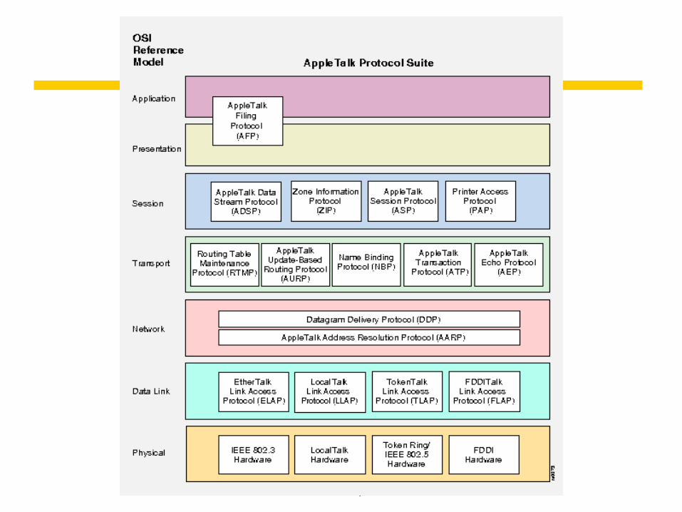
• Internetwork protocol suites include an application layer, a transport layer and an internetwork layer (Fig. 3.6).
• The AppleTalk Data Stream Protocol (ADSP) is a session layer protocol in the AppleTalk protocol suite that establishes and maintains full-duplex communication between two AppleTalk sockets.
• The session layer protocol of the WAP suit is called the Wireless Session Protocol (WSP).

Instructor’s Guide for Coulouris, Dollimore and Kindberg Distributed Systems: Concepts and Design Edn. 3
© Addison-Wesley Publishers 2000
Figure 3.6Internetwork layers
Underlying network
Application
Network interface
Transport
Internetwork
Internetwork packets
Network-specific packets
MessageLayers
Internetworkprotocols
Underlyingnetworkprotocols
Instructor’s Guide for Coulouris, Dollimore and Kindberg Distributed Systems: Concepts and Design Edn. 3
© Addison-Wesley Publishers 2000

Instructor’s Guide for Coulouris, Dollimore and Kindberg Distributed Systems: Concepts and Design Edn. 3
© Addison-Wesley Publishers 2000
Packet assembly
• Transport layer usually handles assembly and reassembly
• Packets consist of a header and a data.• If the data > MTU (maximum transfer unit), must
be divided into multiple packets with sequence number.
• MTU for IP packets = 64KB• MTU for Ethernet = 1500B

Instructor’s Guide for Coulouris, Dollimore and Kindberg Distributed Systems: Concepts and Design Edn. 3
© Addison-Wesley Publishers 2000
Ports, Addressing
• The transport layer’s task is to provide a network-independent message transport service between pairs of network ports.
• Ports are software-definable destination points for communication within a host computer.
• A transport address is network address of host + port number.
• A network address is a numeric identifier that uniquely identifies a host computer.
• In the Internet every host computer is assigned an IP number.

Instructor’s Guide for Coulouris, Dollimore and Kindberg Distributed Systems: Concepts and Design Edn. 3
© Addison-Wesley Publishers 2000
Addressing
• There are typically several ports at each host computer with well-know numbers, each allocated to a given Internet service such as HTTP or FTP. Refer to /etc/services.
• Well-known port number and service definitions are registered at www.iana.org.
• Port numbers above 1023 are available for general use by new services and by client processes.

Instructor’s Guide for Coulouris, Dollimore and Kindberg Distributed Systems: Concepts and Design Edn. 3
© Addison-Wesley Publishers 2000
Comparisons
• Reliable vs. Unreliable Communications : Packet Damage Packet Lost (congestion, bad delivery) Packet Out of Order
• Connection-oriented vs. Connectionless Communications : Connection-oriented -- establish connection, stream data
transfer, close connection TCP (Transport Control Protocol) -- reliable stream-based
communication Connectionless -- send/receive message (datagram) at any time UDP (User Datagram Protocol) -- unreliable datagram-based
communication

Instructor’s Guide for Coulouris, Dollimore and Kindberg Distributed Systems: Concepts and Design Edn. 3
© Addison-Wesley Publishers 2000
Packet delivery, Routing
• Two approaches to delivery in the network layer: Datagram delivery (IP) Virtual circuit packet delivery (ATM)
• The determination of routes for the transmission of packets to their destinations is the responsibility of a routing algorithm.
• Routing Algorithm has two parts: decide the route for each packet update knowledge of the network

Instructor’s Guide for Coulouris, Dollimore and Kindberg Distributed Systems: Concepts and Design Edn. 3
© Addison-Wesley Publishers 2000
Figure 3.7Routing in a wide area network
Hosts Linksor local networks
A
D E
B
C
1
2
5
43
6
Routers

Instructor’s Guide for Coulouris, Dollimore and Kindberg Distributed Systems: Concepts and Design Edn. 3
© Addison-Wesley Publishers 2000
Routing
• Linkstate algorithm: keep a distance vector for destinations in routing
table send a summary of routing table to neighbors using
RIP (router information protocol) read tables from neighbors and update as needed
• The RIP routing algorithm is shown in Fig. 3.9.

Instructor’s Guide for Coulouris, Dollimore and Kindberg Distributed Systems: Concepts and Design Edn. 3
© Addison-Wesley Publishers 2000
Figure 3.8Routing tables for the network in Figure 3.7
Routings from D Routings from E
To Link Cost To Link CostABCDE
336
local6
12201
ABCDE
4456
local
21110
Routings from A Routings from B Routings from C
To Link Cost To Link Cost To Link CostABCDE
local1131
01212
ABCDE
1local
214
10121
ABCDE
22
local55
21021

Instructor’s Guide for Coulouris, Dollimore and Kindberg Distributed Systems: Concepts and Design Edn. 3
© Addison-Wesley Publishers 2000
Figure 3.9Pseudo-code for RIP routing algorithm
Send: Each t seconds or when Tl changes, send Tl on each non-faulty outgoing link.Receive: Whenever a routing table Tr is received on link n:
for all rows Rr in Tr {if (Rr.link | n) {
Rr.cost = Rr.cost + 1;Rr.link = n;if (Rr.destination is not in Tl) add Rr to Tl; // add new destination to Tlelse for all rows Rl in Tl {
if (Rr.destination = Rl.destination and (Rr.cost < Rl.cost or Rl.link = n))
Rl = Rr;// Rr.cost < Rl.cost : remote node has better route// Rl.link = n : remote node is more authoritative
}}
}

Instructor’s Guide for Coulouris, Dollimore and Kindberg Distributed Systems: Concepts and Design Edn. 3
© Addison-Wesley Publishers 2000
RIP, Congestion control
• RIP routing algorithm details: t is typically 30 seconds when a faulty link is detected, cost is set to infinity costs can be based on bandwidth rather than hops slow convergence and loops are a problem
• Congestion control is achieved by informing nodes along a route that congestion has occurred, and their rate of packet transmission should be reduced.

Instructor’s Guide for Coulouris, Dollimore and Kindberg Distributed Systems: Concepts and Design Edn. 3
© Addison-Wesley Publishers 2000
Internetworking terminology
• Internetworking devices: Router/Gateway - connects to at least two networks
(network/packet level) Bridge – links networks of different type (datalink/frame level) Repeater – physical/electronic signal level Brouter – the bridge and router combination
• Switch – interconnects several separate Ethernets. A type of bridge.
• Hub – connects hosts and extends segments of Ethernet. A type of repeater.
• Tunnel – is used to hold an alien protocol on the underlying protocol. IPv6 packets are encapsulated in IPv4 and transported over the
IPv4 networks.

Instructor’s Guide for Coulouris, Dollimore and Kindberg Distributed Systems: Concepts and Design Edn. 3
© Addison-Wesley Publishers 2000
Figure 3.10Simplified view of the QMW Computer Science network
file
compute
dialup
hammer
henry
hotpoint
138.37.88.230
138.37.88.162
bruno138.37.88.249
router/sickle
138.37.95.241138.37.95.240/29
138.37.95.249
copper138.37.88.248
firewall
web
138.37.95.248/29
server
desktop computers 138.37.88.xx
subnet
subnet
Eswitch
138.37.88
server
server
server
138.37.88.251
custard138.37.94.246
desktop computers
Eswitch
138.37.94
hubhub
Student subnetStaff subnet
otherservers
router/firewall
138.37.94.251
1000 Mbps EthernetEswitch: Ethernet switch
100 Mbps Ethernet
file server/gateway
printers
Campusrouter
Campusrouter
138.37.94.xx

Instructor’s Guide for Coulouris, Dollimore and Kindberg Distributed Systems: Concepts and Design Edn. 3
© Addison-Wesley Publishers 2000
Figure 3.11Tunnelling for IPv6 migration
A BIPv6 IPv6
IPv6 encapsulated in IPv4 packets
Encapsulators
IPv4 network
Instructor’s Guide for Coulouris, Dollimore and Kindberg Distributed Systems: Concepts and Design Edn. 3
© Addison-Wesley Publishers 2000
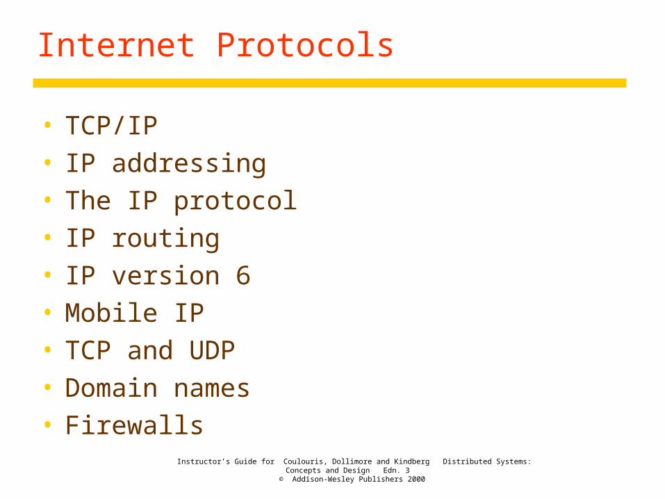
Internet Protocols
• TCP/IP• IP addressing• The IP protocol• IP routing• IP version 6• Mobile IP• TCP and UDP• Domain names• Firewalls

Instructor’s Guide for Coulouris, Dollimore and Kindberg Distributed Systems: Concepts and Design Edn. 3
© Addison-Wesley Publishers 2000
TCP/IP
• TCP stands for Transmission Control Protocol. IP stands for Internet Protocol.
• Many application services and application-level protocols exist based on TCP/IP: The Web – HyperText Transfer Protocol (HTTP) E-mail – Simple Mail Transfer Protocol (SMTP), Post Office
Protocol (POP) Netnews – Network News Transfer Protocol (NNTP) File transfer – File Transfer Protocol (FTP), Telnet
• HTTP is usually transported by the direct use of TCP, but when end-to-end security is required, the Transport Layer Security (TLS) or Secure Sockets Layer (SSL) protocol is layered on top of TCP.

Instructor’s Guide for Coulouris, Dollimore and Kindberg Distributed Systems: Concepts and Design Edn. 3
© Addison-Wesley Publishers 2000
TCP/IP
• The only significant exceptions of the universal adoption of TCP/IP communication are: The use of WAP for wireless applications on portable
devices; Special protocols to support multimedia streaming
applications.
• The general illustration of internetwork protocol layers of Figure 3.6 is translated into the specific Internet case in Figure 3.12.
• There are two transport protocols – TCP (Transport/Transmission Control Protocol) and UDP (User Datagram Protocol).

Instructor’s Guide for Coulouris, Dollimore and Kindberg Distributed Systems: Concepts and Design Edn. 3
© Addison-Wesley Publishers 2000
Figure 3.12TCP/IP layers
Messages (UDP) or Streams (TCP)
Application
Transport
Internet
UDP or TCP packets
IP datagrams
Network-specific frames
MessageLayers
Underlying network
Network interface
Instructor’s Guide for Coulouris, Dollimore and Kindberg Distributed Systems: Concepts and Design Edn. 3
© Addison-Wesley Publishers 2000
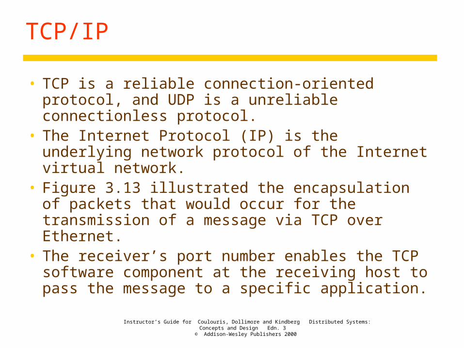
TCP/IP
• TCP is a reliable connection-oriented protocol, and UDP is a unreliable connectionless protocol.
• The Internet Protocol (IP) is the underlying network protocol of the Internet virtual network.
• Figure 3.13 illustrated the encapsulation of packets that would occur for the transmission of a message via TCP over Ethernet.
• The receiver’s port number enables the TCP software component at the receiving host to pass the message to a specific application.

Instructor’s Guide for Coulouris, Dollimore and Kindberg Distributed Systems: Concepts and Design Edn. 3
© Addison-Wesley Publishers 2000
Figure 3.13Encapsulation in a message transmitted via TCP over an Ethernet
Application message
TCP header
IP header
Ethernet header
Ethernet frame
port
TCP
IP

Instructor’s Guide for Coulouris, Dollimore and Kindberg Distributed Systems: Concepts and Design Edn. 3
© Addison-Wesley Publishers 2000
TCP/IP
• The TCP/IP specifications do not specify the layers below the Internet datagram layer. IP packets in the Internet layer are transformed into packets for transmission over any combination of underlying networks or data links.
• For example, IP ran initially over the ARPANET. Today it is used over every known network technology, including ATM, Ethernets, token ring, and PPP.

Instructor’s Guide for Coulouris, Dollimore and Kindberg Distributed Systems: Concepts and Design Edn. 3
© Addison-Wesley Publishers 2000
TCP/IP
• The success of TCP/IP is based on their independence of the underlying transmission technology.
• Users and application programs perceive a single virtual network supporting TCP and UDP as shown in Figure 3.14.

Instructor’s Guide for Coulouris, Dollimore and Kindberg Distributed Systems: Concepts and Design Edn. 3
© Addison-Wesley Publishers 2000
Figure 3.14The programmer's conceptual view of a TCP/IP Internet
IP
Application Application
TCP UDP
Instructor’s Guide for Coulouris, Dollimore and Kindberg Distributed Systems: Concepts and Design Edn. 3
© Addison-Wesley Publishers 2000
TCP abstractions
• The data is the abstraction of a stream of bytes.• A connection is established before messages
are sent.• It assumes one process is the client and one is
the server in establishing a connection.• Messages are sent using handles rather than
source-destination addresses.

Instructor’s Guide for Coulouris, Dollimore and Kindberg Distributed Systems: Concepts and Design Edn. 3
© Addison-Wesley Publishers 2000
Common Internet applications that use TCP
• BGP (routing) – Border Gateway Protocol• SMTP (email) – Simple Mail Transfer Protocol• POP (email) – Post Office Protocol• Telnet (remote login)• SSH (remote login) – Secure Shell• FTP (file transfer) – File Transfer Protocl• HTTP (web) – HyperText Transfer Protocol• NNTP (netnews) - (Network News Transfer Protocol)• DNS (name service) – Domain Name Service• NFS (distributed file system) – Network File System• Sun RPC (remote procedure call)• DCE RPC (remote procedure call)

Instructor’s Guide for Coulouris, Dollimore and Kindberg Distributed Systems: Concepts and Design Edn. 3
© Addison-Wesley Publishers 2000
Internet Protocols
• IP provides an unreliable, connectionless datagram delivery service.
• IP has a facility for fragmenting datagrams into fragments and reassembling them on the receiving side.
• The rapid growth of the Internet led the development of IPv6 to overcome the addressing limitations of IPv4 and add features to support new requirements.
Instructor’s Guide for Coulouris, Dollimore and Kindberg Distributed Systems: Concepts and Design Edn. 3
© Addison-Wesley Publishers 2000
IP addressing
• The scheme used for assigning host addresses to networks and the computers connected to them had to satisfy the following requirements: Universal Efficient The addressing scheme must lend itself to the
development of a flexible and efficient routing scheme.
• The scheme chosen assigns an IP address to each host in the Internet.

Instructor’s Guide for Coulouris, Dollimore and Kindberg Distributed Systems: Concepts and Design Edn. 3
© Addison-Wesley Publishers 2000
IP addressing
• The design adopted for Internet address space is shown in Figure 3.15.
• There are four classes – A, B, C, and D. • Class D is reserved for Internet multicast.• Class E is reserved for future requirements.• These 32-bit Internet addresses containing a
network identifier (156.26.10.) and host identifier (239) are usually written as a sequence of four decimal numbers separated by dots.
• Each decimal number represents one of the four bytes, or octets of the IP address.

Instructor’s Guide for Coulouris, Dollimore and Kindberg Distributed Systems: Concepts and Design Edn. 3
© Addison-Wesley Publishers 2000
Figure 3.15Internet address structure, showing field sizes in bits
7 24
Class A: 0 Network ID Host ID
14 16
Class B: 1 0 Network ID Host ID
21 8
Class C: 1 1 0 Network ID Host ID
28
Class D (multicast): 1 1 1 0 Multicast address
27
Class E (reserved): 1 1 1 1 unused0

Instructor’s Guide for Coulouris, Dollimore and Kindberg Distributed Systems: Concepts and Design Edn. 3
© Addison-Wesley Publishers 2000
IP addressing
• The permissible values for each class of network address are shown in Figure 3.16.
• The Class A addresses, with a capacity 2^24 hosts on each subnets, are reserved for very large networks such as the US NSFNet.
• Class B addresses are allocated to organizations containing more than 255 computers such as universities.
• Class C are allocated to all other network operators.

Instructor’s Guide for Coulouris, Dollimore and Kindberg Distributed Systems: Concepts and Design Edn. 3
© Addison-Wesley Publishers 2000
Figure 3.16Decimal representation of Internet addresses
octet 1 octet 2 octet 3
Class A: 1 to 127
0 to 255 0 to 255 1 to 254
Class B: 128 to 191
Class C: 192 to 223
224 to 239 Class D (multicast):
Network ID
Network ID
Network ID
Host ID
Host ID
Host ID
Multicast address
0 to 255 0 to 255 1 to 254
0 to 255 0 to 255 0 to 255
0 to 255 0 to 255 0 to 255
Multicast address
0 to 255 0 to 255 1 to 254240 to 255 Class E (reserved):
1.0.0.0 to 127.255.255.255
128.0.0.0 to 191.255.255.255
192.0.0.0 to 223.255.255.255
224.0.0.0 to 239.255.255.255
240.0.0.0 to 255.255.255.255
Range of addresses

Instructor’s Guide for Coulouris, Dollimore and Kindberg Distributed Systems: Concepts and Design Edn. 3
© Addison-Wesley Publishers 2000
IP addressing
• Addresses with host identifier that is all set to 1 is used for the broadcast address.
• Network identifiers are allocated by the Internet Information Center (NIC).
• Around 1990 it became evident that NIC was likely to run out of IP addresses. Two steps were taken: Development of a new IP protocol. Modifying the way in which IP addresses are allocated.
Classless InterDomain Routing (CIDR) was introduced.
• Figure 3.10 shows examples of several Class C-sized subnets (using CIDR to subdivide a class B address space).

Instructor’s Guide for Coulouris, Dollimore and Kindberg Distributed Systems: Concepts and Design Edn. 3
© Addison-Wesley Publishers 2000
Comments about IP and the Internet
• IP emerged from ARPANET of the early 1970's.• It is independent of underlying hardware.• The Internet protocols usually refer to TCP/IP.• It doesn’t quite fit into OSI model.• It was developed in a much smaller scale
environment.• A lot of work has gone into tuning.• IP protocol transmits datagrams from source to
destination via intermediate routers.

Instructor’s Guide for Coulouris, Dollimore and Kindberg Distributed Systems: Concepts and Design Edn. 3
© Addison-Wesley Publishers 2000
IP protocol overview
• The main components of IP packet format is shown in Figure 3.17.
• IP protocol is an unreliable or best- effort delivery semantics.
• IP protocol has a header checksum, but no data checksum.
• IP protocol breaks up datagrams into fragments to fit MTU of underlying network
• IP protocol obtains a physical address from underlying network address resolution mechanism.

Instructor’s Guide for Coulouris, Dollimore and Kindberg Distributed Systems: Concepts and Design Edn. 3
© Addison-Wesley Publishers 2000
Figure 3.17IP packet layout
dataIP address of destinationIP address of source
header
up to 64 kilobytes

Instructor’s Guide for Coulouris, Dollimore and Kindberg Distributed Systems: Concepts and Design Edn. 3
© Addison-Wesley Publishers 2000
Address resolution
• The process to convert Internet address to a network address is called address resolution.
• Address resolution is technology dependent: Hosts connected to IP switches don't need
translation. Network addresses can be assigned dynamically. For some technologies such as Ethernet network
address is hardwired. An address resolution protocol (ARP) is required to map the IP address to the physical address.

Instructor’s Guide for Coulouris, Dollimore and Kindberg Distributed Systems: Concepts and Design Edn. 3
© Addison-Wesley Publishers 2000
Example: ARP on an Ethernet
• Each host is running ARP.• The ARP module maintains a cache of pairs: (IP
address, Ethernet address)• If the address is in the local cache, use it. If address not
in cache, broadcast a request.• The host with matching IP address responds and a new
pair is added to the local ARP cache.• What happens if no host responds to an ARP
broadcast? Ignore it.• Try the arp command.• The source (sending) address can be substituted. This
is called IP spoofing. Denial of service of Feb. 2000.

Instructor’s Guide for Coulouris, Dollimore and Kindberg Distributed Systems: Concepts and Design Edn. 3
© Addison-Wesley Publishers 2000
IP routing
• A routing protocol: decide the route for each packet update knowledge of the network
• The topological map of the Internet is partitioned into autonomous systems (AS), which are subdivided into areas.
• Fig. 3.10 shows the campus intranet as an AS.• Every AS has a backbone area.• The collection of routers which allows the non-
backbone areas to connect to the backbone area is called the backbone of the network.

Instructor’s Guide for Coulouris, Dollimore and Kindberg Distributed Systems: Concepts and Design Edn. 3
© Addison-Wesley Publishers 2000
Routing Protocols
• RIP1 (Routing Information Protocol) used the distance vector algorithm.
• RIP2 (1993) handles classless interdomain routing, better multicast and authentication.
• Open Shortest Path First (OSPF) based on Dijkstra's shortest path algorithm converges better. It is the link-state class of algorithms.
• RIP routers exchanged information every 30 seconds, during which time they didn't send out any IP packets. The remedy is to have a random value in the range 15-45 seconds.

Instructor’s Guide for Coulouris, Dollimore and Kindberg Distributed Systems: Concepts and Design Edn. 3
© Addison-Wesley Publishers 2000
Routing Scalability
• It is infeasible for every router to maintain a full routing table.
• Two possible solutions are employed: topological grouping of IP addresses the use of the default routes
• In 1993 some location dependence in IP addresses is introduced:
194.0.0.0 to 195.255.255.255 Europe 198.0.0.0 to 199.255.255.255 North America 200.0.0.0 to 201.255.255.255 Central/South America 202.0.0.0 to 195.203.255.255 Asia and Pacific

Instructor’s Guide for Coulouris, Dollimore and Kindberg Distributed Systems: Concepts and Design Edn. 3
© Addison-Wesley Publishers 2000
IP Routing
• Key routers close to backbone have more complete tables.
• The default entry specifies a route to be used for all IP packets whose destination is not included in the routing table.
• Addresses on same subnet use local address resolution. The IP layer uses ARP to get the network address.
Instructor’s Guide for Coulouris, Dollimore and Kindberg Distributed Systems: Concepts and Design Edn. 3
© Addison-Wesley Publishers 2000
CIDR
• Gateways and routers are connected to two ore more networks and they have several Internet addresses, one for each network to which they are attached.
• Try the netstat command.• The CIDR is to allocate a batch of contiguous
class C addresses to a subnet requiring more than 255 addresses.
• The CIDR scheme also subdivides a Class B address space for allocation to multiple subnets.
Instructor’s Guide for Coulouris, Dollimore and Kindberg Distributed Systems: Concepts and Design Edn. 3
© Addison-Wesley Publishers 2000
CIDR
• The CIDR uses a mask to select portion of address to be compared with routing table.
• The CIDR can use any part of address for subnet to further subdivide a subnet.
• Figure 3.10 shows the use of CIDR to split the 138.37.95 class C-sized subnet into several groups of eight host addresses.

Instructor’s Guide for Coulouris, Dollimore and Kindberg Distributed Systems: Concepts and Design Edn. 3
© Addison-Wesley Publishers 2000
IP version 6
• IPv6 (Internet Protocol Version 6) is the latest level of the Internet Protocol (IP) and is now included as part of IP support in many products including the major computer operating systems.
• IPv6 has also been called "IPng" (IP Next Generation).
• Formally, IPv6 is a set of specifications adopted by the Internet Engineering Task Force (IETF) in 1994.
• Figure 3.18 shows the layout of IPv6 headers.

Instructor’s Guide for Coulouris, Dollimore and Kindberg Distributed Systems: Concepts and Design Edn. 3
© Addison-Wesley Publishers 2000
Figure 3.18IPv6 header layout
Source address(128 bits)
Destination address(128 bits)
Version (4 bits) Priority (4 bits) Flow label (24 bits)
Payload length (16 bits) Hop limit (8 bits)Next header (8 bits)

Instructor’s Guide for Coulouris, Dollimore and Kindberg Distributed Systems: Concepts and Design Edn. 3
© Addison-Wesley Publishers 2000
IP version 6 – Address Space
• The most obvious improvement in IPv6 over the IPv4 is that IP addresses are lengthened from 32 bits to 128 bits.
• This provides 2128 addresses or 3 x 1038.• This extension anticipates considerable future
growth of the Internet.• Only 28% addresses are defined. 1/8th partition
is organized according to the geographic locations and the other according to their organizational locations.

Instructor’s Guide for Coulouris, Dollimore and Kindberg Distributed Systems: Concepts and Design Edn. 3
© Addison-Wesley Publishers 2000
IPv6 – Routing Speed
• No checksum is applied to the packet content (payload). The checksum can be done at higher levels.
• No fragmentation can occur once a packet is sent. The smallest MTU is determined before a packet is transmitted.
• Options are specified in an extension to the header that is examined only at the destination, thus speeding up overall network performance.

Instructor’s Guide for Coulouris, Dollimore and Kindberg Distributed Systems: Concepts and Design Edn. 3
© Addison-Wesley Publishers 2000
IP version 6 – Real-time and Services
• The priority and flow label fields are concerned with real-time and specific services.
• Priority values 0 to 8 are for those applications whose transmissions can be slowed. Values 8 to 15 are reserved for real-time applications.
• Flow labels enable resource to be reserved in order to meet the timing requirements of specific real-time data streams.
• The use of these facilities of IPv6 will depend on major enhancements to the infrastructure.

Instructor’s Guide for Coulouris, Dollimore and Kindberg Distributed Systems: Concepts and Design Edn. 3
© Addison-Wesley Publishers 2000
IP version 6 – Future Evolution
• The next header field provides for future evolution.
• If non-zero, it specifies an extension header type in the packet.
• The extension header types include the services for router information, route definition, fragment handling, authentication, encryption information, and destination information.
• Each extension header type has a specific size and format and is transmitted after the basic header and before the payload.

Instructor’s Guide for Coulouris, Dollimore and Kindberg Distributed Systems: Concepts and Design Edn. 3
© Addison-Wesley Publishers 2000
IPv6 – Multicast and Anycast
• IPv6 describes rules for three types of addressing: unicast (one host to one other host), anycast (one host to at least one of multiple hosts), and multicast (one host to multiple hosts).
• The introduction of an "anycast" address provides the possibility of sending a message to the nearest of several possible gateway hosts with the idea that any one of them can manage the forwarding of the packet to others.
• Anycast messages can be used to update routing tables along the line.

Instructor’s Guide for Coulouris, Dollimore and Kindberg Distributed Systems: Concepts and Design Edn. 3
© Addison-Wesley Publishers 2000
IP version 6 – Security
• The advantage of implementing security at the IP level is that it can be applied without the need for security-aware implementations of application programs.
• Security in IPv6 is implemented through the authentication and encrypted security payload extension header types , for ensuring data integrity, and for ensuring privacy.

Instructor’s Guide for Coulouris, Dollimore and Kindberg Distributed Systems: Concepts and Design Edn. 3
© Addison-Wesley Publishers 2000
MobileIP
• Dynamic Host Configuration Protocol (DHCP) enables a newly connected computer to acquire a temporary IP.
• If a mobile computer is to remain accessible to client and resource-sharing applications (such as a share-monitoring service) when moving between networks, it must retain a single IP number, but IP routing is subnet-based.
• MobileIP is a solution to allow the correct routing through different subnets.

Instructor’s Guide for Coulouris, Dollimore and Kindberg Distributed Systems: Concepts and Design Edn. 3
© Addison-Wesley Publishers 2000
MobileIP
• When a mobile host is connected outside of its home base, a home agent (HA) and a foreign agent (FA) take responsibility of rerouting.
• The HA is responsible for holding up-to-date knowledge of the mobile host’s current location.
• When a mobile host leaves its home site, it should inform the HA. During the absence it will behave as proxy for the absent host.

Instructor’s Guide for Coulouris, Dollimore and Kindberg Distributed Systems: Concepts and Design Edn. 3
© Addison-Wesley Publishers 2000
MobileIP
• Once the mobile host arrives at a new site, it informs the FA at that site. The FA allocates a temporary IP address (care-of address) on the local subnet and notifies the HA the mobile host’s home IP address and the care-of address.
• Figure 3.19 illustrates the MobileIP routing mechanism.
• An IP packet addressed to the mobile host’s home address is received at the home network and routed to the HA.

Instructor’s Guide for Coulouris, Dollimore and Kindberg Distributed Systems: Concepts and Design Edn. 3
© Addison-Wesley Publishers 2000
Figure 3.19The Mobile IP routing mechanism
Sender
Home
Mobile host MH
Foreign agent FAInternet
agent
First IP packet addressed to MH
Address of FAreturned to sender
First IP packettunnelled to FA
Subsequent IP packetstunnelled to FA

Instructor’s Guide for Coulouris, Dollimore and Kindberg Distributed Systems: Concepts and Design Edn. 3
© Addison-Wesley Publishers 2000
MobileIP
• The HA then encapsulates the IP packet in a MobileIP packet and sends it to the FA. The FA unpacks the packet and deliver it to the mobile host. This uses the tunnelling technique.
• The HA also send the care-of address of the mobile host to the original sender.
• If the sender is MobileIP enabled, the subsequent communication will directly go the new address. If it is not, it will ignore the change and continue to be routed via the HA.

Instructor’s Guide for Coulouris, Dollimore and Kindberg Distributed Systems: Concepts and Design Edn. 3
© Addison-Wesley Publishers 2000
Comments on MobileIP
• The MobileIP solution is effective, but hardly efficient.
• A best solution would be like what is achieved by the cellular phone network.
• Mobile phones do not change their number as they move between cells. Instead, they simple notify the local cellular phone base station of their presence from time to time.
Instructor’s Guide for Coulouris, Dollimore and Kindberg Distributed Systems: Concepts and Design Edn. 3
© Addison-Wesley Publishers 2000
TCP and UDP
• TCP and UDP provide the communication capabilities of the Internet in a form that is useful for application programs.
• Application developers might wish for the transport service that provides real-time guarantees and security, but such services require more support than IPv4 provides.
• IP supports communication between pairs of computers.
Instructor’s Guide for Coulouris, Dollimore and Kindberg Distributed Systems: Concepts and Design Edn. 3
© Addison-Wesley Publishers 2000
Ports
• Transport protocols provide process-to-process communication. This is accomplished by the use of ports.
• Port numbers are used for addressing messages to processes within a specified host.
• A port number is specified by a 16-bits integer.• Once an IP packet has been delivered to the
destination host, the TCP- or UDP-layer software delivers it to a process via a specific port at that host.
• This combination is IP address + local port.
Instructor’s Guide for Coulouris, Dollimore and Kindberg Distributed Systems: Concepts and Design Edn. 3
© Addison-Wesley Publishers 2000
Ports
• IANA (Internet Assigned Numbers Authority) specifies port usage:
well-known ports: 1 1023
registered ports: 1024 49151
dynamic or private ports: 49152 65535• ICANN is the new authority for naming and
numbering on the Internet as of 1998.

Instructor’s Guide for Coulouris, Dollimore and Kindberg Distributed Systems: Concepts and Design Edn. 3
© Addison-Wesley Publishers 2000
UDP features
• UDP (User Datagram Protocol) is an unreliable datagram-based communication.
• A UDP datagram is encapsulated inside an IP packet including: A short header contains the source and destination
port numbers. A length field specifies the length of the packet. A checksum is used to verify the integrity of the
packet.
• UDP provides a means of transmitting messages of up to 64 KB between pairs of processes.

Instructor’s Guide for Coulouris, Dollimore and Kindberg Distributed Systems: Concepts and Design Edn. 3
© Addison-Wesley Publishers 2000
UDP features
• It incurs no setup costs or transmission delays and it requires no administrative acknowledgement messages.
• But its use is restricted to those applications and services that do not require reliable delivery of single or multiple messages.
• Trivial File Transfer Protocol (TFTP) is a file transfer utility that uses the UDP.
• It is used where user authentication and directory visibility are not required, for example, X-Terminal bootup.
Instructor’s Guide for Coulouris, Dollimore and Kindberg Distributed Systems: Concepts and Design Edn. 3
© Addison-Wesley Publishers 2000
TCP features
• TCP (Transport Control Protocol) is a reliable stream-based communication.
• Before any data transfer the sending and receiving must cooperate in the establishment of a bi-directional communication channel.
• The connection is simply an end-to-end agreement to perform reliable data transmission.
Instructor’s Guide for Coulouris, Dollimore and Kindberg Distributed Systems: Concepts and Design Edn. 3
© Addison-Wesley Publishers 2000
TCP features
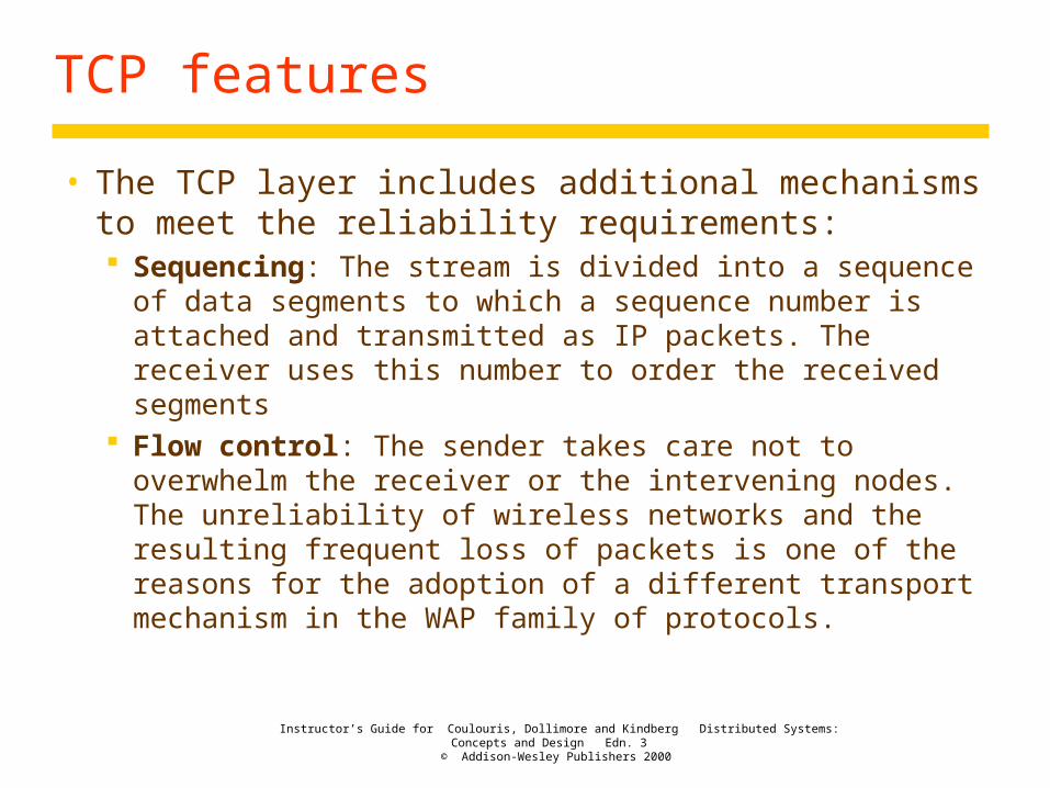
• The TCP layer includes additional mechanisms to meet the reliability requirements: Sequencing: The stream is divided into a sequence
of data segments to which a sequence number is attached and transmitted as IP packets. The receiver uses this number to order the received segments
Flow control: The sender takes care not to overwhelm the receiver or the intervening nodes. The unreliability of wireless networks and the resulting frequent loss of packets is one of the reasons for the adoption of a different transport mechanism in the WAP family of protocols.

Instructor’s Guide for Coulouris, Dollimore and Kindberg Distributed Systems: Concepts and Design Edn. 3
© Addison-Wesley Publishers 2000
TCP features
Retransmission: The sender records the sequence numbers of the segments. When it receives an acknowledgement, it notes that the segments were received and it may then delete them from its outgoing buffers. If any segment is not acknowledged within a specified timeout, the sender retransmits it.
Buffering: The incoming buffer at the receiver is used to balance the flow between the sender and the receiver.
Checksum: Each segment carries a checksum covering the header and the data segment.

Instructor’s Guide for Coulouris, Dollimore and Kindberg Distributed Systems: Concepts and Design Edn. 3
© Addison-Wesley Publishers 2000
Domain names
• The Internet supports a scheme for the use of symbolic names for hosts and networks.
• The named entities are organized into a naming hierarchy. The named entities are called domains and the symbolic names are called domain names.
• The Domain Name System (DNS) is used to translate domain names into IP address.
Instructor’s Guide for Coulouris, Dollimore and Kindberg Distributed Systems: Concepts and Design Edn. 3
© Addison-Wesley Publishers 2000
Domain names
• The DNS servers in each domain hold a partial map of the domain name tree below their domain.
• DNS servers handle requests for the translation of domain names outside their portion of the tree by issuing requests to DNS servers in the relevant domains. The result is then cached for the future request.

Instructor’s Guide for Coulouris, Dollimore and Kindberg Distributed Systems: Concepts and Design Edn. 3
© Addison-Wesley Publishers 2000
Discovering Network Topology
• netstat –ni• netstat –rn• Do a man netstat to look at the command
options.• Try netstat -a• /sbin/ifconfig eth0• /sbin/ifconfig lo• Do a man ifconfig to look at the command
options.• Do /usr/sbin/ping –s 156.26.10.255 on Solaris.

Instructor’s Guide for Coulouris, Dollimore and Kindberg Distributed Systems: Concepts and Design Edn. 3
© Addison-Wesley Publishers 2000
Firewalls
• The purpose of a firewall is to monitor and control all communication into and out of an intranet : Service control: To determine which services on
internal hosts are accessible for external access and the reject all other incoming service requests.
Behavior control: To prevent behavior that infringes the organization’s policies.
User control: The organization may wish to discriminate between its users.
Instructor’s Guide for Coulouris, Dollimore and Kindberg Distributed Systems: Concepts and Design Edn. 3
© Addison-Wesley Publishers 2000
Firewalls
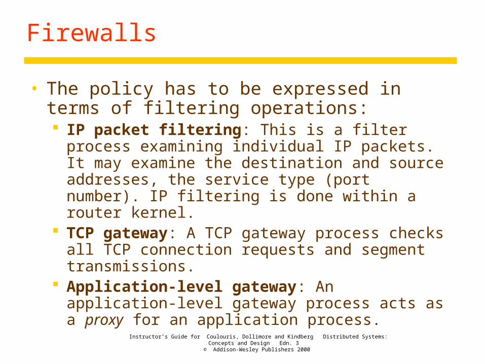
• The policy has to be expressed in terms of filtering operations: IP packet filtering: This is a filter process examining
individual IP packets. It may examine the destination and source addresses, the service type (port number). IP filtering is done within a router kernel.
TCP gateway: A TCP gateway process checks all TCP connection requests and segment transmissions.
Application-level gateway: An application-level gateway process acts as a proxy for an application process.

Instructor’s Guide for Coulouris, Dollimore and Kindberg Distributed Systems: Concepts and Design Edn. 3
© Addison-Wesley Publishers 2000
Firewalls
• The router/filter must run only trusted software in a manner that enables its enforcement of filtering policies to be guaranteed.
• This involves ensuring that no Trajan horse processes can run on it and that software have not been modified or tampered with.
• Figure 3.20(a) shows a simple firewall.• When TCP and application-level gateway
processes are required, these usually run on a separate computer, known as a bastion.

Instructor’s Guide for Coulouris, Dollimore and Kindberg Distributed Systems: Concepts and Design Edn. 3
© Addison-Wesley Publishers 2000
Firewalls
• A bastion computer is a host that is located inside the intranet protected by an IP router/filter and runs the TCP and application-level gateways (Figure 3.20(b)).
• Security can be enhanced by employing two router/filters in series, with the bastion and any public servers located on a separate subnet linking the router/filters (Figure 3.20(c)).

Instructor’s Guide for Coulouris, Dollimore and Kindberg Distributed Systems: Concepts and Design Edn. 3
© Addison-Wesley Publishers 2000
Figure 3.20Firewall configurations
Internet
Router/Protected intraneta) Filtering router
Internet
b) Filtering router and bastion
filter
Internet
R/filterc) Screened subnet for bastion R/filter Bastion
R/filter Bastion
web/ftpserver
web/ftpserver
web/ftpserver

Instructor’s Guide for Coulouris, Dollimore and Kindberg Distributed Systems: Concepts and Design Edn. 3
© Addison-Wesley Publishers 2000
Firewalls
• This configuration (Fig. 3.20 (c)) has several security advantages: If the bastion policy is strict, the IP addresses of hosts
in the intranet need not be published to the outside world and the external addresses need not be known, because all external communication passes through proxy processes in the bastion.
If the first filter is compromised, the second one invisible from outside is less vulnerable.
• Virtual private networks (VPNs) extend the firewall protection boundary beyond the local intranet by use of cryptographically protected secure channels at the IP level.

Instructor’s Guide for Coulouris, Dollimore and Kindberg Distributed Systems: Concepts and Design Edn. 3
© Addison-Wesley Publishers 2000
Network Case Studies
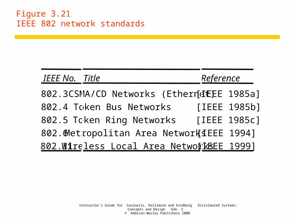
• The IEEE 802 network standards are shown in Figure 3.21.
• The IEEE 802.3 Ethernet standard has largely won the marketplace.
• The IEEE 802.5 Token Ring standard has now disappeared from the marketplace.
• The IEEE 802.4 Token Bus standard was developed for industrial applications with real-time requirements.
• The IEEE 802.6 Metropolitan Area standard covers distances up to 50 km.
Instructor’s Guide for Coulouris, Dollimore and Kindberg Distributed Systems: Concepts and Design Edn. 3
© Addison-Wesley Publishers 2000
Figure 3.21IEEE 802 network standards
IEEE No. Title Reference
802.3 CSMA/CD Networks (Ethernet) [IEEE 1985a]
802.4 Token Bus Networks [IEEE 1985b]
802.5 Token Ring Networks [IEEE 1985c]
802.6 Metropolitan Area Networks [IEEE 1994]
802.11 Wireless Local Area Networks [IEEE 1999]

Instructor’s Guide for Coulouris, Dollimore and Kindberg Distributed Systems: Concepts and Design Edn. 3
© Addison-Wesley Publishers 2000
Network Case Studies
• The IEEE 802.11 Wireless LAN standard now has products from Lucent (WaveLAN).
• The IEEE 802.11 standard is designed to support communication at speed up to 11 Mbps over distances of up to 150 m.
• The purpose of ATM is to provide a high-bandwidth wide-area digital networking technology suitable for telephone, data and multimedia applications.

Instructor’s Guide for Coulouris, Dollimore and Kindberg Distributed Systems: Concepts and Design Edn. 3
© Addison-Wesley Publishers 2000
Ethernet
• History - Xerox PARC in 1973, IEEE/ISO Standard 802.3 in 1985
• An single Ethernet is a bus-like connection. An Ethernet LAN consisting of three computers joined by a shared coaxial cable is shown in the following diagram:

Instructor’s Guide for Coulouris, Dollimore and Kindberg Distributed Systems: Concepts and Design Edn. 3
© Addison-Wesley Publishers 2000
Ethernet
• A Ethernet belongs to the class of contention bus networks. Hubs (repeaters) extend segments of Ethernet. Switches (bridges) operate at the level of Ethernet frame.
• The method of operation is defined by CSMA/CD (Carrier Sensing, Multiple Access with Collision Detection).
• Contention buses use a single transmission medium to link all of the hosts.
Instructor’s Guide for Coulouris, Dollimore and Kindberg Distributed Systems: Concepts and Design Edn. 3
© Addison-Wesley Publishers 2000
Packet Broadcasting
• The method of communication in CSMA/CD networks is by broadcasting packets of data on the transmission medium.
• The packet is broadcasting with the destination address which specifies either a single recipient node (unicast mode), a group of recipient nodes (multicast mod), or the set of all recipient nodes (broadcast mode).

Instructor’s Guide for Coulouris, Dollimore and Kindberg Distributed Systems: Concepts and Design Edn. 3
© Addison-Wesley Publishers 2000
Ethernet Packet Layout
• Frames of data are formed using a protocol called Medium Access Control (MAC). It is used to provide the data link layer of the Ethernet LAN system.
• The MAC protocol encapsulates a payload data by adding a 14 byte header (Protocol Control Information (PCI)) before the data and appending a 4-byte (32-bit) Cyclic Redundancy Check (CRC) after the data.

Instructor’s Guide for Coulouris, Dollimore and Kindberg Distributed Systems: Concepts and Design Edn. 3
© Addison-Wesley Publishers 2000
Ethernet Packet Layout
• The purpose of the preamble is to allow time for the receiver in each node to achieve lock of the receiver Digital Phase Lock Loop which is used to synchronize the receive data clock to the transmit data clock.
• This consists of 62 alternating 1's and 0's followed by the pattern 11.

Instructor’s Guide for Coulouris, Dollimore and Kindberg Distributed Systems: Concepts and Design Edn. 3
© Addison-Wesley Publishers 2000
Ethernet Packet Layout
• The last byte which finished with the '11' is known as the "Start of Frame Delimiter".
• The header consists of three parts: A 6-byte destination address A 6-byte source address A 2-byte data length
• The data field contains the data for transmission.

Instructor’s Guide for Coulouris, Dollimore and Kindberg Distributed Systems: Concepts and Design Edn. 3
© Addison-Wesley Publishers 2000
Ethernet Packet Layout
• The 32-bit CRC added at the end of the frame provides error detection in the case where line errors (or transmission collisions in Ethernet) result in corruption of the MAC frame.
• Any frame with an invalid CRC is discarded by the MAC receiver without further processing.

Instructor’s Guide for Coulouris, Dollimore and Kindberg Distributed Systems: Concepts and Design Edn. 3
© Addison-Wesley Publishers 2000
Packet Collisions
• The Ethernet has three mechanisms to deal with the collisions: Carrier sensing – sense if the line is busy. Collision detection – detect if the collisions occur. Back-off – wait for some time to retransmit.
• T is the time for a signal reaching all other points.

Instructor’s Guide for Coulouris, Dollimore and Kindberg Distributed Systems: Concepts and Design Edn. 3
© Addison-Wesley Publishers 2000
Packet Collisions
send_frame (...){ while (the bus is busy) wait (); send the frame to the bus; if (collision detected in time 2 * T) { wait for some time; resend the frame until no collision detected; }}

Instructor’s Guide for Coulouris, Dollimore and Kindberg Distributed Systems: Concepts and Design Edn. 3
© Addison-Wesley Publishers 2000
Ethernet Efficiency
• The efficiency of an Ethernet is the ratio of the number of packets transmitted successfully as a proportion of the theoretical maximum number that could be transmitted without collisions.
• The Ethernet can achieve a channel utilization of between 80 and 95%. The delays become noticeable when 50% utilization is exceeded.

Instructor’s Guide for Coulouris, Dollimore and Kindberg Distributed Systems: Concepts and Design Edn. 3
© Addison-Wesley Publishers 2000
Physical Implementations
• Ethernet LANs may be implemented using a variety of media.
• The types of media segments supported by Ethernet are: 10B5 Low loss coaxial cable (also known as "thick"
Ethernet) 10B2 Low cost coaxial cable (also known as "thin"
Ethernet) 10BT/100BT/1000BT Low cost twisted pair copper
cable (also known as Unshielded Twisted Pair (UTP)) 10BF Fiber optic cable

Instructor’s Guide for Coulouris, Dollimore and Kindberg Distributed Systems: Concepts and Design Edn. 3
© Addison-Wesley Publishers 2000
Wireless LAN
• The IEEE 802.11 standard extends the carrier-sensing multiple access (CSMA) principle employed by Ethernet (IEEE 802.3).
• The IEEE 802.11 standard is intended to support communication between computers within 150 meter distance at speeds up to 11Mbps.
• Figure 3.22 illustrates portion of an intranet including a wireless LAN.

Instructor’s Guide for Coulouris, Dollimore and Kindberg Distributed Systems: Concepts and Design Edn. 3
© Addison-Wesley Publishers 2000
Figure 3.22Wireless LAN configuration
LAN
Server
WirelessLAN
Laptops
Base station/access point
Palmtop
radio obstruction
A B C
DE

Instructor’s Guide for Coulouris, Dollimore and Kindberg Distributed Systems: Concepts and Design Edn. 3
© Addison-Wesley Publishers 2000
Wireless LAN
• Wireless devices communicate through a base station called an access point.
• An alternative configuration for wireless networking is known as an ad hoc network. They are built on the fly as a result of the mutual detection of two or more wireless devices.
• The stations in IEEE 802.11 networks use radio frequency signals (in the 2.4 GHz band) or infra-red signalling as the transmission medium.

Instructor’s Guide for Coulouris, Dollimore and Kindberg Distributed Systems: Concepts and Design Edn. 3
© Addison-Wesley Publishers 2000
Wireless LAN
• It uses various frequency-selection and frequency-hopping techniques to avoid interfere.
• Frequency-hopping uses a narrowband carrier that changes frequency in a pattern known to both transmitter and receiver. Properly synchronized, the net effect is to maintain a single logical channel.

Instructor’s Guide for Coulouris, Dollimore and Kindberg Distributed Systems: Concepts and Design Edn. 3
© Addison-Wesley Publishers 2000
Wireless LAN
• Because signal strength is not uniform throughout the space in which wireless LANs operate, carrier detection and collision may fail in the following ways: Hidden stations: Carrier sensing may fail to detect
another station. For example, A and D. Fading: The strength of radio signals diminished
rapidly with the distance from the transmitter. For example, A and C.
Collision masking: The local signal might drown out the remote transmission. For example, A and C.
• The result scheme is carrier sensing multiple access with collision avoidance (CSMA/CA).

Instructor’s Guide for Coulouris, Dollimore and Kindberg Distributed Systems: Concepts and Design Edn. 3
© Addison-Wesley Publishers 2000
Wireless LAN
• When a station is ready for transmission, if it detects no carrier signal it may assume: The medium is available. An out-of-range station is in the process of requesting
a slot. An out-of-range station is using a slot that it had
previously reserved.
• The slot-reservation protocol involves the exchange of a request to send (RTS) frame from the sender to the receiver and clear to send (CTS) frame from the receiver.

Instructor’s Guide for Coulouris, Dollimore and Kindberg Distributed Systems: Concepts and Design Edn. 3
© Addison-Wesley Publishers 2000
Wireless LAN
• The effect of this exchange is as follows: Stations within range of the sender will pick the RTS
frame and note the duration. Stations within range of the receiver will pick the CTS
frame and note the duration.
• The slot-reservation feature of the MAC protocol helps to avoid the collisions in these ways: The CTS frames help to avoid the hidden station and
fading problems.

Instructor’s Guide for Coulouris, Dollimore and Kindberg Distributed Systems: Concepts and Design Edn. 3
© Addison-Wesley Publishers 2000
Wireless LAN
If a collision is detected, or an RTS does not result in a CTS, a random back-off period is used.
When the RTS and CTS frames have been correctly exchanged, there should be no collisions.
• The privacy and integrity of communication is an obvious concern for wireless networks.
• It requires an authentication exchange for each station joining the network in which knowledge of a shared key is demonstrated.
• The prevention of eavesdropping is achieved using a simple encryption scheme.

Instructor’s Guide for Coulouris, Dollimore and Kindberg Distributed Systems: Concepts and Design Edn. 3
© Addison-Wesley Publishers 2000
Asynchronous Transfer Mode (ATM)
• ATM has been designed to carry a wide variety of data including multimedia data such as voice and video.
• It is a fast packet-switching network based on cell relay.
• It achieves its speed by avoiding flow control and error checking at the intermediate nodes and using the small and fixed-length units of data transmission.

Instructor’s Guide for Coulouris, Dollimore and Kindberg Distributed Systems: Concepts and Design Edn. 3
© Addison-Wesley Publishers 2000
Asynchronous Transfer Mode (ATM)
• ATM connection is set up only if sufficient resources are available. Once it is set up, the quality is guaranteed.
• ATM is a data-switching technology that can be implemented over existing digital telephony networks and Synchronous Optical Network (SONET).
• The resulting virtual circuits can provide services including voice, fax, HDTV (100-150 Mbps).
• The ATM can transfer data at the rates up to 155 Mbps or 622 Mbps.

Instructor’s Guide for Coulouris, Dollimore and Kindberg Distributed Systems: Concepts and Design Edn. 3
© Addison-Wesley Publishers 2000
Asynchronous Transfer Mode (ATM)
• ATM networks can also be implemented in native mode directly over optical fiber, copper, and other transmission media, allowing bandwidths of up to several gigabits per second.
• The ATM service is structured in three layers as shown in Figure 3.23: Adaptation layer – end-to-end layer implemented at
the sending and receiving hosts. ATM layer – a connection-oriented service that
transmits fixed length packets called cells. Physical layer

Instructor’s Guide for Coulouris, Dollimore and Kindberg Distributed Systems: Concepts and Design Edn. 3
© Addison-Wesley Publishers 2000
Figure 3.23ATM protocol layers
Physical
Application
ATM layer
Higher-layer protocols
ATM cells
ATM virtual channels
MessageLayers
ATM adaption layer

Instructor’s Guide for Coulouris, Dollimore and Kindberg Distributed Systems: Concepts and Design Edn. 3
© Addison-Wesley Publishers 2000
Asynchronous Transfer Mode (ATM)
• A connection consists of sequence of virtual channels within virtual paths. A virtual channel (VC) is a logical unidirectional association between two endpoints.
• A virtual path (VP) is a bundle of virtual channels that are associated with a physical path between two switching nodes.

Instructor’s Guide for Coulouris, Dollimore and Kindberg Distributed Systems: Concepts and Design Edn. 3
© Addison-Wesley Publishers 2000
Asynchronous Transfer Mode (ATM)
• The nodes in an ATM network can play three distinct roles: Hosts, that send and receive messages; VP switches, that hold tables showing the
correspondence between incoming and outgoing virtual paths;
VP/VC switches, that hold similar tables for both virtual paths and virtual channels.
• An ATM cell has a 5-byte header and a 48-byte data field as shown in Figure 3.24.

Instructor’s Guide for Coulouris, Dollimore and Kindberg Distributed Systems: Concepts and Design Edn. 3
© Addison-Wesley Publishers 2000
Figure 3.24ATM cell layout
Flags DataVirtual channel idVirtual path id
53 bytes
Header: 5 bytes
Instructor’s Guide for Coulouris, Dollimore and Kindberg Distributed Systems: Concepts and Design Edn. 3
© Addison-Wesley Publishers 2000
Asynchronous Transfer Mode (ATM)
• When a cell arrives at a VP switch, the virtual path identifier in the header is looked up in its routing table to work out the corresponding virtual path for the outgoing physical path as shown Figure 3.25.
• The VP and VC identifier are defined locally. This scheme doesn’t need global network-wide identifiers.
• ATM provides a service with low latency of 25 microseconds per switch.

Instructor’s Guide for Coulouris, Dollimore and Kindberg Distributed Systems: Concepts and Design Edn. 3
© Addison-Wesley Publishers 2000
Figure 3.25Switching virtual paths in an ATM network
VPI in VPI out
23
45
VPI = 3
VPI = 5
VPI = 4
Virtual path Virtual channels
VPI = 2
VPI : virtual path identifier
VP switch VP/VCswitch
VP switch
Host
Host