Embed Size (px)
Citation preview

CS1-RL-2009-05-26 C1-11-1/7
CS1-RL PULSE (Freq.) Indicator
DESCRIPTION
CS1-RL economic type Pulse Indicator has been designed with high accuracy measurement, display and communication of pulse(Frequency).
The innovation feature is auto-range input from 0.01Hz~ 100KHz(option ~140KHz) and the display resolution will auto-change to show the highest according to input frequency.
They are also available 1 option of 1 Relay outputs, 1 Analogue output or 1 RS485(Modbus RTU Mode) interface with versatile functions such as control, alarm, re-transmission or communication for a wide range of testing and machinery control applications.
FEATURE Measuring Frequency AUTO RANGE 0.01~100KHz / ~140KHz(optional) / Contact, NPN, PNP,
Voltage pulse changeable by dip switch. Accuracy: ± 0.005%; Display range: 0~99999; Decimal Point auto moving according to input
frequency Option available 1 of 1 relay, 1 analogue output or RS485(Modbus RTU mode) 1 relay can be programmed to be a Hi / Lo / Hi Latch / Lo Latch energized with Start Delay /
Hysteresis / Energized & De-energized Delay functions, or to be a remote control. Analogue output or RS 485 communication port in option CE Approved & RoHS
ORDERING INFORMATION CS1−RL− Input
Mode Input Level − Optional
Output − Excitation Supply − Aux. Power
CODE INPUT MODE CODE OPTIONAL OUTPUT CODE EXCIT. SUPPLY CODE AUX. POWER C 00 Contact N None E05 DC 5 V A AC 115/230 V N NPN R1 1 Relay E12 DC 12 V P PNP E24 DC 24 V ADH* AC/DC 85~264V V Voltage pulse V 0(1) ~ 5 V
0 ~ 10 V ADL* AC/DC 20~90V 05 5V pulse 12 12V pulse I 0 ~ 10 mA
0(4)~20 mA
The excitation supply has to match the input mode. The standard is DC12V for 12Vp
24 24V pulse 8 RS485 O xx Specify
Relay, Analogue Output or RS485 Port can be selected one only.
Display range: 0.0000~99999 with auto moving of decimal point
TECHNICAL SPECIFICATION Resolution of PV: Input (Auto-Moving for d.p.) Auto / Semi-Auto / Fix; 3 mode programmable Input Frequency Input Mode Input Level Compensation factor: Compensate error from 0.001~9.999 0.01Hz ~ 50 Hz Mech. Contact Over range indication: ovFL, when input is over 120% of input range Hi
NPN Max / Mini recording: Maxi & Mini Value of PV storage during power on. PNP
High Level: 8~12V; Low Level: 0.0~4.0 V (with excitation supply 12Vdc) Display functions: PV / Max(Mini) Hold / RS 485 programmable
Front key functions: Relative PV / PV Hold / Reset for maxi(mini) hold /
0.01Hz ~ 50 Hz 0.01Hz ~ 100KHz 0.01Hz ~ 140KHz (optional) Voltage Pulse High Level: over 2/3 of input level
Low Level: under 1/3 of input level Reset for relay energized latch programmable Low cut: Settable range: -19999~29999 counts Input Mode(NPN, PNP, Contact) & Level(5Vp, 12Vp, 24Vp)
changeable by dip switch of rear terminal block. Digital fine adjust: Pv.Zro: Settable range: 0~+99999 Pv.SPn: Settable range: 0~+99999 Calibration: Doesn’t need calibration Input range: Auto range: 0.01Hz ~ 100KHz (~140KHz in option); Reading Stable Function Accuracy: ≤± 0.005% of FS± 1C; Average: Settable range: 1~99 times Sampling time: 15 cycles/sec(≥15Hz); Moving average: Settable range: 1(None)~10 times f cycles/sec(≤15Hz) Digital filter: Settable range: 0(None)/1~99 times Response time: ≤100 msec(when the AvG = “1”) Time out function: Auto, Manual programmable, In manual mode, the period Control Functions(option) of time out can be set 0.0 sec~999.9sec Set-points: One set-points Control relay: One relays, FORM-C, 5A/230Vac, 10A/115V Display & Functions Relay energized mode: Energized levels compare with set-points: LED: Numeric: 5 digits, 0.8”(20.0mm)H red high-brightness Hi / Lo / Hi.HLd / Lo.HLd programmable Relay output indication: 1 square red LED Energizing functions: Start delay / Energized & De-energized delay / Hysteresis RS 485 communication: 1 square red LED Energized Latch E.C.I. function indication: 1 square green LED Start band(Minimum level for Energizing): 0~9999counts Max/Mini Hold indication: 2 square orange LED Start delay time: 0:00.0~9(Minutes):59.9(Second) Down key function indication(Reset for Max.(Mini.) Hold / Energized delay time: 0.00.0~9(Minutes):59.9(Second) PV Hold / Rel. PV ): 1 square green LED De-energized delay time: 0.00.0~9(Minutes):59.9(Second)Display type: RPM / RPS / Linear Line Speed / Frequency Hysteresis: 0~5000 counts
CS
M-3
21S
CS2-VA
CS
M-3
21S
C
SM
-C
SM
-C
S1-R
L C
SM
-321
S
CS
M-
CS
M-
CS
M-3
21S
C
SM
-C
SM
-321
S
Input mode and level can be changed by dip switches on rear of meter
OPTION
OPTION 4

CS1-RL-2009-05-26 C1-11-2/7
Analogue output(option) Accuracy: ≤± 0.1% of F.S.;
DIMENSIONS Ripple: ≤± 0.1% of F.S. Response time: ≤100 msec. (10~90% of input) Isolation: AC 2.0 KV between input and output Output range: Specify either Voltage or Current output in ordering Voltage: 0~5V / 0~10V / 1~5V programmable Current: 0~10mA / 0~20mA / 4~20mA programmable Output capability: Voltage: 0~10V: ≥ 1000Ω; Current: 4(0)~20mA: ≤ 600Ω max Functions: Ao.HS(output range high): Settable range: -19999~99999 Ao.LS(output range Low): Settable range: -19999~99999Digital fine adjust: Ao.Zro: Settable range: -38011~+27524 Ao.SPn: Settable range: -38011~+27524
96.0
48.0
92.0+0.2
44.0+0.2 PANEL CUT-OUT
FRONT VIEW
Unit: mm
8.0
12.060.0
Dimensions: 96mm x 48mm x 72mmPanel Cutout: 93mm x 45mm (advise)
RS 485 Communication(option)
INSTALLATION Protocol: Modbus RTU mode Baud rate: 1200/2400/4800/9600/19200/38400 programmable
The meter should be installed in a location that dose not exceed the maximum operating temperature and provides good air circulation.
Data bits: 8 bits Parity: Even, odd or none (with 1 or 2 stop bit) programmable Address: 1 ~ 255 programmable Remote display: to show the value from RS485 command of master Distance: 1200M Terminate resistor: 150Ω at last unit. Electrical Safety Dielectric strength: AC 2.0 KV for 1 min, Between Power / Input / Output / Case
1.0~8.0 mm
FIX HOLDER:63 mm(L) / W M3PANEL CUT-OUT:
92+0.2(W) x 44+0.2(H) mm
R L COMCI1
ENT/FN ? ? ? M/min
Insulation resistance: ≥100M ohm at 500Vdc, Between Power / Input / Output Isolation: Between Power / Input / Relay, Analogue, RS485
CONNECTION DIAGRAM EMC: EN 55011:2002; EN 61326:2003 Safety(LVD): EN 61010-1:2001 Environmental Operating temp.: 0~60 ˚C Operating humidity: 20~95 %RH, Non-condensing Temp. coefficient: ≤100 PPM/˚C Storage temp.: -10~70 ˚C Enclosure: Front panel: IEC 549 (IP54); Housing: IP20 Mechanical
D-S 1 2 3 4 5NPN ON PNP ON M.C. ON ON5VP 12VP ON 24VP ON D-S is on, when it is on down side.
Relay
b c a
Relay, Analogue o/p or RS485 port can be selected one only.
Terminal blocks:10A/300Vac, M2.6, 1.3~2.0mm2 (16~12AWG)
Analogue output
RS 485 port A B
FG
7 8 9 10D-SDip-Switch 5 6 4 11 12 14 1513 16
ADLADH AC/DC 86~265V
AC/DC 20~90V
AC230V
AUX. POWER
AC115V
0V
+ Vdc
+IN
SIGNAL INPUTFreqency/Pulse
Dimensions: 96mm(W) x 48mm(H) x 72mm(D) Panel cutout: 92mm(W) x 44mm(H) Case materiel: ABS fire-resistance (UL 94V-0)
Please check the voltage of power supplied first, and then connect to the specified terminals. It is recommended that power supplied to the meter be protected by a fuse or circuit breaker.
Mounting: Panel flush mounting Terminal block: Plastic NYLON 66 (UL 94V-0) 10A 300Vac, M2.6, 1.3~2.0mm2(16~12AWG) Weight: 350g / 300g(Aux. Power Code: ADH or ADL) Power Power supply: AC115/230V,50/60Hz; Optional: AC/DC 85~264V or 20~90V(RoHS version)
Power Supply
AC115/230V AC85~264V
Filter or Transformer
L
N
G
L
N
G
1A Fuse 6 7 9 108
Excitation supply: DC12V, 24V/30mA maximum Power consumption: 4.5VA maximum Back up memory: By EEPROM
FRONT PANEL
Sensor input connection
D-S 1 2 3 4 5NPN ON PNP ON M.C. ON ON5VP 12VP ON 24VP ON D-S is on when it is in down site
11 12 14 1513
+Vdc Out0V
+IN
0V
+V
+Vdc Out0V
Please change the dip-switch on rear of meter to match the input mode and level.
R L 1 COM
CI11
ENT/FN ? ? ? M/mi
M.H
M.H
Comm. statusRelay status
Indication
Operation Key
Front Key function status
Engineer Unit
Display screen
Max. Hold status
Mini. Hold status
RS485 Communication Port RS485 Port
4 5 6
A B
Max. Distance: 1200M Terminate Resistor (at latest unit): 120~300ohm/0.25W (typical: 150ohm)
CS
M-3
21S
CS2-VA
CS
M-3
21S
C
SM
-C
SM
-
CS1-R
L
CS
M-3
21S
C
SM
-C
SM
-C
SM
-321
S
CS
M-
CS
M-3
21S
CS1-RL-2009-05-26 C1-11-3/7
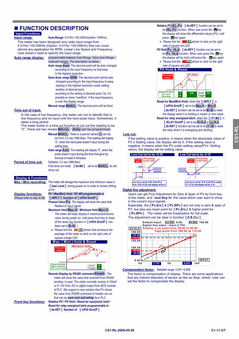
Relative PV rEL.Pv :【dn.KEY】function can be set to
FUNCTION DESCRIPTION be rEL.Pv function. When user press the
key, Input Functions the display will show the differential value(∆PV), untilInput range: Auto-Range: 0.01Hz~100.00KHz(option 140KHz), press
key again.
Please find the R.PV sticker to stick on the right side of square red LED. PV Hold Pv. HLd :【dn.KEY】function can be set to
The meter has been designed very wide input range from 0.01Hz~100.00KHz (Option: 0.01Hz~140.00KHz) that can cover almost any application for RPM, Linear Line Speed and Frequency. User doesn’t need to specify the input range. be Pv. HLd function. When user press the
key,Auto range display: programmable between Auto Range / Semi-Auto Range / the display will be hold until press the
key again. manual range, The description as below, Please find the PV.H sticker to stick on the right Auto range Auto: The decimal point will be auto changed side of square red LED.
according to the input frequency so that keep in the highest resolution.
Semi-Auto range SEMi: The decimal point will be auto changed according to the input frequency to keep reading in the highest resolution under setting
position of decimal point. according to the setting of decimal point. So, it’s
possible to show “overflow”, if the input frequency
PV Hold & Reset
Present Value
Reset PV Hold by Front
DownKey ON
EdgeTrigger
ON ON
PV Hold
is over the display range. Reset for Max(Mini) Hold: when the【dSPLY】in Manual range MANUL: The decimal point will be fixed 【inPUt GroUP】set to be Max.H or Mini.H ,
Time out of input: 【dn.KEY】function can be set to be M.rSt to reset the display when it is holding in maxim or mini value.
Reset for relay energized latch: when the【rY1.Md】in 【rELAY GroUP】set to be Hi.HLd or Lo.HLd , 【dn.KEY】function can be set to be rY.rSt to reset
In the case of low frequency, the meter can not to identify that is low frequency and no input until the next pulse input. Sometimes, it takes a long period. The meter builds in a time out function to cut out the reading to be “0”. There are two modes MAnUL / AUto can be programmed. the relay when it is energizing and latching.
Manual MANUL: There is a period named ito can be Low cut: set from 0.0 sec~999.9sec. The reading will display
“0”, when the next pulse doesn’t input during the setting time.
Auto range Auto: The reading will display “0”, when the
If the setting value is positive, it means when the absolutely value of PV ≤ Setting value, the display will be 0. If the setting value is negative, it means when the PV under setting value(PV≤ -Setting value), the display will be setting value.
pulse doesn’t input during the time that gave by formula of meter’s firmware.
Period of time out: Settable: 0.0 sec~999.9sec If the time out mode 【ito.Md】 set to be MANUL, ito will show out. Display & Functions Max / Mini recording: The meter will storage the maximum and minimum value in 【User Level】during power on in order to review drifting
Low Cut set to be +0.50 Low Cut set to be -0.10
-0.10
Low cut function
Low Cut is set for 0.50, if the PV is from -0.50~+0.50, that display will be 0.
Low Cut is set for -0.10, if the PV is under (< = -0.10), that display will be -0.10.
PV according to input signalPresent
Value
Low cut function
0.50
-0.50
Present Value
PV according to input signal
of PV. Digital fine adjustment: Display functions: PV / Max(Mini) Hold / RS 485 programmable in (Please refer to step A-08) 【dSPLY】function of【inPUt GroUP】 Present Value Pv: The display will show the value that Relative to Input signal. Maximum Hold Max.H / Minimum Hold Mini.H : The meter will keep display in maximum(minimum) value during power on, until press front key to reset
Users can get Fine Adjustment for Zero & Span of PV by front key of the meter, and “Just Key In” the value which user want to show in the current input signals. Especially, the【Pv.Zro】&【Pv.SPn】are not only in zero & span of PV, but also any lower point for【Pv.Zro】& higher point for【Pv.SPn】. The meter will be linearization for full scale. The adjustment can be clear in function【Z.S.CLr】.
(If the down key function in【inPUt GroUP】has been set to M.rSt .) Please find the M.H sticker that enclosure the
package of the meter to stick on the right side of square orange LED
D efault Input: Lo.SC : 0.00, H i.SC : 199.99D igital fine adjut.: input 2.75V, D isplay: Low point from 55.00 to 80.00 H igh point from 180.00 tp 170.00
SC ALE
INPU T0.00
199.99
0V 10V5V
100.00
2.75V
55.00
150.00
80.00
9.00V
180.00170.00
Max. ( Mini.) Hold & Reset
Reset the Max (Mini) Hold by E.C.I. or F. Key
ON
Level Trigger
Maximum Hold Present
Value
Compensation factor: Settable range: 0.001~9.999 Remote Display by RS485 command RS485 : The
meter will show the value that received from RS485 sending. In past, The meter normally receive 4~20mA
The factor is compensation of display. There are some applications that are indirect detection of sensor as like as Gear, wheel. User can set the factor to compensate the display.
or 0~10V from AO or digital output from BCD module of PLC .We support a new solution that PV shows the value from RS485 command of master can so that can be save cost and wiring from PLC. Front key functions: Relative PV / PV Hold / Reset for maxi(mini) hold / Reset for relay energized latch programmable in
【dn.KEY】function of 【inPUt GroUP】
CS
M-3
21S
CS2-VA
CS
M-3
21S
C
SM
-C
SM
-C
S1-R
L C
SM
-321
S
CS
M-
CS
M-
CS
M-3
21S
C
SM
-C
SM
-321
S
CS1-RL-2009-05-26 C1-11-4/7
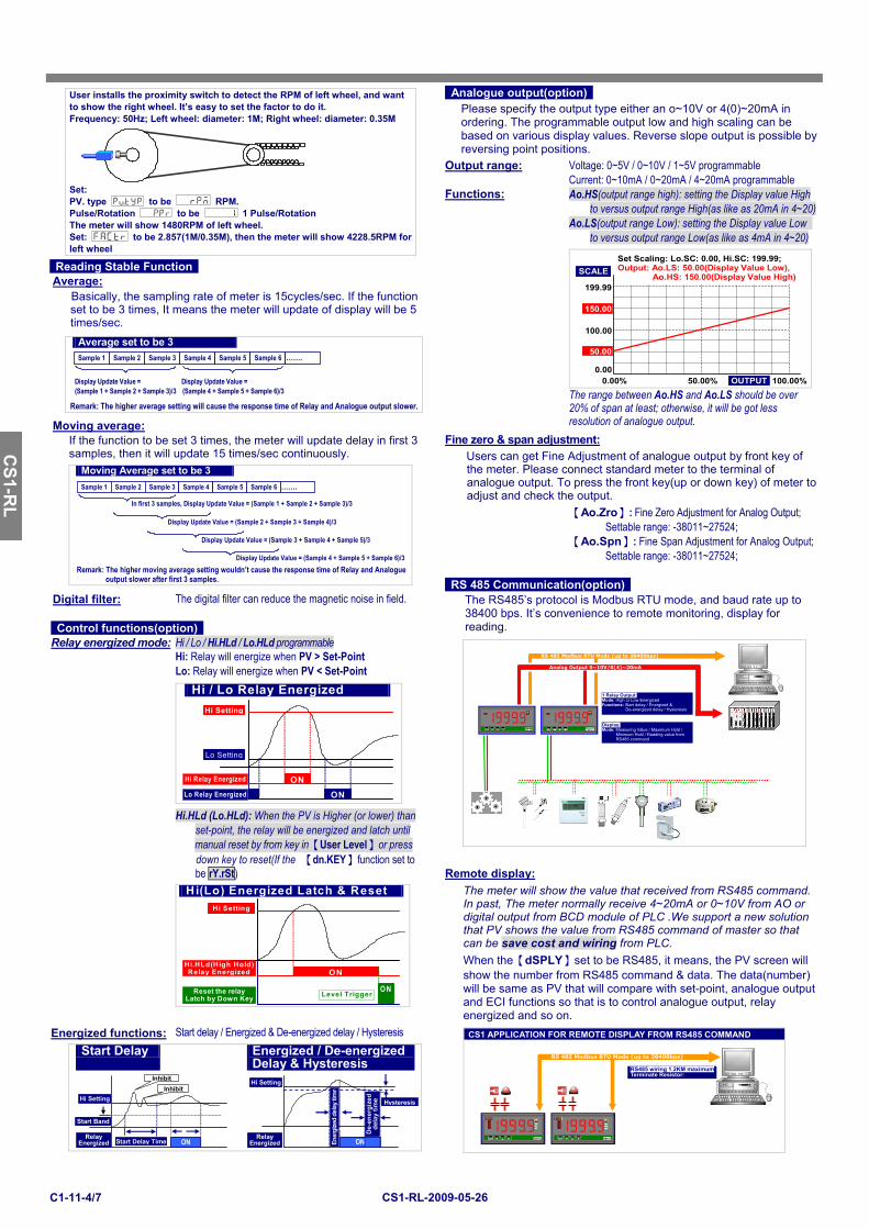
Analogue output(option) Please specify the output type either an o~10V or 4(0)~20mA in ordering. The programmable output low and high scaling can be based on various display values. Reverse slope output is possible by reversing point positions.
Output range: Voltage: 0~5V / 0~10V / 1~5V programmable Current: 0~10mA / 0~20mA / 4~20mA programmable Functions: Ao.HS(output range high): setting the Display value High to versus output range High(as like as 20mA in 4~20) Ao.LS(output range Low): setting the Display value Low to versus output range Low(as like as 4mA in 4~20)
User installs the proximity switch to detect the RPM of left wheel, and want to show the right wheel. It’s easy to set the factor to do it. Frequency: 50Hz; Left wheel: diameter: 1M; Right wheel: diameter: 0.35M Set: PV. type to be RPM. Pulse/Rotation to be 1 Pulse/Rotation The meter will show 1480RPM of left wheel. Set: to be 2.857(1M/0.35M), then the meter will show 4228.5RPM for left wheel
Reading Stable Function Average:
Basically, the sampling rate of meter is 15cycles/sec. If the function set to be 3 times, It means the meter will update of display will be 5 times/sec.
Average set to be 3
Remark: The higher average setting will cause the response time of Relay and Analogue output slower.
Sample 1 Sample 2 Sample 3 Sample 4 Sample 5 Sample 6 …….
Display Update Value = (Sample 1 + Sample 2 + Sample 3)/3
Display Update Value = (Sample 4 + Sample 5 + Sample 6)/3
Moving average:
Set Scaling: Lo.SC: 0.00, Hi.SC: 199.99; Output: Ao.LS: 50.00(Display Value Low),
Ao.HS: 150.00(Display Value High)
0.00% 100.00%50.00% OUTPUT
199.99
100.00
0.00
50.00
150.00
SCALE
The range between Ao.HS and Ao.LS should be over 20% of span at least; otherwise, it will be got less resolution of analogue output.
Fine zero & span adjustment: If the function to be set 3 times, the meter will update delay in first 3 samples, then it will update 15 times/sec continuously. Users can get Fine Adjustment of analogue output by front key of
the meter. Please connect standard meter to the terminal of analogue output. To press the front key(up or down key) of meter to adjust and check the output.
【Ao.Zro】: Fine Zero Adjustment for Analog Output; Settable range: -38011~27524;
【Ao.Spn】: Fine Span Adjustment for Analog Output; Settable range: -38011~27524;
Moving Average set to be 3
Remark: The higher moving average setting wouldn’t cause the response time of Relay and Analogue output slower after first 3 samples.
Sample 1 Sample 2 Sample 3 Sample 4 Sample 5 Sample 6 …….
In first 3 samples, Display Update Value = (Sample 1 + Sample 2 + Sample 3)/3
Display Update Value = (Sample 2 + Sample 3 + Sample 4)/3
Display Update Value = (Sample 3 + Sample 4 + Sample 5)/3
Display Update Value = (Sample 4 + Sample 5 + Sample 6)/3
RS 485 Communication(option) Digital filter: The digital filter can reduce the magnetic noise in field.
Control functions(option)
The RS485’s protocol is Modbus RTU mode, and baud rate up to 38400 bps. It’s convenience to remote monitoring, display for reading.
Relay energized mode: Hi / Lo / Hi.HLd / Lo.HLd programmable Hi: Relay will energize when PV > Set-Point Lo: Relay will energize when PV < Set-Point
Hi / Lo Relay Energized
Hi Setting
Hi Relay Energized ON
Lo Setting
Lo Relay Energized ON Hi.HLd (Lo.HLd): When the PV is Higher (or lower) than set-point, the relay will be energized and latch until manual reset by from key in【User Level】or press
RS 485 Modbus RTU Mode (up to 38400bps)
1 Relay Output: Mode: High or Low Energized Functions: Start delay / Energized &
De-energized delay / Hysteresis
Analog Output 0~10V/0(4)~20mA
Display: Mode: Measuring Value / Maximum Hold /
Minimum Hold / Reading value from RS485 command
R L 1COM
ENT/FN RPM
R L 1COM
EN Kg/cm
down key to reset(If the 【dn.KEY】function set to be rY.rSt) Remote display:
The meter will show the value that received from RS485 command. In past, The meter normally receive 4~20mA or 0~10V from AO or digital output from BCD module of PLC .We support a new solution that PV shows the value from RS485 command of master so that can be save cost and wiring from PLC.
Hi(Lo) Energized Latch & Reset
Hi.HLd(High Hold) Relay Energized ON
Reset the relay Latch by Down Key
O NLevel Trigger
Hi Setting
When the【dSPLY】set to be RS485, it means, the PV screen will show the number from RS485 command & data. The data(number) will be same as PV that will compare with set-point, analogue output and ECI functions so that is to control analogue output, relay energized and so on.
Energized functions: Start delay / Energized & De-energized delay / Hysteresis Start Delay Energized / De-energized
Delay & Hysteresis
Start Delay Time
Start Band
Hi Setting
Relay Energized ON
Inhibit Inhibit
Ener
gize
d de
lay t
ime
ON
Hysteresis
De-
ener
gize
d de
lay
time
Hi Setting
Relay Energized
CS1 APPLICATION FOR REMOTE DISPLAY FROM RS485 COMMAND
RS 485 Modbus RTU Mode (up to 38400bps)
RS485 wiring 1.2KM maximum Terminate Resistor:
R L 1R L 2RL 3RL 4
COM
ECI1ECI2ECI3
ENT/FN Kg/cm2
R L 1R L 2RL 3RL 4
COM
ECI1ECI2ECI3
ENT/FN Kg/cm2
CS
M-3
21S
CS2-VA
CS
M-3
21S
C
SM
-C
SM
-
CS1-R
L
CS
M-3
21S
C
SM
-C
SM
-
CS
M-
CS
M-3
21S
CS1-RL-2009-05-26 C1-11-5/7
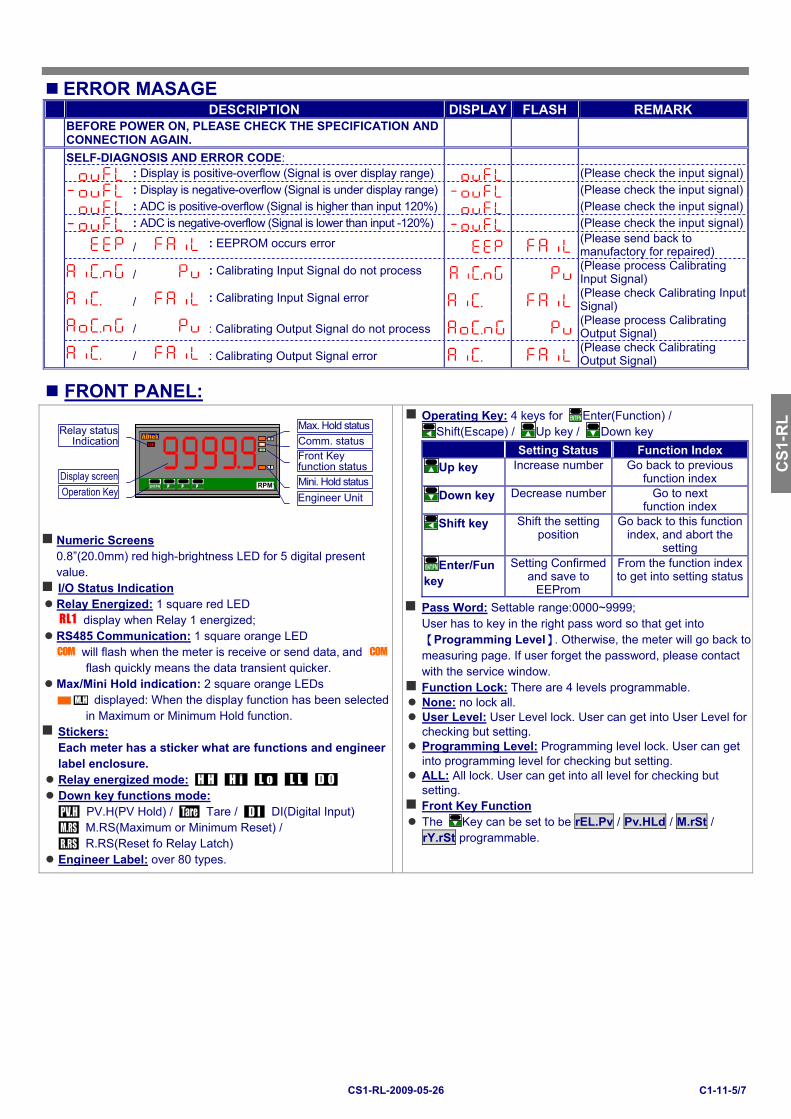
ERROR MASAGE DESCRIPTION DISPLAY FLASH REMARK
BEFORE POWER ON, PLEASE CHECK THE SPECIFICATION AND CONNECTION AGAIN.
SELF-DIAGNOSIS AND ERROR CODE: : Display is positive-overflow (Signal is over display range) (Please check the input signal) : Display is negative-overflow (Signal is under display range) (Please check the input signal) : ADC is positive-overflow (Signal is higher than input 120%) (Please check the input signal) : ADC is negative-overflow (Signal is lower than input -120%) (Please check the input signal)
/ : EEPROM occurs error (Please send back to manufactory for repaired)
/ : Calibrating Input Signal do not process (Please process Calibrating Input Signal)
/ : Calibrating Input Signal error (Please check Calibrating Input Signal)
/ : Calibrating Output Signal do not process (Please process Calibrating Output Signal)
/ : Calibrating Output Signal error (Please check Calibrating Output Signal)
FRONT PANEL:
R L 1 COM
CI11
ENT/FN ? ? ? RPM
M.H
M.H
Comm. statusRelay status
Indication
Operation Key
Front Key function status
Engineer Unit
Display screen
Max. Hold status
Mini. Hold status
Numeric Screens 0.8”(20.0mm) red high-brightness LED for 5 digital present value. I/O Status Indication Relay Energized: 1 square red LED
RL1 display when Relay 1 energized; RS485 Communication: 1 square orange LED
COM will flash when the meter is receive or send data, and COM
flash quickly means the data transient quicker. Max/Mini Hold indication: 2 square orange LEDs
CO M.H displayed: When the display function has been selected in Maximum or Minimum Hold function.
Stickers: Each meter has a sticker what are functions and engineer label enclosure.
Relay energized mode: H H H i
L o L L
D O Down key functions mode:
PV.H(PV Hold) / Tare / DI(Digital Input) M.RS(Maximum or Minimum Reset) / R.RS(Reset fo Relay Latch)
Engineer Label: over 80 types.
Operating Key: 4 keys for
Enter(Function) /
Shift(Escape) /
Up key /
Down key
Setting Status Function Index
Up key Increase number Go back to previous function index
Down key Decrease number Go to next function index
Shift key Shift the setting position
Go back to this function index, and abort the
setting
Enter/Fun key
Setting Confirmed and save to
EEProm
From the function index to get into setting status
Pass Word: Settable range:0000~9999; User has to key in the right pass word so that get into【Programming Level】. Otherwise, the meter will go back to measuring page. If user forget the password, please contact with the service window.
Function Lock: There are 4 levels programmable. None: no lock all. User Level: User Level lock. User can get into User Level for checking but setting.
Programming Level: Programming level lock. User can get into programming level for checking but setting.
ALL: All lock. User can get into all level for checking but setting.
Front Key Function The
Key can be set to be rEL.Pv / Pv.HLd / M.rSt / rY.rSt programmable.
CS
M-3
21S
CS2-VA
CS
M-3
21S
C
SM
-C
SM
-C
S1-R
L C
SM
-321
S
CS
M-
CS
M-
CS
M-3
21S
C
SM
-C
SM
-321
S
CS1-RL-2009-05-26 C1-11-6/7
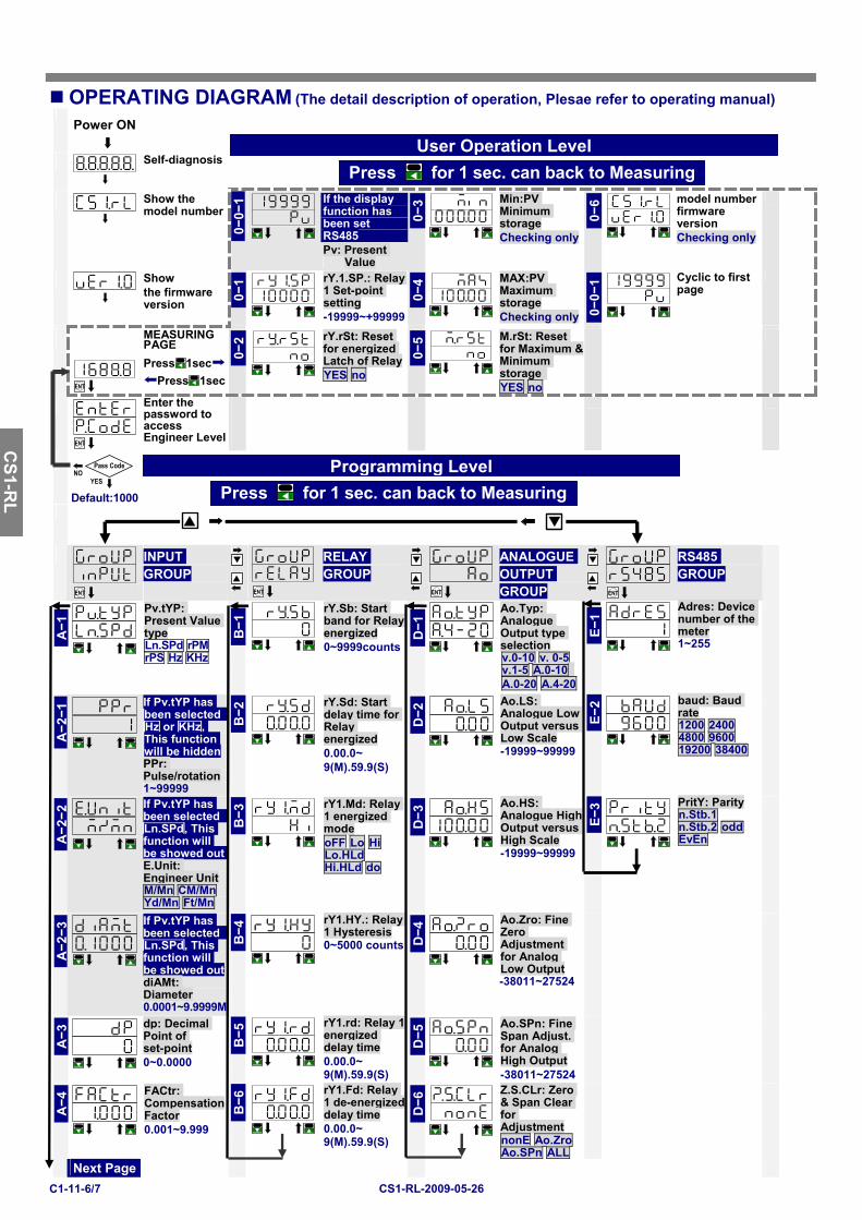
OPERATING DIAGRAM (The detail description of operation, Plesae refer to operating manual)
Power ON
Self-diagnosis
Show the model number
0−0−1
If the display function has been set RS485 Pv: Present
Value
0−3
Min:PV Minimum storage Checking only
0−6
model number firmware version Checking only
Show the firmware version 0
−1
rY.1.SP.: Relay 1 Set-point setting -19999~+99999
0−4
MAX:PV Maximum storage Checking only 0
−0−1
Cyclic to first page
ENT
MEASURING PAGE Press
1sec
Press
1sec
0−2
rY.rSt: Reset for energized Latch of RelayYES no
0−5
M.rSt: Reset for Maximum & Minimum storage YES no
ENT
Enter the password to access Engineer Level
YES
Pass Code NO
Default:1000
ENT
INPUT GROUP
ENT
RELAY GROUP
ENT
ANALOGUE OUTPUT GROUP
ENT
RS485 GROUP
A−1
Pv.tYP: Present Value type Ln.SPd rPM rPS Hz KHz
B−1
rY.Sb: Start band for Relay energized 0~9999counts D
−1
Ao.Typ: Analogue Output type selection v.0-10 v. 0-5 v.1-5 A.0-10 A.0-20 A.4-20
E−1
Adres: Device number of the meter 1~255
A−2−1
If Pv.tYP has been selected Hz or KHz, This function will be hidden PPr: Pulse/rotation 1~99999
B−2
rY.Sd: Start delay time for Relay energized 0.00.0~ 9(M).59.9(S)
D−2
Ao.LS: Analogue Low Output versus Low Scale -19999~99999
E−2
baud: Baud rate 1200 2400 4800 9600 19200 38400
A−2−2
If Pv.tYP has been selected Ln.SPd, This function will be showed out E.Unit: Engineer Unit M/Mn CM/Mn Yd/Mn Ft/Mn
B−3
rY1.Md: Relay 1 energized mode oFF Lo Hi Lo.HLd Hi.HLd do
D−3
Ao.HS: Analogue High Output versus High Scale -19999~99999
E−3
PritY: Parity n.Stb.1 n.Stb.2 odd EvEn
A−2−3
If Pv.tYP has been selected Ln.SPd, This function will be showed out diAMt: Diameter 0.0001~9.9999M
B−4
rY1.HY.: Relay 1 Hysteresis 0~5000 counts D
−4
Ao.Zro: Fine Zero Adjustment for Analog Low Output -38011~27524
A−3
dp: Decimal Point of set-point 0~0.0000
B−5
rY1.rd: Relay 1 energized delay time 0.00.0~ 9(M).59.9(S)
D−5
Ao.SPn: Fine Span Adjust. for Analog High Output -38011~27524
A−4
FACtr: CompensationFactor 0.001~9.999
B−6
rY1.Fd: Relay 1 de-energized delay time 0.00.0~ 9(M).59.9(S)
D−6
Z.S.CLr: Zero & Span Clear for Adjustment nonE Ao.Zro Ao.SPn ALL
Next Page
User Operation LevelPress
for 1 sec. can back to Measuring
Programming LevelPress
for 1 sec. can back to Measuring
CS
M-3
21S
CS2-VA
CS
M-3
21S
C
SM
-C
SM
-
CS1-R
L
CS
M-3
21S
C
SM
-C
SM
-C
SM
-321
S
CS
M-
CS
M-3
21S
CS1-RL-2009-05-26 C1-11-7/7
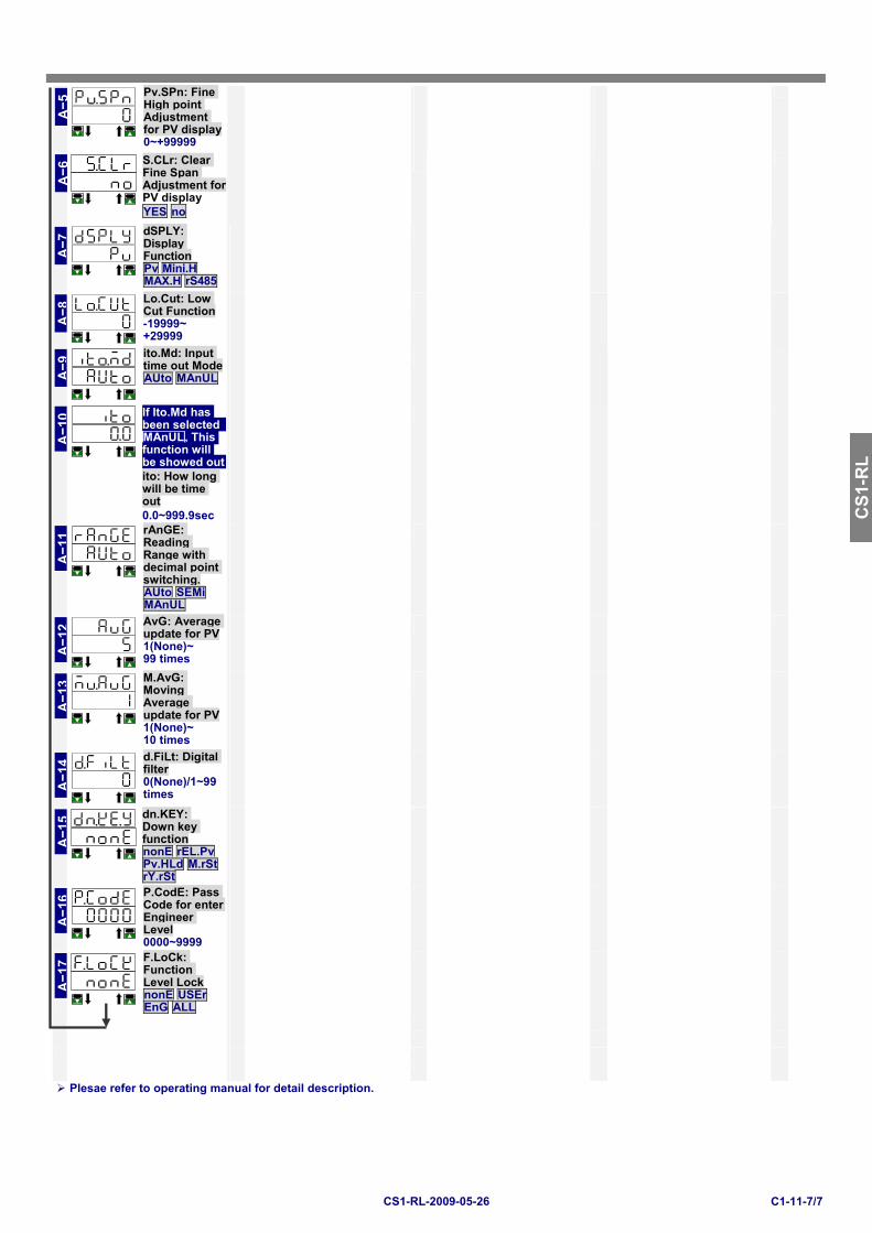
A−5
Pv.SPn: Fine High point Adjustment for PV display 0~+99999
A−6
S.CLr: Clear Fine Span Adjustment for PV display YES no
A−7
dSPLY: Display Function Pv Mini.H MAX.H rS485
A−8
Lo.Cut: Low Cut Function -19999~ +29999
A−9
ito.Md: Input time out Mode AUto MAnUL
A−1
0
If Ito.Md has been selected MAnUL, This function will be showed out ito: How long will be time out 0.0~999.9sec
A−1
1
rAnGE: Reading Range with decimal point switching. AUto SEMi MAnUL
A−1
2
AvG: Average update for PV 1(None)~ 99 times
A−1
3
M.AvG: Moving Average update for PV 1(None)~ 10 times
A−1
4
d.FiLt: Digital filter 0(None)/1~99 times
A−1
5
dn.KEY: Down key function nonE rEL.Pv Pv.HLd M.rSt rY.rSt
A−1
6
P.CodE: Pass Code for enter Engineer Level 0000~9999
A−1
7
F.LoCk: Function Level Lock nonE USEr EnG ALL
Plesae refer to operating manual for detail description.
CS
M-3
21S
CS2-VA
CS
M-3
21S
C
SM
-C
SM
-C
S1-R
L C
SM
-321
S
CS
M-
CS
M-
CS
M-3
21S
C
SM
-C
SM
-321
S