Embed Size (px)
Citation preview

Motion Control Units
CS1 SeriesCS1W-MC421/221
Specification Sheets

1
“Programmable Controller” is abbreviated as “PC” in these Specification Sheets.
CS1-series
Motion Control UnitsCS1W-MC421/221
CS1 Special I/O Unit
Multitasking G Language for Advanced, High-speed, and High-precision 2/4-axisMotion Control
The CS1W-MC421 and CS1W-MC221 areCS1-series Motion Control Units that control fouraxes and two axes, respectively. With their built-inG-language programming capability, they can beused for advanced motion control operations, suchas traversing, and their multitasking capabilityallows operations to be performed independentlyfor each axis. Two types of motion control arepossible: Point-to-point and continuous path.1. Point-to-point Control: With point-to-point (PTP) control,
positioning is controlled independently for each axis. Thepathway varies according to the travel distances, the feedrates, and other set parameters.
2. Continuous Path Control: With continuous path (CP)control, not only the start position and target position can becontrolled but also the path between those points. Linearinterpolation, circular interpolation, helical circular interpola-tion, and traversing are all possible.
The MC Unit has been developed for use in simple position-ing applications using servomotors. Applicable machines areas follows:
• Conveyor Systems: X/Y tables, palletizers/depalletizers,loaders/unloaders, etc.
• Assembling Systems: Automated assembling machines(such as coil winding, polishing, hole punching), simplerobots, etc.
Note: The MC Unit is not designed to perform linear interpolation,circular interpolation, or helical circular interpolation withhorizontal articulated robots or cylindrical robots, becauseit does not support coordinate conversions. The MC Unitcan, however, perform PTP control with these robots.
CS1W-MC421 CS1W-MC221
System Configuration
MC SupportSoftware
Analog inputservodriver
MC Unit(Example: CS1W-MC221)CPU Unit
Servomotor
MC Terminal BlockConversion Unit
Teaching Box
Automatic ModeG language program
Operatingcommands
Data bits
CPU UnitMC Unit
Manual Mode
Manualcontrols
Data bits
Manual controls
CPU UnitMC UnitTeaching Box
Product Specifications

Motion Control Units Product Specifications
2
MC Unit functions
Automatic Mode(Executes G-language programsin the MC Unit.)
Manual Mode(Executes manual commandsfrom the CPU Unit or TeachingBox.)
Common to Automaticand Manual Modes
Position control
Speed control
Origin searchInterrupt feeding
Traversing
Arithmetic operations, etc.
Deceleration stop
Origin search (manual)
Standard origin return
Jogging
Error counter resetForced origin
Absolute origin setting
Servo lock/Servo unlock
TeachingZones
Backlash correction
Override
Present position preset
Electronic gear
Dwell timer
Stop Mode
Pass Mode
In-position Check OFF Mode
FeaturesMultitasking G LanguageThe MC Unit is provided with a multitasking G language, which is theoptimum language for motion control. The G language makes it sim-ple to create programs for multiaxis control, without placing a bur-den on the CPU Unit’s ladder diagram program.
Simple and Fast T raverse OperationsCommands for 2-axis traverse operations enable simple and fasttraverse operations.
Fast Pick-and-place OperationsAfter a positioning command has been output, the in-position checkOFF function allows the next positioning operation to be startedwithout waiting for the first positioning operation to be completed.This makes it possible to perform high-speed pick-and-place opera-tions.
Supports Absolute EncodersThe MC Unit is compatible with absolute encoders as a standardfeature, eliminating the need to perform an origin search. Incremen-tal encoders can be used as well.
High-speed Response to Start Commands from CPU UnitThe response time from when a start command is received from theCPU Unit until the command voltage is output from the MC Unit is 8ms for two axes and 13 ms for four axes (MC421 only). This is 1.5times faster than the previous models.
Note: Two-axis MC UnitThis function applies to the X axis when a 2-axis, 1-taskconfiguration is used.Four-axis MC UnitThis function applies to the X axis when a 4-axis, 1-taskconfiguration is used.
500-kp/s Encoder Response FrequencyThe maximum feedback encoder response frequency is 500 kp/s,so the MC Unit can be used with high-speed and high-precision ser-vomotors. This is double the response frequency of the earlier mod-els.
CPU Unit InterruptsA CPU Unit external interrupt task can be started by outputting a Dcode (interrupt code) for the CPU Unit when positioning is com-
pleted or when passing through a particular position. This feature isideal for high-speed synchronization between the MC Unit and CPUUnit.
Other Functions
• Unlimited FeedingThis function executes unlimited feeding for the specified axis.Use of this function allows the user to control unlimitedly fedaxes, such as those for turntables or one-way conveyors. Thepresent value can be increased or decreased within thespecified range.
• Synchronous Electronic GearInput pulses for a synchronous encoder can be accelerated ordecelerated for each axis at any timing. The acceleration ordeceleration rate is specified by a numerator/denominator ratio.To provide simple synchronous control, this function can also beenabled or disabled for each axis at any timing.
• Error Counter ResetAfter a deceleration command has been completed, the errorcounter reset function forcibly sets the error counter to 0 to stopthe axis operation completely. This function is best suited formachine press control in molding and other processes.
• Multiturn Circular InterpolationThe multiturn circular interpolation function has been added tothe existing circular and helical circular interpolation functions.This function can be used for applications such as windingmachine operations.
• Override (Real T ime Speed Change)The speed can be changed during PTP, linear interpolation, orcircular interpolation operations in which the axis stops duringthe positioning operation. (This function is invalid in pass modeor in-position check OFF mode.)
• Pass OperationsThe acceleration and deceleration times can be changed duringpass operations. It is possible to specify whether to pass theoperation using the previous acceleration time or pass theoperation using the deceleration time during pass operations. Itis also possible to pass the operation at a constant accelerationrate during single-axis pass operation.

Product Specifications Motion Control Units
3
• Servo Parameter ChangesThe servo gain, such as the feed-forward gain, can be changedfrom a G language program. Therefore, if position loopfeed-forward gain is enabled during circular interpolation, thelevel of accuracy for circular interpolation can be improved.
• Comprehensive Functions in Origin Search Mode TheThe search pattern can be selected to reduce the origin searchtime. It is possible to select either deceleration stop or errorcounter-based stop when a limit input is received during originsearch. Origin searches are also possible in absolute encodersystems.
• Interrupt FeedingThis function uses general-purpose inputs (interrupt signals) tomove the specified axis by the specified distance for positioning.It is possible to perform positioning operations when no interruptsignals are received during interrupt feeding.
• Brake Signal OutputsTo make motor operation even easier, brake signal outputs (alsoused as a general-purpose output) can be used during servolock or unlock.
• StopoverA stopover outputs M code or D (interrupt) code without stoppingoperation after feeding the axis by the specified distance duringoperation. The cycle time can be reduced by controllingperipheral devices before the operation is completed.
• Error LoggingThe error log can store up to 20 error records, such as positioningerrors or hardware errors in the MC Unit or operation fatal errorsin the CPU Unit, together with the date and time of each error.The error log can be read using the CX-Motion.
Windows-based MC Support Software: CX-Motion
• Multiple MC Unit Management in Project UnitsMultiple MC Units can be registered as one project. This allowssimultaneous management of multiple MC Units.
• Tree Display for Edit or Monitor ScreensData will be displayed in tree format on the left side of the window
so that the user can easily understand the location of the datacurrently being set, edited, or monitored.
• Servo Information T race FunctionSpeed reference values, the present speed, and the errorcounter can be traced with specified starting conditions and aspecified sampling period using the Windows-based CX-Motion.Up to 500 items can be traced, making it easy to adjust the servosystem.
• Automatic Loading FunctionWhen it is necessary to use more programs or position data thancan be stored in the MC Unit, programs or position data stored inan external memory device at the computer where CX-Motion isinstalled can be automatically downloaded to the MC Unit’sinternal memory. This function allows the system to cope with anapplication consisting of more than 100 programs.
• Single-port Multiaccess FunctionA Windows-based Support Software package called CX-Motioncan be used on the same computer and through the same port asthe CX-Programmer, enabling multiple programming environ-ments on a single computer.
• User-defined MnemonicsThe user can enter G codes or mnemonics corresponding toeach G code when writing a program. The user can register orchange these mnemonics as required, making it easy to write oranalyze MC programs.
• File ConversionThe existing system parameters, position data, and programscreated using previous versions of the MC Support Software canbe converted for use with the CX-Motion.
Data Creation Using T eaching BoxIn addition to entering numbers in the Position Data Edit Window ofthe MC Support Software (CX-Motion), it is possible to create posi-tion data by using the Teaching Box to teach positions while actuallymoving the machinery.
Operate with MPGPositioning and simple sync operations can be performed using anMPG (manual pulse generator).
ModelsApplicable PCs Unit classification Controlled driver Number of controlled
axesModel
CS1 Series CS1 Special I/O Unit Analog input servodriver 4 CS1W-MC421CS Se es CS S ec a /O U a og u se od e
2 CS1W-MC221
MC Unit Support Software (Sold Separately)Name Computer Supported MC Units Specifications Model
CX-Motion IBM PC/AT orcompatible
CS1W-MC421/221,C200H-MC221,CV500-MC421/221
Operating system:Windows 95/98/NT V4.0CPU: Pentium, 100 MHzmin.Memory: 32 MB min.Hard disk: 10 MB min.CD-ROM drive: 1 min.(for setup)Functions: Creating andediting systemparameters, creating andediting position data,creating MC programs(G language), monitoringMC Units, saving data inflash memory, printing,automatic loading, fileconversion, etc.
WS02-MCTC1-E
Connecting CablesConnection to CPU Unit Computer Cable length Cable model
Peripheral port IBM PC/AT or compatible 2.0 m, 6.0 m CS1W-CN���
RS-232C port IBM PC/AT or compatible 2.0 m, 5.0 m XW2Z-���S (-��)

Motion Control Units Product Specifications
4
SpecificationsItem Specifications
Model CS1W-MC221 CS1W-MC421
Applicable PC CS1 Series
Type of Unit CS1 Special I/O Unit
Backplanes on which MC Unit canbe mounted
CPU Backplane or CS1 Expansion I/O Backplane (See note 1.)
Method for datatransfer withCPU U it
Words allocatedto Special I/OU it i CIO
30 words/Unit (uses 3 unit numbers.) (Seenote 2.)
50 words/Unit (uses 5 unit numbers.) (Seenote 2.)
CPU Unit Units in CIOArea CPU Unit to MC Unit:
Commands: G-language program execution/stop, origin search, manual operation, etc.Data transfer: Position data, acceleration/ deceleration data, etc.
MC Unit to CPU Unit:Status: Positioning completed, zones, busy flag, etc.Monitor data: Present position, error codes, M codes, etc.
Words allocatedto Special I/OUnits in DM Area
Not used. Not used.
Controlled Driver Analog input servodriver (Example: OMRON OMNUC H, M, or U Series)
Built-in program language G language (Started by receiving a start command from the CPU Unit ladder diagram program.)
Control Control method Speed reference voltage output-type semi-closed loop system, using incremental and absoluteencoder inputs.
Number oft ll d
2 max. 4 max.u be ocontrolled axes Multitasking can be used to execute independent operating modes and programs for each axis.
Automatic/Manual Mode (for eachtask)
Automatic Mode: Mode for executing MC program created in G language.Manual Mode: Mode for executing manual commands from CPU Unit (PC interface area) orTeaching Box.
Note: The Automatic or Manual Mode is set according to the PC interface area of the CPU Unit.
There are a total of 11 Automatic Mode commands, including origin search, reference originreturn, JOG, and error reset.
The operation cycle is started in Automatic Mode through dedicated bits in the CPU Unit or fromthe Teaching Box.
Encoder interface Line receiver input; maximum response frequency: 500 kp/s (before multiplication)
Pulse ratio: Select 1, 2, or 4
Note: The applicable absolute encoder is the OMRON OMNUC U Series.
Control unit Minimum settingunit
1, 0.1, 0.01, 0.001, 0.0001
Units mm, inch, degree, pulse (There is no unit conversion function.)
Maximum command value –39,999,999 to +39,999,999 (When the minimum setting unit is 1.)
Number of controlled axes 2 axes max. 4 axes max.
Positioningoperations
PTP(independent)control
Execution by independent programs, operating modes for each axis.
Linearinterpolation
2 axes max 4 axes max.
Circularinterpolation
Circular interpolation for a maximum of two axes on a plane.
Helical circularinterpolation
--- Circular interpolation for a maximum of twoaxes on a plane + one axis for feed control
Traverse function Traverse operation for two axes
Speed control Speed control for each axis
Unlimited FeedMode
Axis feeding can be executed with no limit.
Interrupt feeding Feeding a fixed distance after an interrupt input, for each axis. (Positioning with no interruptinput signals is also possible.)
Speed reference 1 pps to 2,000 kp/s (when ratio is 4)
Acceleration/deceleration curve Trapezoidal or S-curve
Acceleration/deceleration time Individual acceleration/deceleration settings possible: 0 to 100,000 ms (2-ms increments)
Note: 1. The MC Unit must be mounted to the CPU Rack to use D codes. D codes will not be sent to the CPU Unit if the MC Unit is mounted toa CS1 Expansion Rack.
2. The number of MC Units that can be mounted under one CPU Unit must be determined based on the maximum number of SpecialI/O Units that can be allocated words in the CPU Unit, the power supply capacity on the CPU or CS1 Expansion Rack, and thecurrent consumption of the Units mounted to the Rack. Refer to the CPU Unit’s operation manual for details on calculation methods.

Product Specifications Motion Control Units
5
Item Specifications
External I/O Peripheraldevice
Teaching Box (1 only)
Encoder Line receiver inputs:For two axes(500 kp/s before multiplication)
Line receiver inputs:For four axes(500 kp/s before multiplication)
MPG/syncencoder
Line driver output-type MPG/sync encoder: 1500 kp/s max. (before multiplication)
Servodriverrelationships
The following signals are each provided fortwo axes:
The following signals are each provided forfour axes:
Inputs: Driver alarm signals
Outputs: Driver alarm reset signalsHigh-speed reference voltage outputs (±10 V)Operation command outputsSEN signals (for absolute encoder)
Individual axiscontrol
The following signals are each provided fortwo axes:
The following signals are each provided forfour axes:
Input: CCW limit inputsCW limit inputsOrigin proximity inputsEmergency stop inputs
Others General inputs: 4 pts. (interrupt inputs)General outputs: 4 pts. (brake signal outputs)
Feed operations Rapid feed rate Example: 36.86 m/min
ConditionsInterpolationfeed rate
ConditionsEncoder resolution: 2,048 p/rMotor speed: 4,500 r/mControl unit: 0.001 mm/pulse
Rapid feedoverride
0.1% to 100.0% (Setting unit: 0.1%)
Interpolationfeed override
0.1% to 199.9% (Setting unit: 0.1%)
Jog feedoverride
0.1% to 100.0% (Setting unit: 0.1%)
Axis control Zone settings Up to 8 zones/axis can be set.s co o
Backlashcorrection
Can be set from 0 to 10,000 pulses.
In-position zone Can be set from 0 to 10,000 pulses.
Position loopgain
1 to 250 (1/s)
Feedforwardgain
0% to 100%
Task programt
Number of tasks 2 max. (program execution units) 4 max. (program execution units)as og amanagement Number of
programsWhen 1 task is used: 100When 2 tasks are used: 50
When 1 task is used: 100When 2 tasks are used: 50When 3 task are used: 33When 4 tasks are used: 25
Programcapacity
When 1 task is used:2,000 blocks
When 2 tasks are used:1,000 blocks/task
The maximum number of blocks in a singleprogram is 800.
When 1 task is used:2,000 blocks
When 2 tasks are used:1,000 blocks/task
When 3 task are used:666 blocks/task
When 4 tasks are used:500 blocks/task
The maximum number of blocks in a singleprogram is 800.
Position datacapacity
2,000 positions max. (total for all axes)
Number ofregisters
32 (Mainly used for specifying position data numbers.)
Subroutinenesting
5 levels max.
Saving programd t
MC Unit Backed up by flash memory.Sa g og adata External
peripheraldevices
CX-Motion can be used to save data to a floppy disk or the hard disk at the personal computer.

Motion Control Units Product Specifications
6
Item Specifications
Program and position data automaticdownload function
When the operation number (program or position data) is specified by an IOWR instruction fromthe CPU Unit, CX-Motion recognizes it and downloads the program or position data to the MCUnit.
Self-diagnostic function Memory corruption is detected.
Error detection functions Error counter warning, error counter over, absolute encoder error detection, CPU errors,communications errors (Teaching Box), flash memory error, EEPROM error, software limit overerror, phase-Z error, overtravel, emergency stop, unit number error, driver alarm detection,driver reverse wiring detection, CPU Unit error detection
Error log function Stores up to 20 error log records.
Model CS1W-MC221 CS1W-MC421
Settings Front panel: Rotary switches for unit numbersetting (0 to 93)
Rear panel: None
Front panel: Rotary switches for unit numbersetting (0 to 91)
Rear panel: None
Indicators 7 LED indicators: Running, MC Unit error,CPU Unit error, motor rotation direction foreach axis (CCW/CW)
11 LED indicators: Running, MC Unit error,CPU Unit error, motor rotation direction foreach axis (CCW/CW)
Connections on front panel Servodriver connector, I/O connector,Teaching Box connector (one each)
Servodriver connectors (two), I/O connector,Teaching Box connector, MPG connector
Power supply voltage 5 VDC (from Backplane)o e su y o age
24 VDC (from external power supply)
Voltage fluctuation tolerance 4.75-5.25 VDC (from Backplane)o age uc ua o o e a ce
21.6-26.4 VDC (from external power supply)
Internal current consumption 600 mA or less for 5 VDC (with Teaching Boxconnected: 800 mA or less)
700 mA or less for 5 VDC (with Teaching Boxconnected: 1,000 mA or less)
Weight (Connectors excluded) 450 g max. 540 g max.
Safety standards Conforms to UL (Class 2), CSA (class 2), and EC specifications.
External dimensions 130.0 × 35 × 100.5 mm (H × W × D)Single-slot size
130.0 × 70.0 × 100.5 mm (H × W × D)Double-slot size
Standard accessories 10136-3000VE snap-on connector forServodrivers and 10336-52F0-008 ConnectorCover (manufactured by Sumitomo 3M): 1 set
10126-3000VE snap-on connector for I/Osand 10326-52F0-008 Connector Cover(manufactured by Sumitomo 3M): 1 set
Antistatic screws: 4
10136-3000VE snap-on connector forServodrivers and 10336-52F0-008 ConnectorCover (manufactured by Sumitomo 3M): 2sets
10126-3000VE snap-on connector for I/Osand 10326-52F0-008 Connector Cover(manufactured by Sumitomo 3M): 1 set
10114-3000VE snap-on connector for MPGand 10314-52F0-008 Connector Cover(manufactured by Sumitomo 3M): 1 set
Antistatic screws: 8
Cat. No. W359

Product Specifications Motion Control Units
7
Options (Sold Separately)Name Specifications Model
MC Terminal Block ConversionU it
For easier wiring of I/Ot
2-axis XW2B-20J6-6C e a oc Co e s oUnit
o eas e g o /Oconnectors 4-axis XW2B-40J6-7
MC Terminal Block ConversionUnit Cable
For connecting the I/O connectors on the front panel of the Unit XW2Z-100J-F1
Snap-on connector forServodriver connector on Unitf t l (1 2 t id d
Soldered connector 10136-3000VE (manufacturedby Sumitomo 3M)
front panel (1 or 2 sets providedas standard on the Unit) Connector cover 10336-52F0-008
(manufactured by Sumitomo3M)
Snap-on connector for I/Oconnector on Unit front panel (1
t id d t d d th
Soldered connector 10126-3000VE (manufacturedby Sumitomo 3M)(
set provided as standard on theUnit) Connector cover 10326-52F0-008
(manufactured by Sumitomo3M)
Snap-on connector for MPGconnector on Unit front panel (1
t id d t d d th
Soldered connector 10114-3000VE (manufacturedby Sumitomo 3M)(
set provided as standard on theCS1W-MC421 Unit only) Connector cover 10314-52F0-008
(manufactured by Sumitomo3M)
Teaching Box Jogging, origin search, present value monitoring, and otheroperations by means of manual commands
Teaching (taking present values into position data)
CVM1-PRO01-E
Teaching Box ConnectingC bl
Cable length: 2 m CV500-CN224eac g o Co ec gCable Cable length: 4 m CV500-CN424
Cable length: 6 m CV500-CN624
ROM Cassette Required when the CVM1-PRS21-V1 Programming Console isused as a Teaching Box.
CVM1-MP702
CX-Motion Connecting CablesUnit Port on Unit Computer Port on
computerSerial
communicationsmode (network)
Model numbers Length Remarks
CPU Unit Peripheral IBM PC/.AT 9-pinD b
Peripheral bus orH t Li k
CS1W-CN226 2.0 m ---C U U e e a C/orcompatible
9D-submale
e e a bus oHost Link CS1W-CN626 6.0 m
RS-232C(9-pin D-sub
compatible maleXW2Z-200S-CV 2.0 m ESD (static electric-
ity)-resistant con-(9-pin D-subfemale) XW2Z-500S-CV 5.0 m
ity)-resistant con-nectors used.
SerialCommunications
RS-232C(9-pin D-sub
Host Link XW2Z-200S-CV 2.0 mCommunicationsBoard/Unit
(9-pin D-subfemale) XW2Z-500S-CV 5.0 m
Connecting RS-232C Cable to Peripheral Port
Unit Port on Unit Computer Port oncomputer
Serialcommunicationsmode (network)
Model numbers Length Remarks
CPU Unit Peripheral port IBM PC/.ATorcompatible
9-pin D-submale
Peripheral bus orHost Link
CS1W-CN118 +XW2Z-200S-CV
or
XW2Z-500S-CV
0.1 m + (2 or 5 m)
ESD (staticelectricity)- resistantconnectors used forXW2Z-�00S-CV.
Host Link CS1W-CN118 +XW2Z-200S-V
or
XW2Z-500S-V
---
Connecting CQM1-CIF01/02 Cable to Peripheral Port
Unit Port on Unit Computer Port oncomputer
Serialcommunicationsmode (network)
Model numbers Length Remarks
CPU Unit Peripheral port IBM PC/.ATorcompatible
9-pin D-submale
Host Link CS1W-CN114 +CQM1-CIF02
0.5 m + 3.3 m ---

Motion Control Units Product Specifications
8
Connecting an IBM PC/A T or Compatible with RS-232C Cable
Unit Port on Unit Computer Port oncomputer
Serialcommunicationsmode (network)
Modelnumbers
Length Remarks
CPU Unit RS-232C(9-pin D-sub
IBM PC/.ATor
9-pin D-submale
Host Link XW2Z-200S-V 2 m ---(9-pin D-subfemale)
orcompatible
maleXW2Z-500S-V 5 m
SerialCommunications
RS-232C(9-pin D-sub
Host Link XW2Z-200S-V 2 mCommunicationsBoard/Unit
(9-pin D-subfemale) XW2Z-500S-V 5 m
Applicable CPU UnitsPC CPU Unit model
numberTotal number of MCUs that can be mounted on CPU Racks and
Expansion I/O RacksUnit locationrestrictions
CS1-series CS1H-CPU��
CS1G-CPU��
CS1W-MC221: 32 Units (each Unit requires 30 words equivalent to 3 unitnumbers; unit numbers 0 to 93)
CS1W-MC421: 19 Units (each Unit requires 50 words equivalent to 5 unitnumbers; unit numbers 0 to 91)
The current consumption must be within the allowable range for thePower Supply Unit.
None
Overview of OperationsItem Contents
Operating modes The following two modes are available.
Manual Mode: Operation according to CPU Unit memory area or commands fromTeaching Box.
Automatic Mode: Operation according to commands in G-language program.
Manual Jogging Moves axes continuously by manual operation.a ua
Handle feed Moves axes by MPG.
Deceleration stop Decelerates to a stop according to command.
Manual origin search Searches for mechanical origin. (Origin search is possible in either an incremental orabsolute encoder system.)
Manual origin return Moves to origin in reference coordinate system.
Forced origin Forcibly sets the present position to 0 to establish it as the origin. (In an absoluteencoder system, only the present position of the MC Unit will be set to 0.)
Absolute origin setting Sets the origin for an absolute encoder.
Servo-lock Creates a position loop and turns ON the operation command output to theservodriver, while simultaneously releasing the brake. When an absolute encoder isused, the absolute position is read before the servo-lock is applied.
Servo-unlock Releases the position loop and applies the brake, and simultaneously turns OFF theoperation command output to the servodriver. Servo-unlock can be executed even inAutomatic Mode.
Electronic gear function A fixed ratio (numerator and denominator) can be applied to input pulses, and outputto the servomotor driver.

Product Specifications Motion Control Units
9
Item Contents
Automatic Positioning with linearinterpolation
Executes linear interpolation at the specified interpolation feed rate for up to eithertwo or four axes simultaneously.
Positioning with circularinterpolation
Executes clockwise or counterclockwise 2-axis circular interpolation at the specifiedinterpolation feed rate.
Positioning with helicalcircular interpolation
Executes clockwise or counterclockwise 2-axis circular interpolation and 1-axis linearinterpolation (i.e., helical interpolation) at the specified interpolation feed rate.(Available for CS1W-MC421 only.)
Traverse function Executes winding (traverse operation).
Speed control Moves a maximum of either two or four axes at a controlled speed.
Interrupt feeding Moves a specified axis for a fixed amount when a general input is turned ON. Withinterrupt feeding, positioning without an interrupt signal can be executed.
Switching to Pass Mode Changes to Pass Mode, in which operations are executed one by one with nodeceleration stop. In Pass Mode, the interpolation acceleration or deceleration time ofthe previous operation can be specified for the next operation (Pass Mode timeselection). A pass operation for only one axis can be executed at a fixed acceleration(with a fixed acceleration mode setting).
Switching to In-positionCheck OFF Mode
Starts the next positioning operation without waiting for the current one to becompleted.
Stop-over function Outputs an M code or a D code while axes are being moved by a fixed amount(determined by present position), without stopping the operation. G codes are alsopossible for all operations.
Dwell timer Pauses positioning for a specified time.
Workpiece origin return Automatically returns to workpiece origin.
Automatic origin return Automatically returns to reference coordinate system origin.
Automatic Cycle start Executes a specified program from the first block, or resumes execution of a stoppedprogram.
Single block Executes the program one block at a time.
Pause Temporarily halts program execution.
Forced block end Forcibly ends execution of a block.
Error reset Clears error status.
M code reset Resets the M code (for interlock).
Teaching Creates position data for each task.
Auxiliary Optional inputs 20 points: Specify input information to be referenced by special G code.
Of the 20 input points, 4 can be specified as general-purpose inputs for the MC Unit.
M code 0 to 999
0 to 499: M code for taking interlock500 to 999: M code not taking interlock
D code(interrupt code)
0 to 255
Starts a CPU Unit external interrupt task when positioning is completed or whenpassing through a particular position.
Automatic andManual Mode
Backlash correction The amount of correction for backlash in the mechanical system can be registered inadvance.
Error counter reset Forcibly resets the error counter to 0, and stops axis operation. (Enabled when nospeed reference is provided to the servodriver.)
Override Changes the operating speed by applying a specified percentage to the speedspecified in the system parameters or G-language program.
Zones A zone flag turns ON when the present position enters a preset range.
Unlimited Feed Mode,unlimited present positiondisplay
Moves the axis with no limit. In this mode, a range for refreshing the present positioncan be specified.
Origin search function The search pattern can be selected to shorten the origin search time. Either adeceleration stop or accumulated pulse stop can be selected for when a limit input isreceived during the origin search.
Trapezoid/S-curveacceleration anddeceleration
Either trapezoid or S-curve acceleration and deceleration can be specified for startingand stopping each axis.
Driver alarm reset Resets the servodriver alarm.
Data transfer Data is transferred between the CPU Unit and the MC Unit by means of the CPUUnit’s IORD and IOWR instructions. There are two modes for transferring data: Onefor transferring large amounts of data, and another for rapidly transferring smallamounts of data.
Servo data trace function Up to 500 data items, including speed reference values, present speed, and errorcounter data, can be traced for each axis. This data can be referenced by CX-Motion.

Motion Control Units Product Specifications
10
Comparison with Earlier MC Unit ModelThe following table shows the points of difference between the CS1W-MC221/MC421 and C200H-MC221 MC Units.
Item CS1W-MC221/MC421 C200H-MC221
Number of control axes 2 or 4 axes 2 axes only
Binary indications All binary (present position, programnumber, block number, M code, override,error code)
BCD
Encoder response frequency 500 kp/s (before multiplication) 250 kp/s (before multiplication)
Encoder pulse ratio 1, 2, or 4 times 4 times only
Program capacity 2,000 blocks 800 blocks
Acceleration/deceleration time 0 to 100.000 s 0 to 9.999 s
Speed reference range 1 pps to 2,000 kp/s 1 pps to 1,000 kp/s
Start time 2-axis Units: 8 ms max.4-axis Units: 12 ms max.
2-axis Units: 12 ms max.
Note: Two-axis MC Unit: This function applies to the X axis when a 2-axis, 1-task configuration is used.Four-axis MC Unit: This function applies to the X axis when a 4-axis, 1-task configuration is used.
Optional inputs Optional No. 0 to 15: Inputs from CPU Unit
Optional No. 16 to 19: General inputs 1 to 4
Optional No. 0 to 4: Inputs from CPU Unit
Optional No. 5 and 6: General inputs 1 and2
General outputs, brake signal outputs Four output signals are provided, and canbe selected.
No output signals are provided.
MPG signals 500 kp/s max. (before pulse ratio of 1, 2, or4)
Y axis instead of MPG
Circular interpolation (G02, G03) Multiturn circular interpolation can be set. Within one turn only.
Helical circular interpolation With 4-axis Units, 2-axis circularinterpolation on a plane + 1-axis feedcontrol is possible.
Not supported.
Traverse command (G32) A 2-axis traverse operation is available,with a traverse time of 4 ms max.
Not supported.
Unlimited Feed Mode Unlimited feeding can be either specified ornot specified for an axis. (The software limitis ignored.)
Cannot be specified.
Present position display for unlimitedfeeding
When unlimited feeding is specified for anaxis, the software limit is ignored. Thepresent position refresh range can be set.
Not supported.
Interrupt feeding (G31) Positioning is possible even withoutany interrupt signal.
Speed control remains in effect whenthere is no interrupt signal.
Override The feed rate can be changed duringG00, G01, G02, G03, G26, G27, G30,G31, and G32 operations (except forpass operations).
The feed rate cannot be changedduring operation.
Backlash setting range 0 to 10,000 pulses 0 to 999 pulses
In-position setting range 0 to 10,000 pulses 0 to 999 pulses
Zone setting Conditions for using zones:
Use only when origin is determined, orregardless of whether or not origin isdetermined.
The initial setting is for zones to beused only when the origin isestablished.
Use regardless of whether or not theorigin is established.
Origin search Can be executed even when anabsolute encoder is used.
Parameter can be set to shorten originsearch time.
Either deceleration stop oraccumulated pulse stop can beselected for when CW or CCW limit isdetected.
Cannot be executed when an absoluteencoder is used.
Not possible to select decelerationstop or accumulated pulse stop forwhen CW or CCW limit is detected.
Forced origin Present position can be forcibly set to0, and established as the origin. (In anabsolute encoder system, only the MCUnit’s present position is set to 0.)
The present position is set to 0 by thepresent position preset function.

Product Specifications Motion Control Units
11
Item C200H-MC221CS1W-MC221/MC421
Absolute encoder origin setting The absolute encoder origin can beset even while servo-lock is in effect.
Origin is set by either theabsolute-value initial setting or theabsolute-value software resetfunction. (It cannot be set whileservo-lock is in effect.)
Electronic gear function The numerator and denominator canbe set.
Integers only
IN-POSITION CHECK OFF command(G13)
After a positioning command outputhas been completed, this commandlets the next operation start withoutwaiting for positioning to becompleted.
Not supported.
Error counter reset The error counter can be reset foreach axis.
Not supported.
D code (interrupt code) Can be used for notifying of the CPUUnit of interrupts.
Not supported.
Stopover function (Code output duringaxis movement)
An M code or D code can be outputafter a fixed amount of axis movementduring operation.
Not supported.
Acceleration/deceleration time settingfor pass operations
Either the acceleration or decelerationtime of the previous operation can beselected for pass operations.
Pass operations are executed with theacceleration time.
Fixed acceleration mode for passoperations
A fixed acceleration mode is added forwhen pass operations are executedfor one axis only.
Fixed acceleration time mode only
Servo system parameter changes(G code: G69)
Servo system parameters can bechanged by a G code.
Not supported.
Servo-lock There is a brake signal timingadjustment function.
There is no brake signal timingadjustment function.
Servo-unlock There is a brake signal timingadjustment function. Servo-unlock canbe used at any time.
There is no brake signal timingadjustment function. Servo-unlockcannot be used while other manualcommands are being executed.
Error log Up to 20 items can be saved. Not supported.
Absolute value initial setting Integrated with absolute origin setting. Not supported.
Absolute value software reset
g g g
Not supported.
MPG Operating Flag Busy signal is used instead. Not supported.
Servo data trace function Traces servo data. Can be used withCX-Motion.
Not supported.
Data transfer method All data is transferred using IORD orIOWR.
Data is transferred by means of eitherI/O transfers or IORD/IOWR.
Present position preset Executed by IOWR. Executed by special interrupt bit.
Setting teaching address Executed by IOWR. Executed by special interrupt bit.
Saving to flash memory Executed by IOWR. Executed by special interrupt bit.
Emergency stop method Stopped by accumulated pulsemethod or by operation commandoutput turning OFF after a 0 V output.
Stop by turning OFF operationcommand output.
Automatic loading G-language programs and positiondata are downloaded from a personalcomputer by means of commandsfrom the CPU Unit, used incombination with CX-Motion.
Not supported.

Motion Control Units Product Specifications
12
PerformanceThe following table shows the typical values of each performance item. These values, however, vary according to the task configuration, axisconfiguration, and so on. For details, refer to the Motion Control Units Operation Manual (W359-E1-1).
Item Typical value Description
Power ON startup time Average: 600 ms Time from turning ON the power untilmanual operation commands are accepted.
Cyclic service time CS1W-MC221: 0.8 ms/UnitCS1W-MC421: 0.85 ms/Unit
Time by which the CPU Unit cycle time willbe extended per MC Unit.
IOWR execution time 0.7 ms/instruction Time by which the cycle time will beextended when IOWR is executed.
IORD execution time 0.8 ms/instruction Time by which the cycle time will beextended when IORD is executed.
Data write time 475 ms/1,000 words Time from when IOWR is executed untildata transfer is completed.
Data read time 470 ms/1,000 words Time from when IORD is executed untildata transfer is completed.
Operation startup time CS1W-MC221: 8 msCS1W-MC421: 12 ms
MC221: Time for X axis operation with a1-task, 2-axis configuration.MC421: Time for X axis operation with a1-task, 4-axis configuration.
Analog voltage output time lag per axis forinterpolation
CS1W-MC221: 150 µsCS1W-MC421: 210 µs
Time delay when interpolation is performedfor 1 task.
Analog voltage output time lag per axis forindependent operation
CS1W-MC221: 4.3 ms/axisCS1W-MC421: 4.3 ms/axis
Time delay when one axis each is startedfor all tasks simultaneously.
Interrupt notification time 2.25 ms When C200H�-series Special I/O Unit isnot mounted.
G language interpretation time CS1W-MC221: 2.0 msCS1W-MC421: 4.2 ms
Interpretation time for G language whenaxis movement is not performed.
Minimum operation time CS1W-MC221: 8.5 msCS1W-MC421: 9.5 ms
When the time for linear interpolation isequal to or less than the values give, StopMode operation will be used even in PassMode or In-Position Check OFF Mode.
Minimum traverse reversal time 2 ms Reversing operation is possible every 2 msfor traverse operation.
External input response time General purpose input: 1 ms max.Emergency stop input: 4.5 ms max.CW/CCW limit input: 4.5 ms max.Origin proximity input: 4.5 ms
Response time to external input signals.
Zone Flag notification time CS1W-MC221: 14.08 msCS1W-MC421: 34.08 ms
The time required for one Zone Flag torespond.
G LanguageExample
Block number (N000 to N999): Equivalent to a program line number.
Program number and axis declaration
G code: 2-digit number following “G” represents a command.
Incremental Specification
Positioning: Moves the X axis by 100 and the Y axis by 50from the present position, and outputs M code 001 afterpositioning has been completed.
N000 P001 XY
N001 G91
N002 G00 X100 Y50 M001

Product Specifications Motion Control Units
13
Code Name FunctionCode a e
4-axis MCU 2-axis MCU
CS1W-MC221 CS1W-MC421
G00 Positioning Positions up to 2 or 4 axes simultaneously with PTP control at the maximumfeed rate.
G01 Linear Interpolation Performs linear interpolation on 1, 2, 3, or 4 axes (1 or 2 axes for MC221).
The specified axes move simultaneously.
The feed rate can be specified.
G02 Circular Interpolation (Clockwise) Performs 2-axis circular interpolation in the clockwise direction at thespecified interpolation feed rate.
G03 Circular Interpolation (Counterclockwise) Performs 2-axis circular interpolation in the counterclockwise direction at thespecified interpolation feed rate.
G04 Dwell Timer Waits for the specified length of time.
G10 Pass Mode Performs operations one-by-one in sequence without waiting fordeceleration to stop.
G11 Stop Mode Performs the next operation after completing positioning.
G13 IN-POSITION CHECK OFF MODE Starts the next operation without waiting for positioning to be completed.
G17 Circular Plane Specification (X-Y) Sets the X-Y plane as the plane for circular interpolation.
G18 CIRCULAR PLANE SPECIFICATION (X-Z) Sets the X-Z plane as the plane for circular interpolation.
G19 CIRCULAR PLANE SPECIFICATION (Y-Z) Sets the Y-Z plane as the plane for circular interpolation.
G20 CIRCULAR PLANE SPECIFICATION (X-U) Sets the X-U plane as the plane for circular interpolation.
G21 CIRCULAR PLANE SPECIFICATION (Y-U) Sets the Y-U plane as the plane for circular interpolation.
G22 CIRCULAR PLANE SPECIFICATION (Z-U) Sets the Z-U plane as the plane for circular interpolation.
G26 Reference Origin Return Moves to the reference origin.
G27 Workpiece Origin Return Moves to the workpiece origin.
G28 Origin Search Performs an origin search on the specified axis.
G29 Origin UNDEFINED Sets the origin to an undefined state.
G30 SPEED CONTROL Feeds up to 2 axes simultaneously at the controlled feed rate.
G31 INTERRUPT FEEDING Performs an interrupt feeding operation.
G32 traverse Executes traverse operation.
G50 Select Reference Coordinate System Specifies the reference coordinate system.
G51 Select Workpiece Coordinate System Specifies the workpiece coordinate system.
G53 Change Workpiece Origin Offset Changes the origin of the workpiece coordinate system.
G54 Change Reference Coordinate System PV Changes the present value in the reference coordinate system.
G60 Arithmetic Operations Performs arithmetic operations on numerical values, position data, andregisters.
G63 Substitution Substitutes numerical values, position data, or registers into other positiondata or registers.
G69 Change Parameter Changes the specified parameter.
G70 Unconditional Jump Unconditionally jumps to the specified block.
G71 Conditional Jump Jumps to the specified block when the condition is met.
G72 Subroutine Jump Calls the specified subroutine.
G73 Subroutine End Ends the subroutine.
G74 Optional End Ends the block currently being executed when the specified optional input isON.
G75 Optional Skip Skips the block after this command when the specified optional input is ON.
G76 Optional Program Stop Pauses the program when the specified optional input is ON.
G79 Program End Ends the main program.
G90 Absolute Specification Positions with absolute coordinates when performing axis operations.
G91 Incremental Specification Positions with relative coordinates when performing axis operations.
Auxiliary CodesCode Name FunctionCode a e
4-axis MCU 2-axis MCU
CS1W-MC221 CS1W-MC421
M M code Outputs an M code.
D D code Starts an external interrupt task for the CPU Unit.

Motion Control Units Product Specifications
14
System ConfigurationControl System
Semi-closed Loop SystemMC Unit
Analog output
Servodriver
Servomotor
TachogeneratorRotary encoder
Feedback pulses andpresent value information(for absolute encoders)
Connected Configuration
Teaching Box
MPG orsynchronousencoder
MC Unit(Example: CS1W-MC421)
MPG connector
DRV X, Yconnectors
CPU Unit
Power Supply Unit
For connection to peripheral port on CPUUnit: CS1W-CN���
For connection to RS-232C port on CPUUnit: XW2Z-�00S(-CV)
Servodriver ConnectingCable (for U/H/M-series) oruser-prepared cable
Servodriver
Servomotor
CS1W-MC421:4 axes
CS1W-MC221:2 axes
MC Unit Terminal BlockCS1W-MC421: XW2B-40J6-7CS1W-MC221: XW2B-20J6-6
I/O connector
DRV Z, U connectors
XW2Z-100J-F1 MC Unit TerminalBlock Connecting Cable oruser-prepared cable
CCW limit input
CW limit input
Origin proximity input
Emergency stop input
for 4 or 2 axes
General-purpose inputs (4)General-purpose outputs (4)
Servodriver
Servomotor
Product Specifications Motion Control Units
15
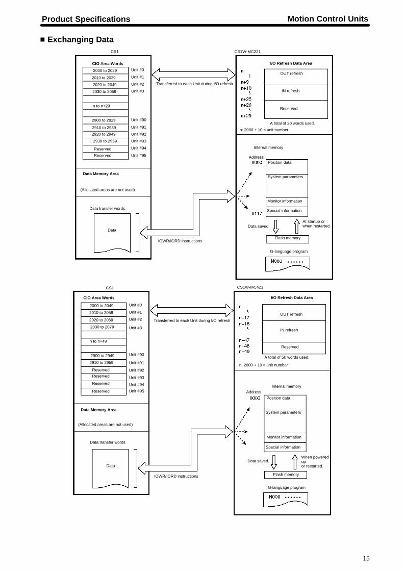
Exchanging Data
CS1
CIO Area Words
Unit #0
Unit #1
Unit #2
Unit #3
Unit #90
Unit #91
Unit #92
Unit #93
Unit #94
Unit #95
Reserved
Reserved
CS1W-MC221
Data Memory Area
(Allocated areas are not used)
Data
Data transfer words
IOWR/IORD instructions
Transferred to each Unit during I/O refresh
I/O Refresh Data Area
OUT refresh
IN refresh
Reserved
A total of 50 words used.
n: 2000 + 10 × unit number
Internal memoryAddress
Position data
System parameters
Monitor information
Special information
Data saved.When poweredup or restarted.
Flash memory
G-language program
CS1
CS1W-MC421
CIO Area Words
Unit #0
Unit #1
Unit #2
Unit #3
Unit #90
Unit #91
Unit #92
Unit #93
Unit #94
Unit #95
Reserved
Reserved
Data Memory Area
(Allocated areas are not used)
Data
Data transfer words
IOWR/IORD instructions
Transferred to each Unit during I/O refresh
I/O Refresh Data Area
OUT refresh
IN refresh
Reserved
A total of 30 words used.
n: 2000 + 10 × unit number
Internal memory
AddressPosition data
System parameters
Monitor information
Special information
Data saved.At startup orwhen restarted.
Flash memory
G-language program
Reserved
Reserved
2000 to 2029
2010 to 2039
2020 to 2049
2030 to 2059
n to n+29
2900 to 2929
2910 to 2939
2920 to 2949
2930 to 2959
2000 to 2049
2010 to 2059
2020 to 2069
2030 to 2079
n to n+49
2900 to 2949
2910 to 2959
� � � � � �
� � � � � �

Motion Control Units Product Specifications
16
Component NamesCS1W-MC221 CS1W-MC421
LED indicators LED indicators
Unit number setting switch Unit number setting switch
DRV X-Y connector10126-3000VE Connector
(Sumitomo 3M)10326-52F0-008 Connector cover
(Sumitomo 3M)(This unit is provided with 2 sets.)
I/O connectorTeaching Boxconnector
I/O connector
Teaching Boxconnector
MPG connector
DRV X-Y connector10126-3000VE Connector
(Sumitomo 3M)10326-52F0-008 Connector cover
(Sumitomo 3M)(This unit is provided with 2 sets.)
DRV Z-U connector10126-3000VE Connector
(Sumitomo 3M)10326-52F0-008 Connector cover
(Sumitomo 3M)(This unit is provided with 2 sets.)
�U
IndicatorsIndicator Color Status Meaning
RUN Green ON The MC Unit is operating normally.U G ee
OFF The MC Unit is not recognized by the PC or ismalfunctioning.
ERC Red ON An error occurred in the MC Unit.C ed
OFF The MC Unit is operating normally.
ERH Red ON An error occurred in the CPU Unit.
OFF The CPU Unit is operating normally.
XCCWYCCWZCCW (See note.)UCCW (S t )
Yellow ON The motor for the applicable axis is turning in the CCWdirection. (The X to U axes correspond to XCCW toUCCW.)( )
UCCW (See note.) OFF The applicable axis is stopped or is turning in the CWdirection.
XCWYCWZCW (S t )
Yellow ON The motor for the applicable axis is turning in the CWdirection. (The X to U axes correspond to XCW to UCW.)
ZCW (See note.)UCW (See note.) OFF The applicable axis is stopped or is turning in the CCW
direction.
Note: The CS1W-MC221 does not have the ZCCW, UCCW, ZCW, and UCW indicators.

Product Specifications Motion Control Units
17
I/O Connector WiringI/O ConnectorSnap-on ConnectorConnector: 10126-3000VE (provided with the Unit, manufactured by Sumitomo 3M)Case: 10326-52F0-008 (provided with the Unit, manufactured by Sumitomo 3M)
CS1W-MC221
Pin Symbol Terminal onMC Unit
terminal block
Name Function
1 +24 V 10 24-VDC input Connects to the + terminal of the24-VDC external power supply.
2 XCWL (NC) 11 X-axis CW limitinput
Limits movement of the X axis inthe CW direction.
3 YCWL (NC) 16 Y-axis CW limitinput
Limits movement of the Y axis inthe CW direction.
4 XCCWL (NC) 12 X-axis CCWlimit input
Limits movement of the X axis inthe CCW direction.
5 YCCWL (NC) 17 Y-axis CCWlimit input
Limits movement of the Y axis inthe CCW direction.
6 XSTOP (NC) 14 X-axisemergencystop input
Disables the X-axis run outputand stops it.
7 YSTOP (NC) 8 Y-axisemergencystop input
Disables the Y-axis run outputand stops it.
8 IN1 (NO) 4 General input 1 General input 1
9 IN2 (NO) 9 General input 2 General input 2
10 XORG (NC,NO) (See note 1)
13 X-axis originproximity input
Used for the X-axis originsearch.
11 YORG (NC,NO) (See note 1)
18 Y-axis originproximity input
Used for the Y-axis originsearch.
12 OUT1 (Seenote 3)
15 General output1
General output 1 or X-axis brakesignal output
13 OUT2 (Seenote 3)
19 General output2
General output 2 or Y-axis brakesignal output
14 DC GND 0 24-VDC inputground
Connects to the – terminal (0 V)of the 24-VDC external powersupply.
15 --- ---
16 MPG-A See note 2 MPG inputphase A
MPG inputphase A
See note 1
17 MPG-B See note 2 MPG inputphase B
MPG inputphase B
18 MPG-A See note 2 MPG inputphase A
MPG inputphase A
19 MPG-B See note 2 MPG inputphase B
MPG inputphase B
20 --- ---
21 IN3 (NO) See note 2 General input 3 General input 3
22 IN4 (NO) See note 2 General input 4 General input 4
23 --- ---
24 --- ---
25 OUT3 See note 2 General output3
General output 3
26 OUT4 See note 2 General output4
General output 4
“NC” stands for normally closed and “NO” stands for normally open.
Note: 1. For the CS1W-MC221, connect the MPG to this I/O connector. For the connection method, refer toMPG Connection Example on page 23.
2. MPG inputs, and general outputs 3 and 4 cannot be connected from the terminal block.
CS1W-MC221

Motion Control Units Product Specifications
18
CS1W-MC421
Pin Symbol Terminal on MCUnit terminal
block
Name Function
1 +24 V 20 24-VDC input Connects to the + terminal ofthe 24-VDC external powersupply.
2 XCWL (NC) 21 X-axis CW limitinput
Limits movement of the X axisin the CW direction.
3 YCWL (NC) 26 Y-axis CW limitinput
Limits movement of the Y axisin the CW direction.
4 XCCWL (NC) 22 X-axis CCWlimit input
Limits movement of the X axisin the CCW direction.
5 YCCWL (NC) 27 Y-axis CCWlimit input
Limits movement of the Y axisin the CCW direction.
6 XSTOP (NC) 24 X-axisemergencystop input
Disables the X-axis run outputand stops it.
7 YSTOP (NC) 8 Y-axisemergencystop input
Disables the Y-axis run outputand stops it.
8 IN1 (NO) 4 General input 1 General input 1
9 IN2 (NO) 9 General input 2 General input 2
10 XORG (NC, NO) (See note 1)
23 X-axis originproximity input
Used for the X-axis originsearch.
11 YORG (NC, NO) (See note 1)
28 Y-axis originproximity input
Used for the Y-axis originsearch.
12 OUT1 (See note 2) 25 General output1
General output 1 or X-axisbrake signal output
13 OUT2 (See note 2) 29 General output2
General output 2 or Y-axisbrake signal output
14 DC GND 0 24-VDC inputground
Connects to the – terminal (0V) of the 24-VDC externalpower supply.
15 ZCWL (NC) 31 (See note 5) Z-axis CW limitinput
Limits movement of the Z axisin the CW direction.
16 UCWL (NC) 36 (See note 3) U-axis CW limitinput
Limits movement of the U axisin the CW direction.
17 ZCCWL (NC) 32 (See note 3) Z-axis CCWlimit input
Limits movement of the Z axisin the CCW direction.
18 UCCWL (NC) 37 (See note 3) U-axis CCWlimit input
Limits movement of the U axisin the CCW direction.
19 ZSTOP (NC) 34 (See note 3) Z-axisemergencystop input
Disables the Z-axis run outputand stops it.
20 USTOP (NC) 18 (See note 5) U-axisemergencystop input
Disables the U-axis run outputand stops it.
21 IN3 (NO) 14 (See note 4) General input 3 General input 3
22 IN4 (NO) 19 (See note 4) General input 4 General input 4
23 ZORG (NC, NO) (See note 1)
33 (See note 5) Z-axis originproximity input
Used for the Z-axis originsearch.
24 UORG (NC, NO)(See note 1)
38 (See note 5) U-axis originproximity input
Used for the U-axis originsearch.
25 OUT3 35 (See note 4) General output3
General output 3
26 OUT4 39 (See note 4) General output4
General output 4
“NC” stands for normally closed and “NO” stands for normally open.
3. When the CS1W-MC221 and the XW2B-40J6-7 are connected, these terminals will be used asMPG inputs.
4. When the CS1W-MC221 and the XW2B-40J6-7 are connected, these terminals will be allocated asgeneral inputs/outputs 3 and 4.
5. When the CS1W-MC221 and the XW2B-40J6-7 are connected, these terminals will not be used.
CS1W-MC421

Product Specifications Motion Control Units
19
External Connection DiagramUsing the Connector
I/O connector
Pin
+24 V input
X-axis CW limit input
Y-axis CW limit input
X-axis CCW limit input
Y-axis CCW limit input
X-axis emergency stop input
Y-axis emergency stop input
General-purpose input 1
General-purpose input 2
X-axis origin proximity input
Y-axis origin proximity input
24-V input GND
Example: X-axis W iring
Emergency stop input
CCW limit input
CW limit input24 VDC
Origin proximityinput
Connector:Wire and assemble the connector byusing the connector case provided withthe Unit or by using the XW2Z-100J-F1MC Unit Terminal Block ConnectingCable.
+
–
Using the MC Unit T erminal Block
XW2Z-100J-F1 MC Unit Terminal Block Cable
MC Unit Terminal BlockCS1W-MC221: XW2B-20J6-6 CS1W-MC421: XW2B-40J6-7
X-axis CW, CCW, origin proximity, and emergency stopY-axis CW, CCW, origin proximity, and emergency stop
XW2B-20J6-6 MC Unit Terminal Block
Example: X-axis W iring
24 VDCEmergency stopinput
CCW limit input
CW limitinput
Origin proximityinput
24-VDC input ground
General input 1
24-VDC input
X-axis CW limit input
Y-axis CW limit input
X-axis CCW limit input
Y-axis CCW limit input
X-axis emergency stop input
Y-axis emergency stop input
General input 2
X-axis origin proximity input
Y-axis origin proximity input
+
–

Motion Control Units Product Specifications
20
DRV Connector WiringDRV X-Y and Z-U ConnectorsThe DRV connectors are used primarily to connect servodrivers. The DRV X-Y connector is for the X and Y axes, and the DRV Z-U connector isfor the Z and U axes.Special driver cables, which are sold separately, are available for OMRON U-, H-, and M-series Servodrivers.Snap-on Connectors
Connector: 10136-3000VE (provided with the Unit, manufactured by Sumitomo 3M)Case: 10336-52F0-008 (provided with the Unit, manufactured by Sumitomo 3M)
CS1W-MC221
Pin Symbol Name Function
1 +24 V 24 VDC input External power supply’s 24-VDCinput (for the X-Y axes)
2 DC GND 24 VDC input ground External power supply’s 24-VDCground (for the X-Y axes)
3 XALM X-axis alarm input Driver alarm input for the X-axis
4 XRUN X-axis run output Driver run output for the X-axis
5 XALMRS X-axis alarm resetoutput
Reset output for the X-axis’s driveralarm.
6 --- --- Not used.
7 --- --- Not used.
8 XSGND X-axis SEN signalground
SEN signal ground for the X-axis
9 XSOUT X-axis SEN signaloutput
SEN signal output for the X-axis(absolute encoder driver)
10 X-GND X-axis feedback ground Feedback ground for the X-axis
11 X-A X-axis phase A input Phase A feedback input for the X-axis
12 X-A X-axis phase A input Phase A feedback input for the X-axis
13 X-B X-axis phase B input Phase B feedback input for the X-axis
14 X-B X-axis phase B input Phase B feedback input for the X-axis
15 X-Z X-axis phase Z input Phase Z feedback input for the X-axis
16 X-Z X-axis phase Z input Phase Z feedback input for the X-axis
17 XOUT X-axis speed control Speed control voltage to the X-axisdriver
18 XAGND X-axis speed controlground
Ground for the X-axis’s speed controlvoltage
19 +F24V 24 VDC output 24-VDC input to the driver (for theX-Y axes)
20 FDC GND 24 VDC output ground Ground for 24-VDC outputs (for theX-Y axes)
21 YALM Y-axis alarm input Driver alarm input for the Y-axis
22 YRUN Y-axis run output Driver run output for the Y-axis
23 YALMRS Y-axis alarm resetoutput
Reset output for the Y-axis’s driveralarm.
24 --- --- Not used.
25 --- --- Not used.
26 YSGND Y-axis SEN signalground
SEN signal ground for the Y-axis
27 YSOUT Y-axis SEN signaloutput
SEN signal output for the Y-axis(absolute encoder driver)
28 Y-GND Y-axis feedback ground Feedback ground for the Y-axis
29 Y-A Y-axis phase A input Phase A feedback input for the Y-axis
30 Y-A Y-axis phase A input Phase A feedback input for the Y-axis
31 Y-B Y-axis phase B input Phase B feedback input for the Y-axis
32 Y-B Y-axis phase B input Phase B feedback input for the Y-axis
33 Y-Z Y-axis phase Z input Phase Z feedback input for the Y-axis
34 Y-Z Y-axis phase Z input Phase Z feedback input for the Y-axis
35 YOUT Y-axis speed control Speed control voltage to the Y-axisdriver
36 YAGND Y-axis speed controlground
Ground for the Y-axis’s speed controlvoltage
CS1W-MC221

Product Specifications Motion Control Units
21
CS1W-MC421
Pin Symbol Name Function
1 +24 V 24 VDC input External power supply’s 24-VDC input (forthe Z-U axes)
2 DC GND 24 VDC inputground
External power supply’s 24-VDC ground(for the Z-U axes)
3 ZALM Z-axis alarm input Driver alarm input for the Z-axis
4 ZRUN Z-axis run output Driver run output for the Z-axis
5 ZALMRS Z-axis alarm resetoutput
Reset output for the Z-axis’s driver alarm.
6 --- --- Not used.
7 --- --- Not used.
8 ZSGND Z-axis SEN signalground
SEN signal ground for the Z-axis
9 ZSOUT Z-axis SEN signaloutput
SEN signal output for the Z-axis (absoluteencoder driver)
10 Z-GND Z-axis feedbackground
Feedback ground for the Z-axis
11 Z-A Z-axis phase A input Phase A feedback input for the Z-axis
12 Z-A Z-axis phase A input Phase A feedback input for the Z-axis
13 Z-B Z-axis phase B input Phase B feedback input for the Z-axis
14 Z-B Z-axis phase B input Phase B feedback input for the Z-axis
15 Z-Z Z-axis phase Z input Phase Z feedback input for the Z-axis
16 Z-Z Z-axis phase Z input Phase Z feedback input for the Z-axis
17 ZOUT Z-axis speed control Speed control voltage to the Z-axis driver
18 ZAGND Z-axis speed controlground
Ground for the Z-axis’s speed controlvoltage
19 +F24V 24 VDC output 24-VDC input to the driver (for the Z-Uaxes)
20 FDC GND 24 VDC outputground
Ground for 24-VDC outputs (for the Z-Uaxes)
21 UALM U-axis alarm input Driver alarm input for the U-axis
22 URUN U-axis run output Driver run output for the U-axis
23 UALMRS U-axis alarm resetoutput
Reset output for the U-axis’s driver alarm.
24 --- --- Not used.
25 --- --- Not used.
26 USGND U-axis SEN signalground
SEN signal ground for the U-axis
27 USOUT U-axis SEN signaloutput
SEN signal output for the U-axis (absoluteencoder driver)
28 U-GND U-axis feedbackground
Feedback ground for the U-axis
29 U-A U-axis phase Ainput
Phase A feedback input for the U-axis
30 U-A U-axis phase Ainput
Phase A feedback input for the U-axis
31 U-B U-axis phase Binput
Phase B feedback input for the U-axis
32 U-B U-axis phase Binput
Phase B feedback input for the U-axis
33 U-Z U-axis phase Zinput
Phase Z feedback input for the U-axis
34 U-Z U-axis phase Zinput
Phase Z feedback input for the U-axis
35 UOUT U-axis speed control Speed control voltage to the U-axis driver
36 UAGND U-axis speed controlground
Ground for the U-axis’s speed controlvoltage
CS1W-MC421

Motion Control Units Product Specifications
22
Servodriver Cables (Optional)When using OMRON’s U-, H-, or M-series Servodrivers, use Special Servodriver Cables that areavailable as options to connect the MC Unit to Servodrivers.
Series Cable model number Length (m)Se es
For two axes For single axis
e g ( )
U-series R88D-Ufor 30-W to
R88A-CPU001M2 R88A-CPU001M1 1.0for 30 W to750-WServodrivers
R88A-CPU002M2 R88A-CPU002M1 2.0
R88D-Ufor 1-W to
R88A-CPUB001M2 R88A-CPUB001M1 1.0for 1 W to5-kWServodrivers
R88A-CPUB002M2 R88A-CPUB002M1 2.0
H-series R88D-H R88A-CPH001M2 R88A-CPH001M1 1.0se es 88
R88A-CPH002M2 R88A-CPH002M1 2.0
M-series R88D-M R88A-CPM001M2 R88A-CPM001M1 1.0se es 88
R88A-CPM002M2 R88A-CPM002M1 2.0
Connect to a battery when using theabsolute encoder.
Connect to +24 V
Servodriver
Servodriver
Connect to +24 V Connect to +24 V
U-series Servodrivers:R88A-CPU001M2/002M2 (30 to 750 W)R88A-CPUB001M2/002M2 (1 to 5 kW)
H-series Servodrivers:R88A-CPH001M2/002M2
M-series Servodrivers:R88A-CPM001M2/002M2
DRV X-Yconnector
DRV X-Yconnector
Servodriver
Servodriver
Servodriver
Servodriver
DRV X-Yconnector
Connector:When the Special Cables shown onthe left are not to be used, wire andassemble the connector by usingthe connector case provided withthe Unit.

Product Specifications Motion Control Units
23
Connection ExamplesConnection to U-series (30-W to 750-W) Models (Using an Absolute Encoder)Special Driver Cable: R88A-CPU00�M2
24-VDC output ground
DRV X-Y connector
MC Unit
AC ServodriverR88D-UA���
DC Power SupplyRed
BlackCN1
Y-axis speed control ground
AC ServodriverR88D-UA���
Battery(+2.8 to 4.5 V)
+
+24V
+24V
Red
BlackBattery(+2.8 to 4.5 V)
RedBlack
+24V
+A
–A+B
–B+Z
–Z
+A
–A+B
–B+Z
–Z
24-VDC input24-VDC input ground
X-axis alarm inputX-axis run output
X-axis alarm reset output
X-axis SEN signal groundX-axis SEN signal output
X-axis feedback groundX-axis phase A input
X-axis phase A inputX-axis phase B input
X-axis phase B inputX-axis phase Z inputX-axis phase Z input
X-axis speed controlX-axis speed control ground
24-VDC output
Y-axis alarm inputY-axis run output
Y-axis alarm reset output
Y-axis SEN signal ground
Y-axis feedback ground
Y-axis phase A inputY-axis phase A input
Y-axis phase B inputY-axis phase B inputY-axis phase Z inputY-axis phase Z input
Y-axis speed control
Y-axis SEN signal output
+
MPG Connector WiringMPG Connector (for CS1W-MC421 Only)The MPG connector is used to connect a manual pulse generator (MPG). With the CS1W-MC421, it is wired with an MPG connector. With theCS1W-MC221, there is an MPG terminal on the I/O connector.
Manual Pulse Generator (MPG)Use a line driver model for the MPG. The LGF-003-100 (by Sumtak) is recommended.Snap-on ConnectorsConnector: 10114-3000VE (provided with the Unit, manufactured by Sumitomo 3M)Case: 10314-52F0-008 (provided with the Unit, manufactured by Sumitomo 3M)
Pin Symbol Name
5 MPG-A MPG input phase A
6 MPG-A MPG input phase A
12 MPG-B MPG input phase B
13 MPG-B MPG input phase B
CS1W-MC421

Motion Control Units Product Specifications
24
MPG Connection Example
CS1W-MC421MPG connector
MPG input phase A
MPG input phase A
MPG input phase B
MPG input phase B
5 VDCPower supply
MPG (LGF-003-100)
CS1W-MC221I/O connector
MPG input phase A
MPG input phase A
MPG input phase B
MPG input phase B
MPG (LGF-003-100)
Note: For the CS1W-MC221, use the I/O connector.
+
–
6
5
13
12
5 VDCPower supply
+
–
16
18
17
19
ALL DIMENSIONS SHOWN ARE IN MILLIMETERS.To convert millimeters into inches, multiply by 0.03937. To convert grams into ounces, multiply by 0.03527.

OMRON CorporationSystems Components Division66 Matsumoto Mishima-city, Shizuoka 411-8511 JapanTel: (81)559-77-9633Fax: (81)559-77-9097
Regional Headquarters
OMRON EUROPE B.V.Wegalaan 67-69, NL-2132 JD HoofddorpThe NetherlandsTel: (31)2356-81-300/Fax: (31)2356-81-388
OMRON ELECTRONICS, INC.1 East Commerce Drive, Schaumburg, IL 60173U.S.A.Tel: (1)847-843-7900/Fax: (1)847-843-8568
OMRON ASIA PACIFIC PTE. LTD.83 Clemenceau Avenue, #11-01, UE Square,Singapore 239920Tel: (65)835-3011/Fax: (65)835-2711
Authorized Distributor:
Note: Specifications subject to change without notice.
Cat. No. R062-E1-1 Printed in Japan0100-0.7M