Embed Size (px)
Citation preview

Name ___________________________________
1
Computer Architecture and Engineering
CS152 Quiz #1
Wed, February 17th, 2016
Professor George Michelogiannakis
Name: _____<ANSWER KEY>_____
This is a closed book, closed notes exam.
80 Minutes. 18 pages
Notes:
Not all questions are of equal difficulty, so look over the entire exam
and budget your time carefully.
Please carefully state any assumptions you make.
Please write your name on every page in the quiz.
You must not discuss a quiz’s contents with other students who have not taken the quiz. If you have inadvertently been exposed to a quiz prior to taking it,
you must tell the instructor or TA.
You will get no credit for selecting multiple-choice answers without
giving explanations if the instructions ask you to explain your choice.
Writing name on each sheet ________________ 1 Point
Question 1 ________________ 25 Points
Question 2 ________________ 30 Points
Question 3 ________________ 28 Points
Question 4 ________________ 16 Points
TOTAL ________________ 100 Points
Name ___________________________________
2
Question 1: Microprogramming [25 points]
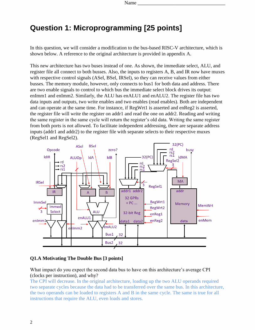
In this question, we will consider a modification to the bus-based RISC-V architecture, which is
shown below. A reference to the original architecture is provided in appendix A.
This new architecture has two buses instead of one. As shown, the immediate select, ALU, and
register file all connect to both busses. Also, the inputs to registers A, B, and IR now have muxes
with respective control signals (ASel, BSel, IRSel), so they can receive values from either
busses. The memory module, however, only connects to bus1 for both data and address. There
are two enable signals to control to which bus the immediate select block drives its output:
enImm1 and enImm2. Similarly, the ALU has enALU1 and enALU2. The register file has two
data inputs and outputs, two write enables and two enables (read enables). Both are independent
and can operate at the same time. For instance, if RegWrt1 is asserted and enReg2 is asserted,
the register file will write the register on addr1 and read the one on addr2. Reading and writing
the same register in the same cycle will return the register’s old data. Writing the same register
from both ports is not allowed. To facilitate independent addressing, there are separate address
inputs (addr1 and addr2) to the register file with separate selects to their respective muxes
(RegSel1 and RegSel2).
Q1.A Motivating The Double Bus [3 points]
What impact do you expect the second data bus to have on this architecture’s average CPI
(clocks per instruction), and why?
The CPI will decrease. In the original architecture, loading up the two ALU operands required
two separate cycles because the data had to be transferred over the same bus. In this architecture,
the two operands can be loaded to registers A and B in the same cycle. The same is true for all
instructions that require the ALU, even loads and stores.
Name ___________________________________
3
Q1.B Implementing a New Instruction [18 points]
For this question, you will implement the microcode for a new instruction in worksheet Q1-1
provided in the next page. The new instruction is a memory-register ALU operation, and has the
form:
ALUM rd, rs1, rs2
This instruction reads the memory at the address specified by rs1. It performs the ALU operation
between that value and the value of rs2. Then it records the result to rd. In other words, in the
example of an addition:
Reg[rd] <= Mem[Reg[rs1]] + Reg[Rs2]
In the worksheet, use don’t cares (*) where appropriate. For signals that have two versions, one
for each bus (RegSel has RegSel1 and RegSel2, and the same for RegWr, EnReg, enALU,
enImm), write which one will be asserted. For example, writing “1” under RegSel means that
RegSel1 will be asserted only. Writing “1&2” means both RegSel1 and RegSel2 will be asserted.
For multi-bit signals like RegSel, just write the two values. For instance, for RegSel you can
write “PC, PC” to select the PC for both. Those signals are shown in red and are underlined.
Your solution should use the fewest cycles possible by exploiting the two busses. In the “μBR”
field, N means next state, S means spin, D means dispatch, and J means jump. If you need to add
a state please explain clearly. You can assume the memory returns data after a read at the next
cycle.
Please comment your code. If your code does not fit in the provided worksheet, you can write in
the margins as long as you do so neatly. Your code should exhibit “clean” behavior and not
modify any ISA-visible registers (except the PC register and the rd register) in the course of
executing the instruction. You will receive credit for elegance and efficiency. Finally, make sure
that your microcode sequence fetches the next instruction in program order (i.e., by doing a
microbranch to FETCH0 as discussed in the handout).
Name ___________________________________
4
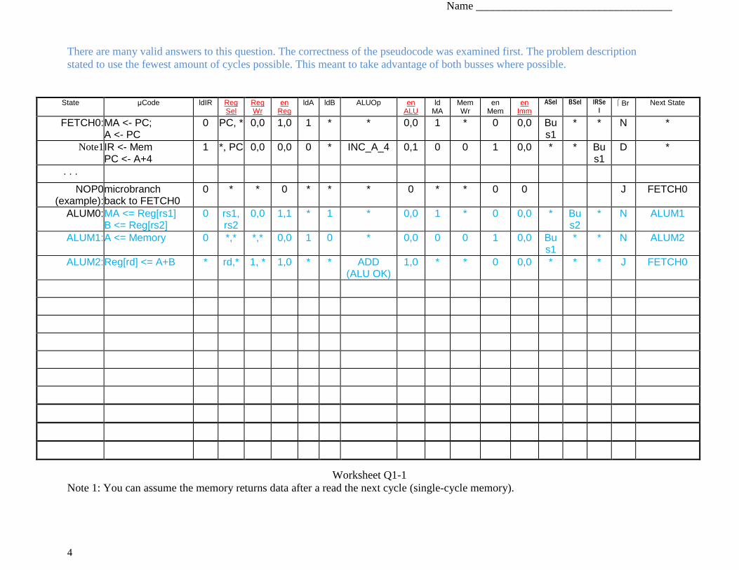
There are many valid answers to this question. The correctness of the pseudocode was examined first. The problem description
stated to use the fewest amount of cycles possible. This meant to take advantage of both busses where possible.
Worksheet Q1-1
Note 1: You can assume the memory returns data after a read the next cycle (single-cycle memory).
State μCode ldIR Reg Sel
Reg Wr
en Reg
ldA ldB ALUOp en ALU
ld MA
Mem Wr
en Mem
en Imm
ASel BSel IRSe
l Br Next State
FETCH0: MA <- PC; A <- PC
0 PC, * 0,0 1,0 1 * * 0,0 1 * 0 0,0 Bus1
* * N *
Note1 IR <- Mem PC <- A+4
1 *, PC 0,0 0,0 0 * INC_A_4 0,1 0 0 1 0,0 * * Bus1
D *
. . .
NOP0 (example):
microbranch back to FETCH0
0 * * 0 * * * 0 * * 0 0 J FETCH0
ALUM0: MA <= Reg[rs1] B <= Reg[rs2]
0 rs1, rs2
0,0 1,1 * 1 * 0,0 1 * 0 0,0 * Bus2
* N ALUM1
ALUM1: A <= Memory 0 *,* *,* 0,0 1 0 * 0,0 0 0 1 0,0 Bus1
* * N ALUM2
ALUM2: Reg[rd] <= A+B * rd,* 1, * 1,0 * * ADD (ALU OK)
1,0 * * 0 0,0 * * * J FETCH0
Name ___________________________________
5
Q1.C Comparing Microcode ROM Sizes [4 points]
Let us compare the microcode ROM from the original microcoded bus-based RISC-V processor
that is shown in Appendix A, and the one for the modified processor we consider in this
question. Recall that the microcode ROM contains the necessary states (microinstructions) as
well as drives the control signals in worksheet Q1-1.
Compare the height (number of entries) as well as width (bits in each entry) of the microcoded
ROM of the modified processor, with the original processor. Does the modified processor
require a taller and/or wider ROM? Explain your answer.
The modified processor requires fewer states per instruction (as shown in the example of ALU
above). Therefore, we need fewer overall states, thus fewer ROM entries, thus the ROM is
shorter than the original microcoded bus-based processor. However, in the modified processor
each state has more output control signals, thus it is wider.
Name ___________________________________
6
Question 2: Branch Prediction and Exceptions [30 points]
For this question, consider a fully bypassed 5-stage RISC-V processor (as shown in Lecture 4,
Appendix B, and used in Lab 1). We have reproduced the pipeline diagram in Appendix B
(bypasses are not shown). The fetch stage always speculates that the next PC is PC+4.
Remember that branch instructions take as argument source registers and calculate the next PC
as an offset from the current (the branch instruction’s) PC. For instance, BEQ rs1, rs2, offset is
taken if rs1 == rs2. In that case, the new PC is PC <= PC + (offset << 1). Similarly, BNE is taken
if rs1 != rs2, BGE if rs1 >= rs2, and BLT if rs1 < rs2. For simplicity in the code segments we see
below, we will ignore the hide the left shift by using labels. So branch to “foo” will branch (if
taken) to label “foo:” found in the code.
Q2.A Motivating Branch Prediction [10 points]
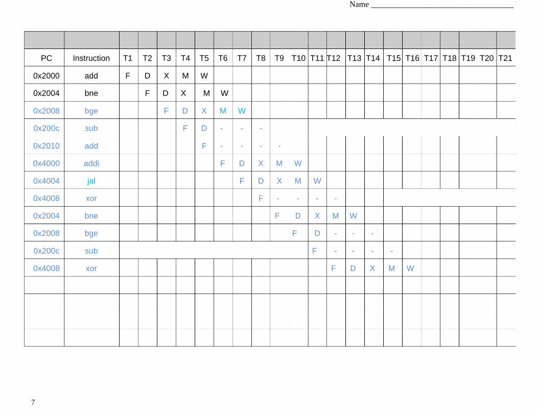
To understand the pipeline behavior, please fill out the following instruction/time diagram for the
following set of instructions until the instruction in 0x4008 (xor) fully executes and commits.
Execution starts from 0x2000.
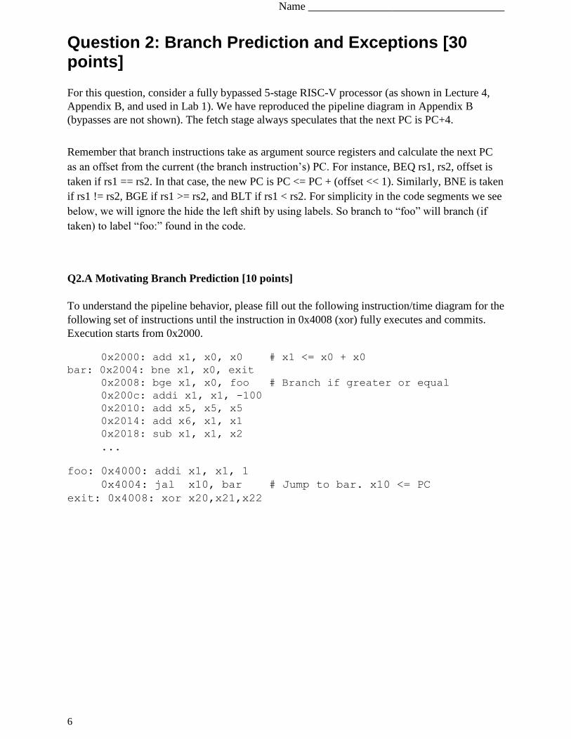
0x2000: add x1, x0, x0 # x1 <= x0 + x0
bar: 0x2004: bne x1, x0, exit
0x2008: bge x1, x0, foo # Branch if greater or equal
0x200c: addi x1, x1, -100
0x2010: add x5, x5, x5
0x2014: add x6, x1, x1
0x2018: sub x1, x1, x2 ...
foo: 0x4000: addi x1, x1, 1
0x4004: jal x10, bar # Jump to bar. x10 <= PC exit: 0x4008: xor x20,x21,x22
Name ___________________________________
7
PC Instruction T1 T2 T3 T4 T5 T6 T7 T8 T9 T10 T11 T12 T13 T14 T15 T16 T17 T18 T19 T20 T21
0x2000 add F D X M W
0x2004 bne F D X M W
0x2008 bge F D X M W
0x200c sub F D - - -
0x2010 add F - - - -
0x4000 addi F D X M W
0x4004 jal F D X M W
0x4008 xor F - - - -
0x2004 bne F D X M W
0x2008 bge F D - - -
0x200c sub F - - - -
0x4008 xor F D X M W
Name ___________________________________
8
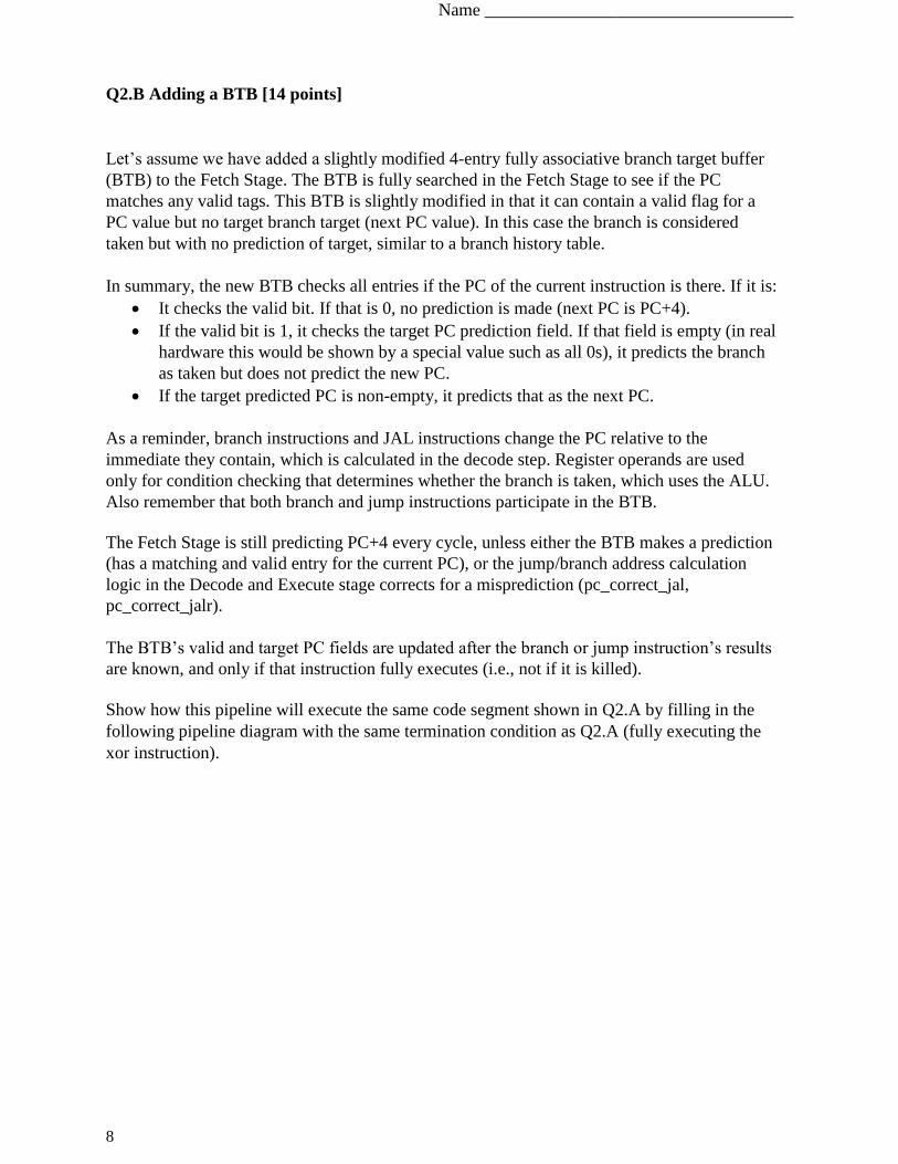
Q2.B Adding a BTB [14 points]
Let’s assume we have added a slightly modified 4-entry fully associative branch target buffer
(BTB) to the Fetch Stage. The BTB is fully searched in the Fetch Stage to see if the PC
matches any valid tags. This BTB is slightly modified in that it can contain a valid flag for a
PC value but no target branch target (next PC value). In this case the branch is considered
taken but with no prediction of target, similar to a branch history table.
In summary, the new BTB checks all entries if the PC of the current instruction is there. If it is:
It checks the valid bit. If that is 0, no prediction is made (next PC is PC+4).
If the valid bit is 1, it checks the target PC prediction field. If that field is empty (in real
hardware this would be shown by a special value such as all 0s), it predicts the branch
as taken but does not predict the new PC.
If the target predicted PC is non-empty, it predicts that as the next PC.
As a reminder, branch instructions and JAL instructions change the PC relative to the
immediate they contain, which is calculated in the decode step. Register operands are used
only for condition checking that determines whether the branch is taken, which uses the ALU.
Also remember that both branch and jump instructions participate in the BTB.
The Fetch Stage is still predicting PC+4 every cycle, unless either the BTB makes a prediction
(has a matching and valid entry for the current PC), or the jump/branch address calculation
logic in the Decode and Execute stage corrects for a misprediction (pc_correct_jal,
pc_correct_jalr).
The BTB’s valid and target PC fields are updated after the branch or jump instruction’s results
are known, and only if that instruction fully executes (i.e., not if it is killed).
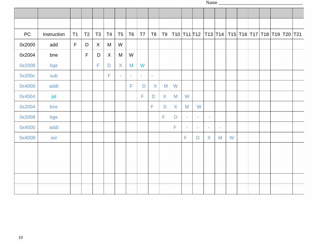
Show how this pipeline will execute the same code segment shown in Q2.A by filling in the
following pipeline diagram with the same termination condition as Q2.A (fully executing the
xor instruction).
Name ___________________________________
9
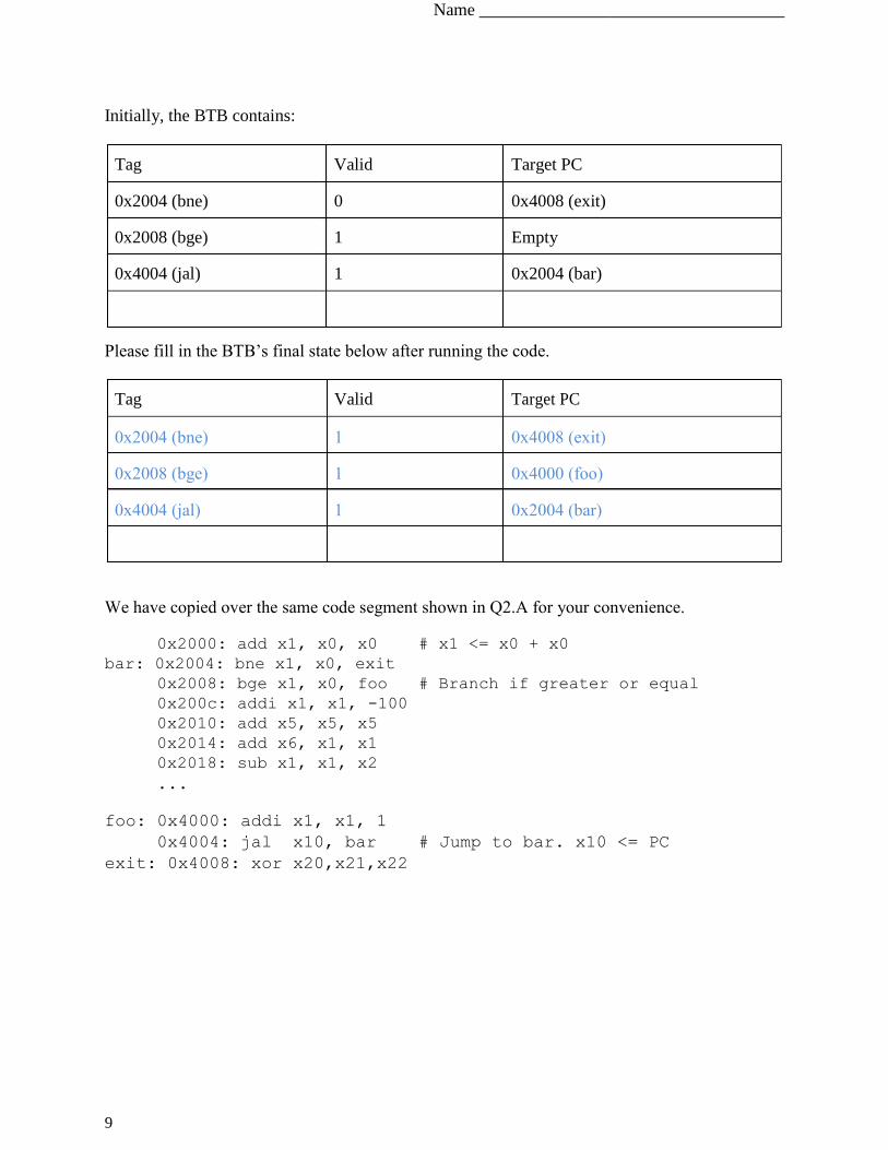
Initially, the BTB contains:
Tag Valid Target PC
0x2004 (bne) 0 0x4008 (exit)
0x2008 (bge) 1 Empty
0x4004 (jal) 1 0x2004 (bar)
Please fill in the BTB’s final state below after running the code.
Tag Valid Target PC
0x2004 (bne) 1 0x4008 (exit)
0x2008 (bge) 1 0x4000 (foo)
0x4004 (jal) 1 0x2004 (bar)
We have copied over the same code segment shown in Q2.A for your convenience.
0x2000: add x1, x0, x0 # x1 <= x0 + x0
bar: 0x2004: bne x1, x0, exit
0x2008: bge x1, x0, foo # Branch if greater or equal
0x200c: addi x1, x1, -100
0x2010: add x5, x5, x5
0x2014: add x6, x1, x1
0x2018: sub x1, x1, x2 ...
foo: 0x4000: addi x1, x1, 1
0x4004: jal x10, bar # Jump to bar. x10 <= PC exit: 0x4008: xor x20,x21,x22
Name ___________________________________
10
PC Instruction T1 T2 T3 T4 T5 T6 T7 T8 T9 T10 T11 T12 T13 T14 T15 T16 T17 T18 T19 T20 T21
0x2000 add F D X M W
0x2004 bne F D X M W
0x2008 bge F D X M W
0x200c sub F - - - -
0x4000 addi F D X M W
0x4004 jal F D X M W
0x2004 bne F D X M W
0x2008 bge F D - - -
0x4000 addi F - - - -
0x4008 xor F D X M W

Name ___________________________________
11
Q2.C Exceptions [6 points]
Let’s assume that a branch is mispredicted to be non-taken. Thus, the next instruction enters the
pipeline before being flushed, and makes it into the decode step. If that instruction has an illegal
opcode which would raise an exception, how should the pipeline react? Explain how the pipeline
will handle this and why.
Even though an exception would be raised, the kill signal should take precedence and kill the
instruction that would cause the exception, as well as suppress the exception. That instruction
should not change the state of the processor and raising an exception can potentially do so.
Now let’s assume that the first time the instruction in PC 0x2008 executes (bge), it raises an
exception. If our pipeline provides precise exceptions, what must the value of x1 be by the
time the pipeline is flushed and the handler executes?
Only instructions before 0x2008 have executed and committed with precise exceptions, so x1
must be 0.
If we have imprecise exceptions what can the value of x1 be?
x1 could be 0, could be 1 (if the addi later executes), or have any other value if execution has
progressed beyond 0x4008 which is the end of our timing diagrams.
Name ___________________________________
12
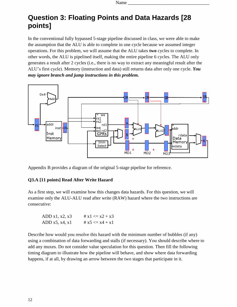
Question 3: Floating Points and Data Hazards [28 points]
In the conventional fully bypassed 5-stage pipeline discussed in class, we were able to make
the assumption that the ALU is able to complete in one cycle because we assumed integer
operations. For this problem, we will assume that the ALU takes two cycles to complete. In
other words, the ALU is pipelined itself, making the entire pipeline 6 cycles. The ALU only
generates a result after 2 cycles (i.e., there is no way to extract any meaningful result after the
ALU’s first cycle). Memory (instruction and data) still returns data after only one cycle. You
may ignore branch and jump instructions in this problem.
Appendix B provides a diagram of the original 5-stage pipeline for reference.
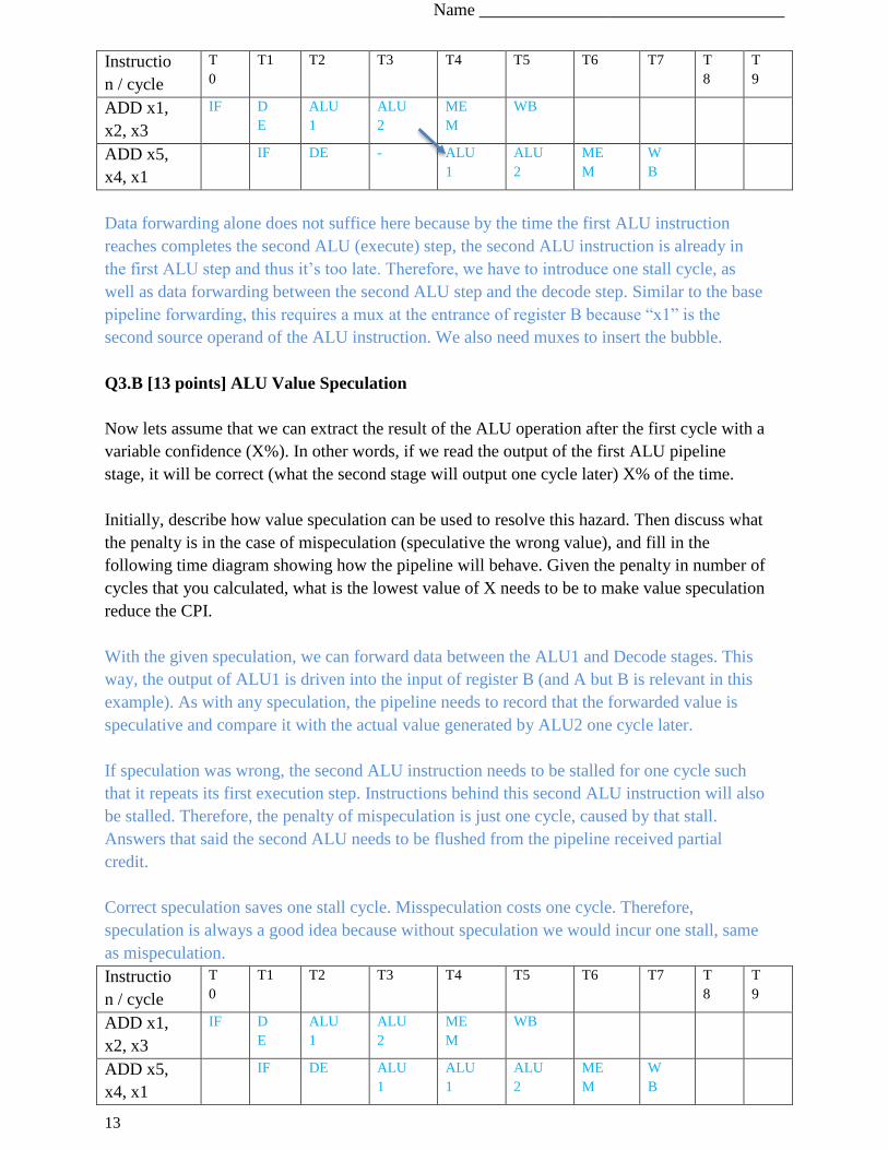
Q3.A [11 points] Read After Write Hazard
As a first step, we will examine how this changes data hazards. For this question, we will
examine only the ALU-ALU read after write (RAW) hazard where the two instructions are
consecutive:
ADD x1, x2, x3 # x1 <= x2 + x3
ADD x5, x4, x1 # x5 <= x4 + x1
Describe how would you resolve this hazard with the minimum number of bubbles (if any)
using a combination of data forwarding and stalls (if necessary). You should describe where to
add any muxes. Do not consider value speculation for this question. Then fill the following
timing diagram to illustrate how the pipeline will behave, and show where data forwarding
happens, if at all, by drawing an arrow between the two stages that participate in it.
Name ___________________________________
13
Instructio
n / cycle
T
0
T1 T2 T3 T4 T5 T6 T7 T
8
T
9
ADD x1,
x2, x3
IF D
E
ALU
1
ALU
2
ME
M
WB
ADD x5,
x4, x1
IF DE - ALU
1
ALU
2
ME
M
W
B
Data forwarding alone does not suffice here because by the time the first ALU instruction
reaches completes the second ALU (execute) step, the second ALU instruction is already in
the first ALU step and thus it’s too late. Therefore, we have to introduce one stall cycle, as
well as data forwarding between the second ALU step and the decode step. Similar to the base
pipeline forwarding, this requires a mux at the entrance of register B because “x1” is the
second source operand of the ALU instruction. We also need muxes to insert the bubble.
Q3.B [13 points] ALU Value Speculation
Now lets assume that we can extract the result of the ALU operation after the first cycle with a
variable confidence (X%). In other words, if we read the output of the first ALU pipeline
stage, it will be correct (what the second stage will output one cycle later) X% of the time.
Initially, describe how value speculation can be used to resolve this hazard. Then discuss what
the penalty is in the case of mispeculation (speculative the wrong value), and fill in the
following time diagram showing how the pipeline will behave. Given the penalty in number of
cycles that you calculated, what is the lowest value of X needs to be to make value speculation
reduce the CPI.
With the given speculation, we can forward data between the ALU1 and Decode stages. This
way, the output of ALU1 is driven into the input of register B (and A but B is relevant in this
example). As with any speculation, the pipeline needs to record that the forwarded value is
speculative and compare it with the actual value generated by ALU2 one cycle later.
If speculation was wrong, the second ALU instruction needs to be stalled for one cycle such
that it repeats its first execution step. Instructions behind this second ALU instruction will also
be stalled. Therefore, the penalty of mispeculation is just one cycle, caused by that stall.
Answers that said the second ALU needs to be flushed from the pipeline received partial
credit.
Correct speculation saves one stall cycle. Misspeculation costs one cycle. Therefore,
speculation is always a good idea because without speculation we would incur one stall, same
as mispeculation.
Instructio
n / cycle
T
0
T1 T2 T3 T4 T5 T6 T7 T
8
T
9
ADD x1,
x2, x3
IF D
E
ALU
1
ALU
2
ME
M
WB
ADD x5,
x4, x1
IF DE ALU
1
ALU
1
ALU
2
ME
M
W
B
Name ___________________________________
14
Q3.C [4 points] Merging Pipeline Stages
Instead of pipelining the ALU, you have the option of leaving the ALU in a single pipeline
step, and instead merge the fetch and decode stages, as well as memory and writeback stages.
This will result in a 3-stage pipeline. Do you expect this 3-stage pipeline to have a lower,
higher, or equal CPI and why?
The CPI should be lower (higher performance) because shallower pipelines have fewer cases
where stalls are necessary. In the particular example of the two previous questions, the
shallow pipeline does not need to stall in the same dependency, neither does it need to resort
to ALU value speculation that may cause pipeline flushing. It’s important to note that there
are fewer hazards, but really no stalls. Hazards by themselves do not affect the CPI if we can
forward effectively.
Name ___________________________________
15
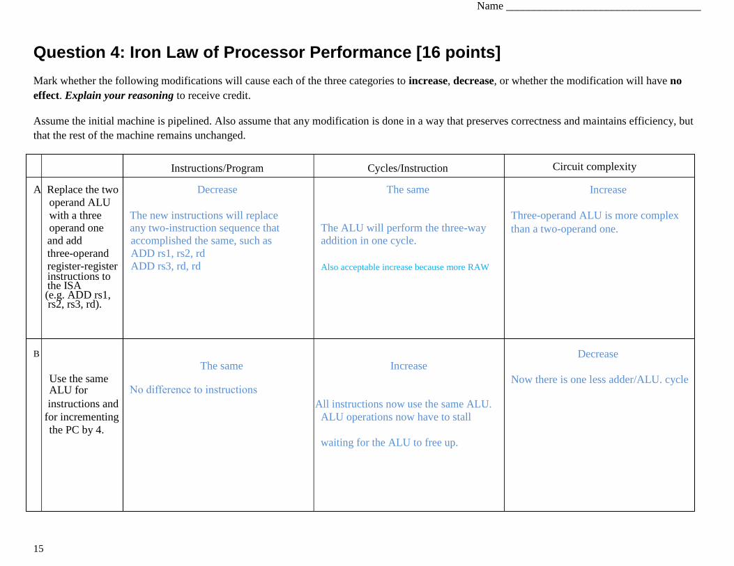
Question 4: Iron Law of Processor Performance [16 points]
Mark whether the following modifications will cause each of the three categories to increase, decrease, or whether the modification will have no
effect. Explain your reasoning to receive credit.
Assume the initial machine is pipelined. Also assume that any modification is done in a way that preserves correctness and maintains efficiency, but
that the rest of the machine remains unchanged.
Instructions/Program Cycles/Instruction
A Replace the two Decrease The same
operand ALU
with a three operand one
The new instructions will replace any two-instruction sequence that The ALU will perform the three-way
and add accomplished the same, such as addition in one cycle.
three-operand
register-register
ADD rs1, rs2, rd
ADD rs3, rd, rd Also acceptable increase because more RAW instructions to the ISA (e.g. ADD rs1, rs2, rs3, rd).
B
The same Increase
Use the same
No difference to instructions
ALU for
instructions and All instructions now use the same ALU.
for incrementing ALU operations now have to stall
the PC by 4.
waiting for the ALU to free up.
Circuit complexity
Increase
Three-operand ALU is more complex
than a two-operand one.
Decrease
Now there is one less adder/ALU. cycle
Name ___________________________________
16
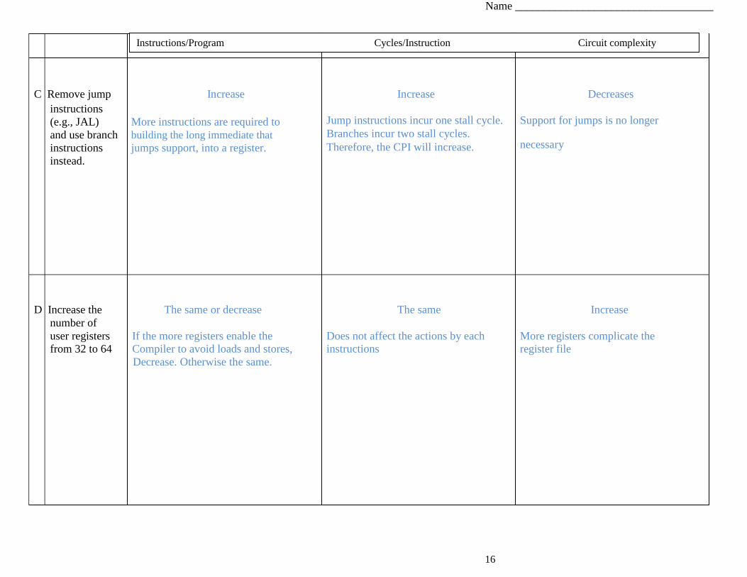
C Remove jump Increase instructions
(e.g., JAL) More instructions are required to
and use branch building the long immediate that
instructions jumps support, into a register.
instead.
Increase
Jump instructions incur one stall cycle.
Branches incur two stall cycles.
Therefore, the CPI will increase.
Decreases
Support for jumps is no longer
necessary
D Increase the The same or decrease The same Increase
number of
user registers If the more registers enable the Does not affect the actions by each More registers complicate the
from 32 to 64 Compiler to avoid loads and stores, instructions register file
Decrease. Otherwise the same.
Instructions/Program Cycles/Instruction Circuit complexity
Name ___________________________________
17
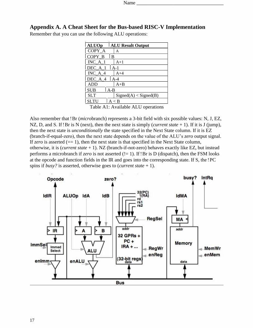
Appendix A. A Cheat Sheet for the Bus-based RISC-V Implementation Remember that you can use the following ALU operations:
ALUOp ALU Result Output COPY_A A
COPY_B B
INC_A_1 A+1
DEC_A_1 A-1
INC_A_4 A+4
DEC_A_4 A-4
ADD A+B
SUB A-B
SLT Signed(A) < Signed(B)
SLTU A < B Table A1: Available ALU operations
Also remember that Br (microbranch) represents a 3-bit field with six possible values: N, J, EZ,
NZ, D, and S. If Br is N (next), then the next state is simply (current state + 1). If it is J (jump),
then the next state is unconditionally the state specified in the Next State column. If it is EZ
(branch-if-equal-zero), then the next state depends on the value of the ALU’s zero output signal.
If zero is asserted (== 1), then the next state is that specified in the Next State column,
otherwise, it is (current state + 1). NZ (branch-if-not-zero) behaves exactly like EZ, but instead
performs a microbranch if zero is not asserted (!= 1). If Br is D (dispatch), then the FSM looks
at the opcode and function fields in the IR and goes into the corresponding state. If S, the PC
spins if busy? is asserted, otherwise goes to (current state + 1).
Name ___________________________________
18
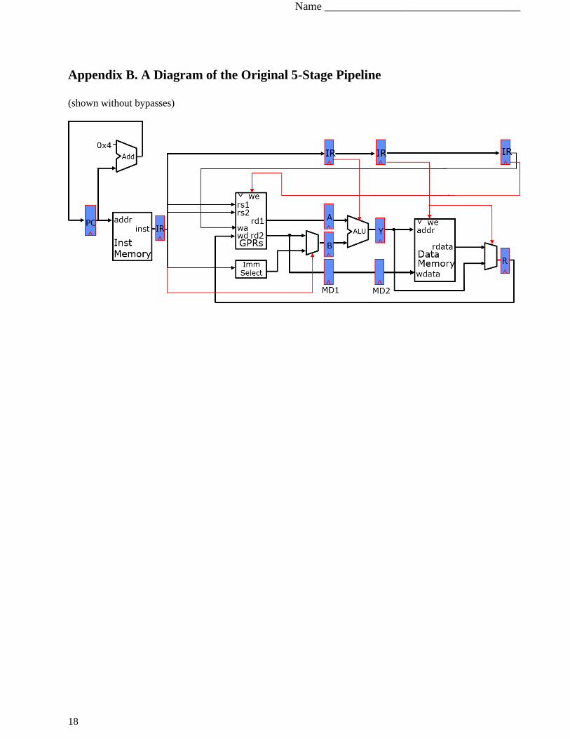
Appendix B. A Diagram of the Original 5-Stage Pipeline
(shown without bypasses)