Embed Size (px)
Citation preview
CS2302 - COMPUTER NETWORKS
UNIT - I
Computer networks
UNIT I
Network architecture – layers – Physical links – Channel Access on links – Hybrid multiple access techniques – Issues in the data link layer – Framing – Error correction and detection – Link-level flow control
UNIT II
Medium access – CSMA – Ethernet – Token ring – FDDI – Wireless LAN – Bridges and Switches
UNIT III
Circuit Switching vs Packet switching / Packet switched networks – IP – ARP – RARP – DHCP – ICMP – Queueing discipline – Routing algorithms – RIP – OSPF – Subnetting – CIDR – Interdomain routing – BGP – Ipv6 – Multicasting – Congestion avoidance in network layer
UNIT IV
UDP – TCP – Adaptive Flow Control – Adaptive Retransmission – Congestion Control – Congestion avoidance – QoS
UNIT V
Email(SMTP , MIME, IMAP, POP3) – HTTP – DNS – SNMP – Telnet – FTP – Security – PGP – SSH
TEXT BOOKS :
1. Larry L. Peterson, Bruce S. Davie, “Computer Networks: A Systems Approach”, Third Edition, Morgan Kauffmann Publishers Inc., 2003.
REFERENCES:
1. James F. Kuross, Keith W. Ross, “Computer Networking, A Top-Down Approach Featuring the Internet”, Third Edition, Addison Wesley, 2004.
2. Nader F. Mir, “Computer and Communication Networks”, Pearson Education, 2007
3. Comer, “Computer Networks and Internets with Internet Applications”, Fourth Edition, Pearson Education, 2003.
4. Andrew S. Tannenbaum, “Computer Networks”, Fourth Edition, 2003.
5. William Stallings, “Data and Computer Communication”, Sixth Edition, Pearson Education, 2000
Unit I 1
Computer networks
UNIT I
Network architecture – layers – Physical links – Channel Access on links – Hybrid multiple access techniques – Issues in the data link layer – Framing – Error correction and detection – Link-level flow control
Introduction
Computer Network: Definition
Collection of autonomous computers interconnected by single technology.Connectivity
Connectivity occurs between two computers through physical medium like coaxial cable or an optical fiber.
Physical Medium – LinkComputers - Nodes
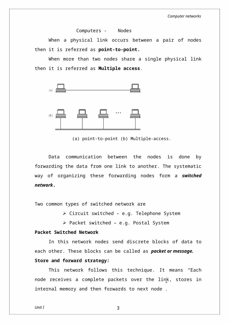
When a physical link occurs between a pair of nodes then it is referred as point-to-point.
When more than two nodes share a single physical link then it is referred as Multiple access.
(a) point-to-point (b) Multiple-access. Data communication between the nodes is done by forwarding
the data from one link to another. The systematic way of organizing these forwarding nodes form a switched network.
Unit I 2
Computer networks
Two common types of switched network are Circuit switched – e.g. Telephone System Packet switched – e.g. Postal System
Packet Switched NetworkIn this network nodes send discrete blocks of data to each other.
These blocks can be called as packet or message. Store and forward strategy:
This network follows this technique. It means “Each node receives a complete packets over the link, stores in internal memory and then forwards to next node”.Circuit Switched Network
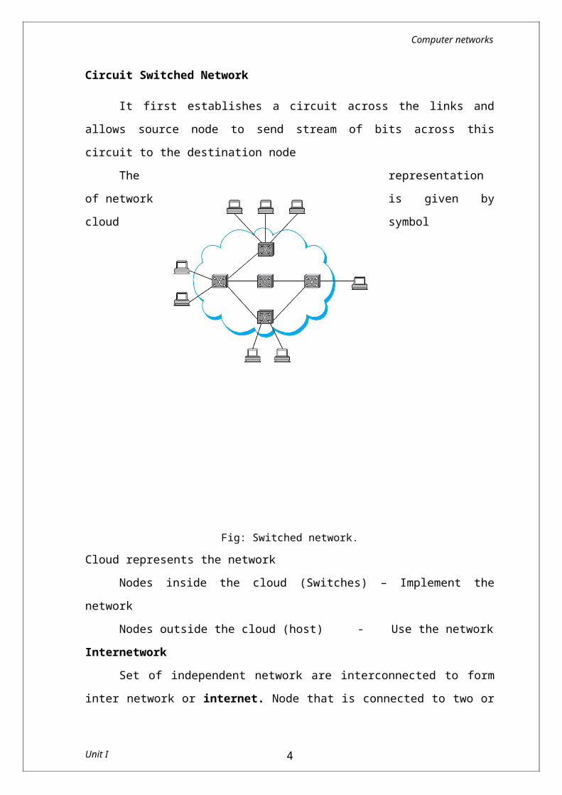
It first establishes a circuit across the links and allows source node to send stream of bits across this circuit to the destination node
The representation of network is given by cloud symbol
Fig: Switched network.Cloud represents the network
Nodes inside the cloud (Switches) – Implement the networkNodes outside the cloud (host) - Use the network
Internetwork
Unit I 3
Computer networks
Set of independent network are interconnected to form inter network or internet. Node that is connected to two or more network is called router or gateway. It is responsible for forwarding data between the networks.Addressing
The final requirement is that each node must be able to say which of the other node it wants to communicate with.
This is done by assigning address to each node. when a source node wants to deliver message to destination node, it specifies the address of destination node.
Switches and Routers use this address to decide how to forward the message. This process based on address is called Routing.
Unicast – sending message to single node.Broadcast – Sending message to all the nodes on the network.Multicast – Sending message to some subnet not to all.
Resource SharingPblm: How do several hosts share the same link when they all
want to use it at the same time?Sol: Multiplexing – System resources are shared among multiple users Methods:
1. Synchronous Time Division Multiplexing(STDM)Divide time into equal sized quanta
2. Frequency Division Multiplexing(FDM)Transmit each flow at different frequency
3. Statistical MultiplexingFirst two methods are limited in 2 ways
If one flow does not have data to send then its time quantum remains idle, even the other flow has data to transmit.
No of flows are fixed and known ahead of time, it cannot be resized.
Statistical methods combine the ideas of both STDM and FDM
Unit I 4
Computer networks
Data from each flow is transmitted on demand so no idle quantum
It defines upper bound on size of data and it is referred as packet.
Common communication patternsCommunication between a pair of processes is done by
request / reply basis. The process which sends request is referred as client and the one which honors the request is referred as server.
This can be done using channels. Two types of channels are Request / Reply channels Message stream Channels
ReliabilityTo get the reliable network, it is necessary to find how network
fails.Three classes of failures
Bit error Packet loss Physical link and node failure
Network ArchitectureNetworks do not remain fixed at single point in time, but it must
evolve to accommodate changes based on the technologies on which they are based and demands made by application programmer.
Network architecture guides the design and implementation of network. Two commonly used architecture are
OSI Architecture Internet or TCP/IP architecture
Layering and ProtocolsWhen the system gets complex, the system designer introduces
another level of abstraction. It defines unifying model with important aspects of the system, encapsulated this model in interface objects and hide it from users
In network, abstraction leads to layering. Layering provides two nice features.
Unit I 5
Computer networks
It decomposes the problem of building a network into more manageable components. Rather than implementing a monolithic piece of software that does everything implement several layers, each of which solves one part of the problem.
It provides more modular design. To add some new service, it is enough to modify the functionality at one layer, reusing the functions provided at all the other layers.
ProtocolsA protocol is a set of rules that governs data communication. It
defines what is communicated, how it is communicated, and when it is communicated. The key elements of a protocol are syntax, semantics and timing.
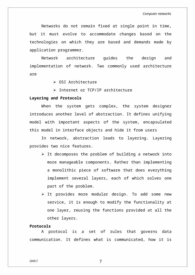
Each protocol defines two different interfaces. Service interface - to the other objects on the same
computer that want to use its communication services. This service interface defines the operations that local objects can perform on the protocol.
Peer interface - to its counterpart (peer) on another machine. It also defines the form and meaning of messages exchanged between protocol peers to implement the communication service.
Fig: Service and peer interfaces.
Except at the hardware level, peer to peer communication is indirect.
Unit I 6
Computer networks
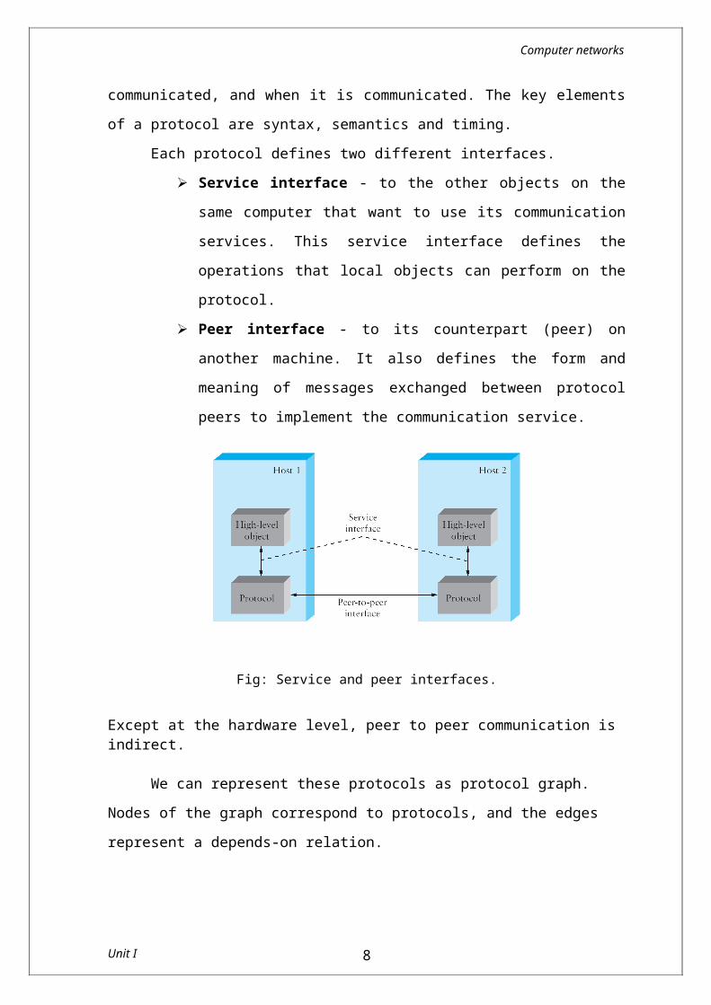
We can represent these protocols as protocol graph. Nodes of the graph correspond to protocols, and the edges represent a depends-on relation.
Fig: Example of a protocol graph.
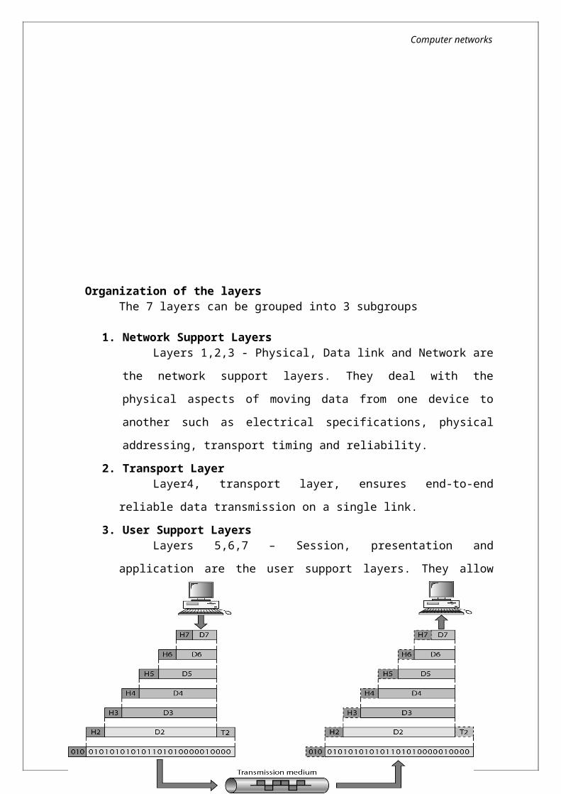
For example, the file access program on host 1 wants to send a message to its peer on host 2 using the communication service offered by protocol RRP. In this case, the file application asks RRP to send the message on its behalf. To communicate with its peer, RRP then invokes the services of HHP, which in turn transmits the message to its peer on the other machine. Once the message has arrived at protocol HHP on host 2, HHP passes the message up to RRP, which in turn delivers the message to the file application. In this particular case, the application is said to employ the services of the protocol stack RRP/HHP.Encapsulation
Control information must be added with the data to instruct the peer how to handle with the received message. It will be added into the header or trailer.
Unit I 7
Computer networks
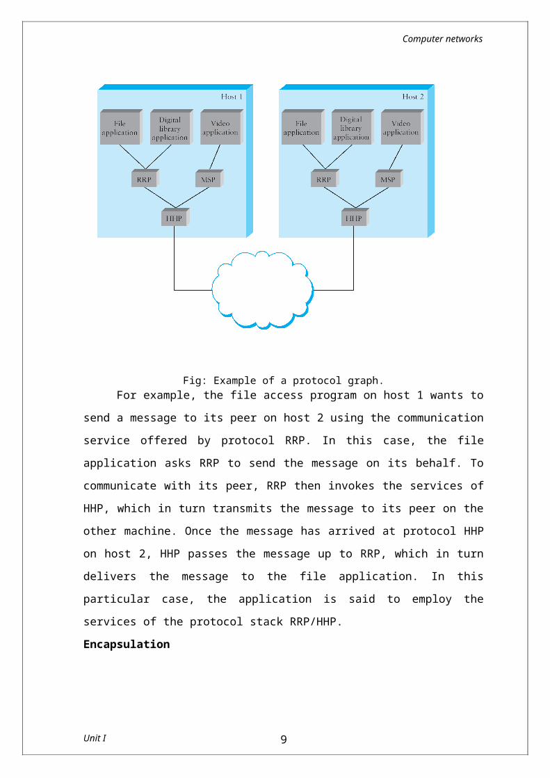
Header - Small data structure from few bytes to few kilobytes attached to the front of message.
Trailer – Information will be added at the end of the messagePayload or message body – Data send by the programIn this case data is encapsulated with new message created by protocol at each level.
Fig: High-level messages are encapsulated inside of low-level messages.
In this example HHP encapsulates RRP’s message by attaching a header of its own. Then HHP sends the message to its peer over some network, and then when the message arrives at the destination host, it is processed in the opposite order.
Multiplexing and De-MultiplexingThe fundamental idea of packet switching is to multiplex multiple
flows of data over a single physical link. This can be achieved by adding identifier to the header message. It is known as
Unit I 8
Computer networks
demultiplexing or demux key. It gives the address to which it has to communicate.
The messages are demultiplexed at the destination side. In some cases same demux key is used on both sides and in some cases different keys are used.
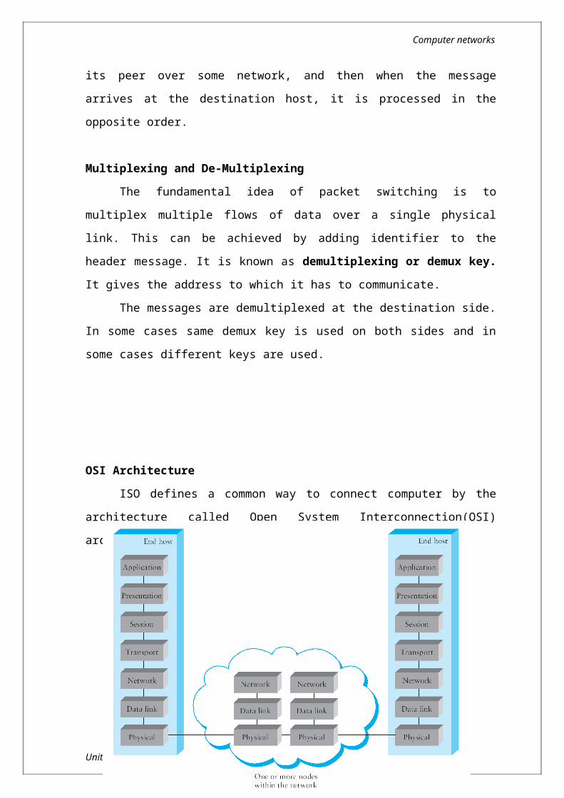
OSI ArchitectureISO defines a common way to connect computer by the
architecture called Open System Interconnection(OSI) architecture.Network functionality is divided into seven layers.
Organization of the layersThe 7 layers can be grouped into 3 subgroups
1. Network Support LayersLayers 1,2,3 - Physical, Data link and Network are the
network support layers. They deal with the physical aspects of
Unit I 9
Computer networks
moving data from one device to another such as electrical specifications, physical addressing, transport timing and reliability.
2. Transport LayerLayer4, transport layer, ensures end-to-end reliable data
transmission on a single link.3. User Support Layers
Layers 5,6,7 – Session, presentation and application are the user support layers. They allow interoperability among unrelated software systems
An Data exchange using the OSI model
Functions of the Layers
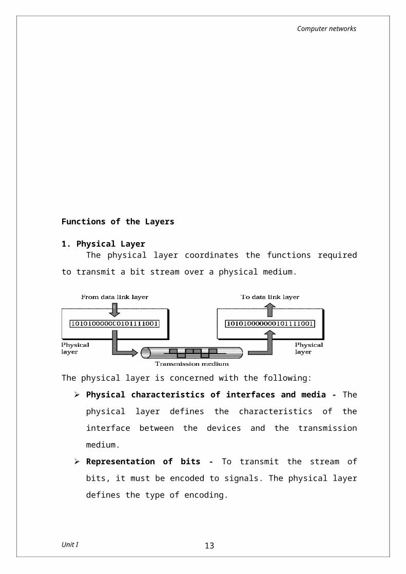
1. Physical LayerThe physical layer coordinates the functions required to transmit
a bit stream over a physical medium.
Unit I 10
Computer networks
The physical layer is concerned with the following: Physical characteristics of interfaces and media - The
physical layer defines the characteristics of the interface between the devices and the transmission medium.
Representation of bits - To transmit the stream of bits, it must be encoded to signals. The physical layer defines the type of encoding.
Data Rate or Transmission rate - The number of bits sent each second – is also defined by the physical layer.
Synchronization of bits - The sender and receiver must be synchronized at the bit level. Their clocks must be synchronized.
Line Configuration - In a point-to-point configuration, two devices are connected together through a dedicated link. In a multipoint configuration, a link is shared between several devices.
Physical Topology - The physical topology defines how devices are connected to make a network. Devices can be connected using a mesh, bus, star or ring topology.
Transmission Mode - The physical layer also defines the direction of transmission between two devices: simplex, half-duplex or full-duplex.
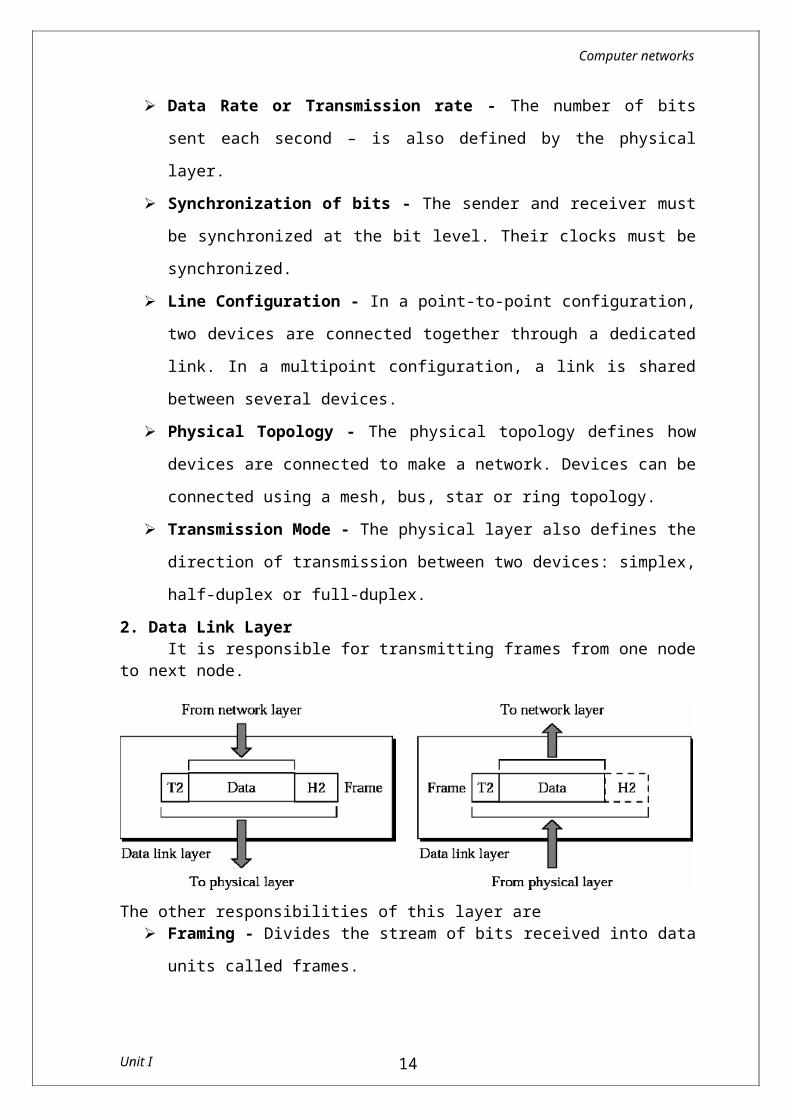
2. Data Link LayerIt is responsible for transmitting frames from one node to next
node.
Unit I 11
Computer networks
The other responsibilities of this layer are Framing - Divides the stream of bits received into data units
called frames. Physical addressing – If frames are to be distributed to
different systems on the n/w , data link layer adds a header to the frame to define the sender and receiver.
Flow control- If the rate at which the data are absorbed by the receiver is less than the rate produced in the sender ,the Data link layer imposes a flow ctrl mechanism.
Error control- Used for detecting and retransmitting damaged or lost frames and to prevent duplication of frames. This is achieved through a trailer added at the end of the frame.
Access control -Used to determine which device has control over the link at any given time.
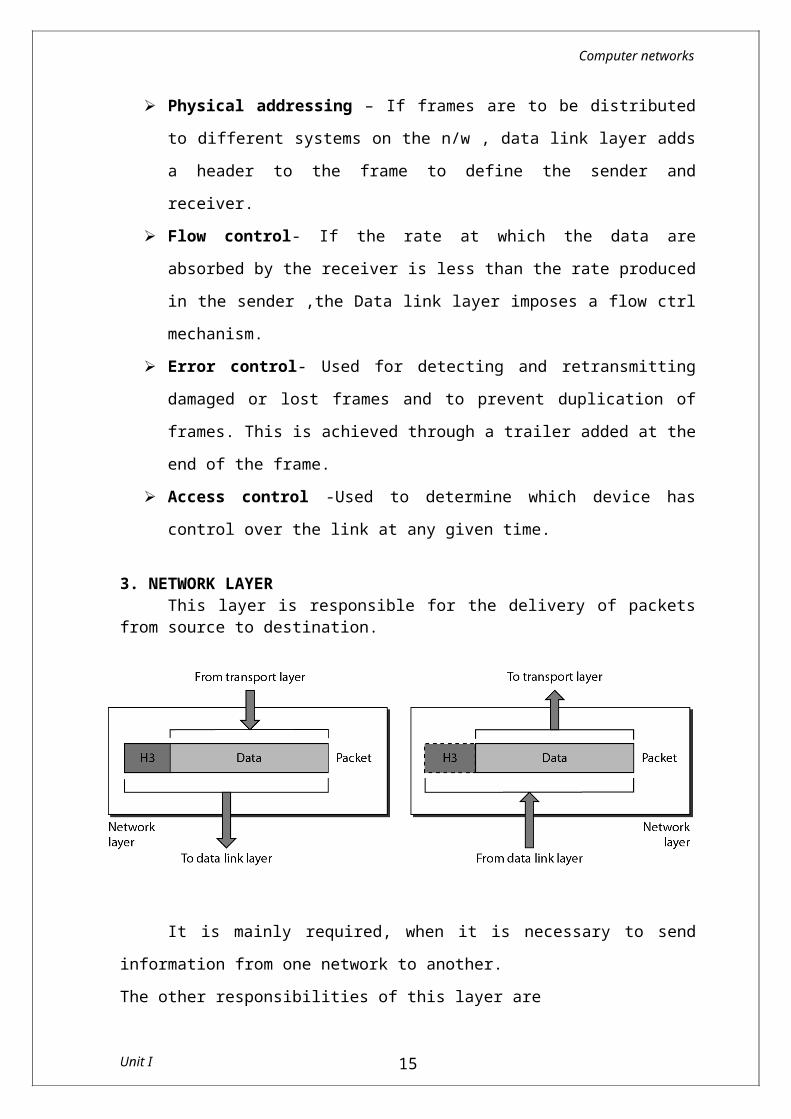
3. NETWORK LAYERThis layer is responsible for the delivery of packets from source
to destination.
Unit I 12
Computer networks
It is mainly required, when it is necessary to send information from one network to another.The other responsibilities of this layer are
Logical addressing - If a packet passes the n/w boundary, we need another addressing system for source and destination called logical address.
Routing – The devices which connects various networks called routers are responsible for delivering packets to final destination.
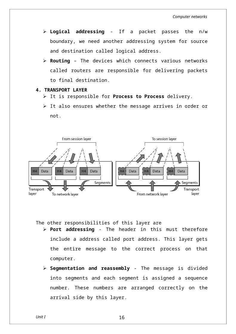
4. TRANSPORT LAYER It is responsible for Process to Process delivery. It also ensures whether the message arrives in order or not.
The other responsibilities of this layer are Port addressing - The header in this must therefore include a
address called port address. This layer gets the entire message to the correct process on that computer.
Segmentation and reassembly - The message is divided into segments and each segment is assigned a sequence number. These numbers are arranged correctly on the arrival side by this layer.
Connection control - This can either be connectionless or connection-oriented. The connectionless treats each segment as a individual packet and delivers to the destination. The connection-oriented makes connection on the destination side
Unit I 13
Computer networks
before the delivery. After the delivery the termination will be terminated.
Flow and error control - Similar to data link layer, but process to process take place.
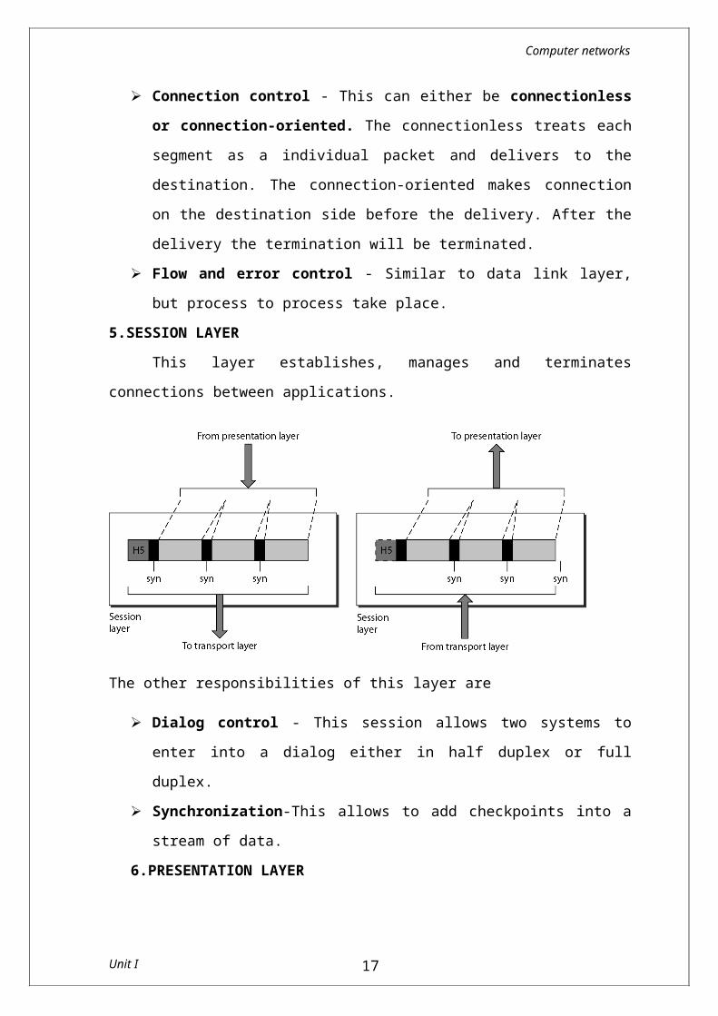
5.SESSION LAYER This layer establishes, manages and terminates connections
between applications.
The other responsibilities of this layer are
Dialog control - This session allows two systems to enter into a dialog either in half duplex or full duplex.
Synchronization-This allows to add checkpoints into a stream of data.
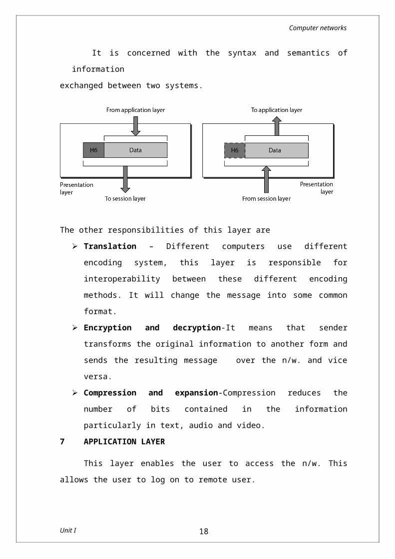
6.PRESENTATION LAYER
It is concerned with the syntax and semantics of information exchanged between two systems.
Unit I 14
Computer networks
The other responsibilities of this layer are Translation – Different computers use different encoding
system, this layer is responsible for interoperability between these different encoding methods. It will change the message into some common format.
Encryption and decryption-It means that sender transforms the original information to another form and sends the resulting message over the n/w. and vice versa.
Compression and expansion-Compression reduces the number of bits contained in the information particularly in text, audio and video.
7 APPLICATION LAYER
This layer enables the user to access the n/w. This allows the user to log on to remote user.
The other
responsibilities of this layer are
Unit I 15
Computer networks
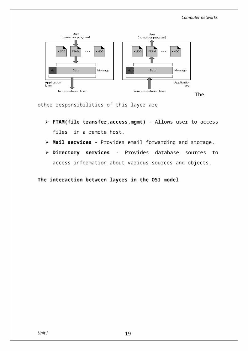
FTAM(file transfer,access,mgmt) - Allows user to access files in a remote host.
Mail services - Provides email forwarding and storage. Directory services - Provides database sources to access
information about various sources and objects.
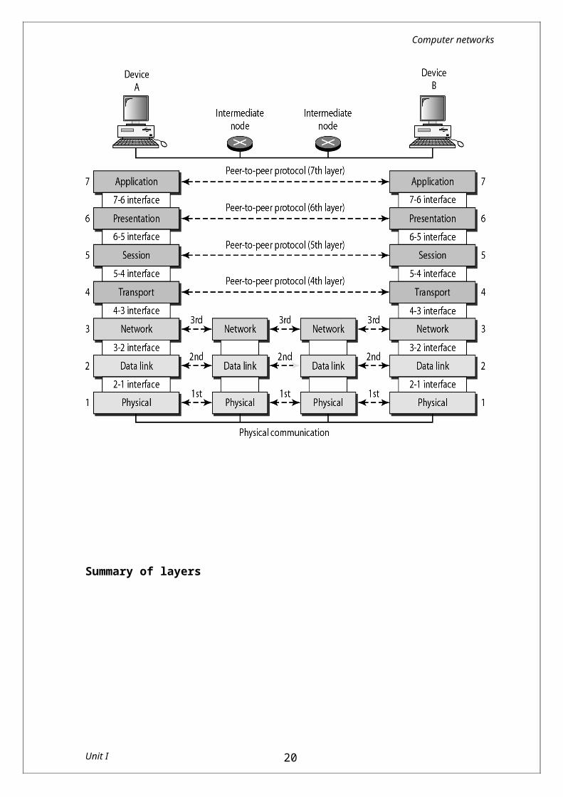
The interaction between layers in the OSI model
Summary of layers
Unit I 16
Computer networks
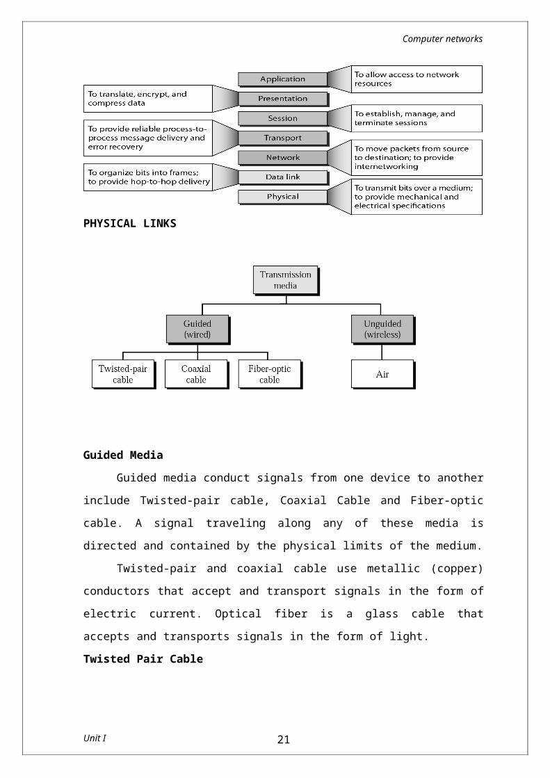
PHYSICAL LINKS
Guided Media Guided media conduct signals from one device to another include
Twisted-pair cable, Coaxial Cable and Fiber-optic cable. A signal traveling along any of these media is directed and contained by the physical limits of the medium.
Twisted-pair and coaxial cable use metallic (copper) conductors that accept and transport signals in the form of electric current. Optical fiber is a glass cable that accepts and transports signals in the form of light.Twisted Pair Cable
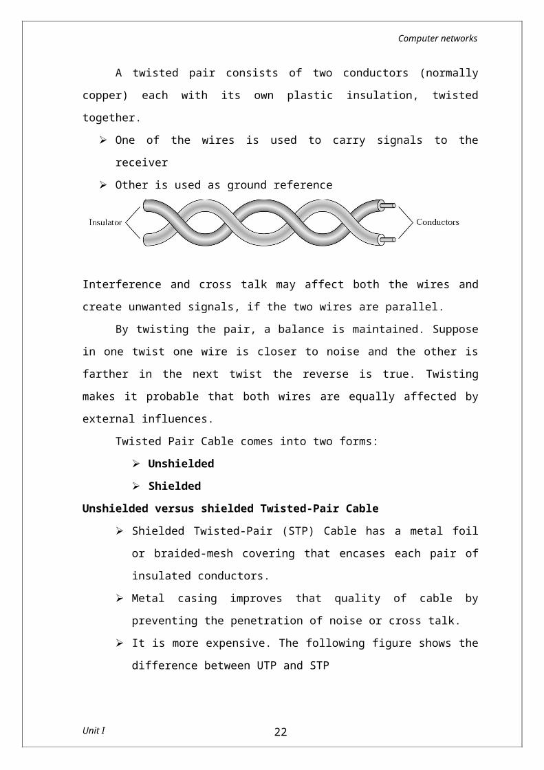
A twisted pair consists of two conductors (normally copper) each with its own plastic insulation, twisted together.
One of the wires is used to carry signals to the receiver Other is used as ground reference
Unit I 17
Computer networks
Interference and cross talk may affect both the wires and create unwanted signals, if the two wires are parallel.
By twisting the pair, a balance is maintained. Suppose in one twist one wire is closer to noise and the other is farther in the next twist the reverse is true. Twisting makes it probable that both wires are equally affected by external influences.
Twisted Pair Cable comes into two forms: Unshielded Shielded
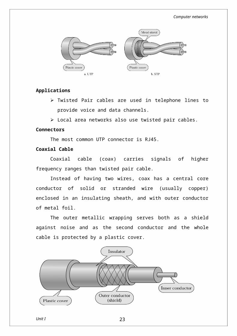
Unshielded versus shielded Twisted-Pair Cable Shielded Twisted-Pair (STP) Cable has a metal foil or braided-
mesh covering that encases each pair of insulated conductors. Metal casing improves that quality of cable by preventing the
penetration of noise or cross talk. It is more expensive. The following figure shows the difference
between UTP and STP
Applications Twisted Pair cables are used in telephone lines to provide
voice and data channels. Local area networks also use twisted pair cables.
ConnectorsThe most common UTP connector is RJ45.
Unit I 18
Computer networks
Coaxial CableCoaxial cable (coax) carries signals of higher frequency ranges
than twisted pair cable.Instead of having two wires, coax has a central core conductor of
solid or stranded wire (usually copper) enclosed in an insulating sheath, and with outer conductor of metal foil.
The outer metallic wrapping serves both as a shield against noise and as the second conductor and the whole cable is protected by a plastic cover.
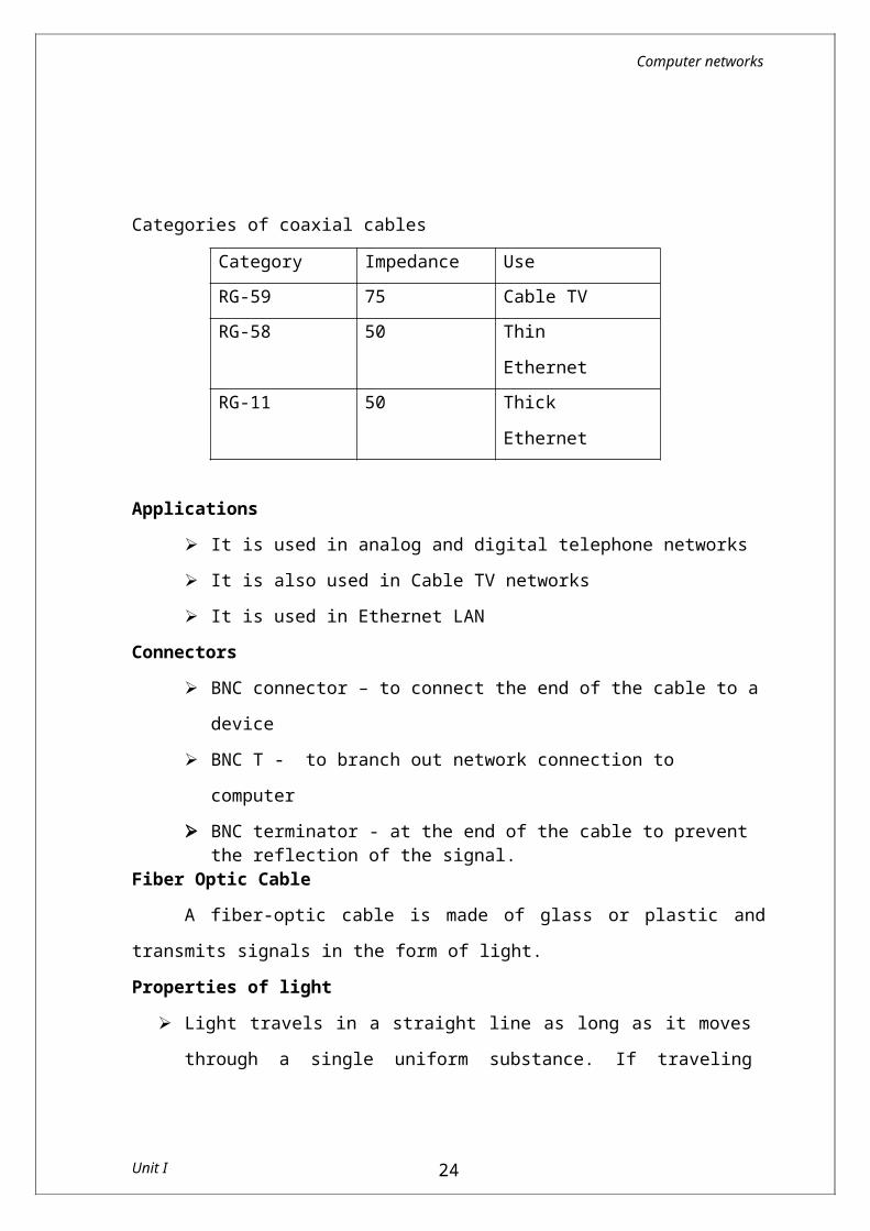
Categories of coaxial cables
Category Impedance UseRG-59 75 Cable TV RG-58 50 Thin EthernetRG-11 50 Thick Ethernet
Applications It is used in analog and digital telephone networks It is also used in Cable TV networks It is used in Ethernet LAN
Connectors BNC connector – to connect the end of the cable to a device BNC T - to branch out network connection to computer BNC terminator - at the end of the cable to prevent the
reflection of the signal.
Unit I 19
Computer networks
Fiber Optic CableA fiber-optic cable is made of glass or plastic and transmits
signals in the form of light.Properties of light
Light travels in a straight line as long as it moves through a single uniform substance. If traveling through one substance suddenly enters another, ray changes its direction.
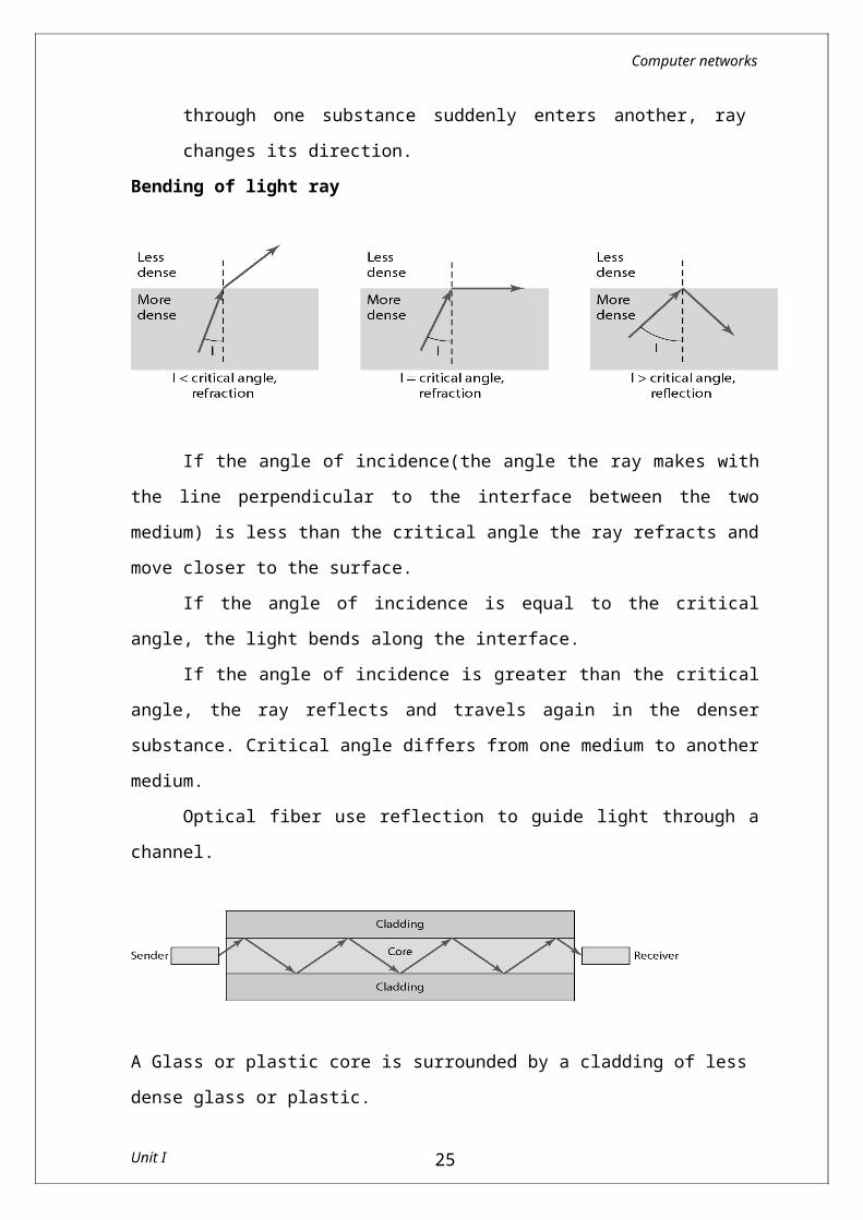
Bending of light ray
If the angle of incidence(the angle the ray makes with the line perpendicular to the interface between the two medium) is less than the critical angle the ray refracts and move closer to the surface.
If the angle of incidence is equal to the critical angle, the light bends along the interface.
If the angle of incidence is greater than the critical angle, the ray reflects and travels again in the denser substance. Critical angle differs from one medium to another medium.
Optical fiber use reflection to guide light through a channel.
A Glass or plastic core is surrounded by a cladding of less dense glass or plastic.
Unit I 20
Computer networks
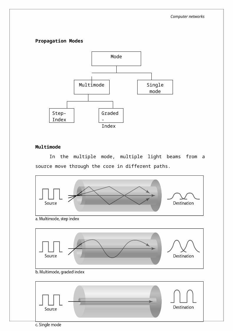
Propagation Modes
MultimodeIn the multiple mode, multiple light beams from a source move
through the core in different paths.
Unit I 21
Mode
Step-Index
Multimode Single mode
Graded - Index
Computer networks
Multimode-Step-Index fiber: The density of core remains constant from the centre to the edge.
A ray of light moves through this constant density in a straight line until it reaches the interface of the core and the cladding. At the interface there is an abrupt change to a lower density that changes the angle of the beam’s motion.
Multimode- Graded -Index fiber: The density is varying. Density is highest at the centre of the core and decreases gradually to its lowest at the edge.
Single ModeSingle mode uses step-index fiber and a highly focused source of light
that limits beams to a small range of angles, all close to the horizontal.The single mode fiber itself is manufactured with a much smaller
diameter than that of multimedia fiber.Connectors
Subscriber channel (SC) connector is used for cable TV. Straight-tip (ST) connector is used for connecting cable to
networking devices.
Advantages of Optical Fiber Noise resistance Less signal attenuation Light weight
Disadvantages Cost Installation and maintenance Unidirectional Fragility (easily broken)
Unguided mediaUnguided media transport electromagnetic waves without using
a physical conductor. This type of communication is often referred to as wireless communication.
Unit I 22
Computer networks
Signals are normally broadcast through air and thus available to anyone who has device capable of receiving them.
Unguided signals can travel from the source to destination in several ways:
Ground propagation – waves travel through lowest portion on
atmosphere. Sky propagation – High frequency waves radiate upward
into ionosphere and reflected back to earth.
Line-of-sight propagation – Very high frequency signals travel
in a straight line
Radio WavesElectromagnetic waves ranging in frequencies between 3 kHz and 1 GHz are normally called radio waves.
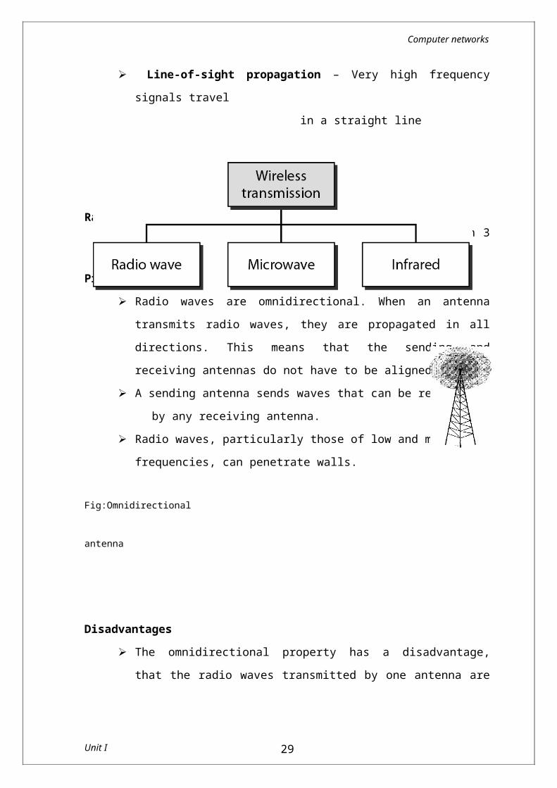
Properties Radio waves are omnidirectional. When an antenna transmits
radio waves, they are propagated in all directions. This means that the sending and receiving antennas do not have to be aligned.
A sending antenna sends waves that can be received by any receiving antenna. Radio waves, particularly those of low and medium
frequencies, can penetrate walls. Fig:Omnidirectional antenna
Unit I 23
Computer networks
Disadvantages The omnidirectional property has a disadvantage, that the
radio waves transmitted by one antenna are susceptible to interference by another antenna that may send signals using the same frequency or band.
As Radio waves can penetrate through walls, we cannot isolate a communication to just inside or outside a building.
ApplicationsRadio waves are used for multicast communications, such as
radio and television, and paging systems.
MicrowavesElectromagnetic waves having frequencies between 1 and 300
GHz are called microwaves.Properties
Microwaves are unidirectional. Sending and receiving antennas need to be aligned Microwave propagation is line-of-sight Very high-frequency microwaves cannot penetrate walls
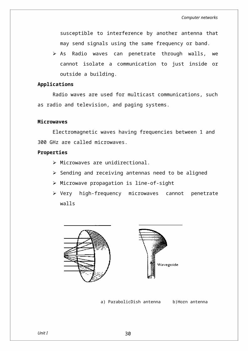
a) ParabolicDish antenna b)Horn antenna
Parabolic Dish antenna focus all incoming waves into single point
Outgoing transmissions are broadcast through a horn aimed at the dish.
Unit I 24
Computer networks
Disadvantage If receivers are inside buildings, they cannot receive these
wavesApplications
Microwaves are used for unicast communication such as cellular telephones, satellite networks, and wireless LANs.
Infrared Electromagnetic waves with frequencies from 300 GHz to 400
THz are called infrared rays Infrared waves, having high frequencies, cannot penetrate
walls.Applications
Infrared signals can be used for short-range communication in a closed area using line-of-sight propagation.
Channel Access on linksMultiple Access Techniques Various multiple access techniques are
Frequency Division Multiple Access(FDMA) Time Division Multiple Access (TDMA) Code Division Multiple Access(CDMA)
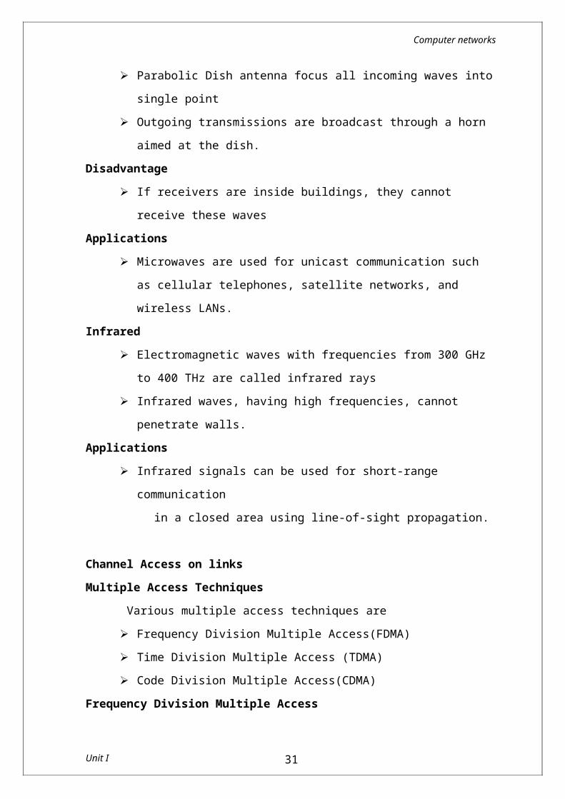
Frequency Division Multiple Access In frequency-division multiple access (FDMA), the available
bandwidth is divided into frequency bands. Each station is allocated a band to send its data. In this method when any one frequency level is kept idle and
another is used frequently leads to inefficiency.
Unit I 25
f f5 f4 f3 f2 f1
T
Computer networks
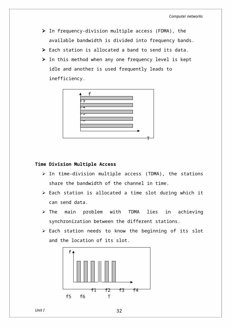
Time Division Multiple Access In time-division multiple access (TDMA), the stations share the
bandwidth of the channel in time. Each station is allocated a time slot during which it can send
data. The main problem with TDMA lies in achieving synchronization
between the different stations. Each station needs to know the beginning of its slot and the
location of its slot.
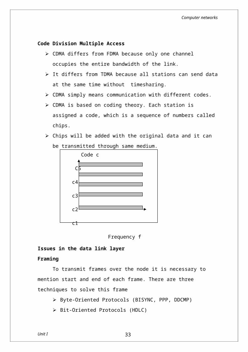
Code Division Multiple Access CDMA differs from FDMA because only one channel occupies the
entire bandwidth of the link. It differs from TDMA because all stations can send data at the
same time without timesharing. CDMA simply means communication with different codes. CDMA is based on coding theory. Each station is assigned a code,
which is a sequence of numbers called chips. Chips will be added with the original data and it can be
transmitted through same medium.
Unit I 26
f
f1 f2 f3 f4 f5 f6 T
Code c
C5
c4
c3
c2
c1
Frequency f
Computer networks
Issues in the data link layer Framing
To transmit frames over the node it is necessary to mention start and end of each frame. There are three techniques to solve this frame
Byte-Oriented Protocols (BISYNC, PPP, DDCMP) Bit-Oriented Protocols (HDLC) Clock-Based Framing (SONET)
Byte Oriented protocols In this, view each frame as a collection of bytes (characters) rather than a collection of bits. Such a byte-oriented approach is exemplified by the BISYNC (Binary Synchronous Communication) protocol and the DDCMP (Digital Data Communication Message Protocol) Sentinel Approach
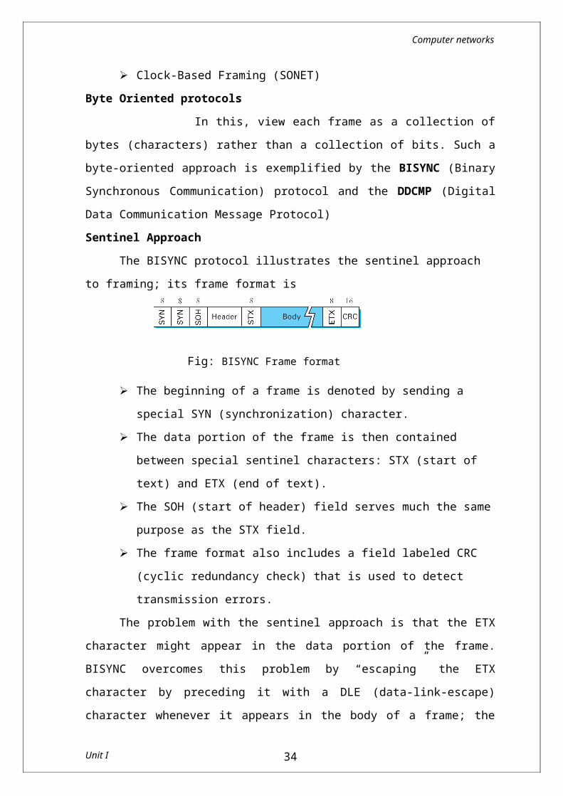
The BISYNC protocol illustrates the sentinel approach to framing; its frame format is
Fig: BISYNC Frame format
The beginning of a frame is denoted by sending a special SYN (synchronization) character.
The data portion of the frame is then contained between special sentinel characters: STX (start of text) and ETX (end of text).
The SOH (start of header) field serves much the same purpose as the STX field.
The frame format also includes a field labeled CRC (cyclic redundancy check) that is used to detect transmission errors.
Unit I 27
Computer networks
The problem with the sentinel approach is that the ETX character might appear in the data portion of the frame. BISYNC overcomes this problem by “escaping” the ETX character by preceding it with a DLE (data-link-escape) character whenever it appears in the body of a frame; the DLE character is also escaped (by preceding it with an extra DLE) in the frame body. This approach is called character stuffing.
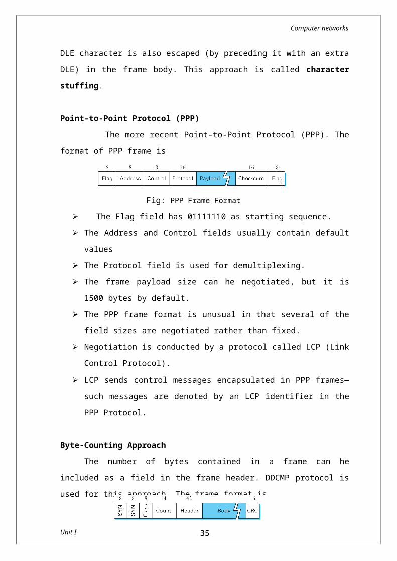
Point-to-Point Protocol (PPP)The more recent Point-to-Point Protocol (PPP). The format of
PPP frame is
Fig: PPP Frame Format The Flag field has 01111110 as starting sequence. The Address and Control fields usually contain default values The Protocol field is used for demultiplexing. The frame payload size can he negotiated, but it is 1500 bytes by
default. The PPP frame format is unusual in that several of the field sizes
are negotiated rather than fixed. Negotiation is conducted by a protocol called LCP (Link Control
Protocol). LCP sends control messages encapsulated in PPP frames—such
messages are denoted by an LCP identifier in the PPP Protocol.
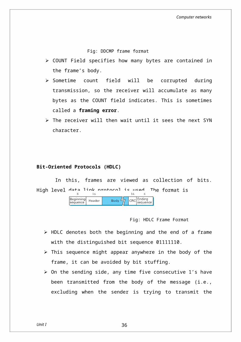
Byte-Counting ApproachThe number of bytes contained in a frame can he included as a
field in the frame header. DDCMP protocol is used for this approach. The frame format is
Fig: DDCMP frame format
Unit I 28
Computer networks
COUNT Field specifies how many bytes are contained in the frame’s body.
Sometime count field will be corrupted during transmission, so the receiver will accumulate as many bytes as the COUNT field indicates. This is sometimes called a framing error.
The receiver will then wait until it sees the next SYN character.
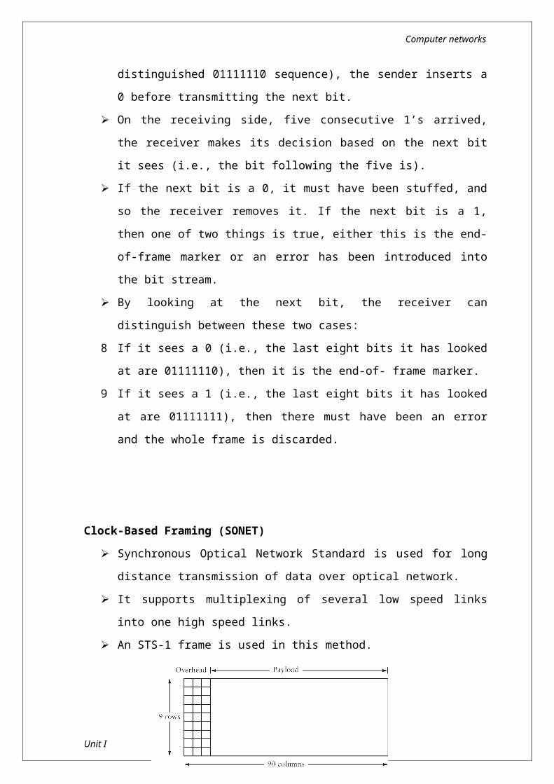
Bit-Oriented Protocols (HDLC)
In this, frames are viewed as collection of bits. High level data link protocol is used. The format is
Fig: HDLC Frame Format
HDLC denotes both the beginning and the end of a frame with the distinguished bit sequence 01111110.
This sequence might appear anywhere in the body of the frame, it can be avoided by bit stuffing.
On the sending side, any time five consecutive 1’s have been transmitted from the body of the message (i.e., excluding when the sender is trying to transmit the distinguished 01111110 sequence), the sender inserts a 0 before transmitting the next bit.
On the receiving side, five consecutive 1’s arrived, the receiver makes its decision based on the next bit it sees (i.e., the bit following the five is).
If the next bit is a 0, it must have been stuffed, and so the receiver removes it. If the next bit is a 1, then one of two things is true, either this is the end-of-frame marker or an error has been introduced into the bit stream.
By looking at the next bit, the receiver can distinguish between these two cases:
Unit I 29
Computer networks
8 If it sees a 0 (i.e., the last eight bits it has looked at are 01111110), then it is the end-of- frame marker.
9 If it sees a 1 (i.e., the last eight bits it has looked at are 01111111), then there must have been an error and the whole frame is discarded.
Clock-Based Framing (SONET) Synchronous Optical Network Standard is used for long distance
transmission of data over optical network. It supports multiplexing of several low speed links into one high
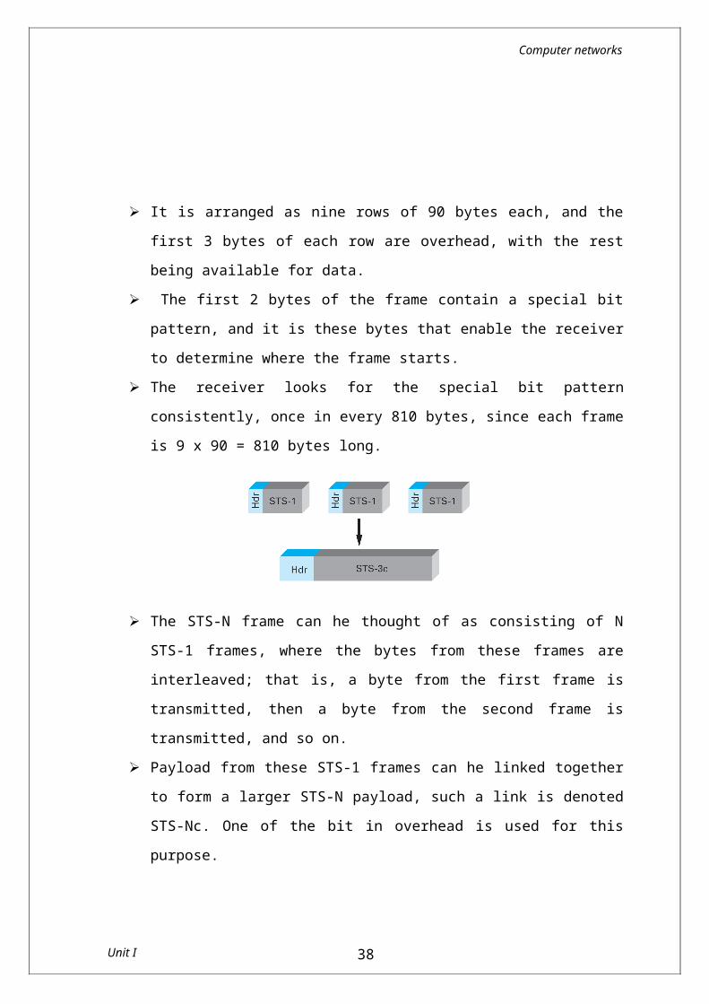
speed links. An STS-1 frame is used in this method.
It is arranged as nine rows of 90 bytes each, and the first 3 bytes of each row are overhead, with the rest being available for data.
The first 2 bytes of the frame contain a special bit pattern, and it is these bytes that enable the receiver to determine where the frame starts.
The receiver looks for the special bit pattern consistently, once in every 810 bytes, since each frame is 9 x 90 = 810 bytes long.
Unit I 30
Computer networks
The STS-N frame can he thought of as consisting of N STS-1 frames, where the bytes from these frames are interleaved; that is, a byte from the first frame is transmitted, then a byte from the second frame is transmitted, and so on.
Payload from these STS-1 frames can he linked together to form a larger STS-N payload, such a link is denoted STS-Nc. One of the bit in overhead is used for this purpose.
Error Detection and CorrectionData can be corrupted during transmission. For reliable
communication, errors must be detected and corrected.
Types of Errors
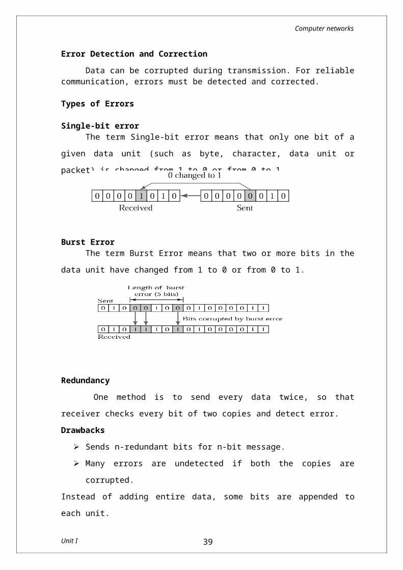
Single-bit errorThe term Single-bit error means that only one bit of a given data
unit (such as byte, character, data unit or packet) is changed from 1 to 0 or from 0 to 1.
Burst ErrorThe term Burst Error means that two or more bits in the data unit
have changed from 1 to 0 or from 0 to 1.
RedundancyOne method is to send every data twice, so that receiver
checks every bit of two copies and detect error.Drawbacks
Sends n-redundant bits for n-bit message.
Unit I 31
Computer networks
Many errors are undetected if both the copies are corrupted.Instead of adding entire data, some bits are appended to each unit.
This is called redundant bit because the bits added will not give any new information. These bits are called error detecting codes.The three error detecting techniques are:
Parity check Check sum algorithm Cyclic Redundancy Check
Parity CheckSimple parity check
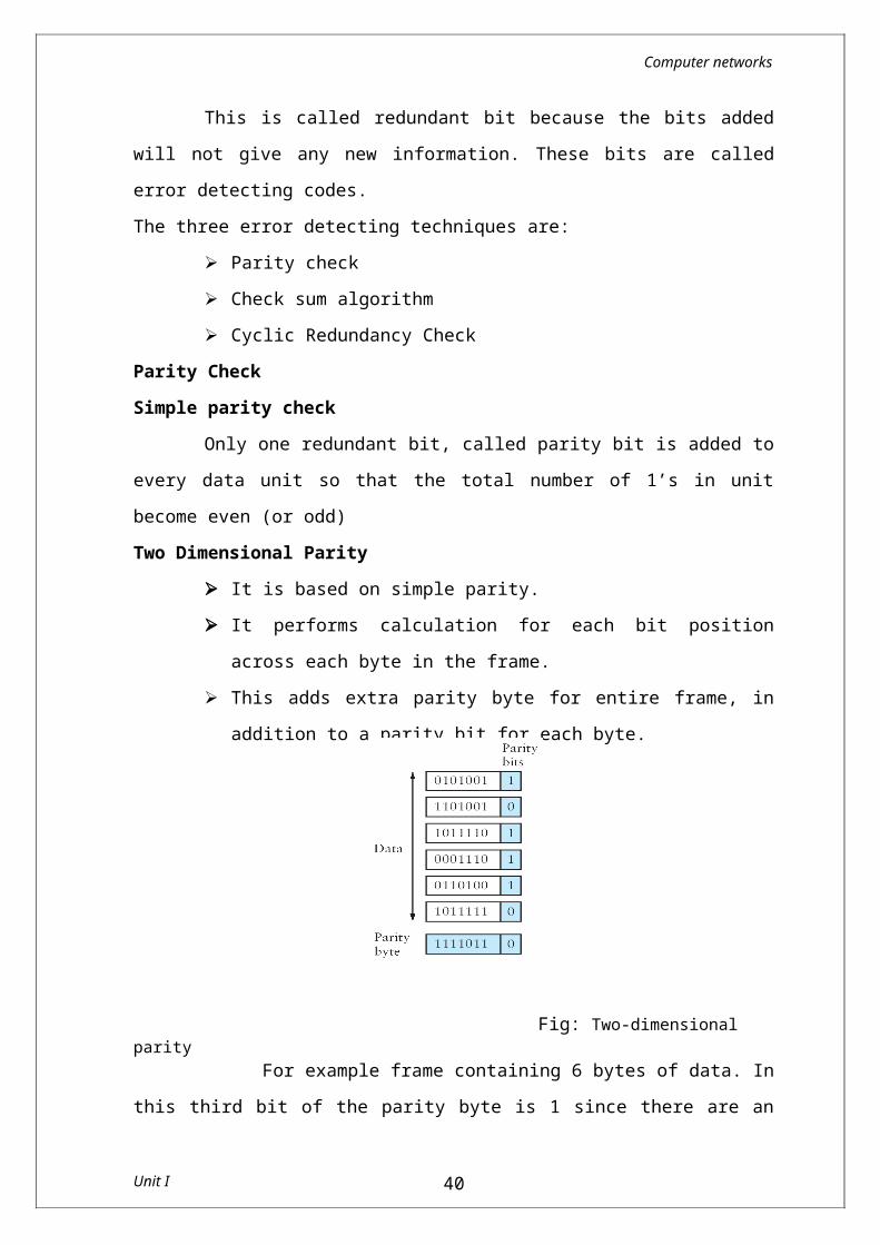
Only one redundant bit, called parity bit is added to every data unit so that the total number of 1’s in unit become even (or odd)Two Dimensional Parity
It is based on simple parity. It performs calculation for each bit position across each byte
in the frame. This adds extra parity byte for entire frame, in addition to a
parity bit for each byte.
Fig: Two-dimensional parity For example frame containing 6 bytes of data. In this third bit of the parity byte is 1 since there are an odd number of 1’s is in the third bit across the 6 bytes in the frame. In this case, 14 bits of redundant information are added with original information.
Check sum algorithm
Unit I 32
Computer networks
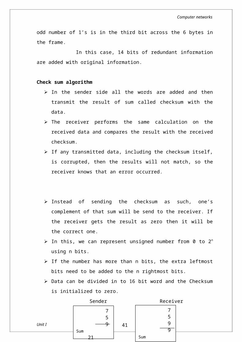
In the sender side all the words are added and then transmit the result of sum called checksum with the data.
The receiver performs the same calculation on the received data and compares the result with the received checksum.
If any transmitted data, including the checksum itself, is corrupted, then the results will not match, so the receiver knows that an error occurred.
Instead of sending the checksum as such, one’s complement of that sum will be send to the receiver. If the receiver gets the result as zero then it will be the correct one.
In this, we can represent unsigned number from 0 to 2n using n bits.
If the number has more than n bits, the extra leftmost bits need to be added to the n rightmost bits.
Data can be divided in to 16 bit word and the Checksum is initialized to zero.
Sender Receiver
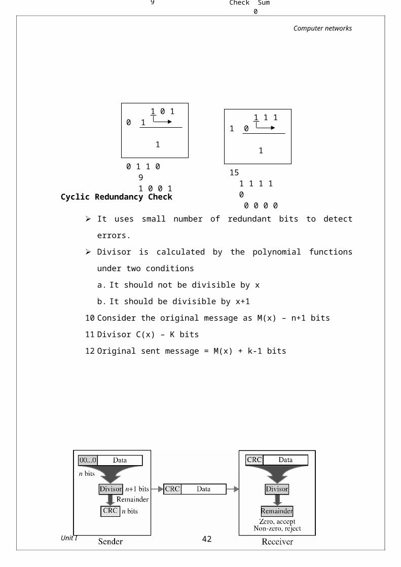
Cyclic Redundancy Check
It uses small number of redundant bits to detect errors. Divisor is calculated by the polynomial functions under two
conditionsa. It should not be divisible by x
Unit I 33
759
Sum 21Check Sum 9
1 0 1 0 1 1
0 1 1 09 1 0 0 1
1 1 1 1 0 1
15 1 1 1 1 0 0 0 0 0
7599
Sum 30Check Sum 0
Computer networks
b. It should be divisible by x+110 Consider the original message as M(x) – n+1 bits11 Divisor C(x) – K bits12 Original sent message = M(x) + k-1 bits
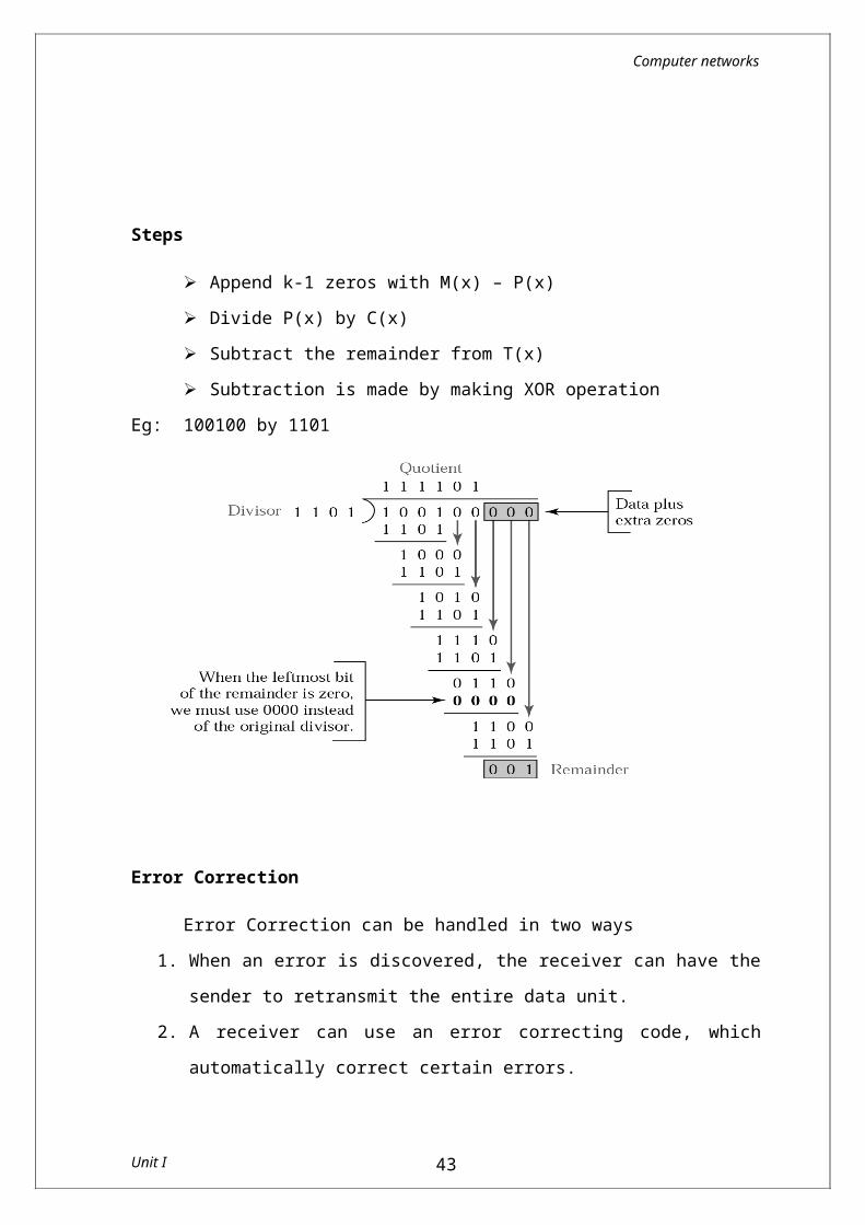
Steps
Append k-1 zeros with M(x) – P(x) Divide P(x) by C(x) Subtract the remainder from T(x) Subtraction is made by making XOR operation
Eg: 100100 by 1101
Unit I 34
Computer networks
Error Correction
Error Correction can be handled in two ways1. When an error is discovered, the receiver can have the sender to
retransmit the entire data unit.2. A receiver can use an error correcting code, which automatically
correct certain errors.
Error correcting codes are more sophisticated than error-detection codes and require more redundancy bits.
In single bit error detection only two states are sufficient.1) error2) no error
Two states are not enough to detect an error but not to correct it. Redundancy Bits
To calculate the number of redundancy bit(r) required to correct a given number of data bits (m), we must find a relationship between m and r.
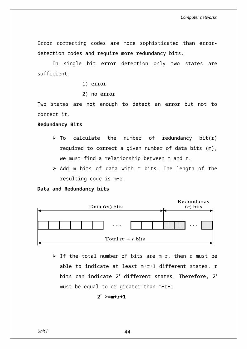
Add m bits of data with r bits. The length of the resulting code is m+r.
Data and Redundancy bits
If the total number of bits are m+r, then r must be able to indicate at least m+r+1 different states. r bits can indicate 2r
different states. Therefore, 2r must be equal to or greater than m+r+1
Unit I 35
Computer networks
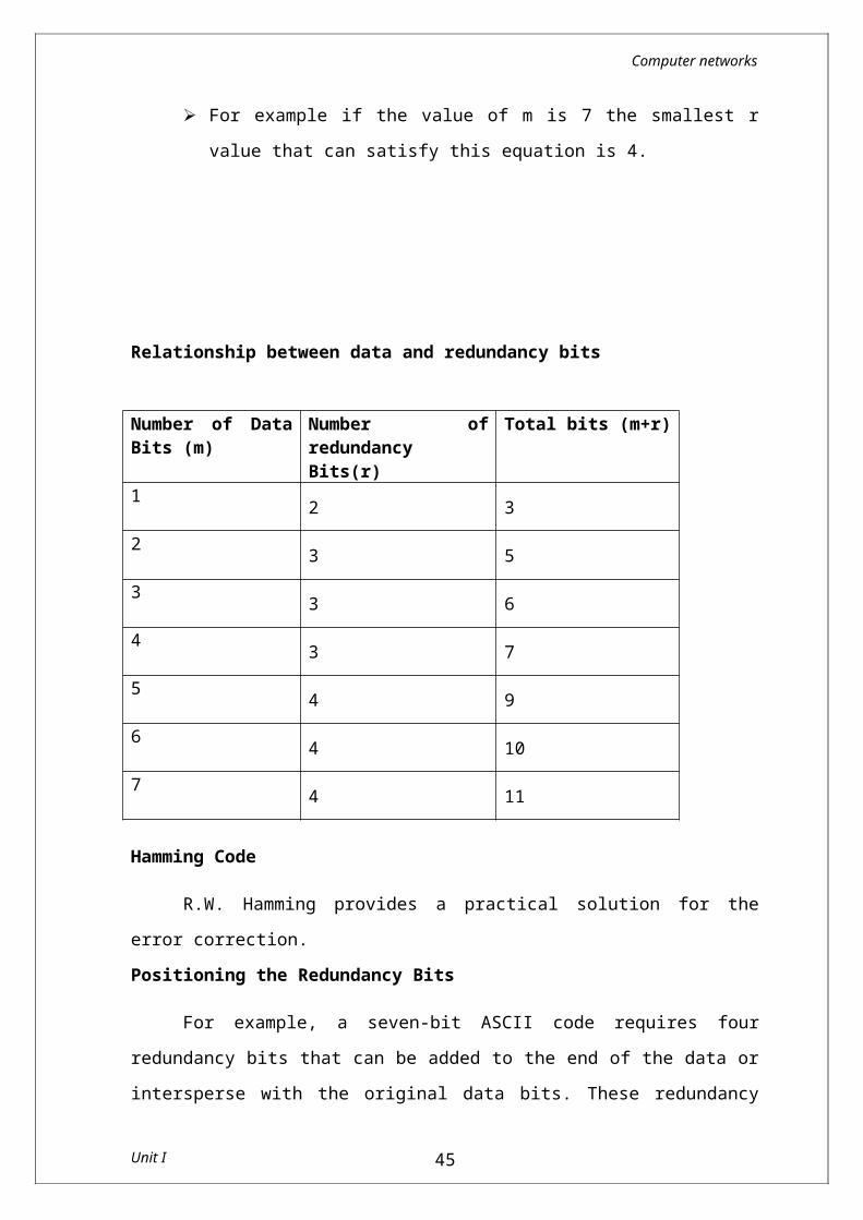
2r >=m+r+1 For example if the value of m is 7 the smallest r value that can
satisfy this equation is 4.
Relationship between data and redundancy bits
Number of Data Bits (m)
Number of redundancy Bits(r)
Total bits (m+r)
1 2 32 3 53 3 64 3 75 4 96 4 107 4 11
Hamming Code
R.W. Hamming provides a practical solution for the error correction.Positioning the Redundancy Bits
For example, a seven-bit ASCII code requires four redundancy bits that can be added to the end of the data or intersperse with the original data bits. These redundancy bits are placed in positions 1, 2, 4 and 8. We refer these bits as r1, r2, r3 and r4
Position of redundancy bits in Hamming code
Unit I 36
Computer networks
The combination used to calculate each of the four r values for a seven-bit data sequence are as follows
The r1 bit is calculated using all bits positions whose binary representation include a 1 in the rightmost position
r2 is calculated using all bit position with a 1 in the second position and so on
r1: bits 1,3,5,7,9,11r2: bits 2, 3, 6, 7, 10, 11r3: bits 4, 5, 6, 7r4: bits 8, 9, 10, 11
Redundancy bits calculation
Unit I 37
Computer networks
Calculating the r values
Place each bit of the original character in its appropriate position in the 11-bit unit.
Calculate the even parities for the various bit combination. The parity value for each combination is the value of the
corresponding r bit.
For example,
The value of r1 is calculated to provide even parity for a combination of bits 3,5,7,9 and 11.
The value of r2 is calculated to provide even parity with bits 3, 6, 7, 10 and 11.
The value of r3 is calculated to provide even parity with bits 4,5,6 and 7.
The value of r4 is calculated to provide even parity with bits 8,9,10 and 11.
Error Detection and Correction
Now imagine the received data has 7th bit changed from 1 to 0.
Single-bit error
Unit I 38
Computer networks
The receiver takes the transmission and recalculates four new data using the same set of bits used by the sender plus the relevant parity (r) bit for each set.
Error detection
Then it assembles the new parity values into a binary number in order of r position (r8,r4,r2,r1).
This step gives us the binary number 0111(7 in decimal) which is the precise location of the bit in error.
Once the bit is identified, the receiver can reverse its value and correct the error.
Unit I 39
Computer networks
Hamming DistanceOne of the central concepts in coding for error control is the idea
of the Hamming distance. The Hamming distance between two words (of the same size) is
the number of differences between the corresponding bits. The Hamming distance between two words x and y is d(x, y).
The Hamming distance can be found by applying the XOR operation on the two words and count the number of 1’s in the result.
In a set of words, the minimum Hamming distance is the smallest Hamming distance between all possible pairs. We use dmin to define the minimum Hamming distance in a coding scheme.
Link Level Flow Control
Flow control is a technique that a transmitting entity does not conquer a receiving entity with data. Two fundamental mechanisms are acknowledgement and timeouts.
After getting each frame the receiver will send ACK to sender. If the sender does not receive ACK up to reasonable amount of
time then it retransmit the original frame waiting for reasonable amount of time is called timeout.
The two flow control mechanisms are Stop and wait Flow Control Sliding Window Flow Control
Stop and Wait Algorithm After transmitting one frame, the sender waits for an
acknowledgment before transmitting the next frame. If the acknowledgment does not arrive after a certain period of
time, the sender times out and retransmit the original frame.
Unit I 40
Computer networks
a) The ACK is received before the timer expires b) The original frame is lost
c) The ACK is lost d)The timeout fires too soon
Fig: illustrates four different scenarios that result from this basic algorithm. The sending side is represented on the left, the receiving side is depicted on the right, and time flows from top to bottom.
In Fig (a) ACK is received before the timer expires, (b) and (c) show the situation in which the original frame and the ACK, respectively, are lost, and (d) shows the situation in which the timeout fires too soon..
Suppose the sender sends a frame and the receiver acknowledges it, but the acknowledgment is either lost or delayed in arriving. This situation is in (c) and (d). In both cases, the sender times out and retransmit the original frame, but the receiver will think that it is the next frame, since it correctly received and acknowledged the first frame.
This makes the receiver to receive the duplicate copies. To avoid this two sequence numbers (0 and 1) must be used alternatively.
Unit I 41
Computer networks
The main drawback of the stop-and-wait algorithm is that it allows the sender have only one outstanding frame on the link at a time.
Sliding Window Algorithm The sender can transmit several frames before needing an
acknowledgement. Frames can be sent one right after another meaning that the link
can carry several frames at once and it s capacity can be used efficiently.
The receiver acknowledges only some of the frames, using a single ACK to confirm the receipt of multiple data frames
Sliding Window refers to imaginary boxes at both the sender and the receiver.
Window can hold frames at either end and provides the upper limit on the number of frames that can be transmitted before requiring an acknowledgement.
Frames are numbered modulo-n which means they are numbered from o to n-1
For eg. If n=8 the frames are numbered 0,1,2,3,4,5,6,7. i.e the size of the window is n -1.
When the receiver sends ACK it includes the number of the next frame it expects to receive.
When the sender sees an ACK with the number 5, it knows that all frames up through number 4 have been received.
There are two methods to retransmit the lost frames GO-Back N
Unit I 42
Computer networks
Selective RepeatGo – Back N Method
Sender Window
At the beginning of transmission, the sender window contains n-1 frames. As frames are sent out, the left boundary of the window moves inward, shrinking the size of the window
If size of window is W if three frames have been transmitted since the last acknowledgement then the number of frames left in the window is w -3.
Once an ACK arrives, the window expands to allow in a number of new frames equal to the number of frames acknowledged by that ACK.
Receiver Window The receive window is an abstract concept defining an imaginary
box of size 1 with one single variable Rn. The window slides when a correct frame has arrived, sliding
occurs one slot at a time.
Unit I 43
Computer networks
When the timer expires, the sender resends all outstanding frames. For example, suppose the sender has already sent frame 6, but the timer for frame 3 expires. This means that frame 3 has not been acknowledged; the sender goes back and sends frames 3, 4,5, and 6 again. That is why the protocol is called Go-Back-N.
Selective Repeat
Sender Window
Receiver window
Unit I 44
Computer networks
The Selective Repeat Protocol allows as many frames as the size of the receive window to arrive out of order and be kept until there is a set of in-order frames to be delivered to the network layer.
Because the sizes of the send window and receive window are the same, all the frames in the send frame can arrive out of order and be stored until they can be delivered.
If any frame lost, sender has to retransmit only that lost frames.
Unit I 45


![Kruskal MST: initialized the graph and sorted the edges ... · Kruskal MST: initialized the graph and sorted the edges. Disjoint sets: [H] [J] [M] [F] [G] [L] [T] [K] Weight of red](https://img.pdfslide.net/doc/110x75/5fb57aca858902562320606b/kruskal-mst-initialized-the-graph-and-sorted-the-edges-kruskal-mst-initialized.jpg)

![Immediate Insight User's Guide€¦ · application initialized datastore initialized Do you want this server to be part of a cluster [N]? N Installation Complete Type 'sudo reboot](https://img.pdfslide.net/doc/110x75/5f07c2167e708231d41e9843/immediate-insight-users-guide-application-initialized-datastore-initialized-do.jpg)