Embed Size (px)
Citation preview

CS3 User Manual
Klark Teknik Building Walter Nash Road
Kidderminster Worcestershire
DY11 7HJ
Tel: +44 (0) 1562 741515 Fax: +44 (0) 1562 745371
Email: [email protected]
Website: www.ddaconsoles.com
CS3 Service Manual Telex Communications (UK) Limited
In line with the company’s policy of continual improvement, specifications and function maybe subject
to change without notice. This Operator Manual was correct at the time of writing. E&OE.

3
CONTENTS
DECLARATION OF CONFORMITY ..................................................................................................................... 4SAFETY PRECAUTIONS ....................................................................................................................................... 5TRANSPORT ............................................................................................................................................................ 5WARRANTY ............................................................................................................................................................. 6SPECIFICATIONS .................................................................................................................................................... 7A TECHNICAL PRIMER ......................................................................................................................................... 9AN OVERVIEW OF THE CONSOLE................................................................................................................... 14INSTALLATION GUIDE ....................................................................................................................................... 19ATTENTION ........................................................................................................................................................... 20THE INPUT MODULE........................................................................................................................................... 21INPUT MODULE BLOCK DIAGRAM ................................................................................................................ 27INPUT MODULE LINKS ...................................................................................................................................... 28THE GROUP OUTPUT MODULE........................................................................................................................ 29GROUP MODULE LINKS..................................................................................................................................... 33GROUP MODULE BLOCK DIAGRAM .............................................................................................................. 35THE MASTER MODULE ...................................................................................................................................... 36MASTER MODULE LINKS .................................................................................................................................. 41MASTER MODULE BLOCK DIAGRAM............................................................................................................ 43MODULE LINK POSITIONS ................................................................................................................................ 44THE POWER SUPPLY ........................................................................................................................................... 45GLOSSARY............................................................................................................................................................. 46INDEX ..................................................................................................................................................................... 50
The information in this manual has been carefully verified and is believed to be correct, however, Mark IVProfessional Audio reserves the right to modify the product described in this manual at any time. This documentmay not be copied or reproduced by any method whatsoever, whether in part or in whole, without the writtenpermission of Mark IV Professional Audio.
© Copyright 1996 Mark IV Professional Audio Group. All rights reserved.
Manual Version 9601.

4
Declaration of Conformity
The Directives Covered by this Declaration.89/336/EEC Electromagnetic Compatibility Directive, amended by 92/31/EEC & 93/68/EEC
The Products Covered by this Declaration.Model CS3 Mixing Console.
The Basis on which Conformity is being DeclaredThe Products named above and hence the Variants thereof listed above comply with therequirements of the above EU directives by meeting the following standards:
EN 55013 (1990)EN 55020
Signed: ................................ G.M.Squires
Authority: Product Support Manager.
Date: 1st January, 1997
Attention
The attention of the specifier, purchaser, installer, or user is drawn to special limitations to use whichmust be observed when these products are taken into service to maintain compliance with the abovedirectives. Details of these special measures and limitations to use are available on request, and arealso contained in product manuals.

5
IMPORTANT - PLEASE READ BEFOREINSTALLING YOUR CS3 CONSOLE
Strong sources of electromagnetic radiation e.g. high power cabling, video monitors and radiotransmitters may cause degradation of the audio quality due to induced voltages in the chassisand connection leads. Site the console away from such sources. For the same reason it isadvisable to site the power supply away from the console.
Ö Electronic components are susceptible to conditions of excessive heat or extreme cold sotake care not to use your console under such conditions.
Ö Before powering up the console make sure that the power supply voltage selection matchesthe local mains supply.
Ö Never connect or disconnect the power cable without switching off the power supply.Similarly switch off the console before removing or servicing modules.
Ö Do not attempt to wipe clean the console with a cleaning liquid. Most surfaces can besimply cleaned with a soft dry brush. Should the chassis or channel ident strips needcleaning use only water or isopropyl alcohol. Solvent based products should not be used asthey may damage these parts.
Ö Use a wax based crayon to write on the scribble strips. The use of adhesive backed tapesmay damage the screen printing on the modules
TRANSPORT
It is recommend that you retain all the packing from your console should you ever need to returnit for service or move the console to other premises.
If the console has to be moved regularly then we suggest that you purchase a foam lined flightcase available from your distributor if you cannot purchase one locally.
Only use the power supply and cables provide. Your warranty is invalidated if other supplies orcables are used.
If you experience any problem with the local mains, or during thunder storms, switch off thepower supply and unplug it from the mains supply.
SAFETY PRECAUTIONS

6
If within a period of three years from the date of delivery of the equipment to the End User it shall provedefective by reason only of faulty materials and/or workmanship (but not faulty design) to such anextent that the effectiveness and/or the usability thereof is materially affected, the Equipment or thefaulty component shall be returned to the Distributor or DDA and subject to the following conditions theDistributor or DDA will repair or at its option replace the defective components. Any componentsreplaced will become the property of DDA.
Any Equipment or component returned will be at the risk of the End User whilst in transit (both to andfrom the Distributor or DDA) and postage and/or freight charges must be prepaid.
This Warranty shall only be available if:-
i) The Equipment has been properly installed in accordance with the instructions contained in thismanual.
ii) The End User has notified the Distributor or DDA in writing within 14 days of the defectappearing.
iii) No persons other than authorised representatives of DDA or the Distributor have effected anyreplacement of parts, maintenance adjustments or repairs to the Equipment.
iv) The End User has used the Equipment for such purposes as DDA recommends with only suchoperating supplies as meet DDA’s specifications or approval and otherwise in all respects inaccordance with DDA’s recommendations.
Defects arising as a result of the following are not covered by this Warranty : -
Faulty or negligent handling, chemical or electro-chemical or electrical influences, accidental damage,Acts of God, neglect, deficiency in electrical power, air conditioning or humidity control.
Benefit of this Warranty may not be assigned by the End User. End Users who are consumers shouldnote that their rights under this Warranty are in addition to and do not affect any other rights to whichthey may be entitled against the seller of the Equipment.
DDA shall not be liable for any damage caused to personsor property due to :-
i) Incorrect usage of the Equipmentii) Other equipment attached to the Equipment, which is not approved by DDAiii) Modifications made by non-authorised persons, or by using non-recommended parts, or
incorrectly made.
In no circumstances shall DDA be liable for any indirect or consequential costs, damages or losses(including loss of business profits, operating time or otherwise) arising out of the use or inability to usethe product, whether or not the likelihood of damage was advised to DDA or its distributor.
Fuses and filament lamps are specifically excluded from this warranty.
This notice does not affect your statutory rights.
WARRANTY

7
SPECIFICATIONS
Frequency Response20Hz - 20kHz +/-1dB(Equaliser in circuit, any input to any output)
Maximum Input LevelMic Input 0dBu (+30dBu when line switch is depressed)Line Input +30dBu
Maximum Output LevelBetter than +26dBu on all balanced outputs into 10kohmsBetter than +24dBu on all balanced outputs into 600 ohmsBetter than +20dBu on all unbalanced outputs into 10kohms
Microphone InputEIN -127.5dBu ref 200 ohms
-128.7dBu ref 150 ohms-129.7dBV ref 200 ohms-130.9dBV ref 150 ohms
Microphone Input DistortionMaximum gain, +20dB out 0.007% at 1kHzMinimum gain, +20dB out 0.003% at 1kHz
Line Input DistortionMaximum gain +20dB out 0.005%Minimum gain +20dB out 0.003%
Signal Present LED On at -18dBuPeak LED On 3dB below clipping
Mute Attenuation > -95dBSignal to Noise Ratio >76dB ref +4dBu(measured with 16 inputs, faders at 0dB, unity gain, equaliser in)
Maximum Power Consumption :- 200W
Current demand for +18V, -18V rails :-
16/4/2 1.4 Amps24/4/2 1.8 Amps32/4/2 2.2 Amps40/4/2 2.6 Amps

8
20 100 1k 10k 20k
FREQ(Hz)
-20.00
-15.00
-10.00
-5.000
0.0
5.0000
10.000
15.000
20.000AMPL(dBu)AUDIO PRECISION CS3HFLF vs 08 SEP 95 14:33:58
20 100 1k 10k 20k
FREQ(Hz)
-20.00
-15.00
-10.00
-5.000
0.0
5.0000
10.000
15.000
20.000AMPL(dBu)AUDIO PRECISION CS3MID2 vs 08 SEP 95 15:08:23
20 100 1k 10k 20k
FREQ(Hz)
-20.00
-15.00
-10.00
-5.000
0.0
5.0000
10.000
15.000
20.000AMPL(dBu)AUDIO PRECISION CS3MID vs 08 SEP 95 14:40:12
THE HIGH AND LOWFREQUENCY EQUALISERRESPONSE
THE MID FREQUENCYEQUALISER RESPONSESHOWING VARIATION INQ
THE MID FREQUENCYEQUALISER RESPONSESHOWING FREQUENCYRANGE
9
Before any console is switched on many decisions will have been made with regard to whatchannels the signal sources will appear on and in fact this may even have influenced the build ofthe console. Some operators favour all the microphones to the left side of the console with othersources to the right while other people may prefer a layout more akin to the actual physicallayout of the microphones and other signal sources.
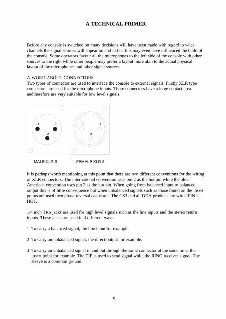
A WORD ABOUT CONNECTORSTwo types of connector are used to interface the console to external signals. Firstly XLR typeconnectors are used for the microphone inputs. These connectors have a large contact areaandtherefore are very suitable for low level signals.
3
2 11 2
3
FEMALE XLR-3MALE XLR-3
It is perhaps worth mentioning at this point that there are two different conventions for the wiringof XLR connectors. The international convention uses pin 2 as the hot pin while the olderAmerican convention uses pin 3 as the hot pin. When going from balanced input to balancedoutput this is of little consequence but when unbalanced signals such as those found on the insertpoints are used then phase reversal can result. The CS3 and all DDA products are wired PIN 2HOT.
1/4 inch TRS jacks are used for high level signals such as the line inputs and the stereo returninputs. These jacks are used in 3 different ways.
1 To carry a balanced signal, the line input for example.
2 To carry an unbalanced signal, the direct output for example.
3 To carry an unbalanced signal in and out through the same connector at the same time, theinsert point for example. The TIP is used to send signal while the RING receives signal. Thesleeve is a common ground.
A TECHNICAL PRIMER

10
TIPRINGSLEEVE
TIP CONNECTION
RING CONNECTION
SLEEVE CONNECTION AND CABLE CLAMP
1/4 INCH TRS ’A’ GAUGE JACK PLUG
A technique known as "normalling" or "innering" can be used to carry signal through jackswhich have no plugs inserted. The jack socket is equipped with spring terminals making contactwith the tip, ring and sleeve connections until a plug is inserted. Signal wired to these sprungconnections will normally connect to the tip, ring and sleeve connections and an example of thisis where the auxiliary left input is also used as a mono input by wiring it through to the rightinput connector.
NORMALTIP
RINGNORMAL
INNERS
FRAME
NORMALTIP
RINGNORMAL
INNERS
FRAME
LEFTINPUT
RIGHTINPUT
Thus a mono input signal is fed to both left and right signal paths. If a stereo input is requiredthen the insertion of a jack plug into the right jack cuts off the signal from the left jack letting theright and left signals go the appropriate signal paths. Another example is the insert jack wherethe tip and ring inner connections are wired together. When the insert point is not in use signalfed to the tip is returned to the ring through the normalled connections then to proceed throughthe remainder of the module.
NORMALTIP
RINGNORMAL
INNERS
FRAME
INSERT POINT
TO EFFECT
FROM EFFECT

11
BALANCED OR UNBALANCED ?Relating to a home stereo system unbalanced operation is the norm with the ground being used asthe signal return path. This can be prone to interference especially with the longer cable lengthsused in professional applications.
To counter this, balanced operation is usually preferred where the signal send and return use twoindividual signal wires which will normally have an overall screen. Thus XLRs have 3 pins, twofor the balanced signal and one for ground which is now used for screening purposes, rather thanas a signal return path. It is common practise to have the ground connected at one end of a cableonly to reduce the risk of ground loops which can induce hum and interference into the wantedaudio signal. When jacks are used they must be of the TRS (Tip, Ring, Sleeve) type to carry abalanced circuit.
The internal electronics of the console are unbalanced therefore every balanced input must have abalanced to unbalanced input stage and every balanced output must have an unbalanced tobalanced output stage. These stages also modify the level of the signal such that the internalconsole signal is optimised for noise and distortion.
INTERCONNECTIONA number of points require to be addressed when connecting inputs and outputs together if eitheror both are unbalanced. The crucial points are grounding and how the screen is connected. Thefollowing table gives an indication of the connections under all possible cases. Note that"balanced" means balanced and floating such as from a transformer while "differential" refers toan electronically balanced input or output which cannot float.
Output Input Screen See Note
Unbalanced Unbalanced SourceUnbalanced Balanced SourceUnbalanced Differential SourceBalanced Unbalanced Destination 1Balanced Balanced SourceBalanced Differential Destination 2Differential Unbalanced Source 3Differential Balanced SourceDifferential Differential Source
1 The shield is connected to the destination earth point, which is the opposite of normal practice,because the signal wires being shielded are referenced to the input earth, not the output earth.
2 If the output transformer is centre tapped to earth, the screen should be connected at thesource.

12
3 When an active differential output is operated in unbalanced mode, it is very important that theoutput current returns to earth via the shortest, least reactive route. Check for instability at theoutput.
A simple test to show the vulnerability of of any piece of equipment to earth currents has beenproposed by John Windt in the June 1995 issue of the Journal of the Audio Engineering Society.The test consists of passing a peak AC current of 100mA through the ground system of a piece ofequipment and measuring the degradation in signal to noise ratio. In its simplest form this wouldbe at 50/60Hz, although a more elaborate test could consist of a wide band frequency sweep from20Hz to 200kHz as suggested by Cal Perkins in the same issue of the AES Journal. Of course,there are many different ground paths possible, so it is necessary to try as many as possible, suchas pin1 to pin 1 of any XLR connectors or to the jack sleeves or to the metalwork etc. The resultsof this test are far from subtle, with 30-50db reductions in signal to noise ratio quite commonlyobserved! The scary thing is that this can actually represent a real world situation, unlike asimple bench test measurement of noise, which is usually taken in an idealised situation. A welldesigned and implemented internal grounding method, as found in the CS3, should ensure thatthere is negligible effect on performance.
DECIBELS (dBs)Many signal levels are quoted in dBs as this relates more to the perceived effect of the signals.0dBm relates to a power level of 1mWatt into 600 ohms giving 0.775 Volt. Normally 600 ohmimpedances are not used and dBu are quoted meaning 0.775 Volt independent of impedance.dBV are encountered more and more frequently and they are referenced to 1V. Thus there is adifference of 2.2dB between 0dBu and 0dBV. When dBs are used without a suffix it simplymeans that they are a ratio of two readings and the absolute measurement is not important. Thusthe ratios in dBu's or dBV's are the same but absolute measurements are made to differentreference levels.
Many products operate at +4dBu while many newer semi-professional products including some 1inch multi track tape machines operate at -10dBV. This leads to approximately a 12dB differencebetween signal levels as -10dBV equates to -7.8dBu.
PANNINGWhen a signal is split across a stereo bus some compromise is involved regarding the levels sentto the buses for the following reasons.
Two identical signals, when combined electrically, will double in amplitude which is an increaseof 6dB. If the signals are fed through a stereo loudspeaker system then the acoustic summing andperceived effect is that the signal amplitude has increased by 3dB. There is thus a 3dB differencebetween the two summing mechanisms.

13
For a console optimised for sound reinforcement the pan pot should be 3dB down in the centreposition while for broadcasting where peak levels are important due to transmitter and land lineoverloading, the pan pot should be 6dB down. 4.5dB is often chosen because it is halfwaybetween the extremes. An error of 1.5dB is acceptable in most situations.
Splitting the signal across an LCR bus is similar as only two of the buses are active at any time.If the signal is centrally panned then only the centre (mono) output is active.
The CS3 pan pots are 3dB down in the centre position relative to fully left and right pannedsignal levels.
14
THE INPUT SECTIONChannels to be used with microphones should have their MIC/LINE switches set in the MICposition. Some microphones require phantom power and if this is the case then the 48V switchshould be depressed. This is likely to cause a loud click or thump and it is recommended that theswitch is pressed with the channel fader closed. It is also adviseable to plug the microphone inbefore switching on the phantom rather than to plug the microphone in with the phantom voltagealready on.
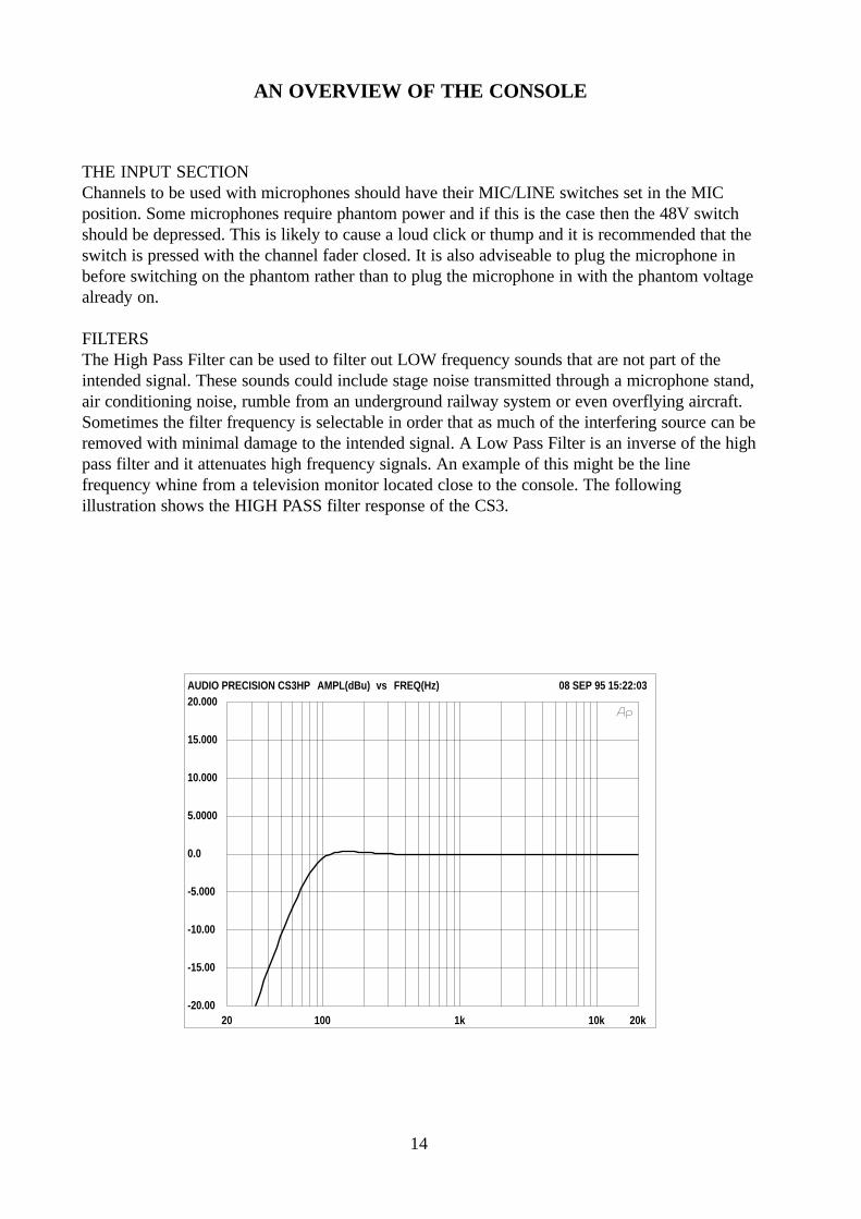
FILTERSThe High Pass Filter can be used to filter out LOW frequency sounds that are not part of theintended signal. These sounds could include stage noise transmitted through a microphone stand,air conditioning noise, rumble from an underground railway system or even overflying aircraft.Sometimes the filter frequency is selectable in order that as much of the interfering source can beremoved with minimal damage to the intended signal. A Low Pass Filter is an inverse of the highpass filter and it attenuates high frequency signals. An example of this might be the linefrequency whine from a television monitor located close to the console. The followingillustration shows the HIGH PASS filter response of the CS3.
AN OVERVIEW OF THE CONSOLE
20 100 1k 10k 20k
FREQ(Hz)
-20.00
-15.00
-10.00
-5.000
0.0
5.0000
10.000
15.000
20.000AMPL(dBu)AUDIO PRECISION CS3HP vs 08 SEP 95 15:22:03

15
20 100 1k 10k 20k
FREQ(Hz)
-20.00
-15.00
-10.00
-5.000
0.0
5.0000
10.000
15.000
20.000AMPL(dBu)AUDIO PRECISION CS3MID1 vs 08 SEP 95 14:58:37
EQUALISATIONThe equaliser can be used to correct or alter the frequency spectrum of the channel signal. In itssimplest form there will be two sections giving high and low frequency boost and cut. This isvery similar to the tone controls found on home audio systems and adjustment will depend uponthe difference between the source signal and the required sound. The characteristics of theequaliser can sometimes be changed from peaking to shelving and this affects the way theextremes of the frequency ranges are adjusted. A peaking section will, when adjusted to boost ahigh a frequency signal, boost the signal maximally at one frequency before its effect diminishestowards the audible limit. A shelving section will modify all frequencies equally after the initialboost or cut.
Further scope for adjustment can be given with a mid frequency section which is always apeaking section. Usually the frequency is adjustable along with the level of boost/cut. In somecases a Q or WIDTH control can also be fitted - known as a parametric eqaliser. This controls thebandwidth of the equaliser and allows the frequency correction to be more accurately targetedwithout affecting other parts of the spectrum. Both boost and cut are available and this controlcould be used to notch out unwanted sounds rather than boosting wanted sounds. The followingillustration shows the mid range response of the CS3 equaliser at one frequency.

16
INSERT POINTSInsert points allow the signal path in the module to be broken and for an effect device such as acompressor to be inserted. With no jack inserted signal is normalled through to the insert returnpoint but when a jack is inserted this path is broken and the signal from the jack is forced out ofthe module through the effect unit and back through the insert return to join the main signal pathagain.
AUXILIARIESAuxiliary outputs can have many uses and it is probably simplest to consider the auxiliaries asadditional mixing buses. They can be used to send signal to an effect unit such as a reverberationdevice or to develop another mix for use as foldback or monitoring.
Each auxiliary has a master level control which equates to the master faders of the console. Thiscontrols the output level of the auxiliary and the individual channel levels can be adjusted fromthe controls located on the modules. Signals to the auxiliary sends can be switched pre or postfader. In pre fade mode the auxiliary signal will only depend upon the position of the auxiliarysend pot but in post mode the signal will depend both upon the channel fader position and theposition of the auxiliary pot.
DIRECT OUTPUTSDirect outputs can be used to feed effects devices or even the inputs to a multitrack tape recorder.The Direct Output is post fader/post cut and therefore its level depends on the channel fader.Only the signal going through the module is available on the direct output and no mixing withsignals from other channels can take place inside the console.
ROUTING AND PANNINGRouting switches allow the signal to be sent to the various mix buses within the console. Inaddition to the groups it is possible to send to the L/R or stereo mix bus and the mono or centrebus.
A pan control allows the signal to be panned or spread across a pair of groups or the stereo mixcreating a stereo signal from a mono one. The pan control effectively splits the signal into leftand right components with their amplitudes depending upon the rotation of the pan control. In thecentre position equal levels should be sent to both left and right or odd and even groups. Ifpanned hard left then the left signal should be 3dB higher than with the pan control in the centreposition while there should be no signal on the right side. This situation is reversed with a hardright pan.
The pan control can also be switched into LCR mode and rather than panning from left to rightthe pan will now work between left/centre and centre/right. With the pan in the centre positionthen signal will only appear on the centre output.

17
THE SOLO SYSTEMThe solo system can often be one of the more complex aspects of a console. The intention is toallow signal to be previewed without affecting the outputs of the console, other than the monitoroutput. Solo can also be referred to as AFL, PFL or SIP.
AFL or after fade listening gives the ability to listen to signals in isolation which are derivedfrom a point after the channel fader.
PFL or pre fade listening allows signals derive from before the channel fader to be monitored.Both AFL and PFL modes use dedicated buses which are switched through to the monitoroutputs of the console when required.
SIP or Solo-In-Place operates very differently by cutting all the other signals routed to the mainbuses of the console allowing the selected signal to be heard in isolation.
THE MASTER MODULEThe simplest signal path to follow is when the signal is routed to the stereo mix bus. The mixoutputs are located on the master module and contain an insert point, a peak indicator, a faderand a balanced output stage. The insert point can be used to insert an effect device as is the casewith the input module. Note that the bus peak led comes before the insert point and therefore anygain introduced at the insert point will not be indicated by it.
A tape recorder output is also connected at the insert send point operating at -10dBV andunbalanced. The master output is taken from after the master fader, operates at a nominal level of+4dBu and is fully balanced. If required the output can be run into an unbalanced load withoutany modification. The output of the master fader is taken to the master meters for a visualindication of the console output level. If a solo is selected on any module then the left meter willindicate the solo level and the monitoring will switch so that the solo can be heard
The master module has provision for a tape return and this can be assigned through a levelcontrol to the L/R and Mono outputs of the console or it can be assigned to the monitor system.
Tape to L/R assigns the tape signal to the main buses AFTER the main fader giving anintermission playback facility independent of the master faders in the console.
THE GROUP OUTPUTSThe group output stages are located on the group modules and have their own master faders togive overall control of the group level.

18
The group output may be used either to feed a tape recorder or to send to another destinationsuch as a power amplifier. If required the group can be sub mixed down onto the stereo bus ofthe console. This makes it easier to control the level of all the channels assigned to the group asonly the one master fader will alter the level of the entire group. Individual faders on thechannels can of course still be moved to alter the balance within the group.
The group output is almost identical to the main output having a group insert point, a peak led, agroup fader and a balanced group output stage. In addition there is a group meter, a group CUTswitch, a group solo switch, and a pan control working with the MIX switches. These allow thesignal to be sub mixed onto either the stereo or the mono buses of the console and LCR panningcan be selected. If required signal could be taken from the group output at the same time as thegroup is subbed onto the L/R and MONO mix buses but without independent level control.
THE AUXILIARY OUTPUTSThe auxiliary master outputs are located on the same modules as the group outputs and have asimple signal path. The signals on the auxiliary buses are mixed and then go through an auxiliaryinsert point before the master level control which is a rotary potentiometer rather than a fader.The output of the level control goes to a balanced output stage. There is no meter associated withthe auxiliary outputs although they can be soloed to check the signal level.
STEREO INPUTSThere is a stereo input associated with each group output. This allows a line level stereo (ormono) signal to be fed into the console through a fader for level control, to be balanced and thento be routed to the group buses or the main L/R or Mono buses. In the event of a large mix theymay assist in creating the required number of inputs or if consoles are linked together then theymay be used to carry the outputs of the slave console onto the buses of the master console. Theinput jacks are wired such that if a mono signal is fed to the left input then it will also be routedto the right input through the normalling connections of the jack sockets.

19
INSTALLATION GUIDE
There are a number of points to consider when installing a mixing console. Many of these pointswill have been addressed before the console is even unpacked but it is worth repeating themagain.
POSITIONThe console should be located in a convenient space commensurate with the use to which theconsole is being put. Ideally a cool area is preferred not in close proximity to power distributionequipment or other potential sources of interference. Provision should be made for some flatsurface surrounding the console to prevent people using it as a table top. One of the worst fatesthat can befall a console is for a cup of coffee to be tipped into it by someone resting it on thecontrol surface!
POWERThe power supply should be located as far from the console as the connecting cable will allow. Itshould be set for the appropriate line voltage and plugged into the mains outlet using the suppliedcable.
WIRINGThe console uses four different connector styles:-
TRS jack sockets, XLR male connectors, XLR female connectors and phono connectors.
TIPRINGSLEEVE
TIP CONNECTION
RING CONNECTION
SLEEVE CONNECTION AND CABLE CLAMP
1/4 INCH TRS ’A’ GAUGE JACK PLUG1/4 INCH TRS ’A’ GAUGE JACK PLUG
3
2 11 2
3
FEMALE XLR-3FEMALE XLR-3MALE XLR-3MALE XLR-3
PHONO SOCKETS
PHONO PLUG

20
The cables used should be of as high a quality as possible. Many installation problems can betraced back to poor or faulty cables and connectors.
As mentioned before there are two different conventions for the wiring of XLR connectors. Theinternational convention uses pin 2 as the hot pin while the older American convention uses pin 3as the hot pin. When going from balanced input to balanced output this is of little consequencebut when unbalanced signals such as those found on the insert points are used then phase reversalcan result. The CS3 and all DDA products are wired PIN 2 HOT.
ATTENTION
CABLESThis product should only be used with high quality, screened twisted pair audio cables,terminated with metal bodied 3-pin XLR connectors. The cable shield should be connected to Pin1. Any other cable type or configuration for the audio signals may result in degradedperformance due to electromagnetic interference.
ELECTRIC FIELDSShould this product be used in an electromagnetic field that is amplitude modulated by an audiofrequency signal (20Hz - 20kHz), the signal to noise ratio may be degraded. Degradation of up to60dB at a frequency corresponding to the modulation signal may be experienced under extremeconditions (3V/m, 90% modulation).
No permanent damage or degradation of performance will be caused by these conditions.

21
THE INPUT MODULE
The input modules contain the signal processing circuits that match externalsignals to the internal electronics of the console.
An input stage is followed by a filter and equalisation stage before the signalis passed through the fader to be routed to the various outputs of the console.
The equaliser can be used creatively to modify signals either because theycontain unwanted sounds or because they need to be matched more closelyto other sounds in the overall balance.
LCR EXPLAINEDThree channel left centre right panning differs from the normal stereopanning arrangement in that where the conventional left/right pan moves thesignal across the stereo image, LCR panning moves the signal between threedistinct positions. Using LCR panning gives a more spatial effect, offersmore control over vocals and effect positioning and really bringsperformances to life.
In LCR mode the pan pot acts as follows:-
When panned hard left the signal is only fed to the left channel of the mainoutput. As the pan is rotated towards the centre, the signal to the leftdecreases and the signal to the centre channel increases until at a dead centrethe signal only goes to the centre output. At this point no signal is fed to theright channel.
Rotating the pan pot further to the right decreases the centre feed while theright feed increases until at full clockwise rotation the signal is only on theright channel.
Soloists are typically mixed to the centre channel while back up vocals, anorchestra or a band can be wrapped around the soloist in stereo or pannedacross the three channels.

22
+48VProvides 48 volt phantom power for a condenser microphone, or D.I. box.Optional balancing transformers may be fitted on the Mic/Line input.
GAINThe gain control is a wide range rotary potentiometer, and is active on both Mic andLine Inputs. With Mic selected the gain can be adjusted from 20dB to 70dB. ForLine inputs, the adjustment is from -10dB to +20dB.
MIC/LINESwitching this inserts an attenuator into circuit with the microphone/line input andalters the range of gain adjustment available. This should be pressed when high levelor line level signals are connected to the channel through the line input jack. Notethat if a jack is not inserted into the line input socket then the XLR connector maybe used as the line input.
EQUALISERThe equaliser on the input module is a three band design, incorporating a parametricmid-range section and fixed frequency shelving high and low frequency sections.
HFA high frequency equaliser, providing 15dB of boost or cut at 12kHz.
MIDA parametric middle frequency equaliser, providing 15dB of boost or cut. The
frequency is adjustable from 500Hz to 15kHz and the Q or bandwidth can be swept between thevalues of 0.7 and 4.5. In octave values this means 2 octaves at the widest (low Q) setting and about athird of an octave at the narrowest (high Q) setting. This enables the part of the audio spectrumrequiring adjustment to be targeted very precisely and reduces the effect on parts of the signal thatrequire no modification.
LFA low frequency equaliser, providing 15dB of boost or cut at 80Hz.
FILTERThe Filter switch inserts a 80Hz highpass filter with a rolloff of 18dB per octave into circuit after theinput amplifier. This may be used to eliminate unwanted low-frequency noises transmitted to themicrophone through a floorstand for example.
An insert point is located after the EQ section allowing the introduction of an effect unit or similar intothe signal path..AUXILIARIES

23
There are six auxiliary outputs. Additionally, the channel direct output may be used toprovide a dedicated auxiliary send.
AUX 1Controls the level of the channel signal fed to Auxiliary 1. This signal is normally pre-fader.
AUX 2Controls the level of the channel signal fed to Auxiliary 2. This signal is normally pre-fader.
Link OptionsLink 3 is normally installed causing the signal fed to auxiliaries 1 and 2 to be pre fade,although they will mute if the channel is muted.Link 4 will make the signal pre equaliser and independent of the mute.Link 5 will enable the auxiliaries to send post fader signal.Link 10 allows auxiliaries 1 and 2 to be fed from an output of the pre switch and links 8 and 9will then determine which pre signal is selected.Link 8 is normally installed giving a pre fade, post cut signal.Link 9 will give a pre equaliser feed.
AUX 3Controls the level of the channel signal fed to Auxiliary 3.
AUX 4Controls the level of the channel signal fed to Auxiliary 4.
PRENormally this operates on auxiliaries 3 and 4 to change them from a post fade feed to a pre fade feed.
Link OptionsLinks 6 and 7 determine the pre feed fade. Link 6 is normally installed giving a pre fade, post cut signal. If link 7 isinstalled the PRE feed will be pre equaliser. If link 10 is installed the PRE button will affect auxiliaries 1 and 2.If link 12 is installed the PRE button will affect auxiliaries 5 and 6.
AUX 5/AUX 6Controls the level of the channel signal fed to Auxiliary 5 and Auxiliary 6.
Link 11 is normally installed giving auxiliaries 5 and 6 a post fader feed.
Link OptionsIf link 12 is installed the feed will depend on the PRE switch.If link 13 is installed the feed will be pre-equaliser.If link 14 is installed the feed will be pre fade, post cut.
ROUTING AND STATUS

24
L/R (LCR)This changes the pan pot into a left, centre, right pan pot. The signal now pansbetween left and centre or right and centre. It is not possible therefore to havesignal on the left and right buses simultaneously from one module if LCR mode isselected. With the pan pot in the centre position there will only be signal on thecentre output.
PANWhen PAN is set to centre in L/R mode, equal levels are sent to the left/right(odd/even) buses, with a 3dB drop relative to the fully clockwise or anticlockwisepositions. Setting the PAN control fully anticlockwise sends full level to the Leftbus, cutting the send to the Right bus. Fully clockwise rotation sends full level tothe Right bus, cutting the feed to the Left bus.
CUTThe CUT switch disables the channel signal path, and is indicated by an led in theswitch when the channel is muted. When CUT, all post-fade auxiliary sends androuting assignments are muted in addition to the pre fade, post cut sends.
MIXRoutes the post-fade, post-pan channel signal to the stereo mix bus or the left,centre and right buses if LCR panning is selected.
MONORoutes the post fader signal to the mono or centre bus. In L/R pan mode withMIX selected no signal will be routed to the mono output if this switch is notdepressed. With the pan control in LCR mode and MIX selected the centreoutput of the pan pot is routed to the mono or centre bus without this button beingpressed. If the button is pressed the the pan pot output will be replaced by thepost fade signal.
PANPressing this allows the output of the pan pot to be sent to the groups. An odd
and an even group should be used when panning across groups and the pan controlwill operate as described for the left and right buses above. If this switch is not pressed then theselected groups will receive identical mono signals which are not dependent upon the pan pot position.Pan mode should be set for L/R operation.
1 (or 2,3,4)Routes the post-fade, (post-pan if selected) channel signal to output group 1 (or 2, 3, 4).

25
PFLThe PFL button feeds the post insert return signal to the Monitor Section (loudspeakers orheadphones), replacing the selected monitor source. The main stereo and centre outputs of the consoleare not affected. The led in the PFL switch will illuminate when the PFL function is active and PFLsignals from different channels that are active simultaneously will be mixed together. If Solo In Placemode is selected (on the master module) then all other channels on the console will be muted while onlythe channel initiating the solo will be heard. This allows signals to be previewed exactly as they willappear in a mix but in isolation. Note that this is no longer PFL.
PEAKThis led (light emitting diode) indicates when the signal is getting close to clipping level. If clipping occursthe signal will be severely distorted and the channel input gain should be reduced.
SIGNALThis led shows when signal is present in the channel and is simply a useful aid on occasions when nooutput can be found from the console. It establishes that there is input signal and that maybe there is arouting or some other problem.
FADERThe fader is the main signal level control for the channel, and is a long-throw type giving smooth controlof the channel level. Note that the fader is calibrated and the normal operating position is expected to beclose to the 0dB mark.
If the fader is significantly lower than this then the input signal is too high and either the input gain control(near the top of the module) should be reduced or the MIC/LINE switch pressed to select the lineinput. If this action is not taken distortion may result.
If the fader has to be pushed above the 0dB point then this indicates that the input signal is low and thatthe input gain should be increased or the MIC/LINE switch set for microphone operation. If this actionis not taken the signal may contain more noise than necessary.

26
CONNECTORS AND PIN DEFINITIONS
Mic Input : 3 Pin Female XLR type, BalancedNominal Input Level: -16dBu to -66dBuPin 2: Signal +ve (Hot)Pin 3: Signal -ve (Cold)Pin 1: GroundInput Impedance : >2 kOhm
Line Input : 1/4" TRS Jack Socket, ‘A’ Gauge, BalancedNominal Input Level: -16dBu to +14dBuTip : Signal +ve (Hot)Ring : Signal -ve (Cold)Sleeve : GroundInput Impedance : >10 kOhm
Insert Point : 1/4" TRS Jack Socket, ‘A’ Gauge, UnbalancedNominal Input/Output level: -2dBuTip : Insert SendRing : Insert ReturnSleeve : GroundOutput Impedance: <75 OhmInput Impedance : >10 kOhm
Direct Output :1/4" TRS Jack Socket, ‘A’ Gauge, UnbalancedNominal Output level: -2dBuTip : SignalRing : GroundSleeve : GroundOutput Impedance: <75 Ohm
Remote Connector1 Ground2 Mute Input Grounding this pin mutes or cuts the channel.3 Mute Output This pin is grounded when the CUT switch is depressed.

27
INPUT MODULE BLOCK DIAGRAM
MONO
LEFT
RIGHT
GROUP 1
GROUP 2
GROUP 3
GROUP 4
AUXILIARY 1
AUXILIARY 2
AUXILIARY 3
AUXILIARY 4
AUXILIARY 5
AUXILIARY 6
SOLO IN PLACE
OUTPUT SOLO
INPUT SOLO
IP CUE CONTROL
OP CUE CONTROL
MONOINSERT DIRECTHPF
LF HFRANGE
PAD
JACK 8 2
6 41
48V
OPTXFMR
EQUALISER80Hz
CUT
FADER
Q
FREQ
+/-
LCR
PAN
PAN
MIX
1
2
3
4
INPUT SOLOIPCUEDC
SIP
SOLOCUT
EXTERNALCUT OUT
XLR
123
REMOTE
EXTERNALCUT IN
CUT
PEAK
1
2
SIGNAL
AUXCUT
1 2
1 2
1 2
PRE
1 2
1 2
1 2
1 2
1 2
1 2
POST
PRE EQ
PRE
PRE EQ
PRE
PRE EQ
PRE
AUX 1
AUX 2
AUX 3
AUX 4
AUX 5
AUX 6
1 2
1 2
1 2
POST
PRE EQ
PRE

28
LINK FUNCTION FACTORY FITTED NOTES
1 AUXILIARY PRE CUT FUNCTION Y
2 AUXILIARY PRE CUT FUNCTION N
3 PRE 2 TO AUX 1, 2 Y
4 PRE 1 TO AUX 1, 2 N
5 POST TO AUX 1, 2 N
6 PRE 2 TO AUX 3, 4 Y
7 PRE 1 TO AUX 3, 4 N
8 PRE 2 TO AUX 5, 6 Y
9 PRE 1 TO AUX 5, 6 N
10 AUX 1,2 FOLLOW PRE SWITCH N
11 POST TO AUX 5, 6 Y
12 AUX 5,6 FOLLOW PRE SWITCH N
13 PRE 1 TO AUX 5, 6 N
14 PRE 2 TO AUX 5,6 N
15 DIRECT OUTPUT POST FADE N
16 DIRECT OUTPUT PRE EQ Y
INPUT MODULE LINKS
The above links will not normally require to be altered unless the console is reconfigured for anyreason.
Stereo Input Module
ST
ER
EO
INP
UT
MO
DU
LE
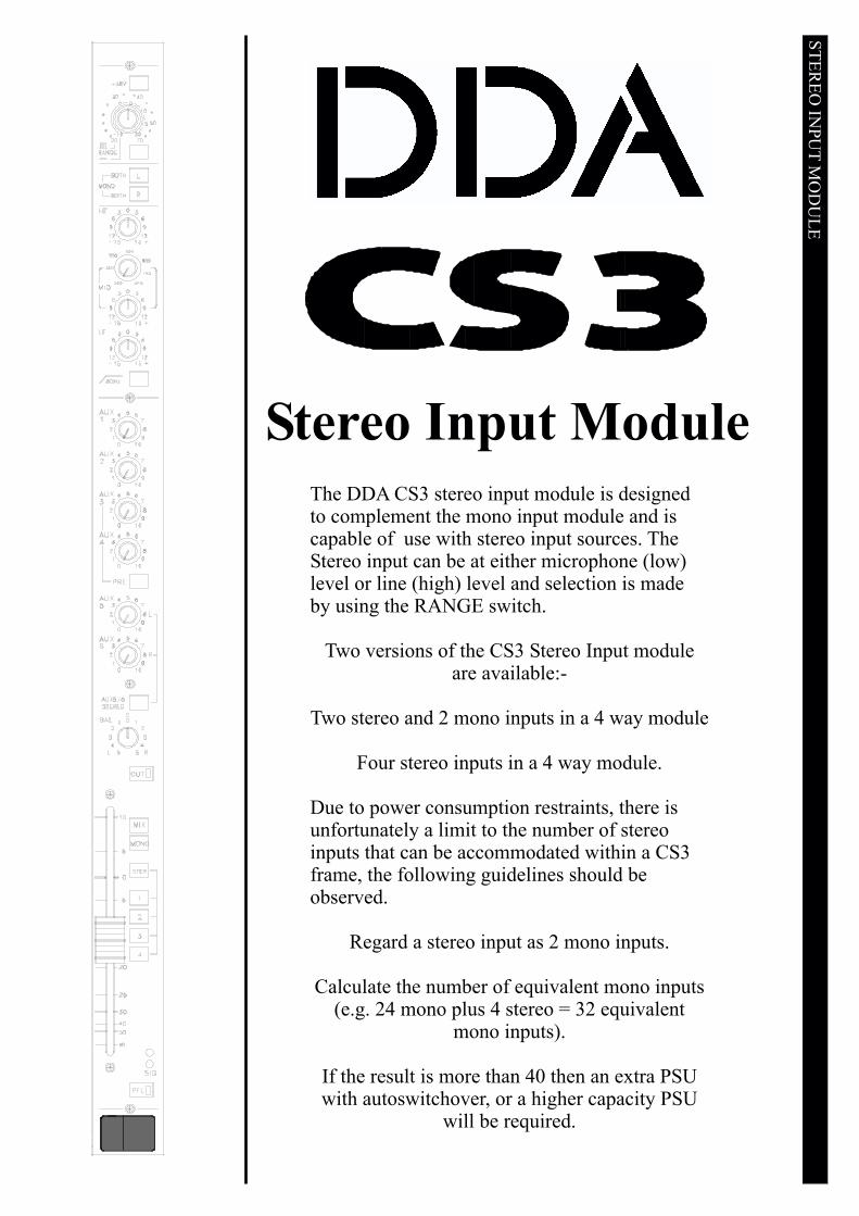
The DDA CS3 stereo input module is designedto complement the mono input module and iscapable of use with stereo input sources. TheStereo input can be at either microphone (low)level or line (high) level and selection is madeby using the RANGE switch.
Two versions of the CS3 Stereo Input moduleare available:-
Two stereo and 2 mono inputs in a 4 way module
Four stereo inputs in a 4 way module.
Due to power consumption restraints, there isunfortunately a limit to the number of stereoinputs that can be accommodated within a CS3frame, the following guidelines should beobserved.
Regard a stereo input as 2 mono inputs.
Calculate the number of equivalent mono inputs(e.g. 24 mono plus 4 stereo = 32 equivalent
mono inputs).
If the result is more than 40 then an extra PSUwith autoswitchover, or a higher capacity PSU
will be required.

+48VProvides 48 volt phantom power for a condenser microphone, orD.I. box.
GAINThe gain control is a wide range rotary potentiometer, and is activeon both Mic and Line Inputs. With Mic selected the gain can beadjusted from 20dB to 70dB. For Line inputs, the adjustment is from-10dB to +20dB.
RANGEPressing this inserts an attenuator into the input circuit and alters therange of gain adjustment available. This should be pressed whenhigh level or line level signals are connected to the channel throughthe line input jack. Note that if a jack is not inserted into the lineinput socket then the XLR connector may be used as the line input.The TRS jack could also be used as a microphone input although itis not recommended.
MONO RThis cuts the LEFT input signal replacing it with the RIGHT inputsignal. Thus the module carries the right input signal through thestereo signal path.
MONO LThis cuts the RIGHT input signal replacing it with the LEFT inputsignal. Thus the module carries the left input signal through thestereo signal path.
If both MONO L and MONO R are pressed together, a mixedleft/right (mono) signal is fed through the stereo signal path of themodule.
HFA high frequency equaliser, providing 15dB of boost or cut at12kHz.
MIDA swept frequency equaliser, providing 15dB of boost or cut. Thefrequency is adjustable from 200Hz to 3k5Hz.
LFA low frequency equaliser, providing 15dB of boost or cut at 80Hz.
80HzThis inserts an 80Hz highpass filter with a rolloff of 18dB per octaveinto circuit after the input amplifier. This may be used to eliminateunwanted low-frequency noises transmitted to the microphonethrough a floorstand for example.
AUXILIARIESThere are six auxiliary sends available on the CS3, with the outputslocated on the master module. Auxiliaries 5 and 6 may be switchedfor use as a stereo pair if required.
AUX 1 / AUX 2Controls the level of the channel signal fed to Auxiliaries 1 and 2.This signal is mono and normally pre-fader.
Link OptionsLink 3 is normally installed causing the signal fed to auxiliaries 1and 2 to be pre fade, although it will mute if the channel is muted.Link 4 will make the signal pre equaliser and independent of themute.Link 5 will enable the auxiliaries to send post fader signal.Link 10 allows auxiliaries 1 and 2 to be fed from an output of thepre switch and links 8 and 9 will then determine which pre signal isselected.Link 8 is normally installed giving a pre fade, post cut signal.Link 9 will give a pre equaliser feed.
ST
ER
EO
INP
UT
MO
DU
LE

AUX 3 / AUX 4Controls the level of the channel signal fed to Auxiliaries 3 and 4.
PRENormally this operates on auxiliaries 3 and 4 to change them from amono post fade feed to a mono pre fade feed.
Link OptionsLinks 6 and 7 determine the pre feed fade. Link 6 is normallyinstalled giving a pre fade, post cut signal. If link 7 is installed thePRE feed will be pre equaliser. If link 10 is installed the PRE buttonwill affect auxiliaries 1 and 2.If link 12 is installed the PRE button will affect auxiliaries 5 and 6.
AUX 5 / AUX 6Controls the level of the channel signal fed to Auxiliary 5 andAuxiliary 6.
Link OptionsIf links 17/18 are installed the feed will be pre equaliserIf links 21/22 are installed the feed will be pre fade, post cut.
The auxiliaries can be used to create additional mixes and in manycases these mixes will be sent to an effects device such as areverberation unit. Another major use of the auxiliaries is providingfoldback to artists in order that they can hear other performers or abacking track perhaps. Sometimes stereo foldback is preferred andauxiliaries 5 and 6 can be configured for stereo use. It is evenpossible to send stereo foldback from the mono inputs by adjustingthe levels sent to auxiliaries 5 and 6. When the levels are equal theimage will appear central but by adjusting the relative levels of auxand 6 the image will appear to move away from centre.
ROUTING AND STATUS
CUTThe CUT switch disables the channel signal path and is illuminatedby an led when the channel is muted. When CUT, all post-cutauxiliary sends and routing assignments are muted.
BALThis alters the relative left and right levels of the stereo signal ontothe left and right buses of the console. It works as a pan controlgiving full attenuation of the unwanted side at extremes of travel.
MIXRoutes the post-fade, post-pan channel signal to the stereo mix bus.
MONORoutes the post fader mono signal to the mono or centre bus.
1 (or 2,3,4)Routes the post-fade, mono signal to output group 1 (or 2, 3, 4).
STEREORoutes post pan stereo signal to the groups. The odd groups (1 and3) will carry the left signal while the even groups (2 and 4) willcarry the right signal.
PFLThe PFL button feeds the pre fade signal to the Monitor Section(loudspeakers or headphones), replacing the selected monitor source.The main stereo and centre outputs of the console are not affected.The led in the PFL switch will illuminate when the PFL function isactive and PFL signals from different channels that are activesimultaneously will be mixed together. If Solo In Place mode isselected (on the master module) then all other channels on theconsole will be muted while only the channel initiating the solo willbe heard. This allows signals to be previewed exactly as they willappear in a mix but in isolation. Note that this is no longer PFL.
ST
ER
EO
INP
UT
MO
DU
LE
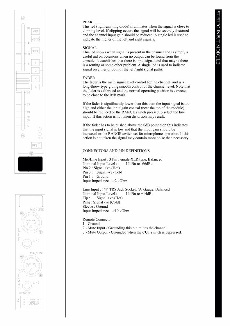
PEAKThis led (light emitting diode) illuminates when the signal is close toclipping level. If clipping occurs the signal will be severely distortedand the channel input gain should be reduced. A single led is used toindicate the higher of the left and right signals.
SIGNALThis led shows when signal is present in the channel and is simply auseful aid on occasions when no output can be found from theconsole. It establishes that there is input signal and that maybe thereis a routing or some other problem. A single led is used to indicatesignal on either or both of the left/right signal paths.
FADERThe fader is the main signal level control for the channel, and is along-throw type giving smooth control of the channel level. Note thatthe fader is calibrated and the normal operating position is expectedto be close to the 0dB mark.
If the fader is significantly lower than this then the input signal is toohigh and either the input gain control (near the top of the module)should be reduced or the RANGE switch pressed to select the lineinput. If this action is not taken distortion may result.
If the fader has to be pushed above the 0dB point then this indicatesthat the input signal is low and that the input gain should beincreased or the RANGE switch set for microphone operation. If thisaction is not taken the signal may contain more noise than necessary.
CONNECTORS AND PIN DEFINITIONS
Mic/Line Input : 3 Pin Female XLR type, BalancedNominal Input Level : -16dBu to -66dBuPin 2 : Signal +ve (Hot)Pin 3 : Signal -ve (Cold)Pin 1 : GroundInput Impedance : >2 kOhm
Line Input : 1/4" TRS Jack Socket, ‘A’ Gauge, BalancedNominal Input Level : -16dBu to +14dBuTip : Signal +ve (Hot)Ring : Signal -ve (Cold)Sleeve : GroundInput Impedance : >10 kOhm
Remote Connector1 - Ground2 - Mute Input - Grounding this pin mutes the channel.3 - Mute Output - Grounded when the CUT switch is depressed.
ST
ER
EO
INP
UT
MO
DU
LE

29
Each Group Output Module contains a Group Output stage, an AuxiliaryOutput stage and also a Stereo Input, for use, for example, with externaleffects devices. The group and auxiliary outputs are electronically balancedand may optionally be transformer balanced.
The stereo input can be routed to the stereo mix, the centre bus or the groupbuses. Insert points are provided in the group and auxiliary send signal pathsallowing the connection of external processing devices such as limiter/compressor units.
A twelve segment led meter reads the signal present on the Group output. Itis post fade and post cut and therefore will show no signal if the fader isdown or the group is muted.
The group outputs can be used in their own right as console outputs to befed to loudspeaker systems or tape machine inputs. They can also be submixed onto the main left, right and centre buses of the console creating theability to control the level of several input channels onto the main buseswith one (group) fader.
THE GROUP OUTPUT MODULE

30
STEREO INPUT SECTIONThis is a high (line) level stereo input that can be routed to the left, right,centre and group buses of the console. It could be used to bring a tape machineinto the console without tying up two modules or the output of an effect devicewhether stereo or mono. The input of the effect device would normally be fedfrom an auxiliary output of the console.
BALANCEAdjusts the relative left/right levels of the return signal. This is not to beconfused with the balance referred to in the case of balanced inputs forexample !
Note that if a mono signal is connected to the left input and nothing is pluggedinto the right input the signal will be sent to the left and right signal paths. Thissaves a special cable having to be made or used for mono signal sources. If amono input is connected to the right input then only the right signal path willreceive this signal.
FADERThis is the level control for the return signal, and adjusts the amount of levelsent to the routed outputs.
L/RRoutes the return signal to the L/R stereo mix.
MONORoutes the return signal to the mono or centre mix. The left and right signals are combined tomono for this.
1-2, (3- 4)Routes the return signal to groups 1 and 2 (or 3 and 4).
PFLThis allows the pre fade auxiliary return signal to be soloed. The solo is pre fader and thereforewill not depend on the position of the stereo input fader. In effect it allows the input signal to beviewed on the solo meter and monitored.

31
METERThis meter indicates the level of the group output. It has a VU characteristic.
BUS PEAKThis indicates when the group mix bus level is very high and the signal is indanger of becoming distorted. The signals routed to the group should bereduced in level by pulling their faders down or reducing the input gain of therouted channels.
THE AUXILIARY MASTER SECTION (1 OF 4)Each group output stage contains one auxiliary output section.
LEVELThis controls the auxiliary output level.
AFLThis allows the auxiliary signal to be previewed. The post fade auxiliarysignal is used and therefore it is dependent on the position of the output levelcontrol.
There is an auxiliary insert point allowing the insertion of an effect unit into the auxiliary signalpath, pre the level control.

32
THE GROUP OUTPUT SECTION
L/R (LCR)This changes the pan pot from standard mode to LCR mode where the signalwill pan between left and centre or right and centre.
CUTThe CUT switch disables the channel signal path, and is indicated by a led inthe switch when the group is muted.
PANThis adjusts the relative levels of signal sent to the left and right outputs or theleft, centre and right outputs depending upon the selected pan mode whenMIX is pressed.
FADERThe fader controls the level of the group output. As with the input module,fader operation close to the 0dB calibration point is expected and any largedeviation from this would indicate that the signal from the modules feedingthe group are too high or too low.
MIXWhen MIX is pressed the group signal is sent to the stereo mix. The pancontrol can be switched to LCR mode and the centre bus will then be fed withthe centre output of the pan pot without the MONO button being pressed.
MONOThis feeds the post fade group signal to the mono or centre bus of the consolewhen pressed. In LCR mode the centre output of the pan pot will be replacedby the post fader signal if this switch is pressed. In L/R mode the centreoutput will not receive a signal until this switch is pressed.
AFLAllows the post fader pre cut group signal to be soloed. Thus the AFL level indicated on the solometer will depend upon the group fader but not on the CUT switch.
There is a pre-fader group insert point allowing an effect unit or similar to be introduced into thesignal path.

33
GROUP MODULE LINKS
LINK FUNCTION FACTORY FITTED NOTES
1 BUS 1 TO GROUP OUTPUT Y
Depends upon themodule position.Position 1 illustrated.
2 BUS 2 TO GROUP OUTPUT N
3 BUS 3 TO GROUP OUTPUT N
4 BUS 4 TO GROUP OUTPUT N
5 BUS 5 TO GROUP OUTPUT N
6 BUS 6 TO GROUP OUTPUT N
7 BUS 7 TO GROUP OUTPUT N
8 BUS 8 TO GROUP OUTPUT N
9 AUX 1 BUS TO AUX OUTPUT Y
Depends upon themodule position.Position 1 illustrated.
10 AUX 2 BUS TO AUX OUTPUT N
11 NOT USED
12 AUX 3 BUS TO AUX OUTPUT N
13 AUX 4 BUS TO AUX OUTPUT N
14 AUX 5 BUS TO AUX OUTPUT N
15 AUX 6 BUS TO AUX OUTPUT N
16REMOVE IF TRANSFORMERUSED ON AUX OUTPUT
Y
Used to bypass thetransformer position.
17REMOVE IF TRANSFORMERUSED ON AUX OUTPUT
Y
18REMOVE IF TRANSFORMERUSED ON GROUP OUTPUT
Y
19REMOVE IF TRANSFORMERUSED ON GROUP OUTPUT
Y
20 MATRIX BUS ASSIGNMENT N OPTION
The above links will not normally require to be altered unless the console is reconfigured for anyreason.

34
CONNECTORS AND PIN ASSIGNMENTS
Group Output : 3 Pin Male XLR Type, BalancedNominal Output Level: +4dBuPin 2 : Signal +ve (Hot)Pin 3 : Signal -ve (Cold)Pin 1 : GroundOutput Impedance : <75 Ohm
Auxiliary Output : 3 Pin Male XLR Type, BalancedNominal Output Level: +4dBuPin 2 : Signal +ve (Hot)Pin 3 : Signal -ve (Cold)Pin 1 : GroundOutput Impedance : <75 Ohm
Stereo Inputs : TRS Jack Socket, ‘A’ Gauge, BalancedNominal Input Level: +4dBuTip : Signal +ve (Hot)Ring : Signal -ve (Cold)Sleeve: GroundInput Impedance : >10 kOhm
Insert Points : TRS Jack Socket, ‘A’ Gauge, UnbalancedNominal Input Level: -2dBuTip : Insert SendRing : Insert ReturnSleeve: GroundOutput Impedance : <75 OhmInput Impedance : >10 kOhm

35
GROUP MODULE BLOCK DIAGRAM
MONO
LEFT
RIGHT
GROUP 1
GROUP 2
GROUP 3
GROUP 4
AUXILIARY 1
AUXILIARY 2
AUXILIARY 3
AUXILIARY 4
AUXILIARY 5
AUXILIARY 6
SOLO IN PLACE
OUTPUT SOLO
INPUT SOLO
GROUP OUTPUT MET
CUT
GROUP OUTPUT
MONO
8 2
6 41
OPTXFMR
1 2 1 2 1 2 1 2 1 2 1 2 1 2 1 2
INSERT
PEAK
IP CUE CONTROL
OP CUE CONTROL
MIX
MONO
BALANCE
RIGHT
LEFT/MONO
STEREO INPUT
1-2
3-4
1 2 1 2 1 2 1 2 1 2 1 2
INSERT
OPSOLO
AUXILIARY OUTPUT
PANAFL
8 2
6 41
OPTXFMR
AFL
MIX
36
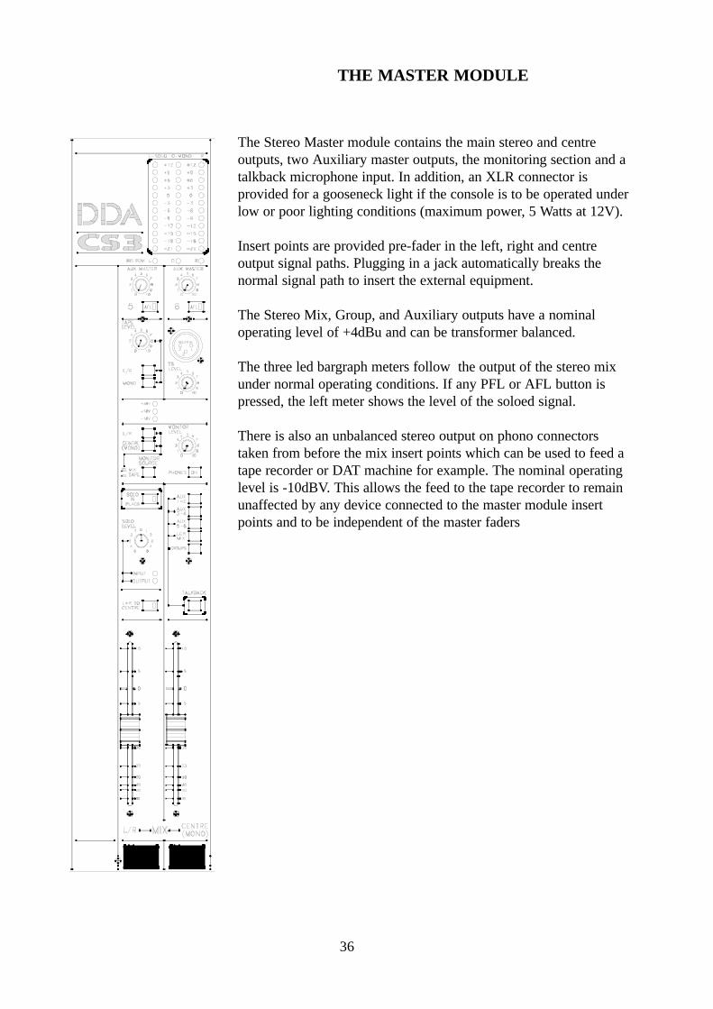
The Stereo Master module contains the main stereo and centreoutputs, two Auxiliary master outputs, the monitoring section and atalkback microphone input. In addition, an XLR connector isprovided for a gooseneck light if the console is to be operated underlow or poor lighting conditions (maximum power, 5 Watts at 12V).
Insert points are provided pre-fader in the left, right and centreoutput signal paths. Plugging in a jack automatically breaks thenormal signal path to insert the external equipment.
The Stereo Mix, Group, and Auxiliary outputs have a nominaloperating level of +4dBu and can be transformer balanced.
The three led bargraph meters follow the output of the stereo mixunder normal operating conditions. If any PFL or AFL button ispressed, the left meter shows the level of the soloed signal.
There is also an unbalanced stereo output on phono connectorstaken from before the mix insert points which can be used to feed atape recorder or DAT machine for example. The nominal operatinglevel is -10dBV. This allows the feed to the tape recorder to remainunaffected by any device connected to the master module insertpoints and to be independent of the master faders
THE MASTER MODULE

37
COMMUNICATIONS
TALKBACK MICA microphone may be plugged in to this socket to provide talkback facilitiesto the output buses. The microphone may be a dynamic type, or by using aninternal link for phantom powering, may be a condenser microphone.
TB LEVELThis adjusts the level of the talkback microphone signal.
AUX 1-2If 1-2 is pressed, the talkback microphone signal is routed to the Auxiliary 1and 2 buses.
AUX 3-4If 3-4 is pressed, the talkback microphone signal is routed to the Auxiliary 3and 4 buses.
AUX 5-6If 5-6 is pressed, the talkback microphone signal is routed to the Auxiliary 5 and 6 buses.
MIXIf pressed the talkback signal is routed to the L/R and Mono (centre) buses.
BUSIf pressed the talkback microphone signal is routed to all the group outputs.
TALKBACKThis allows the talkback signal to pass to the selected destination. When pressed the monitoroutput of the console will dim by 10dB to reduce the possibility of feedback. In normal operationonly this switch would be pressed when talkback is required while the routing switches would beleft assigned to the required destinations.

38
MONITORING
MONITOR LEVELThis controls the level of the local monitor or headphone output.
PHONES ONPressing this enables alternative monitoring through stereo headphones.
MONITOR SOURCEThis switch selects the tape input as the source for the monitoringsystem when pressed.
L/RThis selects the Left/Right outputs of the console to the monitoringsystem when MIX is the selected source, (Monitor Source UP).
CENTRE (MONO)This selects the centre bus to the monitoring system where it is mixedequally onto the left and right monitor signal paths. If TAPE is selectedthe centre feed is cut off and no signal will indicate on the centre meter.
TAPE LEVELThis controls the level of the stereo tape return signal when selected bythe following switches to feed the left, right or centre outputs of theconsole.
L/RThe feeds the tape return signal onto the master left and right outputs ofthe console. Note that this feed is injected after the master faders and thelevel is adjusted by the TAPE LEVEL control.
MONOThis feeds the tape return signal onto the mono or centre output of theconsole. Note that this feed is injected after the master faders and thelevel is adjustedby the TAPE LEVEL control.
The above facilities may be referred to as an intermission playbackfacility.

39
AFL/PFL/SIPSelection of any SOLO (AFL/PFL/SIP) signal will override the monitor selection.
SOLO LEVELThis control allows the audio level of a soloed (PFL/AFL) signal to be adjusted. This will notaffect the solo meter reading.
INPUT SOLOThis led will indicate when a solo has been selected on an input to the console.
OUTPUT SOLOThis led will indicate when a solo has been selected on an auxiliary output or group output.
Priority is given to an input solo. If an output solo is active and an input solo is then activated theoutput solo cannot be heard for the duration of the input solo.
SOLO IN PLACESolo In Place is a solo mode where the monitor system does not change over to listen to the solobus. For SIP mode to operate the monitor selection must be set to MIX. The monitor systemremains listening to the mix outputs and when a solo on an input module is requested a signal issent from the master module to mute all other input modules. Thus only the channel with the solokey pressed will be heard. Output soloes will continue to operate as normal and will take priorityover input soloes. More than one channel can be SIPed at any one time.
L+R TO CENTREThis mixes the post fader left and right outputs onto the centre output of the console.
+18/-18/+48These 3 leds indicate the presence of the two power rails and the phantom voltage supply.
FADERSA stereo LEFT/RIGHT fader and a CENTRE (MONO) fader are provided, giving smoothcontrol of the output signals.
HEADPHONESStereo headphones with impedances from 100 ohms to 600 ohms may be plugged into theheadphone socket. This socket is located below the armrest and to the right hand side of theconsole.

40
METERSThe three meters indicate the levels of the left, centre (mono) and rightoutputs of the console. The left meter is additionally used to indicate sololevels in which case the remaining two meters will not indicate.
BUS PEAK LEDSThere are three leds to indicate peak level on the left, centre and right buses.Any indication here will mean that the level from the input modules, thegroups if sub-mixed into the main outputs, or the stereo inputs is too highand should be reduced to avoid distortion.
THE AUXILIARY MASTER SECTIONAuxiliary master 5 and 6 are locate here.
LEVELThis controls the auxiliary output level.
AFLThis allows the auxiliary signal to be previewed. The post fade auxiliary signal is used andtherefore it is dependent on the position of the output level control.
There is a pre-fader auxiliary insert point allowing the introduction of an effect unit or similarinto the auxiliary signal path.

41
LINK FUNCTION FACTORY FITTED NOTES
1
2REMOVE IF TRANSFORMERUSED ON AUX 6 OUTPUT
Y
Used to bypasstransformer position.
3REMOVE IF TRANSFORMERUSED ON AUX 6 OUTPUT
Y
4REMOVE IF TRANSFORMERUSED ON CENTRE MIX OUTPUT
Y
5REMOVE IF TRANSFORMERUSED ON CENTRE MIX OUTPUT
Y
MASTER MIX CIRCUIT BOARD
LINK FUNCTION FACTORY FITTED NOTES
1REMOVE IF TRANSFORMERUSED ON AUX 5 OUTPUT
Y
Used to bypasstransformer position.
2REMOVE IF TRANSFORMERUSED ON AUX 5 OUTPUT
Y
3REMOVE IF TRANSFORMERUSED ON LEFT MIX OUTPUT
Y
4REMOVE IF TRANSFORMERUSED ON LEFT MIX OUTPUT
Y
5REMOVE IF TRANSFORMERUSED ON RIGHT MIX OUTPUT
Y
6REMOVE IF TRANSFORMERUSED ON RIGHT MIX OUTPUT
Y
MASTER MODULE LINKS
The above links will not normally require to be altered unless the console is reconfigured for anyreason.
CENTRE MIX CIRCUIT BOARD

42
CONNECTORS AND PIN DEFINITIONS
Left and Right Outputs : 3 Pin XLR type, BalancedNominal Output Level: +4dBuPin 2 : Signal +ve (Hot)Pin 3 : Signal -ve (Cold)Pin 1 : GroundOutput Impedance : <75 Ohm
Mono (Centre) Output : 3 Pin XLR type, BalancedNominal Output Level: +4dBuPin 2 : Signal +ve (Hot)Pin 3 : Signal -ve (Cold)Pin 1 : GroundOutput Impedance : <75 Ohm
Tape Play Inputs : Phono SocketsNominal Input Level: -10dBVTip : Signal +ve (Hot)Sleeve: GroundInput Impedance : >40 kOhm
Tape Record Outputs : Phono SocketsNominal Output Level: -10dBVTip : Signal +ve (Hot)Sleeve: GroundOutput Impedance : 1k5 Ohm
Insert Points : 1/4" TRS Jack socket, ‘A’ Gauge, UnbalancedNominal Input level: -2dBuTip : Insert SendRing : Insert ReturnSleeve: GroundOutput Impedance: <75 OhmInput Impedance: >10 kOhm
Monitor Outputs : 3 Pin XLR type, BalancedPin 2 : Signal +ve (Hot)Pin 3 : Signal -ve (Cold)Pin 1 : GroundOutput Impedance : <75 OhmNominal Output level: +4dBu
Headphone Output : TRS Jack Socket, ‘A’ GaugeNominal Output level: +14dBuTip : Left ChannelRing : Right ChannelSleeve: Ground

43
MASTER MODULE BLOCK DIAGRAM
MIXL
OPCUE
IPCUE
TAPE LEVEL
LEFT/SOLO METER
SOLO LOGIC
SIPIPCUEDC
OPCUEDC
MONITORLEVELTAPE
SOLO LEVEL
L/R
RIGHT METER
LEFT
8 2
6 41
OPTXFMR
INSERT
R
PEAK
MONO
L
TAPE INPUT
RECORD OUTPUT
TALKBACK AUX 1-2
R
RECORD OUTPUT
INSERT
INSERT
PEAK
L/R TO CENTRECENTRE METER
RIGHT
8 2
6 41
OPTXFMR
8 2
6 41
OPTXFMR
MONITOR OUTPUT
PHONES
MONO(CENTRE)
L
R
AUXILIARY OUTPUT 5
MONO (CENTRE)
8 2
6 41
OPTXFMRINSERT
PEAK
AFL
1 2 1 2 1 2 1 2 1 2 1 2
C
AUX 3-4
AUX 5-6
MIX
1
2
48V
T/B MIC
BUS
1 2 1 2 1 2 1 2 1 2 1 2
INSERT
OPSOLO
AFL
AUXILIARY OUTPUT 6 8 2
6 41
OPTXFMR
H/PHONES

44
MODULE LINK POSITIONS

45
The PSU350 power supply for the console is a free standing unit and operates from either 230Vor 120V AC, 50-60Hz. Optional metalwork allows the unit to be mounted in a 19 inch rack,occupying 2U of space and clearance should be allowed in the rack such that sufficient coolingcan take place - 2U above the unit is suggested. For 100V operation the PSU350J must be used.
The outputs are rated as follows :-
+/-18V at 3.0 Amps maximum+48V at 350mA maximum.
The outputs are electronically protected and in the event of a shut down the supply must beswitched off to reset it. The positive and negative rails track so that if one fails the other willshut down to minimise any damage caused to the console. The output cable is captive and 3metres long.
DC Pinout
1 Not connected2 +18 Volts3 -18 Volts4 0 Volts5 +48 Volts6 Chassis
The PSU350 power supply carries the following approvals:-CSA, UL, IEC95 and conforms to the EC Directive for Electromagnetic Compatibility.
Always connect the power supply to the console and the electricity supply before switching on.To switch ON press the upper end of the power switch switch located on the front panel such thatthe red O is hidden from view.
Fusing: 230V CSM02-0017 2.5A 20mm S/B Fuse (I.E.C.))120V CSM02-0016 2.5A 20mm S/B Fuse (U/L)100V CSM02-0006 3.15A 20mm S/B Fuse (PSU350J only)
THE POWER SUPPLY
REFER SERVICE AND REPAIR TO A QUALIFIED AND COMPETENT PERSON ORDEALER.
WARNING: THIS SUPPLY MUST BE EARTHED

46
GLOSSARY
This section provides a simple explanation of some of the terms used when describing theconsole features.
“A” GAUGE JACKThis is a 1/4" jack which has a large tip diameter compared with a “B” gauge jack which has asmaller diameter tip and is usually found in broadcast use. Both types could be described as TRS(Tip, Ring, Sleeve) and it is the A Gauge that is used on DDA product.
AFLAfter Fade Listen. For listening to post fade signals - those controlled by the channel fader.
AUXILIARY SENDSThese are extra signal paths out of the console which are separate from the main mix and groupoutputs. Each auxiliary output is like a separate mixer and can be controlled independently of themain faders. They are used to provide special mixes to artists as they are recording (normallycalled FOLDBACK) or as a signal to be sent to an effect such as a reverberation or delay device.
BUSThis is the term used to describe the summing or mixing of a number of signals. A number ofsignals routed to the same bus will appear as one signal at the output of the bus mixing amplifier.
BUS TRIMA control used to adjusted the level of all signals going to a Group Output.
CHANNEL PATHThe path used by the signal going to tape in an in-line console.
D.I.Direct Inject is an input used for high level devices such as keyboards where the line input wouldnot be sensitive enough.
DIMThis reduces the monitor level by a preset amount, usually 20dB in DDA products.
DIRECT OUTPUTThis refers to the individual output of a channel which is available even if the channel is notrouted.
EBOElectronically Balanced Output.
EQEqualiser or Tone Control.

47
FOLDBACKThis is the signal which is usually fed to the artists headphones.
GROUND SENSING OUTPUTAn output stage where any ground noise is injected into the feedback loop in such a way that itappears in phase on the amplifier output. As the ground should be the reference for the followingstage, if it is moving and the signal is moving in the same way then no net signal results.
GROUP OUTPUTAn output usually routed to a multitrack tape recorder input. This output is derived from a busand one group output stage is required for each bus.
HFHigh Frequency
HIGH PASS FILTER (HPF)A filter which cuts out frequencies below its operating frequency. It can be used to filter outrumble picked up by a microphone for example.
INSERT POINTSometimes referred to as a patch point. This is an interruption to the signal path to allow for theinsertion of a signal processing device.
INTERMISSION PLAYBACKThis allows a signal to be played out from the master outputs of the console with the masterfaders closed thus preventing stage microphones or other signal sources from reaching the masteroutputs.
LFLow Frequency.
LINE INPUTAn input designed to accept high level signals as opposed to microphone level signals. Theexpected level is usually +4dBu but increasingly inputs and outputs are being designed so thatthey can be altered to operate at -10dBV which is now quite a common operating level.
LOW PASS FILTER (LPF)This is the inverse of a HIGH PASS filter and is used to reduce frequencies above the operatingfrequency
MASTERThis normally refers to the main stereo output section which controls the level of the stereo mixand associated functions such as monitoring.

48
MIX PATHThe path used by the signal going to the stereo mix.
PARAMETRIC EQAn equaliser section which has variable frequency, level and Q.
PANA pan control or Pan Pot or Panoramic Potentiometer is used to spread a mono signal acrossmultiple buses.
PEAKING EQIn this form of equaliser the response is tailored to enhance a selected frequency relative to thefrequencies above and below it. Peaking equalisers are normally used as the mid sections of anequaliser. Also known as "bell shaped".
PFLPre Fade Listen. For listening to pre fade signals.
POST-FADERA signal derived after a fader and therefore dependant upon the position of the fader.
PRE-FADERA signal derived before a fader and therefore not dependant upon the position of the fader.
QAssociated with peaking equalisers the Q is the factor which describes how wide the peak ortrough of enhancement is. The smaller the Q the wider the bandwidth of the equaliser will be.Typically a fixed Q equaliser will have a Q of about 1.5 equating to a bandwidth of about 1octave.
QUASI BALANCEDAn arrangement whereby a bus is terminated with a differential input. The bus however is nottruly balanced, instead a bus common is used to pick up any interference which will also bepicked up by the true bus. The interference then appears as a common mode signal at the mixingamplifier.
RETURNAny signal that is sent out of the console and is returned after some form of processing.
ROUTINGThe sending of a signal to a bus normally by pressing a switch. Signal can be routed to severalbuses simultaneously if required.

49
SCRIBBLE STRIPAn area of the console reserved for the user to write on, usually in order to identify channeluseage.
SENDThe output from a channel insert point is called the (insert) send.
SHELVING EQThis means that the response of the equaliser becomes constant after the turnover or cornerfrequency has been passed. Thus a high frequency shelving equaliser operating at 10kHz willhave a rising response as the frequency approaches 10kHz but will be flat after 10kHz. This isnormally used on the high and low frequency sections of an equaliser.
SIPSolo in Place. This mode cuts all the input channels that are not soloed.
SLATEThe ability to talk to tape from the operating position of the console.
SWEEP FREQUENCYA control which selects a centre frequency to operate around. Most often used with peakingequalisers but it can also be used to determine the roll off point of shelving EQs as well.
TRS JACKA Tip, Ring, Sleeve 'A' gauge jack.
VCAVoltage Controlled Amplifier. An amplifier whose gain can be controlled by a DC Voltageapplied to its control port.
WRITING STRIPSee scribble strip.
XLRThe XLR (in fact a specific manufacturer's model reference) is an industry standard connector ofhigh quality and is normally used for balanced signals, primarily microphones and balancedoutputs. The most common is a three pin version, although there are types with more pins forother purposes. In fact XLR is derived from eXtra Low Resistance !

50
DECIBELS 12Differential 11Dim 46direct
inject 46output 9, 23, 46
DIRECT OUTPUTS 16
E
EBO 46effect unit 16electronically balanced 29
output 46EQ 46equaliser 15, 22, 46, 48
F
fader14, 16, 17, 18, 21, 23, 25, 29, 32, 38, 39, 46, 48
filter 22, 47frequency 14
FOLDBACK 46
G
GAIN 22gooseneck light 36ground
loops 11sensing output 47
groupbuses 29fader 18insert point 18, 32level 17meter 18modules 17output 47output module 29output stage 18, 29, 31outputs 17, 29solo 18
H
headphones 39, 47HF 22, 47High Frequency 47high frequency
equaliser 22high level 47High Pass Filter 14, 47
Symbols
+48V 22+4dB 47-10dBV 47
A
'A' gauge jack 49AFL 31, 32, 36, 39, 40, 46After Fade 46AUXILIARIES 16auxiliary
buses 18insert point 18, 31, 40master outputs 18output section 31output stage 29outputs 16, 23return 30send 23, 46
AUXILIARY MASTER SECTION 40
B
balance 18, 30balanced 11
signal 9balancing transformers 22bandwidth 15, 22, 48bargraph meters 36bus 37, 46
peak 31peak leds 40trim 46
C
centrebus 29mix 30tapped 11
CENTRE (MONO) 38channel
insert point 49path 46
clipping level 25coffee 19console outputs 29CUT 24, 32
D
D.I. 22, 46dB 12dBV 12
Index

51
I
innering 10INPUT CUE 39insert
point 16, 22, 29, 36, 47return 16
intermission playback 17, 38, 47
L
L+R TO CENTRE 39L/R 38L/R (LCR) 24LCR 24, 32
panning 18led 25led meter 29LEVEL 30, 31, 40LF 22, 47line input 9, 47low frequency 47
equaliser 22Low Pass Filter 14, 47
M
master 47fader 18level 16level control 18
METER 31METERS 39MIC 14MIC/LINE 14, 22, 25microphone level 47microphones 14MID 22middle frequency equaliser 22MIX 24, 30, 32, 37, 39MONITOR
LEVEL 38SOURCE 38
MONITORING 38monitoring section 36MONO 24, 30, 32, 38mono input 10
N
normalled 10, 16normalling 10, 18
O
OUTPUT CUE 39output transformer 11
P
PAN 24, 32Pan 48
Pot 48Panoramic Potentiometer 48parametric 22, 45Parametric EQ 48peak 25
led 18peaking 15Peaking EQ 48PFL 25, 30, 36, 39, 48phantom 14, 22PHONES ON 38POSITION 19post
cut 29fade 23, 24, 29, 31, 32, 40, 46fader 16, 23, 32, 39
POWER 19PRE 23Pre Fade Listen 48pre fader 30
Q
Q 15, 22, 48
R
Return 48RING 9Routing 48ROUTING AND STATUS 24
S
screening 11scribble strip 5Send 49shelving 15
EQ 49shield 11SIGNAL 25signal return 11SIP 49Slate 49sleeve 9SOLO 39

52
IN PLACE 39, 49LEVEL 39
solometer 39
stereobus 18input 10, 30master module 36mix 29, 47output section 47return input 29
STEREO INPUT SECTION 30sub mixed 18, 29Sweep Frequency 49
T
TALKBACK 37MIC 37
talkback microphone 36TAPE LEVEL 38TB GAIN 37THE AUXILIARY OUTPUTS 18TIP 9transformer balanced 29, 36TRS 9, 19
JACK 49
U
unbalanced 11signal 9stereo output 36
V
VCA 49Voltage Controlled Amplifier 49
W
WIDTH 15WIRING 19
X
XLR 9, 11, 19, 20, 22, 36, 49

53

1
CS3
CIRCUIT DIAGRAMS AND PRINTED CIRCUIT BOARD LAY-OUTS
DIAGRAMS
CD1238-3 ........................................................ 2PC1358-3 ........................................................ 3CD1266-3 ........................................................ 4PC1382-3 ........................................................ 5CD1295-1 ........................................................ 6CD1296-1 ........................................................ 7PC1410-1 ........................................................ 8CD1267-2 ........................................................ 9CD1268-2 ...................................................... 10PC1383-2 ...................................................... 11CD1269-2 ...................................................... 12CD1270-2 ...................................................... 13PC1384-2 ...................................................... 14CD1273-1 ...................................................... 15PC1385-1 ...................................................... 16CD1271-1 ...................................................... 17PC1386-1 ...................................................... 18AS1462-1 ...................................................... 19AS1466-1 ...................................................... 20

2

4

6

7

9

10

12
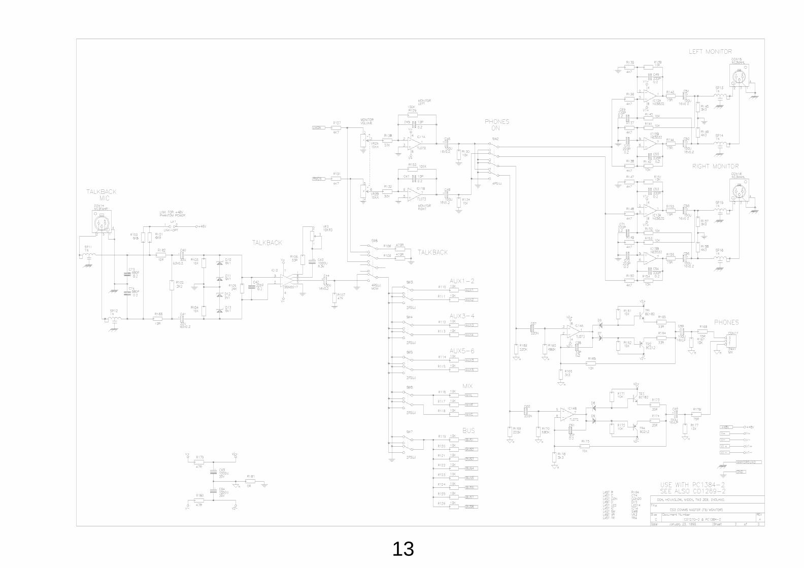
13
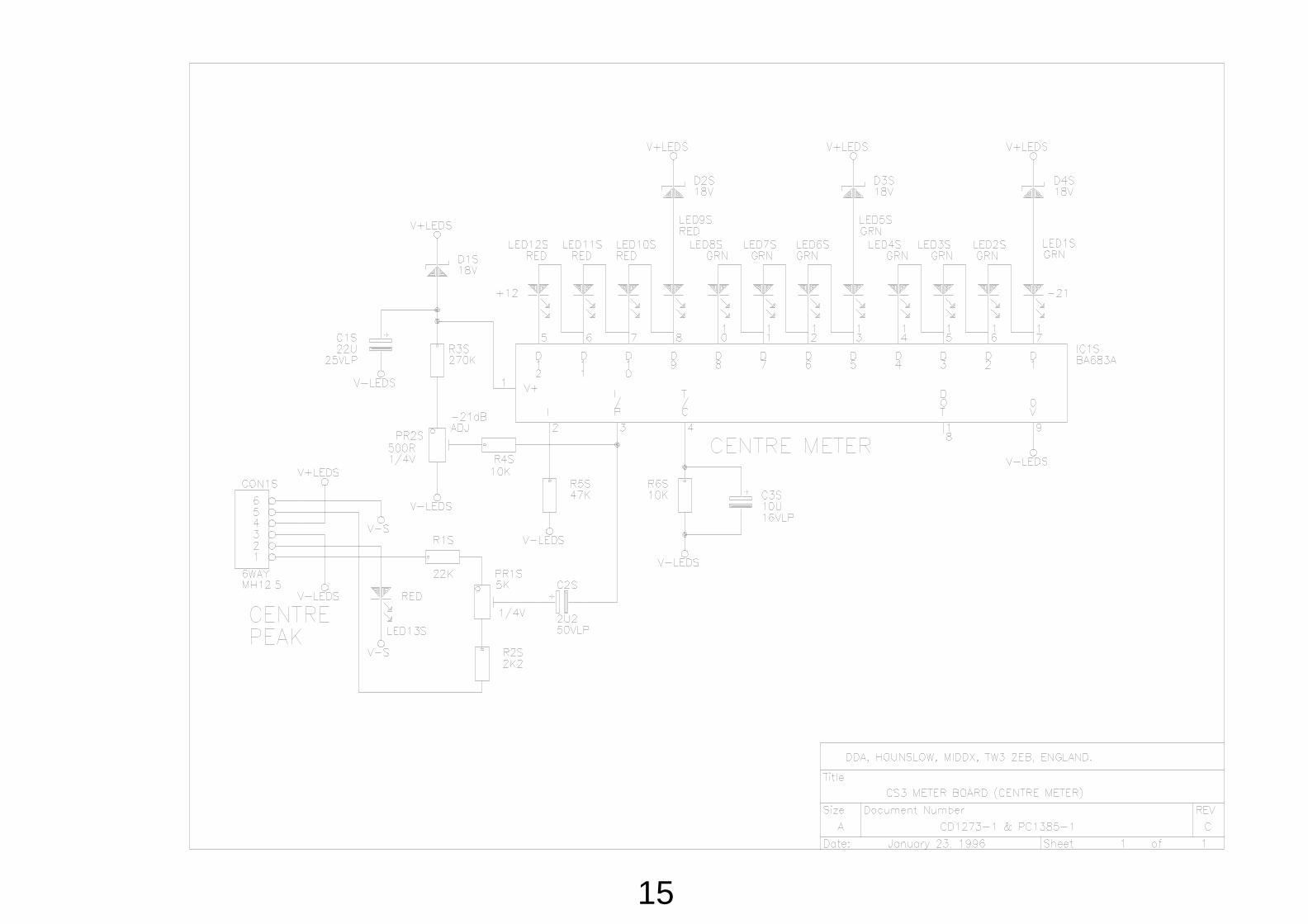
15

17

19

20