Embed Size (px)
Citation preview

Page 1 of 31
CS5000 Users Manual
Intercomp Co.
3839 County Road 116
Medina MN 55340 U.S.A.
(763)-476-2531
1-800-328-3336
Fax: 763-476-2613 www.intercompcompany.com
Manual#: 700008-V

CS5000, Users Rev V, January, 2008
2
Table of Contents
INTRODUCTION ............................................................................................................................................................ 3
SPECIFICATIONS .............................................................................................................................................................. 3 Controls..................................................................................................................................................................... 3 Electrical................................................................................................................................................................... 3 Performance.............................................................................................................................................................. 3 Environmental........................................................................................................................................................... 3 Physical..................................................................................................................................................................... 4 Radio......................................................................................................................................................................... 5
PARTS AND OPTIONAL EQUIPMENT................................................................................................................................. 5
OPERATIONS.................................................................................................................................................................. 7
DISPLAY (BASE) ............................................................................................................................................................. 7 Indicators .................................................................................................................................................................. 7
CONTROLS - HEAD (SCALE) ............................................................................................................................................ 7 ON............................................................................................................................................................................. 7
CONTROLS - BASE (CONTROLLER) .................................................................................................................................. 8 SETUP ........................................................................................................................................................................... 10
lb/kg Switching........................................................................................................................................................ 10 Setting time and date............................................................................................................................................... 10
POWER/BATTERIES ....................................................................................................................................................... 11
CALIBRATION.............................................................................................................................................................. 12
HOW TO TEST THE CALIBRATION ................................................................................................................................... 12 CALIBRATION SWITCH .................................................................................................................................................. 12 HOW TO CALIBRATE THE SCALE ................................................................................................................................... 13 LEGAL-FOR-TRADE SEALING ........................................................................................................................................ 16
ERROR MESSAGES ..................................................................................................................................................... 17
TROUBLESHOOTING................................................................................................................................................. 18
PARTS AND ACCESSORIES....................................................................................................................................... 20
PARTS LIST: 500 LB CAPACITY ..................................................................................................................................... 21 PARTS LIST: 2K LB CAPACITY ...................................................................................................................................... 23 PARTS LIST: 5K LB, 10K LB CAPACITY......................................................................................................................... 25 PARTS LIST: 20K LB, 30K LB CAPACITY....................................................................................................................... 27
SERIAL OUTPUT.......................................................................................................................................................... 28
EXAMPLE CONNECTIONS .............................................................................................................................................. 29
HOW TO REACH INTERCOMP SERVICE.............................................................................................................. 31
"This document is the property of Intercomp Co. It contains material and information that is confidential and protected under federal and/or state trade secret, unfair competition, and copyright law. Any reproduction, use or disclosure without written permission from Intercomp Co. is prohibited".

CS5000, Users Rev V, January, 2008
3
Introduction This manual contains specifications, operation instructions, and calibration instructions for Intercomp's model CS5000 crane scale.
Specifications
Controls General: Head:
Base: On (Base remotely turns the scale head off). On/Off ,Zero, Print, Total, Display Total, Clear Total, Tare Set, Tare Display, Tare Clear.
Display: Base: 5 ½ digit LED.
Indicators: Head: Base:
power. lb/kg, Tare, Net, Gross, On-screen Motion, Total.
Electrical Batteries: (Base and Head)
8 X D-size disposable alkaline dry cells or rechargeable Nickel-Cadmium cells.
Battery life: Up to 50 hours with alkaline batteries. Approximately 20 hours on a set of fully charged Ni-Cad cells.
Resolution: 20 bit A/D delivers over 1,000,000 internal counts.
Filtering: 6 Pole, 10 Hertz low pass.
Auto off: Low battery, or after adjustable time without use or motion.
Auto-Zero: Satisfies all HB-44 requirements; selectable 0.6, 1, or 3 graduations.
Performance Accuracy: ±0.1% of applied load or ± display graduation, whichever
is greater.
Speed 2 readings / sec.
Transmitting Range Up to 500 ft / 150 meters
Environmental Humidity: 10 to 95% Non-Condensing
Temperature: Storage: -40 C to +75 C. / -40 F to +170 F.
Operating -10 C to +50 C. / +14 F to +122 F.

CS5000, Users Rev V, January, 2008
4
Physical
Capacity Graduation A
B C D Hook Eye nut
or
shackle
Approx
Weight
500 lb 250 kg
0.2 lb 0.1 kg
in:
mm:
19.3 490
3.06 77.7
1.44 35.1
1.41 35.8
C/L 3 ton S1 swivel
C/L #7 eye nut
48 lb 22 kg
2,000 lb 1,000 kg
1 lb 0.5 kg
in:
mm:
19.3 490
3.06 77.7
1.44 35.1
1.41 35.8
C/L 3 ton S1 swivel
C/L #7 eye nut
50 lb 23 kg
5,000 lb 2,500 kg
1 lb 0.5 kg
in:
mm:
22.0 558
3.06 77.7
1.82 44.5
1.69 42.9
C/L 5 ton S1 swivel
C/L #7 eye nut
58 lb 26 kg
10,000 lb 5,000 kg
2 lb 1 kg
in:
mm:
22.0 558
3.06 7.77
1.75 44.5
1.69 42.9
C/L 5 ton S1 swivel
C/L #7 eye nut
58 lb 26 kg
20,000 lb 10,000 kg
5 lb 2 kg
in:
mm:
37.15 944
6.25 159
2.60 65.8
2.41 61.2
C/L 10 ton S1 swivel
C/L # 11 eye nut
97 lb 44 kg
30,000 lb 15,000 kg
10 lb 5 kg
in:
mm:
39.15 994
6.25 159
3.00 76.2
3.19 81.3
The dimensions below are top to bottom shackle, eye to eye on 25-50 ton / 12.5 –25 metric ton models C/L 15 ton
S1 swivel C/L # 11 eye nut
122 lb 55 kg
50,000 lb 25,000 kg
10 lb 5 kg
in:
mm:
43.5 1105
6.00 152
3.66 93.0
3.62 92.0
17.0 432
C/L 25 ton S1 swivel
C/L 40 ton #2140
220 lb 100 kg
70,000 lb 35,000 kg
20 lb 10 kg
in:
mm:
48.6 1234
6.00 152
4.56 116
3.75 92.3
17.0 432
C/L 35 ton S1 swivel
C/L 40 ton #2140
248 lb 113 kg
100,000 lb 50,00 kg
20 lb 10 kg
in:
mm:
56.0 1422
7.75 197
5.06 129
4.25 108
18.0 457
C/L 45 ton S1 swivel
C/L 50 ton #2140
392 lb 178 kg
*
*
*
*
CS5000, Users Rev V, January, 2008
5
Radio Radio frequency (US/Canada)
2.4 GHz, FHSS, 50 mW output power
License requirements None. Pre-approved US/FCC, CAN/IC, EUR/EN
Range 200’ / 60m indoor, 300’ / 90m line of sight
Parts and Optional Equipment
Oversized top lifting eye (100744) This part is applicable to 500 lb - 10,000 lb capacity models.
Oversized top shackle (100745) This part is applicable to 20,000 lb and 30,000 lb capacity models.
Oversized top shackle (100746) This part is applicable to 50,000 lb and 70,000 lb capacity models.
Oversized top shackle (100747) This part is applicable to 100,000 lb capacity models.
Anti heat shield (100720)
Bottom plate with standard hook rated for 0° - 1000°.
Medium anti heat shield (100670)
1000° - 1500° protection. Includes oversized hook and custom swivel.
Extreme anti heat shield (100671)
1500° - 2500° protection. Includes oversized hook and custom swivel.
Remote load cell input and summing (100724) Load cell input with electronic summing board. An external load cell can be connected to the CS5000. The scale averages the signals from the 2 load cell outputs.
RS232 Serial data output (100721) The CS5000 has an RS232 connection so the unit may communicate with a printer or computer.
LED Display on crane unit (100725) Optional LED (light emitting diode) display on the head. An LED display is fully readable in pitch-dark lighting situations.
WARNING: To satisfy FCC RF exposure requirements for mobile
type transmitting devices, a separation distance of 20cm or more should be maintained between the antenna of this device and persons during operation, with the exception of hands, wrist, feet, and ankles. To ensure compliance, operations at closer distance than this is prohibited.
!

CS5000, Users Rev V, January, 2008
6
LCD Display on crane unit (100726) Optional LCD (liquid crystal display) display on the head.
Anti-magnetic shielding (100722) Provides protection from high magnetic fields.
Battery pack and 120V external charger (100730) Rechargeable Ni-Cad battery pack (8 D-cells) with 120V external charger. Standard power uses 8 disposable alkaline dry cells.
Battery pack and 220V external charger (100731) Rechargeable Ni-Cad battery pack (8 D-cells) with 220V external charger. Standard power uses 8 disposable alkaline dry cells.
Battery pack, Ni-Cad (100733) D size rechargeable battery pack (qty: 8).
Direct Power on crane unit, 120V (100723) This option allows the CS5000 to use 120V power instead of batteries.
Direct Power on crane unit, 220V (100727) This option allows the CS5000 to use 220V power instead of batteries.

CS5000, Users Rev V, January, 2008
7
Operations
Display (Base)
kg Optional: displays ‘1’ or blank Gross
Total Net
lb Tare
Indicators
kg: Indicates the scale is weighing in kilograms. When lit, the scale is in kg mode. Press TOTAL DISPLAY and TARE DISPLAY together to toggle units.
Total: Indicates that the current number displayed is the total. The net indicator
will also be lit to represent that the total totalizes the net weights.
lb: Indicates the scale is weighing in pounds. When lit, the scale is in lb mode. Press TOTAL DISPLAY and TARE DISPLAY together to toggle units.
Gross: This indicator is lit when the display represents that the gross weight is being displayed.
Net: This indicator is lit when a tare value is set and the weight shown is the calculated net weight.
Tare: This indicator is lit while the tare weight is being displayed.
Controls - Head (scale)
ON Press this button to turn the scale on.

CS5000, Users Rev V, January, 2008
8
Controls - Base (controller)
ON/OFF Press this button to turn the base unit on. The scale tests itself, then displays
“--------------------“ or “HO-00HO-00HO-00HO-00”. When a weight is received from the scale head it will be displayed. Press this button again to turn the scale off. The head will turn off automatically.
PRINT Pressing this key will output an RS-232 signal containing the Gross, Net, Tare, total weight, and the time and date. Note: The print key will only function when there is no motion. Also see the ‘Serial Output' section in this manual.
ZERO Tells the scale to display a zero weight. This button is used any time the scale shows a non-zero value with no weight on the hook. If you press ZERO with weight on the hook, that weight becomes the zero condition for the scale. This can be useful to cancel the weight of any weighing fixtures, such as containers, chains or cables. When this weight is removed, a negative weight shows until the system is zeroed again.
NOTES: When ZERO is pressed, the CS5000 will display "--------------------" until a stable reading is taken. If there is continuous motion for more than 20 or 30 seconds, the zero command will be rejected and the scale will return to normal weighing. The scale contains a feature called Auto Zero Tracking (AZT), which corrects for slight zero changes during normal operation. If small weights are added slowly, the scale could zero them off.
TARE Use this button to read a tare weight into memory. This tare weight will be subtracted from a gross weight, giving you the net weight. This is useful for canceling the weight of a container used in weighing. A segment on the right side of the display shows that the net weight is being calculated.
NOTE: When TARE is pressed, the CS5000 will display "--------------------" until a stable reading is taken. If there is continuous motion for more than 20 or 30 seconds, the tare command will be rejected and the scale will return to normal weighing.
CS5000, Users Rev V, January, 2008
9
TARE DISPLAY You may press the TARE DISPLAY button to display the tare weight. Pressing the TARE DISPLAY button a second time will return to the gross or net display.
TARE CLEAR This button is used to clear a stored tare weight to zero.
TOTAL By pressing this button, the current net weight is added to the total. Note: If the tare weight is zero, the net weight is equal to the gross weight.
TOTAL DISPLAY Pressing the TOTAL DISPLAY screen will switch the display to show the current total weight. Pressing the key a second time will return to normal weighing.
TOTAL CLEAR Clears the total to zero.

CS5000, Users Rev V, January, 2008
10
Setup
Use the following procedure to setup and weigh:
1: Hook CS5000 scale head onto hoist. 2: Turn on CS5000 scale head. 3: Turn on CS5000 base. 4: Hook any weighing fixtures onto CS5000 hook (chains, etc.) 5: Hook any weighing bin or platform onto CS5000 hook or fixtures. 6: Hoist into air so that it is free swinging. 7: Press ZERO on base. The CS5000 will wait for a stable zero reading. 8: Proceed with weighing.
lb/kg Switching Press the TOTAL DISPLAY and TARE DISPLAY keys together to switch lb/kg. This toggles the weighing system between pound (English) and kilogram (SI metric) units of measure. The current unit of measure is shown by the left indicators of the CS5000 base (as shown in the section Display (Base) ).
Setting time and date To set the time and date press the three keys labeled TARE, TARE DISPLAY, and TARE CLEAR together and release. The scale will then ask you to enter seven numbers representing the month, day, year, hour, minute, second, and am/pm. You increase the number by pressing the TARE DISPLAY button. When the number is set, pressing the TARE button moves on to the next number. When you have completed entry of all seven numbers press the TARE CLEAR button to exit and start the clock running. The numbers are displayed in the following format Hx-yy, were x is the number being set and yy is the value. The following chart shows the seven values and their ranges.
Display Meaning Range
H1-yyH1-yyH1-yyH1-yy Month 1-12
H2-yyH2-yyH2-yyH2-yy Day 1-31
H3-yyH3-yyH3-yyH3-yy Year 0-99
H4-yyH4-yyH4-yyH4-yy Hour 1-12
H5-yyH5-yyH5-yyH5-yy Minutes 0-59
H6-yyH6-yyH6-yyH6-yy Seconds 0-59
H7-yyH7-yyH7-yyH7-yy am/pm 0-1 (0 = am, 1 = pm)
If the year is set prior to '91 it will be displayed as 20xx.

CS5000, Users Rev V, January, 2008
11
Power/Batteries
Head: Remove the two caps in the back of the CS5000 head. Tip the old cells out.
Change the 8 ‘D’ cells, being careful to put the positive end in first (The end with the bump). Replace the battery caps.
Base: Loosen the 2 screws that latch the lid tight so the lid can be opened. Replace the 8
‘D’ cells, being careful to note the polarity indicated on the battery holders. Close lid and retighten the screws for the latches.
You may use rechargeable 8 Nickel-Cadmium 'D' cells or 8 standard alkaline 'D' cells in the CS3000.
Warning: If you have the optional charger, do not plug the charger in
while there are standard ‘D’ cells inside. This could result in damage
to the batteries and your scale.
The typical recharge time for Ni-cad cells is 16 hours. The rechargeable batteries have a life span up to 1000 cycles.

CS5000, Users Rev V, January, 2008
12
Calibration
How to test the calibration This calibration procedure should be performed annually for normal operating conditions. If the scale is dropped or damaged, or service has been performed on the scale, use this calibration check. 1. Turn on the head and the base. The display does a lamp test; during this time the
scale does a quick check of itself. Then the weighing system starts weigh mode. 2. Intercomp recommends that you allow the electronics to operate for three minutes
after first turning power on. This allows the electronics to become stable for maximum accuracy before you check the calibrations.
3. Make sure no weight is on the hook. Press the ZERO button. Press the TARE CLEAR button to clear the tare. The weight shown is zero.
4. Apply weights throughout the weighing range, and verify the correct weight (+/- 0.1%) is displayed at each step.
5. If possible apply a weight of 105% of capacity, and verify the scale shows OE on the display.
6. Remove weights and verify the display returns to zero. 7. If there is a failure to meet any of the conditions above, please refer to the Calibration
Procedure. 8. When all the conditions above are correct, the scale is operational.
Calibration Switch The calibration of the scale is protected from accidental change by a switch protected by an access plug. The access plug is located on the front of the scale head above the “ON” switch, and is covered by a calibration sticker (seal). The switch is set in the “calibration blocked” mode at the factory.
Enabling the Calibration switch First, remove the calibration sticker which covers the access plug. Using a ¼” Allen wrench, remove the access plug. Insert the Allen wrench in to the hole and press the switch once. The scale is now set to allow calibration.
How to enter a number During this routine you will be asked to enter numbers at many points. You must use the ZERO and PRINT switches to enter these numbers. The scale will show 5 digits but there are actually 6 digits because the leftmost digit is initially invisible. The active digit will be blinking. Press the ZERO key to increase the value of the blinking digit. Press the PRINT key to move the blinking digit one place to the left. When you advance to the leftmost digit, the display will initially be blank (value of 0). This display segment can be toggled between 0 and 1. When you are finished entering the number press both the ZERO and PRINT switches simultaneously to go on.

CS5000, Users Rev V, January, 2008
13
Three point span The scale has a three point calibration feature which reduces the effects on non-linearity in the load cells. This requires that you place three weights on the cell during calibration. The first weight must be greater than zero, the second greater than the first, and the final weight somewhere between the second and the capacity.
How to Calibrate the Scale There are three parameters that can be set without moving the calibration switch, followed by three more parameters and the actual calibration which require the calibration switch to be in the enabled position.
Display Parameter Note Default
EE-00EE-00EE-00EE-00 Sample Rate 1 to 64 4
EE-01EE-01EE-01EE-01 Update Rate 1 to 32 4
EE-02EE-02EE-02EE-02 Power up in kg 1=kg, 0=lb 0
Information saved
Check for calibration blocking switch
EE-03EE-03EE-03EE-03 AZT 0=off,1=0.6,2=1,3=3 2
EE-04EE-04EE-04EE-04 Canadian Specifications 0=off, 1=on 0
EE-05EE-05EE-05EE-05 Graduation 0 to 11 6
Information saved
LL-00LL-00LL-00LL-00 Zero read Enter capacity
LL-01LL-01LL-01LL-01 First weight Enter first weight
LL-02LL-02LL-02LL-02 Second weight Enter second weight
LL-03LL-03LL-03LL-03 Third weight Enter third weight
Information saved
1. Access the calibration switch and press once if you intend to calibrate. See
Calibration Switch.
2. Turn both the base and head on. Wait for scale to warm up (2-3 minutes).
3. Press ZERO and PRINT together and release to enter the calibration mode.
4. The scale displays “EE-00EE-00EE-00EE-00”. Press the ZERO and PRINT keys simultaneously. Enter the sample rate (1 to 64), ('4' is suggested, although if your readout is too jumpy, you can increase this value). The sample rate is the number of past readings that are averages together to make a reading. (Press ZERO and PRINT keys to enter this number.)

CS5000, Users Rev V, January, 2008
14
5. The scale displays “EE-01EE-01EE-01EE-01”. Press the ZERO and PRINT keys. Enter the display update rate (1 to 32), ('4' is suggested). The display update rate is the speed at which the display is updated, with 1 being the fastest. (Press the ZERO and PRINT keys to enter this number.
6. The scale displays “EE-02EE-02EE-02EE-02”. Press the ZERO and PRINT keys. Enter what unit of
measure the scale should operate in; pounds or kilograms (0 to 1). (Press the ZERO and PRINT keys to enter this number.)
Setting Units to operate in
0 pounds (lb)
1 kilograms (kg)
Note: At this point the changes you entered will be saved and the scale could be turned off if you don't wish to change the calibration.
7. The scale shows “EE-03EE-03EE-03EE-03”. Press the ZERO and PRINT keys. Enter the desired
AZT size. The AZT size is the number of graduations the auto zero tracking can remove. Note: At this point if the calibration blocking switch is not in the enabled
position, the scale will not save the new AZT value. It will instead display the “E1E1E1E1”
error message and return to normal weighing. See “Calibration switch” to
change this.
Setting AZT size
0 Off
1 0.6
2 1
3 3
8. The scale shows “EE-04EE-04EE-04EE-04”. Press the ZERO and PRINT keys. The scale shows the current Canadian specification selection. Use the following table to select the Canadian specifications setting.
Setting Canadian
Specification
0 Off
1 On
A '0' setting implies normal operation:
1: AZT size is determined by setting of EE-03EE-03EE-03EE-03. 2: Zero operates over full range of capacity. 3: Over capacity is 103% from the zero obtained at calibration. A '1' setting implies Canadian specifications are used:
1: The AZT size fixed at 0.6d regardless of EE-03EE-03EE-03EE-03 setting.

CS5000, Users Rev V, January, 2008
15
2: The IZSM (initial zero setting mechanism on power up) must be within +/- 10% of the zero obtained at calibration.
3: The push-button zero and AZSM can only operate within +/- 2% of the IZSM. 4: The overcapacity point is 103% of capacity above the IZSM.
9. The scale shows “EE-05EE-05EE-05EE-05”. Press the ZERO and PRINT keys. Enter the desired graduation. Use the following table to select a graduation value. (Press the ZERO and PRINT keys to enter this value.)
Setting Count by
in lb
Count by
in kg
0 100 50
1 50 20
2 20 10
3 10 5
4 5 2
5 2 1
6 1 0.5
7 0.5 0.2
8 0.2 0.1
9 0.1 0.05
10 0.05 0.02
11 0.02 0.01
NOTE: To meet stated accuracy statements, it is suggested that you choose your graduation setting from the table below:
If your capacity is: Set your graduation to:
500 lb / 250 kg 0.2 lb / 0.1 kg (8)
1000 lb / 250 kg 0.5 lb / 0.2 kg (7)
2,000 lb / 1,000 kg 1 lb / 0.5 kg (6)
5,000 lb / 2,500 kg 1 lb / 0.5 kg (6)
10,000 lb / 5,000 kg 2 lb / 1 kg (5)
20,000 lb / 10,000 kg 5 lb / 2 kg (4)
30,000 lb / 15,000 kg 10 lb / 5 kg (3)
50,000 lb / 25,000 kg 10 lb / 5 kg (3)
70,000 lb / 35,000 kg 20 lb / 10 kg (2)
100,000 lb / 50,000 kg 20 lb / 10 kg (2)
Note: The changes will again be saved here and the scale could be turned off if you don't wish to change the calibration.

CS5000, Users Rev V, January, 2008
16
10. The scale displays “LL-00LL-00LL-00LL-00”. Press the ZERO and PRINT keys. On the next screen enter the capacity, in the units (lb or kg) that you are calibrating in. With no weight on the hook, press the ZERO and PRINT keys to enter in this capacity. Max capacity is 99999 lbs. Special versions allow a max capacity of 199999 lbs.
11. The scale shows “LL-01LL-01LL-01LL-01”. Apply the first weight and press the ZERO and PRINT keys. On the next screen enter the weight being applied. With the weight on the hook and its exact value shown on the CS5000 screen, press the ZERO and PRINT keys to enter in the weight.
12. The scale shows “LL-02LL-02LL-02LL-02”. Apply the second weight and press the ZERO and PRINT keys. On the next screen enter the weight being applied. With the weight on the hook and its exact value shown on the CS5000 screen, press the ZERO and PRINT keys to enter in the weight.
13. The scale shows “LL-03LL-03LL-03LL-03”. Apply the final weight and press the ZERO and PRINT keys. On the next screen enter the weight being applied. With the weight on the hook and its exact value shown on the CS5000 screen, press the ZERO and PRINT keys to enter in the weight.
Finish
The new calibration information is saved.
14. Press the calibration switch ONCE to disable calibration. This will prevent accidental entry into the calibration mode. If you are unsure of whether the switch is enabled or disabled, start going thorough the calibration menu again. After the “AZT” menu item, the scale should return to normal weighing instead of saving the
AZT value and proceeding to EE-04EE-04EE-04EE-04. See the “calibration switch” section. 15. Replace the access plug which will cover the calibration switch. 16. Cover this plug with a new calibration seal (e.g. foil calibration sticker). 17. Verify the calibration. 18. Calibration complete.
Legal-for-Trade Sealing
For qualified calibration facilities: 1. After calibration push the calibration switch. The calibration switch is located on the
upper right hand corner on the backside (side with battery caps) of the scale. 2. Verify that the scale returns to normal weighing when trying to access the weight
calibration. 3. Replace the set screw that covers the cal switch. 4. Apply the protection sticker (sticker must adhere to Intercomp’s specifications).

CS5000, Users Rev V, January, 2008
17
Error Messages
[display reads “--------------------“]: The CS5000 is waiting for a stable reading to continue. This also occurs when the unit is first turned on, or after ZERO or TARE is pressed.
EE-00EE-00EE-00EE-00 EEPROM error, the scale has had it's calibration corrupted or destroyed; the scale will require recalibration.
OL-00OL-00OL-00OL-00 Zero overload, the zero has moved outside it's limit. Return the scale's load to the initial zero-set and press ZERO, or turn the unit off and then back on.
See 'Canadian specifications' (EE-04EE-04EE-04EE-04 in the 'calibration' section).
OE-00 OE-00 OE-00 OE-00 The scale is over capacity. Reduce the load applied to the scale.
OSOSOSOS Display error, the scale is unable to display the number completely.
HO-00HO-00HO-00HO-00 Head off, the scale head is turned off or the communication link between the scale head and base has otherwise failed. If both base and head are on and you get this message, try rotating or moving the base slightly. This can sometimes have a substantial effect on the signal received.
LB-00LB-00LB-00LB-00 The scale head is low in batteries. Turn the scale base off first, then replace the 8 'D' cell batteries in the head.
BLBBLBBLBBLB The batteries in the base controller require recharging or replacement
EO:EO:EO:EO: This message occurs if the scale is turned on with a load applied which is
greater than ±10% capacity. Return the scale’s load to zero. This only
occurs when Canadian specifications are turned on. See EE-04EE-04EE-04EE-04 in the ‘Calibration section’.
E1E1E1E1 Error during calibration. It is caused by either the calibration strap being disabled, or a failure in the communication link. The scale will then exit calibration mode and return to normal weighing after a few seconds. See “Calibration switch” section.

CS5000, Users Rev V, January, 2008
18
Troubleshooting
Caution: Changing some parts on the circuit board may cause a large
change in calibration while others may or may not change the calibration,
depending on the nature of the problem. The base unit contains the “MPC board” and the “GPI Display board” The head contains the “A/D board”.
Problem: base only displays “HO-00HO-00HO-00HO-00“, no communication
Fix: Check the power on the head (LED labeled POWER). If the head does have sufficient power, this is probably a communication problem. Open the base unit and locate the transceiver. If the LED lights labeled RXD Data and TXD Data are not blinking, the transceivers are not communicating. Check to make sure the base and head unit have power. Also make sure they are within range and rotate units to try to get communication.
Problem: no power, nothing on display
Fix (applies to the base and the head): If nothing can be seen on the display, there is probably no power reaching the base circuitry. Possible causes at: bad or shorted battery pack, bad switch circuit, bad voltage regulator. Power might be reaching the unit, but the power supply might be shorted by a component or PCB trace in the power supply circuitry.
Problem: random display (display usually reads “8888.8888.8888.”)
Fix: On MPC board: check crystal (Y2). If the micro-controller is not receiving the correct or any oscillation, the microprocessor is not able to function properly. Other possibilities could be bad microprocessor (U1) on MPC board or display driver (U1 & U2 on “GPI DISPLAY” board) circuitry not functioning.
Problem: low battery indication won’t turn off
Fix:
The display will show a low battery condition (“LB-00LB-00LB-00LB-00” for the head, or “BLBBLBBLBBLB” for the base controller). Check if battery power is too low. Look at the cells and charger circuit for these problems. If that is not the cause, the display driver( U1 & U2 on the “GPI DISPLAY” board) or low voltage circuitry could be bad.
CS5000, Users Rev V, January, 2008
19
Problem: rechargeable battery life has decreased
Fix: The rechargeable batteries provided by Intercomp are high quality, high capacity Ni-Cad. However, all Ni-Cad batteries can exhibit some “memory” effects if they are repeatedly discharged to a certain point before recharging. If your observed battery life has decreased significantly from its initial performance, you may want to try this battery-conditioning sequence: Fully discharge the batteries by running the
CS5000 until the display blinks “LBLBLBLB” (low battery) and keep the unit powered until the batteries are fully discharged. Following this, recharge the battery completely (typical charge time is 16 hours). This discharge/recharge cycle may need to be repeated. If this does not help, you may need to replace the Ni-Cad batteries.
Problem: scale shuts off by itself
Fix: Check the battery holder terminals. They may be bent and not making solid contact. If the scale turns off immediately after you take your finger off the button, there may be defective power circuitry or a bad keypad.
Problem: scale “locks up”
Fix: The microprocessor (U1) on the MPC board may need to be replaced. The microprocessor support circuitry could also be bad.
Problem: weights jump or drift
Fix: Try increasing the sample rate as described in the calibration section (pg. 13). Pertains to A/D board: If this does not help, the problem could be a bad load cell, defective amplifier (U5), bad A/D chip (U6), or contamination on the A/D circuit board.

CS5000, Users Rev V, January, 2008
20
Parts and Accessories
Diagram: 500 lb capacity models
See following page for parts list
CS5000, Users Rev V, January, 2008
21
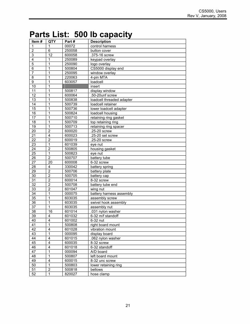
Parts List: 500 lb capacity Item # QTY Part # Description
1 1 00072 control harness
2 6 250058 button cover
3 12 600058 .375-16 screw
4 1 250089 keypad overlay
5 1 250090 logo overlay
6 1 500804 CS5000 display end
7 1 250095 window overlay
8 1 220063 4-pin MTA
9 1 603057 loadcell
10 1 insert
11 1 500817 display window
12 1 600064 .50-20unf screw
13 1 500838 loadcell threaded adapter
14 1 500739 loadcell retainer
15 1 500736 lower loadcell adapter
16 1 500824 loadcell housing
17 1 500710 retaining ring gasket
18 1 500709 top retaining ring
19 1 500713 retaining ring spacer
20 2 600020 .25-20 screw
21 4 600023 .25-20 set screw
22 2 600019 .25-20 screw
23 1 601039 eye nut
24 2 500805 housing gasket
25 1 500823 eye nut
26 2 500707 battery tube
27 20 600008 6-32 screw
28 4 330042 battery spring
29 2 500706 battery plate
30 2 500705 battery cap
31 2 600014 8-32 screw
32 2 500708 battery tube end
33 2 601047 wing nut
34 1 000075 battery harness assembly
35 1 603035 assembly screw
36 1 603035 swivel hook assembly
37 1 603035 assembly nut
38 16 601014 .031 nylon washer
39 4 601032 6-32 m/f standoff
40 4 601002 6-32 nut
41 1 500808 right board mount
42 4 601028 vibration mount
43 1 000095 display board
44 4 601015 .062 nylon washer
45 4 600035 8-32 screw
46 4 601018 6-32 standoff
47 1 000094 A/D board
48 1 500807 left board mount
49 4 600015 8-32 unc screw
50 1 500803 lower retaining ring
51 2 500818 bellows
52 1 820027 hose clamp

CS5000, Users Rev V, January, 2008
22
Diagram: 2K lb capacity models
Please see following page for parts table

CS5000, Users Rev V, January, 2008
23
Parts List: 2K lb capacity Item # QTY Part # Description
1 1 00072 control harness
2 6 250058 button cover
3 12 600058 .375-16 screw
4 1 250089 keypad overlay
5 1 250090 logo overlay
6 1 500804 CS5000 display end
7 1 250095 window overlay
8 1 220063 4-pin MTA
9 4 600023 .25-20 set screw
10 1 000062 loadcell (2K capacity CS5000)
11 1 insert
12 1 500817 display window
13 1 500838 loadcell threaded adapter
14 1 500739 loadcell retainer
15 1 500824 loadcell housing
16 1 500710 retaining ring gasket
17 1 500709 top retaining ring
18 1 500713 retaining ring spacer
19 2 600020 .25-20 screw
20 2 600019 .25-20 screw
21 1 601039 eye nut
22 2 500805 housing gasket
23 1 500823 eye nut
24 2 500707 battery tube
25 20 600008 6-32 screw
26 4 330042 battery spring
27 2 500706 battery plate
28 2 500705 battery cap
29 2 600014 8-32 screw
30 2 500708 battery tube end
31 2 601047 wing nut
32 1 000075 battery harness assembly
33 1 603035 assembly screw
34 1 603035 swivel hook assembly
35 1 603035 assembly nut
36 16 601014 .031 nylon washer
37 4 601032 6-32 m/f standoff
38 4 601002 6-32 nut
39 1 500808 right board mount
40 4 601028 vibration mount
41 1 000095 display board
42 4 601015 .062 nylon washer
43 4 600035 8-32 screw
44 4 601018 6-32 standoff
45 1 000094 A/D board
46 1 500807 left board mount
47 4 600015 8-32 unc screw
48 1 500803 lower retaining ring
49 2 500818 bellows
50 1 820027 hose clamp

CS5000, Users Rev V, January, 2008
24
Diagram: 5K lb, 10K lb capacities
See the following page for parts list

CS5000, Users Rev V, January, 2008
25
Parts List: 5K lb, 10K lb capacity Item # QTY Part # Description
1 1 00072 control harness
2 6 250058 button cover
3 12 600058 .375-16 screw
4 1 250089 keypad overlay
5 1 250090 logo overlay
6 1 500804 CS5000 display end
7 1 250095 window overlay
8 1 220063 4-pin MTA
9 4 600023 .25-20 set screw
10 1 000073 loadcell (5K and 10K capacity CS5000)
11 1 insert
12 1 500817 display window
13 1 500838 loadcell threaded adapter
14 1 500824 loadcell housing
15 1 500710 retaining ring gasket
16 1 500709 top retaining ring
17 2 600020 .25-20 screw
18 2 600019 .25-20 screw
19 1 601039 eye nut
20 2 500805 housing gasket
21 1 500823 eye nut
22 2 500707 battery tube
23 20 600008 6-32 screw
24 4 330042 battery spring
25 2 500706 battery plate
26 2 500705 battery cap
27 2 600014 8-32 screw
28 2 500708 battery tube end
29 2 601047 wing nut
30 1 000075 battery harness assembly
31 1 603035 assembly screw
32 1 603035 swivel hook assembly
33 1 603035 assembly nut
34 16 601014 .031 nylon washer
35 4 601032 6-32 m/f standoff
36 4 601002 6-32 nut
37 1 500808 right board mount
38 4 601028 vibration mount
39 1 000095 display board
40 4 601015 .062 nylon washer
41 4 600035 8-32 screw
42 4 601018 6-32 standoff
43 1 000094 A/D board
44 1 500807 left board mount
45 4 600015 8-32 unc screw
46 1 500803 lower retaining ring
47 2 500818 bellows
48 1 820027 hose clamp

CS5000, Users Rev V, January, 2008
26
Diagram: 20K lb, 30K lb, capacities
Please see following page for parts list

CS5000, Users Rev V, January, 2008
27
Parts List: 20K lb, 30K lb capacity Item # QTY Part # Description
1 1 00072 control harness
2 6 250058 button cover
3 12 600058 .375-16 screw
4 1 250089 keypad overlay
5 1 250090 logo overlay
6 1 500804 CS5000 display end
7 1 250095 window overlay
8 1 220063 4-pin MTA
9 4 600023 .25-20 set screw
10 1 000073 000063
loadcell (20K capacity CS5000) loadcell (30K capacity CS5000)
11 1 insert
12 1 500817 display window
13 1 601051 1-8 locking nut
14 1 500813 top loadcell adapter
15 2 602008 1-8 bolt
16 1 500824 loadcell housing
17 1 500710 retaining ring gasket
18 1 500709 top retaining ring
19 1 601039 eye nut
20 2 600019 .25-20 screw
21 2 600020 .25-20 screw
22 2 500805 housing gasket
23 1 500823 end plate
24 1 500946 lower loadcell adapter
25 2 500707 battery tube
26 20 600008 6-32 screw
27 4 330042 battery spring
28 2 500706 battery plate
29 2 500705 battery cap
30 2 600014 8-32 screw
31 2 500708 battery tube end
32 2 601047 wing nut
33 1 000075 battery harness assembly
34 1 603063 assembly screw
35 1 603063 swivel hook assembly
36 1 603063 assembly nut
37 16 601014 .031 nylon washer
38 4 601032 6-32 m/f standoff
39 4 601002 6-32 nut
40 1 500808 right board mount
41 4 601028 vibration mount
42 1 000095 display board
43 4 601015 .062 nylon washer
44 4 600035 8-32 screw
45 4 601018 6-32 standoff
46 1 000094 A/D board
47 1 500807 left board mount
48 4 600015 8-32 unc screw
49 1 500803 lower retaining ring
50 2 500818 bellows
51 1 820027 hose clamp

CS5000, Users Rev V, January, 2008
28
Serial Output The CS5000 base has available two communications channels, the standard interface for both is RS-232. One is equipped with a CTS (clear to send) line and designed primarily for hookup to a printer. The second channel consists of signal wires only and is designed primarily for hookup to a score board or computer. Channel 1 outputs a ticket:
Channel 2 outputs the net weight:
There is a five switch dip pak located on the main circuit board inside the base unit, it's switches have the following meanings:
Switch # On Off Function
1 1200 9600 Channel 1 baud rate
2 1200 9600 Channel 2 baud rate
3 on off Channel 1 continuous print
4 on off Channel 2 continuous print
5 on off RF interface (must be turned on, on CS5000)
The Items in bold indicate the suggested defaults.
NOTE: The RS-232 communication parameters: Fixed 8 data bits, no parity, 1 stop bit. Each channel will print under two conditions: 1: If the print key is pressed. 2: If the continuous print is turned on.
cr/lf -XXXXXX.X lb G cr/lf -XXXXXX.X lb N cr/lf -XXXXXX.X lb T cr/lf -XXXXXX.X lb TOTAL cr/lf lf lf JAN DD, 19YY HH:MM:SSam cr/lf (the 19 could be 20, and the a could be p) lf lf
-XXXXXX.X lb cr/lf
CS5000, Users Rev V, January, 2008
29
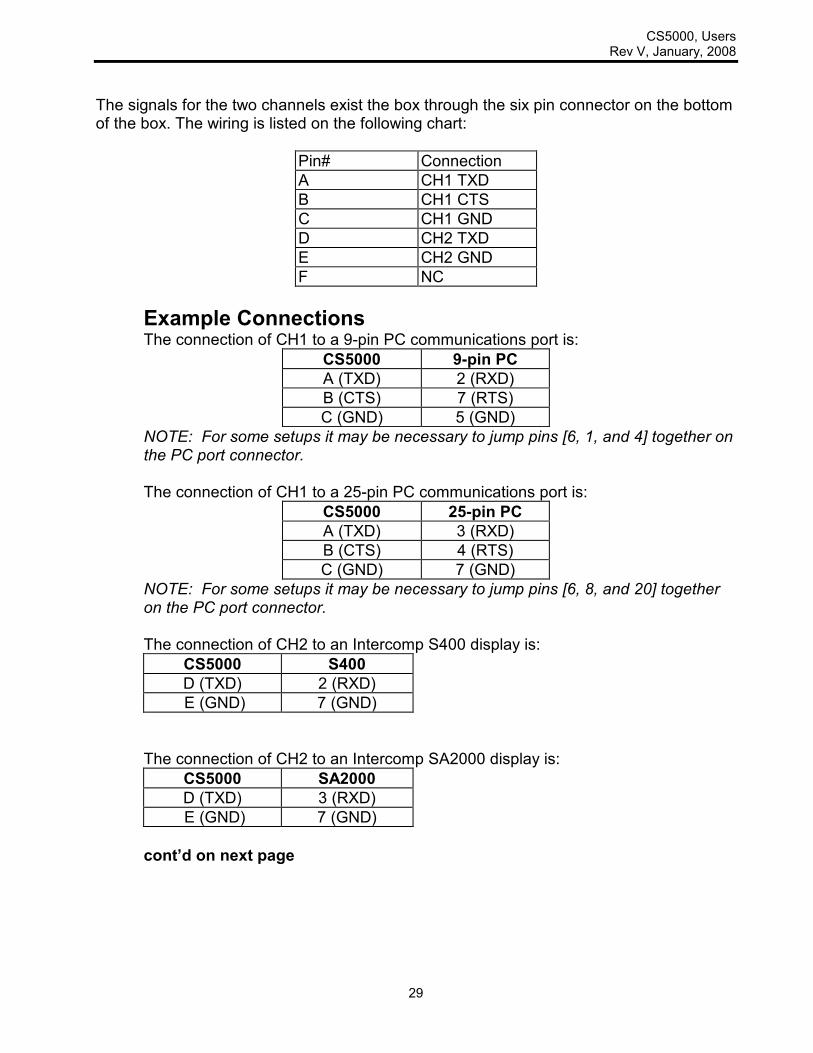
The signals for the two channels exist the box through the six pin connector on the bottom of the box. The wiring is listed on the following chart:
Pin# Connection
A CH1 TXD
B CH1 CTS
C CH1 GND
D CH2 TXD
E CH2 GND
F NC
Example Connections The connection of CH1 to a 9-pin PC communications port is:
CS5000 9-pin PC
A (TXD) 2 (RXD)
B (CTS) 7 (RTS)
C (GND) 5 (GND)
NOTE: For some setups it may be necessary to jump pins [6, 1, and 4] together on the PC port connector. The connection of CH1 to a 25-pin PC communications port is:
CS5000 25-pin PC
A (TXD) 3 (RXD)
B (CTS) 4 (RTS)
C (GND) 7 (GND)
NOTE: For some setups it may be necessary to jump pins [6, 8, and 20] together on the PC port connector. The connection of CH2 to an Intercomp S400 display is:
CS5000 S400
D (TXD) 2 (RXD)
E (GND) 7 (GND)
The connection of CH2 to an Intercomp SA2000 display is:
CS5000 SA2000
D (TXD) 3 (RXD)
E (GND) 7 (GND)
cont’d on next page

CS5000, Users Rev V, January, 2008
30
The connection of CH2 to a 9-pin PC communication port is:
CS5000 PC 9-pin
D (TXD) 2 (RXD)
E (GND) 5 (GND)
Note: For some setups it may be necessary to jump pins [6, 1, and 4] together, and pins [7 and 8] together on the PC port connector. The connection of CH2 to a 25-pin PC communication port is:
CS5000 PC 25-pin
D (TXD) 3 (RXD)
E (GND) 7 (GND)
Note: For some setups it may be necessary to jump pins [6, 8, and 20] together, and pins [4 and 5] together on the PC port connector.

CS5000, Users Rev V, January, 2008
31
How to reach Intercomp Service Things to know: 1. The service is for a CS5000 crane scale. 2. When did you purchase your scale? 3. What is your serial number? 4. Whom did you purchase the scale through? For Intercomp Service call or fax: FAX # (763)-476-2613 (763)-476-2531
1-800-328-3336 or fill out Service Support Form at: www.intercompcompany.com
Copyright Intercomp Company 2008
All rights reserved