Embed Size (px)
Citation preview
Version 4.0 22/01/2011
© 2011 www.car-solutions.com support@сarsolutions.com.ua
1
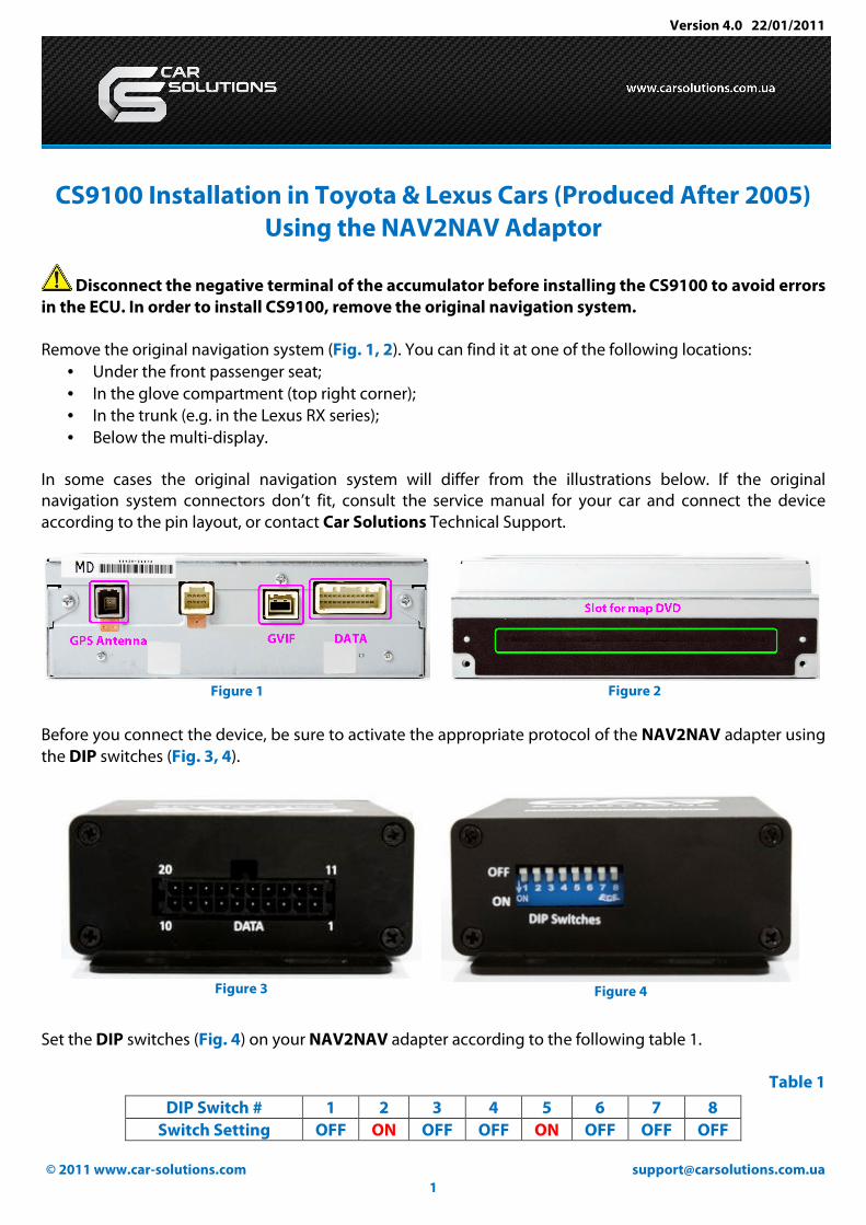
CS9100 Installation in Toyota & Lexus Cars (Produced After 2005)
Using the NAV2NAV Adaptor
Disconnect the negative terminal of the accumulator before installing the CS9100 to avoid errors
in the ECU. In order to install CS9100, remove the original navigation system.
Remove the original navigation system (Fig. 1, 2). You can find it at one of the following locations:
• Under the front passenger seat;
• In the glove compartment (top right corner);
• In the trunk (e.g. in the Lexus RX series);
• Below the multi-display.
In some cases the original navigation system will differ from the illustrations below. If the original
navigation system connectors don’t fit, consult the service manual for your car and connect the device
according to the pin layout, or contact Car Solutions Technical Support.
Figure 1
Figure 2
Before you connect the device, be sure to activate the appropriate protocol of the NAV2NAV adapter using
the DIP switches (Fig. 3, 4).
Figure 3
Figure 4
Set the DIP switches (Fig. 4) on your NAV2NAV adapter according to the following table 1.
Table 1
DIP Switch # 1 2 3 4 5 6 7 8
Switch Setting OFF ON OFF OFF ON OFF OFF OFF

Version 4.0 22/01/2011
© 2011 www.car-solutions.com support@сarsolutions.com.ua
2
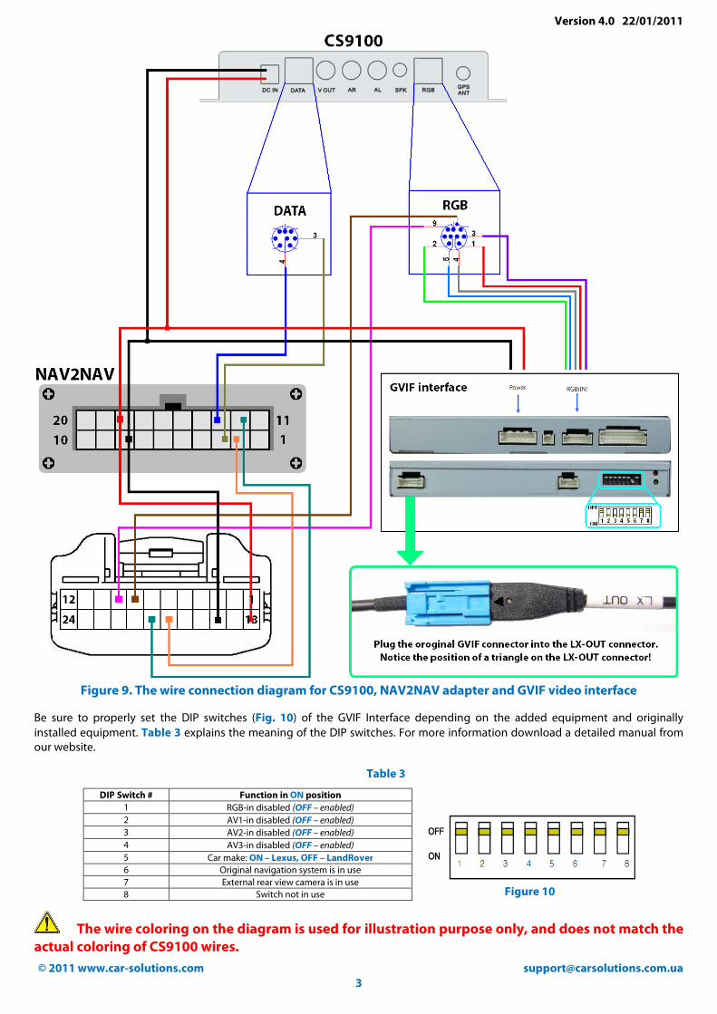
Connect the CS9100 navigation system to the NAV2NAV adapter (Fig. 3), to the GVIF interface, and to the
original navigation system connectors’ wiring* (Fig. 5), according to Table 2 or the connection diagram
(Fig. 9).
Figure 5
Wire numbers of the original navigation system connectors.
Table 2
Figure 6
Figure 7 Figure 8
Figures 6, 7, 8
illustrate the pin
layout of the RGB,
DATA, and DC IN
connectors of
CS9100. Connectors
are shown from the
side where wires are
attached.
Contact
purpose
GVIF interface
(not included in
CS9100 package)
Original
navigation
system connector
(Fig. 5)
NAV2NAV
adaptor
connector
(Fig. 3)
CS9100 connectors
(Fig. 6, 7, 8)
Tx (from
CS9100) 3 3 (Fig. 7) White
Rx (from
CS9100) 13 4 (Fig. 7) Brown
LAN Tx- 18 2
LAN Tx+ 19 12
ACC Red wire (Power) 13 18 4 (Fig. 8) Red
GND Black wire (Power) 15 8 2 (Fig. 8) Black
AUX+ 9 9 (Fig. 6) Brown
AUX- 8 Shield (Fig. 6) Black
RED Red wire (RGB IN) 1 (Fig. 6) Pink
GREEN Green wire (RGB IN) 2 (Fig. 6) Green
BLUE Blue wire (RGB IN) 5 (Fig. 6) Yellow
SYNCHRO White wire (RGB IN) 4 (Fig. 6) Gray
VGND Black wire (RGB IN) 3 (Fig. 6) Black
Version 4.0 22/01/2011
© 2011 www.car-solutions.com support@сarsolutions.com.ua
3
Figure 9. The wire connection diagram for CS9100, NAV2NAV adapter and GVIF video interface
Be sure to properly set the DIP switches (Fig. 10) of the GVIF Interface depending on the added equipment and originally
installed equipment. Table 3 explains the meaning of the DIP switches. For more information download a detailed manual from
our website.
Table 3
DIP Switch # Function in ON position
1 RGB-in disabled (OFF – enabled)
2 AV1-in disabled (OFF – enabled)
3 AV2-in disabled (OFF – enabled)
4 AV3-in disabled (OFF – enabled)
5 Car make: ON – Lexus, OFF – LandRover
6 Original navigation system is in use
7 External rear view camera is in use
8 Switch not in use
Figure 10
The wire coloring on the diagram is used for illustration purpose only, and does not match the
actual coloring of CS9100 wires.

Version 4.0 22/01/2011
© 2011 www.car-solutions.com support@сarsolutions.com.ua
4
How to install the GPS antenna
Removal of the original navigation system allows you to connect CS9100 to the car’s original GPS antenna.
The best way to do this is to desolder the plastic socket (Fig. 11) from the original wiring and solder a 10cm
coaxial cable fitted with a SMA Male connector (Fig. 12) with the wiring. The CS9100 navigation system is
fully compatible with the original antenna in all specifications.
Figure 9
Figure 10
On the other hand, you can use CS9100 with the GPS antenna that comes with it. For better signal pickup,
install the new GPS antenna in the rear spoiler (Fig. 13) (cable length allows for such installation). If there is
no rear spoiler, a fin-shaped antenna (Fig.14) can be used (it is not included with CS9100). You can also
install the CS9100 antenna (Fig. 15) under the windshield, over or under the plastic panel (Fig. 13).
Figure 11
Figure 12
Figure 13
When installing the GPS antenna in a concealed position, make sure there is no metal above it.
Installed the GPS antenna with the magnetic base down. (Fig. 15).
If your windshield and windows are made of thermal glass, install the GPS antenna on the roof or rear
spoiler.
Version 4.0 22/01/2011
© 2011 www.car-solutions.com support@сarsolutions.com.ua
5
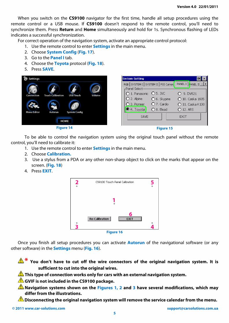
When you switch on the CS9100 navigator for the first time, handle all setup procedures using the
remote control or a USB mouse. If CS9100 doesn’t respond to the remote control, you’ll need to
synchronize them. Press Return and Home simultaneously and hold for 1s. Synchronous flashing of LEDs
indicates a successful synchronization.
For correct operation of the navigation system, activate an appropriate control protocol:
1. Use the remote control to enter Settings in the main menu.
2. Choose System Config (Fig. 17).
3. Go to the Panel I tab.
4. Choose the Toyota protocol (Fig. 18).
5. Press SAVE.
Figure 14
Figure 15
To be able to control the navigation system using the original touch panel without the remote
control, you’ll need to calibrate it:
1. Use the remote control to enter Settings in the main menu.
2. Choose Calibration.
3. Use a stylus from a PDA or any other non-sharp object to click on the marks that appear on the
screen. (Fig. 18)
4. Press EXIT.
Figure 16
Once you finish all setup procedures you can activate Autorun of the navigational software (or any
other software) in the Settings menu (Fig. 16).
* You don’t have to cut off the wire connectors of the original navigation system. It is
sufficient to cut into the original wires.
This type of connection works only for cars with an external navigation system.
GVIF is not included in the CS9100 package.
Navigation systems shown on the Figures 1, 2 and 3 have several modifications, which may
differ from the illustrations.
Disconnecting the original navigation system will remove the service calendar from the menu.