Embed Size (px)
Citation preview
CSc 466/566
Computer Security
17 : Network Security — IntroductionVersion: 2014/11/04 15:00:42
Department of Computer ScienceUniversity of Arizona
Copyright c© 2014 Christian Collberg
Christian Collberg
1/87
Outline
1 IntroductionInternet Protocol LayersPacketsNetwork Security Issues
2 The Link LayerHubs and SwitchesEthernet FramesARP Spoofing
3 The Network LayerICPMIP Spoofing
4 The Transport LayerTCP Session Hijacking
5 Denial-of-ServiceICPM AttacksSYN Flood Attacks
6 SummaryIntroduction 2/87
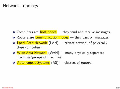
Network Topology
Computers are host nodes — they send and receive messages.
Routers are communication nodes — they pass on messages.
Local Area Network (LAN) — private network of physicallyclose computers.
Wide Area Network (WAN) — many physically separatedmachines/groups of machines.
Autonomous Systems (AS) — clusters of routers.
Introduction 3/87

Autonomoussystem
Switch
LAN
Gatewayrouter
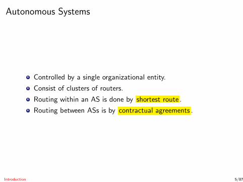
Autonomous Systems
Controlled by a single organizational entity.
Consist of clusters of routers.
Routing within an AS is done by shortest route .
Routing between ASs is by contractual agreements .
Introduction 5/87
Protocol Layers
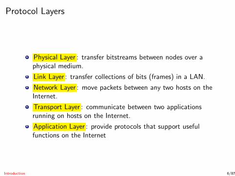
Physical Layer : transfer bitstreams between nodes over aphysical medium.
Link Layer : transfer collections of bits (frames) in a LAN.
Network Layer : move packets between any two hosts on theInternet.
Transport Layer : communicate between two applicationsrunning on hosts on the Internet.
Application Layer : provide protocols that support usefulfunctions on the Internet
Introduction 6/87
Layer
NetworkLayer
Transport
LinkLayer
ApplicationLayer
Data
FrameFooter
ApplicationData
ApplicationData
TCP DataTCPHeader
IPHeader TCP
Header
IP Data
TCP Data
ApplicationData
FrameHeader
IPHeader
Frame Data
IP Data
TCPHeader
TCP Data
Application

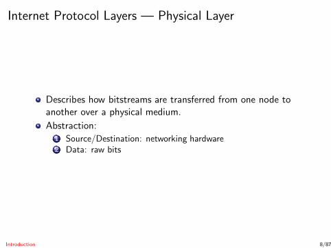
Internet Protocol Layers — Physical Layer
Describes how bitstreams are transferred from one node toanother over a physical medium.
Introduction 8/87
Internet Protocol Layers — Physical Layer
Describes how bitstreams are transferred from one node toanother over a physical medium.
Abstraction:
Introduction 8/87
Internet Protocol Layers — Physical Layer
Describes how bitstreams are transferred from one node toanother over a physical medium.
Abstraction:1 Source/Destination: networking hardware
Introduction 8/87
Internet Protocol Layers — Physical Layer
Describes how bitstreams are transferred from one node toanother over a physical medium.
Abstraction:1 Source/Destination: networking hardware2 Data: raw bits
Introduction 8/87
Internet Protocol Layers — Physical Layer
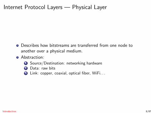
Describes how bitstreams are transferred from one node toanother over a physical medium.
Abstraction:1 Source/Destination: networking hardware2 Data: raw bits3 Link: copper, coaxial, optical fiber, WiFi. . .
Introduction 8/87
Internet Protocol Layers — Link Layer
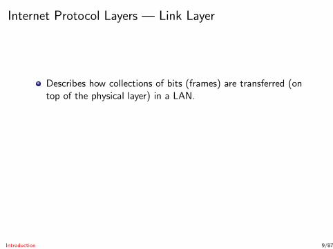
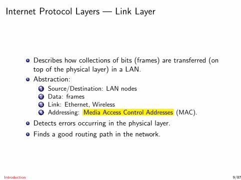
Describes how collections of bits (frames) are transferred (ontop of the physical layer) in a LAN.
Introduction 9/87

Internet Protocol Layers — Link Layer
Describes how collections of bits (frames) are transferred (ontop of the physical layer) in a LAN.
Abstraction:
Introduction 9/87
Internet Protocol Layers — Link Layer
Describes how collections of bits (frames) are transferred (ontop of the physical layer) in a LAN.
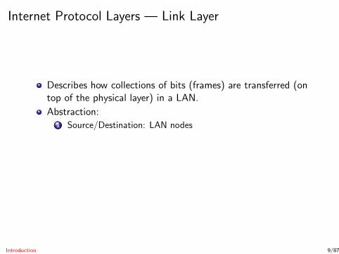
Abstraction:1 Source/Destination: LAN nodes
Introduction 9/87
Internet Protocol Layers — Link Layer
Describes how collections of bits (frames) are transferred (ontop of the physical layer) in a LAN.
Abstraction:1 Source/Destination: LAN nodes2 Data: frames
Introduction 9/87
Internet Protocol Layers — Link Layer
Describes how collections of bits (frames) are transferred (ontop of the physical layer) in a LAN.
Abstraction:1 Source/Destination: LAN nodes2 Data: frames3 Link: Ethernet, Wireless
Introduction 9/87
Internet Protocol Layers — Link Layer
Describes how collections of bits (frames) are transferred (ontop of the physical layer) in a LAN.
Abstraction:1 Source/Destination: LAN nodes2 Data: frames3 Link: Ethernet, Wireless4 Addressing: Media Access Control Addresses (MAC).
Introduction 9/87
Internet Protocol Layers — Link Layer
Describes how collections of bits (frames) are transferred (ontop of the physical layer) in a LAN.
Abstraction:1 Source/Destination: LAN nodes2 Data: frames3 Link: Ethernet, Wireless4 Addressing: Media Access Control Addresses (MAC).
Detects errors occurring in the physical layer.
Finds a good routing path in the network.
Introduction 9/87
Internet Protocol Layers — Network (Internet) Layer
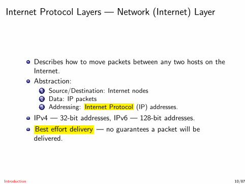
Describes how to move packets between any two hosts on theInternet.
Introduction 10/87

Internet Protocol Layers — Network (Internet) Layer
Describes how to move packets between any two hosts on theInternet.
Abstraction:
Introduction 10/87
Internet Protocol Layers — Network (Internet) Layer
Describes how to move packets between any two hosts on theInternet.
Abstraction:1 Source/Destination: Internet nodes
Introduction 10/87
Internet Protocol Layers — Network (Internet) Layer
Describes how to move packets between any two hosts on theInternet.
Abstraction:1 Source/Destination: Internet nodes2 Data: IP packets
Introduction 10/87

Internet Protocol Layers — Network (Internet) Layer
Describes how to move packets between any two hosts on theInternet.
Abstraction:1 Source/Destination: Internet nodes2 Data: IP packets3 Addressing: Internet Protocol (IP) addresses.
Introduction 10/87

Internet Protocol Layers — Network (Internet) Layer
Describes how to move packets between any two hosts on theInternet.
Abstraction:1 Source/Destination: Internet nodes2 Data: IP packets3 Addressing: Internet Protocol (IP) addresses.
IPv4 — 32-bit addresses, IPv6 — 128-bit addresses.
Introduction 10/87
Internet Protocol Layers — Network (Internet) Layer
Describes how to move packets between any two hosts on theInternet.
Abstraction:1 Source/Destination: Internet nodes2 Data: IP packets3 Addressing: Internet Protocol (IP) addresses.
IPv4 — 32-bit addresses, IPv6 — 128-bit addresses.
Best effort delivery — no guarantees a packet will bedelivered.
Introduction 10/87
Internet Protocol Layers — Transport Layer
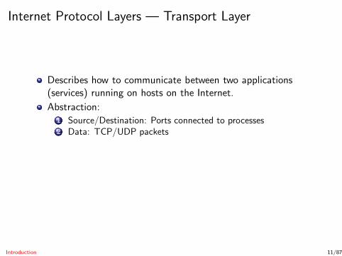
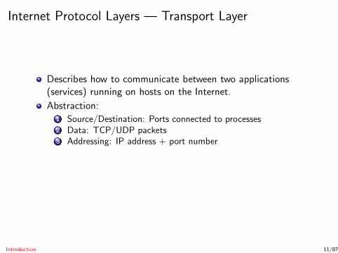
Describes how to communicate between two applications(services) running on hosts on the Internet.
Introduction 11/87
Internet Protocol Layers — Transport Layer
Describes how to communicate between two applications(services) running on hosts on the Internet.
Abstraction:
Introduction 11/87
Internet Protocol Layers — Transport Layer
Describes how to communicate between two applications(services) running on hosts on the Internet.
Abstraction:1 Source/Destination: Ports connected to processes
Introduction 11/87
Internet Protocol Layers — Transport Layer
Describes how to communicate between two applications(services) running on hosts on the Internet.
Abstraction:1 Source/Destination: Ports connected to processes2 Data: TCP/UDP packets
Introduction 11/87
Internet Protocol Layers — Transport Layer
Describes how to communicate between two applications(services) running on hosts on the Internet.
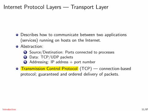
Abstraction:1 Source/Destination: Ports connected to processes2 Data: TCP/UDP packets3 Addressing: IP address + port number
Introduction 11/87
Internet Protocol Layers — Transport Layer
Describes how to communicate between two applications(services) running on hosts on the Internet.
Abstraction:1 Source/Destination: Ports connected to processes2 Data: TCP/UDP packets3 Addressing: IP address + port number
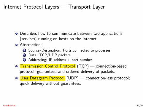
Transmission Control Protocol (TCP) — connection-basedprotocol; guaranteed and ordered delivery of packets.
Introduction 11/87
Internet Protocol Layers — Transport Layer
Describes how to communicate between two applications(services) running on hosts on the Internet.
Abstraction:1 Source/Destination: Ports connected to processes2 Data: TCP/UDP packets3 Addressing: IP address + port number
Transmission Control Protocol (TCP) — connection-basedprotocol; guaranteed and ordered delivery of packets.
User Datagram Protocol (UDP) — connection-less protocol;quick delivery without guarantees.
Introduction 11/87

Internet Protocol Layers — Application Layer
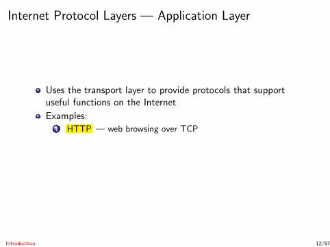
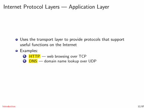
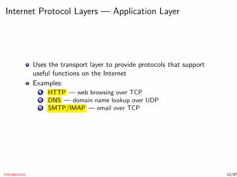
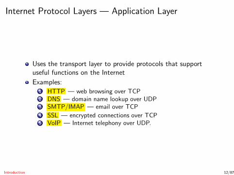
Uses the transport layer to provide protocols that supportuseful functions on the Internet
Introduction 12/87

Internet Protocol Layers — Application Layer
Uses the transport layer to provide protocols that supportuseful functions on the Internet
Examples:
Introduction 12/87
Internet Protocol Layers — Application Layer
Uses the transport layer to provide protocols that supportuseful functions on the Internet
Examples:1 HTTP — web browsing over TCP
Introduction 12/87
Internet Protocol Layers — Application Layer
Uses the transport layer to provide protocols that supportuseful functions on the Internet
Examples:1 HTTP — web browsing over TCP2 DNS — domain name lookup over UDP
Introduction 12/87
Internet Protocol Layers — Application Layer
Uses the transport layer to provide protocols that supportuseful functions on the Internet
Examples:1 HTTP — web browsing over TCP2 DNS — domain name lookup over UDP3 SMTP/IMAP — email over TCP
Introduction 12/87

Internet Protocol Layers — Application Layer
Uses the transport layer to provide protocols that supportuseful functions on the Internet
Examples:1 HTTP — web browsing over TCP2 DNS — domain name lookup over UDP3 SMTP/IMAP — email over TCP
4 SSL — encrypted connections over TCP
Introduction 12/87
Internet Protocol Layers — Application Layer
Uses the transport layer to provide protocols that supportuseful functions on the Internet
Examples:1 HTTP — web browsing over TCP2 DNS — domain name lookup over UDP3 SMTP/IMAP — email over TCP
4 SSL — encrypted connections over TCP5 VoIP — Internet telephony over UDP.
Introduction 12/87
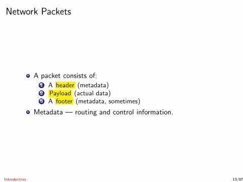
Network Packets
A packet consists of:1 A header (metadata)2 Payload (actual data)3 A footer (metadata, sometimes)
Metadata — routing and control information.
Introduction 13/87
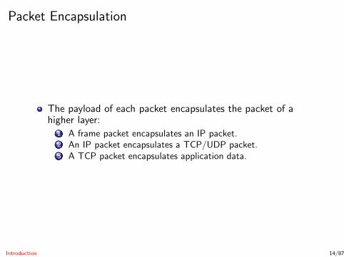
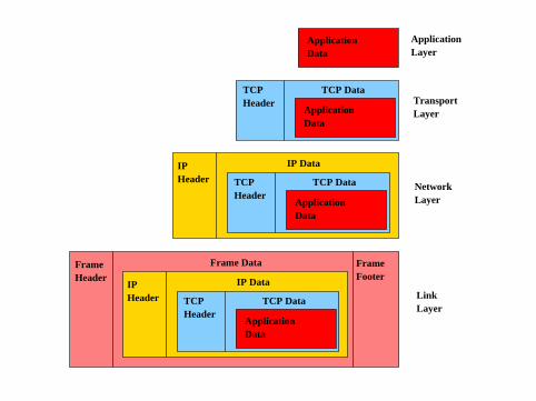
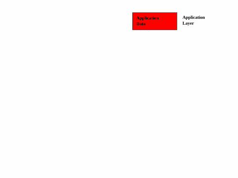
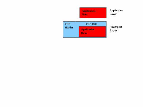
Packet Encapsulation
The payload of each packet encapsulates the packet of ahigher layer:
1 A frame packet encapsulates an IP packet.2 An IP packet encapsulates a TCP/UDP packet.3 A TCP packet encapsulates application data.
Introduction 14/87
ApplicationData
ApplicationLayer
Layer
ApplicationLayer
TCPHeader
TCP DataTransport
DataApplication
ApplicationData

Layer
ApplicationLayer
TCP DataTransportLayer
Network
IP Data
TCP Data
Data
Data
ApplicationData
TCPHeader
IPHeader
TCPHeader
Application
Application

Layer
NetworkLayer
Transport
LinkLayer
ApplicationLayer
Data
FrameFooter
ApplicationData
ApplicationData
TCP DataTCPHeader
IPHeader TCP
Header
IP Data
TCP Data
ApplicationData
FrameHeader
IPHeader
Frame Data
IP Data
TCPHeader
TCP Data
Application
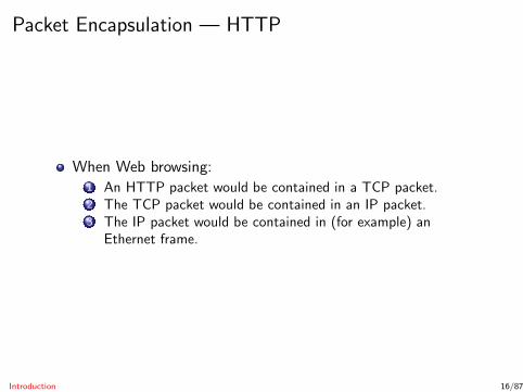
Packet Encapsulation — HTTP
When Web browsing:1 An HTTP packet would be contained in a TCP packet.2 The TCP packet would be contained in an IP packet.3 The IP packet would be contained in (for example) an
Ethernet frame.
Introduction 16/87
Networking Examples
OSI model animation: http://www.youtube.com/watch?v=fiMswfo45DQ
Animation - Networking Tutorial:http://www.youtube.com/watch?v=xV-Qq0aHs1o
Introduction 17/87

Network Security Issues
How can we keep packet data confidential?How can we maintain the integrity of packets?How can we make sure packets reach their destination?
Integrity
Confidentiality Availability
Introduction 18/87

Network Security Issues — Confidentiality
Packet data is not kept confidential.
Two solutions:1 Encrypt data at the application level (https);2 Revise lower level protocol to include encryption (IPsec).
Introduction 19/87
Network Security Issues — Integrity
Packet header/footers include simple checksums:
can detect a few communication bit errors;not cryptographically strong.
Two solutions:1 MACs at the application level;2 Revise lower level protocol.
Introduction 20/87

Network Security Issues — Availability
Denial of Service attacks:
could be just Christmas rush on amazon.com!concerted attacks.
Two solutions:1 Applications need to scale with communication requests;2 Block illegitimate requests.
Introduction 21/87
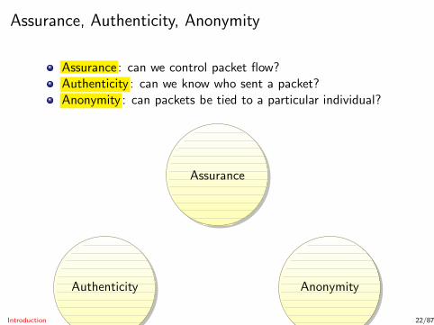
Assurance, Authenticity, Anonymity
Assurance : can we control packet flow?Authenticity : can we know who sent a packet?Anonymity : can packets be tied to a particular individual?
Assurance
Authenticity Anonymity
Introduction 22/87
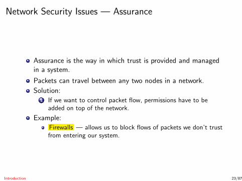
Network Security Issues — Assurance
Assurance is the way in which trust is provided and managedin a system.
Packets can travel between any two nodes in a network.
Solution:1 If we want to control packet flow, permissions have to be
added on top of the network.
Example:
Firewalls — allows us to block flows of packets we don’t trustfrom entering our system.
Introduction 23/87
Network Security Issues — Authenticity
Packets have no space for digital signatures!
IP has no concept of identity .
Two solutions:1 Add signatures at application layer;2 Revise lower level layers.
Introduction 24/87
Network Security Issues — Anonymity
No concept of identity on the Internet — anonymous bydefault!
Good for human rights worker.
Not good when we can’t identify a malicious user.
Solutions:1 Achieve higher level of anonymity by replicating processes in
many places on the network.
Introduction 25/87
Outline
1 IntroductionInternet Protocol LayersPacketsNetwork Security Issues
2 The Link LayerHubs and SwitchesEthernet FramesARP Spoofing
3 The Network LayerICPMIP Spoofing
4 The Transport LayerTCP Session Hijacking
5 Denial-of-ServiceICPM AttacksSYN Flood Attacks
6 SummaryThe Link Layer 26/87
The Link Layer
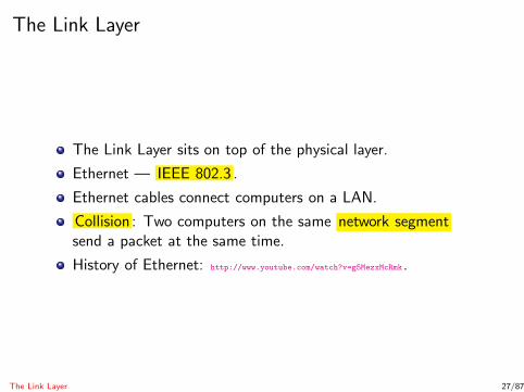
The Link Layer sits on top of the physical layer.
Ethernet — IEEE 802.3 .
Ethernet cables connect computers on a LAN.
Collision : Two computers on the same network segmentsend a packet at the same time.
History of Ethernet: http://www.youtube.com/watch?v=g5MezxMcRmk.
The Link Layer 27/87
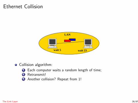
Ethernet Collision
LAN
wait 5 wait 23
Collision algorithm:1 Each computer waits a random length of time;2 Retransmit!3 Another collision? Repeat from 1!
The Link Layer 28/87

Hubs and Switches
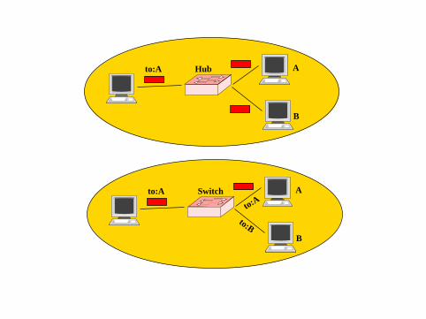
Hubs and Switches connect devices on a LAN.
Ethernet Hub :
Forward all frames to all attached devices.Lots of extra traffic: all frames are duplicated!All devices are on the same network segment, and must docollision avoidance.
Ethernet Switch :
Initially works like a hub.Over time, learns the addresses of attached devices.Eventually, only forwards a frame to the destination device.Fewer collisions.
The Link Layer 29/87
Switch
Hub
to:AA
to:A A
to:A
B
to:B
B
MAC Addresses
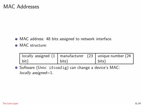
MAC address: 48 bits assigned to network interface.
MAC structure:
locally assigned (1bit)
manufacturer (23bits)
unique number (24bits)
Software (Unix: ifconfig) can change a device’s MAC:locally assigned=1.
The Link Layer 31/87

Ethernet Frame Format
Preamble (7 bytes)
Start-of-Frame delimiter (1 byte)
MAC destination (6 bytes)
MAC source (6 bytes)
Ethertype/length (2 bytes)
Payload (45-1500 bytes)
CRC-32 Checksum (4 bytes)
Interframe Gap (12 bytes)
The Link Layer 32/87
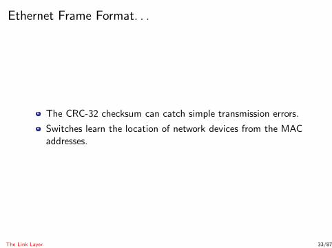
Ethernet Frame Format. . .
The CRC-32 checksum can catch simple transmission errors.
Switches learn the location of network devices from the MACaddresses.
The Link Layer 33/87

Address Resolution Protocol
Address Resolution Protocol (ARP): Find the MAC addressgiven the IP address.
Algorithm (Bob wants to know the MAC address of IPaddress A):
1 Broadcast to all network interfaces: Who has IP address A? .2 Wait for a response A is at MAC address M! from the devices
with IP address A.3 Store A ↔ M in the ARP cache .
Problem: no authentication.
The Link Layer 34/87
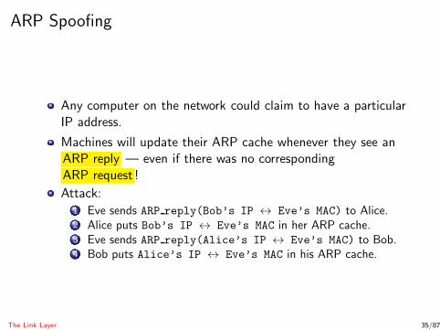
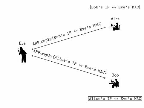
ARP Spoofing
Any computer on the network could claim to have a particularIP address.
Machines will update their ARP cache whenever they see anARP reply — even if there was no correspondingARP request !
Attack:1 Eve sends ARP reply(Bob’s IP ↔ Eve’s MAC) to Alice.2 Alice puts Bob’s IP ↔ Eve’s MAC in her ARP cache.3 Eve sends ARP reply(Alice’s IP ↔ Eve’s MAC) to Bob.4 Bob puts Alice’s IP ↔ Eve’s MAC in his ARP cache.
The Link Layer 35/87
Alice
Eve
Bob
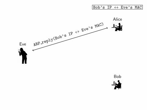
Bob’s IP ↔ Eve’s MAC
Alice
Eve
Bob
ARPrepl
y(Bob’s
IP ↔Eve’
s MAC)
Bob’s IP ↔ Eve’s MAC
Alice
Eve
Bob
Alice’s IP ↔ Eve’s MAC
ARPrepl
y(Bob’s
IP ↔Eve’
s MAC)
ARP reply(Alice’s IP↔ Eve’s MAC)
ARP Spoofing. . .
After the ARP cache poisoning all traffic between Alice andBob is routed through Eve:
1 MITM attack;2 Denial of Service attack.
The Link Layer 37/87

ARP Spoofing — Countermeasures
1 Restrict LAN access to trusted users.
The Link Layer 38/87

ARP Spoofing — Countermeasures
1 Restrict LAN access to trusted users.
2 Check for multiple occurrences of the same MAC address onthe LAN.
The Link Layer 38/87
ARP Spoofing — Countermeasures
1 Restrict LAN access to trusted users.
2 Check for multiple occurrences of the same MAC address onthe LAN.
3 Static ARP tables : the system adminstrator manually sets upthe routers’ ARP caches.
The Link Layer 38/87

ARP Spoofing — Countermeasures
1 Restrict LAN access to trusted users.
2 Check for multiple occurrences of the same MAC address onthe LAN.
3 Static ARP tables : the system adminstrator manually sets upthe routers’ ARP caches.
4 Inspect all ARP packets, detecting attempted spoofing.
The Link Layer 38/87

ARP Spoofing — Visualization
1
http://williams.comp.ncat.edu/IA_visualization_labs/security_visual_tools/wireless_attacks/wireless
The Link Layer 39/87
Outline
1 IntroductionInternet Protocol LayersPacketsNetwork Security Issues
2 The Link LayerHubs and SwitchesEthernet FramesARP Spoofing
3 The Network LayerICPMIP Spoofing
4 The Transport LayerTCP Session Hijacking
5 Denial-of-ServiceICPM AttacksSYN Flood Attacks
6 SummaryThe Network Layer 40/87
The Network (Internet) Layer
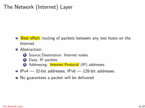
Best effort routing of packets between any two hosts on theInternet.
Abstraction:1 Source/Destination: Internet nodes2 Data: IP packets3 Addressing: Internet Protocol (IP) addresses.
IPv4 — 32-bit addresses, IPv6 — 128-bit addresses.
No guarantees a packet will be delivered.
The Network Layer 41/87

Routing Algorithm — From a Host Node
Sending a packet P from a host node N:1 If P ’s destination is on this LAN:
Use the ARP protocol to find the MAC address,
deliver directly.
2 Otherwise:
use the ARP protocol to find the MAC address of the
gateway ,
forward.
The Network Layer 42/87
Routing Algorithm — From a Router
Router — gateways and other network nodes that handlerouting of packages on the Internet.
A router typically connects two or more LANs.
Routing tables describe the next router to which a packetshould be forwarded.
The Network Layer 43/87

Router Operations
For each packet, the router decides whether to1 Drop — expired packets (TTL=0) are dropped.2 Deliver — if the packet is going to a machine on this LAN,
deliver it.3 Forward — otherwise, send to neighboring router.
TTL (time to live): a field in the IP header, decremented byeach router, used to prevent packets from living forever.
The Network Layer 44/87
Routing Table Protocols
Open Shortest Path First (OSPF) — how should packets berouted within an autonomous system?
packets should travel along shortest paths.
Border Gateway Protocol (BGP) — how should packets berouted between autonomous systems?
packets are routed based on contractual agreements.
Routing animation: http://www.youtube.com/watch?v=RbY8Hb6abbg
The Network Layer 45/87
Routing vs. Switch
Switch :
forwards packets on a single LAN.learns routes over time.
Router :
can belong to multiple LANs.uses routing tables to forward packets.
The Network Layer 46/87
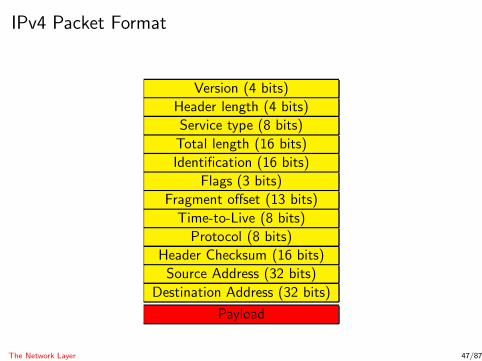
IPv4 Packet Format
Version (4 bits)
Header length (4 bits)
Service type (8 bits)
Total length (16 bits)
Identification (16 bits)
Flags (3 bits)
Fragment offset (13 bits)
Time-to-Live (8 bits)
Protocol (8 bits)
Header Checksum (16 bits)
Source Address (32 bits)
Destination Address (32 bits)
Payload
The Network Layer 47/87
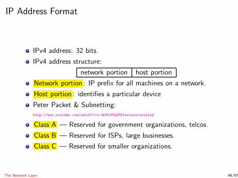
IP Address Format
IPv4 address: 32 bits.
IPv4 address structure:
network portion host portion
Network portion : IP prefix for all machines on a network.
Host portion : identifies a particular device
Peter Packet & Subnetting:http://www.youtube.com/watch?v=x-QC6l9KhQY&feature=related
Class A — Reserved for government organizations, telcos.
Class B — Reserved for ISPs, large businesses.
Class C — Reserved for smaller organizations.
The Network Layer 48/87
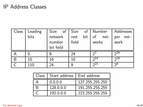
IP Address Classes
Class Leadingbits
Size ofnetworknumberbit field
Size ofrest bitfield
Numberof net-works
Addressesper net-work
A 0 8 24 27 224
B 10 16 16 214 216
C 110 24 8 221 28
Class Start address End address
A 0.0.0.0 127.255.255.255
B 128.0.0.0 191.255.255.255
C 192.0.0.0 223.255.255.255
The Network Layer 49/87
Internet Control Message Protocol
Internet Control Message Protocol (ICMP) — used fornetwork diagnostics.
ICMP messages:1 Echo request : please acknowledge receipt of packet.
The Network Layer 50/87

Internet Control Message Protocol
Internet Control Message Protocol (ICMP) — used fornetwork diagnostics.
ICMP messages:1 Echo request : please acknowledge receipt of packet.2 Echo response : packet receipt is acknowledged.
The Network Layer 50/87

Internet Control Message Protocol
Internet Control Message Protocol (ICMP) — used fornetwork diagnostics.
ICMP messages:1 Echo request : please acknowledge receipt of packet.2 Echo response : packet receipt is acknowledged.3 Time exceeded : notify that packet has expired (TTL=0).
The Network Layer 50/87

Internet Control Message Protocol
Internet Control Message Protocol (ICMP) — used fornetwork diagnostics.
ICMP messages:1 Echo request : please acknowledge receipt of packet.2 Echo response : packet receipt is acknowledged.3 Time exceeded : notify that packet has expired (TTL=0).4 Destination unreachable : notify that packet could not be
delivered.
The Network Layer 50/87

Ping Protocol
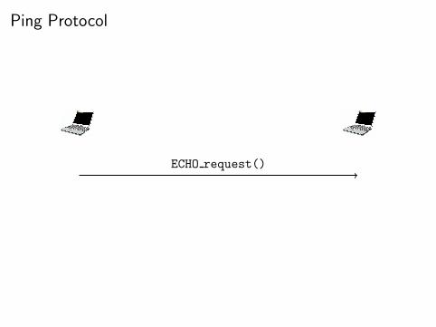
Ping Protocol
ECHO request()
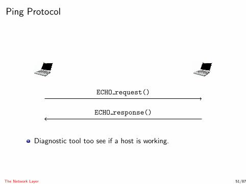
Ping Protocol
ECHO request()
ECHO response()
Diagnostic tool too see if a host is working.
The Network Layer 51/87
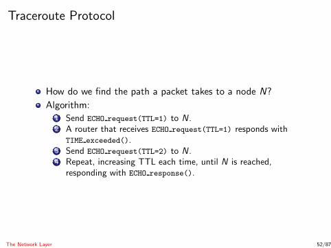
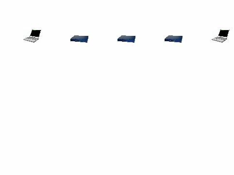
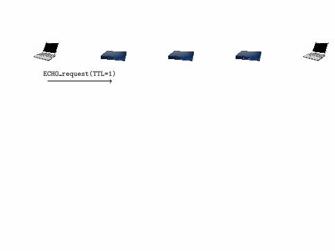
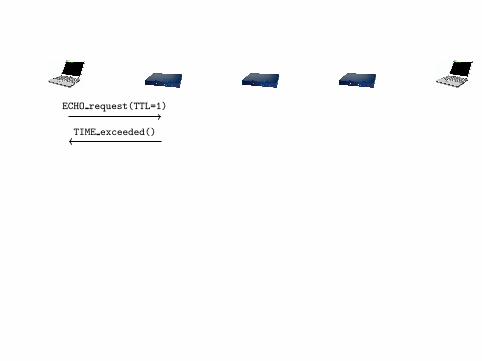
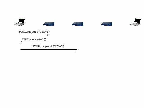
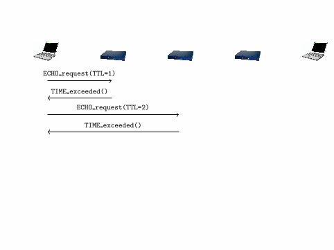
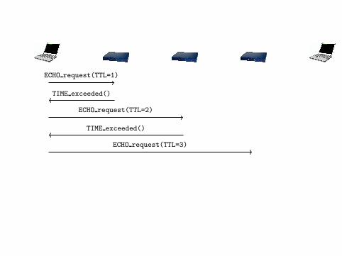
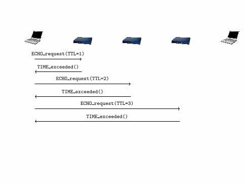
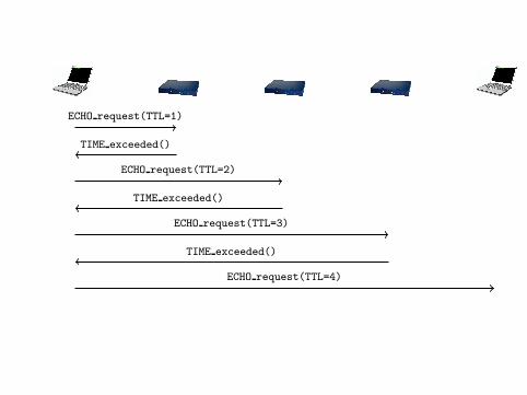
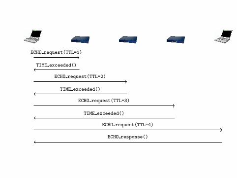
Traceroute Protocol
How do we find the path a packet takes to a node N?
Algorithm:1 Send ECHO request(TTL=1) to N .2 A router that receives ECHO request(TTL=1) responds with
TIME exceeded().3 Send ECHO request(TTL=2) to N .4 Repeat, increasing TTL each time, until N is reached,
responding with ECHO response().
The Network Layer 52/87
ECHO request(TTL=1)
ECHO request(TTL=1)
TIME exceeded()
ECHO request(TTL=1)
TIME exceeded()
ECHO request(TTL=2)
ECHO request(TTL=1)
TIME exceeded()
ECHO request(TTL=2)
TIME exceeded()
ECHO request(TTL=1)
TIME exceeded()
ECHO request(TTL=2)
TIME exceeded()
ECHO request(TTL=3)
ECHO request(TTL=1)
TIME exceeded()
ECHO request(TTL=2)
TIME exceeded()
ECHO request(TTL=3)
TIME exceeded()
ECHO request(TTL=1)
TIME exceeded()
ECHO request(TTL=2)
TIME exceeded()
ECHO request(TTL=3)
TIME exceeded()
ECHO request(TTL=4)
ECHO request(TTL=1)
TIME exceeded()
ECHO request(TTL=2)
TIME exceeded()
ECHO request(TTL=3)
TIME exceeded()
ECHO request(TTL=4)
ECHO response()
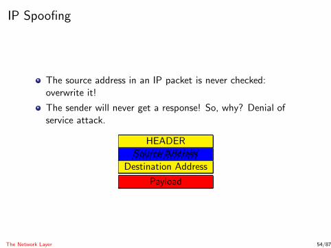
IP Spoofing
The source address in an IP packet is never checked:overwrite it!
The sender will never get a response! So, why? Denial ofservice attack.
HEADER
////////Source///////////Address
Destination Address
Payload
The Network Layer 54/87

Countermeasures to IP Spoofing
Bob’s LAN
Borderrouter Source: Bob’s Lan
Border router can block packets whose source address appearsto be from inside the subnetwork, although they come fromoutside the subnetwork.
The Network Layer 55/87

Countermeasures to IP Spoofing. . .
Bob’s LAN
Borderrouter
Source: Alice’ LAN
Border router can block outgoing packets whose sourceaddress appears to be from outside the subnetwork.
Maybe a node has been compromised by malware?
The Network Layer 56/87

Countermeasures to IP Spoofing. . .
Bob’s LAN
Block Alice!
Block Alice!
Alice
Source: EveBlock Alice!
IP Traceback — determining the origin of a packet, withoutusing the source field.
Once we know the actual source address, we can ask1 the ASs to block packets from this location.2 the ISP controlling the source address to block suspicious
machines.
The Network Layer 57/87
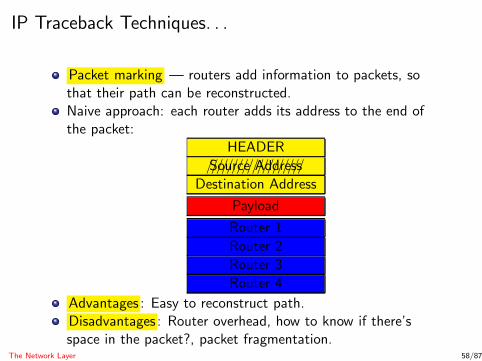
IP Traceback Techniques. . .
Packet marking — routers add information to packets, sothat their path can be reconstructed.Naive approach: each router adds its address to the end ofthe packet:
HEADER
////////Source///////////Address
Destination Address
Payload
Router 1
Router 2
Router 3
Router 4
Advantages : Easy to reconstruct path.Disadvantages : Router overhead, how to know if there’sspace in the packet?, packet fragmentation.
The Network Layer 58/87

IP Traceback Techniques — Node Sampling
Node sampling :
Only one router address can be stored in the packet.A router writes its address with probability p.
HEADER
////////Source///////////Address
Destination Address
Payload
Router address
Given enough packets, the path can be reconstructed.
The Network Layer 59/87
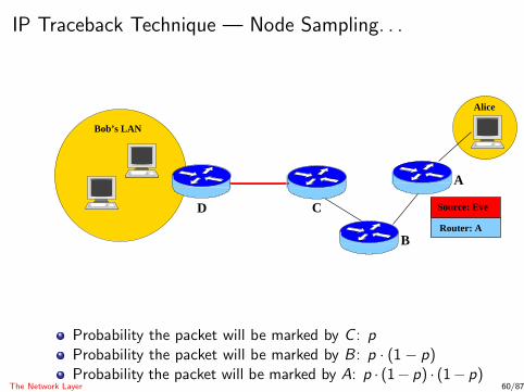
IP Traceback Technique — Node Sampling. . .
Bob’s LAN
CRouter: A
B
Source: Eve
Alice
D
A
Probability the packet will be marked by C : pProbability the packet will be marked by B : p · (1− p)Probability the packet will be marked by A: p · (1− p) · (1− p)
The Network Layer 60/87
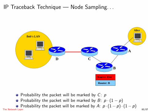
IP Traceback Technique — Node Sampling. . .
Bob’s LAN
C
Router: B
B
Source: Eve
Alice
D
A
Probability the packet will be marked by C : pProbability the packet will be marked by B : p · (1− p)Probability the packet will be marked by A: p · (1− p) · (1− p)
The Network Layer 60/87

IP Traceback Technique — Node Sampling. . .
Bob’s LAN
C
Router: B
B
Source: Eve
Alice
D
A
Probability the packet will be marked by C : pProbability the packet will be marked by B : p · (1− p)Probability the packet will be marked by A: p · (1− p) · (1− p)
The Network Layer 60/87

IP Traceback Technique — Node Sampling. . .
Bob’s LAN
C
Router: B
B
Source: Eve
Alice
D
A
Probability the packet will be marked by C : pProbability the packet will be marked by B : p · (1− p)Probability the packet will be marked by A: p · (1− p) · (1− p)
The Network Layer 60/87
IP Traceback Technique — Other Techniques
Many other techniques have been proposed.
Most not implemented — require cooperation from Internetrouters.
The Network Layer 61/87
Outline
1 IntroductionInternet Protocol LayersPacketsNetwork Security Issues
2 The Link LayerHubs and SwitchesEthernet FramesARP Spoofing
3 The Network LayerICPMIP Spoofing
4 The Transport LayerTCP Session Hijacking
5 Denial-of-ServiceICPM AttacksSYN Flood Attacks
6 SummaryThe Transport Layer 62/87
The Transport Layer
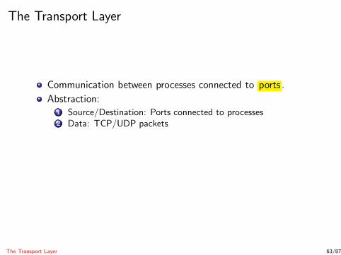
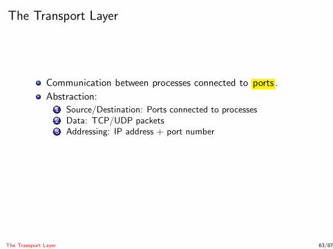
Communication between processes connected to ports .
The Transport Layer 63/87

The Transport Layer
Communication between processes connected to ports .
Abstraction:
The Transport Layer 63/87
The Transport Layer
Communication between processes connected to ports .
Abstraction:1 Source/Destination: Ports connected to processes
The Transport Layer 63/87
The Transport Layer
Communication between processes connected to ports .
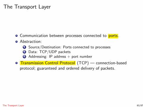
Abstraction:1 Source/Destination: Ports connected to processes2 Data: TCP/UDP packets
The Transport Layer 63/87
The Transport Layer
Communication between processes connected to ports .
Abstraction:1 Source/Destination: Ports connected to processes2 Data: TCP/UDP packets3 Addressing: IP address + port number
The Transport Layer 63/87
The Transport Layer
Communication between processes connected to ports .
Abstraction:1 Source/Destination: Ports connected to processes2 Data: TCP/UDP packets3 Addressing: IP address + port number
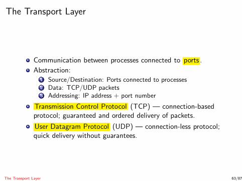
Transmission Control Protocol (TCP) — connection-basedprotocol; guaranteed and ordered delivery of packets.
The Transport Layer 63/87
The Transport Layer
Communication between processes connected to ports .
Abstraction:1 Source/Destination: Ports connected to processes2 Data: TCP/UDP packets3 Addressing: IP address + port number
Transmission Control Protocol (TCP) — connection-basedprotocol; guaranteed and ordered delivery of packets.
User Datagram Protocol (UDP) — connection-less protocol;quick delivery without guarantees.
The Transport Layer 63/87
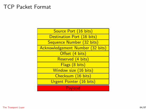
TCP Packet Format
Source Port (16 bits)
Destination Port (16 bits)
Sequence Number (32 bits)
Acknowledgement Number (32 bits)
Offset (4 bits)
Reserved (4 bits)
Flags (8 bits)
Window size (16 bits)
Checksum (16 bits)
Urgent Pointer (16 bits)
Payload
The Transport Layer 64/87

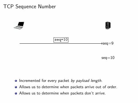
TCP Sequence Number
seq=9
Incremented for every packet by payload length.
Allows us to determine when packets arrive out of order.
Allows us to determine when packets don’t arrive.
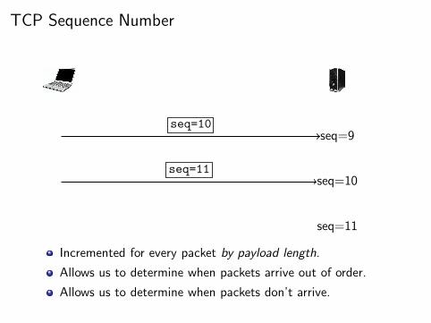
TCP Sequence Number
seq=9
seq=10
seq=10
Incremented for every packet by payload length.
Allows us to determine when packets arrive out of order.
Allows us to determine when packets don’t arrive.
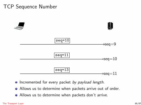
TCP Sequence Number
seq=9
seq=10
seq=11
seq=10
seq=11
Incremented for every packet by payload length.
Allows us to determine when packets arrive out of order.
Allows us to determine when packets don’t arrive.
TCP Sequence Number
seq=9
seq=10
seq=11
seq=10
seq=11
seq=13
Incremented for every packet by payload length.
Allows us to determine when packets arrive out of order.
Allows us to determine when packets don’t arrive.
The Transport Layer 65/87
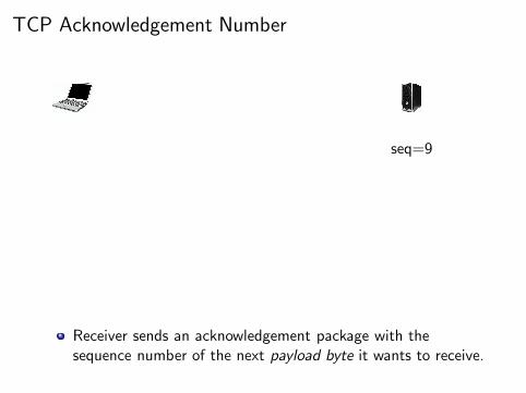
TCP Acknowledgement Number
seq=9
Receiver sends an acknowledgement package with thesequence number of the next payload byte it wants to receive.
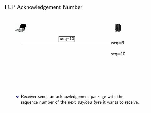
TCP Acknowledgement Number
seq=9
seq=10
seq=10
Receiver sends an acknowledgement package with thesequence number of the next payload byte it wants to receive.
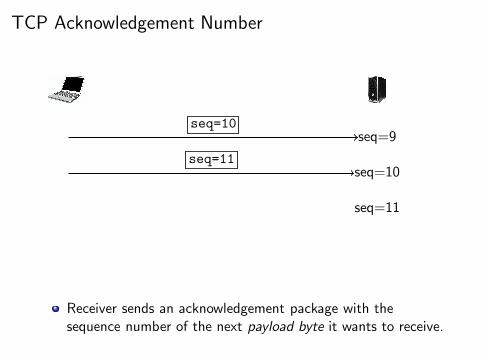
TCP Acknowledgement Number
seq=9
seq=10
seq=11
seq=10
seq=11
Receiver sends an acknowledgement package with thesequence number of the next payload byte it wants to receive.
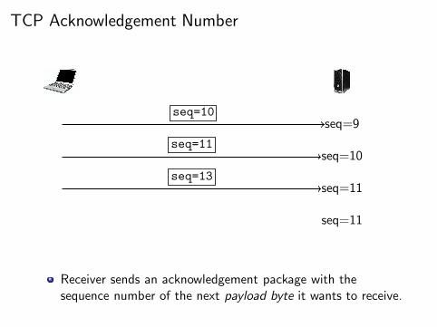
TCP Acknowledgement Number
seq=9
seq=10
seq=11
seq=11
seq=10
seq=11
seq=13
Receiver sends an acknowledgement package with thesequence number of the next payload byte it wants to receive.

TCP Acknowledgement Number
seq=9
seq=10
seq=11
seq=11
seq=12
seq=10
seq=11
seq=13
ack=12
Receiver sends an acknowledgement package with thesequence number of the next payload byte it wants to receive.

TCP Acknowledgement Number
seq=9
seq=10
seq=11
seq=11
seq=12
seq=10
seq=11
seq=13
ack=12
seq=12
Receiver sends an acknowledgement package with thesequence number of the next payload byte it wants to receive.
The Transport Layer 66/87
TCP Connections
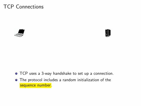
TCP uses a 3-way handshake to set up a connection.
The protocol includes a random initialization of thesequence number .
TCP Connections
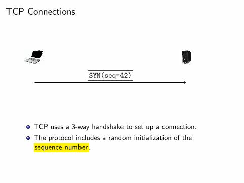
SYN(seq=42)
TCP uses a 3-way handshake to set up a connection.
The protocol includes a random initialization of thesequence number .

TCP Connections
SYN(seq=42)
SYN-ACK(seq=99,ack=42+1)
TCP uses a 3-way handshake to set up a connection.
The protocol includes a random initialization of thesequence number .
TCP Connections
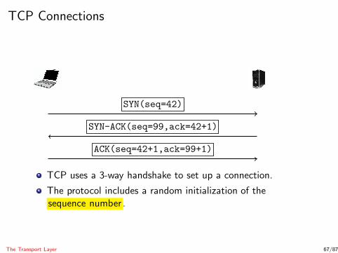
SYN(seq=42)
SYN-ACK(seq=99,ack=42+1)
ACK(seq=42+1,ack=99+1)
TCP uses a 3-way handshake to set up a connection.
The protocol includes a random initialization of thesequence number .
The Transport Layer 67/87
TCP Session Hijacking
TCP Session Hijacking — an attacker1 hijacks another user’s TCP connection;2 alters another user’s TCP connection .
The Transport Layer 68/87
TCP Sequence Prediction Attack
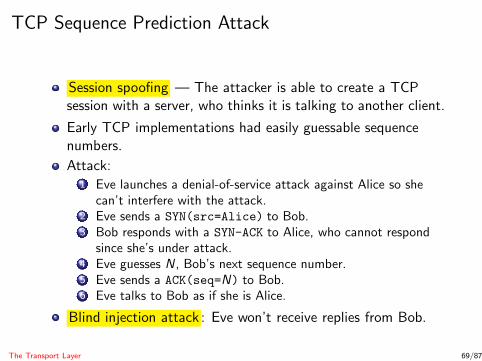
Session spoofing — The attacker is able to create a TCPsession with a server, who thinks it is talking to another client.
Early TCP implementations had easily guessable sequencenumbers.
Attack:1 Eve launches a denial-of-service attack against Alice so she
can’t interfere with the attack.2 Eve sends a SYN(src=Alice) to Bob.3 Bob responds with a SYN-ACK to Alice, who cannot respond
since she’s under attack.4 Eve guesses N , Bob’s next sequence number.5 Eve sends a ACK(seq=N) to Bob.6 Eve talks to Bob as if she is Alice.
Blind injection attack : Eve won’t receive replies from Bob.
The Transport Layer 69/87

Alice Bob
Eve
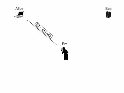
Alice Bob
Eve
DOSattack

Alice Bob
Eve
SYN(src=Alice)

Alice Bob
Eve
SYN-ACK

Alice Bob
Eve
ACK(seq=?)
Eve establishes a TCP connection with Bob, who thinks he’stalking to Alice.
Eve needs to guess the next sequence number Bob will use.
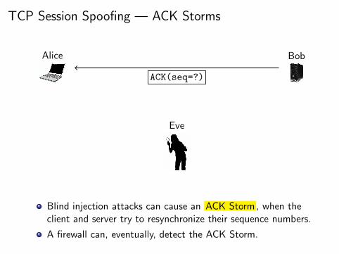
TCP Session Spoofing — ACK Storms
Alice Bob
Eve
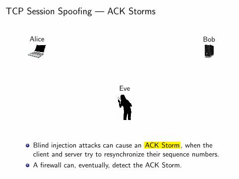
Blind injection attacks can cause an ACK Storm, when theclient and server try to resynchronize their sequence numbers.
A firewall can, eventually, detect the ACK Storm.

TCP Session Spoofing — ACK Storms
Alice Bob
Eve
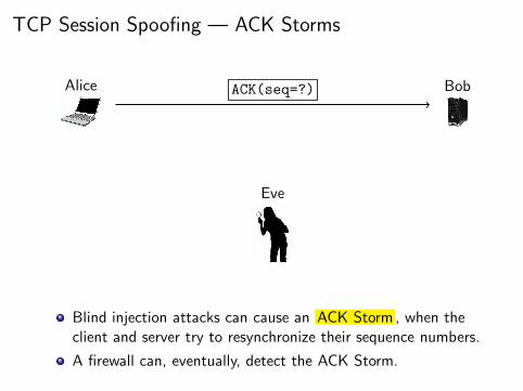
ACK(seq=?)
Blind injection attacks can cause an ACK Storm, when theclient and server try to resynchronize their sequence numbers.
A firewall can, eventually, detect the ACK Storm.

TCP Session Spoofing — ACK Storms
Alice Bob
Eve
ACK(seq=?)
Blind injection attacks can cause an ACK Storm, when theclient and server try to resynchronize their sequence numbers.
A firewall can, eventually, detect the ACK Storm.

TCP Session Spoofing — ACK Storms
Alice Bob
Eve
ACK(seq=?)
Blind injection attacks can cause an ACK Storm, when theclient and server try to resynchronize their sequence numbers.
A firewall can, eventually, detect the ACK Storm.

TCP Session Spoofing — ACK Storms
Alice Bob
Eve
ACK(seq=?)
Blind injection attacks can cause an ACK Storm, when theclient and server try to resynchronize their sequence numbers.
A firewall can, eventually, detect the ACK Storm.

TCP Session Spoofing — ACK Storms
Alice Bob
Eve
ACK(seq=?)
Blind injection attacks can cause an ACK Storm, when theclient and server try to resynchronize their sequence numbers.
A firewall can, eventually, detect the ACK Storm.

TCP Session Spoofing — ACK Storms
Alice Bob
Eve
ACK(seq=?)
Blind injection attacks can cause an ACK Storm, when theclient and server try to resynchronize their sequence numbers.
A firewall can, eventually, detect the ACK Storm.
TCP Session Spoofing — ACK Storms
Alice Bob
Eve
ACK(seq=?)
Blind injection attacks can cause an ACK Storm, when theclient and server try to resynchronize their sequence numbers.
A firewall can, eventually, detect the ACK Storm.
TCP Session Spoofing — ACK Storms
Alice Bob
Eve
ACK(seq=?)
Blind injection attacks can cause an ACK Storm, when theclient and server try to resynchronize their sequence numbers.
A firewall can, eventually, detect the ACK Storm.

TCP Session Spoofing — ACK Storms
Alice Bob
Eve
ACK(seq=?)
Blind injection attacks can cause an ACK Storm, when theclient and server try to resynchronize their sequence numbers.
A firewall can, eventually, detect the ACK Storm.

TCP Session Spoofing — ACK Storms
Alice Bob
Eve
ACK(seq=?)
Blind injection attacks can cause an ACK Storm, when theclient and server try to resynchronize their sequence numbers.
A firewall can, eventually, detect the ACK Storm.
The Transport Layer 71/87
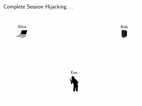
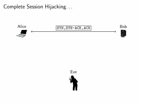
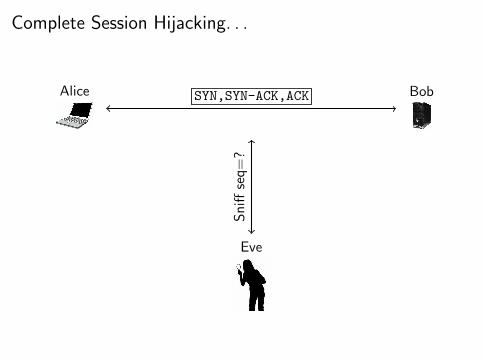
Complete Session Hijacking
Eve is on the same network segment as Alice and Bob, andpacket sniffs on them as they establish their TCP connection.
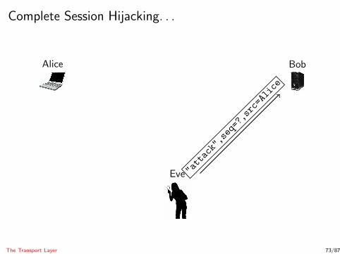
Eve guesses the next sequence number and sends a spoofedattack command to Bob, appearing to be Alice.
The Transport Layer 72/87
Complete Session Hijacking. . .
Alice Bob
Eve
Complete Session Hijacking. . .
Alice Bob
Eve
SYN,SYN-ACK,ACK
Complete Session Hijacking. . .
Alice Bob
Eve
SYN,SYN-ACK,ACK
Sniff
seq=?
Complete Session Hijacking. . .
Alice Bob
Eve "attack",seq=?,src=Alice
The Transport Layer 73/87
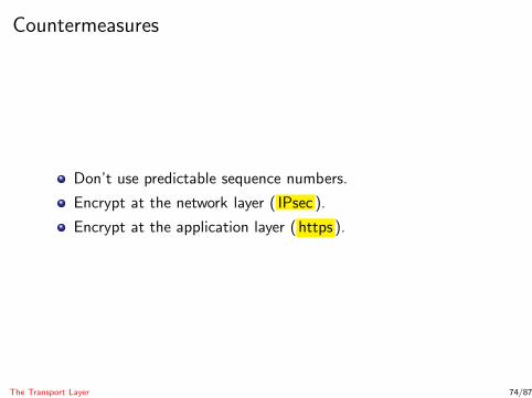
Countermeasures
Don’t use predictable sequence numbers.
Encrypt at the network layer ( IPsec ).
Encrypt at the application layer (https ).
The Transport Layer 74/87
Outline
1 IntroductionInternet Protocol LayersPacketsNetwork Security Issues
2 The Link LayerHubs and SwitchesEthernet FramesARP Spoofing
3 The Network LayerICPMIP Spoofing
4 The Transport LayerTCP Session Hijacking
5 Denial-of-ServiceICPM AttacksSYN Flood Attacks
6 SummaryDenial-of-Service 75/87
Denial-of-Service Attacks
Web servers have limited bandwidth.
Once the server has used up bandwidth/CPU, it startsdropping requests.
Denial-of-Service Attacks : Any attack that targets amachine/software’s availability.
Source addresses are spoofed to hide the attacker’s identity.
Denial-of-Service 76/87
Internet Control Message Protocol
The Internet Control Message Protocol is used for networkdiagnostics.
ICMP messages:1 Echo request : please acknowledge reciept of packet.
Denial-of-Service 77/87
Internet Control Message Protocol
The Internet Control Message Protocol is used for networkdiagnostics.
ICMP messages:1 Echo request : please acknowledge reciept of packet.2 Echo response : packet receipt is acknowledged.
Denial-of-Service 77/87
Internet Control Message Protocol
The Internet Control Message Protocol is used for networkdiagnostics.
ICMP messages:1 Echo request : please acknowledge reciept of packet.2 Echo response : packet receipt is acknowledged.3 Time exceeded : notify that packet has expired (TTL=0).
Denial-of-Service 77/87

Internet Control Message Protocol
The Internet Control Message Protocol is used for networkdiagnostics.
ICMP messages:1 Echo request : please acknowledge reciept of packet.2 Echo response : packet receipt is acknowledged.3 Time exceeded : notify that packet has expired (TTL=0).4 Destination unreachable : notify that packet could not be
delivered.
Denial-of-Service 77/87

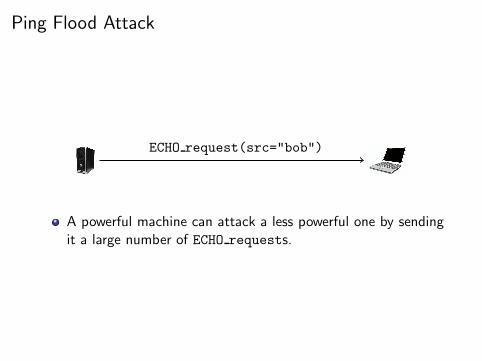
Ping Flood Attack
A powerful machine can attack a less powerful one by sendingit a large number of ECHO requests.
Ping Flood Attack
ECHO request(src="bob")
A powerful machine can attack a less powerful one by sendingit a large number of ECHO requests.

Ping Flood Attack
ECHO request(src="eve")
A powerful machine can attack a less powerful one by sendingit a large number of ECHO requests.

Ping Flood Attack
ECHO request(src="sam")
A powerful machine can attack a less powerful one by sendingit a large number of ECHO requests.
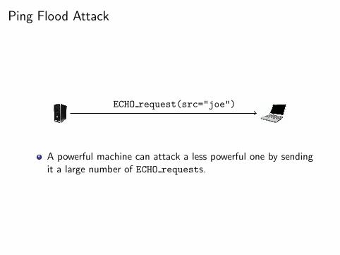
Ping Flood Attack
ECHO request(src="joe")
A powerful machine can attack a less powerful one by sendingit a large number of ECHO requests.
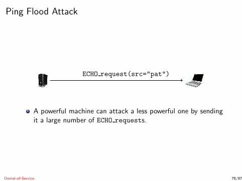
Ping Flood Attack
ECHO request(src="pat")
A powerful machine can attack a less powerful one by sendingit a large number of ECHO requests.
Denial-of-Service 78/87

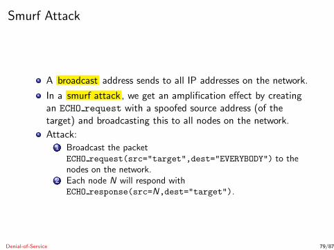
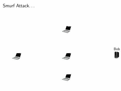
Smurf Attack
A broadcast address sends to all IP addresses on the network.
In a smurf attack , we get an amplification effect by creatingan ECHO request with a spoofed source address (of thetarget) and broadcasting this to all nodes on the network.
Attack:1 Broadcast the packet
ECHO request(src="target",dest="EVERYBODY") to thenodes on the network.
Denial-of-Service 79/87
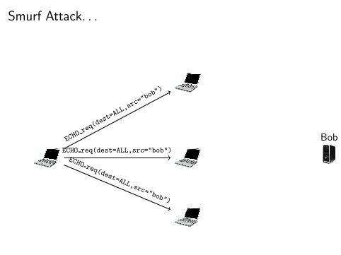
Smurf Attack
A broadcast address sends to all IP addresses on the network.
In a smurf attack , we get an amplification effect by creatingan ECHO request with a spoofed source address (of thetarget) and broadcasting this to all nodes on the network.
Attack:1 Broadcast the packet
ECHO request(src="target",dest="EVERYBODY") to thenodes on the network.
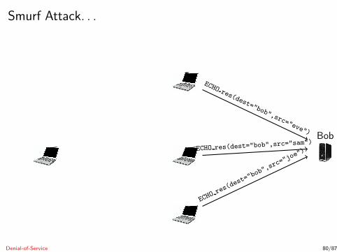
2 Each node N will respond withECHO response(src=N,dest="target").
Denial-of-Service 79/87
Smurf Attack. . .
Bob
Smurf Attack. . .
BobECHO
req(dest=ALL,src="bob")
ECHO req(dest=ALL,src="bob")ECHO req(dest=ALL,src="bob")
Smurf Attack. . .
Bob
ECHO res(dest="bob",src="eve")
ECHO res(dest="bob",src="sam")
ECHO res
(dest=
"bob",
src="j
oe")
Denial-of-Service 80/87
Smurf Attack. . .
Countermeasures:1 Make hosts and routers ignore broadcasts.2 Make servers ignore all PINGs.
Denial-of-Service 81/87

SYN Flood Attacks
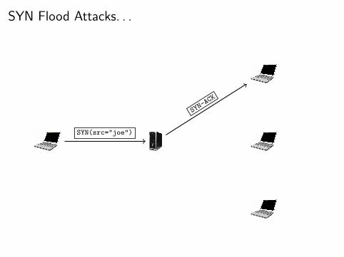
Idea: Start lots of connections to a server, but never finish theSYN/SYN-ACK/ACK sequence, causing the server’s memoryto fill up.
Attack:1 Eve sends a SYN(src="joe") packet to Alice’s server.
Denial-of-Service 82/87
SYN Flood Attacks
Idea: Start lots of connections to a server, but never finish theSYN/SYN-ACK/ACK sequence, causing the server’s memoryto fill up.
Attack:1 Eve sends a SYN(src="joe") packet to Alice’s server.2 Server responds with SYN-ACK, sent to joe.
Denial-of-Service 82/87

SYN Flood Attacks
Idea: Start lots of connections to a server, but never finish theSYN/SYN-ACK/ACK sequence, causing the server’s memoryto fill up.
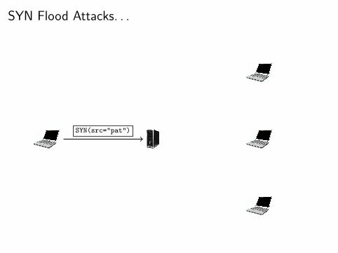
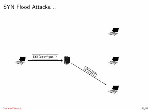
Attack:1 Eve sends a SYN(src="joe") packet to Alice’s server.2 Server responds with SYN-ACK, sent to joe.3 Eve repeats from 1.
Denial-of-Service 82/87

SYN Flood Attacks. . .

SYN Flood Attacks. . .
SYN(src="joe")
SYN Flood Attacks. . .
SYN(src="joe")
SYN-ACK

SYN Flood Attacks. . .
SYN(src="sam")

SYN Flood Attacks. . .
SYN(src="sam") SYN-ACK
SYN Flood Attacks. . .
SYN(src="pat")
SYN Flood Attacks. . .
SYN(src="pat")
SYN-ACK
Denial-of-Service 83/87

SYN Flood Attacks — Countermeasures
SYN Cookies (see the book).
Microsoft Windows:
A special queue for half-open connections.Don’t allocate resources for the TCP connection until the ACK
has been received.
Denial-of-Service 84/87
SYN Flood Attacks — Visualization
http://williams.comp.ncat.edu/IA_visualization_labs/security_visual_tools/SYNFloodDemo/index.htm
Denial-of-Service 85/87
Outline
1 IntroductionInternet Protocol LayersPacketsNetwork Security Issues
2 The Link LayerHubs and SwitchesEthernet FramesARP Spoofing
3 The Network LayerICPMIP Spoofing
4 The Transport LayerTCP Session Hijacking
5 Denial-of-ServiceICPM AttacksSYN Flood Attacks
6 SummarySummary 86/87
Readings and References
Chapter 5 in Introduction to Computer Security, by Goodrichand Tamassia.
Summary 87/87

![CSc 466/566 [5mm] Computer Security [5mm] 14 : Man-At-The ...collberg/Teaching/466-566/2012/Slide… · What is the adversary’s motivation for attacking your program? What information](https://img.pdfslide.net/doc/110x75/604802bbb51122482a591eed/csc-466566-5mm-computer-security-5mm-14-man-at-the-collbergteaching466-5662012slide.jpg)


![CSc 466/566 [5mm] Computer Security [5mm] 7 : Cryptography](https://img.pdfslide.net/doc/110x75/58a3066e1a28abd1778bb998/csc-466566-5mm-computer-security-5mm-7-cryptography-.jpg)
