Embed Size (px)
Citation preview
CSCI 4760 - Computer Networks Fall 2016
Instructor: Prof. Roberto Perdisci [email protected]
source: computer-networks-webdesign.com
These slides are adapted from the textbook slides by J.F. Kurose and K.W. Ross
Chapter 4: Network Layer
Network Layer 4-2
Chapter goals: } understand principles behind network layer services:
} network layer service models } forwarding versus routing } how a router works } routing (path selection) } dealing with scale } advanced topics: IPv6, mobility
} instantiation, implementation in the Internet
Chapter 4: Network Layer
Network Layer 4-3
} 4. 1 Introduction } 4.2 Virtual circuit and
datagram networks } 4.4 IP: Internet Protocol
} Datagram format } IPv4 addressing } ICMP } IPv6
} 4.5 Routing algorithms } Link state } Distance Vector } Hierarchical routing
} 4.6 Routing in the Internet } RIP } OSPF } BGP
} 4.7 Broadcast and multicast routing
Network layer
Network Layer 4-4
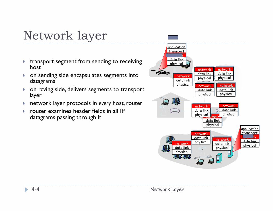
} transport segment from sending to receiving host
} on sending side encapsulates segments into datagrams
} on rcving side, delivers segments to transport layer
} network layer protocols in every host, router } router examines header fields in all IP
datagrams passing through it
application transport network data link physical
application transport network data link physical
network data link physical
network data link physical
network data link physical
network data link physical
network data link physical
network data link physical
network data link physical
network data link physical
network data link physical
network data link physical
network data link physical
Two Key Network-Layer Functions
Network Layer 4-5
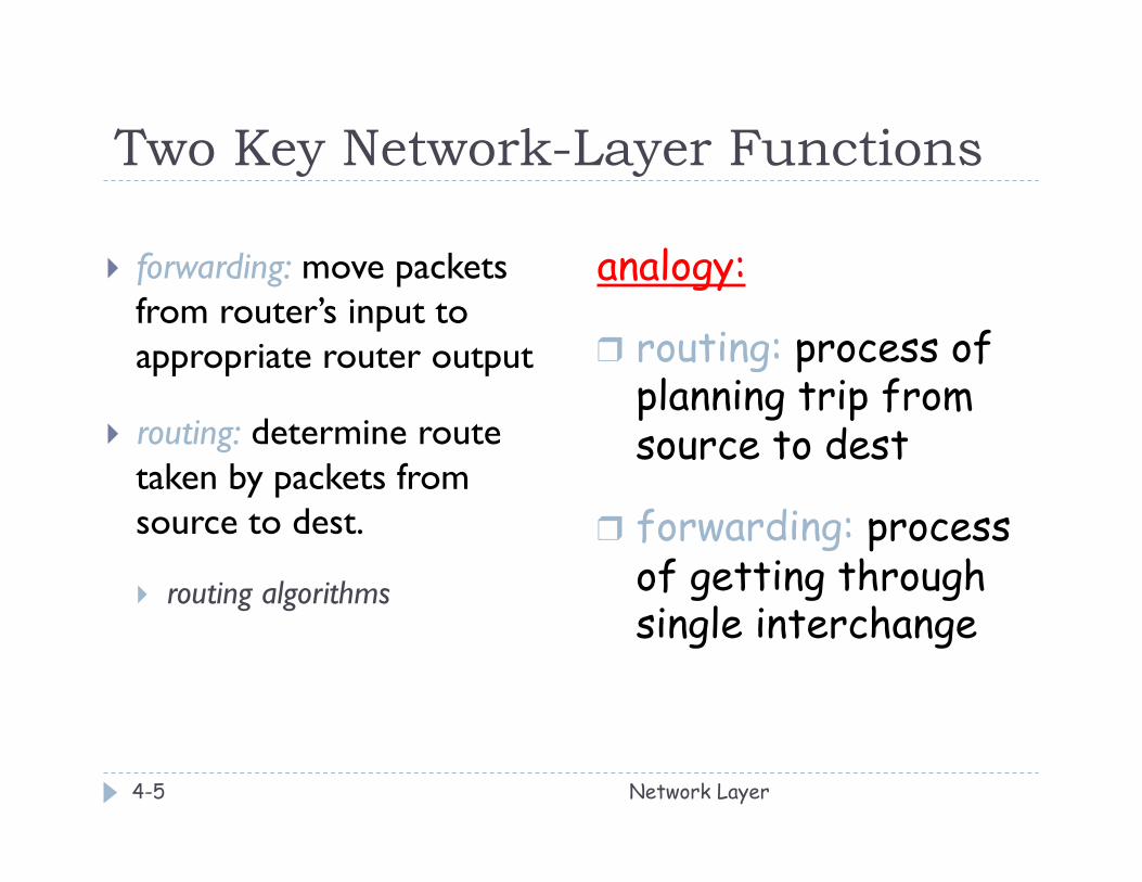
} forwarding: move packets from router’s input to appropriate router output
} routing: determine route taken by packets from source to dest.
} routing algorithms
analogy:
❒ routing: process of planning trip from source to dest
❒ forwarding: process of getting through single interchange
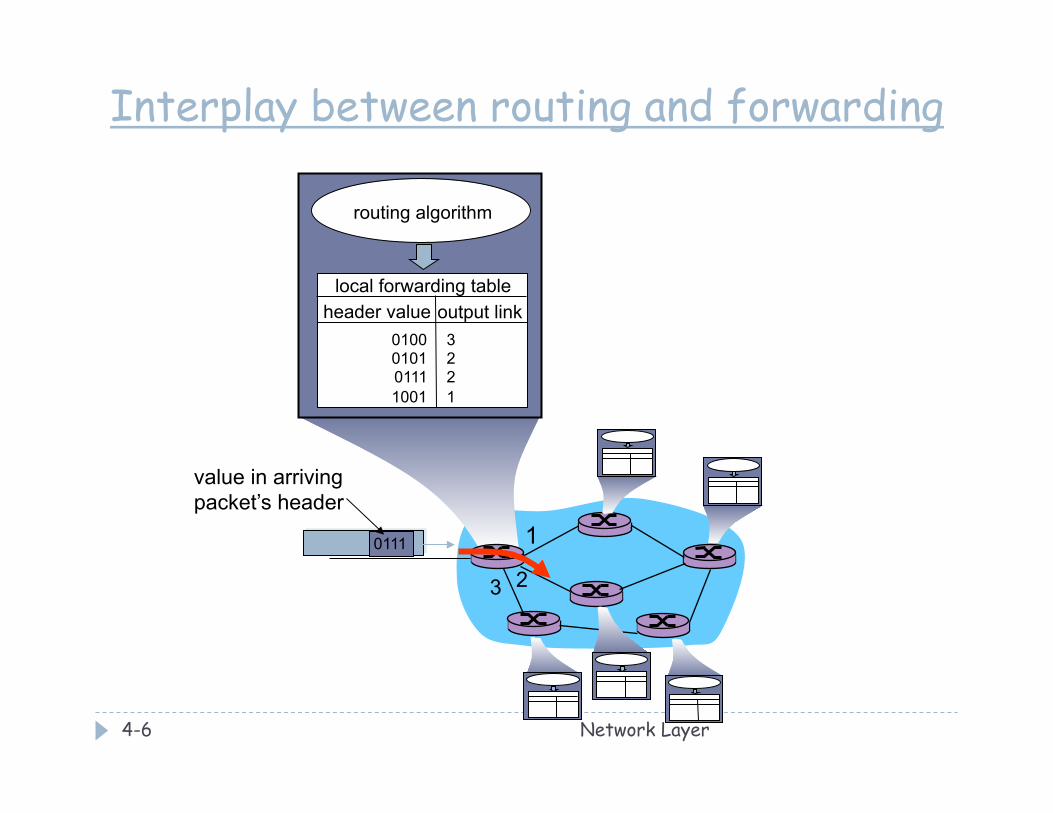
Network Layer 4-6
1
2 3
0111
value in arriving packet’s header
routing algorithm
local forwarding table header value output link
0100 0101 0111 1001
3 2 2 1
Interplay between routing and forwarding
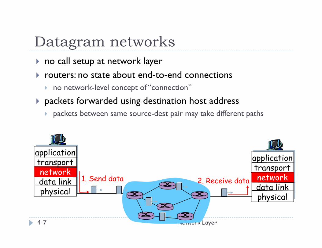
Datagram networks
Network Layer 4-7
} no call setup at network layer } routers: no state about end-to-end connections
} no network-level concept of “connection”
} packets forwarded using destination host address } packets between same source-dest pair may take different paths
application transport network data link physical
application transport network data link physical
1. Send data 2. Receive data
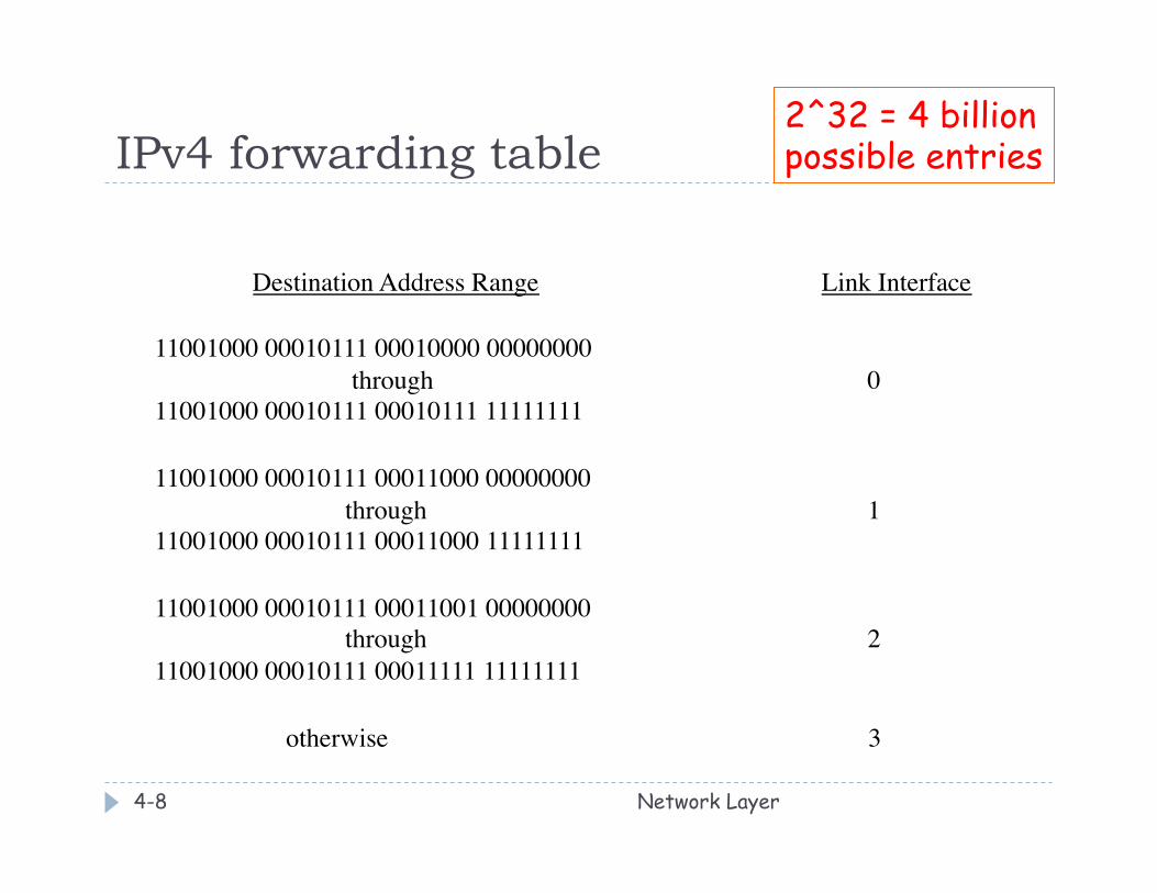
IPv4 forwarding table
Network Layer 4-8
Destination Address Range Link Interface 11001000 00010111 00010000 00000000 through 0 11001000 00010111 00010111 11111111 11001000 00010111 00011000 00000000 through 1 11001000 00010111 00011000 11111111 11001000 00010111 00011001 00000000 through 2 11001000 00010111 00011111 11111111 otherwise 3
2^32 = 4 billion possible entries
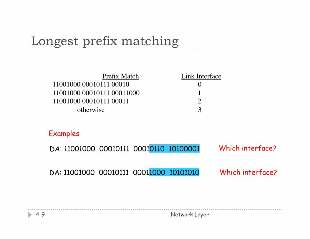
Longest prefix matching
Network Layer 4-9
Prefix Match Link Interface 11001000 00010111 00010 0 11001000 00010111 00011000 1 11001000 00010111 00011 2 otherwise 3
DA: 11001000 00010111 00011000 10101010
Examples
DA: 11001000 00010111 00010110 10100001 Which interface?
Which interface?
Chapter 4: Network Layer
Network Layer 4-10
} 4. 1 Introduction } 4.2 Virtual circuit and
datagram networks } 4.4 IP: Internet Protocol
} Datagram format } IPv4 addressing } ICMP } IPv6
} 4.5 Routing algorithms } Link state } Distance Vector } Hierarchical routing
} 4.6 Routing in the Internet } RIP } OSPF } BGP
} 4.7 Broadcast and multicast routing
The Internet Network layer
Network Layer 4-11
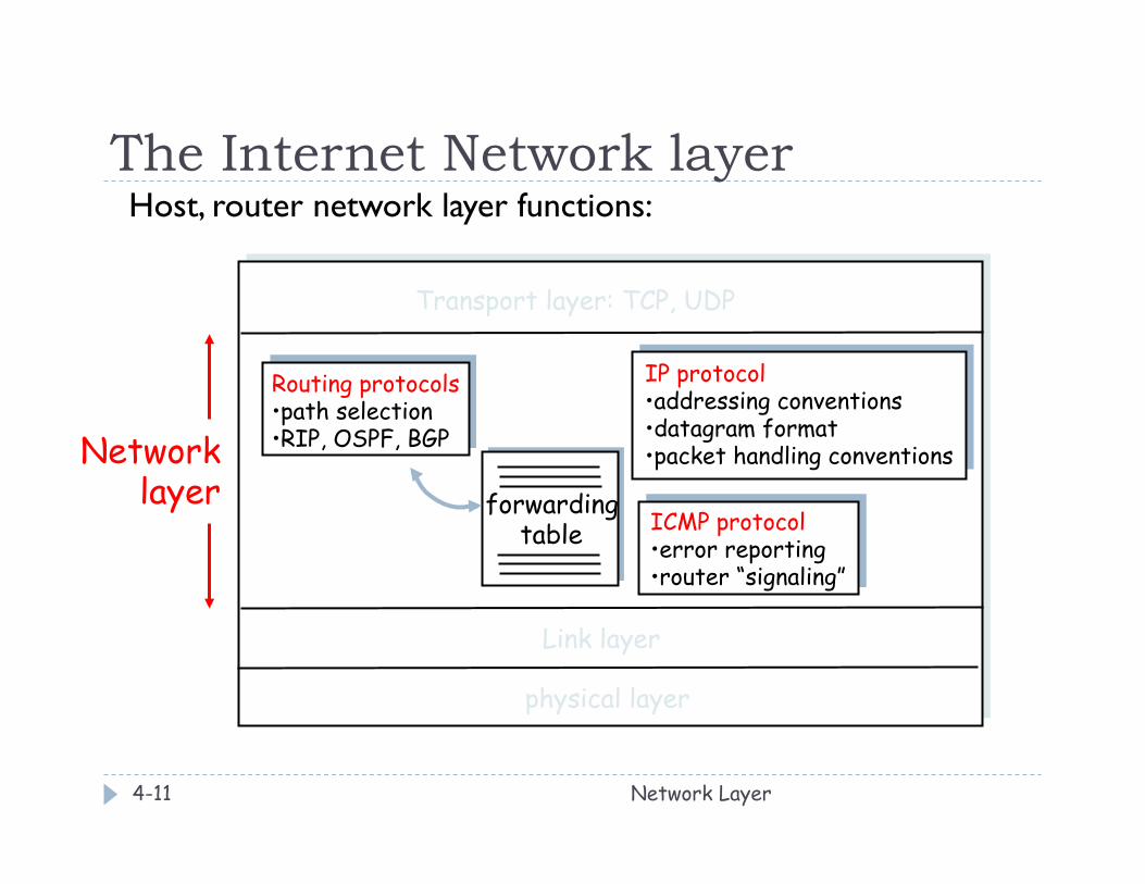
Host, router network layer functions:
forwarding table
Routing protocols • path selection • RIP, OSPF, BGP
IP protocol • addressing conventions • datagram format • packet handling conventions
ICMP protocol • error reporting • router “signaling”
Transport layer: TCP, UDP
Link layer
physical layer
Network layer
Chapter 4: Network Layer
Network Layer 4-12
} 4. 1 Introduction } 4.2 Virtual circuit and
datagram networks } 4.3 What’s inside a router } 4.4 IP: Internet Protocol
} Datagram format } IPv4 addressing } ICMP } IPv6
} 4.5 Routing algorithms } Link state } Distance Vector } Hierarchical routing
} 4.6 Routing in the Internet } RIP } OSPF } BGP
} 4.7 Broadcast and multicast routing
IPv4 datagram format
Network Layer 4-13
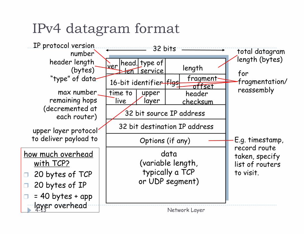
ver length
32 bits
data (variable length, typically a TCP
or UDP segment)
16-bit identifier header
checksum time to
live
32 bit source IP address
IP protocol version number
header length (bytes)
max number remaining hops
(decremented at each router)
for fragmentation/ reassembly
total datagram length (bytes)
upper layer protocol to deliver payload to
head. len
type of service
“type” of data flgs fragment offset
upper layer
32 bit destination IP address Options (if any) E.g. timestamp,
record route taken, specify list of routers to visit.
how much overhead with TCP?
❒ 20 bytes of TCP ❒ 20 bytes of IP ❒ = 40 bytes + app
layer overhead
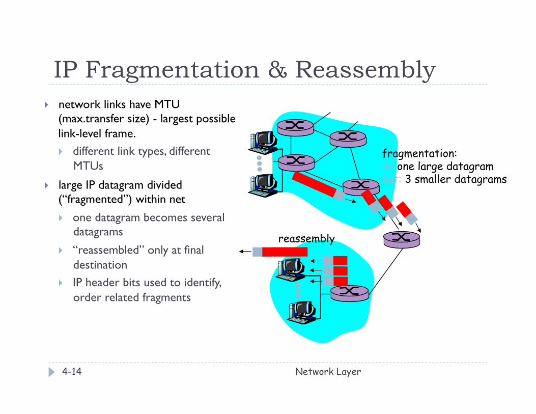
IP Fragmentation & Reassembly
Network Layer 4-14
} network links have MTU (max.transfer size) - largest possible link-level frame. } different link types, different
MTUs
} large IP datagram divided (“fragmented”) within net } one datagram becomes several
datagrams
} “reassembled” only at final destination
} IP header bits used to identify, order related fragments
fragmentation: in: one large datagram out: 3 smaller datagrams
reassembly
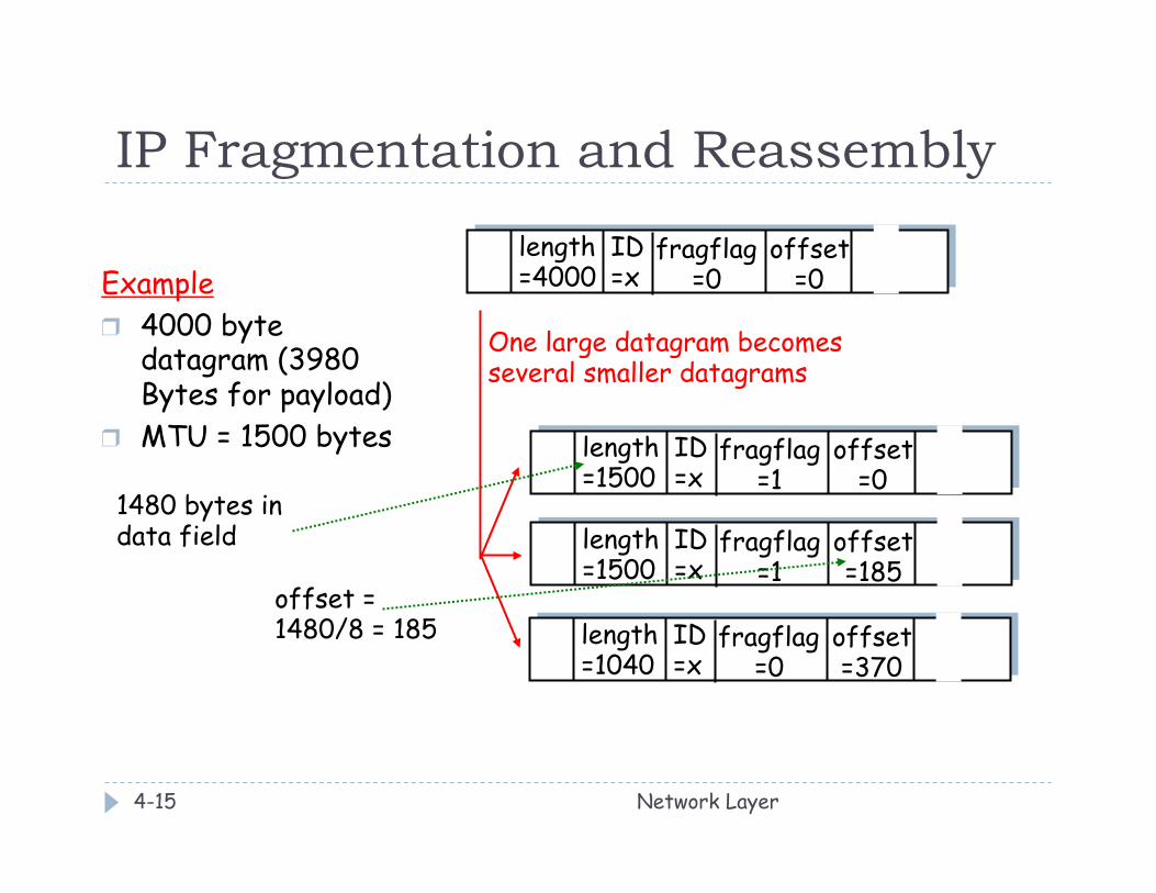
IP Fragmentation and Reassembly
Network Layer 4-15
ID =x
offset =0
fragflag =0
length =4000 Example
❒ 4000 byte datagram (3980 Bytes for payload)
❒ MTU = 1500 bytes ID =x
offset =0
fragflag =1
length =1500
ID =x
offset =185
fragflag =1
length =1500
ID =x
offset =370
fragflag =0
length =1040
One large datagram becomes several smaller datagrams
1480 bytes in data field
offset = 1480/8 = 185

IP Fragmentation - Another Example } Initial MTU = 3100 bytes (=3080 payload bytes) } As packet is routed, it encounters a link with MTU = 820
bytes (=800 payload bytes) } How will the fragments look like?
} ID = 4325, Flag = 1, offset = 0, length = 820 } ID = 4325, Flag = 1, offset = 100, length = 820 } ID = 4325, Flag = 1, offset = 200, length = 820 } ID = 4325, Flag = 0, offset = 300, length = 700
Network Layer 4-16
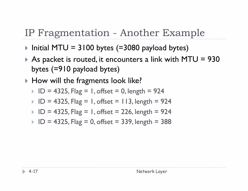
IP Fragmentation - Another Example } Initial MTU = 3100 bytes (=3080 payload bytes) } As packet is routed, it encounters a link with MTU = 930
bytes (=910 payload bytes) } How will the fragments look like?
} ID = 4325, Flag = 1, offset = 0, length = 924 } ID = 4325, Flag = 1, offset = 113, length = 924 } ID = 4325, Flag = 1, offset = 226, length = 924 } ID = 4325, Flag = 0, offset = 339, length = 388
Network Layer 4-17
Chapter 4: Network Layer
Network Layer 4-18
} 4. 1 Introduction } 4.2 Virtual circuit and
datagram networks } 4.3 What’s inside a router } 4.4 IP: Internet Protocol
} Datagram format } IPv4 addressing } ICMP } IPv6
} 4.5 Routing algorithms } Link state } Distance Vector } Hierarchical routing
} 4.6 Routing in the Internet } RIP } OSPF } BGP
} 4.7 Broadcast and multicast routing
IPv4 Addressing: introduction
Network Layer 4-19
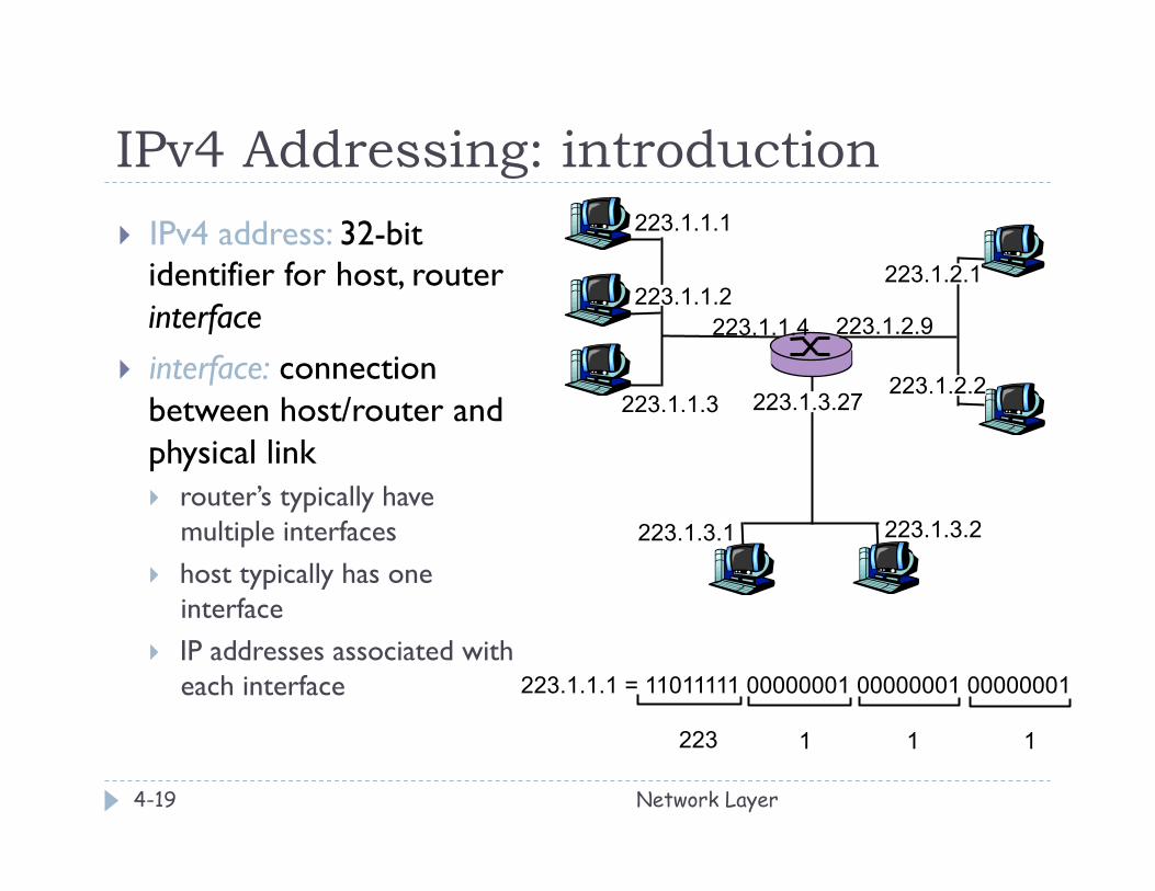
} IPv4 address: 32-bit identifier for host, router interface
} interface: connection between host/router and physical link } router’s typically have
multiple interfaces } host typically has one
interface } IP addresses associated with
each interface
223.1.1.1
223.1.1.2
223.1.1.3
223.1.1.4 223.1.2.9
223.1.2.2
223.1.2.1
223.1.3.2 223.1.3.1
223.1.3.27
223.1.1.1 = 11011111 00000001 00000001 00000001
223 1 1 1
Subnets
Network Layer 4-20
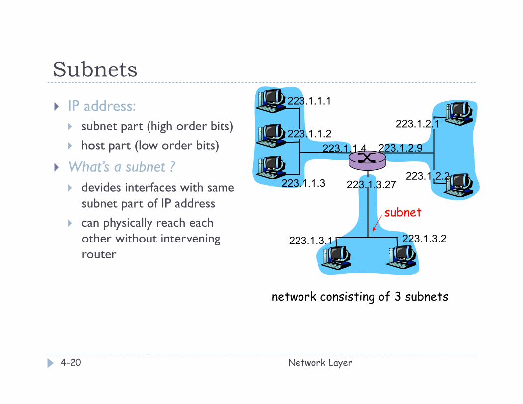
} IP address: } subnet part (high order bits) } host part (low order bits)
} What’s a subnet ? } devides interfaces with same
subnet part of IP address } can physically reach each
other without intervening router
223.1.1.1
223.1.1.2
223.1.1.3
223.1.1.4 223.1.2.9
223.1.2.2
223.1.2.1
223.1.3.2 223.1.3.1
223.1.3.27
network consisting of 3 subnets
subnet

Subnets
Network Layer 4-21
Recipe } To determine the subnets,
detach each interface from its host or router, creating islands of isolated networks. Each isolated network is called a subnet.
223.1.1.0/24 223.1.2.0/24
223.1.3.0/24
Subnet mask: /24
Subnets
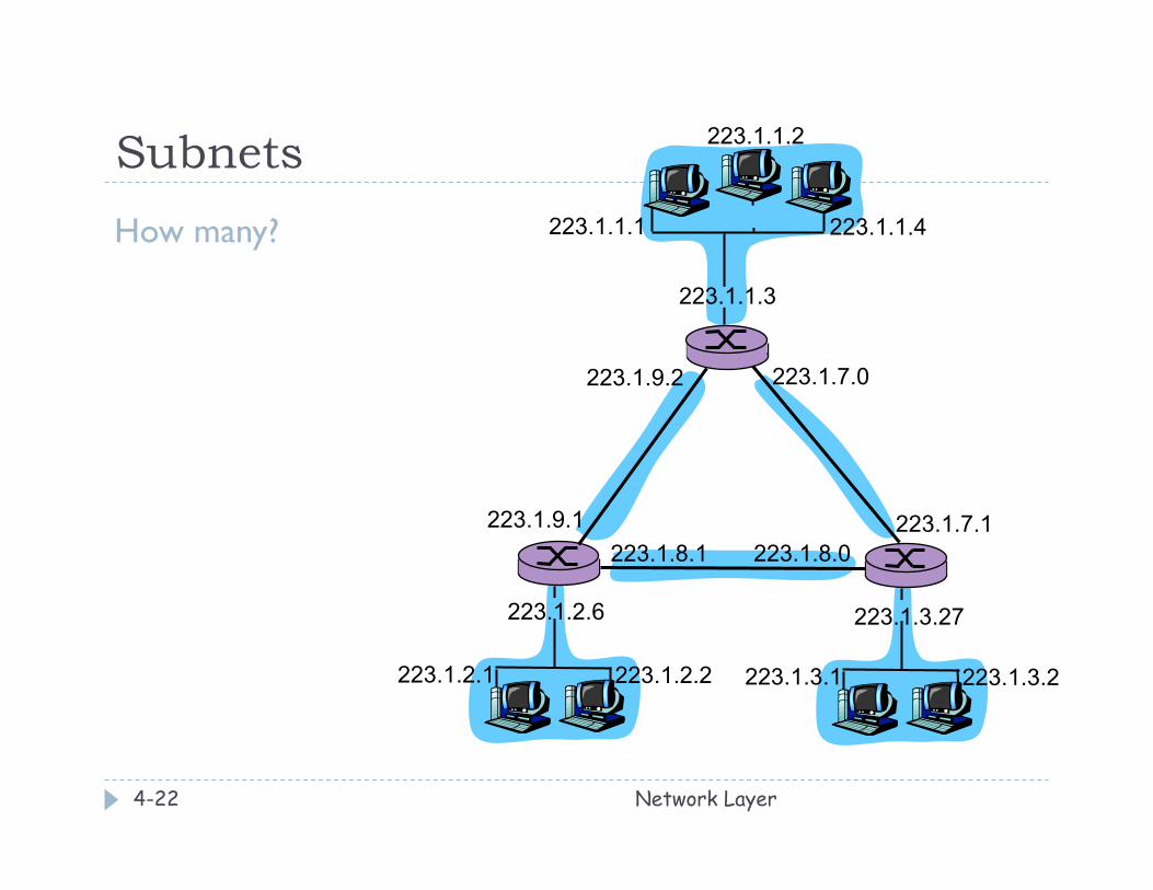
Network Layer 4-22
How many? 223.1.1.1
223.1.1.3
223.1.1.4
223.1.2.2 223.1.2.1
223.1.2.6
223.1.3.2 223.1.3.1
223.1.3.27
223.1.1.2
223.1.7.0
223.1.7.1 223.1.8.0 223.1.8.1
223.1.9.1
223.1.9.2
IP addressing: CIDR ***
Network Layer 4-23
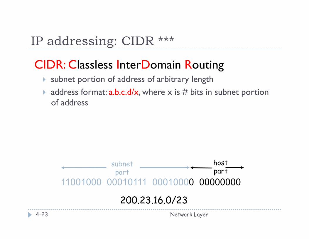
CIDR: Classless InterDomain Routing } subnet portion of address of arbitrary length } address format: a.b.c.d/x, where x is # bits in subnet portion
of address
11001000 00010111 00010000 00000000
subnet part
host part
200.23.16.0/23
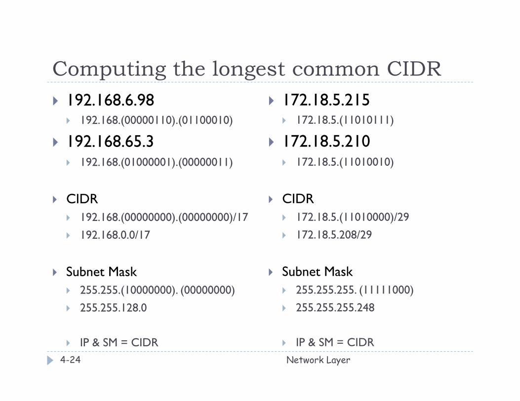
Computing the longest common CIDR } 192.168.6.98
} 192.168.(00000110).(01100010)
} 192.168.65.3 } 192.168.(01000001).(00000011)
} CIDR } 192.168.(00000000).(00000000)/17 } 192.168.0.0/17
} Subnet Mask } 255.255.(10000000). (00000000) } 255.255.128.0
} IP & SM = CIDR
} 172.18.5.215 } 172.18.5.(11010111)
} 172.18.5.210 } 172.18.5.(11010010)
} CIDR } 172.18.5.(11010000)/29 } 172.18.5.208/29
} Subnet Mask } 255.255.255. (11111000) } 255.255.255.248
} IP & SM = CIDR
Network Layer 4-24
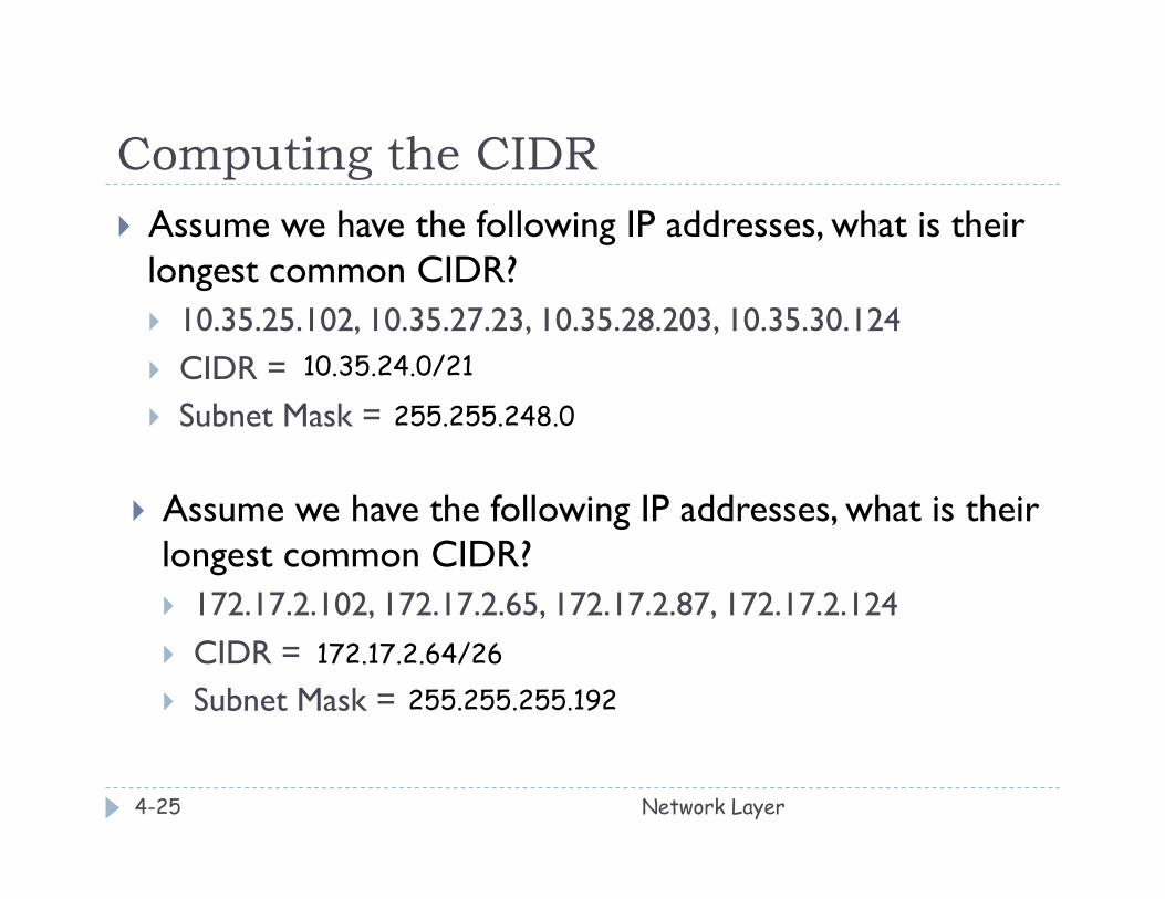
Computing the CIDR } Assume we have the following IP addresses, what is their
longest common CIDR? } 10.35.25.102, 10.35.27.23, 10.35.28.203, 10.35.30.124 } CIDR = } Subnet Mask =
Network Layer 4-25
10.35.24.0/21
} Assume we have the following IP addresses, what is their longest common CIDR? } 172.17.2.102, 172.17.2.65, 172.17.2.87, 172.17.2.124 } CIDR = } Subnet Mask =
172.17.2.64/26
255.255.248.0
255.255.255.192
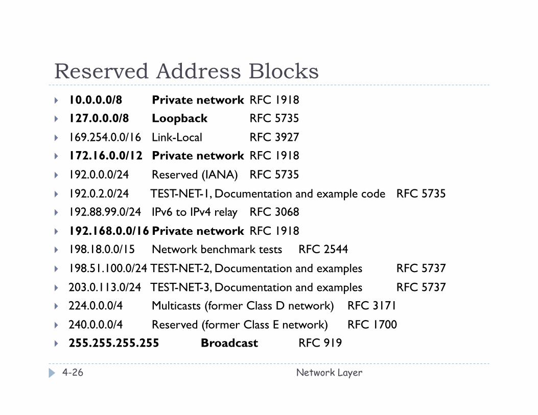
Reserved Address Blocks } 10.0.0.0/8 Private network RFC 1918 } 127.0.0.0/8 Loopback RFC 5735
} 169.254.0.0/16 Link-Local RFC 3927 } 172.16.0.0/12 Private network RFC 1918
} 192.0.0.0/24 Reserved (IANA) RFC 5735
} 192.0.2.0/24 TEST-NET-1, Documentation and example code RFC 5735 } 192.88.99.0/24 IPv6 to IPv4 relay RFC 3068
} 192.168.0.0/16 Private network RFC 1918 } 198.18.0.0/15 Network benchmark tests RFC 2544
} 198.51.100.0/24 TEST-NET-2, Documentation and examples RFC 5737
} 203.0.113.0/24 TEST-NET-3, Documentation and examples RFC 5737 } 224.0.0.0/4 Multicasts (former Class D network) RFC 3171
} 240.0.0.0/4 Reserved (former Class E network) RFC 1700 } 255.255.255.255 Broadcast RFC 919
Network Layer 4-26