Embed Size (px)
Citation preview
CSE 473/573 Computer Vision and Image Processing (CVIP)
Ifeoma [email protected]
Lecture 5 – Image formation (photometry)
Schedule
• Last class – Image formation and camera properties
• Today– Image formation – photometric properties
• Readings for today: Forsyth and Ponce 2.1, 2.2.4, Szeliski 2.2 (optional).
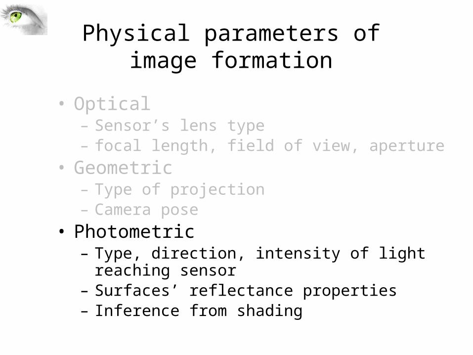
Physical parameters of image formation
• Optical– Sensor’s lens type– focal length, field of view, aperture
• Geometric– Type of projection– Camera pose
• Photometric– Type, direction, intensity of light reaching sensor– Surfaces’ reflectance properties– Inference from shading
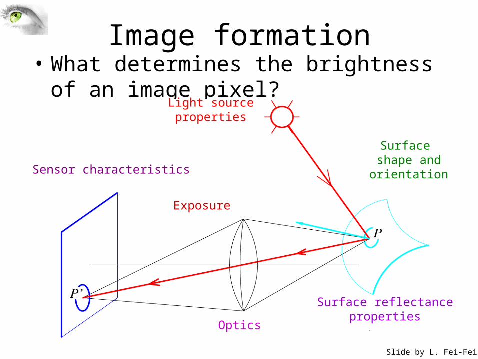
Image formation• What determines the brightness of an image
pixel?Light sourceproperties
Surface shape and orientation
Surface reflectanceproperties
Optics
Sensor characteristics
Slide by L. Fei-Fei
Exposure
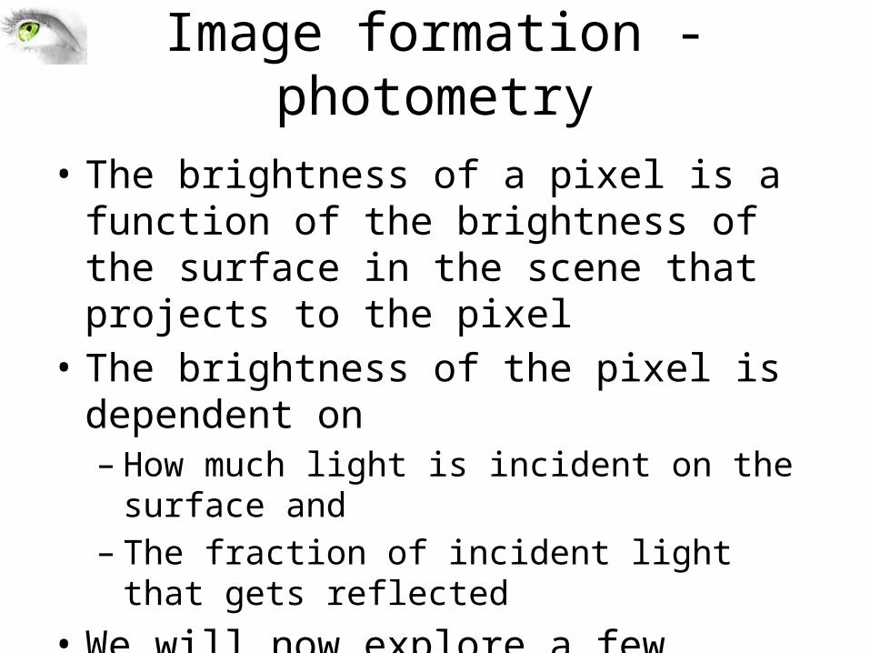
Image formation - photometry
• The brightness of a pixel is a function of the brightness of the surface in the scene that projects to the pixel
• The brightness of the pixel is dependent on – How much light is incident on the surface and – The fraction of incident light that gets reflected
• We will now explore a few simple models of shading
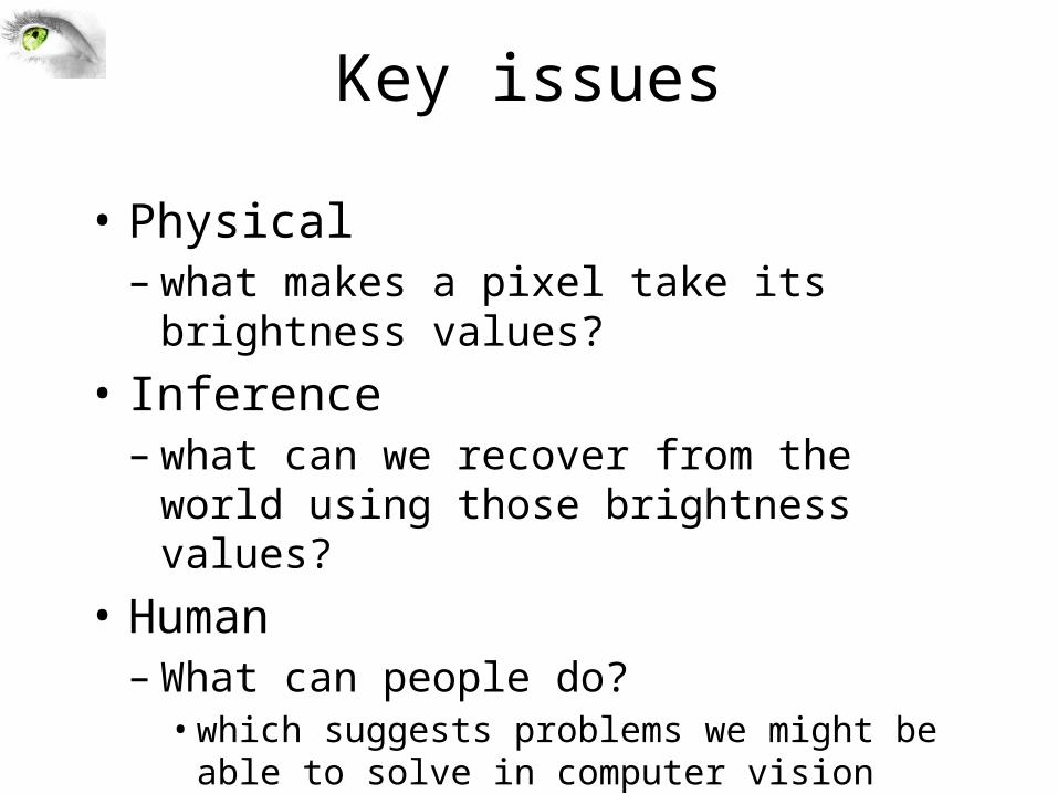
Key issues
• Physical– what makes a pixel take its brightness values?
• Inference– what can we recover from the world using those
brightness values?• Human– What can people do?• which suggests problems we might be able to solve in
computer vision
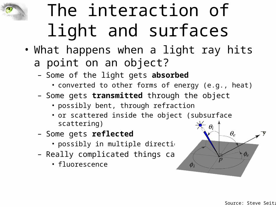
The interaction of light and surfaces
• What happens when a light ray hits a point on an object?– Some of the light gets absorbed
• converted to other forms of energy (e.g., heat)– Some gets transmitted through the object
• possibly bent, through refraction• or scattered inside the object (subsurface scattering)
– Some gets reflected• possibly in multiple directions at once
– Really complicated things can happen• fluorescence
Source: Steve Seitz
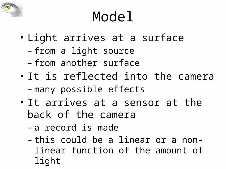
Model• Light arrives at a surface– from a light source– from another surface
• It is reflected into the camera– many possible effects
• It arrives at a sensor at the back of the camera– a record is made– this could be a linear or a non-linear function of the
amount of light
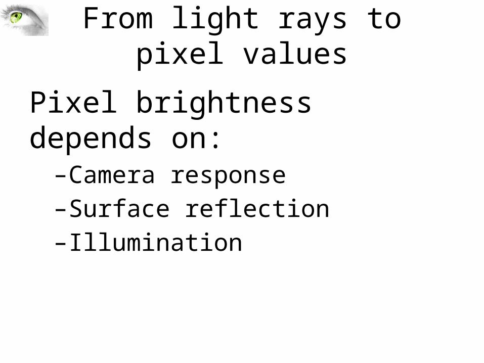
From light rays to pixel values
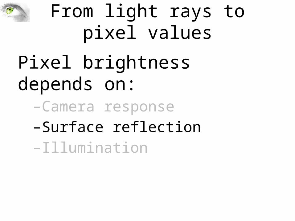
Pixel brightness depends on:–Camera response–Surface reflection–Illumination
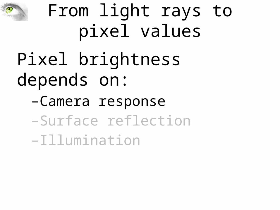
From light rays to pixel values
Pixel brightness depends on:–Camera response–Surface reflection–Illumination
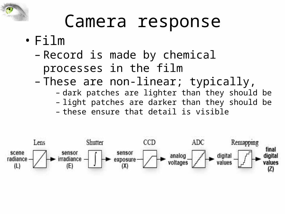
Camera response• Film– Record is made by chemical processes in the film– These are non-linear; typically,
– dark patches are lighter than they should be– light patches are darker than they should be– these ensure that detail is visible
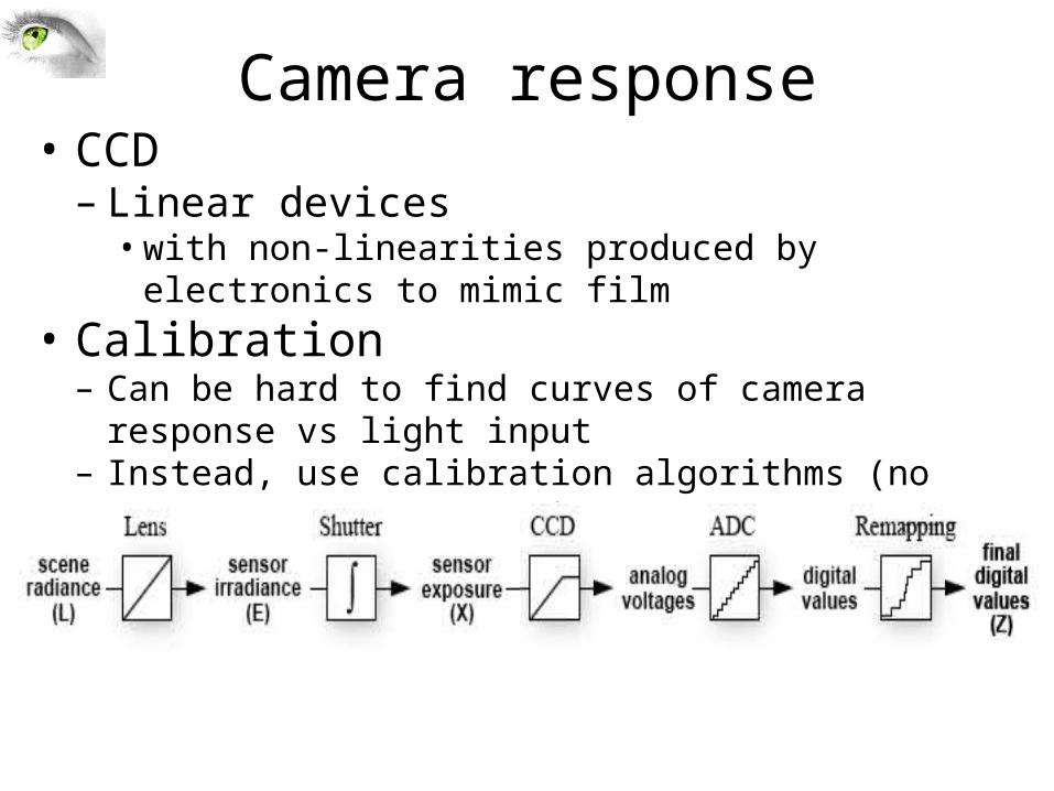
Camera response• CCD– Linear devices• with non-linearities produced by electronics to mimic film
• Calibration– Can be hard to find curves of camera response vs light input– Instead, use calibration algorithms (no covered in our course)
From light rays to pixel values
Pixel brightness depends on:–Camera response–Surface reflection–Illumination
Surface reflection
• Many effects can occur when light strikes a surface -- could be:– absorbed; transmitted; reflected; scattered• e.g. some people can see arteries, veins under their skin
– because light is transmitted through skin, reflected at blood vessel, transmitted out
– For simplicity, we assume that• surfaces don’t fluoresce• surfaces don’t emit light (i.e. are cool)• all the light leaving a point is due to that arriving at that
point
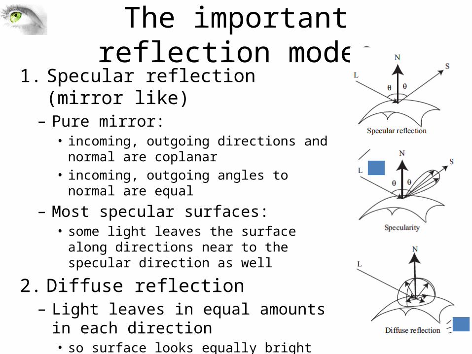
The important reflection modes1. Specular reflection (mirror like)– Pure mirror:• incoming, outgoing directions and normal are
coplanar • incoming, outgoing angles to normal are equal
– Most specular surfaces:• some light leaves the surface along directions near
to the specular direction as well
2. Diffuse reflection– Light leaves in equal amounts in each
direction• so surface looks equally bright from each viewing
direction

Reflection modes
• The 2 most important reflection modes are• Diffuse reflection – incident light is spread evenly over the whole
hemisphere of out going directions• Specular reflection – reflected light is concentrated in a single
direction• Specular direction S is coplanar with the normal N and source direction L• Incident angle = reflection angle = q
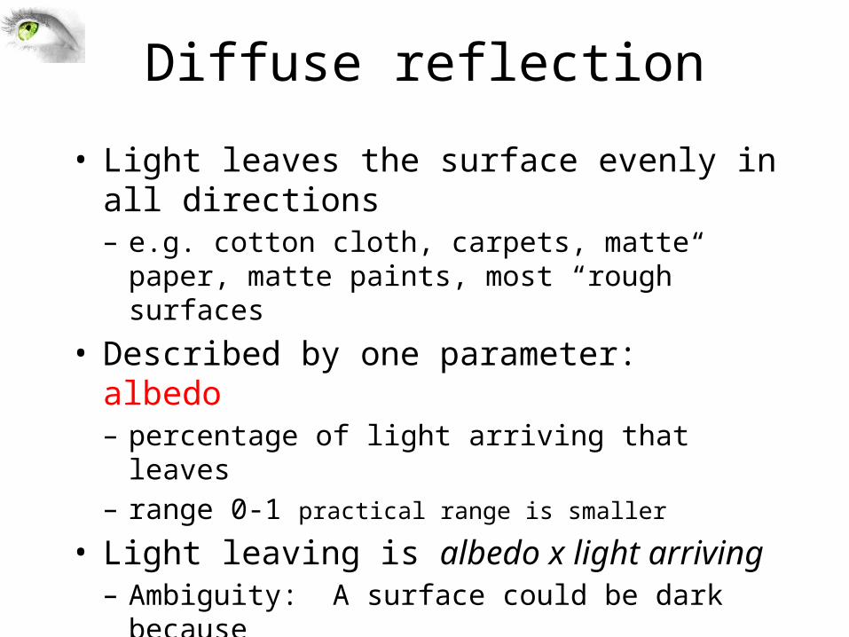
Diffuse reflection
• Light leaves the surface evenly in all directions– e.g. cotton cloth, carpets, matte paper, matte paints, most
“rough” surfaces
• Described by one parameter: albedo– percentage of light arriving that leaves– range 0-1 practical range is smaller
• Light leaving is albedo x light arriving– Ambiguity: A surface could be dark because• It reflects a small percentage of the light arriving• There isn’t very much light arriving
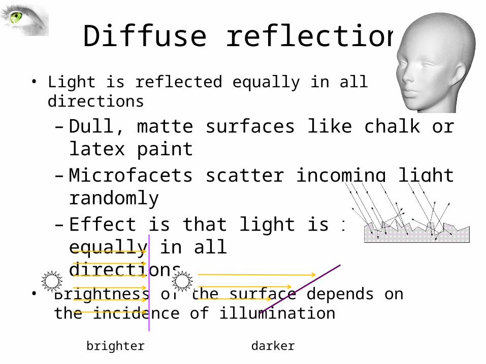
Diffuse reflection• Light is reflected equally in all directions
– Dull, matte surfaces like chalk or latex paint– Microfacets scatter incoming light randomly– Effect is that light is reflected equally in all
directions• Brightness of the surface depends on
the incidence of illumination
brighter darker
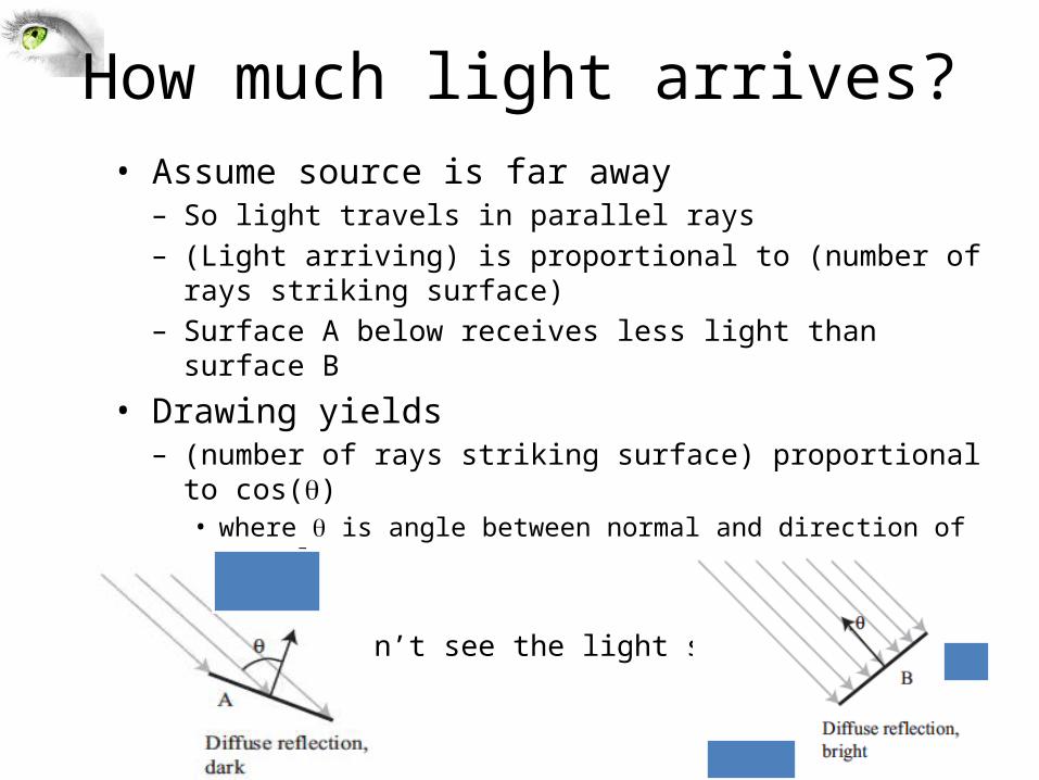
How much light arrives?• Assume source is far away– So light travels in parallel rays– (Light arriving) is proportional to (number of rays striking surface)– Surface A below receives less light than surface B
• Drawing yields– (number of rays striking surface) proportional to cos(q)
• where q is angle between normal and direction of travel
• Shadows– If point can’t see the light source, it is in shadow
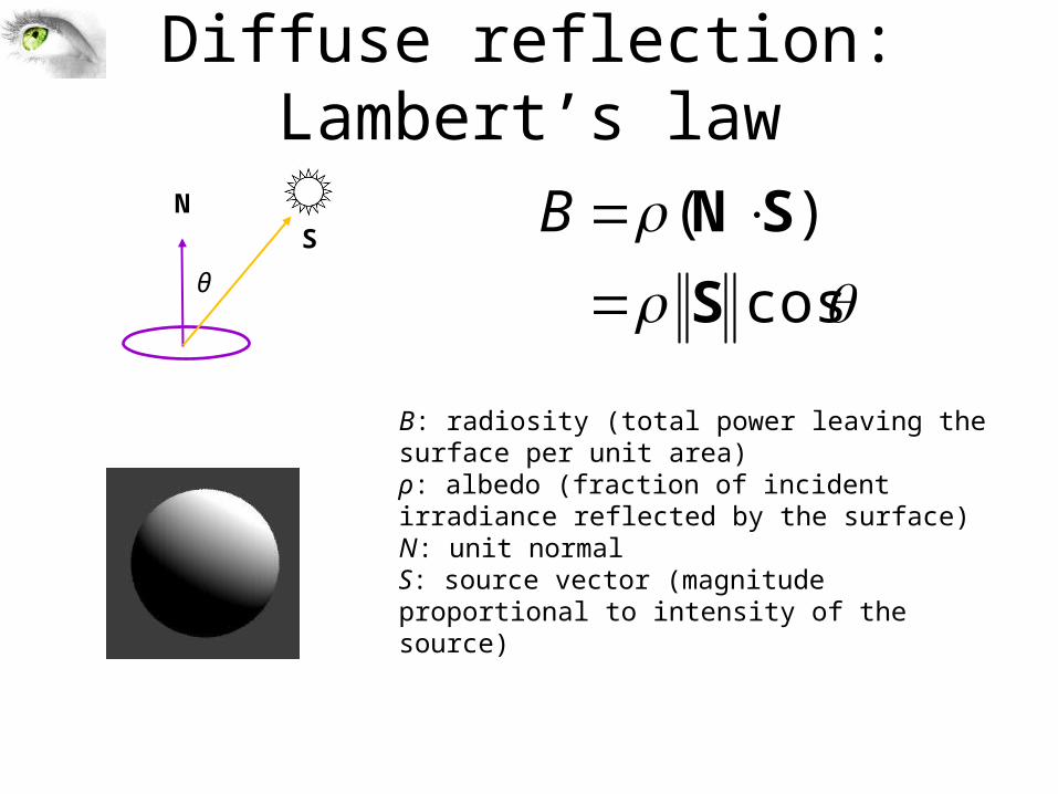
Diffuse reflection: Lambert’s law
cos
)(
S
SN
BNS
B: radiosity (total power leaving the surface per unit area)ρ: albedo (fraction of incident irradiance reflected by the surface)N: unit normalS: source vector (magnitude proportional to intensity of the source)
θ
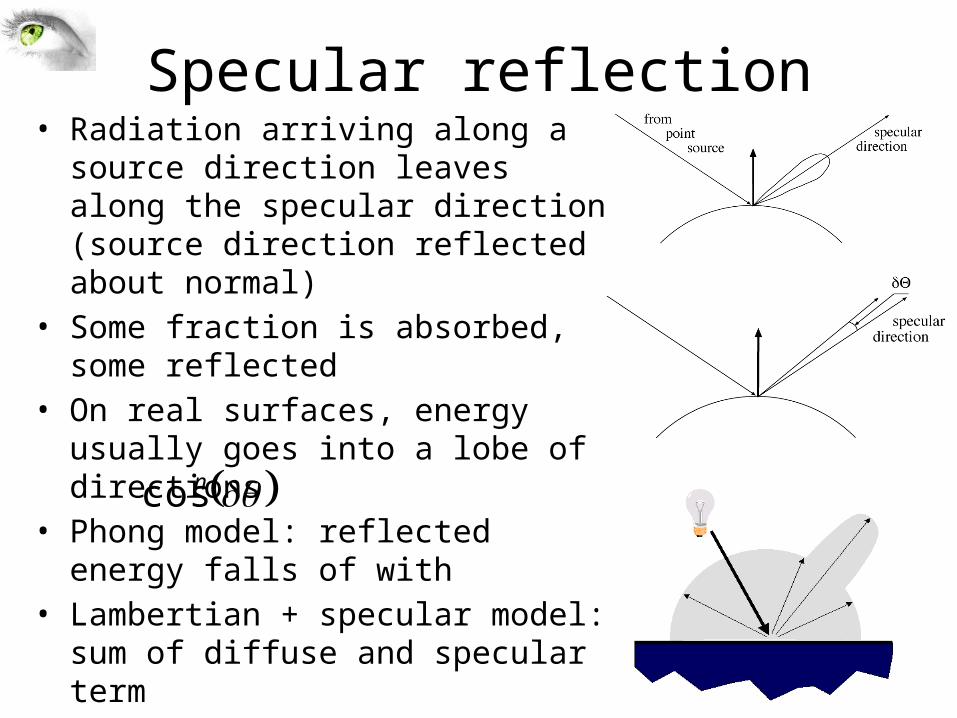
Specular reflection• Radiation arriving along a source
direction leaves along the specular direction (source direction reflected about normal)
• Some fraction is absorbed, some reflected
• On real surfaces, energy usually goes into a lobe of directions
• Phong model: reflected energy falls of with
• Lambertian + specular model: sum of diffuse and specular term
ncos
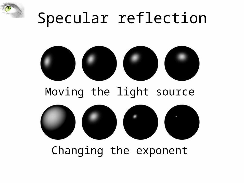
Specular reflection
Moving the light source
Changing the exponent
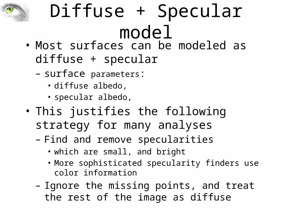
Diffuse + Specular model• Most surfaces can be modeled as diffuse + specular– surface parameters: • diffuse albedo, • specular albedo,
• This justifies the following strategy for many analyses– Find and remove specularities• which are small, and bright• More sophisticated specularity finders use color information
– Ignore the missing points, and treat the rest of the image as diffuse
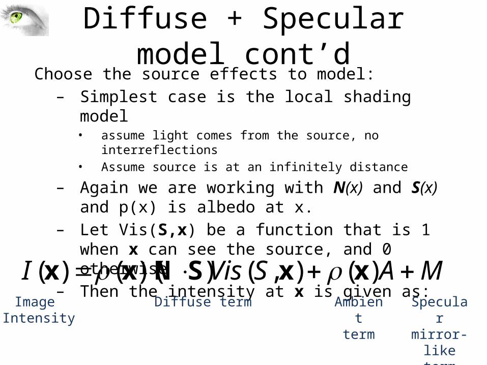
Diffuse + Specular model cont’dChoose the source effects to model:– Simplest case is the local shading model
• assume light comes from the source, no interreflections• Assume source is at an infinitely distance
– Again we are working with N(x) and S(x) and p(x) is albedo at x.
– Let Vis(S,x) be a function that is 1 when x can see the source, and 0 otherwise
– Then the intensity at x is given as:
MASVisI )(),())(()( xxSNxx Image
IntensityDiffuse term Ambient
termSpecular
mirror-liketerm
From light rays to pixel values
Pixel brightness depends on:–Camera response–Surface reflection–Illumination
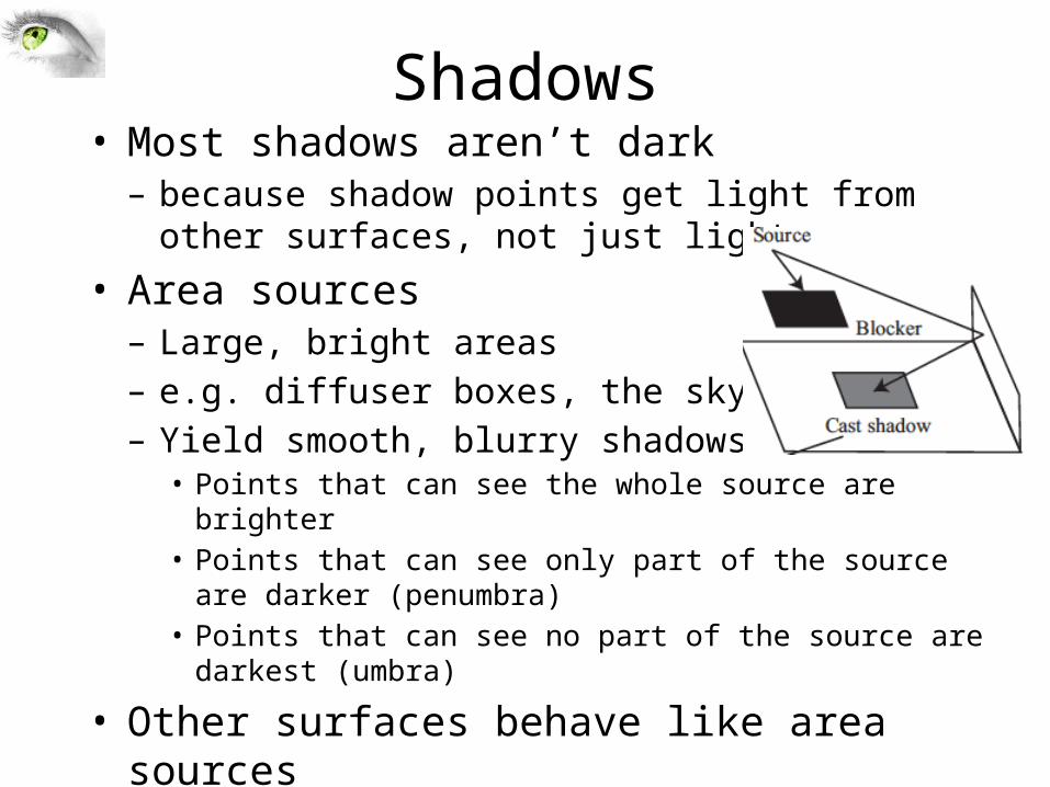
Shadows• Most shadows aren’t dark– because shadow points get light from other surfaces, not
just light source
• Area sources– Large, bright areas– e.g. diffuser boxes, the sky– Yield smooth, blurry shadows• Points that can see the whole source are brighter• Points that can see only part of the source are darker (penumbra)• Points that can see no part of the source are darkest (umbra)
• Other surfaces behave like area sources– Smooth, blurry shadows are common (and sometimes too
faint to see)
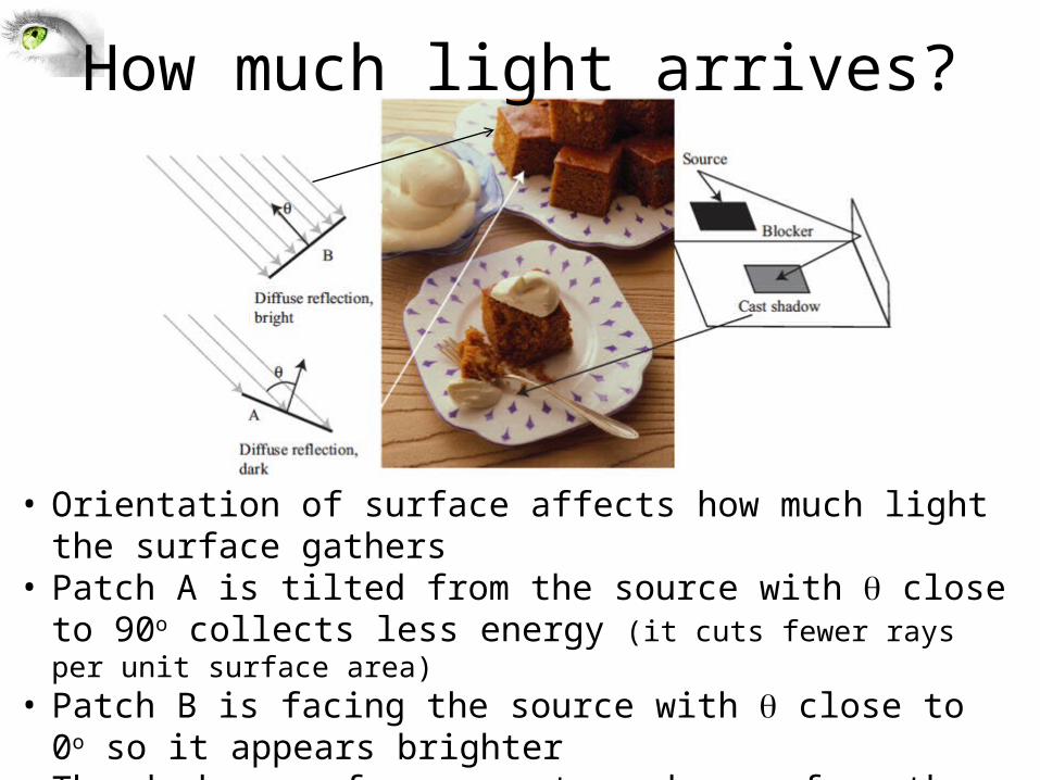
How much light arrives?
• Orientation of surface affects how much light the surface gathers• Patch A is tilted from the source with q close to 90o collects less
energy (it cuts fewer rays per unit surface area)• Patch B is facing the source with q close to 0o so it appears brighter• The darker surfaces are turned away from the illumination direction
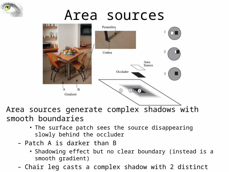
Area sources
Area sources generate complex shadows with smooth boundaries• The surface patch sees the source disappearing slowly behind the occluder
– Patch A is darker than B • Shadowing effect but no clear boundary (instead is a smooth gradient)
– Chair leg casts a complex shadow with 2 distinct regions• Umbra – no source is seen at all• Penumbra – source is partially seen
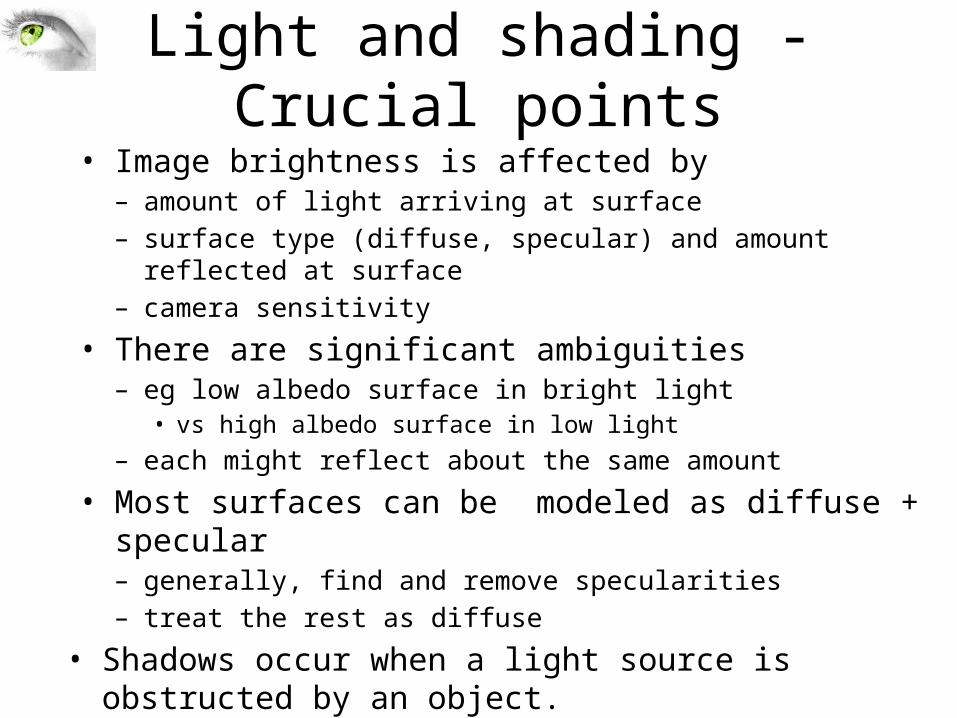
Light and shading - Crucial points• Image brightness is affected by– amount of light arriving at surface– surface type (diffuse, specular) and amount reflected at surface– camera sensitivity
• There are significant ambiguities– eg low albedo surface in bright light
• vs high albedo surface in low light– each might reflect about the same amount
• Most surfaces can be modeled as diffuse + specular– generally, find and remove specularities– treat the rest as diffuse
• Shadows occur when a light source is obstructed by an object. – occupies all of the space behind the opaque object with light in front of it.
Inference from shading
• Radiometric calibration and high dynamic range images• The shape of specularities• Inferring lightness and illumination• Photometric stereo: shape from multiple shaded images
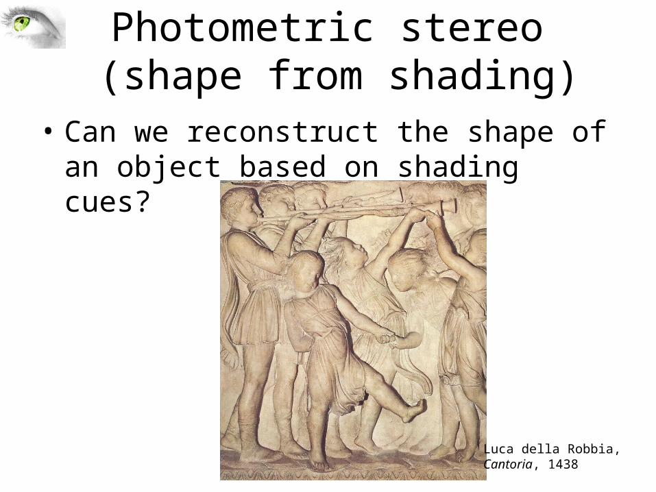
Photometric stereo (shape from shading)
• Can we reconstruct the shape of an object based on shading cues?
Luca della Robbia,Cantoria, 1438
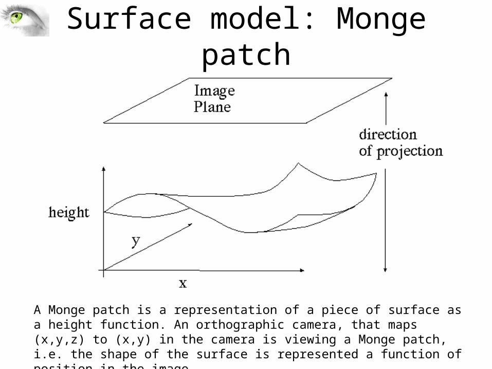
Surface model: Monge patch
A Monge patch is a representation of a piece of surface as a height function. An orthographic camera, that maps (x,y,z) to (x,y) in the camera is viewing a Monge patch, i.e. the shape of the surface is represented a function of position in the image
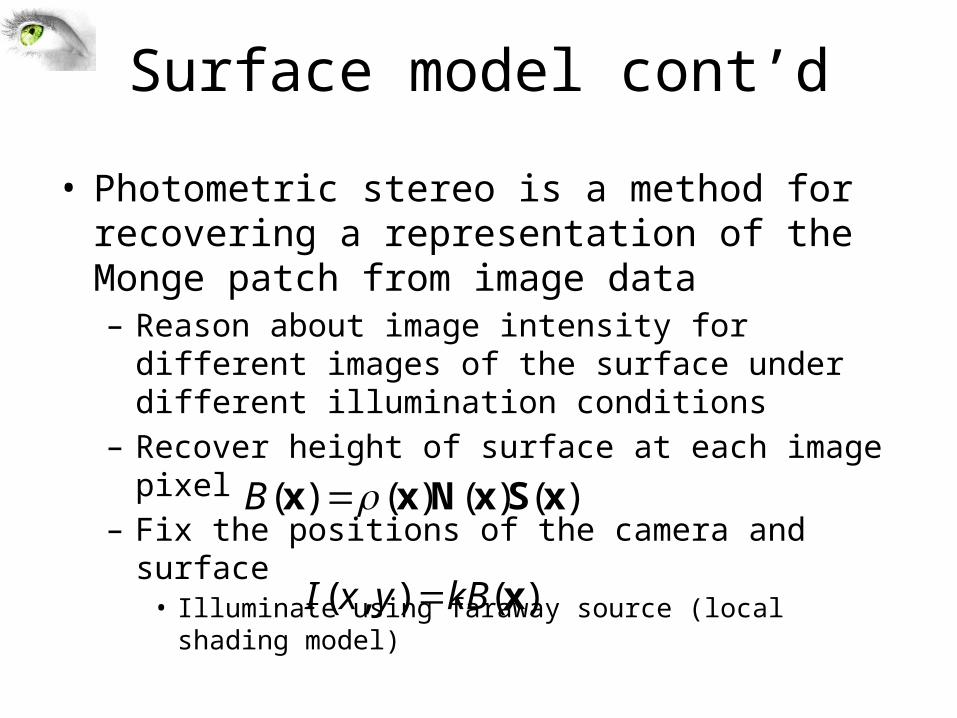
Surface model cont’d
• Photometric stereo is a method for recovering a representation of the Monge patch from image data– Reason about image intensity for different images of the
surface under different illumination conditions– Recover height of surface at each image pixel– Fix the positions of the camera and surface
• Illuminate using faraway source (local shading model)
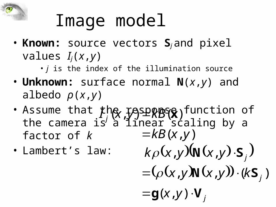
– The intensity value of a pixel at (x,y) is now)()()()( xSxNxx B
)(),( xkByxI
j
j
j
j
yx
kyxyx
yxyxk
yxkB
kByxI
Vg
SN
SN
x
),(
)(,,
,,
),(
)(),(
Image model• Known: source vectors Sj and pixel values Ij(x,y)
• j is the index of the illumination source
• Unknown: surface normal N(x,y) and albedo ρ(x,y) • Assume that the response function of the camera is a
linear scaling by a factor of k • Lambert’s law:
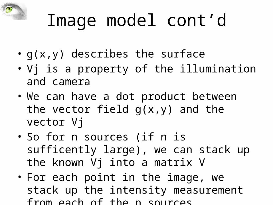
Image model cont’d
• g(x,y) describes the surface• Vj is a property of the illumination and camera• We can have a dot product between the vector field
g(x,y) and the vector Vj• So for n sources (if n is sufficently large), we can stack
up the known Vj into a matrix V• For each point in the image, we stack up the intensity
measurement from each of the n sources

Least squares problem
• Obtain least-squares solution for g(x,y) (which we defined as N(x,y) (x,y))
• Since N(x,y) is the unit normal, (x,y) is given by the magnitude of g(x,y)
• Finally, N(x,y) = g(x,y) / (x,y)
),(
),(
),(
),(
2
1
2
1
yx
yxI
yxI
yxI
Tn
T
T
n
g
V
V
V
(n × 1)known known unknown
(n × 3) (3 × 1)
• For each pixel, set up a linear system:
F&P 2nd ed., sec. 2.2.4
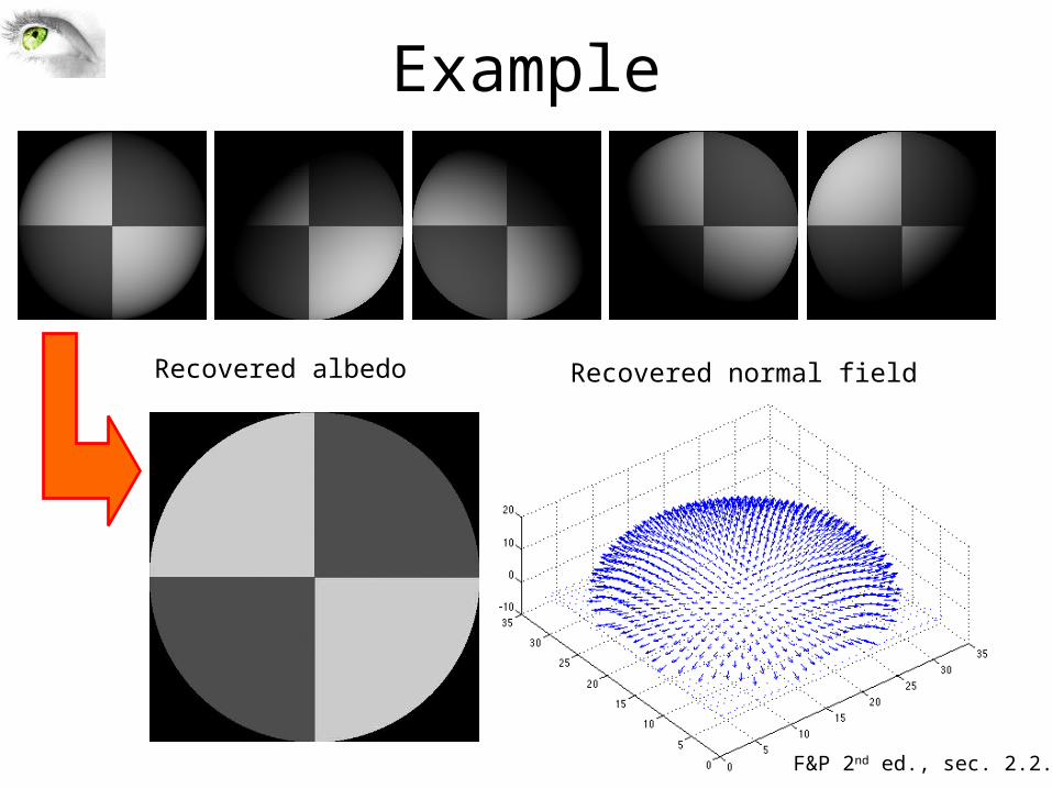
Example
Recovered albedo Recovered normal field
F&P 2nd ed., sec. 2.2.4
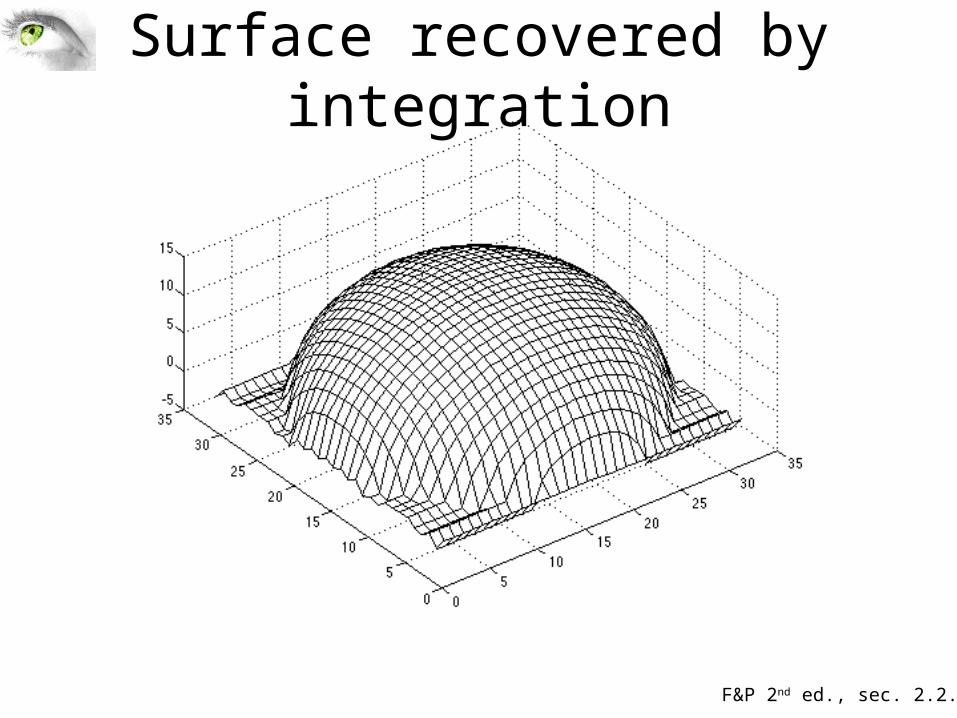
Surface recovered by integration
F&P 2nd ed., sec. 2.2.4
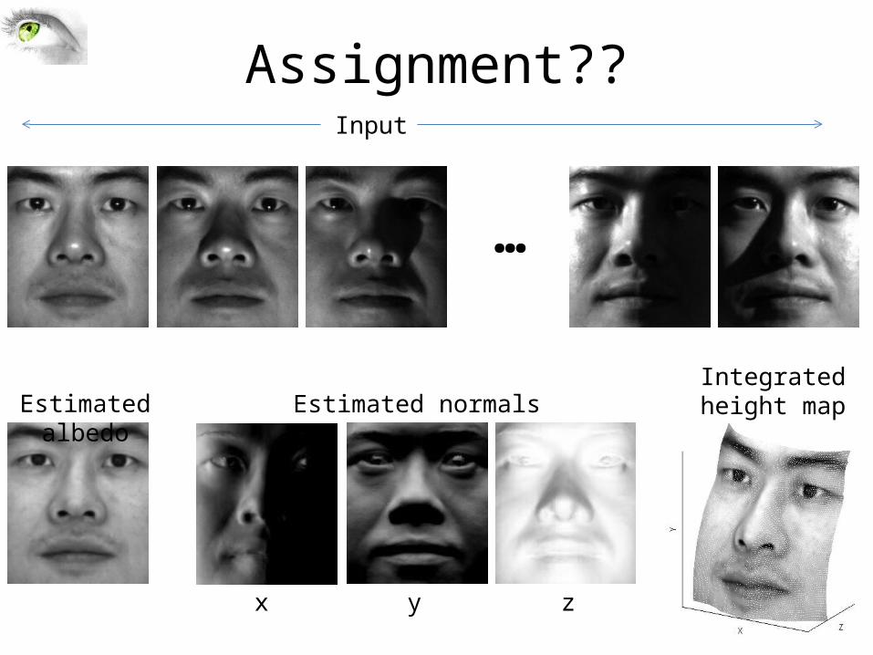
Assignment??
…
Input
Estimated albedo Estimated normalsIntegrated height map
x y z
Limitations
• Orthographic camera model• Simplistic reflectance and lighting model• No shadows• No inter-reflections• No missing data• Integration is tricky
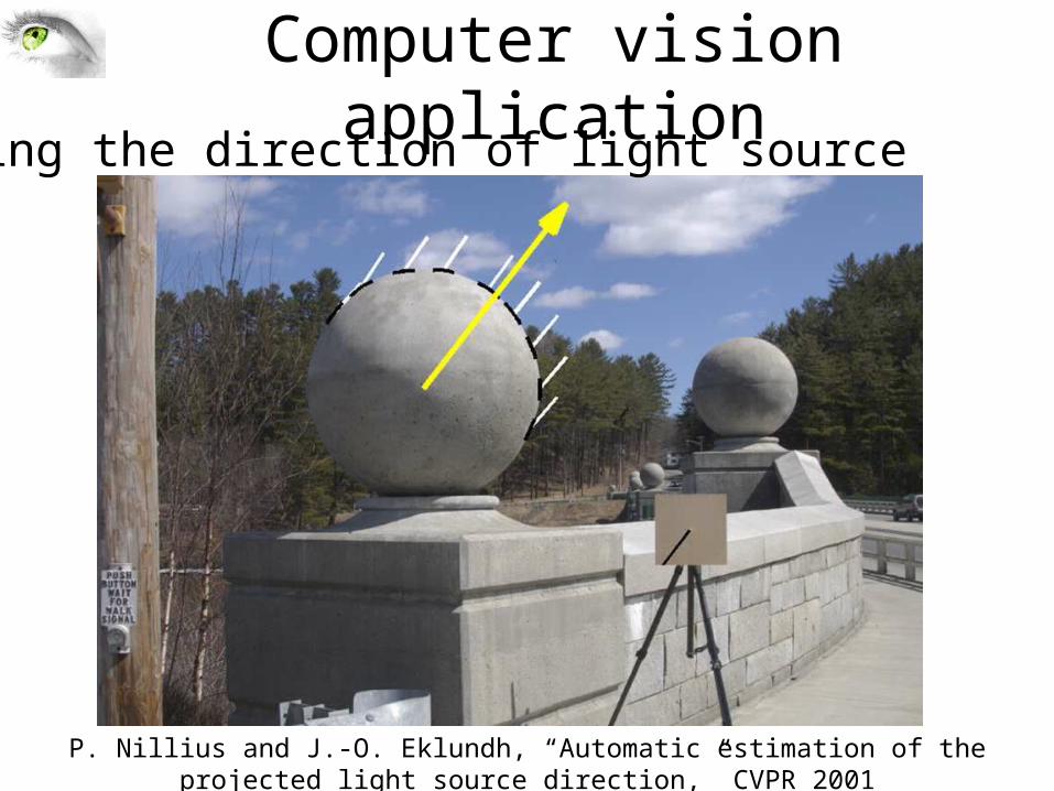
Computer vision application
P. Nillius and J.-O. Eklundh, “Automatic estimation of the projected light source direction,” CVPR 2001
Finding the direction of light source
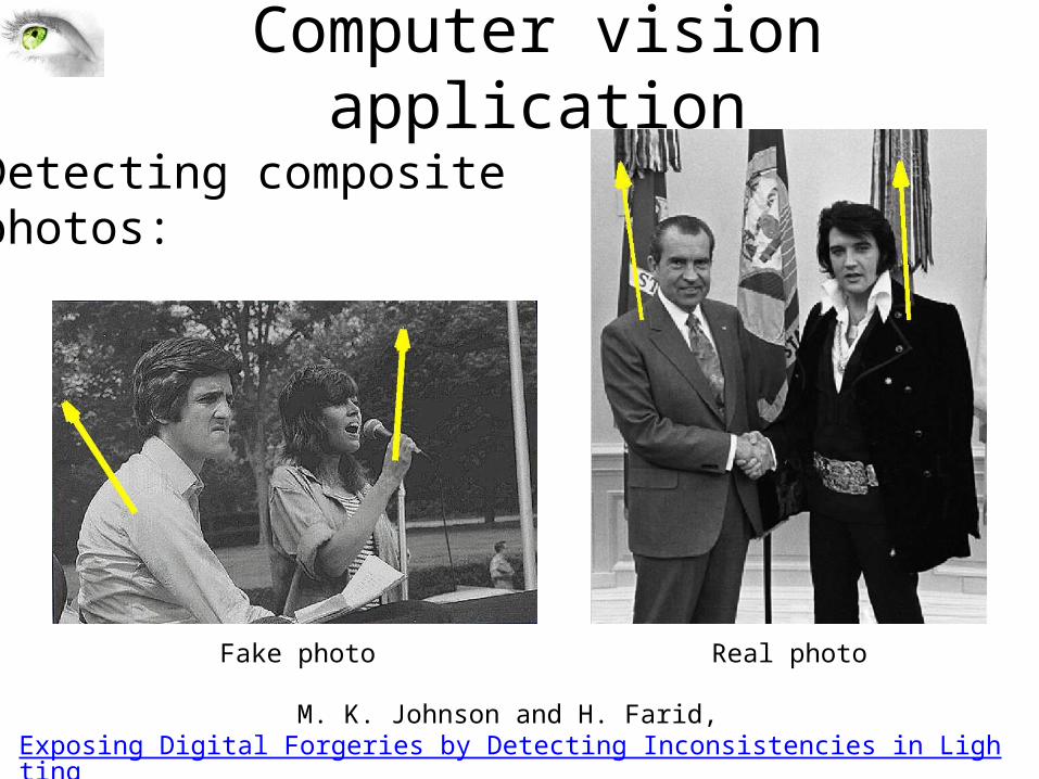
Computer vision application
Fake photo Real photo
M. K. Johnson and H. Farid, Exposing Digital Forgeries by Detecting Inconsistencies in Lighting, ACM Multimedia and Security Workshop, 2005.
Detecting composite photos:
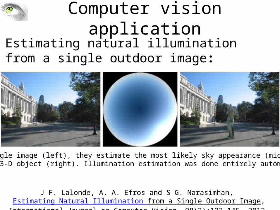
J-F. Lalonde, A. A. Efros and S G. Narasimhan, Estimating Natural Illumination from a Single Outdoor Image, International Journal on Computer Vision, 98(2):123-145, 2012.
Estimating natural illumination from a single outdoor image:
From a single image (left), they estimate the most likely sky appearance (middle) and insert a 3-D object (right). Illumination estimation was done entirely automatically
Computer vision application

Slide Credits
• David A. Forsyth - UIUC• Svetlana Lazebnik – UIUC

Next class
• Color• Readings for next lecture: – Forsyth and Ponce Chp 3; Szeliski 2.3.2 (optional)
• Readings for today: – Forsyth and Ponce 2.1, 2.2.4; Szeliski 2.2 (optional)

Questions