Embed Size (px)
Citation preview
CSE401N:Computer Networks
Lecture 11+12+13The Internet Protocol(IP)
IPv4 & IPv6CIDR, Subnet & NAT
DHCP,ARP
04/18/234a-2
The Internet Network layer
routingtable
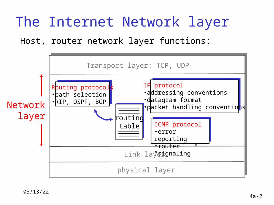
Host, router network layer functions:
Routing protocols•path selection•RIP, OSPF, BGP
IP protocol•addressing conventions•datagram format•packet handling conventions
ICMP protocol•error reporting•router “signaling”
Transport layer: TCP, UDP
Link layer
physical layer
Networklayer
04/18/234a-3
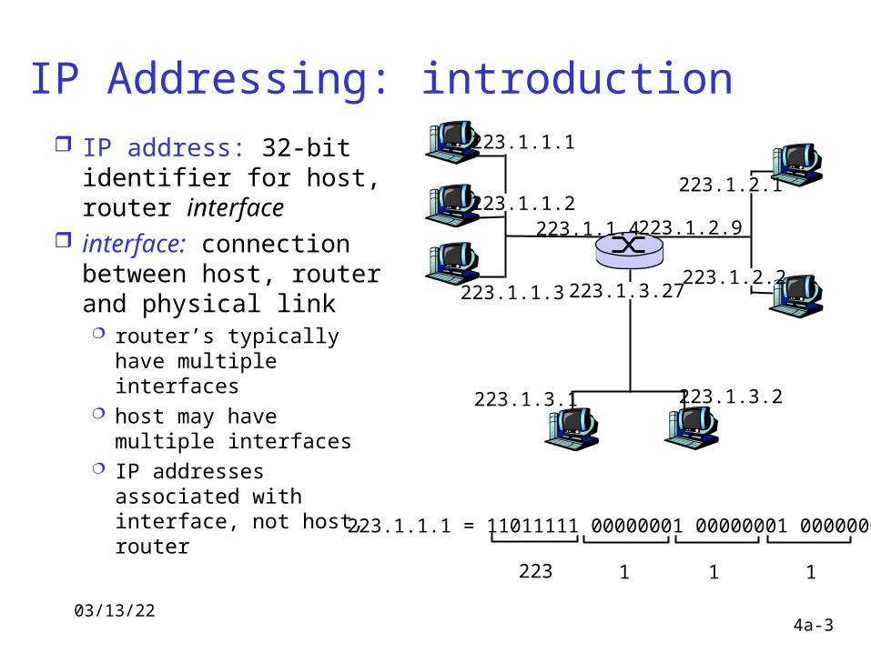
IP Addressing: introduction IP address: 32-bit
identifier for host, router interface
interface: connection between host, router and physical link router’s typically have
multiple interfaces host may have
multiple interfaces IP addresses
associated with interface, not host, router
223.1.1.1
223.1.1.2
223.1.1.3
223.1.1.4 223.1.2.9
223.1.2.2
223.1.2.1
223.1.3.2223.1.3.1
223.1.3.27
223.1.1.1 = 11011111 00000001 00000001 00000001
223 1 11
04/18/234a-4
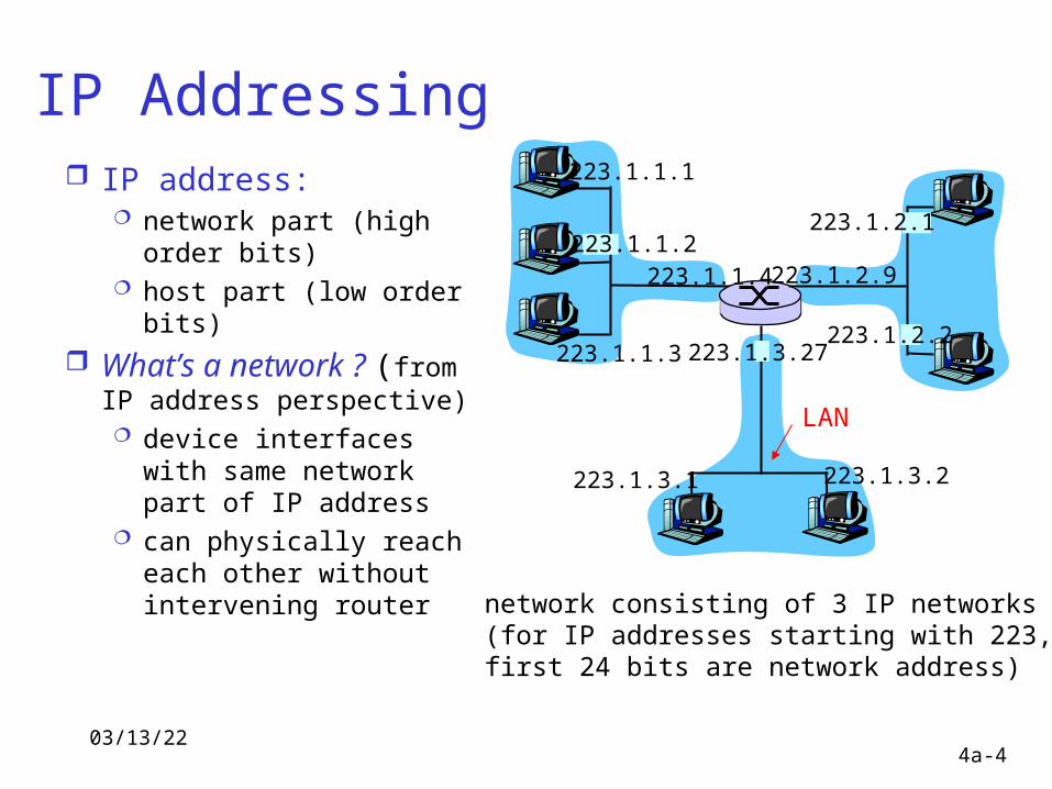
IP Addressing IP address:
network part (high order bits)
host part (low order bits)
What’s a network ? (from IP address perspective) device interfaces with
same network part of IP address
can physically reach each other without intervening router
223.1.1.1
223.1.1.2
223.1.1.3
223.1.1.4 223.1.2.9
223.1.2.2
223.1.2.1
223.1.3.2223.1.3.1
223.1.3.27
network consisting of 3 IP networks(for IP addresses starting with 223, first 24 bits are network address)
LAN
04/18/234a-5
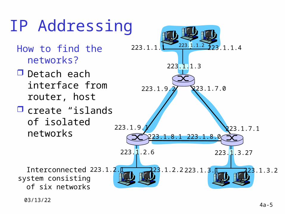
IP AddressingHow to find the
networks? Detach each
interface from router, host
create “islands of isolated networks
223.1.1.1
223.1.1.3
223.1.1.4
223.1.2.2223.1.2.1
223.1.2.6
223.1.3.2223.1.3.1
223.1.3.27
223.1.1.2
223.1.7.0
223.1.7.1223.1.8.0223.1.8.1
223.1.9.1
223.1.9.2
Interconnected system consisting
of six networks
04/18/234a-6
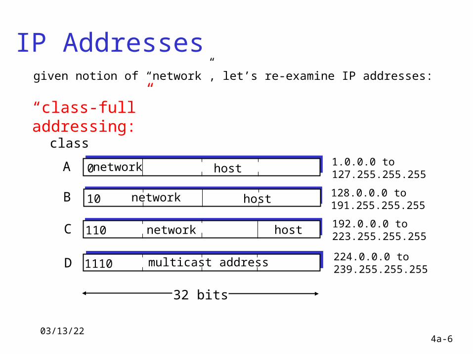
IP Addresses
0network host
10 network host
110 network host
1110 multicast address
A
B
C
D
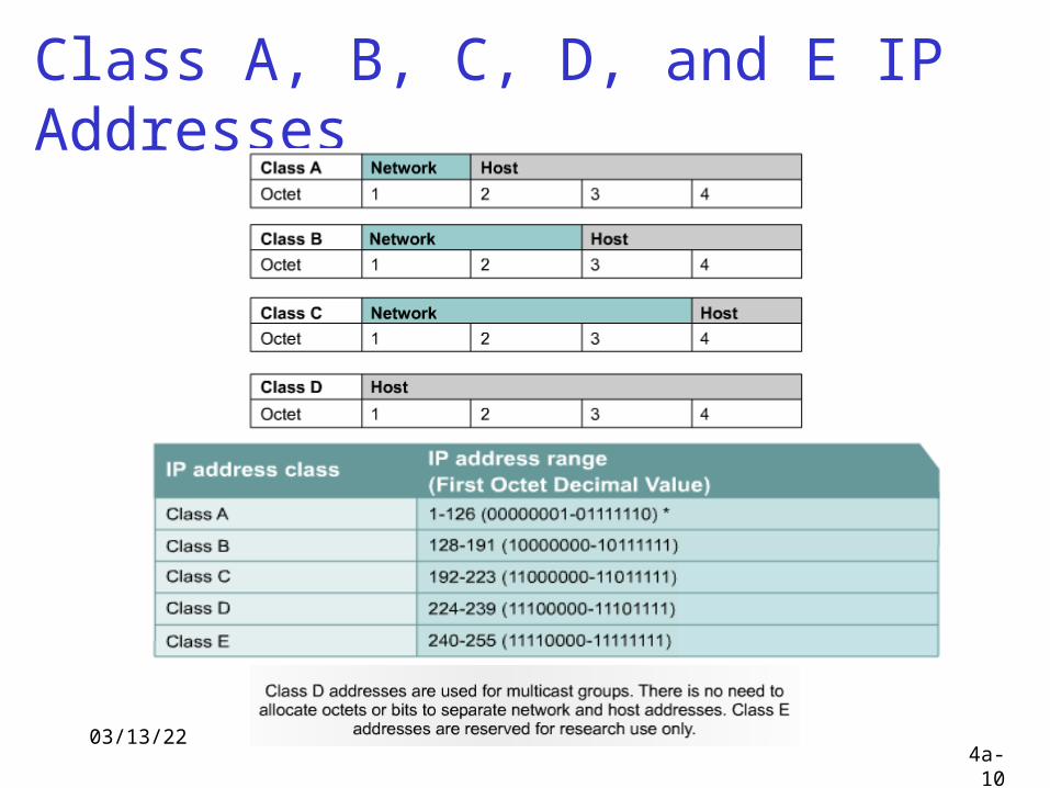
class1.0.0.0 to127.255.255.255
128.0.0.0 to191.255.255.255
192.0.0.0 to223.255.255.255
224.0.0.0 to239.255.255.255
32 bits
given notion of “network”, let’s re-examine IP addresses:
“class-full” addressing:
04/18/234a-7
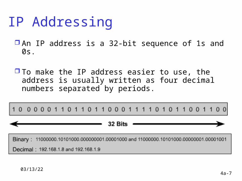
IP Addressing An IP address is a 32-bit sequence of 1s and 0s.
To make the IP address easier to use, the address is usually written as four decimal numbers separated by periods.
This way of writing the address is called the dotted decimal format.
04/18/234a-8
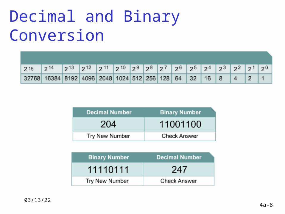
Decimal and Binary Conversion
04/18/234a-9
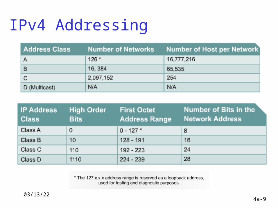
IPv4 Addressing
04/18/234a-10
Class A, B, C, D, and E IP Addresses
04/18/234a-11
04/18/234a-12
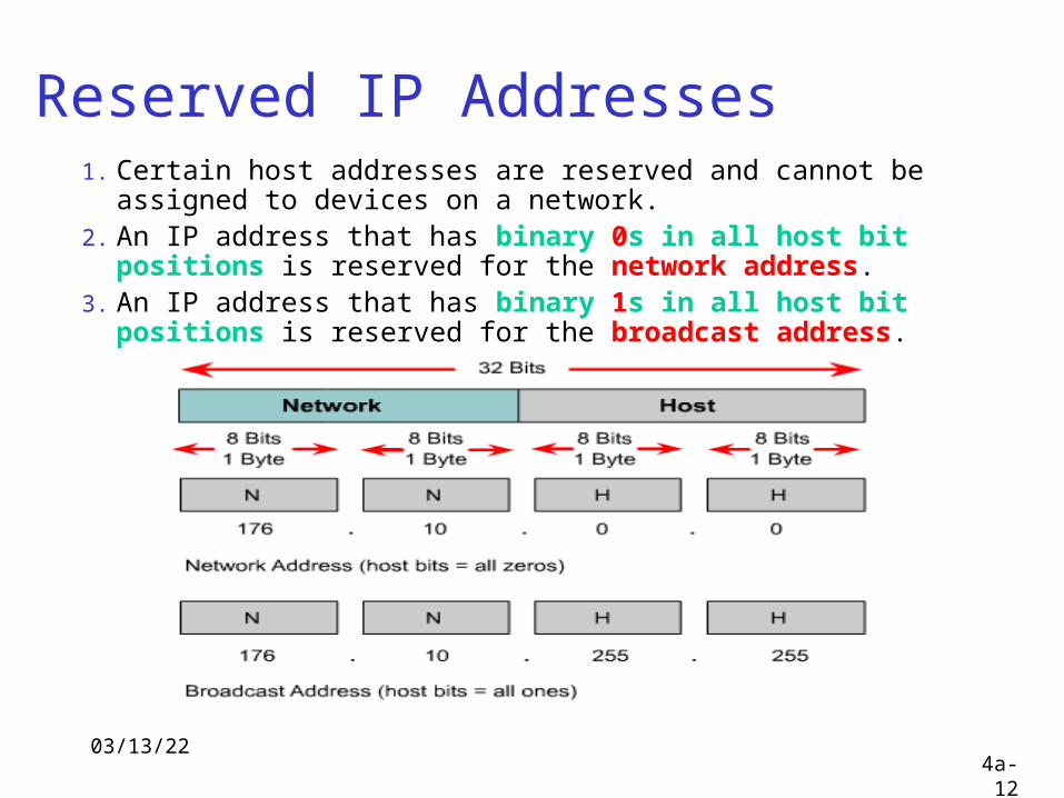
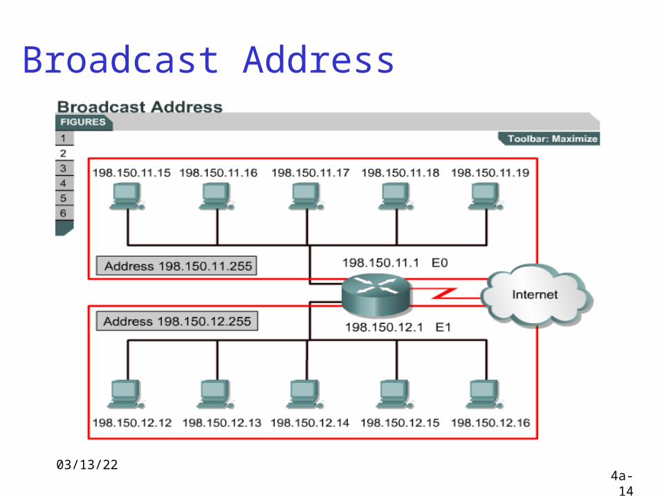
Reserved IP Addresses 1. Certain host addresses are reserved and cannot be assigned
to devices on a network. 2. An IP address that has binary 0s in all host bit positions
is reserved for the network address. 3. An IP address that has binary 1s in all host bit positions
is reserved for the broadcast address.
04/18/234a-13
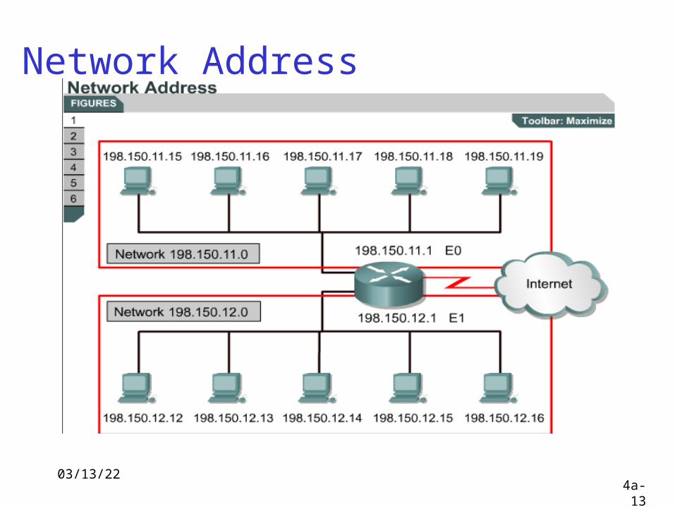
Network Address
04/18/234a-14
Broadcast Address
04/18/234a-15
Public and Private IP Addresses 1. No two machines that connect to a public network can have the same IP
address because public IP addresses are global and standardized.
2. Procedure was needed to make sure that addresses were in fact unique.
3. Originally, an organization known as the Internet Network Information Center (InterNIC) handled this procedure. InterNIC no longer exists and has been succeeded by the Internet Assigned Numbers Authority (IANA).
4. IANA carefully manages the remaining supply of IP addresses to ensure that duplication of publicly used addresses does not occur.
5. However, private networks that are not connected to the Internet may use any host addresses, as long as each host within the private network is unique.
04/18/234a-16
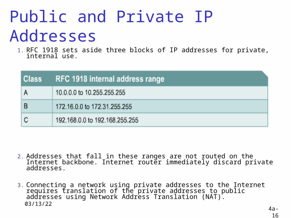
Public and Private IP Addresses 1. RFC 1918 sets aside three blocks of IP addresses for private,
internal use.
2. Addresses that fall in these ranges are not routed on the Internet backbone. Internet router immediately discard private addresses.
3. Connecting a network using private addresses to the Internet requires translation of the private addresses to public addresses using Network Address Translation (NAT).
04/18/234a-17
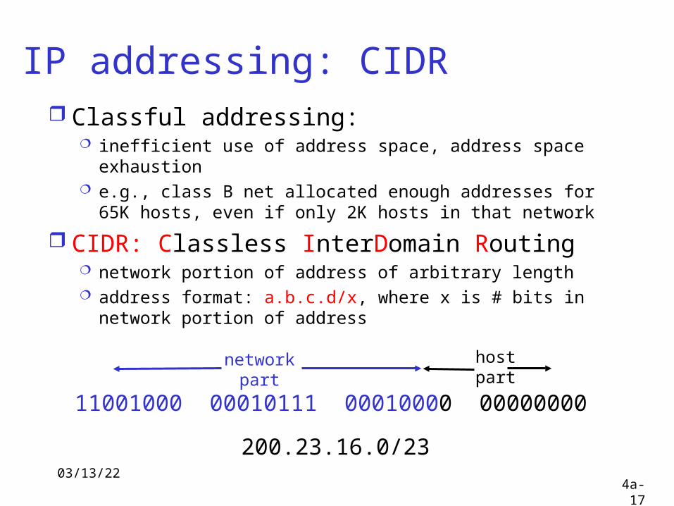
IP addressing: CIDR Classful addressing:
inefficient use of address space, address space exhaustion
e.g., class B net allocated enough addresses for 65K hosts, even if only 2K hosts in that network
CIDR: Classless InterDomain Routing network portion of address of arbitrary length address format: a.b.c.d/x, where x is # bits in network
portion of address
11001000 00010111 00010000 00000000
networkpart
hostpart
200.23.16.0/23
04/18/234a-18
Millions of Addresses Available Over 16,000,000
Efficiency Non-subnetted networks are wasteful Division of networks not optimal
Smaller Network Easier to manage Smaller broadcast domains
So Make the network as small as possible Divide the network into subnetworks Borrow some bits from the host add.
Why Subnet?

04/18/234a-19
What You Need Understand Address System Understand Classes of Networks “Two-Tums” Table
Formulas Magic Numbers Subnet Mask
“ANDing” Process
04/18/234a-20
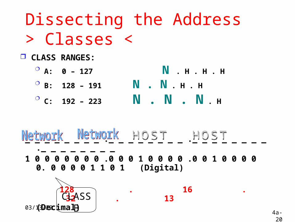
Dissecting the Address> Classes <
CLASS RANGES: A: 0 – 127 N . H . H . H
B: 128 – 191 N . N . H . H
C: 192 – 223 N . N . N . H
_ _ _ _ _ _ _ _ ._ _ _ _ _ _ _ _ ._ _ _ _ _ _ _ _ ._ _ _ _ _ _ _ _ 1 0 0 0 0 0 0 0 .0 0 0 1 0 0 0 0 .0 0 1 0 0 0 0 0. 0 0 0 0 1 1 0 1 (Digital)
128 . 16 . 32 . 13 (Decimal)
CLASSB

04/18/234a-21
TWO-TUMS
27 26 25 24 23 22 21 20
128 192 224 240 248 252 254 255
128 64 32 16 8 4 2 1
MAGIC NUMBERS:
SUBNET MASK:
04/18/234a-22
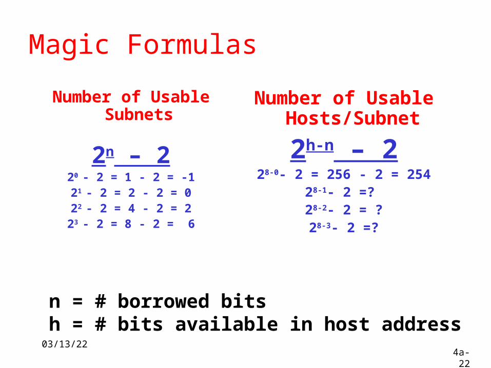
Magic Formulas
Number of Usable Subnets
2n – 220 - 2 = 1 - 2 = -121 - 2 = 2 - 2 = 022 - 2 = 4 - 2 = 223 - 2 = 8 - 2 = 6
Number of Usable Hosts/Subnet
2h-n – 228-0- 2 = 256 - 2 = 254
28-1- 2 =? 28-2- 2 = ?28-3- 2 =?
n = # borrowed bitsh = # bits available in host address
04/18/234a-23
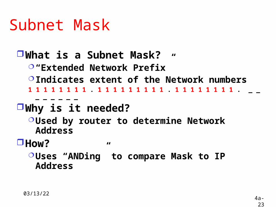
Subnet Mask
What is a Subnet Mask?“Extended Network Prefix”Indicates extent of the Network numbers1 1 1 1 1 1 1 1 . 1 1 1 1 1 1 1 1 1 . 1 1 1 1 1 1 1 1 . _ _ _ _ _ _ _ _
Why is it needed?Used by router to determine Network
AddressHow?
Uses “ANDing” to compare Mask to IP Address

04/18/234a-24
ANDing Process
MASK: 11111111.11111111.11111111.00000000
255 . 255 . 255 . 0
IP: 11001000.11001000.11001000.00001010
200 . 200 . 200 . 10
Network Address: 11001000.11001000.11001000.00000000
200 . 200 . 200 . 0
04/18/234a-25
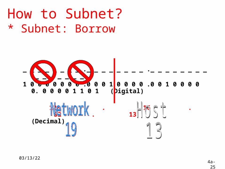
How to Subnet?* Subnet: Borrow
_ _ _ _ _ _ _ _ ._ _ _ _ _ _ _ _ ._ _ _ _ _ _ _ _ ._ _ _ _ _ _ _ _ 1 0 0 0 0 0 0 0 .0 0 0 1 0 0 0 0 .0 0 1 0 0 0 0 0. 0 0 0 0 1 1 0 1 (Digital)
128 . 16 . 32 . 13 (Decimal)

04/18/234a-26
Easy Example
04/18/234a-27
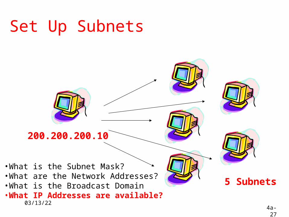
Set Up Subnets
200.200.200.10
5 Subnets
•What is the Subnet Mask?•What are the Network Addresses?•What is the Broadcast Domain•What IP Addresses are available?
04/18/234a-28
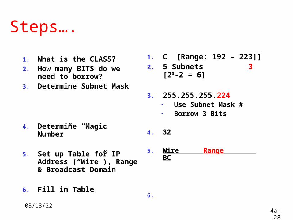
Steps….
1. What is the CLASS?2. How many BITS do we
need to borrow?3. Determine Subnet Mask
4. Determine “Magic Number”
5. Set up Table for IP Address (“Wire”), Range & Broadcast Domain
6. Fill in Table
1. C [Range: 192 – 223]]2. 5 Subnets 3 [23-2 =
6]
3. 255.255.255.224• Use Subnet Mask #• Borrow 3 Bits
4. 32
5. Wire Range BC
6.
04/18/234a-29
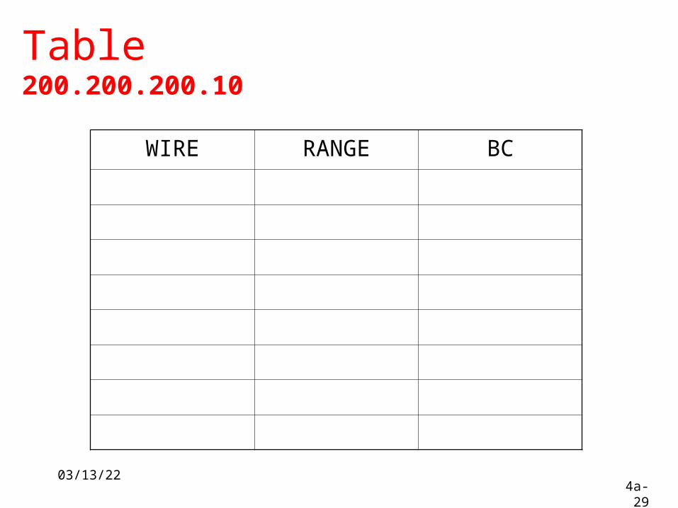
Table200.200.200.10
WIRE RANGE BC
04/18/234a-30
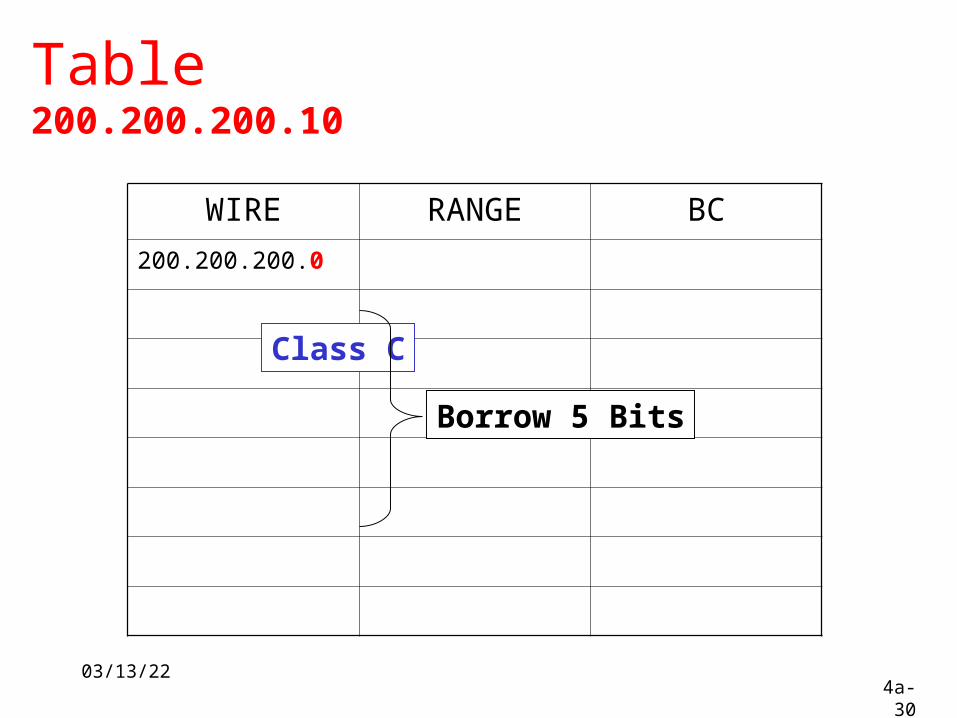
Table200.200.200.10
WIRE RANGE BC
200.200.200.0
Class C
Borrow 5 Bits
04/18/234a-31
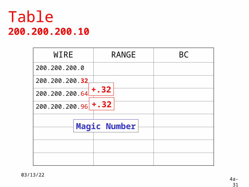
Table200.200.200.10
WIRE RANGE BC
200.200.200.0
200.200.200.32
200.200.200.64
200.200.200.96
+.32
+.32
Magic Number
04/18/234a-32
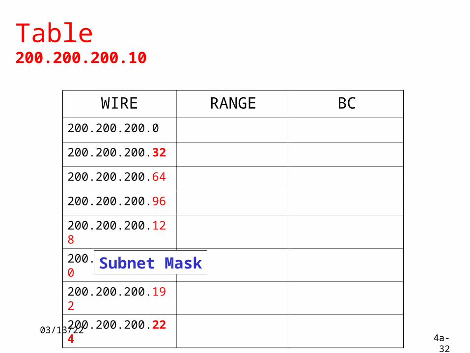
Table200.200.200.10
WIRE RANGE BC
200.200.200.0
200.200.200.32
200.200.200.64
200.200.200.96
200.200.200.128
200.200.200.160
200.200.200.192
200.200.200.224
Subnet Mask

04/18/234a-33
Table200.200.200.10
WIRE RANGE BC
200.200.200.0 200.200.200.31
200.200.200.32 200.200.200.63
200.200.200.64
200.200.200.96
200.200.200.128
200.200.200.160
200.200.200.192
200.200.200.224
04/18/234a-34
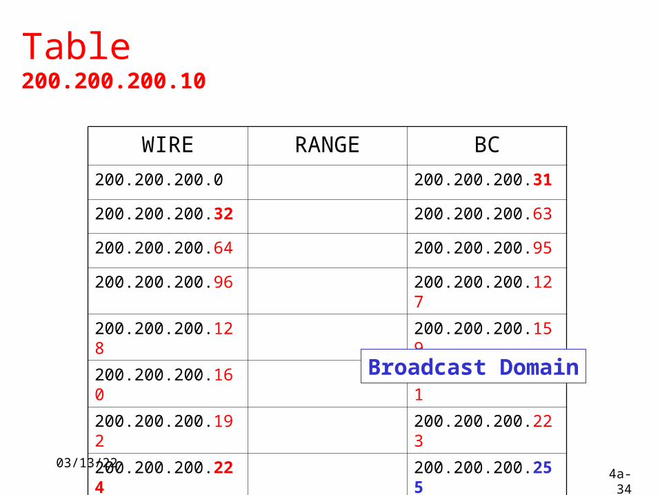
Table200.200.200.10
WIRE RANGE BC
200.200.200.0 200.200.200.31
200.200.200.32 200.200.200.63
200.200.200.64 200.200.200.95
200.200.200.96 200.200.200.127
200.200.200.128 200.200.200.159
200.200.200.160 200.200.200.191
200.200.200.192 200.200.200.223
200.200.200.224 200.200.200.255
Broadcast Domain
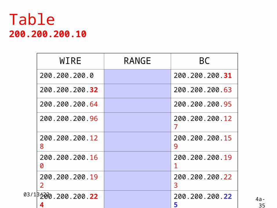
04/18/234a-35
Table200.200.200.10
WIRE RANGE BC
200.200.200.0 200.200.200.31
200.200.200.32 200.200.200.63
200.200.200.64 200.200.200.95
200.200.200.96 200.200.200.127
200.200.200.128 200.200.200.159
200.200.200.160 200.200.200.191
200.200.200.192 200.200.200.223
200.200.200.224 200.200.200.225
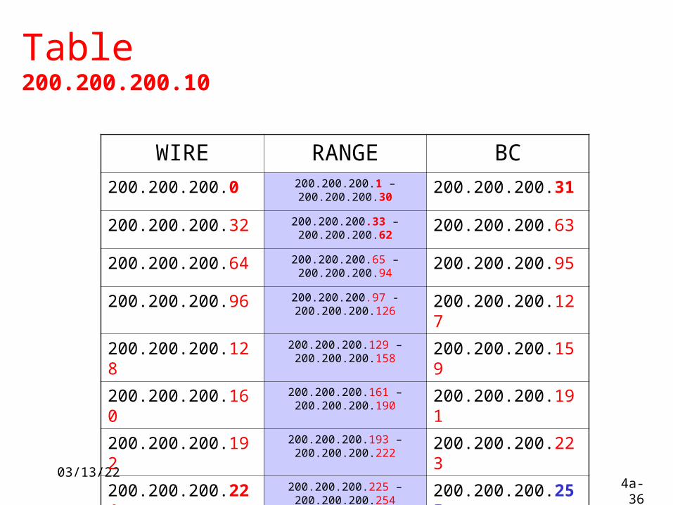
04/18/234a-36
Table200.200.200.10
WIRE RANGE BC200.200.200.0 200.200.200.1 –
200.200.200.30200.200.200.31
200.200.200.32 200.200.200.33 – 200.200.200.62
200.200.200.63
200.200.200.64 200.200.200.65 – 200.200.200.94
200.200.200.95
200.200.200.96 200.200.200.97 - 200.200.200.126
200.200.200.127
200.200.200.128 200.200.200.129 – 200.200.200.158
200.200.200.159
200.200.200.160 200.200.200.161 – 200.200.200.190
200.200.200.191
200.200.200.192 200.200.200.193 – 200.200.200.222
200.200.200.223
200.200.200.224 200.200.200.225 – 200.200.200.254
200.200.200.255
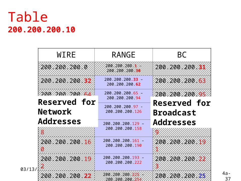
04/18/234a-37
Table200.200.200.10
WIRE RANGE BC200.200.200.0 200.200.200.1 –
200.200.200.30200.200.200.31
200.200.200.32 200.200.200.33 – 200.200.200.62
200.200.200.63
200.200.200.64 200.200.200.65 – 200.200.200.94
200.200.200.95
200.200.200.96 200.200.200.97 - 200.200.200.126
200.200.200.127
200.200.200.128 200.200.200.129 – 200.200.200.158
200.200.200.159
200.200.200.160 200.200.200.161 – 200.200.200.190
200.200.200.191
200.200.200.192 200.200.200.193 – 200.200.200.222
200.200.200.223
200.200.200.224 200.200.200.225 – 200.200.200.254
200.200.200.255
Reserved forNetwork Addresses
Reserved forBroadcastAddresses

04/18/234a-38
Table200.200.200.10
WIRE RANGE BC
200.200.200.33 – 200.200.200.62
200.200.200.65 – 200.200.200.94
200.200.200.97 - 200.200.200.126
200.200.200.129 – 200.200.200.158
200.200.200.161 – 200.200.200.190
200.200.200.193 – 200.200.200.222
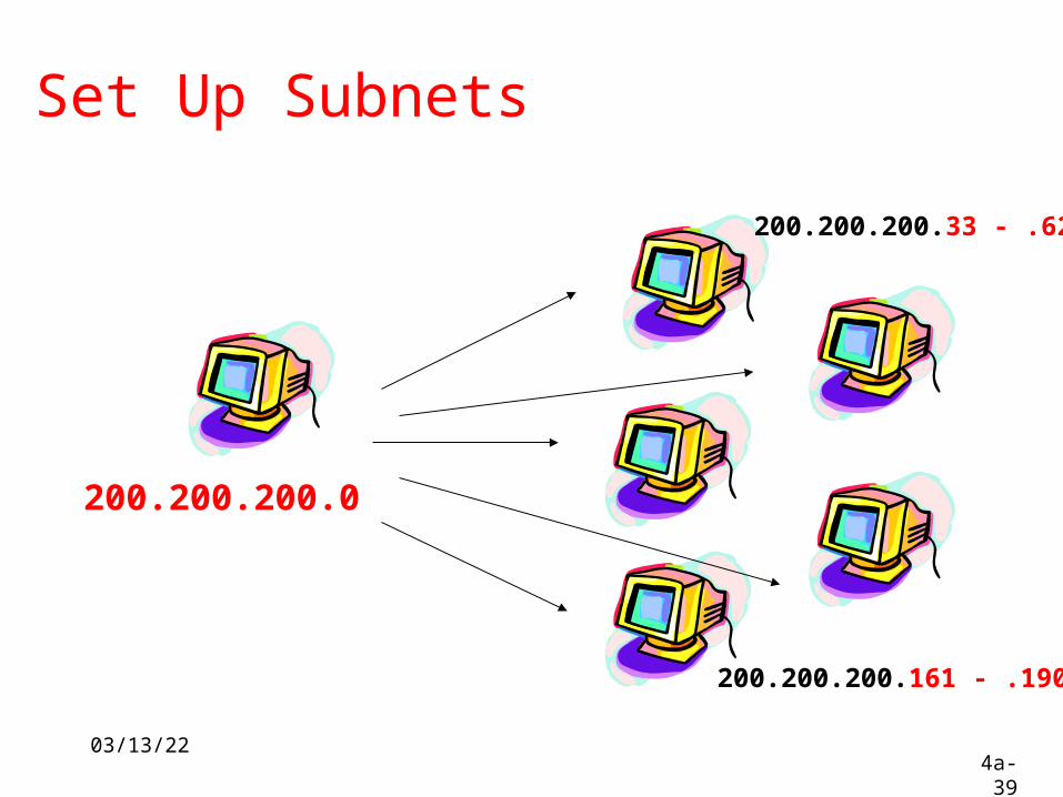
04/18/234a-39
Set Up Subnets
200.200.200.0
200.200.200.33 - .62
200.200.200.161 - .190

04/18/234a-40

04/18/234a-41
Obtaining an Internet Address
1.Static addressing Each individual device must be configured
with an IP address.
2.Dynamic addressing Reverse Address Resolution Protocol (RARP) Bootstrap Protocol (BOOTP) Dynamic Host Configuration Protocol (DHCP) DHCP initialization sequence Function of the Address Resolution Protocol ARP operation within a subnet
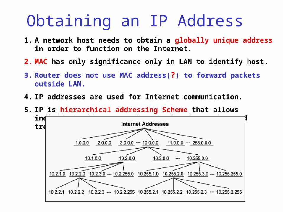
Obtaining an IP Address1. A network host needs to obtain a globally unique address in
order to function on the Internet.
2. MAC has only significance only in LAN to identify host.
3. Router does not use MAC address(?) to forward packets outside LAN.
4. IP addresses are used for Internet communication.
5. IP is hierarchical addressing Scheme that allows individual addresses to be associated together and treated together.
04/18/234a-43
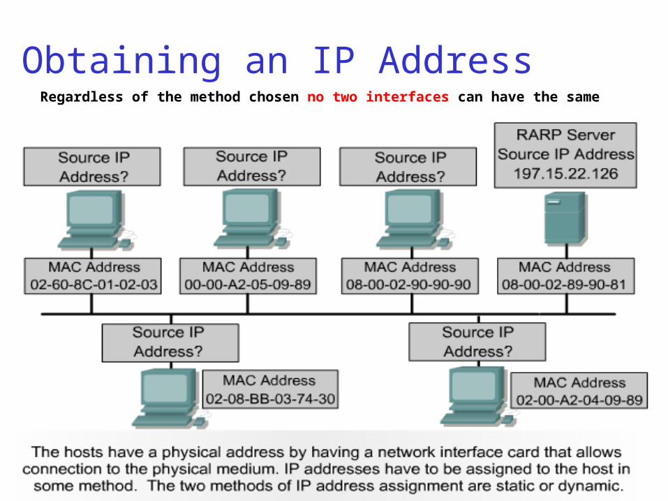
Obtaining an IP AddressRegardless of the method chosen no two interfaces can have the same IP
address.
04/18/234a-44
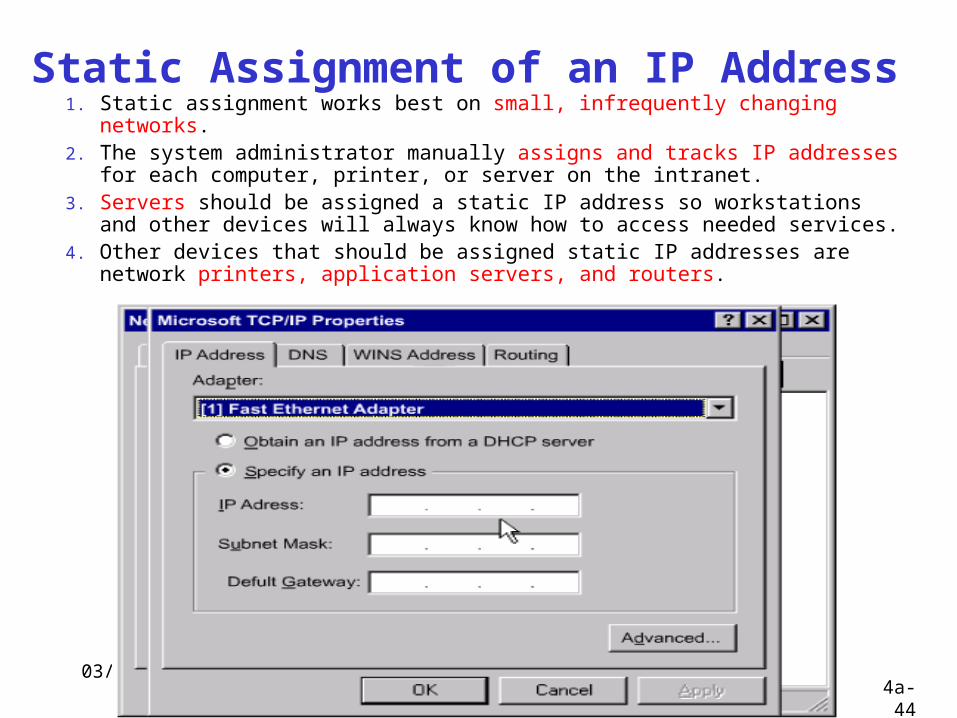
Static Assignment of an IP Address 1. Static assignment works best on small, infrequently changing
networks. 2. The system administrator manually assigns and tracks IP addresses
for each computer, printer, or server on the intranet. 3. Servers should be assigned a static IP address so workstations and
other devices will always know how to access needed services. 4. Other devices that should be assigned static IP addresses are network
printers, application servers, and routers.
04/18/234a-45
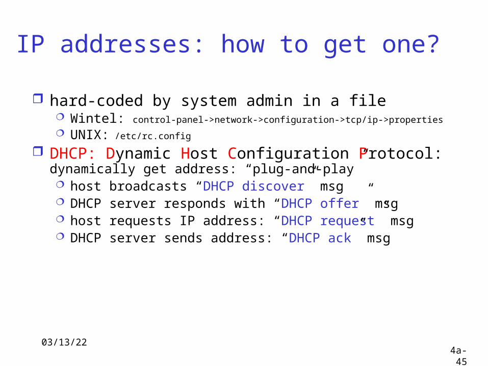
IP addresses: how to get one?
hard-coded by system admin in a file Wintel: control-panel->network->configuration->tcp/ip->properties
UNIX: /etc/rc.config
DHCP: Dynamic Host Configuration Protocol: dynamically get address: “plug-and-play” host broadcasts “DHCP discover” msg DHCP server responds with “DHCP offer” msg host requests IP address: “DHCP request” msg DHCP server sends address: “DHCP ack” msg
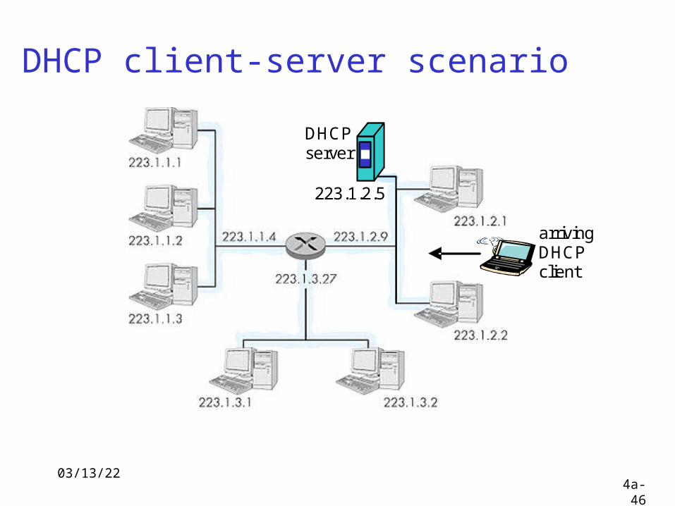
04/18/234a-46
DHCP client-server scenario
DHCP server
arriving DHCP client
223.1.2.5
Figure 4.4.2-N1: DHCP client-server scenario

04/18/234a-47
DHCP client-server scenario
DHCP server: 223.1.2.5 arriving client
time
DHCP discoversrc : 0.0.0.0, 68 dest.: 255.255.255.255,67DHCPDISCOVERyiaddr: 0.0.0.0transaction ID: 654
DHCP offersrc: 223.1.2.5, 67 dest: 223.1.2.4, 68DHCPOFFERyiaddrr: 223.1.2.4transaction ID: 654DHCP server ID: 223.1.2.5Lifetime: 3600 secs
DHCP requestsrc: 0.0.0.0, 68 dest:: 255.255.255.255, 67DHCPREQUESTyiaddrr: 223.1.2.4transaction ID: 655DHCP server ID: 223.1.2.5Lifetime: 3600 secs
DHCP ACKsrc: 223.1.2.5, 67 dest: 223.1.2.4, 68DHCPACKyiaddrr: 223.1.2.4transaction ID: 655DHCP server ID: 223.1.2.5Lifetime: 3600 secs
04/18/234a-48
DHCP IP Address Management • DHCP allows a host to obtain an IP address dynamically without the
network administrator having to set up an individual profile for each device.
• All that is required when using DHCP is a defined range of IP addresses on a DHCP server.
• As hosts come online, they contact the DHCP server and request an address.
• The DHCP server chooses an address and leases it to that host. • With DHCP, the entire network configuration of a computer can be
obtained in one message. • The major advantage that DHCP has over BOOTP is that it allows users to
be mobile. • This mobility allows the users to freely change network connections from
location to location. • The importance to this DHCP advancement is its ability to lease an IP
address to a device and then reclaim that IP address for another user after the first user releases it.
• This means that DHCP offers a one to many ratio of IP addresses and that an address is available to anyone who connects to the network.
04/18/234a-49
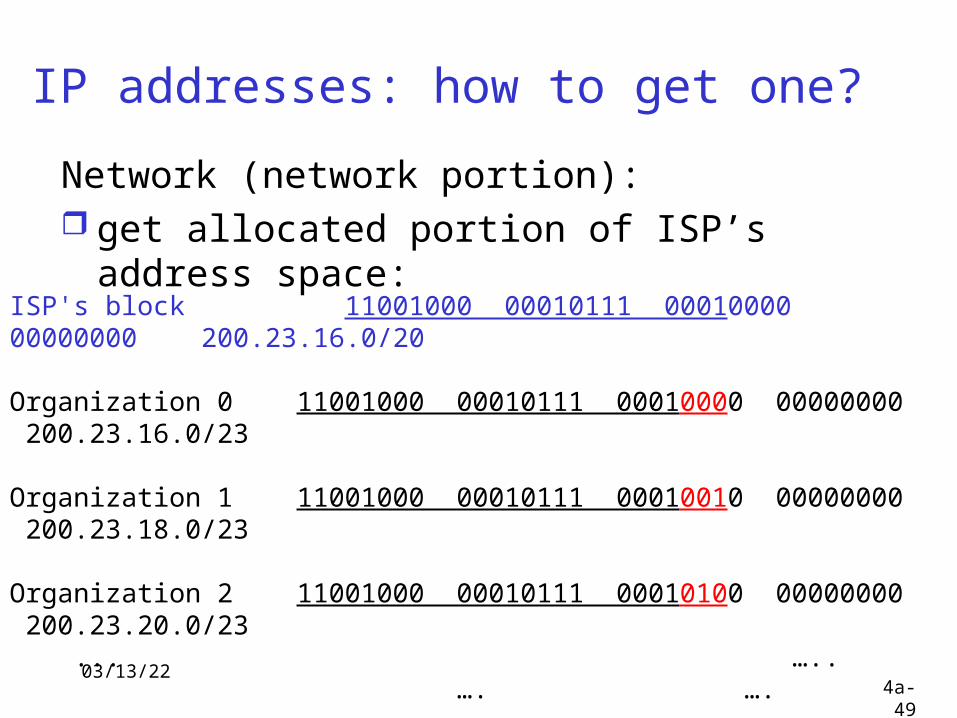
IP addresses: how to get one?
Network (network portion): get allocated portion of ISP’s address
space:ISP's block 11001000 00010111 00010000 00000000 200.23.16.0/20
Organization 0 11001000 00010111 00010000 00000000 200.23.16.0/23
Organization 1 11001000 00010111 00010010 00000000 200.23.18.0/23
Organization 2 11001000 00010111 00010100 00000000 200.23.20.0/23 ... ….. …. ….
Organization 7 11001000 00010111 00011110 00000000 200.23.30.0/23
04/18/234a-50
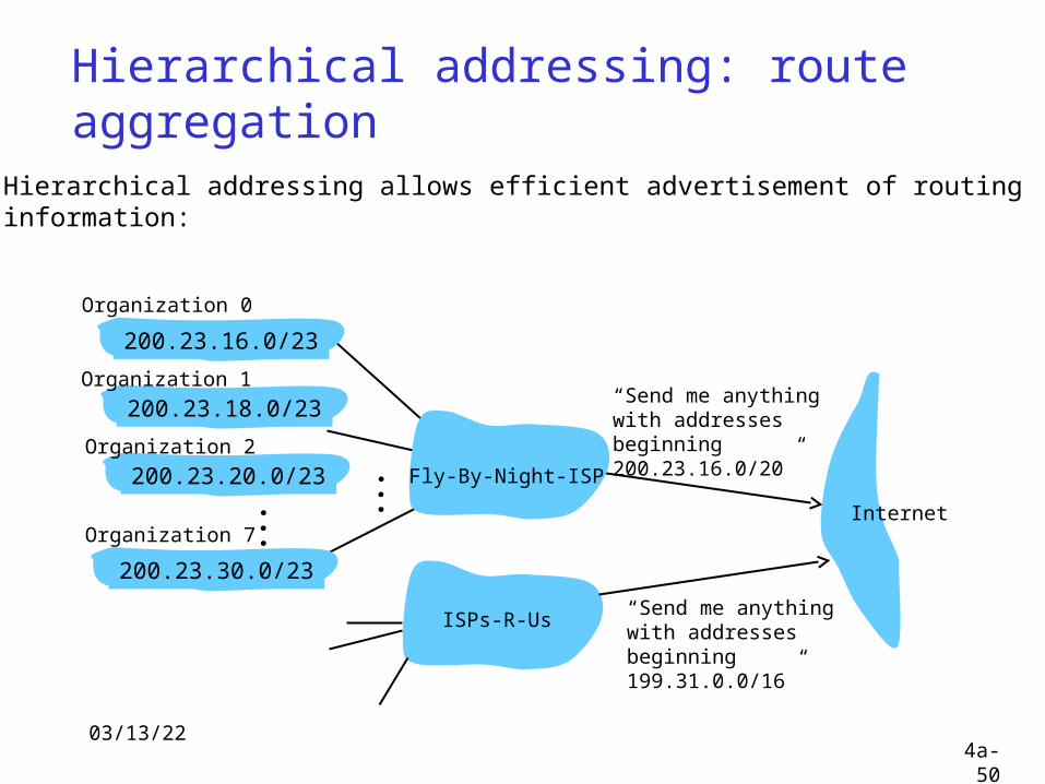
Hierarchical addressing: route aggregation
“Send me anythingwith addresses beginning 200.23.16.0/20”
200.23.16.0/23
200.23.18.0/23
200.23.30.0/23
Fly-By-Night-ISP
Organization 0
Organization 7Internet
Organization 1
ISPs-R-Us“Send me anythingwith addresses beginning 199.31.0.0/16”
200.23.20.0/23Organization 2
...
...
Hierarchical addressing allows efficient advertisement of routing information:
04/18/234a-51
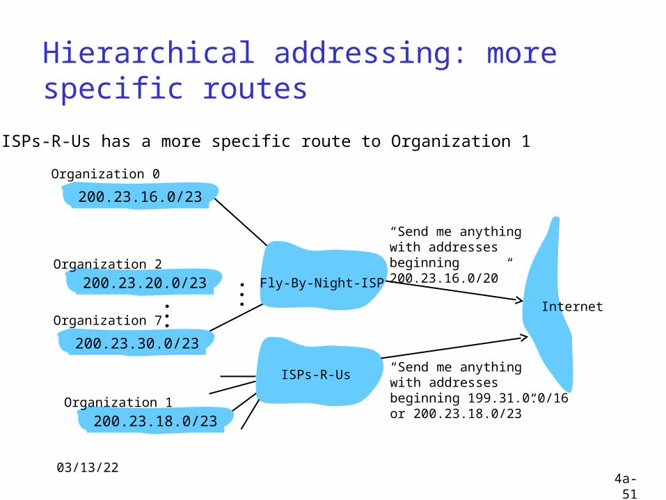
Hierarchical addressing: more specific routes
ISPs-R-Us has a more specific route to Organization 1
“Send me anythingwith addresses beginning 200.23.16.0/20”
200.23.16.0/23
200.23.18.0/23
200.23.30.0/23
Fly-By-Night-ISP
Organization 0
Organization 7Internet
Organization 1
ISPs-R-Us“Send me anythingwith addresses beginning 199.31.0.0/16or 200.23.18.0/23”
200.23.20.0/23Organization 2
...
...
04/18/234a-52
IP addressing: the last word...
Q: How does an ISP get block of addresses?
A: ICANN: Internet Corporation for Assigned
Names and Numbers allocates addresses manages DNS assigns domain names, resolves disputes

04/18/234a-53

04/18/234a-54
04/18/234a-55
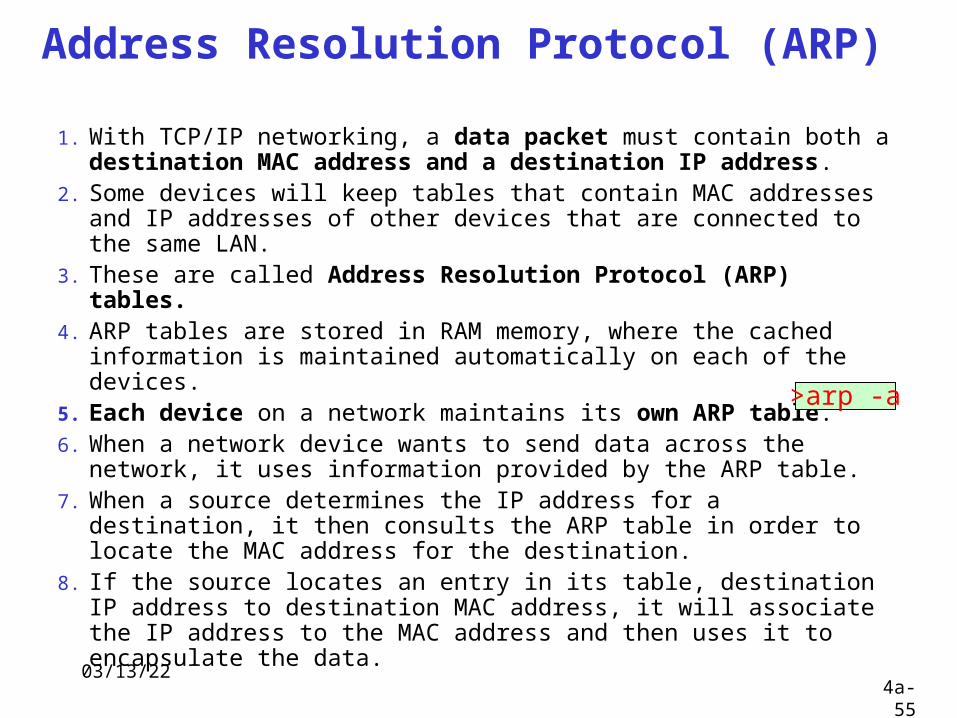
Address Resolution Protocol (ARP)
1. With TCP/IP networking, a data packet must contain both a destination MAC address and a destination IP address.
2. Some devices will keep tables that contain MAC addresses and IP addresses of other devices that are connected to the same LAN.
3. These are called Address Resolution Protocol (ARP) tables. 4. ARP tables are stored in RAM memory, where the cached
information is maintained automatically on each of the devices. 5. Each device on a network maintains its own ARP table. 6. When a network device wants to send data across the network, it
uses information provided by the ARP table. 7. When a source determines the IP address for a destination, it
then consults the ARP table in order to locate the MAC address for the destination.
8. If the source locates an entry in its table, destination IP address to destination MAC address, it will associate the IP address to the MAC address and then uses it to encapsulate the data.
>arp -a
04/18/234a-56
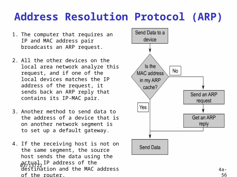
Address Resolution Protocol (ARP) 1. The computer that requires an IP and
MAC address pair broadcasts an ARP request.
2. All the other devices on the local area network analyze this request, and if one of the local devices matches the IP address of the request, it sends back an ARP reply that contains its IP-MAC pair.
3. Another method to send data to the address of a device that is on another network segment is to set up a default gateway.
4. If the receiving host is not on the same segment, the source host sends the data using the actual IP address of the destination and the MAC address of the router.
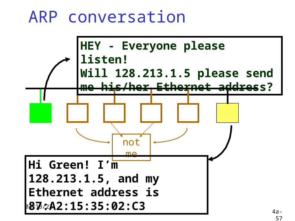
04/18/234a-57
ARP conversation
HEY - Everyone please listen! Will 128.213.1.5 please send me his/her Ethernet address?
not me
Hi Green! I’m 128.213.1.5, and my Ethernet address is 87:A2:15:35:02:C3

04/18/234a-58
RARP conversation
HEY - Everyone please listen! My Ethernet address is 22:BC:66:17:01:75.Does anyone know my IP address ?
not me
Hi Green! Your IP address is 128.213.1.17.
04/18/234a-59
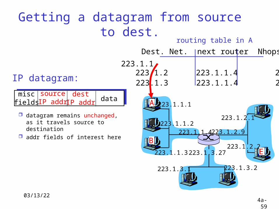
Getting a datagram from source to dest.
IP datagram:
223.1.1.1
223.1.1.2
223.1.1.3
223.1.1.4 223.1.2.9
223.1.2.2
223.1.2.1
223.1.3.2223.1.3.1
223.1.3.27
A
BE
miscfields
sourceIP addr
destIP addr data
datagram remains unchanged, as it travels source to destination
addr fields of interest here
Dest. Net. next router Nhops
223.1.1 1223.1.2 223.1.1.4 2223.1.3 223.1.1.4 2
routing table in A
04/18/234a-60
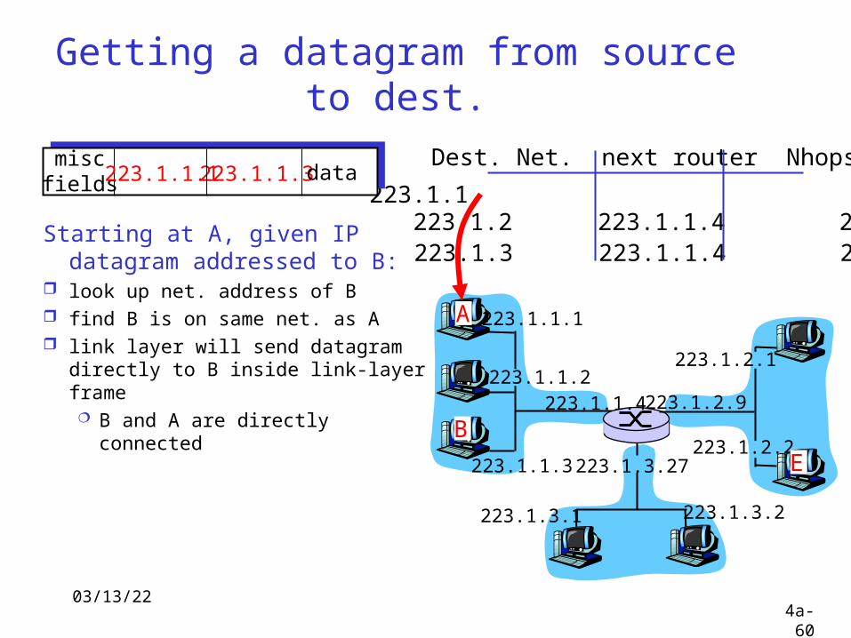
Getting a datagram from source to dest.
Starting at A, given IP datagram addressed to B:
look up net. address of B find B is on same net. as A link layer will send datagram
directly to B inside link-layer frame B and A are directly connected
Dest. Net. next router Nhops
223.1.1 1223.1.2 223.1.1.4 2223.1.3 223.1.1.4 2
miscfields223.1.1.1223.1.1.3data
223.1.1.1
223.1.1.2
223.1.1.3
223.1.1.4 223.1.2.9
223.1.2.2
223.1.2.1
223.1.3.2223.1.3.1
223.1.3.27
A
BE
04/18/234a-61
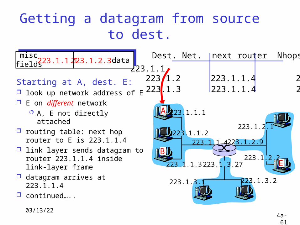
Getting a datagram from source to dest.
Dest. Net. next router Nhops
223.1.1 1223.1.2 223.1.1.4 2223.1.3 223.1.1.4 2
Starting at A, dest. E: look up network address of E E on different network
A, E not directly attached routing table: next hop router
to E is 223.1.1.4 link layer sends datagram to
router 223.1.1.4 inside link-layer frame
datagram arrives at 223.1.1.4 continued…..
miscfields223.1.1.1223.1.2.3 data
223.1.1.1
223.1.1.2
223.1.1.3
223.1.1.4 223.1.2.9
223.1.2.2
223.1.2.1
223.1.3.2223.1.3.1
223.1.3.27
A
BE
04/18/234a-62
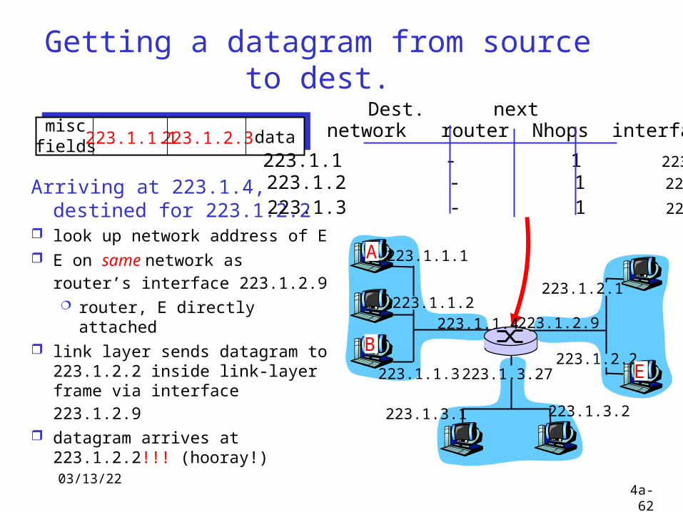
Getting a datagram from source to dest.
Arriving at 223.1.4, destined for 223.1.2.2
look up network address of E E on same network as
router’s interface 223.1.2.9 router, E directly
attached link layer sends datagram to
223.1.2.2 inside link-layer frame via interface 223.1.2.9
datagram arrives at 223.1.2.2!!! (hooray!)
miscfields223.1.1.1223.1.2.3 data network router Nhops interface
223.1.1 - 1 223.1.1.4 223.1.2 - 1 223.1.2.9
223.1.3 - 1 223.1.3.27
Dest. next
223.1.1.1
223.1.1.2
223.1.1.3
223.1.1.4 223.1.2.9
223.1.2.2
223.1.2.1
223.1.3.2223.1.3.1
223.1.3.27
A
BE
04/18/234a-63
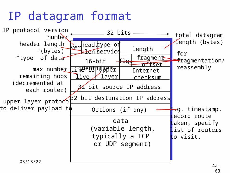
IP datagram format
ver length
32 bits
data (variable length,typically a TCP
or UDP segment)
16-bit identifier
Internet checksum
time tolive
32 bit source IP address
IP protocol versionnumber
header length (bytes)
max numberremaining hops
(decremented at each router)
forfragmentation/reassembly
total datagramlength (bytes)
upper layer protocolto deliver payload to
head.len
type ofservice
“type” of data flgsfragment
offsetupper layer
32 bit destination IP address
Options (if any) E.g. timestamp,record routetaken, specifylist of routers to visit.
04/18/234a-64
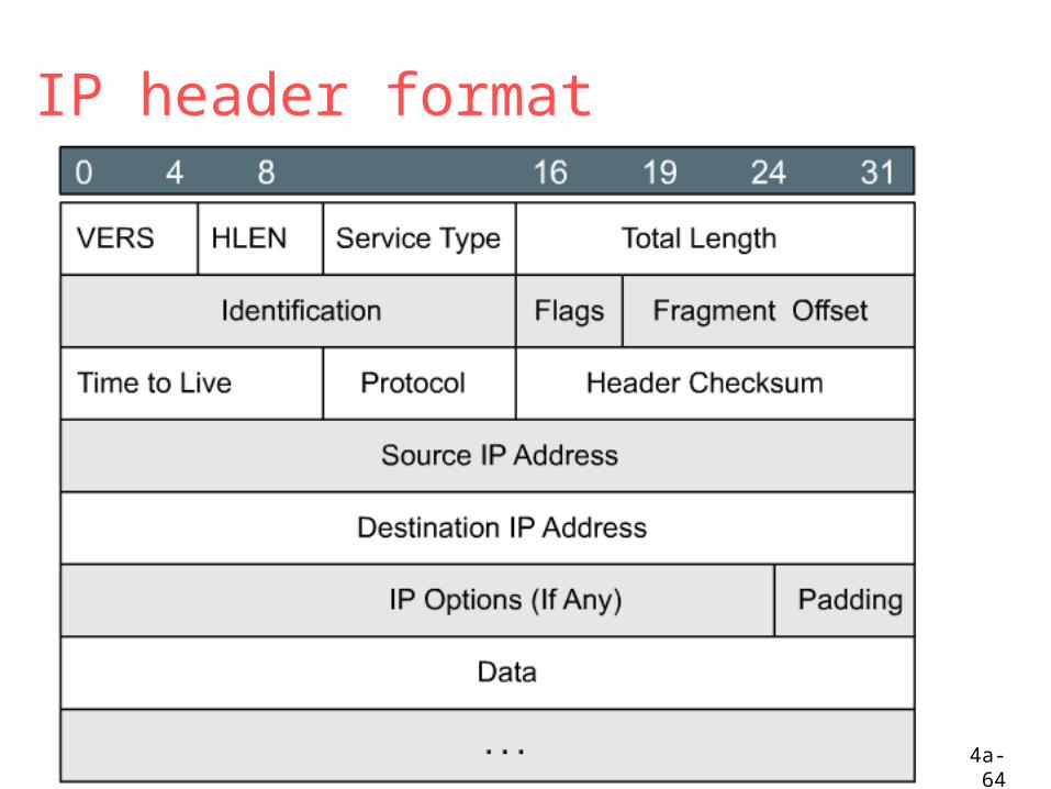
IP header format
04/18/234a-65
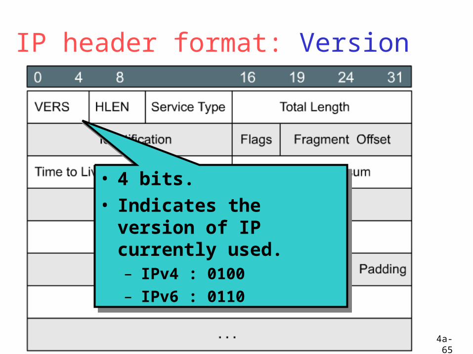
IP header format: Version
• 4 bits.• Indicates the version of
IP currently used.– IPv4 : 0100– IPv6 : 0110
• 4 bits.• Indicates the version of
IP currently used.– IPv4 : 0100– IPv6 : 0110
04/18/234a-66
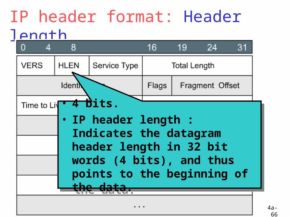
IP header format: Header length
• 4 bits.• IP header length : Indicates the
datagram header length in 32 bit words (4 bits), and thus points to the beginning of the data.
• 4 bits.• IP header length : Indicates the
datagram header length in 32 bit words (4 bits), and thus points to the beginning of the data.
04/18/234a-67
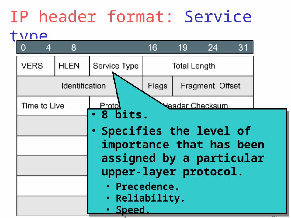
IP header format: Service type
• 8 bits.• Specifies the level of importance
that has been assigned by a particular upper-layer protocol.• Precedence. • Reliability. • Speed.
• 8 bits.• Specifies the level of importance
that has been assigned by a particular upper-layer protocol.• Precedence. • Reliability. • Speed.
04/18/234a-68
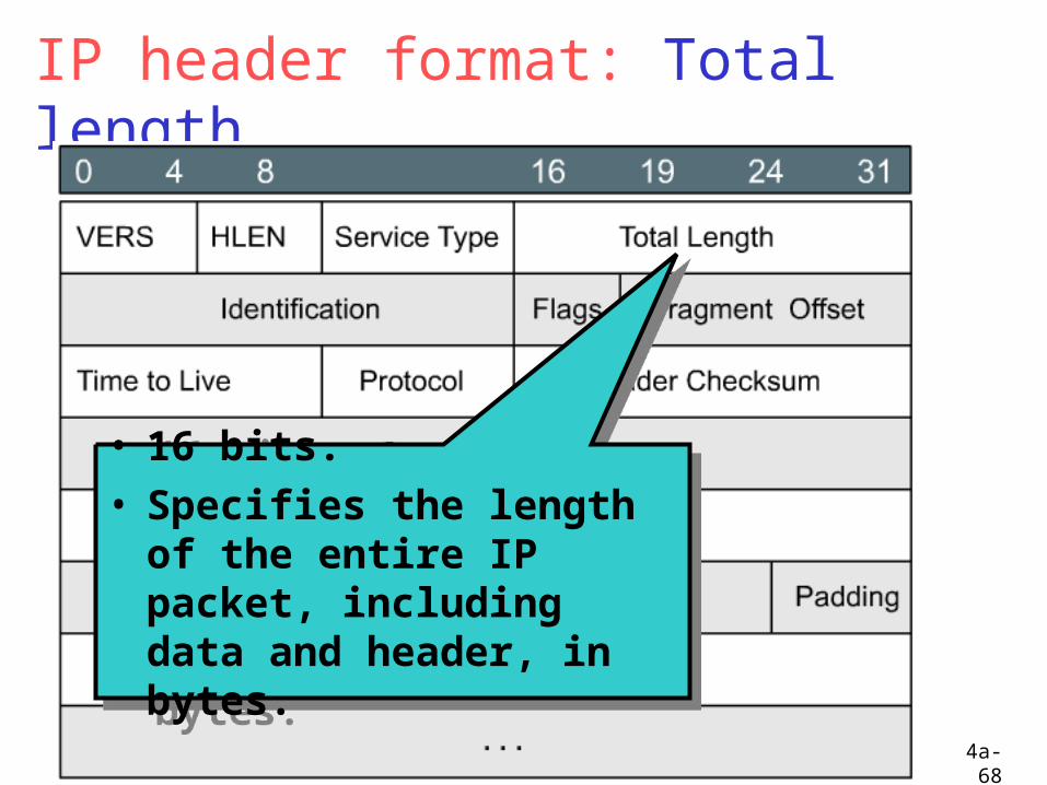
IP header format: Total length
• 16 bits.• Specifies the length of the
entire IP packet, including data and header, in bytes.
• 16 bits.• Specifies the length of the
entire IP packet, including data and header, in bytes.
04/18/234a-69
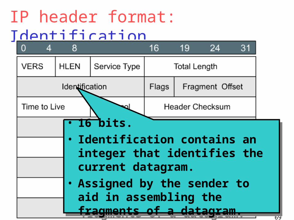
IP header format: Identification
• 16 bits.• Identification contains an integer
that identifies the current datagram.• Assigned by the sender to aid in
assembling the fragments of a datagram.
• 16 bits.• Identification contains an integer
that identifies the current datagram.• Assigned by the sender to aid in
assembling the fragments of a datagram.
04/18/234a-70
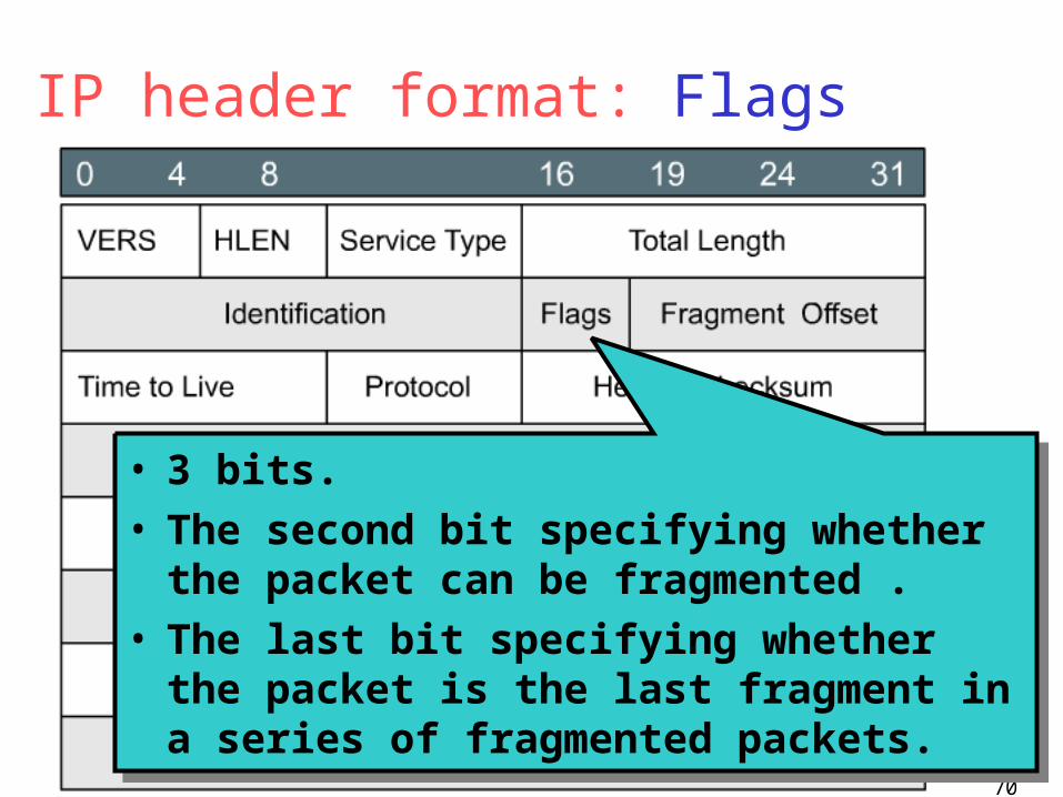
IP header format: Flags
• 3 bits.• The second bit specifying whether the
packet can be fragmented .• The last bit specifying whether the packet
is the last fragment in a series of fragmented packets.
• 3 bits.• The second bit specifying whether the
packet can be fragmented .• The last bit specifying whether the packet
is the last fragment in a series of fragmented packets.
04/18/234a-71
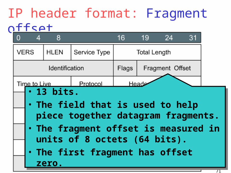
IP header format: Fragment offset
• 13 bits.• The field that is used to help piece together
datagram fragments.• The fragment offset is measured in units of
8 octets (64 bits). • The first fragment has offset zero.
• 13 bits.• The field that is used to help piece together
datagram fragments.• The fragment offset is measured in units of
8 octets (64 bits). • The first fragment has offset zero.
04/18/234a-72
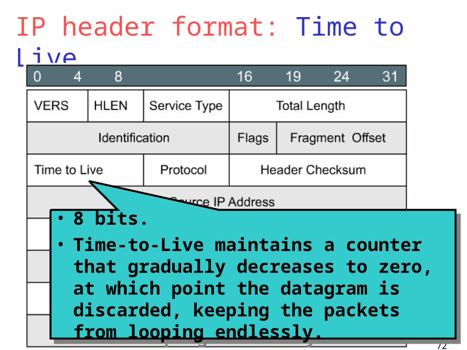
IP header format: Time to Live
• 8 bits.• Time-to-Live maintains a counter that
gradually decreases to zero, at which point the datagram is discarded, keeping the packets from looping endlessly.
• 8 bits.• Time-to-Live maintains a counter that
gradually decreases to zero, at which point the datagram is discarded, keeping the packets from looping endlessly.
04/18/234a-73
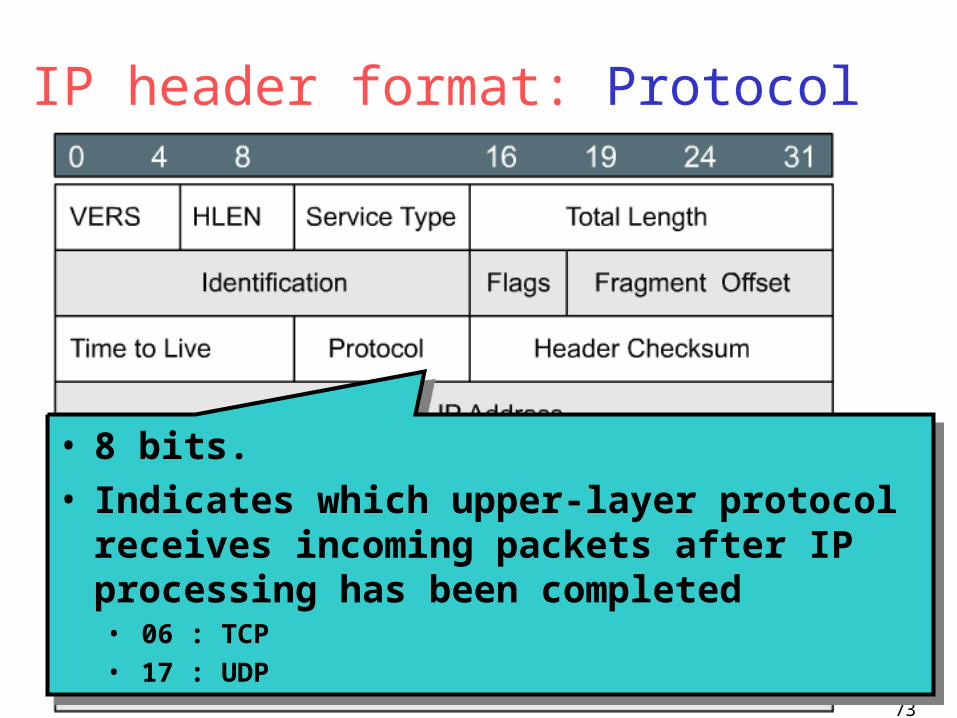
IP header format: Protocol
• 8 bits.• Indicates which upper-layer protocol receives
incoming packets after IP processing has been completed• 06 : TCP• 17 : UDP
• 8 bits.• Indicates which upper-layer protocol receives
incoming packets after IP processing has been completed• 06 : TCP• 17 : UDP
04/18/234a-74
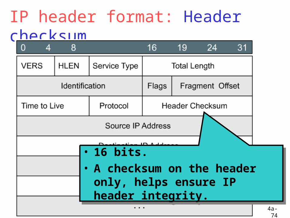
IP header format: Header checksum
• 16 bits.• A checksum on the header only,
helps ensure IP header integrity.
• 16 bits.• A checksum on the header only,
helps ensure IP header integrity.
04/18/234a-75
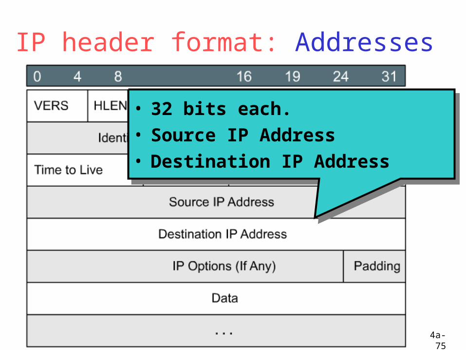
IP header format: Addresses
• 32 bits each.• Source IP Address• Destination IP Address
• 32 bits each.• Source IP Address• Destination IP Address

04/18/234a-76
IP header format: Options
• Variable length.• Allows IP to support various options,
such as security, route, error report ...
• Variable length.• Allows IP to support various options,
such as security, route, error report ...
04/18/234a-77
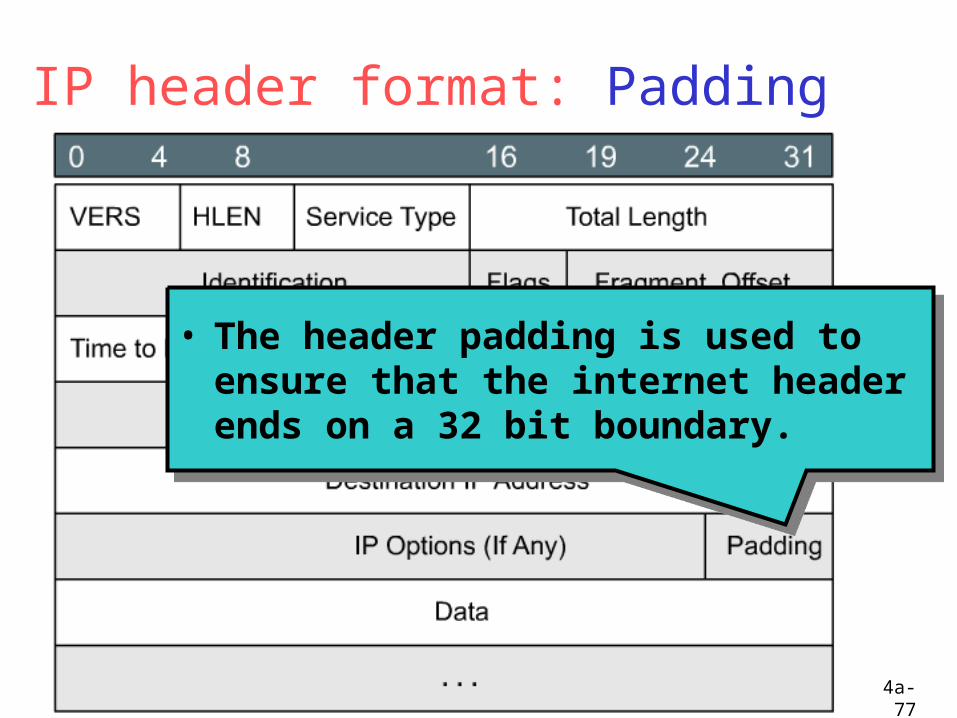
IP header format: Padding
• The header padding is used to ensure that the internet header ends on a 32 bit boundary.
• The header padding is used to ensure that the internet header ends on a 32 bit boundary.
04/18/234a-78
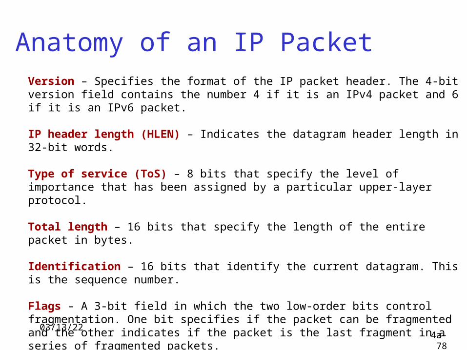
Anatomy of an IP PacketVersion – Specifies the format of the IP packet header. The 4-bit version field contains the number 4 if it is an IPv4 packet and 6 if it is an IPv6 packet.
IP header length (HLEN) – Indicates the datagram header length in 32-bit words.
Type of service (ToS) – 8 bits that specify the level of importance that has been assigned by a particular upper-layer protocol.
Total length – 16 bits that specify the length of the entire packet in bytes.
Identification – 16 bits that identify the current datagram. This is the sequence number.
Flags – A 3-bit field in which the two low-order bits control fragmentation. One bit specifies if the packet can be fragmented and the other indicates if the packet is the last fragment in a series of fragmented packets.
Fragment offset – 13 bits that are used to help piece together datagram fragments. This field allows the previous field to end on a 16-bit boundary.
04/18/234a-79
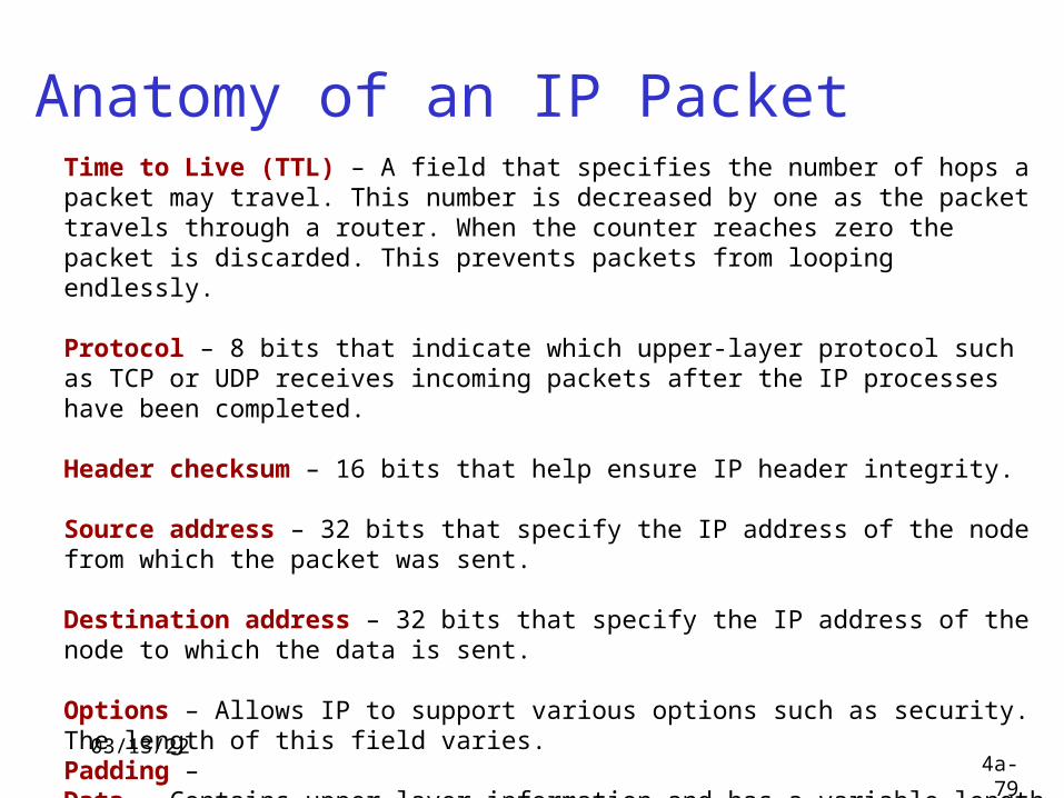
Anatomy of an IP PacketTime to Live (TTL) – A field that specifies the number of hops a packet may travel. This number is decreased by one as the packet travels through a router. When the counter reaches zero the packet is discarded. This prevents packets from looping endlessly.
Protocol – 8 bits that indicate which upper-layer protocol such as TCP or UDP receives incoming packets after the IP processes have been completed.
Header checksum – 16 bits that help ensure IP header integrity.
Source address – 32 bits that specify the IP address of the node from which the packet was sent.
Destination address – 32 bits that specify the IP address of the node to which the data is sent.
Options – Allows IP to support various options such as security. The length of this field varies. Padding –Data – Contains upper-layer information and has a variable length of up to 64 bits.
04/18/234a-80
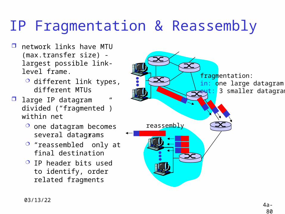
IP Fragmentation & Reassembly network links have MTU
(max.transfer size) - largest possible link-level frame. different link types,
different MTUs large IP datagram divided
(“fragmented”) within net one datagram becomes
several datagrams “reassembled” only at
final destination IP header bits used to
identify, order related fragments
fragmentation: in: one large datagramout: 3 smaller datagrams
reassembly
04/18/234a-81
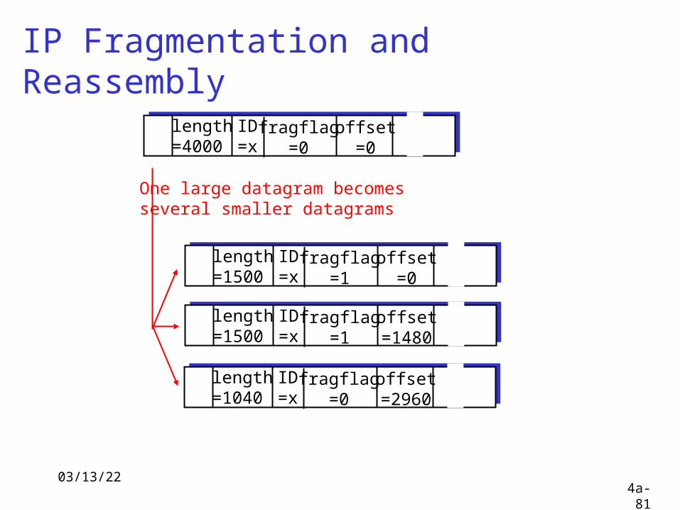
IP Fragmentation and Reassembly
ID=x
offset=0
fragflag=0
length=4000
ID=x
offset=0
fragflag=1
length=1500
ID=x
offset=1480
fragflag=1
length=1500
ID=x
offset=2960
fragflag=0
length=1040
One large datagram becomesseveral smaller datagrams
04/18/234a-82
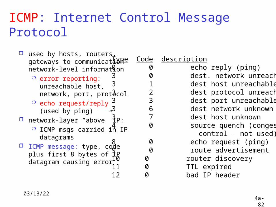
ICMP: Internet Control Message Protocol
used by hosts, routers, gateways to communication network-level information error reporting:
unreachable host, network, port, protocol
echo request/reply (used by ping)
network-layer “above” IP: ICMP msgs carried in IP
datagrams ICMP message: type, code
plus first 8 bytes of IP datagram causing error
Type Code description0 0 echo reply (ping)3 0 dest. network unreachable3 1 dest host unreachable3 2 dest protocol unreachable3 3 dest port unreachable3 6 dest network unknown3 7 dest host unknown4 0 source quench (congestion control - not used)8 0 echo request (ping)9 0 route advertisement10 0 router discovery11 0 TTL expired12 0 bad IP header
04/18/234a-83
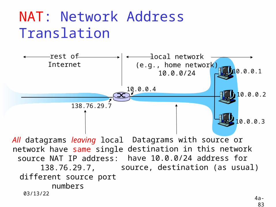
NAT: Network Address Translation
10.0.0.1
10.0.0.2
10.0.0.3
10.0.0.4
138.76.29.7
local network(e.g., home network)
10.0.0/24
rest ofInternet
Datagrams with source or destination in this networkhave 10.0.0/24 address for
source, destination (as usual)
All datagrams leaving localnetwork have same single source
NAT IP address: 138.76.29.7,different source port numbers
04/18/234a-84
NAT: Network Address Translation
Motivation: local network uses just one IP address as far as outside word is concerned: no need to be allocated range of addresses from
ISP: - just one IP address is used for all devices can change addresses of devices in local network
without notifying outside world can change ISP without changing addresses of
devices in local network devices inside local net not explicitly
addressable, visible by outside world (a security plus).
04/18/234a-85
NAT: Network Address TranslationImplementation: NAT router must:
outgoing datagrams: replace (source IP address, port #) of every outgoing datagram to (NAT IP address, new port #)
. . . remote clients/servers will respond using (NAT IP address, new port #) as destination addr.
remember (in NAT translation table) every (source IP address, port #) to (NAT IP address, new port #) translation pair
incoming datagrams: replace (NAT IP address, new port #) in dest fields of every incoming datagram with corresponding (source IP address, port #) stored in NAT table
04/18/234a-86
NAT: Network Address Translation
10.0.0.1
10.0.0.2
10.0.0.3
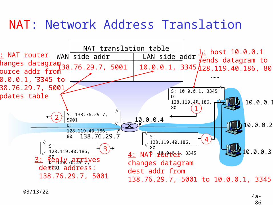
S: 10.0.0.1, 3345D: 128.119.40.186, 80
1
10.0.0.4
138.76.29.7
1: host 10.0.0.1 sends datagram to 128.119.40.186, 80
NAT translation tableWAN side addr LAN side addr
138.76.29.7, 5001 10.0.0.1, 3345…… ……
S: 128.119.40.186, 80 D: 10.0.0.1, 3345
4
S: 138.76.29.7, 5001D: 128.119.40.186, 80
2
2: NAT routerchanges datagramsource addr from10.0.0.1, 3345 to138.76.29.7, 5001,updates table
S: 128.119.40.186, 80 D: 138.76.29.7, 5001
3
3: Reply arrives dest. address: 138.76.29.7, 5001
4: NAT routerchanges datagramdest addr from138.76.29.7, 5001 to 10.0.0.1, 3345

04/18/234a-87
NAT: Network Address Translation
16-bit port-number field: 60,000 simultaneous connections with a
single LAN-side address! NAT is controversial:
routers should only process up to layer 3 violates end-to-end argument
• NAT possibility must be taken into account by app designers, e.g., P2P applications
address shortage should instead be solved by IPv6
04/18/234a-88
IPv6 Initial motivation: 32-bit address space will
be completely allocated by 2008 Additional motivation:
streamline the IP protocol to reduce processing overhead
04/18/234a-89
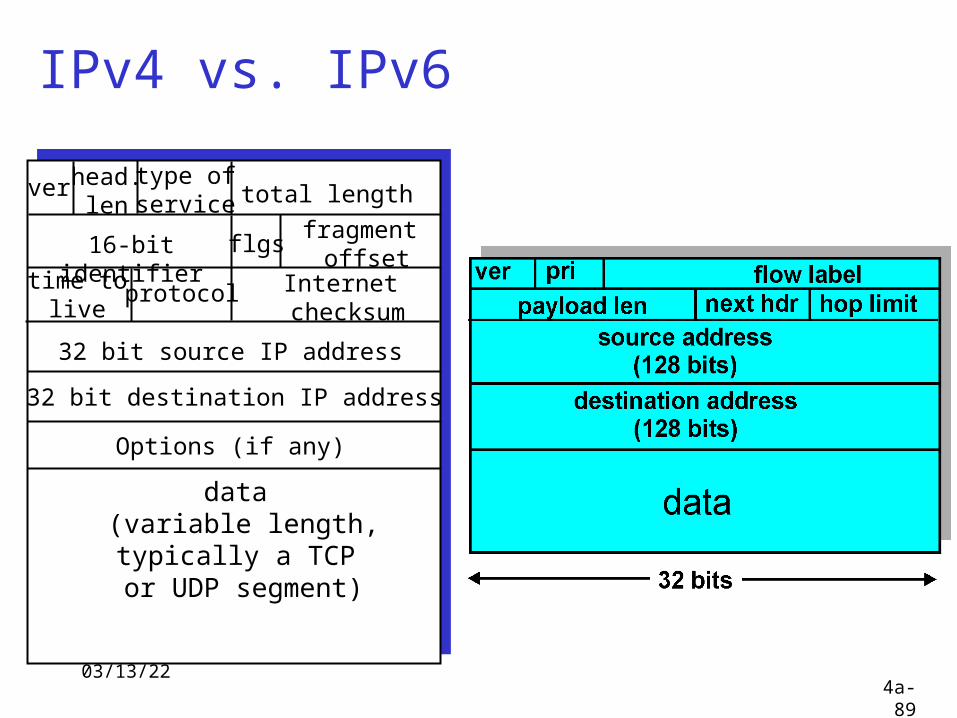
ver total length
data (variable length,typically a TCP
or UDP segment)
16-bit identifier
Internet checksum
time tolive
32 bit source IP address
head.len
type ofservice
flgsfragment
offsetprotocol
32 bit destination IP address
Options (if any)
IPv4 vs. IPv6
04/18/234a-90
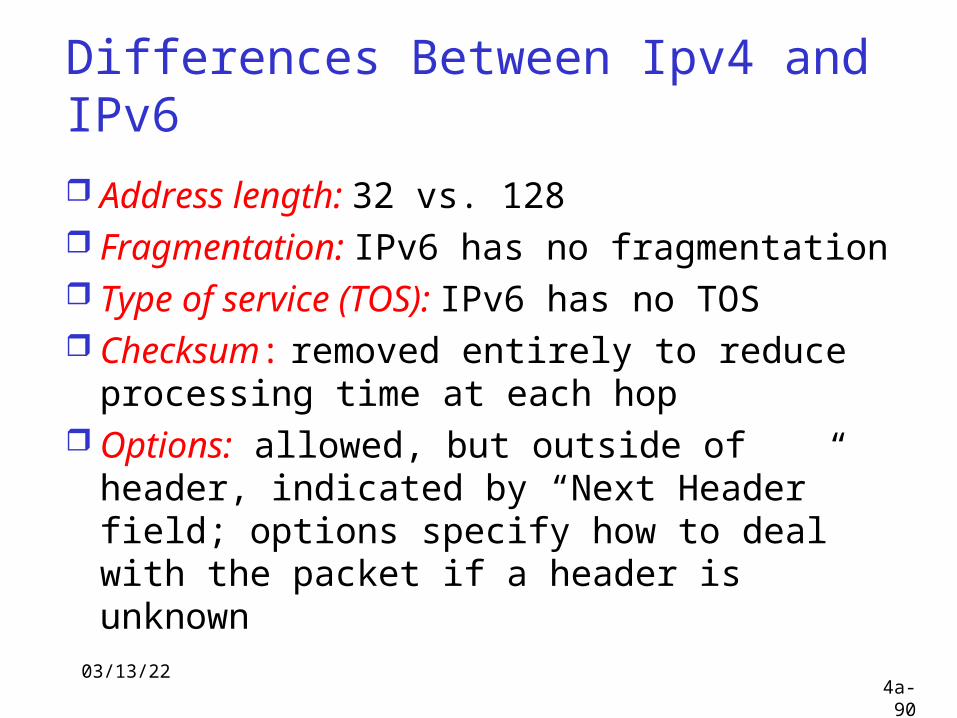
Differences Between Ipv4 and IPv6
Address length: 32 vs. 128 Fragmentation: IPv6 has no
fragmentation Type of service (TOS): IPv6 has no TOS Checksum: removed entirely to reduce
processing time at each hop Options: allowed, but outside of header,
indicated by “Next Header” field; options specify how to deal with the packet if a header is unknown
04/18/234a-91
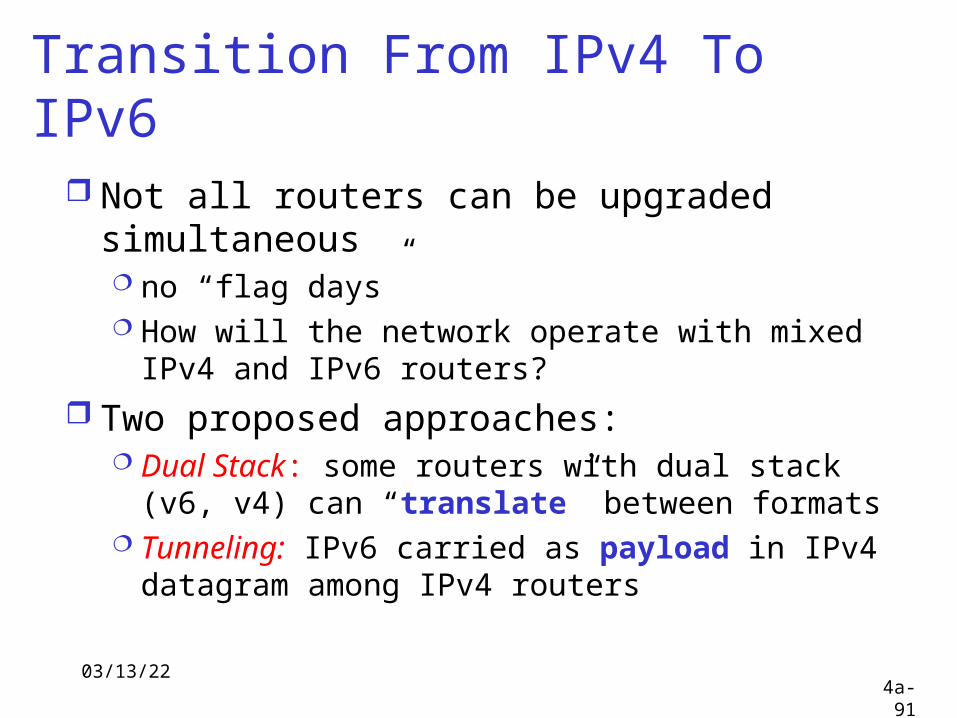
Transition From IPv4 To IPv6
Not all routers can be upgraded simultaneous no “flag days” How will the network operate with mixed IPv4
and IPv6 routers? Two proposed approaches:
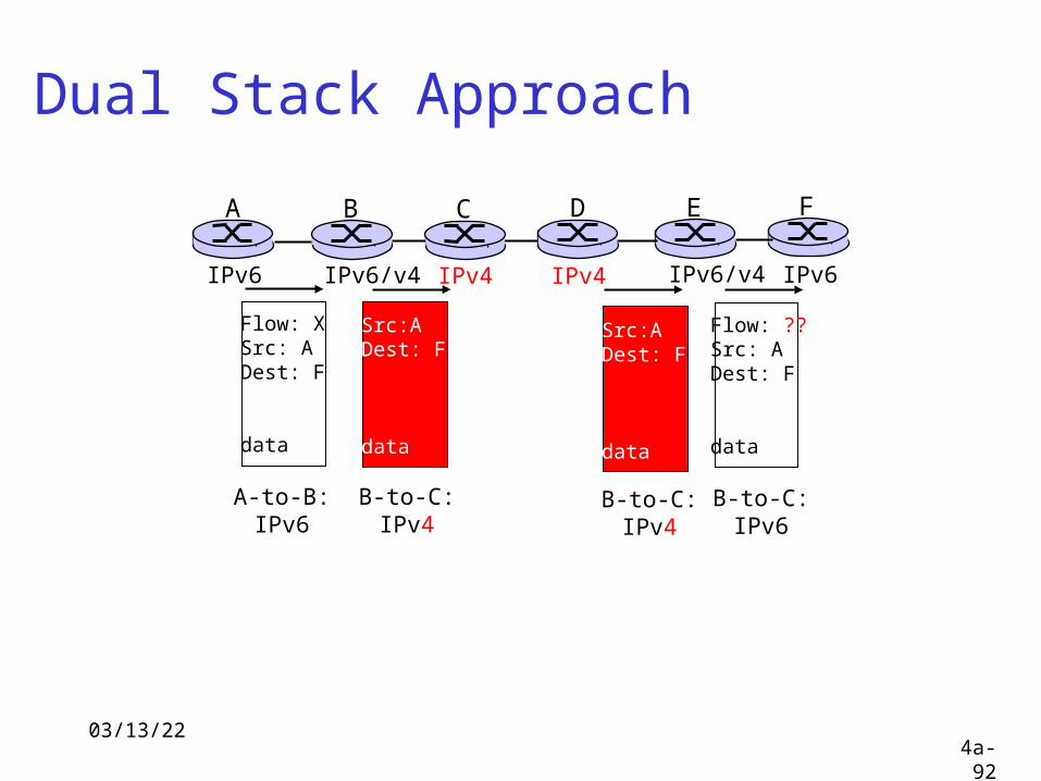
Dual Stack: some routers with dual stack (v6, v4) can “translate” between formats
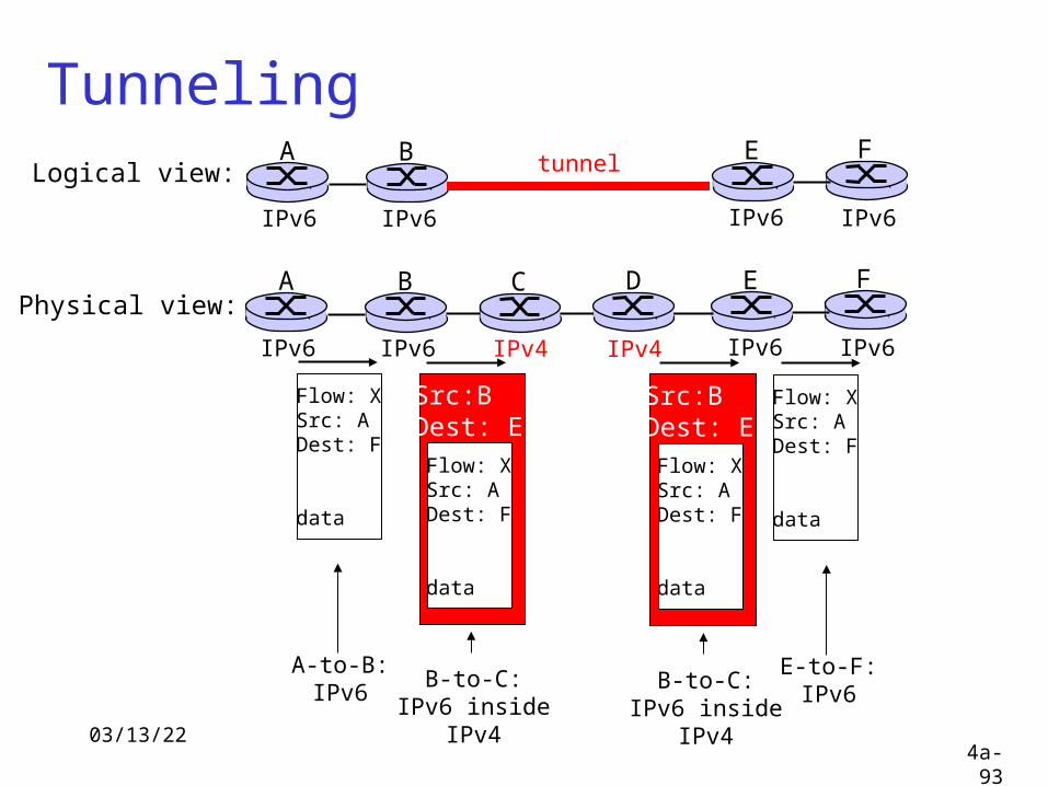
Tunneling: IPv6 carried as payload in IPv4 datagram among IPv4 routers
04/18/234a-92
Dual Stack Approach
A B E F
IPv6 IPv6/v4 IPv6/v4 IPv6
C D
IPv4 IPv4
Flow: XSrc: ADest: F
data
Flow: ??Src: ADest: F
data
Src:ADest: F
data
A-to-B:IPv6
Src:ADest: F
data
B-to-C:IPv4
B-to-C:IPv4
B-to-C:IPv6
04/18/234a-93
TunnelingA B E F
IPv6 IPv6 IPv6 IPv6
tunnelLogical view:
Physical view:A B E F
IPv6 IPv6 IPv6 IPv6
C D
IPv4 IPv4
Flow: XSrc: ADest: F
data
Flow: XSrc: ADest: F
data
Flow: XSrc: ADest: F
data
Src:BDest: E
Flow: XSrc: ADest: F
data
Src:BDest: E
A-to-B:IPv6
E-to-F:IPv6
B-to-C:IPv6 inside
IPv4
B-to-C:IPv6 inside
IPv4
04/18/234a-94
Network Layer: summaryWhat we’ve covered: network layer services routing principles: link
state and distance vector hierarchical routing IP Internet routing protocols
reliable transfer intra-domain: RIP, OSPF inter-domain: BGP
IPv6