Embed Size (px)
Citation preview
1
Avoid mounting components orrouting wires near hot surfaces
Avoid mounting components orrouting wires near moving parts
Tape or loom wires under hoodfor protection and appearance
Use grommets when routing wiresthrough metal surfaces
Use a voltmeter for testing andverifying circuits
Installation Precautions:
Roll down window to avoid lockingkeys in vehicle during installation
FCC COMPLIANCE
This device complies with Part 15 of the FCC rules and with RSS-210 of Industry Canada. Operation is subject to the following two conditions:
1. This device may not cause harmful interference, and
2. This device must accept any interference received, including any interference that may cause undesired operation.
Warning!
Changes or modifications not expressly approved by the party responsible for compliance could void the user’s authority to operate the equipment.
CSI-400 Installation Instructions
Kit Contents
(1) - CSI-400 Control Module
(2) - 4 Button High Frequency Transmitters
(1) - 3 Channel Code Learning Receiver(1) - Multi Pin Input/Output Harness
(1) - Six Pin Harness
(1) - 2 Pin Door Lock Harness(2) - 30 Amp In-line Fuse Holders With Fuses
(1) - Control Switch
(1) - Programming Switch
(1) - Ring Terminal(4) - 1/2" Long Screws
(1) - Hood Pin Switch
(1) - Remote Start Warning Label(1) - Literature Package
(1) - Installation CD-ROM
Note: Do not install this system on a vehiclethat is not equipped with the following:
• Automatic Transmission• Fuel Injection• Ignition / Shift Interlock
Technical Support (800) 421-3209
2
BEFORE INSTALLING THIS SYSTEM
Required Tools1. Digital Voltmeter or Multimeter
2. Wire Strippers
3. Wire Crimpers4. Wire Cutters
5. Electric Drill with Drill Bits
6. Various Screwdrivers7. Mechanics Socket Set
8. Electrical Tape
9. Tie Straps
WARNING!!Use of a grounding type test light or logic probe could cause damage to vehicle electronics. It is
strongly recomended that a digital voltmeter/multimeter be used to test vehicle circuits.
Vehicle Information
1. Obtain a printout of a wire and location chart for the vehicle from the internet.
http://techservices.codesystems.comUsername: DIY
Password: 852
2. Check with your authorized Code Alarm dealer for any additional parts or accessories necessary tocomplete the installation (i.e. door lock interface or relays).
3. If you have additional questions or need installation support the Code Alarm Technical Services team canbe reached at (800)421-3209.
Plan your Installation
1. Allocate 4-5 hours for a typical installation.
2. Choose a well ventilated area to work.3. Read through the entire installation manual prior to starting the installation.
4. Locate and verify all vehicle wiring prior to making connections.
5. Locate mounting locations for components (control module, LED, programming switch etc.).6. Prep the wiring harness (group wires that will be going to the same area in the vehicle)
7. Cut wires to fit before making connections in the vehicle. This will make for a neater installation.
Code Alarm is not responsible for damage to people or property caused by installation or use of this product.
Code Alarm recommends installation by qualified personnel
3
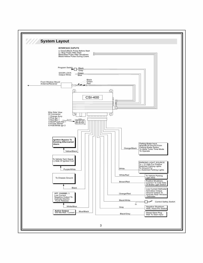
System Layout
Ignition Bypass ToExisting AftermarketAlarm
Active Output
OPT. CHANNEL 1
INTERFACE OUPUTS
4
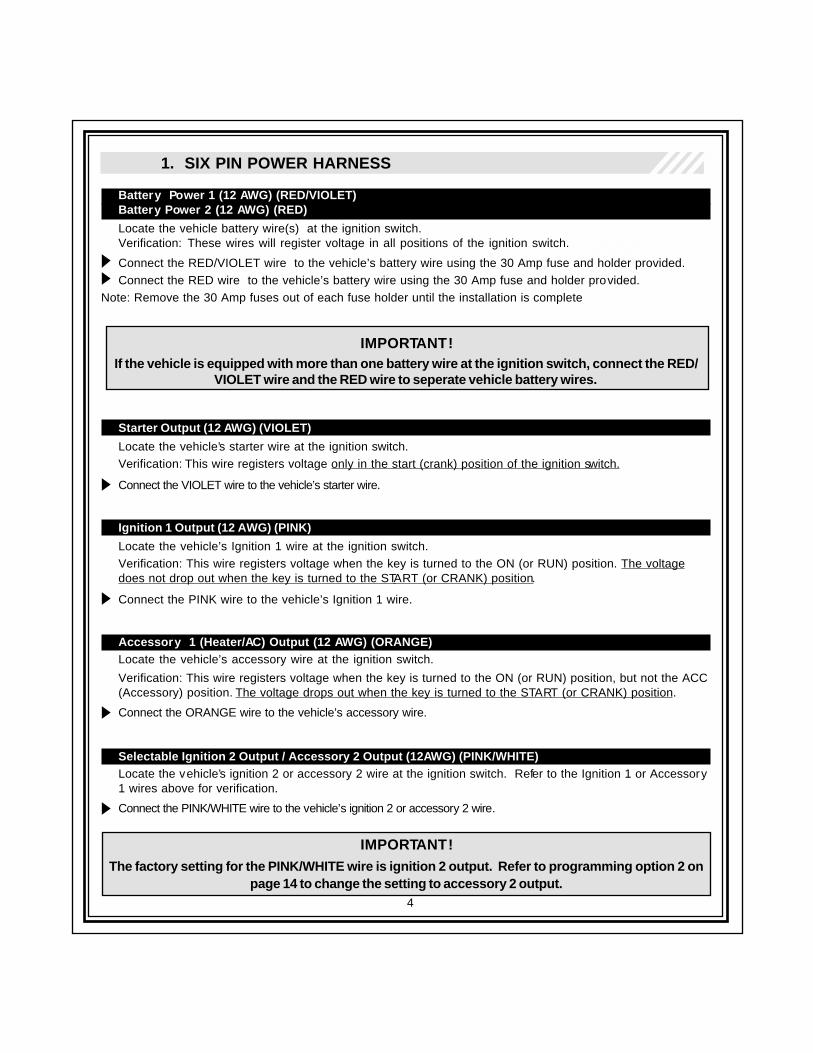
1. SIX PIN POWER HARNESS
Battery Power 1 (12 AWG) (RED/VIOLET)Battery Power 2 (12 AWG) (RED)
Locate the vehicle battery wire(s) at the ignition switch.Verification: These wires will register voltage in all positions of the ignition switch.
Connect the RED/VIOLET wire to the vehicle’s battery wire using the 30 Amp fuse and holder provided.Connect the RED wire to the vehicle’s battery wire using the 30 Amp fuse and holder provided.
Note: Remove the 30 Amp fuses out of each fuse holder until the installation is complete
IMPORTANT!If the vehicle is equipped with more than one battery wire at the ignition switch, connect the RED/
VIOLET wire and the RED wire to seperate vehicle battery wires.
Starter Output (12 AWG) (VIOLET)
Locate the vehicle’s starter wire at the ignition switch.Verification: This wire registers voltage only in the start (crank) position of the ignition switch.
Connect the VIOLET wire to the vehicle’s starter wire.
Ignition 1 Output (12 AWG) (PINK)
Locate the vehicle’s Ignition 1 wire at the ignition switch.Verification: This wire registers voltage when the key is turned to the ON (or RUN) position. The voltagedoes not drop out when the key is turned to the START (or CRANK) position.
Connect the PINK wire to the vehicle’s Ignition 1 wire.
Accessory 1 (Heater/AC) Output (12 AWG) (ORANGE)Locate the vehicle’s accessory wire at the ignition switch.
Verification: This wire registers voltage when the key is turned to the ON (or RUN) position, but not the ACC(Accessory) position. The voltage drops out when the key is turned to the START (or CRANK) position.
Connect the ORANGE wire to the vehicle’s accessory wire.
Selectable Ignition 2 Output / Accessory 2 Output (12AWG) (PINK/WHITE)Locate the vehicle’s ignition 2 or accessory 2 wire at the ignition switch. Refer to the Ignition 1 or Accessory1 wires above for verification.
Connect the PINK/WHITE wire to the vehicle’s ignition 2 or accessory 2 wire.
IMPORTANT!The factory setting for the PINK/WHITE wire is ignition 2 output. Refer to programming option 2 on
page 14 to change the setting to accessory 2 output.
5
2. TWELVE PIN INPUT / OUTPUT HARNESS
Chassis Ground Source (18 AWG) (BLACK)
Connect the BLACK wire to a solid chassis ground point using the supplied ring terminal and 1/2” longscrew. Scrape away paint from the grounding point to ensure a good connection. The recommendedgrounding point is a painted metal surface in the driver’s side kick panel area.
Note: Do not ground the BLACK wire with any other vehicle components.
Control Safety Switch (18 AWG) (BLACK/WHITE)Control Safety Switch Mounting
Connect the BLACK/WHITE wire to one wire of the supplied control safety switch (ON/OFF toggle switch).
Connect the other wire of the supplied control safety switch to a chassis ground source.
Mount the control safety switch in a location easily accessible by the driver. Drill a 1/4” hole verifying clearance behindthe chosen mounting location and secure the control safety switch with the star washer and nut.
Hood Pin Switch MountingNegative Shutdown Wire (18 AWG) (GRAY)
Mount the supplied hood pin switch in an area allowing the hood to depress the switch at least 1/4” whenclosed. Use care to make sure the hood pin switch is mounted away from water drain paths. If necessary,the included bracket may be used to mount the hood pin switch away from rain gutters or for mountingagainst the fire wall. Carefully check behind the chosen location for fluid lines or electrical wiring. Thehood pin switch must be mounted into a metal chassis ground surface.
For direct mounting, drill a 1/4” hole and thread the hood pin switch into the hole and tighten with a 7/16”nutdriver.
Route the GRAY wire through an existing grommet (if available) in the firewall and connect to the mountedhood pin switch.
IMPORTANT!The hood pin switch will prevent the vehicle from remote starting if the vehicle’s hood is open.
Failure to install the hood pin switch may result in personal injury or property damage.
Positive Shutdown, Brake Safety Switch Wire (18 AWG) (BROWN/RED)
Locate the vehicle’s brake light wire at the brake pedal mounted switch.Verification: This wire registers positive voltage when the brake pedal is pressed.
Connect the BROWN/RED wire to the vehicle’s brake light wire.
6
2. TWELVE PIN INPUT / OUTPUT HARNESS, CONTINUED
Parking Light Polarity Feed (18AWG) (WHITE/RED)Parking Light Output (18 AWG) (WHITE)
Positive Switching Parking Lights:
Locate the parking light output wire at the vehicle’s light switch.
Verification: This wire registers positive voltage when the parking lights are turned on.
Connect the WHITE/RED wire to a 15 Amp max fused battery source.
Connect the WHITE wire to the parking light output wire at the vehicle’s light switch.
Negative Switching Parking Lights:
Locate the parking light output wire at the vehicle’s light switch.Verification: This wire registers ground when the parking lights are turned on.
Connect the WHITE/RED wire to a good chassis ground.
Connect the WHITE wire to the parking light output wire at the vehicle’s light switch.
Ignition Bypass To Existing Factory Alarm (18 AWG) (YELLOW/BLACK)
NOTE!This wire is only required when the remote start system is used in conjunction with an additional
remote activated aftermarket security system.
Locate the ignition input wire at the control module of the aftermarket security system.
Verification: This wire receives voltage when the ignition key is in the ON (or RUN) position. The voltagedoes not drop out when the key is turned to the START (or CRANK) position.
Disconnect the aftermarket alarm’s ignition input wire from its source.
Connect the YELLOW/BLACK wire to the aftermarket alarm’s previously disconnected ignition input wire.
Vehicle Tach Signal (18 AWG) (VIOLET/WHITE)
Locate the vehicle’s ignition coil or fuel injector in the engine compartment.
Verification: Refer to Vehicle Wire Color and Location Chart for the wire color and location, or test usingthe following procedure:1. Set voltmeter to AC VOLTS.2. Attach positive lead of a volt meter to a constant 12-volt source.3. Attach negative lead of a volt meter to the wire to be tested.4. Start the engine.5. Have someone press on the gas pedal slightly as you monitor the meter. If connected to the correct
wire, the voltage reading will increase as the engine’s RPM increases.
Connect the VIOLET/WHITE wire to the negative side of the vehicle ignition coil or fuel injector.
7
2. TWELVE PIN INPUT / OUTPUT HARNESS, CONTINUED
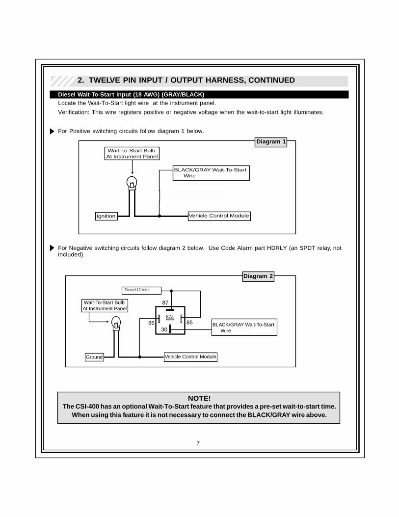
Diesel Wait-To-Start Input (18 AWG) (GRAY/BLACK)Locate the Wait-To-Start light wire at the instrument panel.
Verification: This wire registers positive or negative voltage when the wait-to-start light illuminates.
For Positive switching circuits follow diagram 1 below.
For Negative switching circuits follow diagram 2 below. Use Code Alarm part HDRLY (an SPDT relay, notincluded).
NOTE!The CSI-400 has an optional Wait-To-Start feature that provides a pre-set wait-to-start time.
When using this feature it is not necessary to connect the BLACK/GRAY wire above.
30
87
87a
86 85 BLACK/GRAY Wait-To-Start Wire
Vehicle Control ModuleGround
Chassis Ground
Wait-To-Start Bulb At Instrument Panel
BLACK/GRAY Wait-To-Start Wire
Vehicle Control ModuleIgnition
Wait-To-Start Bulb At Instrument Panel
1N4004 Diode
Diagram 1
Diagram 2
Fused 12 Volts
8
2. TWELVE PIN INPUT / OUTPUT HARNESS, CONTINUED
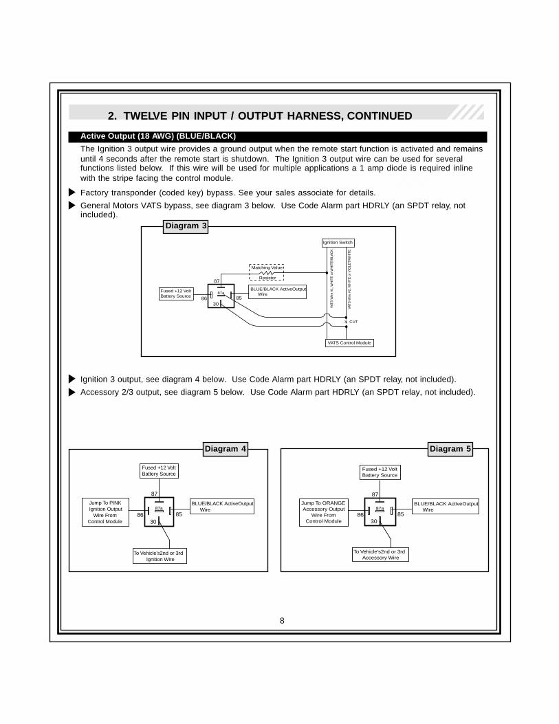
Active Output (18 AWG) (BLUE/BLACK)
The Ignition 3 output wire provides a ground output when the remote start function is activated and remainsuntil 4 seconds after the remote start is shutdown. The Ignition 3 output wire can be used for severalfunctions listed below. If this wire will be used for multiple applications a 1 amp diode is required inlinewith the stripe facing the control module.
Factory transponder (coded key) bypass. See your sales associate for details.
General Motors VATS bypass, see diagram 3 below. Use Code Alarm part HDRLY (an SPDT relay, notincluded).
Ignition 3 output, see diagram 4 below. Use Code Alarm part HDRLY (an SPDT relay, not included).
Accessory 2/3 output, see diagram 5 below. Use Code Alarm part HDRLY (an SPDT relay, not included).
Diagram 3
Diagram 5
Fused +12 VoltBattery Source
30
87
87a
86 85
BLUE/BLACK ActiveOutput Wire
VATS Control Module
Matching Value
Resistor
Ignition Switch
VATS
Wire
#1,
WH
ITE
or W
HIT
E/B
LAC
K
VATS
Wire
#2,
WH
ITE
or V
IOLE
T/W
HIT
E
X CUT
Diagram 4
Fused +12 VoltBattery Source
30
87
87a
86 85
BLUE/BLACK ActiveOutput Wire
To Vehicle's2nd or 3rd Ignition Wire
Jump To PINK Ignition Output Wire From Control Module
Fused +12 VoltBattery Source
30
87
87a
86 85
BLUE/BLACK ActiveOutput Wire
To Vehicle's2nd or 3rd Accessory Wire
Jump To ORANGE Accessory Output Wire From Control Module
9
2. TWELVE PIN INPUT / OUTPUT HARNESS, CONTINUED
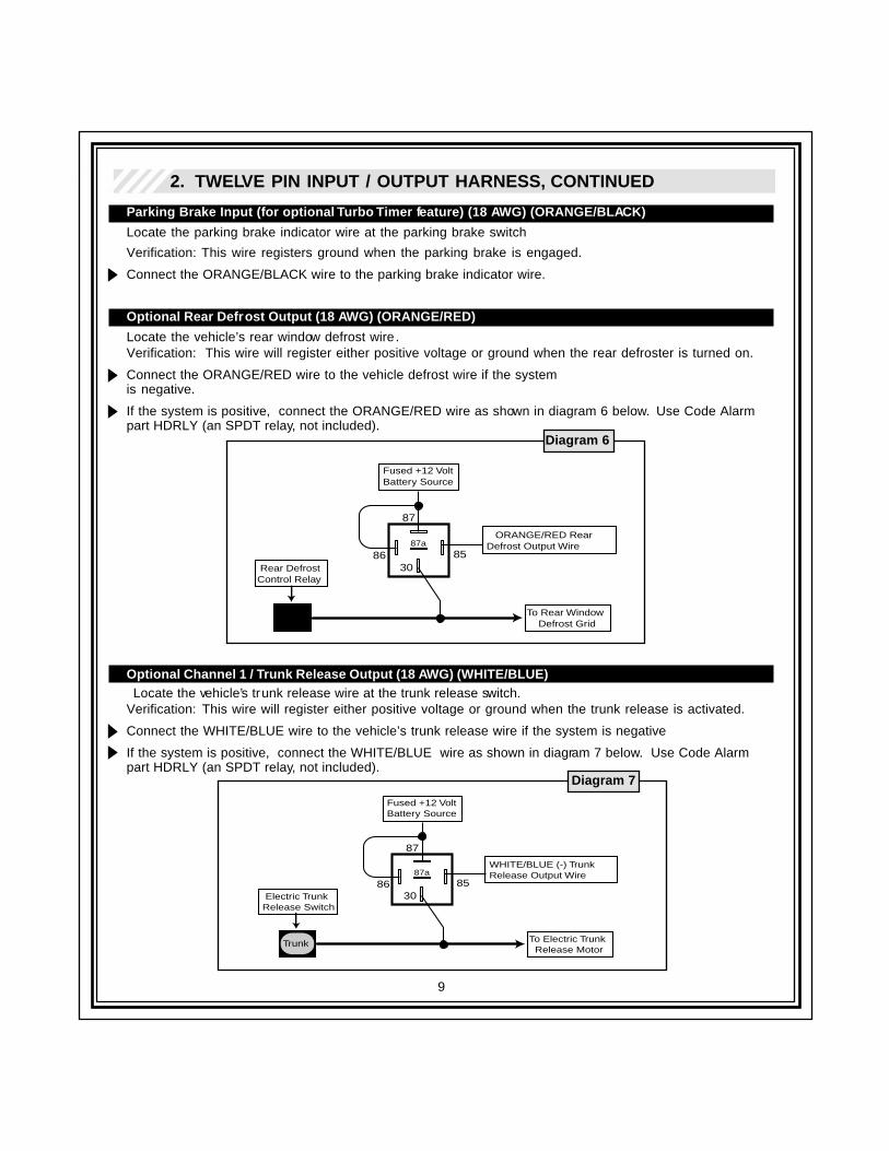
Parking Brake Input (for optional Turbo Timer feature) (18 AWG) (ORANGE/BLACK)
Locate the parking brake indicator wire at the parking brake switch
Verification: This wire registers ground when the parking brake is engaged.
Connect the ORANGE/BLACK wire to the parking brake indicator wire.
Optional Rear Defrost Output (18 AWG) (ORANGE/RED)
Locate the vehicle’s rear window defrost wire .Verification: This wire will register either positive voltage or ground when the rear defroster is turned on.
Connect the ORANGE/RED wire to the vehicle defrost wire if the systemis negative.
If the system is positive, connect the ORANGE/RED wire as shown in diagram 6 below. Use Code Alarmpart HDRLY (an SPDT relay, not included).
Optional Channel 1 / Trunk Release Output (18 AWG) (WHITE/BLUE) Locate the vehicle’s trunk release wire at the trunk release switch.
Verification: This wire will register either positive voltage or ground when the trunk release is activated.
Connect the WHITE/BLUE wire to the vehicle’s trunk release wire if the system is negative
If the system is positive, connect the WHITE/BLUE wire as shown in diagram 7 below. Use Code Alarmpart HDRLY (an SPDT relay, not included).
Diagram 6
Fused +12 VoltBattery Source
30
87
87a
86 85
ORANGE/RED Rear Defrost Output Wire
To Rear Window Defrost Grid
Rear DefrostControl Relay
Fused +12 VoltBattery Source
30
87
87a
86 85
WHITE/BLUE (-) Trunk Release Output Wire
To Electric Trunk Release Motor
Electric TrunkRelease Switch
Trunk
Diagram 7
10
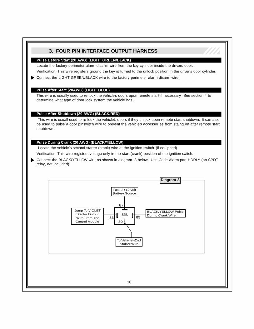
3. FOUR PIN INTERFACE OUTPUT HARNESS
Pulse Before Start (20 AWG) (LIGHT GREEN/BLACK)Locate the factory perimeter alarm disarm wire from the key cylinder inside the drivers door.
Verification: This wire registers ground the key is turned to the unlock position in the driver’s door cylinder.
Connect the LIGHT GREEN/BLACK wire to the factory perimeter alarm disarm wire.
Pulse After Start (20AWG) (LIGHT BLUE)This wire is usually used to re-lock the vehicle’s doors upon remote star t if necessary. See section 4 todetermine what type of door lock system the vehicle has.
Pulse After Shutdown (20 AWG) (BLACK/RED)
This wire is usuall used to re-lock the vehicle’s doors if they unlock upon remote start shutdown. It can alsobe used to pulse a door pinswitch wire to prevent the vehicle’s accessor ies from staing on after remote startshutdown.
Pulse During Crank (20 AWG) (BLACK/YELLOW) Locate the vehicle’s second starter (crank) wire at the ignition switch. (if equipped)
Verification: This wire registers voltage only in the start (crank) position of the ignition switch.
Connect the BLACK/YELLOW wire as shown in diagram 8 below. Use Code Alarm part HDRLY (an SPDTrelay, not included).
Diagram 8
Fused +12 VoltBattery Source
30
87
87a
86 85
BLACK/YELLOW PulseDuring Crank Wire
To Vehicle's2nd Starter Wire
Jump To VIOLET Starter Output Wire From The Control Module
11
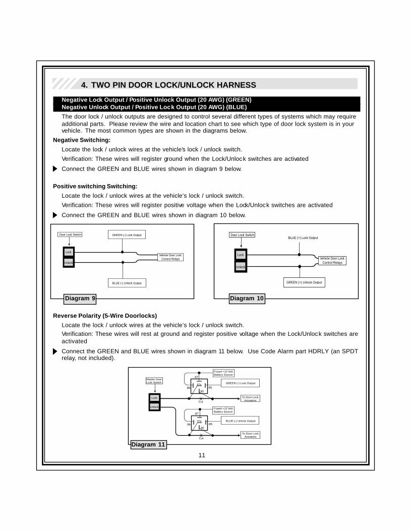
4. TWO PIN DOOR LOCK/UNLOCK HARNESS
Negative Lock Output / Positive Unlock Output (20 AWG) (GREEN)Negative Unlock Output / Positive Lock Output (20 AWG) (BLUE)
The door lock / unlock outputs are designed to control several different types of systems which may requireadditional parts. Please review the wire and location chart to see which type of door lock system is in yourvehicle. The most common types are shown in the diagrams below.
Negative Switching:
Locate the lock / unlock wires at the vehicle’s lock / unlock switch.
Verification: These wires will register ground when the Lock/Unlock switches are activated
Connect the GREEN and BLUE wires shown in diagram 9 below.
Positive switching Switching:
Locate the lock / unlock wires at the vehicle’s lock / unlock switch.
Verification: These wires will register positive voltage when the Lock/Unlock switches are activated
Connect the GREEN and BLUE wires shown in diagram 10 below.
Reverse Polarity (5-Wire Doorlocks)
Locate the lock / unlock wires at the vehicle’s lock / unlock switch.Verification: These wires will rest at ground and register positive voltage when the Lock/Unlock switches areactivated
Connect the GREEN and BLUE wires shown in diagram 11 below. Use Code Alarm part HDRLY (an SPDTrelay, not included).
Diagram 9 Diagram 10
Lock
Unlock
Door Lock Switch
Vehicle Door Lock Control Relays
GREEN (-) Lock Output
BLUE (-) Unlock Output
Lock
Unlock
Door Lock Switch
Vehicle Door Lock Control Relays
BLUE (+) Lock Output
GREEN (+) Unlock Output
30
87
87a
86 85
Cut
Fused +12 VoltBattery Source
Lock
Unlock
Master Door Lock Switch
X
30
87
87a
86 85
XTo Door Lock Actuators
To Door Lock Actuators
GREEN (-) Lock Output
BLUE (-) Unlock Output
Fused +12 VoltBattery Source
Cut
Diagram 11
12
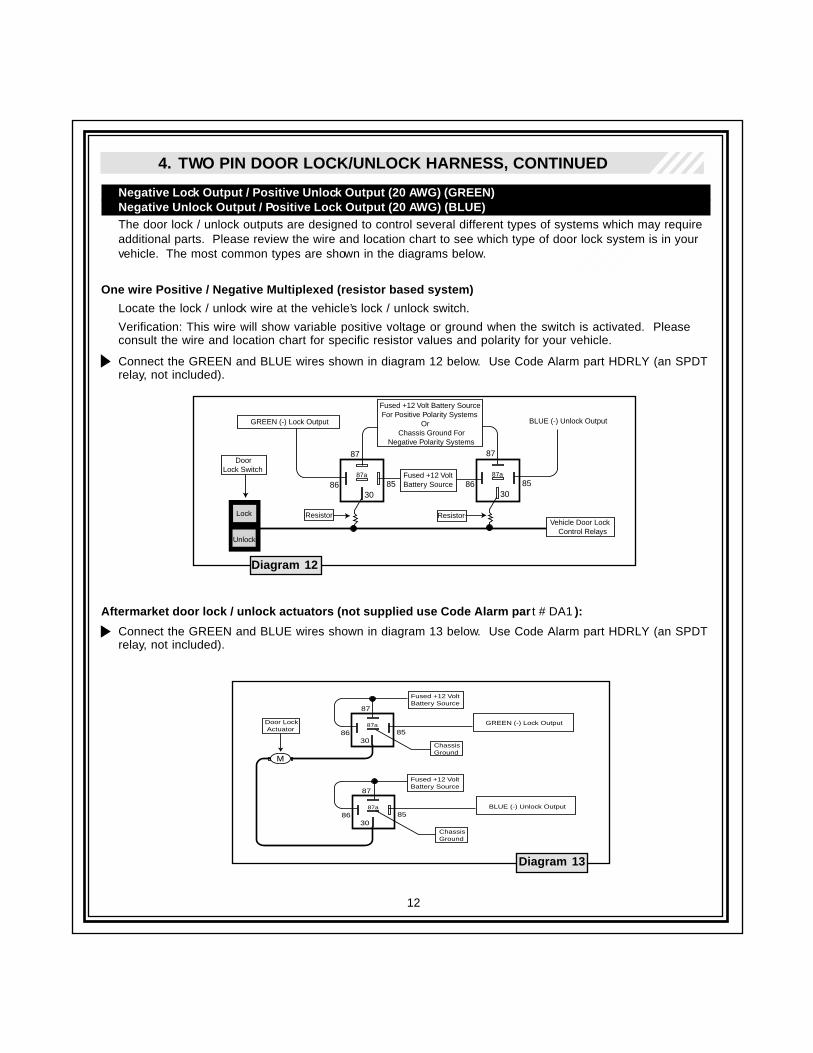
4. TWO PIN DOOR LOCK/UNLOCK HARNESS, CONTINUED
Negative Lock Output / Positive Unlock Output (20 AWG) (GREEN)Negative Unlock Output / Positive Lock Output (20 AWG) (BLUE)The door lock / unlock outputs are designed to control several different types of systems which may requireadditional parts. Please review the wire and location chart to see which type of door lock system is in yourvehicle. The most common types are shown in the diagrams below.
One wire Positive / Negative Multiplexed (resistor based system)
Locate the lock / unlock wire at the vehicle’s lock / unlock switch.
Verification: This wire will show variable positive voltage or ground when the switch is activated. Pleaseconsult the wire and location chart for specific resistor values and polarity for your vehicle.
Connect the GREEN and BLUE wires shown in diagram 12 below. Use Code Alarm part HDRLY (an SPDTrelay, not included).
Aftermarket door lock / unlock actuators (not supplied use Code Alarm par t # DA1 ):
Connect the GREEN and BLUE wires shown in diagram 13 below. Use Code Alarm part HDRLY (an SPDTrelay, not included).
Diagram 12
Diagram 13
30
87
87a
86 85Fused +12 VoltBattery Source
Lock
Unlock
Door Lock Switch
30
87
87a
86 85
GREEN (-) Lock Output BLUE (-) Unlock Output
Fused +12 Volt Battery Source For Positive Polarity Systems Or Chassis Ground For Negative Polarity Systems
Resistor ResistorVehicle Door Lock Control Relays
30
87
87a
86 85
Fused +12 VoltBattery Source
Door Lock Actuator
30
87
87a
86 85
ChassisGround
ChassisGround
GREEN (-) Lock Output
BLUE (-) Unlock Output
Fused +12 VoltBattery Source
M
13
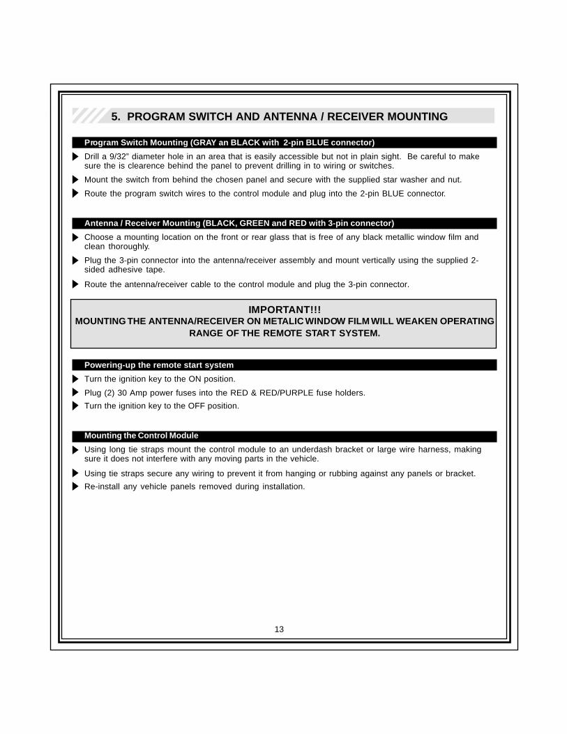
5. PROGRAM SWITCH AND ANTENNA / RECEIVER MOUNTING
Program Switch Mounting (GRAY an BLACK with 2-pin BLUE connector)
Drill a 9/32” diameter hole in an area that is easily accessible but not in plain sight. Be careful to makesure the is clearence behind the panel to prevent drilling in to wiring or switches.
Mount the switch from behind the chosen panel and secure with the supplied star washer and nut.
Route the program switch wires to the control module and plug into the 2-pin BLUE connector.
Antenna / Receiver Mounting (BLACK, GREEN and RED with 3-pin connector)
Choose a mounting location on the front or rear glass that is free of any black metallic window film andclean thoroughly.
Plug the 3-pin connector into the antenna/receiver assembly and mount vertically using the supplied 2-sided adhesive tape.
Route the antenna/receiver cable to the control module and plug the 3-pin connector.
IMPORTANT!!!MOUNTING THE ANTENNA/RECEIVER ON METALIC WINDOW FILM WILL WEAKEN OPERATING
RANGE OF THE REMOTE START SYSTEM.
Powering-up the remote start system
Turn the ignition key to the ON position.
Plug (2) 30 Amp power fuses into the RED & RED/PURPLE fuse holders.
Turn the ignition key to the OFF position.
Mounting the Control Module
Using long tie straps mount the control module to an underdash bracket or large wire harness, makingsure it does not interfere with any moving parts in the vehicle.
Using tie straps secure any wiring to prevent it from hanging or rubbing against any panels or bracket.
Re-install any vehicle panels removed during installation.
14
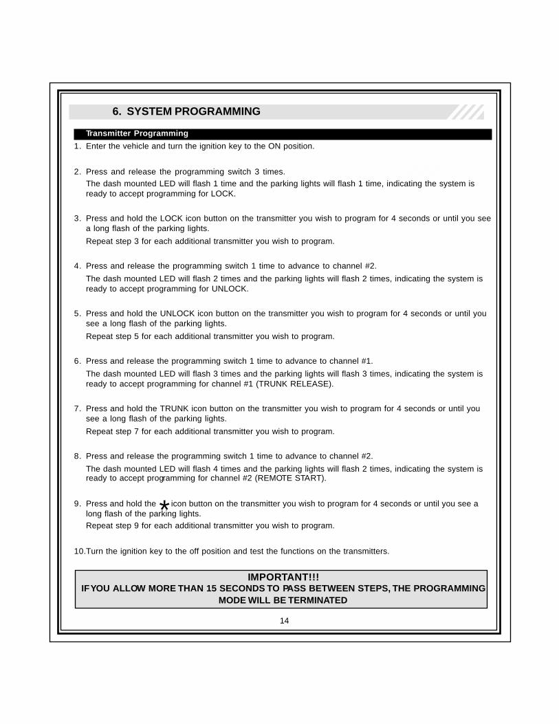
6. SYSTEM PROGRAMMING
Transmitter Programming
1. Enter the vehicle and turn the ignition key to the ON position.
2. Press and release the programming switch 3 times.The dash mounted LED will flash 1 time and the parking lights will flash 1 time, indicating the system isready to accept programming for LOCK.
3. Press and hold the LOCK icon button on the transmitter you wish to program for 4 seconds or until you seea long flash of the parking lights.
Repeat step 3 for each additional transmitter you wish to program.
4. Press and release the programming switch 1 time to advance to channel #2.
The dash mounted LED will flash 2 times and the parking lights will flash 2 times, indicating the system isready to accept programming for UNLOCK.
5. Press and hold the UNLOCK icon button on the transmitter you wish to program for 4 seconds or until yousee a long flash of the parking lights.
Repeat step 5 for each additional transmitter you wish to program.
6. Press and release the programming switch 1 time to advance to channel #1.
The dash mounted LED will flash 3 times and the parking lights will flash 3 times, indicating the system isready to accept programming for channel #1 (TRUNK RELEASE).
7. Press and hold the TRUNK icon button on the transmitter you wish to program for 4 seconds or until yousee a long flash of the parking lights.
Repeat step 7 for each additional transmitter you wish to program.
8. Press and release the programming switch 1 time to advance to channel #2.
The dash mounted LED will flash 4 times and the parking lights will flash 2 times, indicating the system isready to accept programming for channel #2 (REMOTE START).
9. Press and hold the icon button on the transmitter you wish to program for 4 seconds or until you see along flash of the parking lights.Repeat step 9 for each additional transmitter you wish to program.
10.Turn the ignition key to the off position and test the functions on the transmitters.
IMPORTANT!!!IF YOU ALLOW MORE THAN 15 SECONDS TO PASS BETWEEN STEPS, THE PROGRAMMING
MODE WILL BE TERMINATED
*
15
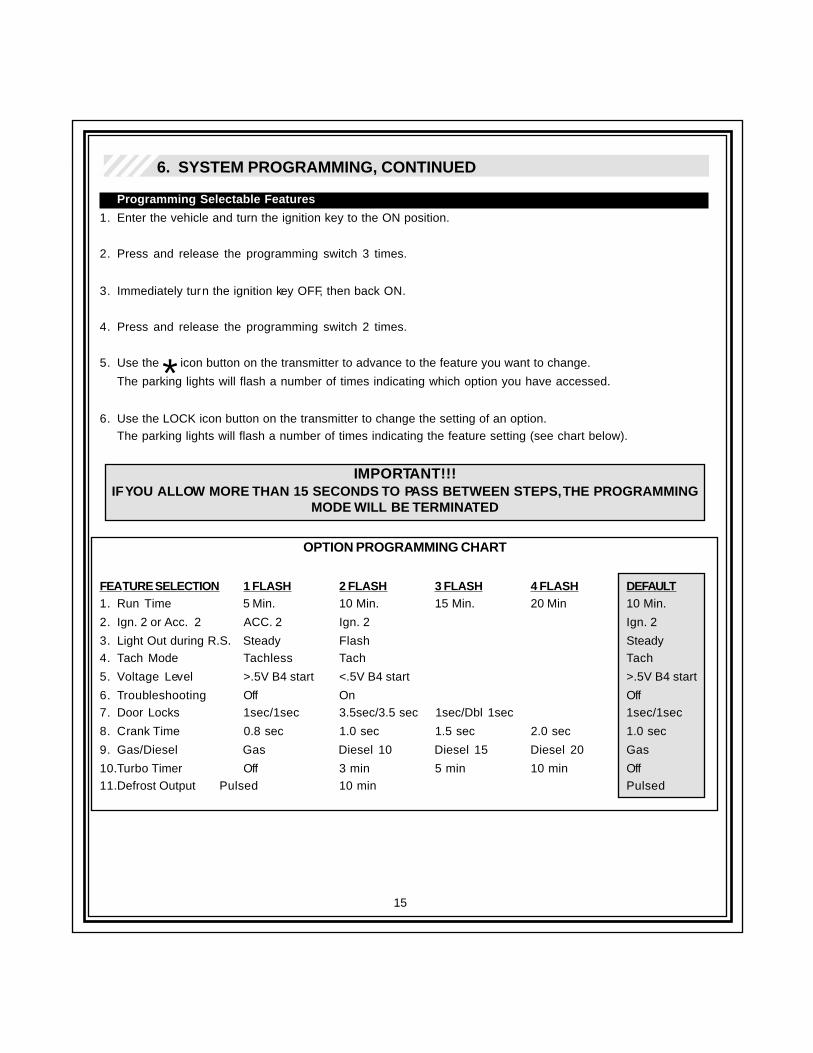
6. SYSTEM PROGRAMMING, CONTINUED
Programming Selectable Features
1. Enter the vehicle and turn the ignition key to the ON position.
2. Press and release the programming switch 3 times.
3. Immediately turn the ignition key OFF, then back ON.
4. Press and release the programming switch 2 times.
5. Use the icon button on the transmitter to advance to the feature you want to change.
The parking lights will flash a number of times indicating which option you have accessed.
6. Use the LOCK icon button on the transmitter to change the setting of an option.The parking lights will flash a number of times indicating the feature setting (see chart below).
IMPORTANT!!!IF YOU ALLOW MORE THAN 15 SECONDS TO PASS BETWEEN STEPS, THE PROGRAMMING
MODE WILL BE TERMINATED
OPTION PROGRAMMING CHART
FEATURE SELECTION 1 FLASH 2 FLASH 3 FLASH 4 FLASH DEFAULT1. Run Time 5 Min. 10 Min. 15 Min. 20 Min 10 Min.
2. Ign. 2 or Acc. 2 ACC. 2 Ign. 2 Ign. 2
3. Light Out during R.S. Steady Flash Steady4. Tach Mode Tachless Tach Tach
5. Voltage Level >.5V B4 start <.5V B4 start >.5V B4 start
6. Troubleshooting Off On Off7. Door Locks 1sec/1sec 3.5sec/3.5 sec 1sec/Dbl 1sec 1sec/1sec
8. Crank Time 0.8 sec 1.0 sec 1.5 sec 2.0 sec 1.0 sec
9. Gas/Diesel Gas Diesel 10 Diesel 15 Diesel 20 Gas
10.Turbo Timer Off 3 min 5 min 10 min Off11.Defrost Output Pulsed 10 min Pulsed
*
16
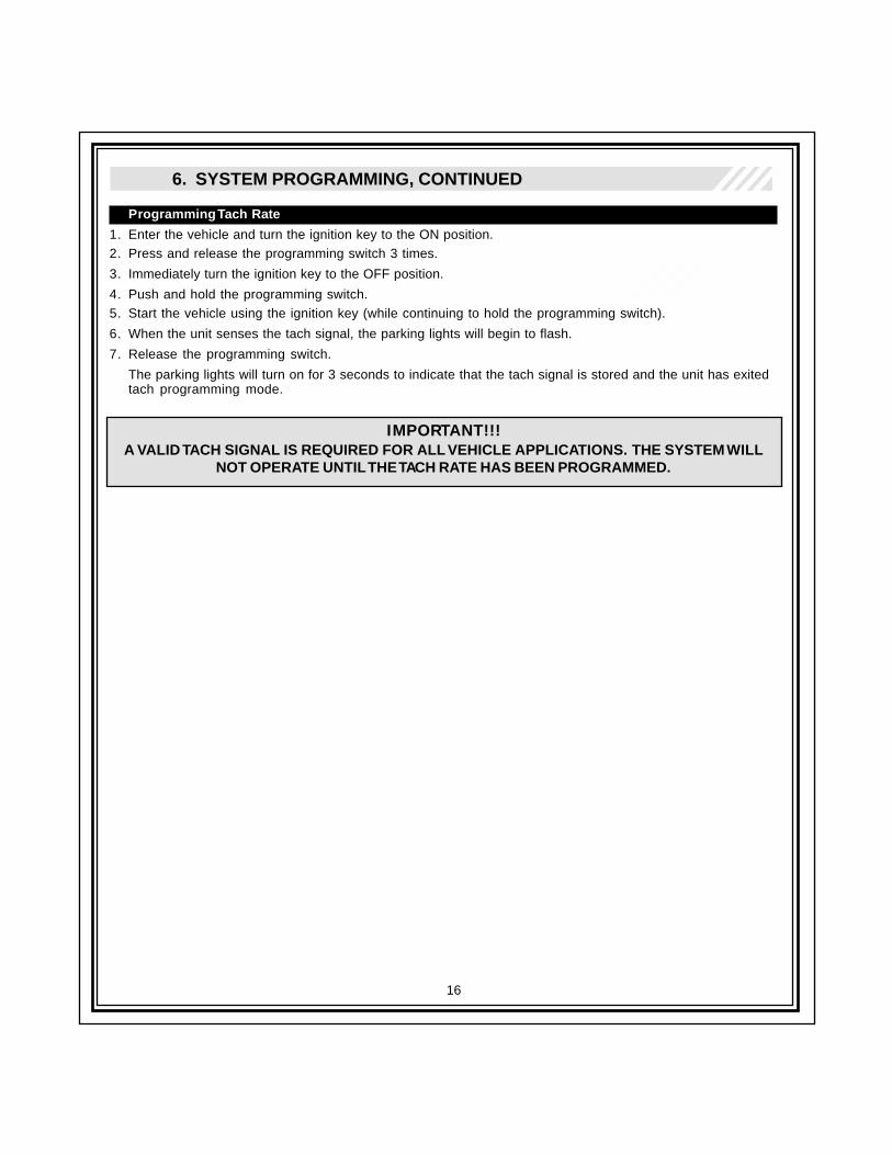
6. SYSTEM PROGRAMMING, CONTINUED
Programming Tach Rate
1. Enter the vehicle and turn the ignition key to the ON position.2. Press and release the programming switch 3 times.
3. Immediately turn the ignition key to the OFF position.
4. Push and hold the programming switch.5. Start the vehicle using the ignition key (while continuing to hold the programming switch).
6. When the unit senses the tach signal, the parking lights will begin to flash.
7. Release the programming switch.
The parking lights will turn on for 3 seconds to indicate that the tach signal is stored and the unit has exitedtach programming mode.
IMPORTANT!!!A VALID TACH SIGNAL IS REQUIRED FOR ALL VEHICLE APPLICATIONS. THE SYSTEM WILL
NOT OPERATE UNTIL THE TACH RATE HAS BEEN PROGRAMMED.
17
7. SYSTEM TESTING
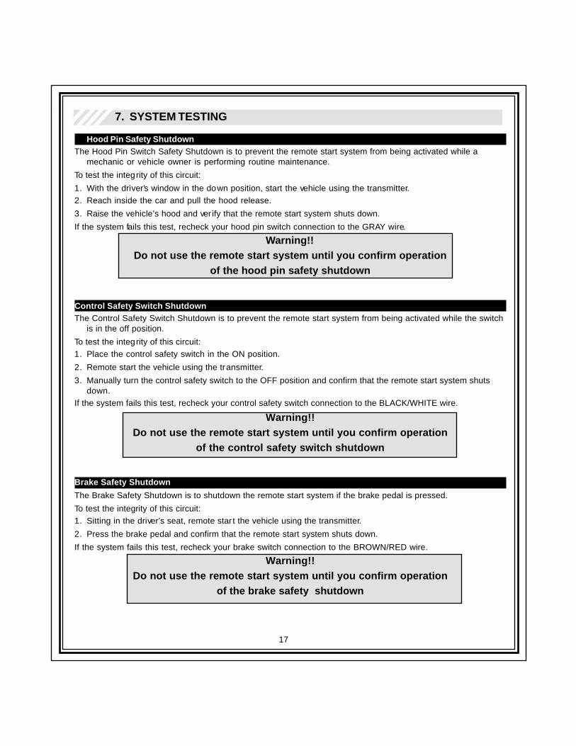
Hood Pin Safety ShutdownThe Hood Pin Switch Safety Shutdown is to prevent the remote start system from being activated while a
mechanic or vehicle owner is performing routine maintenance.
To test the integrity of this circuit:
1. With the driver’s window in the down position, start the vehicle using the transmitter.2. Reach inside the car and pull the hood release.
3. Raise the vehicle’s hood and ver ify that the remote start system shuts down.
If the system fails this test, recheck your hood pin switch connection to the GRAY wire.
Warning!!Do not use the remote start system until you confirm operation
of the hood pin safety shutdown
Control Safety Switch ShutdownThe Control Safety Switch Shutdown is to prevent the remote start system from being activated while the switch
is in the off position.
To test the integrity of this circuit:1. Place the control safety switch in the ON position.
2. Remote start the vehicle using the transmitter.
3. Manually turn the control safety switch to the OFF position and confirm that the remote start system shutsdown.
If the system fails this test, recheck your control safety switch connection to the BLACK/WHITE wire.
Warning!!Do not use the remote start system until you confirm operation
of the control safety switch shutdown
Brake Safety Shutdown
The Brake Safety Shutdown is to shutdown the remote start system if the brake pedal is pressed.
To test the integrity of this circuit:1. Sitting in the driver’s seat, remote star t the vehicle using the transmitter.
2. Press the brake pedal and confirm that the remote start system shuts down.
If the system fails this test, recheck your brake switch connection to the BROWN/RED wire.
Warning!!Do not use the remote start system until you confirm operation
of the brake safety shutdown

18
NOTES: