Embed Size (px)
Citation preview

“Assessment of Applications of Force Sensing Materials in Robotics”
ET-493_01Senior Design I
Cris Koutsougeras / Junkun MaAdvisor: Mohammad Saadeh
Spring 2016
Andrew AllemondW0511221
Mechanical Engineering TechnologyBlake Dufour
W0442892Mechanical Engineering Technology
ET-493_01 Andrew AllemondSenior Design I W0511221Spring 2016 Blake DufourCris Koutsougeras / Junkun Ma W0442892
Table Of ContentsAbstract…………………………………………………………………………………………....3
Introduction………………………………………………………………………………………..4
Background………………………………………………………………………………………..5
Piezoelectricity………………………………………………………………………………….6-7
Piezoelectric FDT Sensor ……………………………………………………………………....8-9
Sensor Sampling Materials…………………………………………………………………...10-13
Timeline………………………………………………………………………………………….14
References………………………………………………………………………………....……..15
Southeastern Louisiana University500 Western Ave. Hammond, LA 70402
College of Computer Science and Industrial Technology Department of Engineering Technology
ET-493_01 Andrew AllemondSenior Design I W0511221Spring 2016 Blake DufourCris Koutsougeras / Junkun Ma W0442892
Abstract:
Create a tactile sensor system into two realistic-looking artificial skin gloves. These
artificial skin tactile sensors will use suitable technologies (Research is needed in order to
determine the best suitable technology needed) to measure applied force at multiple points on
each glove. The sensors will have to be placed in certain areas of the glove in order to receive a
full reading of the force on the entire hand. The use of an Open Source Program will be needed
in this step (Arduino or Raspberry Pi). The gloves will be created using silicone rubber to
simulate both the texture and look of human skin, while maintaining both flexibility and
durability (research will be needed in order to determine a suitable silicone rubber product with
molding capabilities). Sensor data will first be sent via USB to a computer, where a graphical
user display will be created to show the tactile information in real time. The use of an Open
Source Program will be used in this step (Research still needed on a suitable program for this
step). Once the gloves are completed, research will be needed in order to wirelessly record the
data (XBee’s or Raspberry Pi’s equivalent wireless communication).
Southeastern Louisiana University500 Western Ave. Hammond, LA 70402
College of Computer Science and Industrial Technology Department of Engineering Technology
ET-493_01 Andrew AllemondSenior Design I W0511221Spring 2016 Blake DufourCris Koutsougeras / Junkun Ma W0442892
Introduction:
With technology making ever more advanced mechanical manipulators possible. The
field of robotics now has a need for tactile sensors that are more advanced than those already in
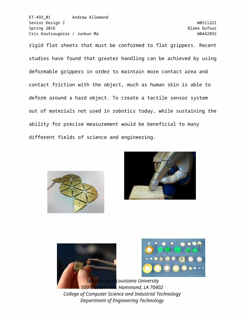
society. Current tactile sensors consist mainly of rigid or semi-rigid flat sheets that must be
conformed to flat grippers. Recent studies have found that greater handling can be achieved by
using deformable grippers in order to maintain more contact area and contact friction with the
object, much as human skin is able to deform around a hard object. To create a tactile sensor
system out of materials not used in robotics today, while sustaining the ability for precise
measurement would be beneficial to many different fields of science and engineering.
Southeastern Louisiana University500 Western Ave. Hammond, LA 70402
College of Computer Science and Industrial Technology Department of Engineering Technology
ET-493_01 Andrew AllemondSenior Design I W0511221Spring 2016 Blake DufourCris Koutsougeras / Junkun Ma W0442892
Background:
Often times sensors are used to quantify information about the environment, such as telling
temperature or force. Sensors are sometimes used to relay information from an inaccessible location, such
as beyond a wall or inside a chamber. Many times they provide information beyond the capability of
human senses, such as extremely high speeds. In other cases, the sensor can provide a range of data about
the measurement, such as the magnitude of a force value relative to a known measurement. Perhaps the
most basic sense, but also the most useful type of sensor is one that provides input about pressure or
force. Sensing the magnitude of the force via touch is crucial when dealing with fragile objects, such as
picking up an egg or screwing in a light bulb. If too great a force is exerted on a fragile object, the object
is likely to break. Today’s society has relied on resistive force sensing modules in robotics, which has
limited the advancements of sensing. The use of a new sensing ability will bring light to the advancement
in this field of study.
Southeastern Louisiana University500 Western Ave. Hammond, LA 70402
College of Computer Science and Industrial Technology Department of Engineering Technology
ET-493_01 Andrew AllemondSenior Design I W0511221Spring 2016 Blake DufourCris Koutsougeras / Junkun Ma W0442892
Piezoelectricity:
Piezoelectricity was first discovered by Pierre and Jacques Curie in 1880 when they found
electric surface charges appearing on specially prepared crystals (tourmaline, quartz, topaz, cane sugar,
and Rochelle salt among them) when subjected to a mechanical stress. Scientifically, the relationship
between applied forces and the resultant responses in piezoelectric materials is caused by the atomic
lattice structures of the material. In piezoelectric materials, this lattice structure has an essential unit or
“cell” of a cubic or rhomboid cage made of atoms. Inside this cell is a single semi-mobile ion which has
several stable quantum states. This post-ion state of the ion can be caused to shift by either deforming the
cage through applied strain or by applying an electric field.
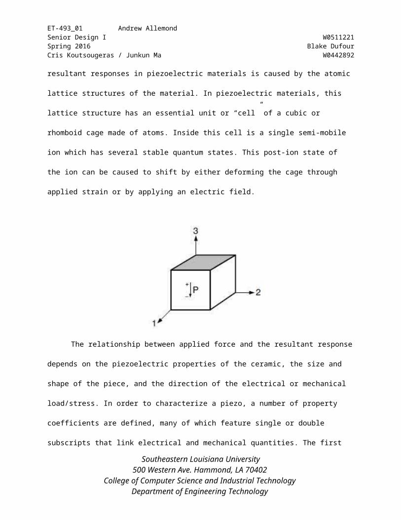
The relationship between applied force and the resultant response depends on the piezoelectric
properties of the ceramic, the size and shape of the piece, and the direction of the electrical or mechanical
load/stress. In order to characterize a piezo, a number of property coefficients are defined, many of which
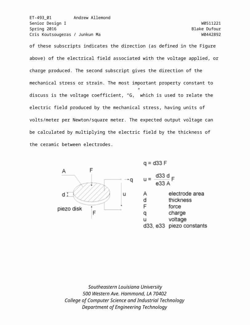
feature single or double subscripts that link electrical and mechanical quantities. The first of these
subscripts indicates the direction (as defined in the Figure above) of the electrical field associated with the
voltage applied, or charge produced. The second subscript gives the direction of the mechanical stress or
strain. The most important property constant to discuss is the voltage coefficient, “G,” which is used to
Southeastern Louisiana University500 Western Ave. Hammond, LA 70402
College of Computer Science and Industrial Technology Department of Engineering Technology
ET-493_01 Andrew AllemondSenior Design I W0511221Spring 2016 Blake DufourCris Koutsougeras / Junkun Ma W0442892
relate the electric field produced by the mechanical stress, having units of volts/meter per Newton/square
meter. The expected output voltage can be calculated by multiplying the electric field by the thickness of
the ceramic between electrodes.
Piezoelectric FDT Sensor:
Southeastern Louisiana University500 Western Ave. Hammond, LA 70402
College of Computer Science and Industrial Technology Department of Engineering Technology
ET-493_01 Andrew AllemondSenior Design I W0511221Spring 2016 Blake DufourCris Koutsougeras / Junkun Ma W0442892
The “F” in FDT Series stands for “‘Flexible Leads”. These are rectangle elements of Piezo film with silver
ink screen printed electrodes. Rather than making the lead attachment near the sensor, the Piezo polymer tail extends
from the active sensor area as flex circuit material with offset traces. This gives a very flat, flexible lead with a
connector at the end. The FDT elements are available in a variety of different sizes and thicknesses. They are
available without a laminate (FDT), with a laminated (0.005” mylar) on one side (FLDT) or with tape release layer
adhesive (FDT with adh) in the sensor area.
The connector pins on the FDT sensors can be directly soldered to a PCB with a reasonable level of care.
This component cannot withstand high temperatures (>80°C) and therefore soldering of the pins to a PCB must be
done quickly. A heat sink clamped to the interface area between the film and the crimps will take the heat away
from the film. Pre-tin the pins and then quickly solder them to the board. Do not allow the soldering iron to touch
the film and do not use a dwell time of more than 5 seconds on the pins. Low temperature solder can also be
used.
The idea of using piezoelectricity as a force sensor is to use the electrical charge generated when
polyvinylidene fluoride (PVDF) film is deformed on impact, i.e. pressed, bent, etc. The measured voltage is
proportional to the applied force in an area of the film. These come in different sizes and thicknesses to fit the
application at hand. The physical dimensions and properties of the films available to us are listed in reference to
each individual sensor. Piezoelectric materials are anisotropic, meaning that the response to pressure will be
dependent on the axis on which the pressure is applied. As we will be applying pressure on the thickness of the film,
i.e. the third axis the voltage will be directly proportional to the force applied.
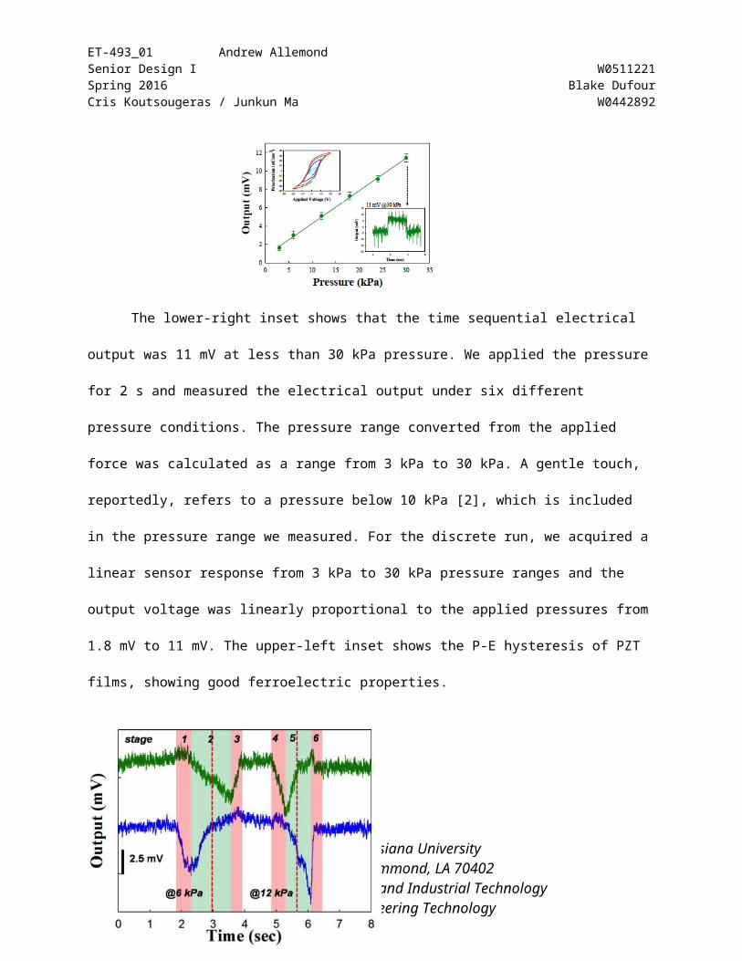
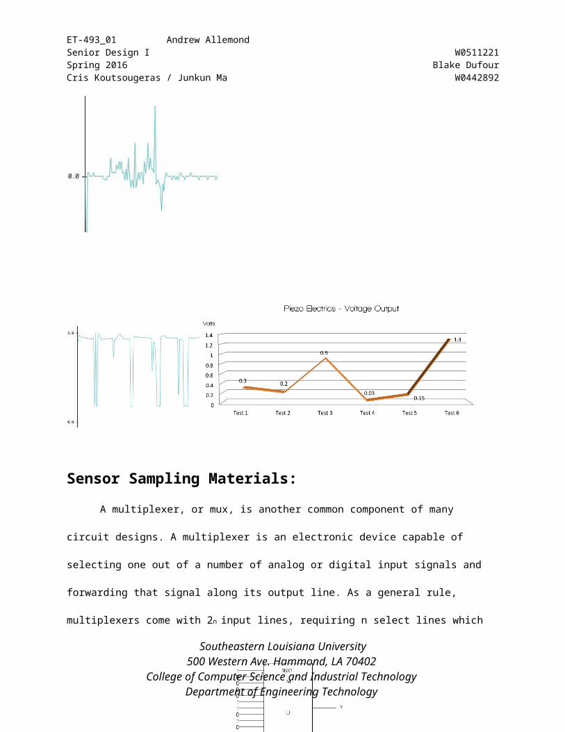
The lower-right inset shows that the time
sequential electrical output was 11 mV at less than 30 kPa pressure. We applied the pressure for 2 s and Southeastern Louisiana University
500 Western Ave. Hammond, LA 70402 College of Computer Science and Industrial Technology
Department of Engineering Technology
ET-493_01 Andrew AllemondSenior Design I W0511221Spring 2016 Blake DufourCris Koutsougeras / Junkun Ma W0442892
measured the electrical output under six different pressure conditions. The pressure range converted from
the applied force was calculated as a range from 3 kPa to 30 kPa. A gentle touch, reportedly, refers to a
pressure below 10 kPa [2], which is included in the pressure range we measured. For the discrete run, we
acquired a linear sensor response from 3 kPa to 30 kPa pressure ranges and the output voltage was
linearly proportional to the applied pressures from 1.8 mV to 11 mV. The upper-left inset shows the P-E
hysteresis of PZT films, showing good ferroelectric properties.
Sensor Sampling Materials:
Southeastern Louisiana University500 Western Ave. Hammond, LA 70402
College of Computer Science and Industrial Technology Department of Engineering Technology
ET-493_01 Andrew AllemondSenior Design I W0511221Spring 2016 Blake DufourCris Koutsougeras / Junkun Ma W0442892
A multiplexer, or mux, is another common component of many circuit designs. A multiplexer is
an electronic device capable of selecting one out of a number of analog or digital input signals and
forwarding that signal along its output line. As a general rule, multiplexers come with 2n input lines,
requiring n select lines which are used to choose which input line to forward to the output. A multiplexer
thus makes it possible to send several signals worth of data over a single communication line, rather than
having one line per device. A multiplexer will be used in this project in order to read multiple
Piezoelectric sensors simultaneously throughout the many different data analysis components of the
project.
Operational amplifiers are high-gain electronic amplifiers feature a differential input and usually
a single-ended output, capable of amplifying some voltage hundreds to thousands of times larger than the
voltage difference between the inputs. Ideally, an op-amp has an input offset voltage of zero, as well as
infinite input resistance. While ideal op-amps do not exist in real life, present day op-amps have come so
close to ideal that they can usually be assumed as ideal for analysis purposes. A multitude of circuits can
be created using op-amps, including noninverting amplifiers, inverting amplifiers, differential amplifiers,
adding circuits, and many others, each serving a different purpose. When operating at unity gain (no
amplification), the noninverting amplifier reduces to a voltage follower, where the output voltage is
identical to the input voltage. By using an op-amp to create a voltage follower circuit, a high impedance
input source can be buffered to a low impedance output. When used with a piezoelectric sensor, it allows
for measuring of the voltage difference, while greatly reducing charge leakage.
Southeastern Louisiana University500 Western Ave. Hammond, LA 70402
College of Computer Science and Industrial Technology Department of Engineering Technology
ET-493_01 Andrew AllemondSenior Design I W0511221Spring 2016 Blake DufourCris Koutsougeras / Junkun Ma W0442892
Invented in 1833 by Samuel Hunter Christie and later improved upon by Charles Wheatstone in
1843, the Wheatstone bridge is an electrical circuit used to measure an unknown electrical resistance by
balancing two legs of a bridge circuit where one leg includes the unknown component. The main benefit
of the Wheatstone bridge is that it can provide extremely accurate measurements unlike a simple voltage
divider. A Wheatstone bridge’s ability to measure is similar to an original potentiometer; however, its
initial purpose was for soils analysis and comparison.
An example of the Wheatstone bridge is featured in the example above. Rx symbolizes the
unknown resistance to be measured with R1, R2, and R3 are the resistors with a known value of
resistance and R2 is the resistance that is adjustable. The theory states that if the ratio of the two
resistances in the known leg (R2, R1) is equal to the ratio of the two in the unknown leg (Rx,R3), then the
voltage between the two midpoints (Band D) will be zero and no current will flow through the
galvanometer Vg. Therefore, when the bridge is unbalanced, the direction of the current indicates whether
Southeastern Louisiana University500 Western Ave. Hammond, LA 70402
College of Computer Science and Industrial Technology Department of Engineering Technology
ET-493_01 Andrew AllemondSenior Design I W0511221Spring 2016 Blake DufourCris Koutsougeras / Junkun Ma W0442892
R2 is too low or too high. Since R2 is variable, the galvanometer reads zero once there is no current
passing through. A galvanometer is highly accurate. Thus, if R1, R2, and R3 are known to be highly
accurate, then Rx can be found to the same level of accuracy. Any small changes in Rx are easily and
quickly detected.
At the point where balance is achieved, the ratio of R2/R1=Rx/R3 or it can be done as Rx=R2/R1
x R3. In other words, if R1, R2, R3 are known and R2 is not adjustable, the difference of voltage across
or current flow through the meter can be used to calculate the value of Rx, using Kirchhoff’s circuit laws.
This is used frequently in resistance thermometer and strain gauge measures, since it is faster to read a
voltage level off a meter than to adjust a resistance to zero voltage.
What all of this means is that the Wheatstone bridge demonstrates the concept of a difference
measurement, which can be extremely accurate. Variances on the Wheatstone bridge can be used to
measure capacitance, inductance, impedance and other quantities. The Wheatstone bridge was specially
adapted and the Kelvin bridge was developed from the Wheatstone bridge to measure very low resistance.
This is important because measuring the unknown resistance is related to measuring the impact of a
certain physical event such as temperature, pressure, or force and this allows the use of the Wheatstone
bridge in measuring these elements indirectly. Later developments upon the Wheatstone bridge was
conducted to measure alternating current measurements by James Clark Maxwell in 1865 and again by
Alan Blumlein in 1926.
Processing is an open source programming language and environment meant to create images,
animations, and interactions. Because the Arduino programming environment is based on the Processing
programming environment, Processing was chosen to create a graphical user display. This graphical user
display would enable viewing the data from each sensor in real-time using a computer screen. Several
sample programs included in the Arduino programming environment provided instruction for how to read
Southeastern Louisiana University500 Western Ave. Hammond, LA 70402
College of Computer Science and Industrial Technology Department of Engineering Technology
ET-493_01 Andrew AllemondSenior Design I W0511221Spring 2016 Blake DufourCris Koutsougeras / Junkun Ma W0442892
data from the serial port using Processing, and a multitude of tutorials on the Processing website provided
instruction for drawing simple shapes for a graphical display.
Timeline:
February 10th – 24th:
Southeastern Louisiana University500 Western Ave. Hammond, LA 70402
College of Computer Science and Industrial Technology Department of Engineering Technology
ET-493_01 Andrew AllemondSenior Design I W0511221Spring 2016 Blake DufourCris Koutsougeras / Junkun Ma W0442892
Research piezoelectric sensors. Research method for sampling multiple sensors. Research data acquisition method.
March 3rd – 16th:
Order Materials for testing purposes. Research piezoelectric equations.
March 16th – 23rd:
Code microcontroller for sampling sensors. Receiving materials.
March 23rd – April 6th:
Sample sensors for quality assurance. Perform data analysis of sensors. Create graphical display of sensor data analysis.
April 6th – 20th:
Infiltrate sensors into silicone medium. * Perform data analysis of sensors in silicone medium. * Create graphical display of data analysis. *
April 20th – May 4th:
Research live-feed software for graphical display. Code software for live-feed display. Prepare/critique end of semester final presentation.
(* Items are Subject to change)
References:
Analog/Digital MUX Breakout. (2010). Retrieved February 16, 2016, from SparkFun Electronics:
Southeastern Louisiana University500 Western Ave. Hammond, LA 70402
College of Computer Science and Industrial Technology Department of Engineering Technology

ET-493_01 Andrew AllemondSenior Design I W0511221Spring 2016 Blake DufourCris Koutsougeras / Junkun Ma W0442892
http:// www.sparkfun.com/commerce/product_info.php?products_id=9056
FingerTipMulti-Touch Screen Controller with Ultra-Low Power. (n.d.). Retrieved March 02, 2016, from
http://www.st.com/web/catalog/sense_power/FM89/SC1717/SS990/PF251157
Operational Amplifier Basics - Op-amp tutorial. (2013). Retrieved February 27, 2016, from
http://www.electronics-tutorials.ws/opamp/opamp_1.html
Mancini, R. (2002, August). Op Amps For Everyone. Retrieved January 20, 2016, from Texas
Instruments: http:// focus.ti.com/lit/an/slod006b/slod006b.pdf
Piezo Systems, I. (2008). Introduction of Piezo Transducers. Retrieved January 9, 2016, from Piezo.com:
http:// www.piezo.com/catalog7C.pdf%20files/Cat7C.20,21,22,23,60,61&62.pdf
Stutz, M. (2001). Multiplexers. Retrieved February 16, 2016, from
http ://www.allaboutcircuits.com/textbook/digital/chpt-9/multiplexers /
Southeastern Louisiana University500 Western Ave. Hammond, LA 70402
College of Computer Science and Industrial Technology Department of Engineering Technology