Embed Size (px)
Citation preview
WWW.TUNINGTECHFS.COM 1654 CROFTON BLVD., STE 8, CROFTON, MD 21114
WWW.TUNINGTECHFS.COM
CSL Map Sensor Modification Instructions for E46 M3 Coupe,
Convertible 2001 -2006
Sources for map sensor:
1) Frank Smith, included with the DME modifications and sent as part of the kit
2) Source the parts as indicated below: Rock Auto and other online vendors will sell the
Part number cross references to: 12569240, 16137039, 16254719 and 213356 to assist with searching.
Wiring for the map sensor requires both a harness for the map sensor with associated wiring, along with
a pin and wire to connect to the ECU follows:
E46 M3 DME Overview
– Modifications will relate to “Performance Controls” are of the DME

WWW.TUNINGTECHFS.COM 1654 CROFTON BLVD., STE 8, CROFTON, MD 21114
WWW.TUNINGTECHFS.COM
Plug x60003 on the BMW DME side
Preparation Step 1 – Remove Power
Disconnect the battery ground connector (BLACK) at the battery – (Rear truck)
Step 2 – Remove DME Cover
Remove DME compartment cover
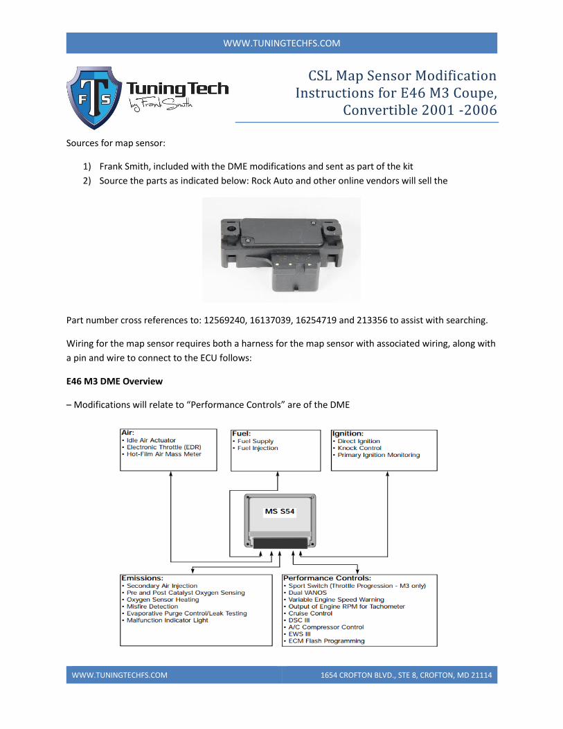
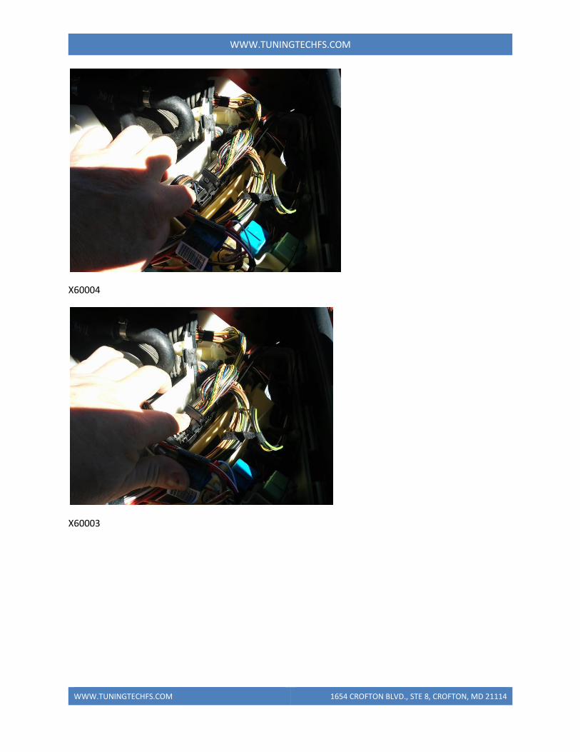
Step 3 – Remove DME Connectors
Remove DME connections in the following order depressing lock clips as needed:
X60005
WWW.TUNINGTECHFS.COM 1654 CROFTON BLVD., STE 8, CROFTON, MD 21114
WWW.TUNINGTECHFS.COM
X60004
X60003
WWW.TUNINGTECHFS.COM 1654 CROFTON BLVD., STE 8, CROFTON, MD 21114
WWW.TUNINGTECHFS.COM
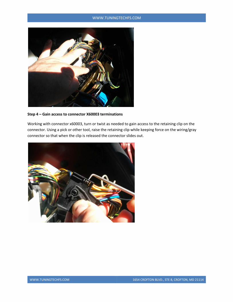
Step 4 – Gain access to connector X60003 terminations
Working with connector x60003, turn or twist as needed to gain access to the retaining clip on the
connector. Using a pick or other tool, raise the retaining clip while keeping force on the wiring/gray
connector so that when the clip is released the connector slides out.
WWW.TUNINGTECHFS.COM 1654 CROFTON BLVD., STE 8, CROFTON, MD 21114
WWW.TUNINGTECHFS.COM
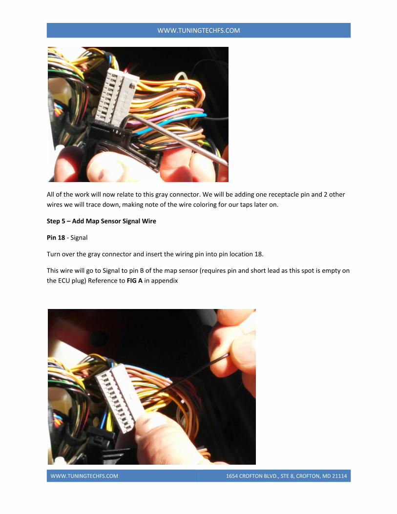
All of the work will now relate to this gray connector. We will be adding one receptacle pin and 2 other
wires we will trace down, making note of the wire coloring for our taps later on.
Step 5 – Add Map Sensor Signal Wire
Pin 18 - Signal
Turn over the gray connector and insert the wiring pin into pin location 18.
This wire will go to Signal to pin B of the map sensor (requires pin and short lead as this spot is empty on
the ECU plug) Reference to FIG A in appendix
WWW.TUNINGTECHFS.COM 1654 CROFTON BLVD., STE 8, CROFTON, MD 21114
WWW.TUNINGTECHFS.COM
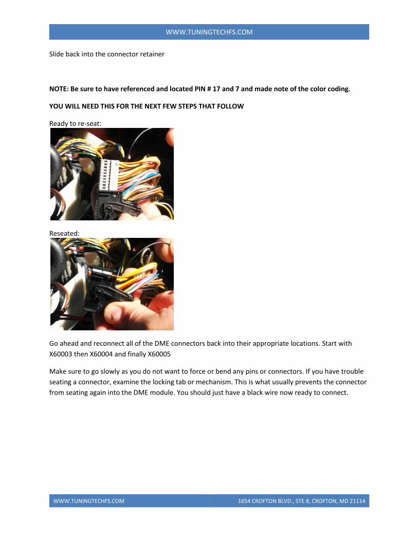
Slide back into the connector retainer
NOTE: Be sure to have referenced and located PIN # 17 and 7 and made note of the color coding.
YOU WILL NEED THIS FOR THE NEXT FEW STEPS THAT FOLLOW
Ready to re-seat:
Reseated:
Go ahead and reconnect all of the DME connectors back into their appropriate locations. Start with
X60003 then X60004 and finally X60005
Make sure to go slowly as you do not want to force or bend any pins or connectors. If you have trouble
seating a connector, examine the locking tab or mechanism. This is what usually prevents the connector
from seating again into the DME module. You should just have a black wire now ready to connect.
WWW.TUNINGTECHFS.COM 1654 CROFTON BLVD., STE 8, CROFTON, MD 21114
WWW.TUNINGTECHFS.COM
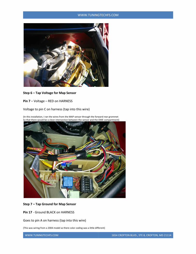
Step 6 – Tap Voltage for Map Sensor
Pin 7 – Voltage – RED on HARNESS
Voltage to pin C on harness (tap into this wire)
(In this installation, I ran the wires from the MAP sensor through the forward rear grommet So that there would be a clean intersection between the sensor and the DME compartment)
Step 7 – Tap Ground for Map Sensor
Pin 17 - Ground BLACK on HARNESS
Goes to pin A on harness (tap into this wire)
(This was wiring from a 2004 model so there color coding was a little different)
WWW.TUNINGTECHFS.COM 1654 CROFTON BLVD., STE 8, CROFTON, MD 21114
WWW.TUNINGTECHFS.COM
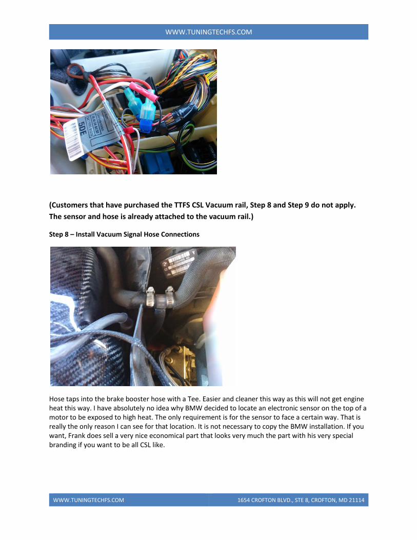
(Customers that have purchased the TTFS CSL Vacuum rail, Step 8 and Step 9 do not apply.
The sensor and hose is already attached to the vacuum rail.)
Step 8 – Install Vacuum Signal Hose Connections
Hose taps into the brake booster hose with a Tee. Easier and cleaner this way as this will not get engine heat this way. I have absolutely no idea why BMW decided to locate an electronic sensor on the top of a motor to be exposed to high heat. The only requirement is for the sensor to face a certain way. That is really the only reason I can see for that location. It is not necessary to copy the BMW installation. If you want, Frank does sell a very nice economical part that looks very much the part with his very special branding if you want to be all CSL like.
WWW.TUNINGTECHFS.COM 1654 CROFTON BLVD., STE 8, CROFTON, MD 21114
WWW.TUNINGTECHFS.COM
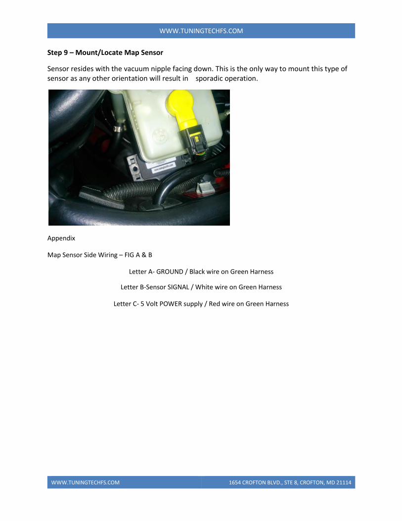
Step 9 – Mount/Locate Map Sensor
Sensor resides with the vacuum nipple facing down. This is the only way to mount this type of sensor as any other orientation will result in sporadic operation.
Appendix
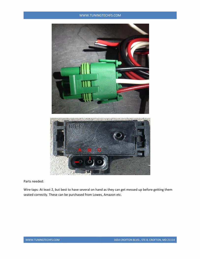
Map Sensor Side Wiring – FIG A & B
Letter A- GROUND / Black wire on Green Harness
Letter B-Sensor SIGNAL / White wire on Green Harness
Letter C- 5 Volt POWER supply / Red wire on Green Harness
WWW.TUNINGTECHFS.COM 1654 CROFTON BLVD., STE 8, CROFTON, MD 21114
WWW.TUNINGTECHFS.COM
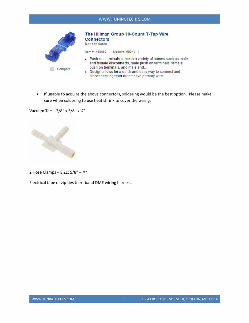
Parts needed:
Wire taps: At least 2, but best to have several on hand as they can get messed up before getting them
seated correctly. These can be purchased from Lowes, Amazon etc.
WWW.TUNINGTECHFS.COM 1654 CROFTON BLVD., STE 8, CROFTON, MD 21114
WWW.TUNINGTECHFS.COM
If unable to acquire the above connectors, soldering would be the best option. Please make
sure when soldering to use heat shrink to cover the wiring.
Vacuum Tee – 3/8” x 3/8” x ¼”
2 Hose Clamps – SIZE: 5/8” – ¾”
Electrical tape or zip ties to re-band DME wiring harness.